SolidWorks A Brief Description
|
|
|
- Philippa McBride
- 9 years ago
- Views:
Transcription
1 SolidWorks A Brief Description 2:1

2 SolidWorks The purpose of the laboratory in ME152 is to be able to apply topics learned in the lecture section of the course as well as ME151 in a CAD environment. The purpose of ME153 is to expand on the skills learned in ME152. This course goal is not to teach the program, but to present enough of it so that the student can present well documented engineering drawings which utilize proper views and dimensions. The CAD platform, SolidWorks, is the program which will be utilized to this end. Warning: Do not use shortcuts! Whenever learning a new platform strict adherence to proper protocols and procedures is essential for establishing a firm foundation of good habits. This also eases a transition to any other CAD platform. Types of files: In SolidWorks there are several types of files used. The most common is the Part File which has an extension SLDPRT. (SolidWorks automatically appends the extension so you do not have to worry about it.) This type of file is where all the components are constructed. Each part must be one contiguous piece and there may be only one component in each part file. In advanced workings, there may be several different configurations of a part in a file, but it is still essentially one part in the file. An Assembly File (extension SLDASM) is where parts or sub-assemblies are joined together to create a machine. The assembly may be static or dynamic. In the dynamic assembly the parts are allowed to move as they would in the actual assembled part. The assembly may be exploded to show how all the parts go together. Section views of the assembly are also possible. A bill of materials (parts lists) is included in the assembly file. The Drawing File (extension SLDDRW) is where the actual engineering drawings are produced. Multiple views of a part, section views, detail views and auxiliary views are all included. Coordinate dimensions and geometric dimension tolerancing are included in the proper views. The drawing will have a title block where all pertinent information about the part in the drawing is listed. There will be special title blocks for ME152 and ME153 which will be available to the student. Assemblies are also put into drawings. All the files are related. Once a part is placed into an assembly or a drawing, the file name may not be changed arbitrarily. Get in the habit of giving the files the proper names when they are created. All of your files will be named yourlastnamexx where the XX represents the particular lab, i.e. ludin5a. If multiple parts are needed label them ludin5a1, ludin5a2 etc. A part, assembly and drawing may have the same name as they have different extensions applied to them. A drawing may not be opened if the part file from which it was created cannot be located. This often happens if a file name is changed. When you submit an electronic copy of a drawing, be sure all supporting part and assembly files are included as well. If a part is changed (made longer or thicker for example), then the drawing or assembly which contains that part will also be changed. 2:2

3 Template files are used to save set up time. The most common template will be the drawing sheet format which will contain the title block for the course. These templates are regular drawing files and have the extension SLDDRW. The course templates will have names such as TBLAND.slddrw or TBPOR.slddrw, as both portrait and landscape views will be used. These may be found on the server in To get to the server follow the steps: Start : My Computer : My Network Places : Entire Network : Microsoft Windows Network : pclab : MELAB02 : ME152 or ME153. All files needed for the course will be here. On all the department computers there is a hard drive section called Thawspace. This is a working file for student use. Create a new folder with your name on it and place your work in the folder. Save all your work here as you develop your parts and drawings. When you are done drag the files to your flash drive or other storage medium for permanent storage. Save your work often (ctrl-s) as you develop a part. Saving to the hard drive takes almost no time. When your system crashes which happens often enough to be concerned, your work will be recoverable. Before leaving the lab delete the folder you created. Thawspace size is limited. File management is critical with SolidWorks. Most assignments in the course require multiple files. Make sure that they are kept together in one place since if a file is misplaced, all the files that depend on that one will not open. In the simplest cases there might be a part file and drawing file. Later there may be several part files, an assembly file, and a drawing file. One missing file can prevent the use of the others. If a file is going to be used in another drawing use Save As and then Save as a Copy to create another file. Creating a Part and Drawing When SolidWorks is first opened, you have to open a part, assembly or drawing. When a new part is opened, there is a blank work area on the right and a column on the left called the Feature Manager. In the Feature Manager, there are the three main planes listed front, top and right. To begin a sketch, a plane to draw on must be selected. Right click on the desired plane and select the sketch icon in the fly-out menu. For the first sketch the view will rotate so that you are looking perpendicular to the plane you selected. The first feature sketched is called the base feature. Added on features are called boss or cut features. These add or subtract material to create the part. It is best to keep the geometry of each feature as simple as possible. Create a part with a large number of simple features rather than a few complex ones. Your work will be much easier to perform and less prone to errors in the long run. Plan how the part is going to be used before beginning the sketch. Which faces do you want for the front, top and right views? Where do you want the origin to be? It is easier to take a few minutes and plan ahead than to have to redo a part because the wrong orientation was used. A quick hand sketch on a sheet of paper to determine the final appearance can save a lot of effort and time. A good habit to get into is to place the origin on a plane of symmetry if there is one. This will save you a lot of work in creating a part. 2:3

4 When you start sketching the base, rough out what the base face will look like. It does not have to be exactly to dimensions. When you finish your rough sketch most lines will be blue. This means that you have an under-defined sketch. At this point you add geometric relations or constraints and dimensions to the drawing to get it completely defined. A fully defined sketch has all black lines. You will also see near the bottom right of the screen a note Fully Defined. If it says u\ Under Defined you will need more dimensions or relations before extruding. If you try to define it too much the sketch turns red meaning that it is over-defined. At this point you will have to remove some relations or dimensions to get back to completely defined. Once you have a fully defined sketch, then you can extrude it or revolve it to create the base. Get in the habit of extruding and cutting with fully defined features only as it will save time and effort later on. After the base feature is created, additional features may be added. Again the new features must be sketched on a plane. This plane can be one of the three primary planes, one of the faces of the base or any boss, or on a user defined plane. Right click on the plane desired, then select the sketch icon. In the transparent view menu o at the top of the work area select the view orientation to do the sketch. Try to use the geometric relations as much as possible to orient a new feature to a previous feature. Thus if the first feature is changed, the second feature will follow along with it rather than having to be redimensioned. SolidWorks is a parametric program, which means that the dimensions drive the size and shape of the part rather than the reverse. The benefit of this is that a part s size and shape can be altered by just changing the appropriate dimension rather than having to redraw the part. Careful selection of the geometric relations and dimensions can simplify the task. A drawing is where the various views of a part are made. You may select which views to include. The standard three view also called the third angle view, inserts the front, top and right view. Named views, such as left, bottom, back, isometric, etc., may be added. Section views and auxiliary views may be created from any view present. Each view may be dimensioned. SolidWorks will automatically dimension the drawing. However it does not do a perfect job. It is up to the user to place the dimensions in the proper places and on the proper view. If a dimension is not needed use the hide feature to eliminate it rather than deleting it. That way the dimension may be recalled if necessary. On all drawings the title block should be present and filled out. It should contain at least your name, lecture section number, lab section number, date, drawing name and drawing number. In detail drawings include also the scale and units. These are not necessary in assembly drawings, but are preferred. If requested also add the material, next assembly and tolerance default to the part drawing. It is the drawing that will be printed up and turned in as a hard copy. When an assembly is put into a drawing, balloons should be added to each part. They will be numbered according to the order the parts were added to the assembly so be careful in the insertion ordering when assembling the parts. A bill of materials will then be added to the drawing. This should include at least the balloon number, part number, part name and quantity. As with parts, the drawing should have Course Title Block as well. 2:4

5 Some Particulars about Parts, Drawings, Printing and Saving As all the computers are used by many people, they will eventually have changed defaults. When opening a new part, assembly or drawing, the first thing to do is to check the units. They should be ANSI and inches or millimeters, depending on the unit system. Go to the menu bar on top, open Tools and click on Options at the bottom of the list. Click on the Document Properties Tab. Under Detailing select ANSI in the pull down menu. Some computers will be already set to ANSI, some to ISO. Make it ANSI. Then pick Units in the white selection tree on the left, and set the units to inches or millimeters in that pull down menu. This should be done whenever a new document is opened. Even if you import a part created with metric units, you will still have to select metric units in the drawing; otherwise the dimensions will be in inches the default. The latest version of SolidWorks has all the commands in the Command Manager near the top of the screen. These are grouped into sketch, assembly, feature and drawing tool bars, each selectable from a tab at the bottom of the command manager. Only the tabs for useable tool bars are shown. The tab for the drawing tools will not be visible when you are creating a part as none of those tools may be used. Likewise the assembly tab will be absent. The sketch and feature tabs will be present as both sets of tools are needed for creating parts. All sketching must be done in a sketch. If you look at the upper right corner of the work area you should see a purple arrow with a pencil and a red X. This is called the sketch confirmation box. This signifies that you are in a sketch. If it is not there you are not in an active sketch and cannot add or change anything. Each feature has its own sketch. (That is why each feature should be given a unique name for identification.) You must be in the correct sketch to change anything in that feature. To reenter a sketch, right click on the desired feature in the feature manager and select Edit Sketch from the selection. To change an extrusion, right click on the feature in the feature manager and select Edit Definition. If you have a part with a plane of symmetry, keep the origin on the plane of symmetry or on the axis of symmetry. You can maintain the symmetry plane as a primary plane by using the Mid- Plane extrusion rather than a blind extrusion. Adding new features will be simplified with this simple step. If you don t do this you will find that you have to define a new plane on the symmetry plane later in the drawing to add features to the part. If a sketch you are working on ever turns red, do not proceed. You have over-defined your feature and should correct the over-definition right then. It could mean that you have included some unwanted relations or have doubled dimensioned a part. Remember that red is bad in SolidWorks. Likewise a yellow line means that you have created an impossible drawing. You may have tried to make two parallel lines collinear or something like that. Again resolve the problem before proceeding. SolidWorks will now warn you when these occur and will make it difficult to proceed without fixing the problem. To see what relations exist in the drawing, make sure nothing is selected and click on the Display/Delete Relations Icon In the Sketch Toolbar. Over-defined relations are marked in red. Look for a relation that you did not put in. That may be the culprit. Try deleting it and see what 2:5

6 happens. Often SolidWorks adds relations it thinks should be there or are implied by your drawing the sketch. Before doing any extrusion, all your feature s lines should be black, indicating that you have a completely defined feature. If a line is blue you still need more dimensions or geometrical relations to fully define your feature. If a feature is going to be created by revolving around a centerline, make all lateral dimensions from the centerline. Before setting the dimension drag it to the other side of the center line and it will become a diameter. Do not use the origin in place of the center line. Use symmetries whenever possible as well. This reduces the drawing time and the amount of dimensioning. If the dimensions of a symmetric feature are changed the symmetric features are also changed. There is a lot of confusion with using center lines and temporary axes. If you are in a sketch creating a feature you use a center line. Center lines are used for sketch mirrors, part alignment and for revolved cuts and extrusions. If you are using feature toolbar tools such as circular pattern, a temporary axis (activated under views temporary axes) is the axis of revolution. Center lines will not work here. Also temporary axes are use in mating circular features in assemblies. Do not create a special sketch just for drawing center lines. If you have to, you are probably doing something wrong. If your cursor turns into what looks like a vacuum cleaner head and you cannot select anything, it means that the selection filter has turned on. Click on the toggle Selection Filter Toolbar which is seen below the Feature Manager and Work Area. Click on the first item to deselect the selection manager. Changing Views. It is best to carefully consider the presentation of what face goes with what view before beginning a part. However if you have selected wrong and discover this well into the part constructions, may be possible to redefine the standard views. Do this change before entering any dimensions in the drawing. With the part showing and all sketches closed, select the view orientation tool on the Feature Tab, or Insert Modify View Orientation, or just press the space bar. The icon looks like a telescope. An orientation dialogue box will appear. Click on the push pin to keep the box open. Double click on the view name in the box which you wish to change. Then single click on the view you wish it to be. Finally, click on the update standard views, the center icon on the top of the box. You will get a warning message which states Changing the standard view will change the orientation of any standard orthogonal, named and child views in the drawings of this model. Select yes to make the change. You may reset the standard views you first selected by clicking on the right icon Reset Standard Views, or by just redefining the standard views again. Click the X in the upper right corner to close the dialogue box when you are done. When setting a scale for a drawing choose a standard setting 1:1, 1:2, 1:4, 1:8, 1:10, 2:1, 4:1 etc. Do not use 1:3 or 2:3 settings. Three is a poor number to work with and should be avoided. 2:6

7 With the views in the drawings you should have hidden lines visible in the standard three views, but hidden lines should not be shown for isometric, section views or auxiliary views. Tangent edges should not be visible except in isometric views with major curved edges that disappear. When this is the case use tangent edges with font or phantom lines. This will give a display with the dashed phantom line for the tangent edges hence distinguishing these edges from part edges. When you are in a drawing, you should always create a special layer for dimensions and another layer for geometrical dimensional tolerances. The layers should be different colors for quick identification of each item. This also allows each particular layer to be turned off if not needed. When dimensions are added to a drawing they will very often become cramped. There are several things you may do to alleviate this cramping. The default length of arrows is.5 inches or 12 mm. If you change these to.2 inches or 5 mm the smaller arrow size will give more room for dimensions. The default font size is about 13 points. A font of 10 to 12 points is appropriate for a size A drawing (8 ½ by 11). Go to Tools Options Document Properties. The Arrow menu will allow you to set the arrow size under length. The Annotations font Dimensions allows the font size to be changed. Do not change the Notes/Balloon font size as that will change the title block size. If a note has to be changed do that in the Property Manager for the particular note under text format. To dimension a hole created by Hole Wizard use the hole callout tool. This tool icon (vn) is found in the annotation tool bar. If the call out gives a THRU or THRU ALL, you will have to delete these notations in the Property Manager. The rest of the callouts for counterbore countersink, depths and angles will be correct. If you are having a callout for a tapped hole, you will also have to delete the pilot hole line. When you are in the edit sheet format entering items into the title block, be very careful when double clicking on an item. If you move the mouse during the clicks you will drag the item out of alignment and need to realign the item. Save your parts and drawings often to the ThawSpace drive on the hard drive. If you experience a crash, you will find the last save you made still on that drive. It is the only nonvolatile section of the computer. When you are done Drag and Drop your files to own drive. You should erase the files on the ThawSpace drive after you are sure that you have good copies. To save your files to a memory device other than ThawSpace, don t use the save as function in the file menu. You should have been saving your file to the hard drive. Go to the desk top and drag the file to the proper drive. You should be using flash memory, which are fairly reliable, but it is always wise to keep a back up copy of your work. In transferring your work to the server again use the drag and drop. Saving to the server locks those files as long as your SolidWorks is open. A major part of your lab grade is from your electronic copy and lost files count against you. You should retain a copy of all your work for the quarter in case there are any questions later on. 2:7

8 If you are in a drawing and have to change the name of a part file, you may use save as on the part file to create the new name. Be sure that both the part, the drawing and possibly the assembly are open before using Save AS. You will get a dialogue box which will allow you to say that you want the line to follow the file. If you just change the name of a part file in Windows, you will break the link and the corresponding drawing file will not be able to open because it will be looking for the old file name. In printing the file, color should not be used. In the printer dialogue box somewhere, depending on the printer and OS, will be a selection to print only in black and white. Select this option before printing. Do not select gray scale as this will result in very light lines. If your printer does not have this feature, then print on the lab computers as light lines will result in grade deductions. Even on a laser printer which prints in black only, select this option and avoid printing in gray scale. The title blocks were designed for the lab s laser printers. Many ink jet printers have different print areas and cut off part of the title block. If this happens you will have to modify the title block or print on the lab computers. Also the SolidWorks watermark may cover up part of the title block information. If this occurs you must add a note (not handwritten) to the drawing listing the covered up information. If parts of the drawing or dimensions are covered by the watermark move the drawing around to clear the information. The printed title blocks must have a complete border around them. Do not change the printer s scale to get the border onto the page as this will result in a drawing with an incorrect altered scale. If you cannot change the title blocks to fit your printer use the lab printers. All the files, title blocks and check points you will need will be placed on the server for Lab You should retrieve the day s files at the beginning of the lab session. To get to the server for ME152 or ME153: Start : My Computer : My Network Places : Entire Network : Microsoft Windows Network : pclab : MELAB02 : ME152 or ME153. Drag files needed over to a folder in the ThawSpace drive to use. If you cannot find pclab in MSNetwork windows, pick Search on the top bar and type in MELAB02. The naming of electronic files is done for my identification of your files. There are hundreds of files turned in each week and they are put into a common folder. The only way your files may be identified is if you use the designated naming procedures. Use only your last name followed by one or two characters a digit and letter for lab identification. If your drawing tools act oddly (big + sign cursors) look to see if there is a command line at the bottom of the screen. To get rid of this got to Tools: Add-ins: and deselect SolidWorks 2D Editor. This editor allows SolidWorks to emulate AutoCAD drawing methods and is something you do not want on. 2:8

9 Student Copies of SolidWorks SolidWorks supplies copies of the current student version of SolidWorks free of charge for students to load into their home computers. The link to the download is available at the ME website: me.calpoly.edu Student Resources - Free and Low Cost Software or me.calpoly.edu/resources/software. This is a 2.1 GB download so a broadband connection is desirous. This version has a 150 day license. After this time SolidWorks will not run and may not be reloaded. The license will also expire on November 30, 2009 even if the 150 days have not expired. This version is nearly the same as the version in lab. However all pages created with the student versions will have a watermark SolidWorks Student License, Academic Use Only. This will appear on every page printed and cannot be removed. It is the student s responsibility to make sure that no vital information is covered up by the watermark. If in information is covered, it must be placed in a note somewhere on the drawing. Also, if printing at home make sure that the printer is set to print in black and white only. Do not print in colors or gray scale. If the borders do not print out as heavy block lines, the printer is in gray scale mode. If that is the case the printers in lab must be used. When SolidWorks is started at home, it will come up with the factory set defaults which are different from those in the lab. The defaults may be set as you wish by going to the menu bar Tools Options. You are encouraged to experiment to get a set of defaults you like. Some of the defaults may be obtained by loading in the templates of the parts and assembly from the lab. To have the same templates on your home computer as are on the lab computer, you may copy the templates in the lab and place them in your hard drive. Open a new part or assembly in the lab. Save it untouched to your own drive. Then on your computer open the file, Save as, and then change the file type to template, and finally save it as a template. It will be placed in the right folder by SolidWorks. The templates contain many of the defaults found in lab. These are the files that are available when you open a new part, assembly or drawing (ctrl n). Student editions of SolidWorks with a two year license may be purchased online from Straight SolidWorks runs about $90 while SolidWorks with COSMOS is about $140. These are still student editions but have all the features found on the lab computers. Note that SolidWorks is a forward compatible software which is updated each year. That means that files created in SolidWorks 2008, for example, may not be opened in SolidWorks 2007, but the reverse is true. SolidWorks 2007 files may be opened in SolidWorks The industrial version is always a year ahead which means that it may not be used for the course as none of the files it creates may be opened in lab. 2:9

10 Geometric Relations: The geometric relations or constraints are a new feature to the first time users of parametric programs. There are several common constraints utilized in fixing features. Note that arcs include full circles. Relation Sketch Entity Changes Undergone Coincident A point and a line or arc Point lies on the arc or line Colinear Two or more lines Lines line on the same theoretical infinite line Concentric Two or more arcs Arcs share the same centerpoint Coradial Two or more arcs Items share the same centerpoint and have equal radii Equal Horizontal or Vertical Two or more lines or two or more arcs One or more lines or two or more points. Line lengths and arc radii stay equal Lines become horizontal or vertical; points are aligned horizontally or vertically. Intersection Two lines and one point Point remains at the intersection of the lines. This can be a projected intersection Midpoint A point and a line Point remains at the midpoint of the line. Parallel Two or more lines Lines become parallel Perpendicular Two lines Lines become perpendicular Pierce Symmetric Tangent A sketch point and an axis, edge, line, arc or spline A centerline and two points. Lines, arcs or splines An arc or spline and a line, arc, or spline Sketch point becomes coincident to where the axis et. al. pierces the plane of the sketch. Items remain symmetrical about the centerline Items remain tangent. 2:10

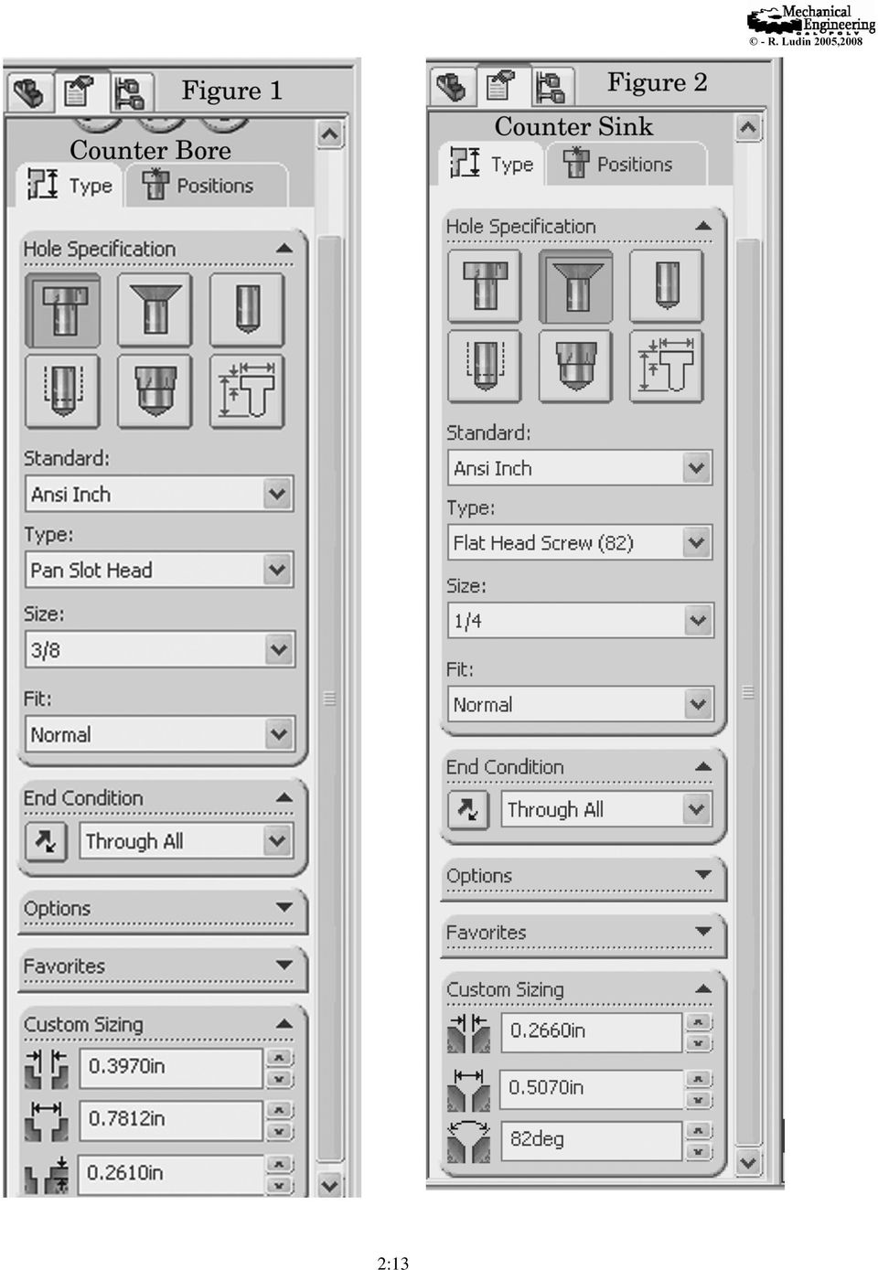
11 Hole Wizard Tool When drilling holes for fasteners using Hole Wizard, first select (left click) where on the part you want the hole placed before opening Hole Wizard. You cannot be in a sketch to use Hole Wizard. Once in the HW menu determine what type of hole you are drilling and pick the proper icon on top counterbore, countersink, hole (regular and clearance) or tapped hole. The standard for all the holes used in this course is ANSI Inch (ANSI metric). If you have more than one hole to add it is best to use Hole Wizard to insert the first hole and then use either a Linear Pattern or Circular Pattern to locate the other holes. To insert a counterbore, first select the proper screw type. (See figure 1 below.) When you make your selection, SolidWorks will then offer a list of available screw sizes for that particular screw. If you cannot find the right size (major diameter) check if you have the correct screw type. The end condition will almost always be through all. To check on the counter bore dimensions open the Custom Sizing Box at the bottom of the Property Manager. You should not change any of the default settings unless absolutely sure that you have to over-ride the defaults. Do not change the defaults as a shortcut. If they are not the correct values, go back and select another screw size. The thru hole will be larger than the major diameter as SolidWorks computes the necessary clearance. To locate the hole select the Positions tab on the top of the manager. Be careful that you do not click any where on the drawing or part as the cursor is by default a point tool and every time you click you add another fixed hole to the part. After picking Positions first select either Add Relations or Smart Dimensions to begin placing the hole. It will usually take a combination of two of these to fully define a hole s position. When it is fully defined click OK twice to add the feature. The same steps are followed for a countersink. (Figure 2.) Select the second icon in the top row. The usual inch screw type is a flat head 82º. A wide head is 100º and a metric is 90º. Placing the hole is done the same way as for a counter bore. When a callout is assigned in the drawings you will have to delete the thru in the callout as thru is now the default. Also any placement location dimensions used in Hole Wizard will have to be added by hand in the drawing. When selecting holes, there are two types to consider, a straight hole and a clearance hole. (Figures 3 and 4.) These are selected under screw type the third icon in the top row. A straight hole is one where you pick the drill size to use on the hole. It is best to select Fractional Drill Sizes for screw type so the size menu will be shorter. For all drill sizes you will have to scroll through all numbered and lettered drill sizes to find the correct size. The sizes are listed from smallest to largest where the numbered and letter drills are usually the smallest. Scroll down to find the size you need. Again check the hole size in the Custom Sizing box. You should not change the dimensions in the Custom Sizing Box. If the dimension is not correct pick the correct drill size in the upper box. The end condition and depth may have to be changed to meet your needs, however. If you need a clearance hole, select Screw Clearance in the pull down menu for screw type. When you pick the size pick the size screw for which you want the clearance hole, SolidWorks will compute the proper clearance size for the screw. For example a clearance hole for a 7/16 inch screw as 2:11
.")
12 shown in Figure 4 will be.4687 inches in diameter for a normal fit (.0312 larger then 7/16 inch). Most holes will be a normal fit. You should only have to change the End Condition and Depth settings. To locate the hole, follow the Positions instructions for the counter bore above. If you need a toleranced hole for a fit such as RC or FN, do not use Hole Wizard. Just do an extruded cut and tolerance the hole in the property manager. If a hole has threads you must use the Tap icon - first icon second row - to get a tapped hole. For type select tapped hole. Only select a bottom tapped hole when the piece you are working with is too thin and a normal tapped hole will have the pilot drill pierce the opposite side. Then find the proper thread size in the pull down menu. Next select the proper end condition. If it is through all you do not have to worry. However if it is a blind hole you will have two conditions. The first is the pilot hole. Do not change this depth. The second condition is the thread depth. This is the value to change if necessary. When this value is changed the pilot hole depth will adjust accordingly. Changing the pilot hole depth manually may result in a situation where the pilot hole is shallower than the thread depth an impossible situation. SolidWorks may then label this feature as a bad feature in the Feature manager. The next box down is the Options box. Check Cosmetic thread and in the pull down menu below, select Without thread callout. Then check thread class the default is 2B. Change this if you have a loose or tight fit. To locate the hole, follow the Positions instructions for the counter bore above. When you use the hole callout icon to dimension a tapped hole in a drawing, there will be a two line callout. The first line is the pilot hole callout. Current practice is to eliminate this line and only have the thread callout. Any good machinist will know which pilot drill to use and the correct depth for a given tapped hole. With a little searching just about any hole for a standard fastener may be found in Hole Wizard, so use the proper hole. Only use Custom Sizing to change the defaults if you know your hole is non-standard. For all of the types of holes after clicking on Positions, do not click in the drawing or anywhere on the part as that will add random holes. First click in the sketch tool bar on Add Relations or Smart Dimensions and then locate the hole to get it fully defined. It usually takes two dimensions and or relations to locate a hole. 2:12

13 2:13
14 2:14

15 Standard Steps for Hole Wizard 1. Click near where the hole is to be located. 2. Select Hole Wizard 3. Select type of hole icon, type of screw, screw size, hole depth and type. 4. Click on Positions Tab; do not click in drawing. 5. Select either Add Relations or Smart dimension and locate the hole. It will usually take two dimensions or relations or one of each to fully define the hole. 6. Select OK twice. 7. To edit either the hole or its position, right click on the name of the part in the Feature Manager and select Edit Feature. 2:15

16 Style Sheet for Drawings There are many different valid ways of presenting drawings. Usually a company will pick one particular set of rules to use for all their drawings. This style sheet is to set out the rules that will be used in this course for drawing presentation, and for various SolidWorks applications. There are always exceptions, but in most cases with a bit of forethought the rules may be followed. Hidden Lines: Hidden lines shall be present in any standard view (front, top, right, back, bottom and left. ) They will not be visible in other views (sections, isometrics, auxiliaries.) GDT: A geometric dimension tolerancing control box should be attached to the edge of a body using a bent leader. Attaching them to extension lines should be avoided. The leaders should not go to a face, but, rather an edge. Only one leader per control box is to be used. If there is more than one control box referencing a given edge, the boxes should be stacked using a single dialog box. The datum box s triangles should also be attached directly to the edge to which they refer. Again extension lines should be avoided if at all possible. The boxes are not to be attached to a control box. Tapped Holes: When callouts for tapped holes are given, the pilot hole dimensions should be deleted. SolidWorks includes them, but current practice is to let the machinist select the proper drill. Thru Holes: Old dimensioning always included THRU or THRU ALL for through holes. Current practice has eliminated these words. In the absence of any depth markings a hole is assumed to be through. When using SolidWorks, be sure to eliminate these words or a specified depth when the hole is through. Scales: For all drawings, both metric and English, use a colon (:) separator in the scale notation rather than an = sign, or a designation like half or full scale. Thus the scale would be given as 1:4, for example. When selecting a scale, do not use any number which is a multiple of 3. Use only 1, 2, 4, 5, 8 and 10. Hole Locations: When a hole is placed using Hole Wizard, the locating dimensions are often not included in the drawing. You will have to put them in manually. Check every hole and see if it is properly dimensioned. It will usually require two dimensions to do this, unless a hole is aligned with another hole or a definite symmetry is clear. Clearance Holes: If a standard fastener is to pass through a hole a clearance hole will be used. This hole is usually.01 to.05 larger than the fastener depending on size. Using a clearance hole feature in Hole Wizard, the clearance will automatically be computed. Tolerances: When adding a default tolerance to a drawing, ±.01 inches or ±0.1 mm are the standards. Selecting too large a tolerance will lead to interference of pieces which have to fit together. Selecting too small a tolerance will drive up the cost of a piece. Whatever 2:16
 They will not be visible in other views (sections, isometrics, auxiliaries.")
17 tolerance you select, the dimensions should have the same number of decimal places as the tolerance. Thus if a ±.01 inch tolerance is used all dimensions should only have two decimal places. If a dimension has to override the default and have more decimals, there should be a tolerance attached to the dimension itself. This occurs often when RC and FN fits are applied. Standard Views: When the standard third angle views are used (Front, Top, Right) they do not have to be labeled, but should be in the proper orientation with each other, i.e. the top view above the front and the right view to the right of the front. In complicated pieces it is often necessary to include a left, back or bottom view to show all the details. These views should be clearly labeled as to what they are even if they are in the proper orientation with the standard views. This applies to the various section views and auxiliary views as well. Tangent Edges: Tangent edges are not to be used in standard drawing views. These are the lines where a flat edge begins to go into a curve. SolidWorks often tries to put these lines in, it is up to you to eliminate them. In an isometric view where there are rounded edges, it is sometimes helpful to include the tangent edges for clarity. If they are included, do not use solid lines, but rather use tangent edges with font. This shows the edges with phantom lines which are clearly discernable fro the regular edges. Concentric Circles: If you have a drawing with several concentric circles, do not dimension then in an end view using leader lines. Put the dimensions in a side view or a lateral section view where the features being dimensioned are clearer. The only concentric circle which should be dimensioned in the end view is the B.C. (bore center) circle which is used to locate the centers of holes. Cutting Lines: When adding a section line in a drawing, make sure that you have the none layer active. Placing a section line in a layer causes the line to turn off when the layer is turned off. The same holds true when adding center lines. The layer of a cutting line or a center line may not be changed once the line has been drawn. Hole Wizard Points: When drilling holes with Hole Wizard, select a point near where the hole is to be located, before entering Hole Wizard. You will have more flexibility locating the hole. If you select the point first, Hole Wizard will create a two dimensional sketch. If the point is not picked first, a three dimensional sketch will be created, causing a more involved feature and possible resulting in a fixed point. When inserting a Bill of Materials (BOM) into an assembly drawing, do not accept the default font; it is too large. Change the font size to 8 points (Tools Options Document Properties - Annotations Font Tables) and manually make the rows and columns as narrow as possible. Attach the BOM to one of the title block corners. When using a lower corner, change the BOM so that the heading is at the bottom and the items read up. 2:17

18 Style Sheet for Parts When creating parts plan ahead before doing any drawing. Decide if there are any planes of symmetry or nearly symmetry. Your origin should be on any plane of symmetry or the intersections of planes of symmetry if there is more than one. Also decide how the part should be oriented what are the front, top and right faces. This will determine the planes to be used for the initial extrusions. A sketch should consist of a closed loops which do not intersect. Each loop should have only one line to follow if you trace it with a pencil. Loops with more than one path, a dangling edge or an open path are called open sketches and should be avoided. These do not extrude properly and can cause problems in the part. Also each sketch should be fully defined before extruding. With the first sketch this will necessitate fixing the sketch to the origin in some way, either through relations or dimensions. If you use dimensions, you will have to make sure that those dimensions are eliminated from the drawing dimensions as they are meaningless for the creation of a part. After extruding, get into the habit of renaming each feature so that it may be quickly identified at a later time for editing. This is documenting your part so that if someone else has to work with your part and possibly modify it, the various features will be easily identifiable. there are free standing sketches you part was not constructed properly. All planes, temporary axes and dimensions should be turned off on a completed part. For the planes and axes, go the view menu in the menu bar and turn each off. Leave the origin on in the part. To hide the dimensions, right click on Annotations in the Feature Manager and select Show Feature Dimensions to turn them off. If any dimensions are still visible, click on them and delete them as they are dimensions that were added when not in the sketch mode and do nothing for the part. When doing a rotational extrude, make sure all diameter dimensions are done utilizing the center line and that there are no radius dimensions in the sketch. When using the fillet tool to round corners or add fillets, do this operation last, so the corners will be available for construction purposes. If two or more fillets or rounds have the same dimensions place them in the same fillet command. When using the shell command, the fillet command has to precede the shell command. When dimensioning angles in features, always use acute angles rather than obtuse angles. That way the acute angle comes into the drawing dimension properly. Also, do not dimension the length of a sloped line, use the angle or two linear dimensions. When your part is completed there should be no free standing sketches sketches that are not part of a feature. If 2:18

19 SolidWorks Terms - Glossary To use this glossary most effectively, read through it each week after lab and check each item covered. Also note the lab demo in which it was used so that you can go back and see an example of the operations involving it. Add Relations Used to connect related geometry. (Concentric, Colinear, Midpoint, Tangent, Parallel, etc. Assembly - An assembly consists of two or more parts mated together. The different parts are called components Auxiliary View Displays a plane parallel to an existing edge on a part with true dimensions. Usually tied to one of the principle views. Axis A straight line used for creating model geometry, features or patterns. Balloons Balloons are numbers in circles used to identify components in an assembly layout. They are connected to the component by a bent leader. Base Feature The first feature created. Serves as the foundation for the part. Usually kept simple. Bill Of Materials A parts list. In an assembly drawing it is a table that relates the components depicted by balloons to the part name, part or drawing number and quantity of the part. Boss Feature Any feature added to a base. Center Marks Two perpendicular intersecting centerlines used to show the center of a hole. Centerline A working line used for mirroring geometries or for setting certain features. Centerlines do not appear in the final model. Chamfer - Removes sharp edges or corners from a feature or part by angling the edge with a flat face. Circular Pattern Creates a circular pattern of a seed diagram in a feature or a sketch. A temporary axis is required to create the pattern. Clearance Hole A nontapped hole for a screw to pass through. The hole is slightly larger thant the screw s major diameter. Collapse The opposite of explode. Returns an exploded assembly view back to its normal state. Component A part or subassembly within an assembly. Conformation Corner: When in a sketch the upper right corner becomes a purple arrow and red X designating that a sketch is open. Construction Line To create a construction line (other than a centerline) in a sketch, draw the entity. In the property manager check the For Construction box and it will change into a construction line which will not be included in the object. 2:19

20 Control-Drag Holding down the control key while dragging an object. Used to copy a feature or a dimension. Control Tab When several windows are open at once use control-tab (hold down the control key and press the tab key) to cycle through them. Keep holding the control key down and you can select the part, assembly or drawing you wish from the selection window which appears. Cosmetic Threads This is the simplified threads representation in SolidWorks. It is found through the menu Insert/Annotations/Cosmetic Threads. Detailed View An enlarged area of an existing view. Used to show fine details in a part. Diameter Dimension When you have a part which is created by a revolution about an axis, do all dimensions across the center line. After rotation they will become diameter dimensions. Dimensions Used to completely define a sketch before extruding or cutting. Dimension Tool Used to enter dimensions into a sketch. Dome Creates a dome on top of a plane end. It may be elliptical, circular, non-elliptical, convex or concave. Drawing One of the three types of files for SolidWorks. This is used to present the working presentations of a part or an assembly. Parts are usually displayed as three view drawings on a title block. Draft Angle The degree of taper applied to a face. Applied to parts which are molded or cast. Drawing Template Contains the title block for each type of layout used. For this course, they will be size A (letter) in either portrait or landscape layouts. Edit Sheet Format Mode In a drawing, this is used to update and add features to the title block. Note: Any drawings are suppressed (disappear) when this mode is active. They will reappear when you exit this mode. Edit Sheet Mode In a drawing used to add and modify the views of a part, add dimensions, geometric dimensions, notes and special views. Edit Sketch To amend a sketch of a feature, right click on the feature in the Feature Manager and select edit sketch. Exploded View An assembled set of components may be exploded to show how all the parts fit together. Extruded Base First 3-D part of any part using a sketch. Extruded Boss Adding material to a part using a sketch. Extruded Cut Removing material from a part using a sketch. Face A selectable area of a model or feature. A 2-D surface. 2:20

21 Feature Manager The tree on the left side of the screen which shows all the individual features in the order they were created. It allows one to select and revise any detail of the part or assembly. Features Building blocks of any part. Features add or remove material to a part. They are created from either a 2-D sketch or from existing geometry. Fillet Removes sharp edges from a feature or part by rounding the edge. Cosmetic fillets are usually done at the end of the drawing. Make the fillets with the larger radii first. Include all multiple fillets with the same radii in the same command. Both fillets and rounds are created through the fillet command. Fill Screen Typing an f forces the object to fill the screen. First Angle View This is the primary three view mode in Europe. It consists of the bottom, front and left views. Geometric Relations To force certain behaviors or restrictions on the sketch element. Some available relations are: Horizontal, Vertical, Perpendicular, Parallel, Tangent, Intersection, Coincident, Midpoint, Concentric Graphics Area The area where parts, assemblies or drawings appear. Helix/Spiral Curve A helix is a curve with a pitch. The curve is created about an axis. Hole Callout Automatically creates the proper note to dimension a hole created with the hole wizard with the proper symbology and dimensions. Hole Wizard Used to create specialized holes in an object. Can produce simple, clearance, counterbored, countersunk and tapped holes. Instance An item in a pattern or component that appears more than once in an assembly. Layers Layers may be defined in drawings only. They allow one to place different entities in different layers which may be turned off at will. Leader Line A line connecting a dimension or note to its particular feature. Usually a leader line is constructed of a bent line headed by an arrow. Linear Pattern- Creates a linear 2 dimensional array of a seed diagram in a feature or a sketch. The array is made parallel to one or two sides of a feature. Loft Feature A Loft creates transitions between two or more profiles, each on a different plane. A loft boss/base adds material while a loft cut removes material. Mates Geometric relationships that define how various parts are aligned and fit together in an assembly. Mirror A copy of a selected feature reflected about a plane or planar face. In a sketch it is a copy of a sketch entity reflected about a centerline. Model The 3-D solid geometry in a part or assembly document. 2:21
22 Model View This is used to include another view besides the standard three. It may be isometric, back, bottom, left, etc. Modify Dimension Double click on a dimension while editing a part sketch to modify a dimension. Mouse Center Wheel To zoom in or out roll the center wheel. To pan hold down the control key with the center button. To rotate a part or assembly, push down the mouse wheel and move the mouse. To pan hold down both the control key and the mouse wheel and then move the mouse. Notes Adds text to a drawing. May be used with leaders or as just plane text. If an edge, face or vertex was selected prior to adding the note, the leader will be attached to the selected feature. Open Profile A sketch or sketch entity with endpoints exposed. Options: Tool Menu Sets all the parameters for the part or drawing. Things such as units, number of decimals, fonts, tolerances, etc. Origin Represents the 0,0,0 point in a model. In a active sketch, it represents the 0,0,0 point of that sketch. Part One of the three main files of SolidWorks. It is here where each individual item is created. Only one solid contiguous object is allowed in a part file. Pattern Creating a linear pattern or a circular pattern in two or three dimensions. Plane Used to define the flat surface on which to sketch. The three default planes are Front, Top or Right. Other planes may be defined using the plane tool. Property Manager The tree on the left side of the SolidWorks window used for editing sketches and definitions of entities. Rebuild After any changes in a sketch or definition, the part must be rebuilt before proceeding. Relation A geometric constraint between entities in a sketch or with axes, edges or vertices.. Revolved Base/Boss Adds material to a feature by means of revolution. It requires a centerline and a sketch on a sketch plane. This may be a complete revolution or any angle defined. Revolved Cut - Removes material to a feature by means of revolution. It requires a centerline and a sketch on a sketch plane. This may be a complete revolution or any angle defined. Rib Adds material between contours of existing geometry. Ribs add structural integrity to a part without adding much mass. Section View Shows the internal cross section of a part, component or assembly and shows an interior feature. These may be done anywhere in a component. Seed Diagram A feature or group of features which are used as input to a feature tool such as linear patterns, circular patterns or a feature mirror. Selection Tool An arrow used to select individual parts of a feature for mating or geometrical relations. Hit the escape key to enter the select mode or click on the select icon. 2:22
23 Select Other If you cannot get the right entity to select, right click on one, choose other and right click until the correct entity is selected, then left click. Shaded View Displays the model as a colored solid. Sheet Format In a drawing the sheet format includes the title block, page size orientation, standard text, borders and so on. Shell A shell tool takes a solid object and makes it into a thin-walled object. Sketch A 2-D profile of a feature. Sketches are created on a flat plane or face within a model. Sketch Colors The lines of a sketch change colors to show how well the feature is defined. Blue implies under defined, black means fully defined, red means it is over defined and yellow means impossible geometry. Sketch Mirroring Used with a centerline while producing a symmetrical sketch. When invoked anything drawn on one side of the centerline can be mirrored to the other side. Only half the object needs to be dimensioned as the mirrored objects will reflect any changes in the original. Smart Mates Mates that are automatically invoked when a component is placed into an assembly. These are concentric or coincident mates. Sub-assemblies An assembly which is used in a higher assembly just like another part. Suppressed When a feature or component is suppressed, it is not shown on the screen. This gets the feature out of the way during an operation. The feature or component may be unsuppressed at any time and it will reappear. Surface A zero thickness planar or 3-D entity with edge boundaries often used to create solid features. Sweep Adds or removes material along a predefined line. A sweep needs at least a profile sketch and a path sketch. System Feedback While drawing or positioning objects, the cursor changes its look, giving feedback on what it is pointing at or details about what is being drawn. Third Angle View The standard three view mode in the USA. It consists of the Front, Top and Right views. This is the default for SolidWorks. Three View Standard front, top and right views in a drawing. Title Block Each company has its own unique title block. On drawings, this gives all the relevant information about the part, i.e. name, part number, date, tolerance, name of drawer, scale, material, revisions, etc. Tolerance The difference between the maximum and minimum variation in a dimension. Transparent Tool Bar The icons found at the top of the work area which may be used to control the views and shadings of the part of assembly. 2:23
24 Trim Used to cut away extra parts of lines. Under Defined A sketch is under defined when there are not enough dimensions or relations to prevent entities from moving or changing size. Vertex A point where two or more lines or edges intersect. Wireframe View A view where all edges are visible. The model is transparent. Sketch Tools The common tools used in creating a sketch. They may be used in any combination to complete a sketch. Arc A circular segment. Center Point Click on the center of the circle, drag out to the start of the arc and then drag the arc. Tangent Used after drawing a line. Click on the end of the line and drag the arc to the other side. A dotted line shows when the arc makes a 180 angle. Three Point Pick three points (the two end points and then a point in the center) on the arc to define it. Circle Draws a complete circle, by clicking on the center and dragging out to the required radius. Convert Entities Used to take existing geometries from one sketch and bring it into the current sketch. The geometries are related so if the dimensions of the original geometry are changed, the converted entities will change as well. Extend Extends a line to meet a certain point. Line Draws a series of straight lines by clicking on the start point and dragging to the end point. Offset Allows certain geometry to be offset a given amount to duplicate the geometry with different dimensions. Parallelograms similar to the rectangle except that the sides do not have to perpendicular. If the control key is held down when dragging, a rectangle at an angle may be drawn. Point Allows points to be defined to which other geometry may be attached. Polygon Is used to create inscribed or circumscribed polygons by defining the number of sides, the center and radius of the defining circle. Rectangle Creates a rectangle with the necessary geometrical relations included. Can be a corner rectangle, center rectangle, 3 point corner rectangle, 3 point center rectangle or parallelogram. Spline A complex curve made up of three or more defining points. Trim Used to cut away extra parts of lines 2:24
25 Laboratory Electronic Grading Shorthand Notation These abbreviations will be used in the grading of the electronic copies of your labs. They delineate the various common mistakes being made. Notation Meaning nd Use a diameter dimension with a leader and not a linear dimension for a circle, or use a diameter rather than a radius. nds Put all diameter dimensions for concentric circles in the section view. x Remove the depth part from the though hole in a hole call out or add a depth to a dimension. AA Use acute angles for dimensions. Do not use obtuse angles. AL Angle leader line, do not have it vertical or horizontal ALFA Datums should be in alphabetical order with no letters skipped AR Section Arrows are backwards for section presented. BF Bad Feature BMF Bill of Material Font. Font size should be 8 or 9 points, and table reduced to as narrow as possible. BMJ Justify BOM columns BMO Bill of Material order. Either the order of importance is wrong or the list should read from the bottom up if attached at the bottom of the title block. BTH Do not use a bottoming tapped hole. Use a standard tapped hole. CB CD CL CLS CONS CP CT CTEX DC DCL DCM DD DES DFB DM DOB DPP DTH DTV DWL Undefined or poorly defined counterbore or countersink callout Center dimensions between extension lines Include centerlines in the holes in the section views. Cutting line for section too short. Move the arrows away from the body. Awkward construction methods used to build a part. Use one circular pattern. Combine features into one pattern command. No cosmetic threads Do not perform a cut and extrusion in the same sketch. Use at least two sketches. Dimensions crammed together or overlapping Do original dimension as a diameter from centerline for a rotated figure Dimension to the center mark of an arc or slot, not to the edge. Double or Duplicate Dimensions The part description is missing in the BOM Dimensions too far from the body Dimension Missing Dimensions on body - Move them off. Dimensions poorly placed Dimension to Hidden Line or Feature The drawing needs a detailed view. Dimensions in Wrong Layer 2:25
26 DWV ED EL EP ES ETL ETS EXD EXM FC FF FL FNC GDTC GDTL GDTOB GDTTH HC HW Dimension in the Wrong View Extra dimensions in a part, not part of a sketch Extra line in part not part of a sketch Extra plane or redundant plane - unnecessary Extra sketch in a part which is not used in creating a feature Extension lines too long in drawing dimensions across edges of part. Extension lines too short. Extend them to be close to the feature Extra Datums placed in GDT. Delete them. Extra Mates, more than required for desired effect Put all rounds and fillets with the same radii in the same fillet command. Fillet first, before shell command Fillet last on standard part A part s file name was changer after it was imported into a drawing so the drawing will not load GDT crowded, spread out the leaders on body. Use leaders to attach GDT Place GDT Datum on body, not on extension line or control box. Do not have a GDT leader or datum attached to a hidden line. Improper Hole Callout. Use the hole callout tool to get the callout if the hole was done by Hole Wizards and then modify as needed. Use Hole Wizard HWW LC LFSK LH LNS LP LPP LS LTE NCL NDL NGDTL NHL NFM NTH NXAS ODF OPS ORIG OS The wrong setting was used in Hole Wizard Locate center mark with two dimensions. A loft feature needs at least two sketches to be properly defined. Locate Holes Insufficient dimensions given to properly place holes. Label all non-standard views, i.e. all views not front, right of top. Use Linear Pattern to duplicate features. Poor leader placement, placed on a corner, parallel to a face or crowding other leaders. You have a sketch which is just a line. Always used closed loop figures for sketches. GDT leaders are to point to an edge not a face. You need a clearance hole rather than a drill size hole. No Dimension Layer No GDT Layer No hidden lines in isometric, auxiliary or section view Not fully mated A non-tapped hole was used when a tapped hole was needed. Use Hole Wizard to get the proper tapped hole. Next Assembly missing or the wrong number. Over defined feature Place origin on plane of symmetry Turn off origins in drawing Open sketch there are double intersecting loops or a dangling line 2:26
27 P# A part number is missing in the BOM PDF Poorly defined feature PPF Pick where you want your hole to be before entering Hole Wizard RF Rename Features in Part File SB Stack GDT control boxes SHL Show Hidden Lines in 3 view SOAP Shut off axes, temporary axes and planes after you finish using them. SOD Go to Annotations and shut off the part dimensions before saving. SS The standard views should be in the same scale as the sheet, not in a custom scale. SZP The size of one part is not in proportion to a mating part. One is too big or small. TA Use a temporary axis as the center of rotation for a circular pattern TC Check the thread class box in Hole Wizard. TD Set the thread depth in Hole Wizard, not the pilot hole depth. TE(Font) Set Tangent Edges to Off, or in certain isometrics set to on with font. TH Need a tapped hole by Hole Wizard THRU Remove THRU or THRU ALL from hole callouts. TOR Tolerance over ride missing. TORDEC The nominal figure should have the same number of decimals as the tolerance override. TSO Tie first sketch to origin with dimensions or relations to get it fully defined. UDF Under defined feature WD A dimension value is incorrect. WFN WOTC WP WV Wrong File Name Without thread callout. Uncheck the with thread callout box in Hole Wizard Wrong planes used for sketch orientations Wrong view - Select proper planes for correctly orientation part when beginning. 2:27
28 Sketch Tool Bar Tools Available: Edit Sketch: Sketch, 3D sketch and Edit Sketch Smart Dimensions: Smart, Horizontal, Vertical, Ordinate, Horizontal Ordinate, Vertical Ordinate Dimensions. Sketch Tools: Line Line, Center Line Rectangles: Corner, Center, 3 Point Corner, 3 Point Center Parallelogram Polygon Circle: Circle, Perimeter Circle Arc: 3 Point Arc, Centerpoint Arc, Tangent Arc Fillet: Sketch Fillet, Sketch Chamfer Spline Ellipse: Ellipse, Partial Ellipse, Parabola Point Plane Text Trim Entities: Trim entities, Extend Entities Convert Entities: Convert Entities, Intersection Curve Offset Entities Mirror Entities Linear Sketch Pattern: Linear Sketch Pattern, Circular Sketch Pattern Move Entities: Move, Copy, Rotate, Scale Entities Display/Delete Relations: Display/Delete Relations, Add Relations Quick Snaps: Point, Center Point, Midpoint, Quadrant, Intersection, Nearest, H/V Point, Grid Snaps Rapid Sketch View Origins View Planes View Temporary Axes 2:28
29 Feature Tool Bar & Transparent Tool Bar Tools Available: Extruded Boss/Base Revolved Boss/Base Swept Boss/Base Lofted Boss/Base Extruded Cut Hole Wizard Revolved Cut Swept Cut Lofted Cut Fillet: Fillet, Chamfer Linear Pattern: Linear Pattern, Circular Pattern, Mirror, Curve Driven Pattern, Sketch Driven Pattern, Table Driven Pattern, Fill Pattern Rib Draft Shell Wrap Dome Mirror Reference Geometry: Plane, Axis, Coordinate System, Point, Mate Reference Curves: Split Line, Composite Curve, Curve Through XYZ Points, Curve Through Reference Points, Helix and Spiral Instant 3D View Orientation Transparent Tool Bar: Previous View Normal To Section View Front, Left, Right, Top, Bottom, Isometric Views View Orientation: Top, Isometric, Trimetric, Dimetric, Left, Front, Right, Back, Bottom, Normal To, Single View, Two View Horizontal, Two View Vertical, Four View, Link Views Display Style: Shaded With Edges, Shaded, Hidden Lines Removed, Hidden Lines Visible, Wire Frame Hide/Show Items: Plane, Origins, Axes, Temporary Axes, Coordinate System, Points, Curves, Parting Lines, 3D Sketch Dimensions, All Annotations, Sketches, 3D Sketch Plane, Sketch Relations, Grid, Lights, Cameras, Routing Points RealView Graphics Shadows in shaded Mode 2:29
30 View Layout Tool Bar Tools Available: Standard 3 View Model View Projected View Auxillary View Section View: Section View, Aligned Section view Detail View Broken Out Section View Break Crop View Alternate Position View Annotation Tool Bar Tools Available: Smart Dimensions: Smart, Horizontal, Vertical, Baseline, Ordinate, Horizontal Ordinate, Vertical Ordinate, Chamfer Dimensions. Model Items Spell Checker Note Balloon Auto Balloon Revision Symbol Surface Finish Weld Symbol Hole Callout Geometric Tolerance Datum Feature Datum Target Area Hatch Fill Blocks: Make Blocks, Insert Blocks Center Mark Centerline Tables: General Table, Hole Table, Bill of Materials, Revision Table 2:30
31 Evaluate Tool Bar Tools Available: Measure Mass Properties Section Properties Statistics Check Import Diagnostics Heal Edges Deviation Analysis Zebra Stripes Curvature Draft Analysis Undercut Detection Equations COSMOSXpress Analysis Wizard COSMOSFloXpress Analysis Wizard DFMXpress Analysis Wizard DriveWorksXpress Wizard DimXpert Tool Bar Tools Available: Auto Dimension Location Dimension Size Dimension Datum Geometric Tolerance Pattern Feature Show Tolerances TolAnalyst Study 2:31
32 Assembly Tool Bar Tools Available: Edit Component Insert Components: Insert Components, New Part, New Assembly, Copy with Mates Mates Linear Component: Linear Component Pattern, Circular Component Pattern, Feature Driven Component Pattern, Mirror Components Smart Fasteners Move Component: Move Component, Rotate Component Show Hidden Components Assembly Features: Hole Series, Hole Wizard, Simple Hole, Extruded Cut, Revolved Cut, Belt/Chain, Weld Symbol Reference Geometry: Plane, Axis, Coordinate System, Point, Mate Reference New Motion Study Exploded View Exploded Line Sketch View Origins View Temporary Axes Feature Manager The Feature Manager Shows the Standard Planes and all the features that make up the particular part. 2:32
Pro/ENGINEER Wildfire 4.0 Basic Design
 Introduction Datum features are non-solid features used during the construction of other features. The most common datum features include planes, axes, coordinate systems, and curves. Datum features do
Chapter 1. Creating Sketches in. the Sketch Mode-I. Evaluation chapter. Logon to www.cadcim.com for more details. Learning Objectives
 Chapter 1 Creating Sketches in Learning Objectives the Sketch Mode-I After completing this chapter you will be able to: Use various tools to create a geometry. Dimension a sketch. Apply constraints to
CATIA Drafting TABLE OF CONTENTS
 TABLE OF CONTENTS Introduction...1 Drafting...2 Drawing Screen...3 Pull-down Menus...4 File...4 Edit...5 View...6 Insert...7 Tools...8 Drafting Workbench...9 Views and Sheets...9 Dimensions and Annotations...10
SolidWorks Tutorial 3 MAGNETIC BLOCK
 SolidWorks Tutorial 3 MAGNETIC BLOCK Magnetic Block In this exercise you will make a magnetic block. To do so, you will create a few parts, which you will assemble. You will learn the following new applications
SOLIDWORKS: SKETCH RELATIONS
 Sketch Feature: The shape or topology of the initial sketch or model is important, but exact geometry and dimensions of the initial sketched shapes are NOT. It recommended to work in the following order:
Introduction to Autodesk Inventor for F1 in Schools
 Introduction to Autodesk Inventor for F1 in Schools F1 in Schools Race Car In this course you will be introduced to Autodesk Inventor, which is the centerpiece of Autodesk s digital prototyping strategy
Introduction to CATIA V5
 Introduction to CATIA V5 Release 16 (A Hands-On Tutorial Approach) Kirstie Plantenberg University of Detroit Mercy SDC PUBLICATIONS Schroff Development Corporation www.schroff.com www.schroff-europe.com
Chapter 9. Editing Features. Learning Objectives
 Chapter 9 Editing Features Learning Objectives After completing this chapter, you will be able to: Edit features. Edit sketches of the sketch based features. Edit the sketch plane of the sketch based features.
SolidWorks Implementation Guides. Sketching Concepts
 SolidWorks Implementation Guides Sketching Concepts Sketching in SolidWorks is the basis for creating features. Features are the basis for creating parts, which can be put together into assemblies. Sketch
Introduction to Autodesk Inventor for F1 in Schools
 F1 in Schools race car Introduction to Autodesk Inventor for F1 in Schools In this course you will be introduced to Autodesk Inventor, which is the centerpiece of Autodesk s Digital Prototyping strategy
SolidWorks: Mirror, Revolve, and. Introduction to Robotics
 SolidWorks: Mirror, Revolve, and Circular Pattern Introduction to Robotics Let s Review At this point we have learned the following: Extrude Boss/Base Extruded Cut Adding Relations and Dimensions Linear
TABLE OF CONTENTS. INTRODUCTION... 5 Advance Concrete... 5 Where to find information?... 6 INSTALLATION... 7 STARTING ADVANCE CONCRETE...
 Starting Guide TABLE OF CONTENTS INTRODUCTION... 5 Advance Concrete... 5 Where to find information?... 6 INSTALLATION... 7 STARTING ADVANCE CONCRETE... 7 ADVANCE CONCRETE USER INTERFACE... 7 Other important
CATIA Functional Tolerancing & Annotation TABLE OF CONTENTS
 TABLE OF CONTENTS Introduction...1 Functional Tolerancing and Annotation...2 Pull-down Menus...3 Insert...3 Functional Tolerancing and Annotation Workbench...4 Bottom Toolbar Changes...5 3D Grid Toolbar...5
SpaceClaim Introduction Training Session. A SpaceClaim Support Document
 SpaceClaim Introduction Training Session A SpaceClaim Support Document In this class we will walk through the basic tools used to create and modify models in SpaceClaim. Introduction We will focus on:
Generative Drafting. Page 1 1997 2001 DASSAULT SYSTEMES. IBM Product Lifecycle Management Solutions / Dassault Systemes
 Generative Drafting Page 1 Tutorial Objectives Description This Tutorial is an introduction to Generative Drafting. Message To show how CATIA V5 allows the user to automatically generate associative drafting
Creating Drawings in Pro/ENGINEER
 6 Creating Drawings in Pro/ENGINEER This chapter shows you how to bring the cell phone models and the assembly you ve created into the Pro/ENGINEER Drawing mode to create a drawing. A mechanical drawing
Understand the Sketcher workbench of CATIA V5.
 Chapter 1 Drawing Sketches in Learning Objectives the Sketcher Workbench-I After completing this chapter you will be able to: Understand the Sketcher workbench of CATIA V5. Start a new file in the Part
Making 3D Threads in Feature Based Solid Modelers
 Making 3D Threads in Feature Based Solid Modelers THREAD BASICS Making true geometric threads in feature-based solid modelers is a fairly straightforward process and can be handled using several different
SolidWorks. SolidWorks Teacher Guide. and Student Courseware
 SolidWorks SolidWorks Teacher Guide and Student Courseware SolidWorks Corporation Outside the U.S.: +1-978-371-5011 300 Baker Avenue Fax: +1-978-371-7303 Concord, Massachusetts 01742 USA Email: [email protected]
CATIA Basic Concepts TABLE OF CONTENTS
 TABLE OF CONTENTS Introduction...1 Manual Format...2 Log on/off procedures for Windows...3 To log on...3 To logoff...7 Assembly Design Screen...8 Part Design Screen...9 Pull-down Menus...10 Start...10
2013 Getting Started Guide
 2013 Getting Started Guide The contents of this guide and accompanying exercises were originally created by Nemetschek Vectorworks, Inc. Vectorworks Fundamentals Getting Started Guide Created using: Vectorworks
Part Design. Preface What's New? Getting Started Basic Tasks Advanced Tasks Workbench Description Customizing Glossary Index
 Part Design Preface What's New? Getting Started Basic Tasks Advanced Tasks Workbench Description Customizing Glossary Index Dassault Systèmes 1994-99. All rights reserved. Preface The CATIA Version 5 Part
Excel 2007 Basic knowledge
 Ribbon menu The Ribbon menu system with tabs for various Excel commands. This Ribbon system replaces the traditional menus used with Excel 2003. Above the Ribbon in the upper-left corner is the Microsoft
Basic AutoSketch Manual
 Basic AutoSketch Manual Instruction for students Skf-Manual.doc of 3 Contents BASIC AUTOSKETCH MANUAL... INSTRUCTION FOR STUDENTS... BASIC AUTOSKETCH INSTRUCTION... 3 SCREEN LAYOUT... 3 MENU BAR... 3 FILE
Chapter 23: Drafting in Worksheet View
 Chapter 23: Drafting in Worksheet View Worksheet View is a powerful, 2D production drafting module. Here you can find all of the drawing and editing tools needed to create fast, accurate, detailed working
An introduction to 3D draughting & solid modelling using AutoCAD
 An introduction to 3D draughting & solid modelling using AutoCAD Faculty of Technology University of Plymouth Drake Circus Plymouth PL4 8AA These notes are to be used in conjunction with the AutoCAD software
Basic 2D Design Be sure you have the latest information!
 Basic 2D Design mastercam x getting started tutorials Basic 2D Design December 2011 Be sure you have the latest information! Information might have been changed or added since this document was published.
Microsoft Excel 2010 Charts and Graphs
 Microsoft Excel 2010 Charts and Graphs Email: [email protected] Web Page: http://training.health.ufl.edu Microsoft Excel 2010: Charts and Graphs 2.0 hours Topics include data groupings; creating
Solidworks Lesson 6 - Assembly & Part Drawings. UCF Engineering
 Solidworks Lesson 6 - Assembly & Part Drawings UCF Engineering Mechanical Drawings So far we have been dealing with creating parts and assemblies in SolidWorks, however, when you go to get a part machined,
MET 306. Activity 8a. Mechanism Design Creo 2.0 Level 7 POINT A GROUND LINK LINK 1 LINK 2 LINK 3 POINT B 10/15/2010 1
 Mechanism Design Creo 2.0 Level 7 POINT A LINK 1 GROUND LINK LINK 2 LINK 3 POINT B 10/15/2010 1 Download parts ground, key, link_1, link_2, link_3 and pulley from the V:/MET_306/Activity_8_Creo drive.
CATIA Wireframe & Surfaces TABLE OF CONTENTS
 TABLE OF CONTENTS Introduction... 1 Wireframe & Surfaces... 2 Pull Down Menus... 3 Edit... 3 Insert... 4 Tools... 6 Generative Shape Design Workbench... 7 Bottom Toolbar... 9 Tools... 9 Analysis... 10
Part Design. Page 1 1997 2001 DASSAULT SYSTEMES. IBM Product Lifecycle Management Solutions / Dassault Systemes
 Part Design Page 1 Tutorial Objectives Description This tutorial is an introduction to Part Design. Message This tutorial illustrates how CATIA can Design precise 3D mechanical parts with an intuitive
SketchUp Instructions
 SketchUp Instructions Every architect needs to know how to use SketchUp! SketchUp is free from Google just Google it and download to your computer. You can do just about anything with it, but it is especially
Pro/ENGINEER Wildfire 5.0 Introduction to Surface Modeling
 Introduction Several advanced surface types are available as listed below. Variable Section Sweep Boundary Blend Section to Surfaces Blend Surface to Surface Blend A surface is created by sweeping a single
Autodesk Fusion 360: Assemblies. Overview
 Overview In this module you will learn how different components can be put together to create an assembly. We will use several tools in Fusion 360 to make sure that these assemblies are constrained appropriately
Creating Smart Models From Scan Data
 Rapidform Tech Tip Creating Smart Models From Scan Data Related Product Version Rapidform XOR3 Goal To create a smart model from scan data. A smart model is a parametric model that uses parameters intelligently
Cabri Geometry Application User Guide
 Cabri Geometry Application User Guide Preview of Geometry... 2 Learning the Basics... 3 Managing File Operations... 12 Setting Application Preferences... 14 Selecting and Moving Objects... 17 Deleting
Freehand Sketching. Sections
 3 Freehand Sketching Sections 3.1 Why Freehand Sketches? 3.2 Freehand Sketching Fundamentals 3.3 Basic Freehand Sketching 3.4 Advanced Freehand Sketching Key Terms Objectives Explain why freehand sketching
Online Training Program Offered by CADCIM Technologies
 Online Training Program Offered by CADCIM Technologies CADCIM Technologies provides effective and affordable online training on various software packages including Computer Aided Design and Manufacturing
Creating detailed drawings
 Creating detailed drawings Publication Number spse01545 Creating detailed drawings Publication Number spse01545 Proprietary and restricted rights notice This software and related documentation are proprietary
Mastercam X6 Basic 3D Design
 Basic 3D Design mastercam x getting started tutorials Mastercam X6 Basic 3D Design December 2011 Be sure you have the latest information! Information might have been changed or added since this document
DWG 001. Blueprint Reading. Line Standards Drawing Symbols. Instructor Guide
 DWG 001 Blueprint Reading Line Standards Drawing Symbols Instructor Guide Module Purpose Introduction The purpose of the Blueprint Reading modules is to introduce students to production drawings and blueprint
PowerPoint 2013: Basic Skills
 PowerPoint 2013: Basic Skills Information Technology September 1, 2014 1 P a g e Getting Started There are a variety of ways to start using PowerPoint software. You can click on a shortcut on your desktop
Technical Drawing Specifications Resource A guide to support VCE Visual Communication Design study design 2013-17
 A guide to support VCE Visual Communication Design study design 2013-17 1 Contents INTRODUCTION The Australian Standards (AS) Key knowledge and skills THREE-DIMENSIONAL DRAWING PARALINE DRAWING Isometric
SolidWorks Tutorial 4 CANDLESTICK
 SolidWorks Tutorial 4 CANDLESTICK Candlestick In this tutorial you will make a simple container and a candlestick out of sheetmetal. You will learn about working with sheet metal in SolidWorks. We will
MET 306 Activity 6. Using Pro/MFG Milling Operations Creo 2.0. Machining a Mast Step
 Using Pro/MFG Milling Operations Creo 2.0 Machining a Mast Step If the Trim option is grayed out when trimming the mill volume, Save (making sure the.asm file is going to the correct subdirectory), Exit
Windows XP Pro: Basics 1
 NORTHWEST MISSOURI STATE UNIVERSITY ONLINE USER S GUIDE 2004 Windows XP Pro: Basics 1 Getting on the Northwest Network Getting on the Northwest network is easy with a university-provided PC, which has
WHAT S NEW IN WORD 2010 & HOW TO CUSTOMIZE IT
 WHAT S NEW IN WORD 2010 & HOW TO CUSTOMIZE IT The Ribbon... 2 Default Tabs... 2 Contextual Tabs... 2 Minimizing and Restoring the Ribbon... 3 Customizing the Ribbon... 3 A New Graphic Interface... 5 Live
DOING MORE WITH WORD: MICROSOFT OFFICE 2010
 University of North Carolina at Chapel Hill Libraries Carrboro Cybrary Chapel Hill Public Library Durham County Public Library DOING MORE WITH WORD: MICROSOFT OFFICE 2010 GETTING STARTED PAGE 02 Prerequisites
Word 2007 WOWS of Word Office 2007 brings a whole new basket of bells and whistles for our enjoyment. The whistles turn to wows.
 WOWS of Word Office brings a whole new basket of bells and whistles for our enjoyment. The whistles turn to wows. [email protected] Templates Click on the Office Button PDF and select New. You can now change
Communicate: In Print
 Communicate: In Print A simple guide Work areas Communicate: In Print has two different modes in which to edit your documents: Create and Adjust modes. These are easily interchangeable and the toolbars
What s New V 11. Preferences: Parameters: Layout/ Modifications: Reverse mouse scroll wheel zoom direction
 What s New V 11 Preferences: Reverse mouse scroll wheel zoom direction Assign mouse scroll wheel Middle Button as Fine tune Pricing Method (Manufacturing/Design) Display- Display Long Name Parameters:
Getting Started With DraftSight A Guide For AEC Users
 Getting Started With DraftSight A Guide For AEC Users DraftSight.com Facebook.com/DraftSight Welcome to DraftSight a valuable tool for any AEC professional! DraftSight is more than a free, professional-grade
Protocol for Microscope Calibration
 Protocol for Microscope Calibration A properly calibrated system is essential for successful and efficient software use. The following are step by step instructions on how to calibrate the hardware using
Introduction to the TI-Nspire CX
 Introduction to the TI-Nspire CX Activity Overview: In this activity, you will become familiar with the layout of the TI-Nspire CX. Step 1: Locate the Touchpad. The Touchpad is used to navigate the cursor
Excel -- Creating Charts
 Excel -- Creating Charts The saying goes, A picture is worth a thousand words, and so true. Professional looking charts give visual enhancement to your statistics, fiscal reports or presentation. Excel
Geomagic Design. Release Notes. Get to Market Faster with Better Products at a Lower Cost V17
 Geomagic Design Get to Market Faster with Better Products at a Lower Cost Release Notes V17 TABLE OF CONTENTS 1 INTRODUCTION 1 COPYRIGHT 1 2 INSTALLATION 2 SOFTWARE IDENTIFICATION 2 UPGRADING TO GEOMAGIC
Lecture 2 Mathcad Basics
 Operators Lecture 2 Mathcad Basics + Addition, - Subtraction, * Multiplication, / Division, ^ Power ( ) Specify evaluation order Order of Operations ( ) ^ highest level, first priority * / next priority
SECTION 5: Finalizing Your Workbook
 SECTION 5: Finalizing Your Workbook In this section you will learn how to: Protect a workbook Protect a sheet Protect Excel files Unlock cells Use the document inspector Use the compatibility checker Mark
Section. Tolerances. Aluminum Extrusion Manual. 4th Edition
 Section 8 Tolerances Aluminum Extrusion Manual 4th Edition Section 8 How straight is straight enough? How flat is flat enough? How uniform must a wall thickness be in order to be acceptable? These are
Intro to Excel spreadsheets
 Intro to Excel spreadsheets What are the objectives of this document? The objectives of document are: 1. Familiarize you with what a spreadsheet is, how it works, and what its capabilities are; 2. Using
Microsoft Access 2010 handout
 Microsoft Access 2010 handout Access 2010 is a relational database program you can use to create and manage large quantities of data. You can use Access to manage anything from a home inventory to a giant
SDC. Schroff Development Corporation WWW.SDCACAD.COM PUBLICATIONS. MultiMedia CD by Jack Zecher
 MultiMedia CD by Jack Zecher An audioi/visual presentation of the tutorial exercises SDC PUBLICATIONS Schroff Development Corporation WWW.SDCACAD.COM AutoCAD 2002 Tutorial 2-1 Lesson 2 Geometric Construction
CATIA for Design and Engineering. Version 5 Releases 14 & 15. David S. Kelley. Central Michigan University SDC
 CATIA for Design and Engineering ersion 5 Releases 4 & 5 David S. Kelley Central Michigan University SDC PUBLICATIONS Schroff Development Corporation www.schroff.com www.schroff-europe.com TUTORIAL Extruded
Introduction to Microsoft Excel 2010
 Introduction to Microsoft Excel 2010 Screen Elements Quick Access Toolbar The Ribbon Formula Bar Expand Formula Bar Button File Menu Vertical Scroll Worksheet Navigation Tabs Horizontal Scroll Bar Zoom
If you know exactly how you want your business forms to look and don t mind
 appendix e Advanced Form Customization If you know exactly how you want your business forms to look and don t mind detail work, you can configure QuickBooks forms however you want. With QuickBooks Layout
American National, Unified Screw Threads
 C h a p t e r 9 American National, Unified Screw Threads In this chapter, you will learn the following to World Class standards:! Why Use Fasteners! The Text Designation for the Unified National Thread!
AutoCAD 2009. New Icon Quick Reference
 AutoCAD 2009 New Quick Reference Contents Chapter 1 New Quick Reference..................... 1 Toolbars................................... 1 3D Navigation Toolbar........................ 1 CAD Standards
Learning Autodesk. Modeling, Analysis and Animation SDC. Randy H. Shih. Better Textbooks. Lower Prices. PUBLICATIONS www.sdcpublications.
 Learning Autodesk Inventor 2012 Modeling, Analysis and Animation Randy H. Shih SDC Better Textbooks. Lower Prices. PUBLICATIONS www.sdcpublications.com Schroff Development Corporation Visit the following
Create a Poster Using Publisher
 Contents 1. Introduction 1. Starting Publisher 2. Create a Poster Template 5. Aligning your images and text 7. Apply a background 12. Add text to your poster 14. Add pictures to your poster 17. Add graphs
Adobe Acrobat 6.0 Professional
 Adobe Acrobat 6.0 Professional Manual Adobe Acrobat 6.0 Professional Manual Purpose The will teach you to create, edit, save, and print PDF files. You will also learn some of Adobe s collaborative functions,
Wireframe and Surface
 Wireframe and Surface Preface What's New Getting Started Basic Tasks Workbench Description Glossary Index Dassault Systèmes 1994-99. All rights reserved. Preface CATIA Version 5 Wireframe and Surface allows
Tutorial 1: The Freehand Tools
 UNC Charlotte Tutorial 1: The Freehand Tools In this tutorial you ll learn how to draw and construct geometric figures using Sketchpad s freehand construction tools. You ll also learn how to undo your
Ohio University Computer Services Center August, 2002 Crystal Reports Introduction Quick Reference Guide
 Open Crystal Reports From the Windows Start menu choose Programs and then Crystal Reports. Creating a Blank Report Ohio University Computer Services Center August, 2002 Crystal Reports Introduction Quick
Microsoft Word defaults to left justified (aligned) paragraphs. This means that new lines automatically line up with the left margin.
 paragraphs. This means that new lines automatically line up with the left margin.") Microsoft Word Part 2 Office 2007 Microsoft Word 2007 Part 2 Alignment Microsoft Word defaults to left justified (aligned) paragraphs. This means that new lines automatically line up with the left margin.
Microsoft Word Part 2 Office 2007 Microsoft Word 2007 Part 2 Alignment Microsoft Word defaults to left justified (aligned) paragraphs. This means that new lines automatically line up with the left margin.
Modeling Tools Objectives. Sweeps and Lofts. Loft Feature
 Modeling Tools Objectives When you complete this module, you will be able to recognize the more advanced modeling tools in Solid Edge as well as the tools that require more input than typical Solid Edge
Visit the following websites to learn more about this book:
 INSIDE: MultiMedia CD SolidWorks 2011 Tutorial with MultiMedia CD An audio/visual presentation of the tutorial projects A Step-by-Step Project Based Approach Utilizing 3D Solid Modeling Using over 50 feature
Layout Tutorial. Getting Started
 Getting Started Layout Tutorial This tutorial will explain how create a layout template, send views to a layout page, then save the document in PDF format. In this tutorial you will learn about: Creating
Microsoft Excel 2013 Tutorial
 Microsoft Excel 2013 Tutorial TABLE OF CONTENTS 1. Getting Started Pg. 3 2. Creating A New Document Pg. 3 3. Saving Your Document Pg. 4 4. Toolbars Pg. 4 5. Formatting Pg. 6 Working With Cells Pg. 6 Changing
Creating 2D Isometric Drawings
 1-(800) 877-2745 www.ashlar-vellum.com Creating 2D Isometric Drawings Using Graphite TM Copyright 2008 Ashlar Incorporated. All rights reserved. C62DISO0806. Ashlar-Vellum Graphite No matter how many Top,
10.0-2. Finite Element Modeling
 What s New in FEMAP FEMAP 10.0 and 10.0.1 include enhancements and new features in: User Interface on page 3 Meshing on page 23 Mesh Associativity on page 33 Properties on page 33 Functions on page 35
PowerPoint 2007: Basics Learning Guide
 PowerPoint 2007: Basics Learning Guide What s a PowerPoint Slide? PowerPoint presentations are composed of slides, just like conventional presentations. Like a 35mm film-based slide, each PowerPoint slide
Help. Contents Back >>
 Contents Back >> Customizing Opening the Control Panel Control Panel Features Tabs Control Panel Lists Control Panel Buttons Customizing Your Tools Pen and Airbrush Tabs 2D Mouse and 4D Mouse Tabs Customizing
Guide To Creating Academic Posters Using Microsoft PowerPoint 2010
 Guide To Creating Academic Posters Using Microsoft PowerPoint 2010 INFORMATION SERVICES Version 3.0 July 2011 Table of Contents Section 1 - Introduction... 1 Section 2 - Initial Preparation... 2 2.1 Overall
Microsoft Word 2010. Quick Reference Guide. Union Institute & University
 Microsoft Word 2010 Quick Reference Guide Union Institute & University Contents Using Word Help (F1)... 4 Window Contents:... 4 File tab... 4 Quick Access Toolbar... 5 Backstage View... 5 The Ribbon...
Using Microsoft Word. Working With Objects
 Using Microsoft Word Many Word documents will require elements that were created in programs other than Word, such as the picture to the right. Nontext elements in a document are referred to as Objects
5. Tutorial. Starting FlashCut CNC
 FlashCut CNC Section 5 Tutorial 259 5. Tutorial Starting FlashCut CNC To start FlashCut CNC, click on the Start button, select Programs, select FlashCut CNC 4, then select the FlashCut CNC 4 icon. A dialog
Pro/ENGINEER Wildfire 3.0 Tips
 Pro/ENGINEER Wildfire 3.0 Tips W. Durfee Keyboard/mouse shortcuts CTRL+D Default view Middle-Button Spin SHIFT+Middle Pan CTRL+Middle Zoom (press, drag up-down) CTRL+Middle Turn (press, drag left-right)
Sheet Metal Design. Preface What's New? Getting Started Basic Tasks Workbench Description Customizing Glossary Index
 Sheet Metal Design Preface What's New? Getting Started Basic Tasks Workbench Description Customizing Glossary Index Dassault Systèmes 1994-99. All rights reserved. Preface The V5 CATIA - Sheet Metal Design
Merging Labels, Letters, and Envelopes Word 2013
 Merging Labels, Letters, and Envelopes Word 2013 Merging... 1 Types of Merges... 1 The Merging Process... 2 Labels - A Page of the Same... 2 Labels - A Blank Page... 3 Creating Custom Labels... 3 Merged
AutoCAD Civil 3D 2010 ESSENTIALS
 AutoCAD Civil 3D 2010 ESSENTIALS SDC PUBLICATIONS Schroff Development Corporation www.schroff.com Better Textbooks. Lower Prices. Visit our website to learn more about this and other books: AutoCAD Civil
Data Visualization. Prepared by Francisco Olivera, Ph.D., Srikanth Koka Department of Civil Engineering Texas A&M University February 2004
 Data Visualization Prepared by Francisco Olivera, Ph.D., Srikanth Koka Department of Civil Engineering Texas A&M University February 2004 Contents Brief Overview of ArcMap Goals of the Exercise Computer
Embroidery Fonts Plus ( EFP ) Tutorial Guide Version 1.0505
 Tutorial Guide Version 1.0505") Embroidery Fonts Plus ( EFP ) Tutorial Guide Version 1.0505 1 Contents Chapter 1 System Requirements.................. 3 Chapter 2 Quick Start Installation.................. 4 System Requirements................
Embroidery Fonts Plus ( EFP ) Tutorial Guide Version 1.0505 1 Contents Chapter 1 System Requirements.................. 3 Chapter 2 Quick Start Installation.................. 4 System Requirements................
 Edinburgh COLLEGE of ART ARCHITECTURE 3D Modelling in AutoCAD - tutorial exercise The screen The graphics area This is the part of the screen in which the drawing will be created. The command prompt area
Datum > Curve KIM,ME,NIU
 Datum > Curve Intersect First create at least one quilt on the surface of the model. Feature > Surface (> New) > Copy (do not use offset that creates a surface off the solid surface even with zero offset)
Q&As: Microsoft Excel 2013: Chapter 2
 Q&As: Microsoft Excel 2013: Chapter 2 In Step 5, why did the date that was entered change from 4/5/10 to 4/5/2010? When Excel recognizes that you entered a date in mm/dd/yy format, it automatically formats
Figure 1 - Delta Theta Input Selection
 Creating Cams in Pro/Engineer Wildfire Using DYNACAM Mechanical Engineering Mechanical Design Created by: David E. Yamartino M.S. Mechanical Engineering May 2004 April 12, 2004 Objective: The objective
Technical Drawing. MEC1000 Spring 2006 Instructor: David Anderson
 Technical Drawing MEC1000 Spring 2006 Instructor: David Anderson Topics Drawing Views Drawing Standards Best Practices Creating Drawings in SolidWorks Spring 2006 MEC1000 Technical Drawing - D. Anderson