Setup Guide and Chassis Tuning Tips (simple version) By Jim Daniels
|
|
|
- Francine Glenn
- 9 years ago
- Views:
Transcription
1 This document is released into the public domain and may be reproduced and distributed in its entirety so long as all credit to Jim Daniels remains. If you find this guide helpful please consider donating a small fee via the links located at Setup Guide and Chassis Tuning Tips (simple version) By Jim Daniels As promised the following is a walk through of how I setup my SM with a list of tuning tips I use at the track. Many have theories, thoughts and ingrained ideas on setup and tuning. I m not trying to change any of that, I m simply providing you with what I use on this type of racecar. I hope that you use this guide as a source to further your racing program and setup abilities. I welcome any suggestions you have, send them to me at [email protected]. This guide will be placed in the FAQ section of the web site. Expect 6-8 hours the first time you do this yourself, sometimes longer depending on your mechanical ability. This time estimate is AFTER you level your floor. Tools and equipment needed to do setup at home: Level surface (absolutely level, use shims to achieve if needed) Scales, camber gauge, toe plates, string Normal tools and jack stands Maybe some 8 sections of clear tube needed to level the workspace Before you start, a few things need to be done to the car, a few assumptions have to be made and a couple techniques explained. 1.) The sway bars need to be disconnected on one side (I like the left side). 2.) You need to find the center of the steering rack then lock down the column with a pair of vice grips and a bungee cord. This would be a good time to adjust the steering wheel adapter if it is off center from the rack s center. I use my steering wheel like a degree wheel to find the center. Then, I removed the hub and adjust the splines until the T on my steering wheel is square. 3.) The tires need to be at hot pressures, 40 will do. 4.) The driver s weight needs to be in the car at all times, I prefer a real person to sit there the whole time. If not, try to divide up body weight for torso, legs etc 5.) Do yourself a favor and make sure the suspension bolts, perch adjusters and other hardware you will be adjusting are free, ready to adjust but not loose. 6.) In the rear sub-fame, driver s side, just above the inboard lower bushing mounts you will see some holes cut by the factory. These holes are on both sides of the sub-frame again just up from those lower bushings. Find the two holes that are in alignment, one for the front of the sub-frame and one for the rear. Install a 3-4 bolt, the size of the hole, with a jam nut holding it in place. Have the bolts extent outward (front to the front and rear to the rear). These bolts establish the centerline of the car and will be used to square the car up in later steps (see Picture 1).

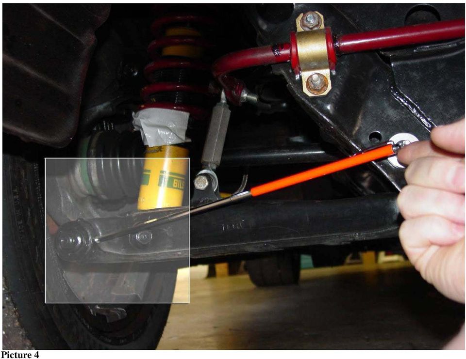
2 7.) I make the assumption that no parts are bent and you have used your thumb to get toe and camber where it looks ok. 2 of toe out or +3 camber on one wheel is what I mean, correct that NOW by eye, do not spend too much time on it. 8.) After each setting adjustment, bounce the car in place STOP, roll it 8-10 back then forward to where it was. NEVER, bounce again after you start rolling forward and always end your bounce going up, not down on the car. 9.) You have a factory manual and know how to use it for finding out the procedures needed to make the setup adjustments. 10.) Empty all fuel and put one gallon back in. 11.) Using a fish scale, and after all prep is done, I measure the car s resistance on a flat surface. Record what it takes to just roll the car. Later, as you do maintenance, compare the freshly prepared car to the after raced car. If you gain resistance, look to see if there is a reason for that gain (brakes, fluid break down, bearings etc ). Correct if you can keeping in mind that you might establish a new resistance number after the car has seen the track and become seated in. Regarding setup and especially for new builds this process below will not be very fun as you will chase yourself narrowing the gap of the different settings. You will find out that when you make a change to one setting, others may be altered. Be patient, the gap will lesson until it is right. It Begins Step #1 (Ride Height) Using the spring perches, adjust the ride height to 5-1\4 at the pinch weld on the bottom of the car at the rocker panel (see Picture 2 & 3). It is normal for the LR to have more threads showing on the bottom compensating for the driver s weight. This will take sometime as you get used to how the car moves on one corner while you adjust another. BE PATIENT, keep going back and forth till it is near perfect. Remember this step, you will be back here again many times. You will not be showing the same amount of threads corner to corner. Remember, the floor where your car sits AND where you measure from needs to be level!!! Step #2 (LR Toe and Camber) We now need to square the car up so we can run through the first of several settings adjustments. Remember those bolts I had you install, now is the time to use them. They are used to measure the lower control arm on the driver s side rear wheel verse the centerline of the car. Using a telescopic measuring device, adjust the lower cam bolts until the distance between the bolts you installed, front and rear, and the back of the outboard bushing flange of the lower control arm are the same, front and rear (see picture 4). You now have zero toe on that wheel and that wheel is pointing straight. While doing this wheel, go ahead and make the camber -2. You are adjusting the cam bolts anyway, this is what I like to do. Often, I do not have to touch this wheel again. JUST REMEMBER, if you get out of whack, set this wheel again and go from there, keep reading. Keeping this wheel square is vital to this process!!

3 Please Note: Steps #3 - #5 can be both time consuming and frustrating for the uninitiated. Iron Canyon Motorsports has recently released an ICM Alignment System to assist in stringing your Spec Miata. Visit for more information. Step #3 (LF Toe, Camber and Caster) Time to get that kite string and jack stands out. Adjust 2 stands where they are slightly above the center wheel hub height. Tie your string securely to the portion of the stands that is adjustable. Now make final corrections so the string is level with the center line of the wheel hubs and tight enough to not be drooping. Ok, the Miata is wider in the rear, this is a pain. You should now have a string tied to the stands with it level with the hubs centerline with the stands stretched out about 3 past the front and rear wheels string tight. Basically, you will see a string running along the side of your car connected to the stands. Move the stands around until you have a 1 gap on the LR between the string and the wheel lip front and rear of that wheel. Once this is done, you have aligned the string to the wheel that you already aligned to the chassis, coming together for you now? As you set toe and make other adjustments, you will have to continue to square up the string to the LR wheel. BUT, after we get further along, we will drop the string and use toe plates, stay with me. Move to the front left wheel, measure from the string to the wheel lip, front and rear of the wheel, and inline with the string. Since the rack is centered and locked down and you have that 1 gap on the rear, you are looking at how far the toe is off verse the centerline of the car. Adjust toe on the LF to zero. Of course, you will have to re-square your string each time you roll the car. While doing this corner, you are going to set your camber to -2, your caster to +3-5 (just make sure the other side matches on caster later). Once the toe is zero, and the other settings are correct, secure this corner but do not tighten all the way just yet. Step #4 (RR Toe and Camber) We now are going to move to the passenger side of the car. Dust off them toe plates, their up now. Start by using your toe plates to get the RR to zero toe. While there, you guessed it, set the camber to -2. Once you are done, move to the RF corner. Remember, tighten to keep form moving only, no need to gorilla it at this point. Step #5 (LF Toe, Camber and Caster) Use the toe plates to match the left side, just like you did in the rear. Set the caster and camber to match the left front. At this point, the car is aligned with the centerline of the car, our ride height is set and our settings are in basic form. I call this the pre-scale setup. Good for you, these cars are not that corky, meaning not much chasing compared to other types of race cars.

4 Step #6 (Scaling) I assume you have been on the scales this whole time, the extra height helps for all the floor work you needed to do. Some even setup their scales to coincide with a lift, that s great as long as you check everything to make sure it is square. First, let s record the total weight of the car. Add/subtract ballast now. Once it is where you are comfortable we can move on to the scaling. We will only be dealing with percentages not the actual weight numbers. We will never get the corners to even out AND have a level platform for the suspension. So, we change balance with percentages on this car. Percentage to total weight is a common feature on most scales (as everyone else in racing uses them too). This is what I will be referring to from here on out. Record the Cross (always defined as the left rear and right front to total) weight % Record the left to right % Record the front to rear % Trade offs have to be made so we will concentrate on Wedge (cross weight) while maintaining ride height. NOTE: If a car has 49% of CW (cross weight) it is considered de-wedged. If it has 51% CW it is considered wedged. De-wedge helps the car turn left while tightening up the balance on rights. Vise versa with 51% wedge. I ll explain it more later. The fun begins! You are either REAL lucky and have a 50% car, it happens, or you see a car that is wedged or de-wedged. Based on your CW %, you need to make adjustments to the spring perches. The following procedure is crucial, a must. Keeping the ride height the same is your friend on track and in doing this setup. Forget what your brain tells you, just do what I say for this part. If you are de-wedged (less that 50%) you need to do the following. Up on the LR & RF Down on the RR & LF Make the adjustments in equal turns up and down (from whole turns to quarter turns). This will increase the CW with hardly any ride height change. One round is about 1.2%, your car may differ. Get it exactly 50%, not 50.1 or 49.9, 50.00%. If you are wedged (more than 50%) you need to do the following. Up on the RR & LF Down on the LR & RF

5 Make the adjustments in equal turns up and down (from whole turns to quarter turns). This will decrease the CW with hardly any ride height change. One round is about 1.2%, your car may differ. Get it exactly 50%, not 50.1 or 49.9, 50.00%. Step #5 (the recheck) GO BACK OVER ALL SETTINGS! If anything is out, repeat all the above steps, something has changed. Keep going through the steps until your step #5 yields the numbers we are after with no adjustments needed. It might take a few times or you might be blessed with the racing gods and get it right the first time. Once it is right, it should also be TIGHT!!!!!! Make sure you measure LAST, not tighten last. Step #6 (completion) Once you are finished either because it is right or because you just gave up, we have more things to do. First, set the sway bars to full stiff up front and full soft in the rear, NO PRELOAD!! Then, remove the vise grips from the column and let the guy that has been sitting in the car this whole time get out or remove the weight you used to simulate your body weight. The car will not look right, with no driver the platform is not level, and that s GOOD. We now have the car sitting there with zero toe all four, -2 camber all four, +3-5 caster both fronts (but the same side to side), 50% CW AND sitting with driver at 5-1/4 pinch weld to ground. Next, I will tell you what I do at the track to tune this beast! BUT, I ve won many competitive races with this very setup and all but the last 3-6 tenths is capable with the settings above. Enjoy, hope it helps!

6 Picture 1

7 Picture 2

8 Picture 3

9 Picture 4
SLACK PERFORMANCE KARTS
 SLACK PERFORMANCE KARTS SET UP GUIDE Thank you for purchasing a 2013 Slack Axiom Chassis. Performance Mfg. strives to provide you with the very best chassis and components on the market today. Your satisfaction
LG G5 Chassis Brace Gen 5 Camaro THE MOST POWERFUL HEADERS ON THE PLANET Brought to you by LG Motorsports 972-429-1963
 LG G5 Chassis Brace Gen 5 Camaro THE MOST POWERFUL HEADERS ON THE PLANET Brought to you by LG Motorsports 972-429-1963 Thank you for purchasing LG Motorsports products for your Gen 5 Camaro. Parts Inventory:
S&W Race Cars and Components, Inc.
 S&W Race Cars and Components, Inc. 11 Mennonite Church Road Spring City, PA 19475 TECH & INFORMATION: 610-948-7303 ORDERS: 1-800-523-3353 OFFICE FAX: 610-948-7342 E-Z INFO FAX 610-792-1234 CAUTION!!! -
A Short Course on Wheel Alignment
 A Short Course on Wheel Alignment In its most basic form, a wheel alignment consists of adjusting the angles of the wheels so that they are perpendicular to the ground and parallel to each other. The purpose
MM Adjustable Tie-Rod Ends (MMTR-2, -4, -7)
") 3430 Sacramento Dr., Unit D San Luis Obispo, CA 93401 Telephone: 805/544-8748 Fax: 805/544-8645 www.maximummotorsports.com MM Adjustable Tie-Rod Ends (MMTR-2, -4, -7) PLEASE NOTE: The use of 1996-2004
3430 Sacramento Dr., Unit D San Luis Obispo, CA 93401 Telephone: 805/544-8748 Fax: 805/544-8645 www.maximummotorsports.com MM Adjustable Tie-Rod Ends (MMTR-2, -4, -7) PLEASE NOTE: The use of 1996-2004
Tonykart Chassis Setup Manual
 Tonykart Chassis Setup Manual Sprint Setup Chapter 1: Weight Distribution 1.1 Introduction 1.2 Seat Placement/Adjustment 1.3 Factors to check during weight distribution analysis 1.4 Adjusting Kart Weight
Tooling List 17mm Socket 17mm Wrench 24mm Wrench 26mm Wrench 3/8 Drive Ratchet Torque Wrench
 Thank you for purchasing the CorkSport Rear Adjustable Camber Arms. By replacing your OEM camber arms with the CorkSport Adjustable Camber Arms, you will be able to dial in your suspension with +/- 5 degrees
rarecorvettes.com, [email protected], (831) 475-4442 Pacific Time Zone
 475-4442 Pacific Time Zone") INTRODUCTION TO WHEEL ALIGNMENT A SHORT COURSE ON WHEEL ALIGNMENT, FRONT AND REAR PREPARED FOR THE N.C.R.S. NATIONAL CONVENTION JUNE 29 TO JULY 5, 2012 by: JOE CALCAGNO, RARE CORVETTES rarecorvettes.com,
INTRODUCTION TO WHEEL ALIGNMENT A SHORT COURSE ON WHEEL ALIGNMENT, FRONT AND REAR PREPARED FOR THE N.C.R.S. NATIONAL CONVENTION JUNE 29 TO JULY 5, 2012 by: JOE CALCAGNO, RARE CORVETTES rarecorvettes.com,
»Product» Safety Warning
 C1200 Installation Instructions 2007-2016 Chevy/GM 1500 2/4wd 2" Strut Spacer Lift Read and understand all instructions and warnings prior to installation of product and operation of vehicle. Zone Offroad
Street-Lynx. Reilly MotorSports, Inc. Installation Manual
 Street-Lynx By Reilly MotorSports, Inc. Installation Manual 1 1- Begin by removing your original rear suspension disconnect your brake lines, E-brake cables, and remove the driveshaft. To prevent fire
HOME ALIGNMENT OF PORSCHE 914 FOR COMPETITION OR STREET. Complete Step by Step Guide to Alignment
 HOME ALIGNMENT OF PORSCHE 914 FOR COMPETITION OR STREET Complete Step by Step Guide to Alignment How to adjust: A. Level and Rake Car p. 4 B. Camber p. 6 C. Caster p. 7 D. Toe p. 8 E. Corner Balance p.
6 inch A-Arm Lift Kit WARNING: 16-018/16-019. installation instructions. will fit CLUB CAR DS. included:
 Revised May 205 6-08/6-09 6 inch A-Arm Lift Kit will fit CLUB CAR DS installation instructions included: Rear Lift Blocks Main Suspension Assembly Spindles A-Arms Rear Shock Mounting Plates U-Bolts WARNING:
MEASURING WHEEL ALIGNMENT
 MEASURING WHEEL ALIGNMENT 2003-04 WHEEL ALIGNMENT Specifications & Procedures - Hummer - H2 Steering and vibration complaints are not always the result of improper alignment. One possible cause is wheel
Align it Right! How to properly align your GMC yourself right in your own driveway. By Jerry Work GMCWS rally Casa de Fruita, CA Spring 2012
 Align it Right! How to properly align your GMC yourself right in your own driveway By Jerry Work GMCWS rally Casa de Fruita, CA Spring 2012 TEXT & PHOTOS BY JERRY WORK EXCEPT AS NOTED Simple concepts,
INSTALLATION INSTRUCTIONS COMPETITION SERIES COILOVER SUSPENSION SYSTEM 03+ Scion xb
 INSTALLATION INSTRUCTIONS COMPETITION SERIES COILOVER SUSPENSION SYSTEM 03+ Scion xb NOTE: Progress Technology products should only be installed by a qualified licensed mechanic experienced in the installation
STEERING HANDLEBAR/FRONT WHEEL/ FRONT SHOCK ABSORBER
 14 14 STEERING HANDLEBAR/FRONT WHEEL/ SCHEMATIC DRAWING ------------------------------------------------- 14-1 SERVICE INFORMATION------------------------------------------------ 14-2 TROUBLESHOOTING-----------------------------------------------------
16 April 2012 1032011-F 1994-2002 Dodge Adjustable Track bar with Relocation Bracket 1
 16 April 2012 1032011-F 1994-2002 Dodge Adjustable Track bar with Relocation Bracket 1 BD Adjustable Track Bar w/bracket Dodge 2500-3500 4WD Models 1994-2002 Dodge 1500 4WD Model 1994-2001 P/N# 1032011-F
SELF-STEERING AXLE TABLE OF CONTENTS
 SELF-STEERING AXLE TABLE OF CONTENTS Section 1 - Introduction Section 2 - Pre-Installation Check List Section 3 - Ride Height Adjustments Section 4 - Suspension Mount Section 5 - Axle Mount Section 6 -
SCION tc 2005-2008 COIL OVER SUSPENSION Preparation
 SCION tc 2005-2008 COIL OVER SUSPENSION Preparation Part Number: PTR11-21070 NOTE: Part number of this accessory may not be the same as the part number shown. Kit Contents: Item # Quantity Reqd. Description
2011-14 F250 6 RADIUS ARM KIT
 92154000 Thank you for choosing Rough Country for your suspension needs. 2011-14 F250 6 RADIUS ARM KIT Rough Country recommends a certified technician installs this system. In addition to these instructions,
SECTION 2B WHEEL ALIGNMENT TABLE OF CONTENTS
 SECTION 2B WHEEL ALIGNMENT TABLE OF CONTENTS Description and Operation... 2B2 Four Wheel Alignment... 2B2 Toein... 2B2 Caster... 2B2 Camber... 2B2 Diagnostic Information and Procedures... 2B3 Tire Diagnosis...
SUSP-06, Torsion Bars - Removing, Replacing, and Indexing
 Introduction SUSP-06, Torsion Bars - Removing, Replacing, and Indexing Replacing the torsion bar on a 944 is not all that difficult. However, reindexing the torsion after completion is a pain and can be
Prepared by Graham from SuperPro August 2011
 Understanding di Steering and Wheel Alignment Angles Prepared by Graham from SuperPro August 2011 Remember:- Tyre Wear Patterns Tell The Technician A Story Provide Vital Information For Determining Final
LIFT-505. BMF Lift Kit. Yamaha Drive Gas or Electric. Installation Instructions
 LIFT-505 BMF Lift Kit Yamaha Drive Gas or Electric Installation Instructions Contents of LIFT-505 Yamaha Drive BMF Lift Kit: a (1 ea.) BMF A-Arm Assembly b (1 ea.) Driver Side Shock Tower c (1 ea.) Passenger
http://localhost/vida/jsp/information/xml/xmldocprintpreview.jsp
 Page 1 of 7 60: Wheel alignment V70 XC (01-) / XC70 (-07), 2001, B5244T3, AW50/51 AWD, L.H.D, YV1SZ58D811036138, 036138 5/4/2014 PRINT 60: Wheel alignment Wheel alignment, checking / adjusting Note! For
Model Year: 2010 Model: Prius Doc ID: RM000001Y3B015X. Title: ALIGNMENT / HANDLING DIAGNOSIS: FRONT WHEEL ALIGNMENT: ADJUSTMENT (2010 Prius)
") Last Modified: 5-3-2010 6.4 N From: 200904 Model Year: 2010 Model: Prius Doc ID: RM000001Y3B015X Title: ALIGNMENT / HANDLING DIAGNOSIS: FRONT WHEEL ALIGNMENT: ADJUSTMENT (2010 Prius) ADJUSTMENT If the
Last Modified: 5-3-2010 6.4 N From: 200904 Model Year: 2010 Model: Prius Doc ID: RM000001Y3B015X Title: ALIGNMENT / HANDLING DIAGNOSIS: FRONT WHEEL ALIGNMENT: ADJUSTMENT (2010 Prius) ADJUSTMENT If the
Ford F-250 / 350 2-1/2 Coil Kit. Ford F-250, F350 2011-2015. Part#: 013255
 Part#: 013255 Ford F-250 / 350 2-1/2 Coil Kit Ford F-250, F350 2011-2015 Rev.040815 491 W. Garfield Ave., Coldwater, MI 49036. Phone: 517-279-2135 Web/live chat: www.bds-suspension.com. E-mail: [email protected]
CorkSport Mazdaspeed 6 Rear Sway Bar 2006-2007 Mazdaspeed 6
 CorkSport Mazdaspeed 6 Rear Sway Bar 2006-2007 Mazdaspeed 6 Pre-Installation Notes: The CorkSport Rear Sway Bar is a great addition to improving the handling performance to the Mazdaspeed 6. It will minimize
ReadyLift (Part# 66-5075) Strut Extension, Installation Instructions Toyota Tundra New Body Style 2WD & 4WD
 Strut Extension, Installation Instructions Toyota Tundra New Body Style 2WD & 4WD") SAFETY WARNING: recommends this system be installed by a professional technician. In addition to these instructions, professional knowledge of disassembly/ reassembly procedures and post installation checks
SAFETY WARNING: recommends this system be installed by a professional technician. In addition to these instructions, professional knowledge of disassembly/ reassembly procedures and post installation checks
INSTALLATION INSTRUCTIONS. 6111 Air Spring Kit 2011+ Ford F250/F-350 Single Wheel 2WD 2011+ Ford F350 Dually 2WD IMPORTANT NOTES
 INSTALLATION INSTRUCTIONS 6111 Air Spring Kit 2011+ Ford F250/F-350 Single Wheel 2WD 2011+ Ford F350 Dually 2WD Thank you for purchasing a quality Hellwig Product. PLEASE READ THIS INSTRUCTION SHEET COMPLETELY
MUSTANG II IFS COMPLETE PARTS PACKAGE
 MUSTANG II IFS COMPLETE PARTS PACKAGE Your Southern Rods & Parts Mustang II IFS Parts Package contains the following items: 1 pr) Upper Control Arms (2023) 1) Upper Arm Bolt Kit (MP-001-A) 1 pr) Lower
AIR-SUSPENSION. Art. nr.: L.L200.07.C.M. Auxiliary Air Suspension. Designed for: Mitsubishi L200. From: 2007& UP RDW 71/320-0569
 AIR-SUSPENSION Dunlop Systems and Components Het Wegdam 22 7496 CA Hengevelde The Netherlands Tel.: +31-547-333065 Fax: +31-547-333068 Website: www.dunlopsystems.com Art. nr.: L.L200.07.C.M Designed for:
Understanding Wheel Offset and Backspacing
 Understanding Offset and Backspacing Proper service and repair procedures are vital to the safe, reliable operation of all motor vehicles as well as the personal safety of those performing the repairs.
FRONT SUSPENSION Click on the applicable bookmark to selected the required model year
 FRONT SUSPENSION 33A-2 FRONT SUSPENSION General Information GENERAL INFORMATION 33200010105 The front suspension on 2WD vehicles is an independent suspension system having the double wishbone combined
What is Camber, Castor and Toe?
 What is Camber, Castor and Toe? Camber is probably the most familiar suspension term to owners. It is the angle of the wheels relative to the surface of the road, looking at the car from the front or rear.
Installation Guide for the TJ LCG PRO Suspension System (Low Center of Gravity) Available 4 or 5
 Available 4 or 5") INSTALLATION GUIDE Installation Guide for the TJ LCG PRO Suspension System (Low Center of Gravity) Available 4 or 5 Take every precaution to make this installation a safe procedure. Make safety the number
INSTALLATION GUIDE Installation Guide for the TJ LCG PRO Suspension System (Low Center of Gravity) Available 4 or 5 Take every precaution to make this installation a safe procedure. Make safety the number
TUTORIAL. REbUILdING. front CALIpER O-RING CONVERSION CORVETTE 1965-82. Part #: HT-1
 Part #: HT-1 1965-82 CORVETTE O-RING CONVERSION front CALIpER REbUILdING TUTORIAL Choosing a Brake Caliper Rebuild Kit Standard Lip Seals vs. O-Ring Seals Lip seal design seals are used on 1965-1982 Corvette
UNDERSTANDING CHASSIS ADJUSTMENTS
 UNDERSTANDING CHASSIS ADJUSTMENTS There was once a time not so long ago when the "average" racer could arrive at the track with his "average" set-up and with minor adjustments, he could run competitively.
SUSPENSION DIAGNOSIS
 SECTION 2A SUSPENSION DIAGNOSIS TABLE OF CONTENTS Diagnosis... 2A-2 General Diagnosis... 2A-2 Hub and Bearing... 2A-7 2A-2 SUSPENSION DIAGNOSIS DIAGNOSIS GENERAL DIAGNOSIS Problems in the steering, the
WHEEL ALIGNMENT 4WD SA 6
 SA6 WHEEL ALIGNMENT 4WD 1. MAKE FOLLOWING CHECKS AND CORRECT ANY PROBLEMS (a) Check the tires for wear and proper inflation. Cold tire inflation pressure: See page A25 (b) Check the wheel runout. Lateral
Mustang CoolRide. Installing Air Ride Technologies CoolRide air suspension in 1979-2002 Mustangs. by Doc Frohmader
 Installing Air Ride Technologies CoolRide air suspension in 1979-2002 Mustangs by Doc Frohmader I still remember the first Mustangs. They were, for the time, relatively sophisticated and high-tech. Since
Service Bulletin Trucks Date Group No. Page
 Volvo Trucks North America, Inc. Greensboro, NC USA Replaces Service Bulletin 601 06 dated 03.98. Service Bulletin Trucks Date Group No. Page 9.2000 601 006 1(8) Wheel Alignment Steer and Drive Axles VN,
TUTORIAL. REbUILdING. REAR CALIpER O-RING CONVERSION CORVETTE 1965-82. Part #: HT-2
 Part #: HT-2 1965-82 CORVETTE O-RING CONVERSION REAR CALIpER REbUILdING TUTORIAL Choosing a Brake Caliper Rebuild Kit Standard Lip Seals vs. O-Ring Seals Lip seal design seals are used on 1965-1982 Corvette
STEADYfast Stabilizer Installation Notes Fifth Wheel and Travel Trailers 11/23/13
 STEADYfast Stabilizer Installation Notes Fifth Wheel and Travel Trailers 11/23/13 (See Supplemental Instructions for trailers with heavy duty round footplates and/or Power Leveling Systems) PHONE SUPPORT
2. This is a close up of a typical area where the rocker is rusted out leaving holes under where the rocker moulding would be..
 ROCKER PANELS 55,56,57 CHEVY REPLACEMENT Do not throw away any pieces when you first remove them. There are many supports that are not reproduced and will need to be used again. When disassembling try
92-00 Civic/ 94-01 Integra/ 93-97 Del Sol/ 92-95 CRX Rear Kit Part No. 75540
 92-00 Civic/ 94-01 Integra/ 93-97 Del Sol/ 92-95 CRX Rear Kit Part No. 75540 www.airliftperformance.com MN-514 (06409) NPR 4762 Please read these instructions completely before proceeding with installation
Verify caster, camber and toe-in are correct before proceeding.
 If rotating the tie rod end 360 degrees changes the toe-in too much, use the rack tie rod to make smaller adjustments. Put the tie rod end in the steering arm and snug the castle nut before adjusting.
WHEEL ALIGNMENT SPECIFICATIONS & PROCEDURES
 WHEEL ALIGNMENT SPECIFICATIONS & PROCEDURES 1998 Mitsubishi Montero 1997-98 WHEEL ALIGNMENT Mitsubishi - Specifications & Procedures Diamante, Eclipse, Galant, Mirage, Montero, Montero Sport, 3000GT RIDING
Technical Service Bulletin
 Subject FOUR WHEEL ALIGNMENT - EZ CAM TM XR CAMBER ANGLE ADJUSTING BOLTS Date Model [X] PARTS MANAGER JANUARY, 2008 2003-2008 TIBURON [X] TECHNICIAN CIRCULATE TO: [ ] GENERAL MANAGER [X] SERVICE ADVISOR
WHEEL ALIGNMENT SPECIFICATIONS & PROCEDURES
 WHEEL ALIGNMENT SPECIFICATIONS & PROCEDURES 2001 Chevrolet Camaro 2000-01 WHEEL ALIGNMENT Specifications & Procedures Cars - Except Saturn IDENTIFICATION MODEL IDENTIFICATION Body Code (1) Model "C"...
READ AND UNDERSTAND ALL INSTRUCTIONS AND WARNINGS PRIOR TO INSTALLATION OF SYSTEM AND OPERATION OF VEHICLE.
 491 W. Garfield Ave., Coldwater, MI 49036 Phone: 517-279-2135 Web/live chat: www.bds-suspension.com E-mail: [email protected] Product: GM Leaf Spring READ AND UNDERSTAND ALL INSTRUCTIONS AND
Hydraulic Steering Install
 Hydraulic Steering Install Disclaimer: The following is a tutorial on how to install hydraulic steering in a center console boat. I am not a mechanic. I am not a photographer. I am a guy who had a steering
Owner s Manual Read and keep this manual. Patents World Wide
 Owner s Manual Read and keep this manual. Patents World Wide S & S Industries, Inc., Sarasota, FL, USA www.trail-gator.com Copyright 2008 All Rights Reserved The following manual is provided to assist
Owner s Manual Gantry Cranes
 Owner s Manual Gantry Cranes Fixed Height Gantry Crane MODEL NUMBER: SERIAL NUMBER: CAPACITY IN TONS: Telescoping Gantry Crane Bushman AvonTec 262-790-4200, 800338-7810, Fax 262-790-4200 www.bushmanavontec.com
INSTALLATION INSTRUCTIONS. 6108 Air Spring Kit 2011+ Ford F250 Single Wheel 4WD 2011+ Ford F350 Dually 4WD (2011 F350 Single Wheel 4WD use p/n 6113)
") INSTALLATION INSTRUCTIONS 6108 Air Spring Kit 2011+ Ford F250 Single Wheel 4WD 2011+ Ford F350 Dually 4WD (2011 F350 Single Wheel 4WD use p/n 6113) Thank you for purchasing a quality Hellwig Product. PLEASE
INSTALLATION INSTRUCTIONS 6108 Air Spring Kit 2011+ Ford F250 Single Wheel 4WD 2011+ Ford F350 Dually 4WD (2011 F350 Single Wheel 4WD use p/n 6113) Thank you for purchasing a quality Hellwig Product. PLEASE
Pole Lathe and Shave Horse Design
 Pole Lathe and Shave Horse Design These pictures and accompanying words are Copyright Michael Hughes February 2002. They are not to be re-produced, in part or whole, without permission from the author.
Make sure all tubes are installed to your satisfaction BEFORE finish welding!!
 INTRODUCTION: This S&W Roll Bar or Roll Cage performs both a safety and performance function. As a safety device, the main hoop of the cage protects the driver from impact. The rear braces and side bars
Your New Frog Bike. Congratulations on purchasing a new bike and thank you for choosing Frog!
 Your New Frog Bike Congratulations on purchasing a new bike and thank you for choosing Frog! We know that you must be raring to go but before you do there s a few little things still to do to get you up
2016 Price Sheet. Custom Built Replacement Chassis
 2016 Price Sheet Custom Built Replacement Chassis 5557 Chevy Car Direct Replacment Chassis 15,895 5362 Corvette Direct Replacment Chassis 15,895 5557 Chevy Car Pro Street Chassis 16,895 5362 Corvette Pro
Little British Car Co.
 Little British Car Co. 29311 Aranel, Farmington Hills, MI 48334-2815, USA Tel: 248 489 0022 or 800 637 9640 Fax: 248 489 9665 On the web at: www.lbcarco.com E-mail: [email protected] MGB Tube Rear Shock
Competition 4 & 6 suspension Lift Toyota Landcruiser & nissan patrol
 Competition 4 & 6 suspension Lift Toyota Landcruiser & nissan patrol Competition suspension Product Guidelines Guidelines for sale and recommendation of 4 (100mm) and 6 (150mm) Lifts for Toyota Landcruiser
How to Set Up Corvette IRS Rear Camber (basic do-at-home version)
") How to Set Up Corvette IRS Rear Camber (basic do-at-home version) by Lars Grimsrud Colorado Corvette Crazies (CCC) The Ultimate Corvette Tuning & Beer Drinking Fraternity Lafayette, CO Rev. B 3-24-05 This
How to Set Up Corvette IRS Rear Camber (basic do-at-home version) by Lars Grimsrud Colorado Corvette Crazies (CCC) The Ultimate Corvette Tuning & Beer Drinking Fraternity Lafayette, CO Rev. B 3-24-05 This
Ford F-Series Column Shift Repairs
 Ford F-Series Column Shift Repairs I ve had it on my list to tighten up the linkage on my 52 s column shift setup for a long time. I tried to get it apart when I had all the front end sheet metal off,
BUGGY SETUP GUIDE. Volume GOKARTSUSA GY6 150, CN250. Buggy Setup Guide
 BUGGY SETUP GUIDE Volume 1 GOKARTSUSA GY6 150, CN250 Buggy Setup Guide GY6 150, CN250 DUNE BUGGY Buggy Setup Guide GOKARTSUSA.COM 2000 Highway 50 S. Lake Tahoe, CA 96150 Phone 800.603.1437 2 Table of Contents
WARNING TO END USER, INSTALLER AND SELLER OF THIS PART!
 WARNING TO END USER, INSTALLER AND SELLER OF THIS PART! By installing this part you are accepting full responsibility and liability for proper wheel and tire fitment after installation. It is the installer
family games Taking the kids swimming is a great way of making sure they re moving around and having fun. And to help you get them into
 swim family games Taking the kids swimming is a great way of making sure they re moving around and having fun. And to help you get them into the pool, we ve come up with loads of great swimming games to
TL-12 Passenger Car Alignment System
 Operation and Service Manual Laser Guided Wheel Alignment System TL-12 Passenger Car Alignment System 8231 Blaine Road Blaine, WA 98230 360-371-0552 360-371-0553 fax 800-496-3777 toll free www.tru-line.net
INTRODUCTION KINGPIN REPLACEMENT
 KINGPIN REPLACEMENT Author: Randy Baumann All information, illustrations and specifications are based on the best information available at the time of publication. The author cannot guarantee the accuracy
Table of Contents. Suspension Systems
 Table of Contents Subject Page Purpose of the System... 3 Basic Suspension Geometry... 4 Caster...4 Camber...5 Toe...6 Steering Roll Radius...7 Steering Axis Inclination....8 Toe-out on Turns...9 Geometric
(A4) Suspension and Steering Sample Questions and Answers
 Suspension and Steering Sample Questions and Answers") (A4) Suspension and Steering Sample Questions and Answers Answers to these questions are found beginning on page 4 of this document 1. Two technicians are discussing the replacement of an inner tie rod
(A4) Suspension and Steering Sample Questions and Answers Answers to these questions are found beginning on page 4 of this document 1. Two technicians are discussing the replacement of an inner tie rod
...and for choosing Rocker BMX, you have chosen wisely. We appreciate the market is slightly clouded with various brands of so called mini bmx.
 ...and for choosing Rocker BMX, you have chosen wisely. We appreciate the market is slightly clouded with various brands of so called mini bmx. However, Rocker is very different from other brands; it was
MGB Chrome Bumper Conversion
 MGB Chrome Bumper Conversion Installation Instructions For 1974 1/2-1980 MGB This kit requires cutting, welding, and painting. Professional installation recommended. Note: Every MGB body is slightly different
Complete Dovetail Jig Instructions
 Complete Dovetail Jig Instructions 18 15 1 12 13 8 (22818) 19 17 16 4 3 6 14 5 9 9 11 10 2 PARTS LIST - COMPLETE DOVETAIL JIG Introduction Your new dovetail jig will cut Full Through Dovetails and three
Installation Instructions
 May 2, 2016 1967-1969 Camaro and 1968-74 Nova Complete Sub Frame Installation Instructions The following instructions are intended for professional installers and are guidelines only. Speedtech Performance
TRANS-05, Torque Tube Removal, Rebuilding, and Installation
 TRANS-05, Torque Tube Removal, Rebuilding, and Installation Tools Metric Wrench Set Metric Socket Set Jack Stands (6 minimum) Floor Jack 8mm Cheesehead socket (also referred to as 12 point internal socket
SUSPENSION AND STEERING OVERVIEW
 SUSPENSION SUSPENSION AND STEERING OVERVIEW The S40/V50 has a wide track and a long wheelbase for its relative size and weight. This gives the car stable and predictable driving characteristics. It also
BEE LINE COMPANY TOTAL VEHICLE WHEEL ALIGNMENT AND THE BENEFITS OF CAMBER CORRECTION
 BEE LINE COMPANY TOTAL VEHICLE WHEEL ALIGNMENT AND THE BENEFITS OF CAMBER CORRECTION 2700 62nd Street Court, P.O. Box 130 Bettendorf, Iowa 52722 Phone: 800-728-7828 Fax: 563-332-6517 Website: www.beeline-co.com
9,000lb capacity 4 Post Lift Installation Manual
 9,000lb capacity 4 Post Lift Installation Manual Parts Checklist 1 Main side track with 9/16 hole on cylinder end complete with cylinder, hose and connector 1 Offside track 2 Cross Rails pre-assembled
Do-It-Yourself- Hydraulic Press Make Your Own, by Marshel Rossow
 Do-It-Yourself- Hydraulic Press Make Your Own, by Marshel Rossow This press can be built from readily available metal. Materials and dimensions need not be exactly what is shown here. Much of the material
Installation manual. 1.75 front leveling kit. 2011 Dodge Durango 2011-2014 Jeep Grand Cherokee. Part # 42006. Part # 42006
 Installation manual 1.75 front leveling kit 2011 Dodge Durango 2011-2014 Jeep Grand Cherokee Part # 42006 sj02282011rev.01 Part # 42006 2011-2014 Dodge Durango 2011 Jeep Grand Cherokee 1.75 front leveling
TIRE BASICS TIRE MOUNTING AND DEMOUNTING
 Tire mounting and demounting can be dangerous and should only be performed by a trained tire specialist using proper tools and procedures. Be sure to review your training manual and refer to the RMA wall
Installation manual. 3 suspension system. 2009-2013 Ford F150. Part # 23000. Part # 23000. Important customer information: 2009-2013 Ford F150
 Installation manual 3 suspension system 2009-2013 Ford F150 Part # 23000 sj12112012rev.03 Part # 23000 2009-2013 Ford F150 3 suspension system Part # Description Qty. 23000-01 Driver side upper control
TJ Quick Disconnect Instructions
 1 TJ Quick Disconnect Instructions www.teraflex.com Kit #17012 Kit #17092 Kit #17010 Kit #17090 Important Notes: Prior to beginning this or any installation read these instructions to familiarize yourself
BUILDINGA 1/10 SCALE FLATBED TRAILER
 VOLUME 1, ISSUE 1 BUILDINGA 1/10 SCALE FLATBED TRAILER BUILT, DESIGNED & WRITTEN BY NATHAN MYERS MATERIALS: FEATURES: While the design was kept simple to allow anyone to be able to build their own trailer,
Gravity Racing Challenge STEM Team Competition Open Class High School Division Car Assembly Plans And Rules
 Gravity Racing Challenge STEM Team Competition Open Class High School Division Car Assembly Plans And Rules 1 Table Of Contents Introduction...Page 3 Floorboard...Page 4 Step One Steering Stop Installation...Page
4.5 LIFT BOX KIT 2009 2013 DODGE RAM 2500 & 3500 4WD DIESEL ENGINE ONLY FTS23031
 4.5 LIFT BOX KIT 2009 2013 DODGE RAM 2500 & 3500 4WD DIESEL ENGINE ONLY FTS23031 Fabtech Motorsports 4331 Eucalyptus Ave. Chino, CA 91710 Tech Line 909-597-7800 Fax 909-597-7185 Web www.fabtechmotorsports.com
Installation manual. 2.5 suspension system. (Except Mega-Cab) Part # 32102. Part # 32102. Important customer information:
 Part # 32102. Part # 32102. Important customer information:") Installation manual 2.5 suspension system 2009-2016 Dodge Ram 1500 4WD (Except Mega-Cab) Part # 32102 sj02272013rev.01 Part # 32102 2009-2016 Dodge Ram 1500 4WD (Except Mega-Cab) 2.5 Suspension System
Installation manual 2.5 suspension system 2009-2016 Dodge Ram 1500 4WD (Except Mega-Cab) Part # 32102 sj02272013rev.01 Part # 32102 2009-2016 Dodge Ram 1500 4WD (Except Mega-Cab) 2.5 Suspension System
DO NOT attempt to repair hub and wheel bearing assembly.
 Page 1 of 6 HUB & WHEEL BEARINGS (WITH PULSE VACUUM HUBLOCK) DO NOT attempt to repair hub and wheel bearing assembly. Removal DO NOT remove hub lock assembly by prying on hub lock legs. This can crack
1993 SUSPENSION Volkswagen Front. EuroVan
 Article Text ARTICLE BEGINNING 1993 SUSPENSION Volkswagen Front EuroVan DESCRIPTION FWD independent suspension is an double-wishbone type with torsion bars mounted on upper control arm. Wheel is supported
PERFORMANCE WHEEL ALIGNMENT
 Incorrect wheel alignment conditions affect tire wear and can cause drifting and/or pulling during cruise, acceleration and braking, plus poor directional control. For the performanceminded customer, the
PlaneWave CDK Telescope Instructions CDK12.5, 17, 20 and 24
 PlaneWave CDK Telescope Instructions CDK12.5, 17, 20 and 24 V112712 1 Collimation and Secondary Spacing Procedure The CDK optical design has four optical elements shown in Figure 1. The primary mirror
FRONT WHEEL ALIGNMENT
 66 RONT SUSPNSION DJUSTMNT. INSPCT TIR (S P 8) 60I50 ront: Rear:. MSUR VHICL HIHT Vehicle height: ront ( ) Rear (D C) 95 mm (3.74 in.) 6 mm (.44 in.) Measuring points: : round clearance of front wheel
OPTO-PLUS 204. Type DSX2
 1 OPTO-PLUS 204 Type DSX2 OPTO-ELECTRONIC LASER ALIGNER Operators manual 2 Operators manual for OPTO-PLUS wheel aligner Model 204 Type DSX2 (Dual Sensor Doubble Laser) INDEX Accessories and specifications
Kriya for Negative Mind
 Kriya for Negative Mind Bron: The Ten Light Bodies of Conciousness van Nirvair Singh Khalsa So So So So Hung Hung Hung Hung 3 MINUTES. Let s start with this pranayam. It s going to be a 4:4 breathing pattern.
Formula World GT 200 DRAFT COPY WWW.TEAMSPEEDMERCHANT.COM. f200.0.0d
 DRAFT COPY WWW.TEAMSPEEDMERCHANT.COM f200.0.0d 2 Introduction, Supplies and Additional Equipment Congratulations on your purchase of a Speed Merchant Formula World GT 200 competition chassis. This instruction
4 & 6 High Clearance Suspension System. Dodge 1500 4WD 2006-2011. Part#: 022605
 Part#: 022605 4 & 6 High Clearance Suspension System Dodge 1500 4WD 2006-2011 Rev. 091814 491 W. Garfield Ave., Coldwater, MI 49036. Phone: 517-279-2135 Web/live chat: www.bds-suspension.com. E-mail: [email protected]
UNPACKING AND ASSEMBLY
 UNPACKING AND ASSEMBLY Assembly Instructions Step 1. Open the two boxes and remove all the parts. Lay out the parts as shown below and read through the assembly instructions before beginning assembly.
For maximum effectiveness and safety, please read this Owner's Manual before using your Torso Track 2.
 For maximum effectiveness and safety, please read this Owner's Manual before using your Torso Track 2. TABLE OF CONTENTS Introduction...2 Important Safety Tips...3 Product Specifications...4 Set Up...5-6
Basic Stretch Programme 3. Exercise Circuit 4
 Basic Stretch Programme 3 Exercise Circuit 4 2 1 Calves Stand approximately 1 metre away from wall with legs straight and heels on floor. Step and lean forward and slowly push hips towards wall. Should