YuanDong SkyHawk Engine Parts Kit:
|
|
|
- Randall Lane
- 9 years ago
- Views:
Transcription
1 PLEASE READ THESE INSTRUCTIONS BEFORE INSTALLATION WEB SITE REFERENCE: Instructions Copy Righted: Rev. Dec 1, 2011 YuanDong SkyHawk Engine Parts Kit: GT2A > 1.4Kw 48cc / 40mm x 38mm bore and stroke: Square Head. 203 crankshaft brgs. GT2B > 1.4Kw 48cc / 40mm x 38mm bore and stroke: Round Head. 202 crankshaft brgs. GT5 > 1.6Kw 66cc / 47mm x 38mm bore and stroke: Square Head; 202 crankshaft brgs. Kit Box Contents: Due to many kit options and rules of different countries contents may vary: 2 cycle crankcase scavenging gas/oil mix engine with 2 point fixed mounting; Exhaust muffler; Tear Drop 2.5L Fuel Tank plated inside; Drive chain; Chain guard; Sprocket with 9 hole mounting hardware for 36 spoke wheel; Chain idler; Push button clutch lever, Carburetor; CD Ignition, Twist throttle with kill switch: Control cables; Tool kit with extra service parts; ( To ensure reliable engine performance: DO NOT use other than original SkyHawk replacement parts.) Note: Mechanical aptitude and experience is required to perform this installation. Many Do It Yourself mechanics will find this project rewarding. A love of small engines is the only requirement for this project. However, installation is sometimes best done by a professional auto or motorcycle mechanic. Frame size should be 28mm to 30mm dia. with 70 degree included V angle. For sufficient engine clearance select a bike with a seat tube length of at least 12 ½ inches measured between bottom of top tube and top of pedal sprocket tube. A rewarding joy and challenge is found in designing a custom installation of your own. Remember, a quality installation is paramount to safe usage and long term satisfaction. You may find many other uses for this engine kit such as for stationary machine power or 4 wheeled off road riding machines. Have fun and good luck on your motorized project. STEP #1 Mounting the Engine: 1. The engine mounts in a Vee frame. It is best to make sure all 4 engine studs are securely bottomed out in the engine before mounting. Use a Jam nut procedure to tighten. 2. Consider using Masking or Duct Tape on the front down-tube & seat tube of your bicycle to protect the paint finish while test fitting the engine to your donor bike. If the distance between the two frame tubes exceeds the engine mounting span then additional spacers or welded brackets may be required. Mount the engine to the seat tube first and then fit to the front tube. If frame tube fit is smaller than engine clamp dia. use strip shims to fit. See examples of Ft Mt installation on a big downtube bike frame.. 1

2 Big dia. downtube Front Mounting Ideas you can make or buy: a.) Flat Plate with Single U Bolt: b.) Dog leg plate and single U bolt: c.) Curved Plate with dual U bolt: d.) Welded on Pedestal mount design. d.) Pedestal front mount with rubber cushion for weld on application; Rubber wrap should also be used to isolate the rear mount on the seat tube if an alum. frame is used. 2

3 Figure 1. Bike with wide frame or big down tube: Use ¼ thick 1-1/8 x 2-1/2 steel plate with one hole in the center for a bolt to go through a drilled hole in tube frame and two holes for cap screws to go into engine block. Additional spacers maybe required depending on the donor bike. Figure # 1 3. If the rear frame tube from the seat down to the pedal sprocket is too small to fit the rear engine mount, a rubber shim can be made from an old bicycle rubber inner tube. This also helps reduce engine vibration. Engine needs to have the carburetor set in a level position. Too much engine tilt can cause chain to hit the drive cover and engine to not run correctly. It is best to have the drive chain to rear wheel sprocket be as horizontal as possible with no more than 15 degrees max engine tilt. After the desired engine location is determined mount the engine to frame. Appling LocTite thread lock is recommended to avoid loosening due to vibration. Note: All threads are metric. Chain Wheel Sprocket Installation: The Drive Chain Sprocket has a 36.9 mm dia. center hole and mounts on axel hub on the left side of the rear wheel against the spokes dish side in. The sprocket must fit over the hub in a perpendicular plane with the axle. This insures that your rear chain sprocket spins true with the rear bike wheel. *NOTE: On some older bike axle hubs like on coaster brake models it may be required to slightly enlarge the sprocket center hole to obtain a flush, and concentric fit next to the spokes. This is best done on a engine lathe by a professional machinist... It is also recommended that the rear wheel be re-spoked to 12 ga. spoke wires to insure long life. Most any Bike shop can do this operation for you. Applying thread adhesive and equal tightening of the sprocket bolts. This keeps the chain sprocket true with axle and free from wobble while spinning. With bike upside down spin wheel and check sprocket for wobble. The chain can jump off the sprocket if the sprocket installation is done incorrectly 1. Place rubber isolator next to spokes and locate sprocket on axel hub with curved side next to spokes, shinny side in. Cut the rubber isolator ring between holes in order to fit INSIDE the spokes and around the axle. Install the 5 split steel retainer plates 3 in and 2 out next to the rubber isolator and insert 9 bolts. 2. Secure with 9 bolts compressing the chain sprocket to the spokes. Note: Rubber isolators may be needed on both sides or on one side of sprocket for chain alignment, install as required: 3. The Chain Sprocket on the Wheel must align within 1/2 cm to the Chain Sprocket on the Engine. 3

4 Place Sprocket s bright chrome side inward next to spokes with teeth outward: 5 Steel plates: grade m6 bolts with lock nuts 2 rubber cushions. 3 plates Figure #2 1. Slice cut 2 Rubber Isolator Rings and install on both sides of spokes. 2. Install 9 hole Chain Wheel Sprocket mounted with shinny concave side inward: 3. Install three 1/3 plates first and then the two ½ Moons on top to form a lock.. Options available from your dealer: ½ moon plates Model #2 HD axle kit: Chrome Tank Chrome parts Z Tube intake The drive chain can be easily shortened to the correct length. Special tools are required to remove and replace the master link when shortening the chain by removing links. Ideally, both your pedal drive chain and your engine drive chain should have the same tension. A. Remove left rear cover plate from engine. This is the plate next to and under the clutch swing arm. B. MASTER LINK B Your engine may come with a standard bike chain or with a Heavy Duty 415 chain depending on how it was ordered by your dealer. Engine drive sprockets are different depending on chain size. The 415 chain uses a wide drive sprocket and the std. bike chain uses a narrow one. A 415 chain will work with a narrow sprocket but a std. bike chain will not go over a wide 10T drive sprocket. Note: Install chain with 4

5 master link clip on outboard side of the primary drive sprocket teeth. ( Note: wide tires larger than may rub on a wide 415HD chain: ) C. Use supplied spark-plug wrench to turn engine crankshaft sprocket to feed chain around it. Do not pry sprocket with a screwdriver or similar object. D. Fit chain, measure and remove excess links to assure proper length. Be sure master link connection rides on the inboard side of the primary drive sprocket or interference of link and sprocket can occur. Proper chain length is when top chain has ¼ inch to ½ deflection with the bottom side of the chain loop tight. E. Chain tension adjustments can be made by pulling rear wheel back if frame has straight slot wheel drop out. If both chains can be adjusted equally then installing chain idler on the wheel strut may not be necessary. At installer s discretion the chain idler can be installed on either the pedal chain or engine drive chain. F. Install supplied chain safety guard by attaching to engine and wheel axle struts. Ignition Coil and Engine Kill Switch installation A) Mount CD ignition coil on bike frame, close enough to attach coil wire to spark plug. Mount as far away from exhaust pipe as possible to avoid heat damage to semiconductors in CDI module. B) Attach CD ignition coil wires to same identical color coded wires coming from engine. C) Install Engine Kill Switch Wire on throttle to white wire coming from engine. Install the other wire with eyelet to a good frame ground not on paint. This will ground ignition and stop the engine when the kill button switch is activated. D) Route all wires away from engine exhaust heat. Secure wires with a plastic tie straps. *!WARNING! Operation of engine without stop or kill switch installed could result in personal injury if an emergency stop is required! The only alternate non recommended way of killing the engine is by releasing the clutch lever with bike brakes on and engine at slowest idle. 2008/ Catalytic muffler; Throttle with kill swt. CDI ign. CNS YD Carb. Speed Carb. Push button Clutch lever: Optional Dual lever Clutch & Brake Clutch cable end locks in lever handle. Clutch cable installation and adjustment: A) Install clutch lever to left side of handlebar and attach cable end barrel into lever slot hole. B) Squirt oil down the cable sleeve: Route clutch cable through the ball-mount on motor with the big spring around the cable jacket and ahead of the ball mount. The big spring serves as a cable heat shield. 5

6 C) Insert cable wire through small spring and route through clutch arm and attach brass cable-end and screw. Adjust cable tension to allow very slight play in arm. Handlebar clutch lever must be in the released or outward position to complete this operation. D) Activate lever a few times, and check clutch arm for slight free play: About 1/16 engine clutch arm free play is required with the handle bar lever in the released in what is called clutch engaged position or the engine will fail to start if cable is too loose or if too tight. Re-adjust as required. E) Basics of clutch operation: The handlebar lever pulls the cable that moves the engine clutch arm. In turn the clutch arm pushes a rod through the motor that pushes the clutch plate out. ( similar to a car clutch.) Releasing the handle bar lever engages the clutch and provides engine torque to the drive chain or to start the engine. The clutch friction allows engine to start, and also transmits engine torque to the drive chain. When the bike is in the pedal mode the handle bar clutch lever is locked inward in the catch notch. The bike then operates in default as it would without any engine. Periodic clutch adjustment is necessary to maintain efficient operation *NOTE: Cut off excess cable from clutch arm, before operation, to avoid possible interference with pedals, chain, your legs, etc. See Figure #4. Clutch arm: 1/16 free play: Clutch cable Note brass screw lock at the end; Figure #4 Additional cable adjustment can be made at mid joint if your kit has this. NOTE: If Clutch cable is not adjusted correctly the engine will not start. Check for 1/16 clutch cable arm free play with handle bar lever released. Carburetor and Throttle Installation OPTIONAL NEW STYLE THROTTLE with kill switch: Kill switch; one wire goes to white wire from engine and the other to frame grd. Drill small hole in handle bar for pin lock. 6

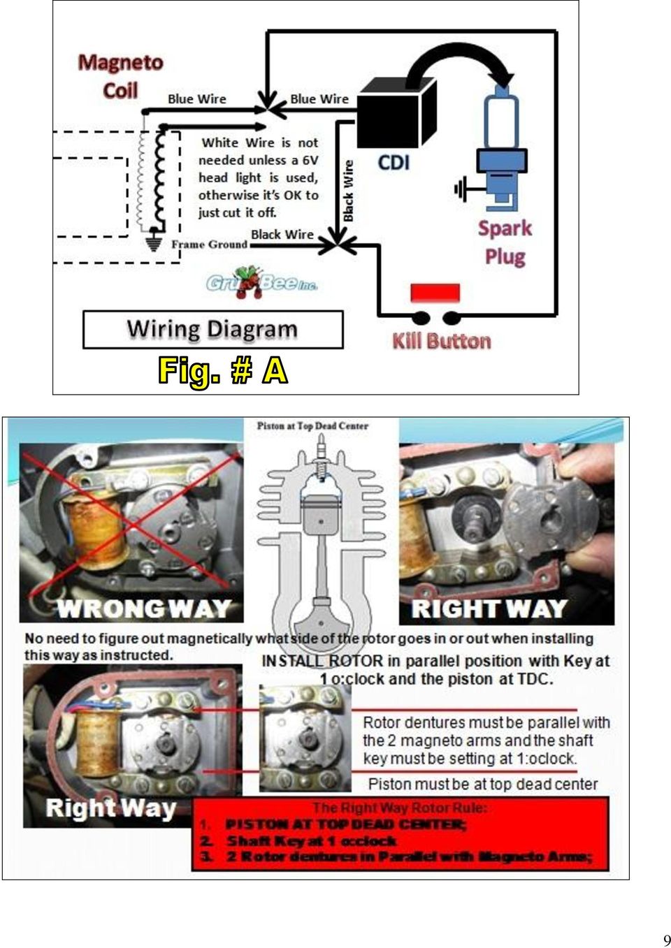
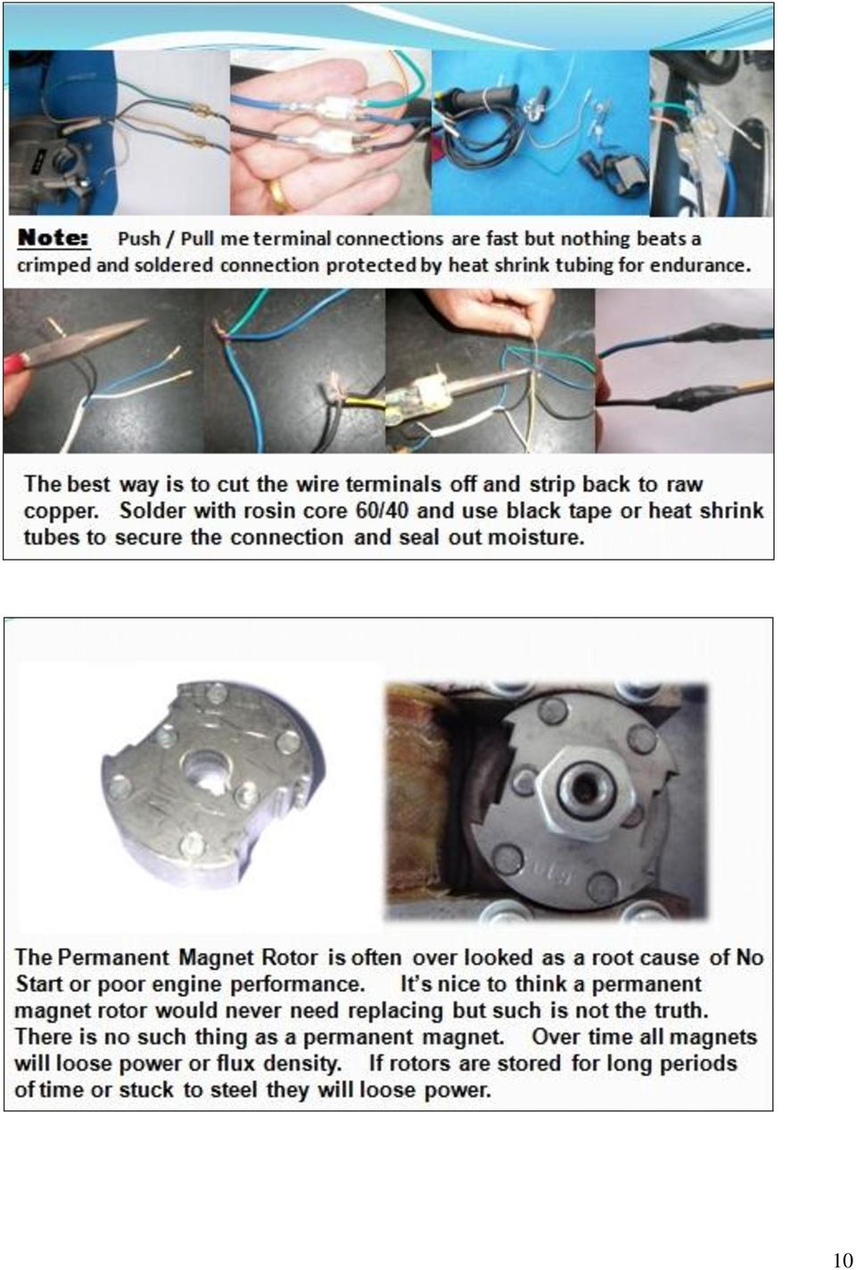
7 Install CDI module on down tube as far away from engine heat as possible. Blk. wire from engine to Blk. of CDI Blue wire from engine to Blue of CDI For CDI Color code is very important: Like to Like. Two kill switch wires can go to either of the remaining 2 empty holes of the CDI terminals: Color code not important. First install Blue & Black wires from engine magneto to same color CDI wires. Warning: Do not hook up backwards or damage will occur to the CDI. Next install the throttle handle kill switch wires into the 2 remaining open holes of the 2 CDI wire terminals. Push the clear rubber protectors over the 2 connections and tape with black electrical tape. The remaining white wire from the engine is not needed unless you want to run a small wattage 6V headlight but it s not recommended as it will rob engine ignition power requirements so is really best to tape this wire up securely or just snip it off at the engine exit plug. Use a heat shrink tube over the wire sheathing to keep water out of the magneto box. NOTE: Even though an extra cost Black PC is an optional engine finish it is not recommended. It only looks good for a while and does nothing for engine performance. It can actually hinder efficient air cooling of aluminum cylinder fins. 7

8 White 330 to 360 ohms Ensure all bullet connectors are soldered on good. New style 4 hole magneto The Magneto is the heart of the ignition system and is activated by rotation of a permanent magnet rotor. When a N/S magnetic flux field rotates past the magneto coil an induced voltage is sent to the CDI via blue / black wires so as to fire the spark plug at the right time. When installing a magneto sand off varnish from back side to ensure a good ground path. Remove varnish here Old style 6 hole magneto Engine firing timing is not adjustable; Position of p/m rotor is fixed to ensure correct timing. If engine does not fire at start up check all bullet connections. Check if kill switch has an unwanted ground. Make sure magneto has a good ground and not insulated by varnish. 8

9 9
10 10
11 SkyHawk Carburetor Family. ( 4 Different kinds) #1. NT Carb. #2. SPEED carb #3. YD CNS Carb #4. YuanDong Skyhawk ( NOTE: Engine Kits to USA have a Fuel Line EPA approved for permeation rating ) 11

12 Procedure for attaching throttle cable to NT & SPEED carburetor slide valve: The small stop on the cable wire end slides through the long groove on the slide valve. Early slide valves were made of brass and later ones are made of black plastic. Beware that there are 2 sizes of black plastic slide valves. Normally; 14.95mm dia. for 66cc and 14.42mm dia. for 48cc are used but slide valve must match the appropriate carb. housing hole dia. to work. Jet sizes are available from 0.80 to 0.65mm. Note: Speed Carburetors have fuel shut off valve and bowl drain petcock; Also these carbs. have larger 14.95mm throttle slides and outlet openings than found in X brand carbs. The square red or the square black AC is interchangeable with small white or black round versions.. Be sure to check carb. air cleaner attach screws for tightness before installing engine: Air cleaner screw coming loose and entering engine is not covered by warranty; A.) Note component positions in pictures; Needle clip is factory set in second slot: If a more rich gas mixture is required you can move the jet pin pac man clip to the next lower position notch.) When the throttle is twisted a spring inside the cylinder valve is compressed and the slide valve is raised to give more air & fuel to the engine. For this to work properly the throttle must twist freely on the handle bar in both directions prior to the cable being installed. B.) Install twist grip throttle on right side of handlebar end. On some handle bars it may be necessary to ream out the handle ID to fit the bar so that the throttle will twist freely. It never hurts to add a few drops of light wt. oil to let trickle down the cable inside the full length of sheathing. C.) After installing cable inside the carburetor you are ready to mount it on engine intake tube and tighten clamp screw. Mount the engine so carburetor sets as level as possible. 12

13 Sealed air adjustment Idle RPM screw #3. YD EPA Carb Skyhawk engines sent to USA in 2010 & 2011 have a CNS YD EPA Carb. that attaches to a long Z intake tube. Be sure the fuel line does not touch the hot engine. Make sure the 2 vent tubes are not left open without plastic lines attached as dirt will enter straight down into the bowl. Only the Small Hole 1.5 wide paper cone air cleaner can be used. The air adjustment screw is sealed per EPA requirements and has external cable choke control. Turning idle screw CW increases RPM. Bowl vent fittings; Install plastic tubes for air; Idle RPM adjustment screw: > set to 1500 rpm Fuel line fitting has a check valve. Idle air adjustment screw: Adjust as required starting with ¼ turn out. EPA carb. is sealed. Bowl overflow and drain line: NOTES: Jet size can vary from 0.78mm to 0.7mm depending if for EPA or for standard aftermarket carbs. Needle pac-man clip is set on #2 position and can be lowered if a richer mixture is required. Avoid tilting carburetor more than 45 degrees as fuel can spill out unless vent tubes are installed vertical. Fuel inlet Idle air adjustmen t Idle rpm adjustment. #4. YuanDong SkyHawk Carb. YuanDong SkyHawk carb. is a redesigned and improved version of the above CNS YD carb and has adjustable air and idle adjustment with vertical fuel inlet. This carb comes with a mm dia. jet. Different Jets from to mm are available from your dealer. White Plastic Rectangle Red Black 4 tube Big Hole paper cone Note; Any of these air cleaners will fit on a #2 and #4 Carbs. 13

14 Choke lever and throttle on handlebar right side Kill Switch Internal parts of #3 & #4 YD &YuanDong Carbs are not the same as old style #1 NT & #2 Speed carbs OFF SET Z CNS Carb Kit: Use this long Z intake tube if bike seat tube has a clearance problem. Install engine so carb. sits level as possible 14

15 Fuel Tank installation A) Attach fuel petcock to tank. Use Teflon tape to seal threads. Careful not to strip threads. B) Mount tank on bike top crossover frame with two supplied brackets and nuts. C) Attach fuel line from tank to carburetor. Best to use USA made fuel line like GoodYear SAE mm obtained from local automotive stores like AutoZone. Factory supplied clear plastic line gets hard over a period of time. *NOTE: Filters are contained in the petcock and in the carburetor inlet. If engine runs poorly clean the valve filter as residue from the tank may have clogged it.. It is highly recommend that a tank liner coating be applied inside the tank before installation. This product known by the names of; KBS, Kreem and Flowliner and is available from most motorcycle dealers; D) Good idea to use a rubber strip to cushion tank on top tube. Gas and Oil Mixture: This engine is a 2 cycle design, therefore, a gasoline/oil mixture is necessary. During the break-in period (1 st gallon of fuel ), the ratio is 16 to 18 parts gasoline to 1 part oil = After break-in, the ratio can be increased to 25 parts gasoline to 1 part oil. Synthetic 2 Stroke Engine Oil can also be used ( Consult your dealer for his personal oil & ratio recommendations for your country and area.)!warning! Remember safety first: Wipe up any spilled fuel. NEVER fuel a hot engine or smoke while fueling. This could result in sudden fire, personal injury. Always move your motorized bike at least 10 feet from any fueling area before attempting to start it. Never leave the tank fuel cap off after fueling as rain water will contaminate the fuel and cause engine failure. MAINTENANCE SECTION # 1. How to Adjust Clutch if signs of slipping or squealing are encountered : A) Disengage clutch by pulling handle bar clutch lever inward and lock into catch lock. B) Remove right side engine clutch cover and remove small locking screw on center *Clutch Adjust Nut. C) Pull clutch arm on left rear engine inward. Back off *Clutch Adjust Nut ¼ turn counterclockwise. D) Release clutch lever and check for slight clutch arm 1/16 free-play on opposite side of engine. Readjust *Clutch Adjust Nut as required to get required 1/6 clutch arm free play. E) Tighten *Clutch Adjust Nut on clutch plate clockwise until just snug. F) Then re-install small locking screw in outer edge of *Clutch Adjust Nut. G) Good idea to place a small gob of grease at gear mesh area. Use grease sparingly! Then replace cover. H) Squirt light grade oil down clutch cable sheathing to reduce friction and make for easy lever pull. 15

16 #2. Carburetor *Clutch Adjust Nut Carbs now sent to the USA per instructions from the Dept. of EPA the idle and air fuel mixture screws must be epoxy sealed or made non adjustable at the factory to avoid end-user tampering. NOTE: Carbs sent to all other countries DO NOT have these air/fuel adjustment restrictions. Depending on your dusty riding conditions, clean air filter every 5 to 20 hours of operation by removing the filter cover to access the screen and element. Wash element with a degreasing agent such as Simple Green or Purple Stuff. Be sure element is completely dry before re-assembly. NOTE: If engine runs poorly clean tank shut off value filter. MAINTENANCE SECTION Continued: #3. 3 pt. Spark Plug Remove spark plug and inspect for excess carbon build up. Clean, re-gap to of an inch if necessary. Check plug after every 20 hours of operation. New spark plugs are available from your selling dealer. Be careful using aftermarket spark plugs as heat range and threads differ greatly. An extra plug is included: When replacing the spark plug in an Angle Fire head it s best to use a 3 point electrode spark plug P/N Z4JC to ensure total combustion. ( Ask your selling dealer for it by part number. ) #4. Exhaust system: After 50 hours of operation check exhaust pipe for excessive oil and carbon build-up. If muffler is clogged your dealer has replecements. Make sure attaching nuts are tight and no exhaust leaks are occurring. Be sure to use supplied support strap to secure exhaust muffler to a solid anchor point on bike frame or engine. A) To remove inside catalytic exhaust insert loosen the retaining screw on end cap and remove. B) Pull cap and baffle out of pipe. Note: Some catalytic inserts are welded in and cannot be removed. If you need a replacement muffler contact your dealer models have an air shield welded on the outside of muffler again per EPA rulings. This insures hot run so catalysis can clean the exhaust. C) Clean with degreaser, rinse and dry. Re-assemble: File muffler attach flange to have smooth flat surface. D) Always use a new exhasut gasket and good idea to use double nuts on muffler attach studs; *NOTE: Excessive periods of low speed operation, idling or leaving fuel petcock in the on position during shut down periods may cause the muffler to become clogged with unburned fuel. #5. Standard Bike 1/2x1/8 Chain is standard. HD 415 is available as an option. Every time bike is ridden check the tension of the drive chain by: A) Rolling to bicycle forward to remove slack from the bottom of the chain. B) Find the center and push downward on the top of chain while measuring the deflection. C) Tighten chain if deflection is more than ½ inch. #6. Head Bolts: Tighten all fasteners after each five hours of operation. Most important to check Cylinder head bolts : Tighten in a X pattern to 10 ft/lb using a torque wrench. A two piece cylinder and 16

17 head design engine requires head bolts be kept tight. Important: Check head bolts before each and every long ride, vibration can cause them to loosen and blow a head gasket. Caution: Do not over torque or head bolts may break off. ( Twisted or broken head bolts due to over tightening is not covered by warranty. ) #7. Right side gears: Remove cover plate and keep small amount of heavy grease on gear train. Do not over grease as leaks will occur and also may adversely affect clutch operation. Regular greasing if required will help reduce gear wear and keep gear train quiet. #8. Left side drive: Routinely pack grease on the clutch 47mm long push rod located at the 10T sprocket and also in cover hole around the lever cam. This will make easy clutch lever operation. ( Make sure the ball bearing D-24 is inserted in the D-20 clutch tube ahead of the D-26 push rod.) Items, tools and extra service parts in tool kit; Typical Engine ID plates: General Information Obey all traffic regulations. Always wear a helmet while riding. Remember that you are riding a motorized bicycle and other traffic may not be able to see you. Never operate your motorized bicycle on a pedestrian through way or sidewalk while the engine is operating. Never operate your motorized bicycle in an unsafe manner. Check local and state laws before riding on streets & wear a helmet. ENGINE STARTING & OPERATION PROCEDURE IMPORTANT: PLEASE READ THIS: Gas and Oil Mixture for Fuel ratio The engine is a 2 cycle design, therefore, a gasoline/oil mixture is necessary. During the break-in period (1 st gallon of fuel), the ratio is 18 parts gasoline to 1 part 2 cycle oil. After the break-in period, the ratio is increased to 25 parts gasoline to 1 part oil. The engine crankshaft bearings are lubricated from the oil in the gas mix. A rich break in mixture ensures bearings will not cease.!warning! Remember safety first: Wipe up any spilled fuel. NEVER fuel a hot engine or light a cigarette while fueling. This could result in sudden fire, personal injury. Always move your motorized bike at least 10 feet from any fueling area before attempting to start it. Never leave the tank fuel cap off after fueling as rain water will contaminate the fuel and cause engine failure. Step #1. After filling tank with the correct oil/gas mix open the tank fuel valve. Fuel line is in the open position when the small lever is pointed down. Move choke lever to the on position. This is the small lever at the end of the choke cable All the way Up the choke is on. All the way Down the choke is off. Move progressively downward to off position during engine warm up period. Engine Starting procedure for Lever Clutch Models: 1. Pull the handlebar clutch lever inward, to disengage the engine from the rear wheel. 2. Pedal; (down hill if possible for first start) 3. A mid frame or rear wheel bike stand is helpful to start the engine in place. 4. Let out the clutch lever all the way out and continuing to pedal. The result is a direct engine hook up via the friction clutch with the rear wheel via chain and sprocket. The engine will now start spinning, Pedal until motor starts. Accelerate slowly at first.. 5. Twist throttle to increase speed, reverse twist throttle to decrease speed. To stop, disengage clutch and apply brakes. To accelerate, pedal and release clutch while opening throttle. 6. Adjust choke to the smoothest engine running position. 17

18 7. After warm up push choke lever all the way down. If engine races too fast, or too slow, pull clutch lever and lock in the notched catch, stop and adjust engine rpm. 8. If the rpm needs adjusting, turn the idle adjust screw found on the right side in or out slowly to obtain the proper idle speed of about 1500 rpm +/- 100 rpm. CW to increase and CCW to decrease rpm. To correctly break the engine in, do not exceed 15 mph or exceed 30 minutes of continual running for first tank of gas. Note: Engine will develop more power after break in. 9. To stop the engine, push Kill switch and turn off gas valve at tank. Turning off the gas will prevent fuel from being siphoned from tank. Warning Note: Never leave the tank gas valve in open position when engine is not running or the bike is in storage. 10. After or before each ride check all mounting fasteners, including hd. Bolts, axle sprocket and brakes. 11. Warning Note: Engine lock up or piston seizure due to improper gas / oil mixture will not be covered by factory warranty. This the responsibility of the owner / operator to make sure the gas and oil is mixed correctly. YuanDong SkyHawk mfg. > WARRANTY POLICY: This is a parts kit: The installer is the prime contractor and accepts all product liability. Proper use and maintenance is required for the continued enjoyment of a motorized bike. This product has been manufactured to strict quality control standards. For kit parts warranty policy contact your selling dealer. Warranty approval is subject to factory inspection and only the defective part or parts will be replaced, not the complete kit or engine. Only the defective part or parts should be returned to the selling dealer for his warranty replacement consideration. Your dealer may require you to obtain his authorization before returning defective parts. Include description and picture of failure with as many details as possible. Note: Seized pistons due to improper gas / oil mix or shipping damage due to carrier neglect is not warranty. Inability to install or adjust components is not warranty. Failure caused by loose fasteners or loose head bolts not being torque regularly is not warranty. Failure to get the engine to run at max power with inferior fuel is not warranty. Failure to adjust carburetor idle setting. Clogged up inline fuel filters is not warranty. Broken bolts and or broken castings due to over-torque of fasteners is not warranty. Broken drive chains is not warranty. Use of nitrous oxide gas for power boost voids warranty. Use of KickAss Bottle boost does not void warranty if used per instructions. Failure to adjust clutch operation is not warranty. Milling the head, or cyl. bottom to increase compression voids warranty. Rust in gas tank is not warranty as all tanks should be KBS, Kreem or Flowliner coated inside before installation. Before calling your dealer about an engine problem review the step by step trouble shooting guide listed here-in on page 27. When replacing the spark plug in an Angle Fire head it s best to use a 3 point electrode spark plug P/N Z4JC to ensure total combustion. 18

19 OPTIONAL COMPONENTS Chrome parts for engine dress up are available from your selling dealer; Long & Short expansion chamber racing exhaust are available; Short expansion chamber may require the wide pedal kit in order to clear pedals. Improved catalytic muffler for 2010 / 2011 USA EPA requirements has twice the size of palladium insert as in 2008 & 09 plus an outside air shield; Two psc. STREET POO POO PIPE available in dealer service parts. 19

20 Wanna Pedal unrestricted? Just pull 2 pins and pedal freely. Wanna Motor? Then just stick em back in. Engine Shift-Kit for multi speed bikes. 20

21 MSK = Multi Shift Kit: Allows using the bike s right side rear wheel multi speed derailer system to work like a transmission for hill climbing or extra speed. However, engine pedal starting is a little more difficult. An optional left side engine recoil rope pull starter is recommended if it will clear your bike pedals. MS kits are available in USA aftermarket from Sick Parts Co. and also from SkyHawk factory with a Brazilian designed version pre-installed on the engine for a 3F labor saving >> form, fit and function benefit. Should you be lucky enough to find a dealer who has one of our GT2 special bikes made for motorizing you can t go wrong. These bikes have thicker frames along with GruBee HD axles with hub mounted sprockets utilizing a 3 brake system and built-in gas tank. Gt2A is made of alum. alloy! 21
22 GT2A frames w/ rubber mt. are now available for WD distribution: 22
23 #4 CNS YuanDong SkyHawk Carb. 23
24 #11 Air Cleaner CNS Carburetor p/n C-32CNS66-EPA 24
25 25
26 C. For Standard NT and SPEED carb. ( Not for #1 or #2 CNS Carbs.) 2.5 liter gas tank plated inside to help reduce rust from occuring 4 36T or 44T or 48T or 56T REAR WHEEL SPROCKET Drive Sprocket 26
27 27
28 The ETHANOL 101 Home Study Course What you need to know about Ethanol fuel when used in small engines; Outdoor power equipment dealers and mechanics are finding themselves dealing with a flood of frustrated owners experiencing engines not running right or having gummed up carburetors only to bring them back a month or so later with the same complaint. What the customer does not realize is that the problem is not the engine! It s the fuel!!!! The introduction of ethanol, otherwise known as alcohol, into the fuel has caused a wide range of problems. While ethanol is regarded as a fuel, blending it with gasoline results in these 4 conditions. Rough idle: Hard starting after leaving the engine sit idle, ( not used ), for several weeks : Gummed up carburetor jet: Loss of power: Ethanol in gasoline breaks down and forms gums very quickly. Ethanol and Gasoline do not chemically bond with each other, instead they are held together in a loose colloidal suspension much like you would see in an oil and vinegar salad dressing mix. The fact is ordinary fuel adjustment additives developed 50 years ago and still on the market today do not correct these 4 ethanol problems. 1. Debris in gasoline caused by Ethanol. Varnish Gums form in the fuel tank and in the carburetor bowl as E5, E10 & E15 ethanol fuel ages. These particles can clog Filters and Needle Jets. Modern day fuel additives break down the enzymes into sub micron sized particles that can be easily burned during the combustion process. 2. Excessive water in the fuel and phase separation. Ethanol attracts moisture from the atmosphere and forms a ethanol and water mix in the gasoline. Ethanol blended fuel will naturally hold 0.5% water in separation, but when water levels exceed this threshold, or when fuel cools significantly, the water/ethanol mix drops out of suspension which is called phase separation. Excessive water in the fuel causes engines to run rough, stall and can lead to internal engine damage. A good fuel additive allows the water to mix with the fuel and get burned off to create a dried out tank result. 3. Ethanol fuel breaks down quickly. As ethanol evaporates the fuel looses octane and becomes what is known as stale. This causes hard starts and engine rattle as well as loss of power and engine damage. A good fuel additive will enhance correction to fuel break down for up to 2 years. 4. Ethanol causes lost power and lost performance. Ethanol added to fuel does not allow as much energy as traditional gasoline. This results in poor engine performance. A good adjustment additive will break apart large clusters of fuel molecules, creating more surface area. This in turn allows additional oxygen to react during combustion which results in complete fuel burning and reduces toxic exhaust emission. The laws of some states in the USA do not require the gas station to tell you how much ethanol is in the gas they sell. E-10 or 10% is supposed to be the legal ethanol limit but up to 50% has been found in some offbrand gasoline. Adding a dry gas additive is not the answer either as these products contain more alcohol which now you know is really Ethanol and will just accelerate the problem into the realm of the third kind. Having said all the bad news here s some good news! There are some additives on the market that will in fact correct the short comings of having Ethanol in gasoline and will allow easy starting even after extended long periods of not running the engine. These additives must contain enzymes that allow more oxygen to bond with the fuel hydrocarbons thus allowing a more complete combustion burn of the fuel charge. This translates into these advantages. Easier Engine Starting: Better throttle response: Decreased exhaust emissions and decreased visible exhaust smoke: Prevention of varnish gum deposits: Increased fuel economy: Helps prevent Phase Separation that can occur in stored fuel when water and ethanol bond together and then falls out resulting in degraded fuel that prevents good engine performance. The best policy is to avoid using any gasoline with Ethanol in it. This 101 article does not recommend any brand of additive for Ethanol correction, however here s a brand claiming to have benefit; StarTron 28
29 GGG-2 48cc & 66cc Dual Start Models Centrifugal clutch operation> Rope Pull & Pedal start: GGG = Give Gas Go NOTE: Dual start GGG-2 model does not use any oil in the clutch housing as did older models made in the past. GGG-2 runs with a standard friction clutch and also has a dry centrifugal clutch. A standard friction clutch engine can be converted to GGG-2 with the conversion kit shown below. Engine can be started by rope pull or by pedal method. Note: Do not add any Oil in crankcase. Complete GGG-2 Bottom engine half is available as a service part.. A one piece or a 3 pcs. wide pedal crank is needed in order for pedals to clear the wider GGG-2 engine. Note: This item is not always included in engine kits. New improved Rope Pull now available with steel cable instead of nylon rope; All metal, no plastic recoil, Ask your supplying dealer; Conv. kit to make a friction clutch engine into GGG-2 mode Engine can then be both pedal and rope pull started. No oil bath required, No not add oil. Centrifugal clutch has over-running mechanism to allow engine pedal starting and can also be rope pull started. Long screw shown above is a tool used to remove clutch from shaft. How to Start: After completing Step #1. for a standard engine pull the recoil rope or engine can be pedal started just like a friction clutch model. Use a wax coating on the pull rope to avoid breaking and ensure long life. Accelerate slowly at first until engine warms up and choke lever is pushed all the way down to off position. Note: End user or installer is the vehicle manufacture. End user assumes all product liability and assumes all compliance to the laws of the land; Quality installation is paramount for safe operation. 29
DR50 Hensim Dirt Runner 49cc Dirt Bike (VIN PREFIX LLCH or LUAH)
") Page 1 of 21 Product Information Baja Web > Product Information > Parts Lists > DIRTBIKE > DR50 Hensim Dirt Runner 49cc Dirt Bike (VIN PREFIX LLCH or LUAH) DR50 Hensim Dirt Runner 49cc Dirt Bike (VIN PREFIX
Page 1 of 21 Product Information Baja Web > Product Information > Parts Lists > DIRTBIKE > DR50 Hensim Dirt Runner 49cc Dirt Bike (VIN PREFIX LLCH or LUAH) DR50 Hensim Dirt Runner 49cc Dirt Bike (VIN PREFIX
1/29/2008 DR50. Baja Motorsports Inc. P.O. Box 61150 Phoenix, AZ 85082 Toll Free: 888-863-2252 PART NUMBERS PRICES ARE SUBJECT TO CHANGE 1 of 45
 DR50 Toll Free: 888-863-2252 PART NUMBERS PRICES ARE SUBJECT TO CHANGE 1 of 45 CYLINDER & CYLINDER HEAD Part UPC Number Description Baja Description 1 DR50-001 842645074424 CYLINDER 1 1 2 DR50-002 842645074431
1/29/2008 DR70. Baja Motorsports Inc. P.O. Box 61150 Phoenix, AZ 85082 Toll Free: 888-863-2252 PART NUMBERS PRICES ARE SUBJECT TO CHANGE 1 of 43
 DR70 Toll Free: 888-863-2252 PART NUMBERS PRICES ARE SUBJECT TO CHANGE 1 of 43 CYLINDER & CYLINDER HEAD 1 DR70-001 883099044472 CYLINDER 1 1 2 DR70-002 883099044489 GASKET, CYLINDER 1 1 3 DR70-003 883099044496
DR90. Baja Motorsports Inc. P.O. Box 61150 Phoenix, AZ 85082 Toll Free: 888-863-2252 PART NUMBERS AND PRICES ARE SUBJECT TO CHANGE 1 of 51
 DR90 Toll Free: 888-863-2252 PART NUMBERS AND PRICES ARE SUBJECT TO CHANGE 1 of 51 CYLINDER & CYLINDER HEAD 1 DR90-001 842645048166 CYLINDER 1 1 2 DR90-002 842645048173 GASKET, CYLINDER 1 1 3 DR90-003
TABLE OF CONTENTS. Section 1 - Assembling your new pit bike.
 Orion Pit Bike Sales Owners Manual (All information and content is the property of Orion Pit Bike Sales. Any attempt to copy or resell is a direct violation of our copyright. All violators will be prosecuted)
1/29/2008 DR125 / DR150. Baja Motorsports Inc. P.O. Box 61150 Phoenix, AZ 85082 Toll Free: 888-863-2252 PARTS AND PRICES ARE SUBJECT TO CHANGE 1 of 55
 DR125 / DR150 Toll Free: 888-863-2252 PARTS AND PRICES ARE SUBJECT TO CHANGE 1 of 55 CYLINDER HEAD ASSY. 1 125-001 883099006937 CYLINDER HEAD COVER 1 1 2 125-002 883099006944 BOLT M6X28 2 3 3 125-003 883099006951
DR125 and DR150 Hensim Dirt Runner 125cc and 150cc Dirt Bike (VIN PREFIX LLCH or LUAH)
") Parts Lists - DR125 and DR150 Hensim Dirt Runner 125cc and 150cc Dirt Bike (VIN PR... Page 1 of 25 Product Information Baja Web > Product Information > Parts Lists > DIRTBIKE > DR125 and DR150 Hensim Dirt
Parts Lists - DR125 and DR150 Hensim Dirt Runner 125cc and 150cc Dirt Bike (VIN PR... Page 1 of 25 Product Information Baja Web > Product Information > Parts Lists > DIRTBIKE > DR125 and DR150 Hensim Dirt
DR90. Baja Motorsports Inc. P.O. Box 61150 Phoenix, AZ 85082 Toll Free: 888-863-2252 PART NUMBERS AND PRICES ARE SUBJECT TO CHANGE 1 of 51
 DR90 Toll Free: 888-863-2252 PART NUMBERS AND PRICES ARE SUBJECT TO CHANGE 1 of 51 CYLINDER & CYLINDER HEAD Part UPC Number Description Baja Description 1 DR90-001 842645048166 CYLINDER 1 1 2 DR90-002
MAINTENANCE OF WHEELMOVE IRRIGATION SYSTEMS
 MAINTENANCE OF WHEELMOVE IRRIGATION SYSTEMS F. Richard Beard, Agricultural Equipment, Structures and Electricity Robert W. Hill, Biological & Irrigation Engineering Boyd Kitchen, Uintah County Extension
BR150 Pmi Baja Reaction 150cc Go Kart (VIN PREFIX L4VM)
") Page 1 of 21 Product Information Baja Web > Product Information > Parts Lists > GOKART > BR150 Pmi Baja Reaction 150cc Go Kart (VIN PREFIX L4VM) BR150 Pmi Baja Reaction 150cc Go Kart (VIN PREFIX L4VM)
Page 1 of 21 Product Information Baja Web > Product Information > Parts Lists > GOKART > BR150 Pmi Baja Reaction 150cc Go Kart (VIN PREFIX L4VM) BR150 Pmi Baja Reaction 150cc Go Kart (VIN PREFIX L4VM)
Volkswagen Jetta, Golf, GTI 1999, 2000 Brake System 46 Brakes - Mechanical Components (Page GR-46)
") 46 Brakes - Mechanical Components (Page GR-46) Front brakes Brake pads, removing and installing Brake pads, removing and installing FN 3 brake caliper, servicing FS III brake caliper, servicing Rear wheel
46 Brakes - Mechanical Components (Page GR-46) Front brakes Brake pads, removing and installing Brake pads, removing and installing FN 3 brake caliper, servicing FS III brake caliper, servicing Rear wheel
TABLE OF CONTENTS. I. TROUBLESHOOTING... 2 - Section 1.01: Common Problems/Solutions... 2
 BAL Accu-Slide System I. Table of Contents TABLE OF CONTENTS I. TROUBLESHOOTING... 2 - Section 1.01: Common Problems/Solutions... 2 II. GETTING STARTED... 5 - Section 2.01: Tools You Will Need... 5 - Section
13. REAR WHEEL/BRAKE/SUSPENSION
 13. REAR WHEEL/BRAKE/SUSPENSION 13 3.5~4.5kg-m 8.0~10.0kg-m 0.8~1.2kg-m 3.0~4.0kg-m 2.4~3.0kg-m 3.5~4.5kg-m 6.0~8.0kg-m 13-0 13. REAR WHEEL/BRAKE/SUSPENSION 13 REAR WHEEL/BRAKE/SUSPENSION SERVICE INFORMATION...
 1 What's included: Box A Box B 1 x Box of 80cc Class (66cc True Displacement) ZB-JET80-SR Complete Top End Assembly 1 x Push Clutch Lever 1 x Heavy Duty 415 Chain 1 x Chain Guard 1 x Throttle Cable (Adjustable)
STEERING SYSTEM - POWER
 STEERING SYSTEM - POWER 1990 Nissan 240SX 1990 STEERING Nissan - Power Rack & Pinion Axxess, Maxima, Pulsar NX, Sentra, Stanza, 240SX, 300ZX DESCRIPTION The power steering system consists of a rack and
cbperformance.com Please read this entire brochure prior to installing your CB Performance Products MAGNASPARK II distributor.
 - Easy -wire installation with no external spark box necessary, but can be used with one. - Precision CNC machining and hand assembled construction. This is a premium product. - Accurate super hot spark
Front brakes (FN- 3), servicing
, servicing") j a t Front brakes (FN- 3), servicing 46-1 Front brakes, servicing Note: Install complete repair kit. After replacing brake pads and before moving vehicle, depress brake pedal several times firmly to properly
j a t Front brakes (FN- 3), servicing 46-1 Front brakes, servicing Note: Install complete repair kit. After replacing brake pads and before moving vehicle, depress brake pedal several times firmly to properly
Owner s Manual Read and keep this manual. Patents World Wide
 Owner s Manual Read and keep this manual. Patents World Wide S & S Industries, Inc., Sarasota, FL, USA www.trail-gator.com Copyright 2008 All Rights Reserved The following manual is provided to assist
ASSEMBLY DIAGRAM AND ASSEMBLY REFERENCE ULTIMA OLD SCHOOL 2 EVO & TC BELT DRIVE UNITS
 ASSEMBLY DIAGRAM AND ASSEMBLY REFERENCE ULTIMA OLD SCHOOL 2 EVO & TC BELT DRIVE UNITS BELT DRIVE ASSEMBLIES Part# 58-850 2 Old School Belt Drive Assembly - Polished Part# 58-851 2 Old School Belt Drive
DETACHABLE WINDSHIELD AND DOCKING HARDWARE KIT
 -J00 REV. 00-- DETACHABLE WINDSHIELD AND DOCKING HARDWARE KIT GENERAL Kit Number -A, 0-, -, 0-, -, - 0, -0 Models These kits fit and later FXST, FXSTB, FXSTC, and and later FXDWG Harley-Davidson model
Overview PARTS LIST. B. Lever mounting base C. Flush handle assembly D. Grey/Blue float stop E. Grey float (Full Flush) F. Flush valve washer
 F. Flush valve washer") Overview READ ENTIRE INSTRUCTIONS BEFORE STARTING INSTALLATION PARTS LIST A. Flush valve B. Lever mounting base C. Flush handle assembly D. Grey/Blue float stop E. Grey float (Full Flush) F. Flush valve
Overview READ ENTIRE INSTRUCTIONS BEFORE STARTING INSTALLATION PARTS LIST A. Flush valve B. Lever mounting base C. Flush handle assembly D. Grey/Blue float stop E. Grey float (Full Flush) F. Flush valve
DYNA RIDER FOOTBOARD KIT
 -J0 REV. 0-0-0 DYNA RIDER FOOTBOARD KIT GENERAL Kit Number 000 Models For model fitment information, see the P&A Retail Catalog or the Parts and Accessories section of www.harley-davidson.com (English
INSTALLATION INSTRUCTIONS. 6111 Air Spring Kit 2011+ Ford F250/F-350 Single Wheel 2WD 2011+ Ford F350 Dually 2WD IMPORTANT NOTES
 INSTALLATION INSTRUCTIONS 6111 Air Spring Kit 2011+ Ford F250/F-350 Single Wheel 2WD 2011+ Ford F350 Dually 2WD Thank you for purchasing a quality Hellwig Product. PLEASE READ THIS INSTRUCTION SHEET COMPLETELY
Slide the new steering column shaft through the steering column from the driver compartment.
 Slide the new steering column shaft through the steering column from the driver compartment. Push the column shaft through the steering column until the machined end is out past the column lower bushing.
SELF-STEERING AXLE TABLE OF CONTENTS
 SELF-STEERING AXLE TABLE OF CONTENTS Section 1 - Introduction Section 2 - Pre-Installation Check List Section 3 - Ride Height Adjustments Section 4 - Suspension Mount Section 5 - Axle Mount Section 6 -
BSA Goldstar Parts - Price List April 2016. 65-1137 Exhaust Lifter Cable 15.00. 65-1163 Exhaust Lifter Cable Holder S/S 9.00
 Rocker Boxes 65-1137 Exhaust Lifter Cable 15.00 65-1163 Exhaust Lifter Cable Holder S/S 9.00 2-443 Exhaust Lifter Cable Holder Nut S/S 0.50 65-401 Exhaust Lifter Spindle Felt 2.00 65-387 Exhaust Lifter
Volkswagen Jetta, Golf, GTI 1999, 2000 Brake System 47 Brakes - Hydraulic Components (Page GR-47)
") 47 Brakes - Hydraulic Components (Page GR-47) FS III front brake calipers, servicing Front brake caliper piston, removing and installing FN 3 front brake calipers, servicing Front caliper piston, removing
47 Brakes - Hydraulic Components (Page GR-47) FS III front brake calipers, servicing Front brake caliper piston, removing and installing FN 3 front brake calipers, servicing Front caliper piston, removing
Rating when used as a weight carrying hitch without spring bars:
 BOLT-TOGETHER WEIGHT DISTRIBUTING HITCH SYSTEM Rating when used as a weight distributing hitch with spring bars: Part Number 48051 4805 48053 48054 Max Tongue Weight 550 Ibs. 750 Ibs. 1000 Ibs. 1400 lbs.
SLACK PERFORMANCE KARTS
 SLACK PERFORMANCE KARTS SET UP GUIDE Thank you for purchasing a 2013 Slack Axiom Chassis. Performance Mfg. strives to provide you with the very best chassis and components on the market today. Your satisfaction
2006 HEADSHOK Service Video #1
 LEFTY SPEED DLR DAMPING CARTRIDGE This document explains how to properly remove, disassemble, inspect, reassemble and reinstall the Lefty Speed DLR2 damping cartridge. It is a document to be used in conjunction
Rebuild Instructions for 70001 and 70010 Transmission
 Rebuild Instructions for 70001 and 70010 Transmission Brinn, Incorporated 1615 Tech Drive Bay City, MI 48706 Telephone 989.686.8920 Fax 989.686.6520 www.brinninc.com Notice Read all instructions before
AKRAPOVIC SLIP-ON EXHAUST SYSTEM for the HONDA CB1000R
 Installation instructions: *502131* AKRAPOVIC SLIP-ON EXHAUST SYSTEM for the HONDA CB1000R Congratulations on purchasing an Akrapovic exhaust system. Please read these installation instructions carefully.
TUTORIAL. REbUILdING. REAR CALIpER O-RING CONVERSION CORVETTE 1965-82. Part #: HT-2
 Part #: HT-2 1965-82 CORVETTE O-RING CONVERSION REAR CALIpER REbUILdING TUTORIAL Choosing a Brake Caliper Rebuild Kit Standard Lip Seals vs. O-Ring Seals Lip seal design seals are used on 1965-1982 Corvette
Not required for most applications Not required for most applications High pressure (12-803 provided) High pressure (12-803 provided)
 High pressure (12-803 provided)") ELECTRIC FUEL PUMPS P/N 12-801-1, 712-801-1, 12-802-1, 712-802-1, 12-815-1, & 712-815-1 FUEL PRESSURE REGULATORS P/N 12-803, 12-501, 12-804, 12-500, & 15812NOS Installation Instructions THESE INSTRUCTIONS
ELECTRIC FUEL PUMPS P/N 12-801-1, 712-801-1, 12-802-1, 712-802-1, 12-815-1, & 712-815-1 FUEL PRESSURE REGULATORS P/N 12-803, 12-501, 12-804, 12-500, & 15812NOS Installation Instructions THESE INSTRUCTIONS
HYDRAULIC LIFT TABLE CART 2200-LB.
 HYDRAULIC LIFT TABLE CART 2200-LB. OWNER S MANUAL WARNING: Read carefully and understand all MACHINE ADJUSTMENT AND OPERATION INSTRUCTIONS before operating. Failure to follow the safety rules and other
DANA 30 MANUAL HUB CONVERSION KIT
 DANA 30 MANUAL HUB CONVERSION KIT 12194 PLEASE READ AND UNDERSTAND ALL INSTRUCTIONS BEFORE YOU BEGIN Your safety and the safety of other motorists is very important. Your Jeep is an off road capable vehicle
DiscPlus DX195 and DX225 Air Disc Brakes
 Revised 11-04 Technical Bulletin Revised 1 Technical 11-04 Bulletin DiscPlus DX195 and DX225 Air Disc Brakes Inspection, Installation and Diagnostics Air Disc Brake Inspection Intervals and Procedures
INDEX INTRODUCTION. Reference No. 10-21L-01 R E V I S E D : 2 0 0 5 0 2
 10-21L-01 SRM-2305, SRM-2305SI 1 1 INTRODUCTION We are constantly working on technical improvement of our products. For this reason, technical data, equipment and design are subject to change without notice.
TRANS-05, Torque Tube Removal, Rebuilding, and Installation
 TRANS-05, Torque Tube Removal, Rebuilding, and Installation Tools Metric Wrench Set Metric Socket Set Jack Stands (6 minimum) Floor Jack 8mm Cheesehead socket (also referred to as 12 point internal socket
GEET Fuel Processor Plans
 GEET Fuel Processor Plans This is a greatly simplified Proof of Concept version of the GEET Fuel Processor that just about anyone can build from parts from a local Hardware store in a weekend for very
INSTALLATION INSTRUCTIONS. 6108 Air Spring Kit 2011+ Ford F250 Single Wheel 4WD 2011+ Ford F350 Dually 4WD (2011 F350 Single Wheel 4WD use p/n 6113)
") INSTALLATION INSTRUCTIONS 6108 Air Spring Kit 2011+ Ford F250 Single Wheel 4WD 2011+ Ford F350 Dually 4WD (2011 F350 Single Wheel 4WD use p/n 6113) Thank you for purchasing a quality Hellwig Product. PLEASE
INSTALLATION INSTRUCTIONS 6108 Air Spring Kit 2011+ Ford F250 Single Wheel 4WD 2011+ Ford F350 Dually 4WD (2011 F350 Single Wheel 4WD use p/n 6113) Thank you for purchasing a quality Hellwig Product. PLEASE
BOWIE PUMPS OPERATION - MAINTENANCE
 BOWIE PUMPS OPERATION - MAINTENANCE PUMPING PRINCIPLE: The meshing owieeof the gears cause a slight depression, with the resulting enmeshing of the gears causing a vacuum drawing the fluid being pumped
11-600036D PRO MAC 60 07/72 to 12/76 IPL 89321 Page 1 of 19 Accessories
 11-600036D PRO MAC 60 07/72 to 12/76 IPL 89321 Page 1 of 19 Accessories 11-600036D PRO MAC 60 07/72 to 12/76 IPL 89321 Page 2 of 19 Accessories 84453 Kit - Piston tool 69191 Kit - Pressure test adaptor
SLP 1.85 Ratio Offset Rocker Arms with Valve Springs, LS3
 PART #50190 SLP 1.85 Ratio Offset Rocker Arms with Valve Springs, LS3 PACKING LIST Before installation, use this check list to make sure all necessary parts have been included. ITEM QTY CHECK PART NUMBER
TUTORIAL. REbUILdING. front CALIpER O-RING CONVERSION CORVETTE 1965-82. Part #: HT-1
 Part #: HT-1 1965-82 CORVETTE O-RING CONVERSION front CALIpER REbUILdING TUTORIAL Choosing a Brake Caliper Rebuild Kit Standard Lip Seals vs. O-Ring Seals Lip seal design seals are used on 1965-1982 Corvette
PARTS MANUAL EH12-2 ENGINE. Model. PUB-EP5713 Rev. 7/99
 PARTS MANUAL Model EH12-2 ENGINE PUB-EP5713 Rev. 7/99 940 Lively Blvd. Wood Dale, IL 60191 Phone: 630-350-8200 Fax: 630-350-8212 e-mail: [email protected] www.robinamerica.com Copyright 1999 Robin
Oregon Fuel Injection
 Corporate Office: P.O. Box 21121, VE Pump Removal and Installation Cummins Lock Timed Applications Removal Clean the exterior of the injection pump and mounting surfaces. 1. Disconnect the fuel return
16 April 2012 1032011-F 1994-2002 Dodge Adjustable Track bar with Relocation Bracket 1
 16 April 2012 1032011-F 1994-2002 Dodge Adjustable Track bar with Relocation Bracket 1 BD Adjustable Track Bar w/bracket Dodge 2500-3500 4WD Models 1994-2002 Dodge 1500 4WD Model 1994-2001 P/N# 1032011-F
SCREAMIN' EAGLE "HEAVY BREATHER" PERFORMANCE AIR CLEANER KIT
 REV. 05-04- SCREAMIN' EAGLE "HEAVY BREATHER" PERFORMANCE AIR CLEANER KIT GENERAL Kit Numbers 95-08B, 9006-09B, 876-0A Models For model fitment information, see the P&A Retail Catalog or the Parts and Accessories
Installation Guide 2010 BMW S1000RR Full Exhaust System
 Installation Guide 2010 BMW S1000RR Full Exhaust System!! THIS PRODUCT IS DESIGNED FOR USE IN CLOSED COURSE RACING AND IS NOT INTENDED FOR HIGHWAY USE!! Congratulations on the purchase of your new TaylorMade
CHROME FRONT BRAKE MASTER CYLINDER KIT
 -J075 REV. 009-0-0 CHROME FRONT BRAKE MASTER CYLINDER KIT GENERAL Kit Number 5-99D, 5-99D Models These Chrome Master Cylinder Kits are designed to replace the original equipment front brake master cylinder
Technical Specifications
 Mfg: Honda Make: XR50R Year: All Product: 81.2cc E-Stage Bore Up Kit (part # 010-1-05-522) 88cc S-Stage Bore Up Kit (part # 010-1-05-502) IMPORTANT - PLEASE READ CAREFULLY We recommend that this performance
FRONT TURN SIGNAL RELOCATION KIT
 -J0 REV. 00-0-0 FRONT TURN SIGNAL RELOCATION KIT GENERAL Kit Number -0 Models This kit fits 00 and later Dyna model motorcycles (except FXDSE), relocating the front turn signal from the handlebars to the
BACKPACK SPRAYERS. MODEL NOS: KSP16 & KSP20 Part Nos: 3402270 & 3402275 OPERATING & MAINTENANCE INSTRUCTIONS GC04/12
 BACKPACK SPRAYERS MODEL NOS: KSP16 & KSP20 Part Nos: 3402270 & 3402275 OPERATING & MAINTENANCE INSTRUCTIONS GC04/12 INTRODUCTION Thank you for purchasing this CLARKE Sprayer, designed for use only with
SCREAMIN' EAGLE "HEAVY BREATHER" PERFORMANCE AIR CLEANER KIT
 REV. 2015-04-23 SCREAMIN' EAGLE "HEAVY BREATHER" PERFORMANCE AIR CLEANER KIT GENERAL Kit Numbers 29299-08, 29098-09 Models For model fitment information, see the P&A Retail Catalog or the Parts and Accessories
Rear wheel brakes, servicing. Стр. 1 из 45. Note:
 Volkswagen Touareg - Rear wheel brakes, servicing Стр. 1 из 45 46-2 Rear wheel brakes, servicing Rear brakes, FN 44 brake caliper, servicing Note: After replacing brake pads, depress brake pedal firmly
1. Lay out 2 pieces of 7/8" tubing and mark for bending as shown. Remember that the bend is in the shaded area as shown below in Figure 1.
 MINI BIKE PLANS Page 1 INTRODUCTION Before starting to build your Mini-Bike, be sure that you have all the parts shown on the material list. You will note that tubing has been used in the construction.
Important: Please read these instructions carefully and completely before starting the installation. TITAN Fuel Tanks
 TITAN pt. no.: 03 0000 0120 Important: Please read these instructions carefully and completely before starting the installation. TITAN Fuel Tanks INSTALLATION INSTRUCTIONS G e n e r a t i o n V Extended
INSPECTION BEFORE RIDING
 INSPECTION BEFORE RIDING Check the following items before riding. ITEM Engine cum transmission oil Fuel Tyres Battery Speedometer Lighting Steering Throttle Clutch Brakes Wheels WHAT TO CHECK FOR Availability
P7100 PUMP INSTALLATION INSTRUCTIONS Diesel Care & Performance Inc
 P7100 PUMP INSTALLATION INSTRUCTIONS Diesel Care & Performance Inc Installation Timing Pin Location CAUTION: Before installing the injection pump, be sure that number 1 cylinder is at the Top Dead Center
Range Road RR Series Semi-Automatic Firewood Processor. Crated Unit Assembly Manual
 Range Road RR Series Semi-Automatic Firewood Processor Crated Unit Assembly Manual 1 1) Undo 8-18mm x 19mm Nuts and bolts, 2 on each leg of top frame 2) Lift top of Metal crate off and move out of work
Volkswagen B3 Passat Manual Transmission 02A 34 Manual Transmission - Controls, Assembly (Page GR-34) 02A 5-speed. Gearshift cable/lever installing
 02A 5-speed. Gearshift cable/lever installing") 34 Manual Transmission - Controls, Assembly (Page GR-34) 02A 5-speed Gearshift cable/lever installing Gearshift housing repairing Gearshift lever repairing lever/relay lever, installing Gearshift mechanism
34 Manual Transmission - Controls, Assembly (Page GR-34) 02A 5-speed Gearshift cable/lever installing Gearshift housing repairing Gearshift lever repairing lever/relay lever, installing Gearshift mechanism
http://waterheatertimer.org/troubleshoot-rheem-tankless-water-heater.html
 http://waterheatertimer.org/troubleshoot-rheem-tankless-water-heater.html TECHNICAL SERVICE DEPARTMENT Removal, Cleaning, & Reinstallation of the Burner Assembly For models 74 & GT199 Required tools -
RULE # 1 is DON T mess with things that you don t know anything about! (Take them to a pro & pay them to fix it)
") OK there seems to be a LOT of problems noted on KatRiders having to do with CARBS, so I thought I d write out sort of a checklist of things to help folks. RULE # 1 is DON T mess with things that you don
OK there seems to be a LOT of problems noted on KatRiders having to do with CARBS, so I thought I d write out sort of a checklist of things to help folks. RULE # 1 is DON T mess with things that you don
360 Automatic Chain Saw UT-10468 Page 1 of 15 Carburetor
 360 Automatic Chain Saw UT-10468 Page 1 of 15 Carburetor 360 Automatic Chain Saw UT-10468 Page 2 of 15 Carburetor 1 93205A 1 Repair Kit 2 93205A 1 Repair Kit 3 93205A 1 Repair Kit 4 93205A 1 Repair Kit
M113 VEHICLE FAMILY RUBBER TRACK INSTALLATION INSTRUCTIONS SOUCY TRACK SYSTEM 04-M113-1ENS (SPLIT IDLER) Litho d in Canada 1 04-M113-1ENS
 Litho d in Canada 1 04-M113-1ENS") M113 VEHICLE FAMILY RUBBER TRACK INSTALLATION INSTRUCTIONS (SPLIT IDLER) 1 # TABLE OF CONTENTS List of parts and tools................................................3 Installation of complete kit...................................................5
M113 VEHICLE FAMILY RUBBER TRACK INSTALLATION INSTRUCTIONS (SPLIT IDLER) 1 # TABLE OF CONTENTS List of parts and tools................................................3 Installation of complete kit...................................................5
K&T Saw Shop 606-678-9623 or 606-561-4983
 13-600072-06 PRO MAC 8200 05/92 to Current IPL 215710-02 Page 1 of 20 Carburetor Assembly www.ktoutdoor.com 13-600072-06 PRO MAC 8200 05/92 to Current IPL 215710-02 Page 2 of 20 Carburetor Assembly 214763-02
Volkswagen New Beetle 2.0 Liter 4-cyl General, Engine (Engine Code AEG) 17 Engine-Lubrication system (Page GR-17)
 17 Engine-Lubrication system (Page GR-17)") 17 Engine-Lubrication system (Page GR-17) Lubrication system components, removing and installing Oil pan, removing and installing Oil pressure and oil pressure switch, checking Dynamic oil pressure warning
17 Engine-Lubrication system (Page GR-17) Lubrication system components, removing and installing Oil pan, removing and installing Oil pressure and oil pressure switch, checking Dynamic oil pressure warning
Owners & Installation Manual for the Sheridan, Mountainair, Pine Valley and Old Forge Ceiling Fan Family
 Owners & Installation Manual for the Sheridan, Mountainair, Pine Valley and Old Forge Ceiling Fan Family Part of the Kiva Lighting Family Custom Lighting and Fans Since 1992 1312 12th St NW Albuquerque,
CONGRATULATIONS! TABLE OF CONTENTS. 1 Safety Warnings 2 About Your Wheels 3 Setting Up Your Wheels 7 Care and Cleaning 8 Warranty
 WHEEL MANUAL CONGRATULATIONS! Congratulations on your purchase of Oval Concepts Wheels. Developed to perform at a high level, it is important that you follow the operation and maintenance instructions
INSTRUCTIONS. FLHR/C/S (Road King) FRONT END LOWERING KIT 1WARNING -J03242 REV. 10-19-04. General. Removal (Left and Right Forks) Kit Number 54614-05
 FRONT END LOWERING KIT 1WARNING -J03242 REV. 10-19-04. General. Removal (Left and Right Forks) Kit Number 54614-05") INSTRUCTIONS -J04 REV. 0-9-04 General FLHR/C/S (Road King) FRONT END LOWERING KIT This kit is designed for installation on 00 and later FLHR/C/S Model Motorcycles. Road King models use the conventional
INSTRUCTIONS -J04 REV. 0-9-04 General FLHR/C/S (Road King) FRONT END LOWERING KIT This kit is designed for installation on 00 and later FLHR/C/S Model Motorcycles. Road King models use the conventional
BILLET HEADLAMP WITH SHORT/TALL MOUNTS
 -J099 REV. 00-0- BILLET HEADLAMP WITH SHORT/TALL MOUNTS GENERAL Kit Number 9-0, 9-0 Models Kit 9-0 is a -/ inch headlamp and kit 9-0 is a -/ inch headlamp. Both kits will fit the models listed in Table.
Contents. Description Page Description Page
 Contents Description Page Description Page Auger Housing Assembly 1 Muffler 18 Handle and Control Assembly 3 Fuel Tank r Assembly 19 Engine and Drive Assembly 5 Clutch Retarder 20 Cylinder Head 7 Retarder
This is the civilian transfer case with the cooling loop only found in the driven gear half of the front case.
 INTRODUCTION The Transfer case used in the AMG Hummer is a New Venture Gear, model 242. This case has been in use for the H-1/Hummer since the early 1990 s. There have been modifications to the internal
Drive shaft, servicing
 Volkswagen Passat B6 - Drive shaft, servicing Стр. 1 из 41 40-7 Drive shaft, servicing Drive shafts, overview I - Assembly overview: Drive axle with CV joint VL100 40-7, Drive axle with CV joint VL100,
ADDING AN ELECTRIC AUXILIARY FAN TO RADIATOR STACK ON 03 ALPINE COACH
 ADDING AN ELECTRIC AUXILIARY FAN TO RADIATOR STACK ON 03 ALPINE COACH The original design of the 03 Alpine Coaches (and perhaps other years as well) did not include any kind of engine fan engage mechanism
COMBINATION SLAB & TRIM SAW INSTRUCTIONS 12, 14, & 16 MODELS
 COMBINATION SLAB & TRIM SAW INSTRUCTIONS 12, 14, & 16 MODELS DESCRIPTION Covington s Combination Trim & Slab Saws are similar in design with different blade and pulley sizes. Sawing operations remain the
Installation Instructions 4508 4508S
 SYMPHONY Spread Lavatory Faucet with Speed Connect Drain Congratulations on purchasing your American Standard faucet with Speed Connect drain, a feature found only on American Standard faucets. Speed Connect
FOR ANY QUESTIONS, PLEASE CALL US @ 727.347.9915 M-F 8:00a.m.-8:00p.m. EST. REAR BRAKES 1 AEROSPACE COMPONENTS 727.347.9915
 REAR BRAKES 1 AEROSPACE COMPONENTS 727.347.9915 REAR BRAKES Before getting started, remove all stock braking components. Pre-assembly of parts: Clean the bolts and the threads in the hat with acetone.
OWNER S MANUAL Table Tennis Table Patent Pending
 OWNER S MANUAL Table Tennis Table Patent Pending Be sure to write your model number and serial number here for future reference. You can find these numbers printed on the bottom of the table. MODEL # T8179
FJ2. 2 Ton Trolley Floor Jack Assembly & Operating Instructions
 FJ2 2 Ton Trolley Floor Jack Assembly & Operating Instructions READ ALL INSTRUCTIONS AND WARNINGS BEFORE USING THIS PRODUCT. This manual provides important information on proper operation & maintenance.
EME 35 Gasoline Engine User Manual
 EME 35 Gasoline Engine User Manual Eagle Master Engine EME 35 User Manual 1 SAFETY INSTRUCTIONS Thank you for purchasing EME 35 gasoline Engine. We at EME always strive to product reliable engines that
ELECTRIC BICYCLE USER MANUAL
 ELECTRIC BICYCLE USER MANUAL 1 Main Technical Parameters and Specification Weight: 23 kg Wheel size: 20 Maximum speed: 25 km/h E BIKE URBAN Range: Up to 45km (with pedal assist) Type: lithium Voltage:
2003 ACCORD - Automatic Transmission Removal
 2003 ACCORD - Automatic Transmission Removal Special Tools Required Engine support hanger, A and Reds AAR-T-12566 Engine hanger balancer bar VSB02C000019 Front subframe adapter VSB02C000016 These special
Tool And Material Checklist
 HOW - TO CV JOINTS CV JOINTS Tool And Material Checklist Screwdriver Metal Shears Breaker Bar or Torque Wrench Assorted Wrenches Wire Evaporating Spray Solvent Pusher Tool Vise Snap Ring or Duckbill Pliers
TITAN Fuel Tanks. INSTALLATION INSTRUCTIONS G e n e r a t i o n V
 TITAN pt. no.: 02 0000 0143 Important: Please read these instructions carefully and completely before starting the installation. TITAN Fuel Tanks INSTALLATION INSTRUCTIONS G e n e r a t i o n V Extended
Before installation it is important to know what parts you have and what the capabilities of these parts are.
 INSTALLATION GUIDE Before installation it is important to know what parts you have and what the capabilities of these parts are. The Recon XZT is the smallest and most powerful gauge of its kind. With
Turbocharger system components, servicing
 21-1 Turbocharger system components, servicing Engine codes: AAZ, 1Z, AHU Observe rules of cleanliness Page 21-10 Turbocharger hoses and lines, connecting Page 21-11 WARNING! Do not re-use any fasteners
DO NOT attempt to repair hub and wheel bearing assembly.
 Page 1 of 6 HUB & WHEEL BEARINGS (WITH PULSE VACUUM HUBLOCK) DO NOT attempt to repair hub and wheel bearing assembly. Removal DO NOT remove hub lock assembly by prying on hub lock legs. This can crack
INSTALLATION GUIDE. Your guide to Stromberg 97 carburetor installation and adjustment
 INSTALLATION GUIDE If you need further information or assistance, please contact your Genuine Stromberg dealer, or email us direct at [email protected] or log on to our Tech Center at www.stromberg-97.com
TECHNICAL BULLETIN. Meritor WABCO Cab Leveling Valves and Chassis Leveling Valves. How the Cab Leveling and Chassis Leveling Valves Work
 Revised 02-00 TECHNICAL BULLETIN Meritor WABCO Cab Leveling Valves and Chassis Leveling Valves This technical bulletin covers both cab and chassis leveling valves manufactured by Meritor WABCO. While the
AXLE SHAFTS - FRONT. 1998 Pontiac Bonneville MODEL IDENTIFICATION DESCRIPTION & OPERATION TROUBLE SHOOTING REMOVAL & INSTALLATION
 AXLE SHAFTS - FRONT 1998 Pontiac Bonneville 1998-99 DRIVE AXLES FWD Axle Shafts - Cars - "C", "G" & "H" Bodies GM Aurora, Bonneville, Eighty Eight, LeSabre, LSS, Park Avenue, Regency, Riviera MODEL IDENTIFICATION
INSTALLATION INSTRUCTIONS FOR 2006-2009 VW MK5
 CI100018 INSTALLATION INSTRUCTIONS FOR 2006-2009 VW MK5 Rabbit, Jetta 2.5L These instructions are applicable to vehicles equipped with either manual or automatic transmissions Thank you for choosing to
Unit: mm(in) Item Standard value Service limit Axle shaft run out - 0.2(0.008)
 Item Standard value Service limit Axle shaft run out - 0.2(0.008)") Rear Wheel/Brake/Suspension 13. Rear Wheel/Brake/Suspension Service Information 13-1 Troubleshooting 13-2 Rear Wheel 13-3 Rear Cushion 13-4 Rear Swing Arm 13-7 Service Information General Safety If the
Rear Wheel/Brake/Suspension 13. Rear Wheel/Brake/Suspension Service Information 13-1 Troubleshooting 13-2 Rear Wheel 13-3 Rear Cushion 13-4 Rear Swing Arm 13-7 Service Information General Safety If the
Char-Lynn Spool Valve Hydraulic Motors. Repair Information. W Series Geroler Motors
 Char-Lynn Spool Valve Hydraulic Motors Repair Information W Series Geroler Motors with Parking Brake 004 Nut Key Ring, Retaining Bearing Ring, Retaining Ring, Retaining Washer (Thick), Pressure Washer,
XL PREMIUM OIL COOLER KIT
 -J05 REV. 0-0-0 XL PREMIUM OIL COOLER KIT GENERAL Kit Number 0008 Models For model fitment information, see the P&A Retail Catalog or the Parts and Accessories section of www.harley-davidson.com (English
Elo Touch Solutions Wall-mounting Kit for the 5501L IDS Touchmonitors
 Installation Manual Elo Touch Solutions Wall-mounting Kit for the 5501L IDS Touchmonitors SW602206 Rev B Table of Contents Chapter 1: Safety Warning... 3 Chapter 2: Kit Contents... 4 Included in Kit...
Front axle components, overview
 just a test. Front axle components, overview 40-1 General Information Load bearing components and parts of the suspension must not be welded or straightened. Vehicles without drive axle must not be moved,
MEASURING WHEEL ALIGNMENT
 MEASURING WHEEL ALIGNMENT 2003-04 WHEEL ALIGNMENT Specifications & Procedures - Hummer - H2 Steering and vibration complaints are not always the result of improper alignment. One possible cause is wheel
Assembly and Usage Instructions
 Assembly and Usage Instructions A Product 5885 West Van Horn Tavern Road Columbia, MO 65203 www.caldwellshooting.com Instruction #1001667 Limited Warranty Every Caldwell product is warrantied to be free