Leica INM100 Optical Microscope Operation Manual
|
|
|
- Irma Allison
- 9 years ago
- Views:
Transcription
1 Leica INM100 Optical Microscope Operation Manual Roger Robbins May 17, 2006 The University of Texas at Dallas Erik Jonsson School of Engineering DOCUMENT NUMBER: SU2006-LI-001 Page 1 of 28

2 Leica INM100 Optical Microscope Operation Manual Roger Robbins 5/17/2006 C:MyDocuments\CleanRoomGeneral/Equipment/OoticalMicroscopes/INM100/INM100Manual.doc Table of Contents Table of Contents... 2 Leica INM100 Optical Microscope Operation Manual... 4 Purpose... 4 Introduction... 4 Microscope Description... 4 General Microscope Operation... 6 Startup... 6 Stage Positioning... 6 Objective Lens Selection... 6 Lighting... 7 Lamp Power... 7 Filter Selection... 8 Viewing... 8 Focus... 9 Bright Field Imaging... 9 Dark Field Imaging Condenser Aperture Contrast Control Interference Contrast Imaging Special Microscope Operation Fluorescence Imaging Extra Magnification Image Capture Software Basic Image Capture Procedure Conclusion Appendix A* Servicing and Maintenance The Most Frequent Faults in Microscopy Uneven Illumination Flat Images Un-sharp Patches in the Microscopic Image Unnatural Contrast DOCUMENT NUMBER: SU2006-LI-001 Page 2 of 28

3 Lack of Fine Details because useful Magnification has been Exceeded Appendix B* FlashBus Spectrum User Manual Excerpts Software Definitions Appendix C* Reference Material for Video Camera DOCUMENT NUMBER: SU2006-LI-001 Page 3 of 28

4 Leica INM100 Optical Microscope Operation Manual Roger Robbins 5/17/2006 C:MyDocuments\CleanRoomGeneral/Equipment/OoticalMicroscopes/INM100/INM100Manual.doc Purpose The UTD Clean Room has purchased a new high performance optical Microscope from Leica, Inc. It is a manually operated microscope and is called the INM100. This document, gives brief operating instructions on how to physically operate our particular microscope. General technical background information on how a microscope works is contained in a lengthy document produced by Florida State University and can be found on their web site at Introduction The INM100 is a semi-automatic, high-performance optical microscope designed for the Semiconductor Industry. It is equipped with a nominal CCD camera and a computer system to capture the images. There is a large screen LCD monitor in the table with which to view and capture the images, and a camera output LCD screen mounted on the wall behind the large screen. The microscope is specially configured with an Ultra Violet Fluorescent module that will enable it to produce pseudo selfilluminated (fluorescent) images of certain organic films that may be found on samples such as photoresist, etc. The microscope is somewhat complicated with many manual knobs to turn, some combinations of which will produce total darkness through the lenses. Therefore this document should serve as a solace of understanding in the midst of confusion and perhaps darkness. Microscope Description Labeled photos of both sides of the microscope are shown in Figures 1 and 2. It operates basically like this: you look through the eyepieces to see a magnified image of your sample placed under the objective lenses on a manual mechanical stage illuminated by a mercury lamp at the rear of the microscope stand. This microscope utilizes reflected light only, compared to the INM200 microscope which can use transmitted light also (good for photomask viewing). Focus is achieved by rotating the stage focus knob and moving the stage with the manual drive knobs at the lower right side of the stage. The light intensity is controlled by the thumbwheel on the front face of the microscope below the stage. The other controls manage the more subtle capabilities of the microscope and will be described individually below. DOCUMENT NUMBER: SU2006-LI-001 Page 4 of 28

5 CCD Camera Zoom transfer lens (Vario TV adapter) Variable Magnification Dial Contrast Function Selector Dial Filter Selection module Wafer Rotation Table (since removed) Microscope Power Switch Stage gear-engagement lever Mechanical Stage drive knobs Figure 1. Right side of Microscope Location of small Video display on wall Standard Illumination Housing Fluorescence lamp housing Lamp Adjustment Viewing Port Tiltable compensating Eyepiece Assy Focus Knob with Sensitivity Selection Objective Lens Selection Buttons Aperture selection button Figure 2. Left side of microscope Fluorescence Lamp power supply Standard Illumination adjustment on front face below stage DOCUMENT NUMBER: SU2006-LI-001 Page 5 of 28

6 General Microscope Operation Startup Before turning on the microscope, make sure that there is no sample on the stage that will collide with the objective lenses. Find the power switch on the lower right rear of the main body of the microscope and flip it on, (Figure 1). This powers up the standard mercury illumination lamp for normal viewing and also powers on the electronics that drive the microscope. Stage Positioning The manual stage is positioned by turning the knobs under the right front side of the stage table. The gear-engagement lever arm should be pushed away from [to the side of] the positioning knobs to engage the knob gears with the stage. The lever arm pushed the other way enables easy and rapid manual positioning of the stage (just by pushing it), to an approximation of the intended location. The upper knob moves the stage in and out relative to the operator (Y-Axis). The lower knob moves the stage to the left and right (X-Axis). The knob positioning is very precise and fine, allowing positioning of very small objects into the field of view. With the sample in place on the stage, drive the stage manually to position the sample under the active objective lens. Make sure that there will be no collision between the objective lens and the sample never force anything. Stage Drive Selection lever Free Position Stage Drive Selection lever Engaged Position Y-Axis Stage Drive knob X-Axis Stage Drive knob Figure 3. Stage drive engagement lever positions: Right freewheeling, Left Gears engaged. Objective Lens Selection To avoid collisions between the sample and the lenses lower the stage using the focus knobs to clear the lenses by a large margin. The objectives are mounted on a motorized rotating nose-piece that can be rotated to select the objective lens giving an appropriate magnification. The higher the magnification, the closer the lens comes to the DOCUMENT NUMBER: SU2006-LI-001 Page 6 of 28

7 sample. The lenses and nose-piece are designed so that when the nosepiece rotates to a new magnification, the image is still in focus. Therefore the operator must start with the lowest magnification (widest separation between lens and sample), and focus. After the low power focus is accomplished, the lenses may be rotated to higher power using the lens selector buttons just to the rear of the left focus knob, Figure 3. These two (red) buttons electronically rotate the nosepiece to change objectives: The top button rotates the nosepiece from low power to high power and the bottom button rotates the nosepiece in the opposite direction. Z-Stage Max Height Lock Coarse Focus Fine Focus Figure 4. Focus knob and (Red) objective change buttons. WARNING NOTE: One should never rotate the lenses from the lowest power to the highest power. The reason for this is that the lower power lens has a large depth of focus, making it difficult for the operator to achieve exact focus, but the higher power lens has much less depth of focus, and requires a much closer sample-lens separation. If the operator has set an imprecise focus separation on low power, the high power lens could rotate into the sample, crushing it and perhaps damaging the lens or rotator as well. Lighting Lamp Power Since our normal eyesight has great difficulty seeing anything in total darkness, we need light to illuminate the expected sample. The Mercury vapor lamp for standard viewing is located at the upper rear of the microscope body. It will light up when we turn on the microscope. Its intensity is controlled by the little horizontal thumbwheel control knob located on the front face of the lower microscope body under the stage. Rotate it to a numerical value of about 5 to 8 for a nominally illuminated field. DOCUMENT NUMBER: SU2006-LI-001 Page 7 of 28
 buttons electronically rotate the nosepiece to change objectives: The top button rotates the nosepiece from low power to high power and the bottom button rotates the nosepiece in the")
8 Figure 5. Mercury lamp power thumbwheel horizontal orientation. Filter Selection The last control over brightness is the light input filter pushrods as shown in Figure 6. These rods rotate filters into the lamp input path, thus controlling the amount of light that passes through as well as selecting the light wavelengths input to the microscope optics. By the way, these are the pushrods located on the upper right rear of the microscope body as seen in Figure 1. Figure 6. Light input Filter Selection pushrods. There are three filters in this bank. The rear push-rod with no plastic ID cap is empty. The next push-rod is labeled Diff. (diffuser filter). This filter is merely a frosted glass lens that insures that the illumination field is uniform in brightness. It will reduce the light intensity by something like 20%. The next push-rod controls the DLF, or Daylight Filter that compensates for the blue shift of the Mercury arc lamp source spectrum. Inserting this filter will make the image appear slightly redder than the color without any filter. The front push-rod inserts the Blue Filter labeled BG 20, that accentuates the borders of the spectrum, according to the instruction manual. It makes the image appear with a bluish hue. Viewing There are many ways of viewing your sample with this microscope: (1) Look at it with the naked eye to see approximately where your pattern of interest is in relation to the substrate so you can position it under the objectives in the vicinity of what you want to see, (2) Bright field illumination (normal magnified view), (3) Dark Field illumination (shallow angle illumination which highlights topology so that the edges of the pattern light up and the flat areas appear dark, (4) Interference contrast illumination where the contrast is enhanced or diminished by splitting the input light into two coaxial beams and then slightly adjusting the phase of one causing an interference color to appear over the image thus increasing its contrast, (5) Fluorescence illumination with short wavelength light (black light) causing an organic material in the substrate to fluoresce (give off its own light by down converting the incident high energy waves to lower wavelength (red emission), and (6) Combinations of the above. All of these methods except the naked eye will also produce an image on the LCD display on the wall and on the large screen image capture software via the CCD video camera in the tower above the microscope body. DOCUMENT NUMBER: SU2006-LI-001 Page 8 of 28
.")
9 In any case look through the eyepieces to see the sample, while driving the stage around with the right hand to locate your area of interest and adjusting the focus as necessary with the left hand you don t have to do anything with your feet. Focus Focusing the image involves moving the stage up and down until the image is sharp in focus. The Z-axis of the stage (focus) is driven by the dual knob on both sides of the microscope base, Figure 4. The focus knob set has three functions: 1) coarse focus, 2) fine focus, and 3) max stage height lock to protect samples and lenses from collisions. The coarse focus is controlled by rotating the large diameter knob section. This allows the stage height to be moved rapidly over long distances. The fine focus knob is the smaller diameter knob that turns inside of the larger diameter coarse portion of the knob. This is the tricky part of fine focus. If the fine focus knob section is pushed (coaxially) to the left, one rotation equals 80 microns of z-axis movement. If it is pushed to the right, one rotation equals 20 microns of stage z-movement. This extra fine positioning of the z-axis of the stage enables better control of focus for high magnification conditions. The black ring next to the body of the microscope at the focus knob set is the stage z-height lock. This prevents the stage from moving too high and causing collisions with the lenses as they are rotated. This is used in cases where the samples are thick and the stage needs to be low in order to achieve the proper focus gap between the sample and the lens. If someone then wants to look at a thin sample, the stage will not drive high enough to achieve focus. This will require the black ring about the focus knobs to be loosened and the focus knob rotated to achieve focus with a high magnification lens and then re-locked. This however puts the stage at risk from the next user who may have a thick sample. If one fails to take care in adjusting the stage for proper focus, the stage and sample may collide, causing breakage of either the sample or the lens or both. The standard focus lock height is that which achieves proper high magnification focus for a 4 inch wafer, since most users have samples about the thickness of a 4 inch wafer. This setting results in a thin gap between the lens and the stage, so if you have a thick sample, please take extra care with the system by lowering the stage, inserting your sample, setting the objective lens to a low power away from your sample, then moving the sample under the lens, and carefully bringing it into focus. If you are viewing multiple thick samples, you might want to reset the upper bound of the stage travel to prevent inadvertent collisions. Bright Field Imaging Bright field imaging is the normal illumination mode for general purpose viewing. This mode lights up the entire field with bright light so you can see your sample as if from directly overhead. The bright field mode is selected by rotating the lower thumbwheel of the contrast function selection turret until it is latched into the BF DOCUMENT NUMBER: SU2006-LI-001 Page 9 of 28
 coarse focus, 2) fine focus, and 3) max stage height lock to protect samples and lenses from collisions.")
10 detent. See Figure 7. The brightness of this mode is generally set by the lamp control thumbwheel on the front face of the microscope below the stage. Extra Magnification Selector Thumbwheel Contrast Function Selector Thumbwheel Figure 7. Bright Field BF selection position in the Contrast Function Selection thumbwheel. Dark Field Imaging Dark Field imaging is a technique that employs shallow angle illumination to darken flat areas but highlight edges and projections in the image field. It is especially effective in illuminating edge steps in the pattern or particles on the surface of your sample. It is selected by rotating the contrast function selector thumbwheel to the detent that shows DF on the flat of the thumbwheel, Figure 7. Usually this technique also requires that the illumination intensity be increased either opening source apertures or simply increasing the lamp intensity. However this microscope has an automatic aperture control which will attempt to compensate for the dark field darkness by opening the aperture. Condenser Aperture Contrast Control The condenser aperture has a subtle effect on the contrast of the image. By changing the size of this aperture, the illumination cone projected into the objective lens is changed. This affects the brightness, edge contrast, and resolution of the image. The effective operating range is from 60% to 90% open. Opening the aperture too much produces glare in the image and some loss of resolution. Closing the aperture too much causes darkness and loss of resolution. Physical control of the aperture is normally automatic (green light off), whereby the aperture is adjusted to optimum preset sizes according to the objective lens selected. The automation even adjusts for bright field and dark field illumination automatically. If your sample requires a different setting, just toggle the green light switch on and adjust the aperture size with the vertical thumbwheel located just under the green light switch. See Figure 8. DOCUMENT NUMBER: SU2006-LI-001 Page 10 of 28

11 Figure 8. Details of illumination aperture control. Green light out indicates that aperture size is under automatic control according to objective lens selection. If light switch is toggled on, then manual control with the vertical thumbwheel is in effect. Interference Contrast Imaging This is a technique of introducing color hues by light wave interference to increase the contrast in the viewed image. Basically, the illumination light is split into two paths; one impinges on the sample and the other bypasses it and then the two beams are recombined, producing an interference effect much like the Michelson Interferometer Principle. The result is a coloration of the image as various wavelengths of light reach constructive and destructive interference because of topological steps in the sample which cause light-path length differences. Along with this coloration contrast, an additional 3-dimension like shadow effect appears that helps to bring out features of the specimen in greater contrast. This function is selected by rotating the contrast function selection thumbwheel, Figure 7, until it seats in a detent where the DIC label, (Differential Interference Contrast) is showing. In addition, the DIC splitting prism thumbwheel setting, (Figure 9) must correspond to the proper objective lens. See Table 1. Once selected, the fine adjustment knob (Figure 9) allows optimization of contrast by slightly changing the interfering light beam path length. DOCUMENT NUMBER: SU2006-LI-001 Page 11 of 28

12 Interference Contrast prism selector thumbwheel Interference Contrast fine adjustment knob Figure 9. Wollaston prism selection thumbwheel for Interference Contrast. This setting must correspond to the selected objective lens to produce proper contrast. The fine adjustment knob optimizes contrast by adjusting the interfering beam path length. Table 1 Interference contrast prism selection vs objective Lens Prism Position Purpose 1 (Prism D) Use for HC PL FLUOTAR lenses (Mag 5x, 10x, 20x, 50x) (Prism D1) Use for HC PL FLUOTAR lenses (Mag 5x, 10x, 20x, 50x) This 2 has a higher degree of splitting, optimized for PL FL L Series objectives which we don t have, but it works ok with the FLUOTAR lenses above. 3 (Prism C) Use for PL APO lenses (Mag 100x) H Normal position for bright and dark field illumination Special Microscope Operation Fluorescence Imaging This microscope is fitted with a fluorescence imaging system to allow detection of organics on substrates that will fluoresce from excitation by the microscope illumination. This technique works in the following manner. Extremely bright light from a short-arc mercury lamp is directed to a filter cube in the body of the microscope. This filter cube filters the incoming light and passes a fixed band of wavelengths through the objective to illuminate the sample. The short wavelength, high energy light then excites the molecules that will fluoresce, which then relax and emit a longer wavelength, lower energy fluorescent light. This longer wavelength must be separated from the exciting wavelength to prevent contamination of the signal with illumination background light. DOCUMENT NUMBER: SU2006-LI-001 Page 12 of 28
 This 2 has a higher degree of splitting, optimized for PL FL L Series objectives which we don t have, but it works ok with the FLUOTAR lenses above.")
13 This is done in the same filter cube by a dichroic mirror which passes the fluorescent light but reflects the incoming illumination light. Because the filtering action of the dichroic mirror is incomplete, there is an additional bandpass filter on the exit port of the filter cube that sharply selects the wavelength of the fluorescent material that is finally directed to the viewing lenses of the microscope. Now, after having read the above paragraph, it becomes apparent that this is a very specific light selection technique that must be matched to the fluorescent material you intend to examine. Fortunately, most fluorescent materials emit in either the red or green region of the optical spectrum and we have filter cubes that match both of these wavelength regions. The fluorescence mode is selected by rotating the Contrast Function Selection thumbwheel, Figure 7, to the FL position. Currently we have the red filter cube installed. If you need the green one, notify appropriate staff and we can physically exchange filter cubes for your application. There is another requirement for fluorescence illumination, and that is an extremely bright source lamp. This is provided as a separate lamp added to the rear of the microscope upper body. It is controlled by an external power supply, as shown in Figure 10. To power on the Fluorescence lamp, just turn on the Power switch. It will take a number of seconds to warm up and reach full intensity. When the lamp is at full intensity, switch from the standard lamp to the Fluorescence lamp by pulling the lever out. This rotates a deflection mirror and switches lamp sources. Lamp Switch Lever: Standard to Fluorescence Figure 10. Fluorescence Illumination lamp is on the left; power supply on right. Note that the life of this bulb is only 200 hours and it costs $200 to replace. Therefore, you must turn it OFF when you are finished. Extra Magnification Occasionally, you might want to have a little extra magnification to show an upclose image of a specific aspect of your sample. This can be done via the variable magnification transfer lenses which adjust the microscope internal magnification. The DOCUMENT NUMBER: SU2006-LI-001 Page 13 of 28

14 extra magnification is set by the upper thumbwheel in the contrast selection module as shown in Figure 7. There are 3 magnification lenses in this section of 1X, 1.25X and 1.6X. To calculate the total magnification, multiply the objective lens magnification by the extra magnification factor and then by the eyepiece magnification. For example if you were using the 100X objective and the 1.25X transfer lens for extra magnification, and viewing your sample through the standard 10X eyepieces, you would have 100x1.25x10=1250X total magnification. In addition to this, there is a transfer lens between the microscope and the camera, Figure 11. This lens will continuously add magnification from 0.3X to 1.6X to the total microscope magnification as you rotate the body of the transfer lens tube. However, there comes a point that extra magnification just causes loss of detail in your image, so be cautious about how you utilize this feature. Figure 11. Variable Magnification transfer lens. Image Capture Software This microscope has a rudimentary video image capture system that allows us to capture an image onto a flash drive memory stick. The resolution conforms to the standard NTSC video format not really appropriate for high resolution microscopy. If you need publishable images use the INM200 microscope and its more comprehensive software. DOCUMENT NUMBER: SU2006-LI-001 Page 14 of 28

15 Basic Image Capture Procedure The basic procedure to capture an image, starting from a dormant computer screen is as follows: Activate the Windows system by wiggling the mouse and clicking on the Computer icon. Click on the FBSpectrum icon in the system tray to bring up the image capture software. This icon looks like a clear box with a big, stylized red S inside. o A small window will appear with the microscope image displayed. The program name in the upper line of the window will be FlashBus Spectrum FBG 640x480 To capture an image, follow the steps: o Click Grab in the upper right end of the tool tray. This saves the image and displays the static capture image. This is the place to do any editing of the image if necessary. However the editing tools are quite rudimentary. o Click File and find your memory stick under the My Computer option o Locate your target file folder on your memory stick and open it o Type in the name you want to give the file o Click Save To return the screen to the Live mode, click the Live icon in the upper right tool tray. Conclusion This microscope is a high quality manual microscope for general purpose examination of your samples. It has very high magnification capabilities and also has a Fluorescence imaging capability, as well as the full standard microscope features. The scope is complex enough that incompatible feature selections may produce no image at all. This manual is intended to give you a basic understanding of the many features of the system so that you can successfully obtain revealing images of your samples. Because of this complexity, however, we would like you to be trained by the clean room staff on this microscope before actually using it. With this training and this manual, you should be able to utilize the full capability of this microscope to reveal the secrets of your samples. DOCUMENT NUMBER: SU2006-LI-001 Page 15 of 28

16 Appendix A* Suggestions from the Manufacturer Servicing and Maintenance From time to time clean the outer surfaces and the contamination shield with a soft, lint-free cloth and distilled water with Isopropyl Alcohol in a 1:1 ratio. Accessible optics should be cleaned with a dry cotton swab (Q-Tip) or lint-free cloth. If the instruments and their accessories are still not clean, do not proceed with further measures. Please call the regional office of Leica for further instructions. The Most Frequent Faults in Microscopy Before you start using the microscope, ask yourself the following questions: Is the illumination correctly set? Is the lamp centered & aperture diaphragm correctly set for the selected objective? Be sure that no filters are in the optical light path which do not belong there. Is the revolving nosepiece correctly engaged (locked in position)? Is the binocular tube set for your interpupillary distance and are the focusing eye lenses of the eyepiece set correctly? Is the optical system clean? Uneven Illumination This can be caused by various errors. To begin with, check to see whether the revolving nosepiece and aperture diaphragm are in the correct position. If not, switch the microscope off and back on again and check for changes. Remove all filters in the optical path which could cause vignetting in the image. Check to see if the beam splitter of the Ergotube is in the correct position (locked in place). Check the lamp alignment. Flat Images Defective objectives either produce no images at all or the images are flat or move when focused through. It is often the case that front lens is damaged, although the spring mount offers a high degree of protection. Such objectives must be returned to the factory or to your local agency. Do-it-yourself repairs usually compound the defect. Dirty front lenses, however, are far more frequently seen. This should always be the first suspicion when the image lacks contrast. Finger prints and dust should be removed with a soft DOCUMENT NUMBER: SU2006-LI-001 Page 16 of 28

17 cloth. Resistant dirt should be removed with DI water. Occasionally the eye lenses of the eyepieces should be cleaned. They are often covered with oils from eyelashes. Un-sharp Patches in the Microscopic Image Un-sharp patches which remain stationary when the sample is moved, are caused by dust, etc. on lenses and other optical faces. The precise location can be seen when the eyepiece, condenser, deflecting mirror, lamp condenser, filter, etc. are rotated or moved. With some experience it is possible to determine where the dust is located by observing how the dust patches move or not with the moving elements. Here, too, cleaning should be carried out with a piece of soft rag or a soft brush. Unnatural Contrast The aperture diaphragm contributes to the resolution and contrast. An incorrectly set aperture can result in a too flat or too contrasty image with correspondingly reduced resolution. The correct aperture should therefore always be ensured. NEVER ADJUST BRIGHTNESS WITH THE APERTURE DIAPHRAGM. Lack of Fine Details because useful Magnification has been Exceeded Excessive secondary magnification, e.g. using the magnification changer at highest magnification as standard setting, may produce empty magnification. The image can then lack fine details. *Taken from the Leica Microsystems Operation Manual, Version 1.4/ DOCUMENT NUMBER: SU2006-LI-001 Page 17 of 28

18 Appendix B* FlashBus Spectrum User Manual Excerpts Software Definitions A portion of the FlashBus Spectrum software documentation has been included here as a reference, however all of this information is available from the help file on the computer. DOCUMENT NUMBER: SU2006-LI-001 Page 18 of 28

19 DOCUMENT NUMBER: SU2006-LI-001 Page 19 of 28

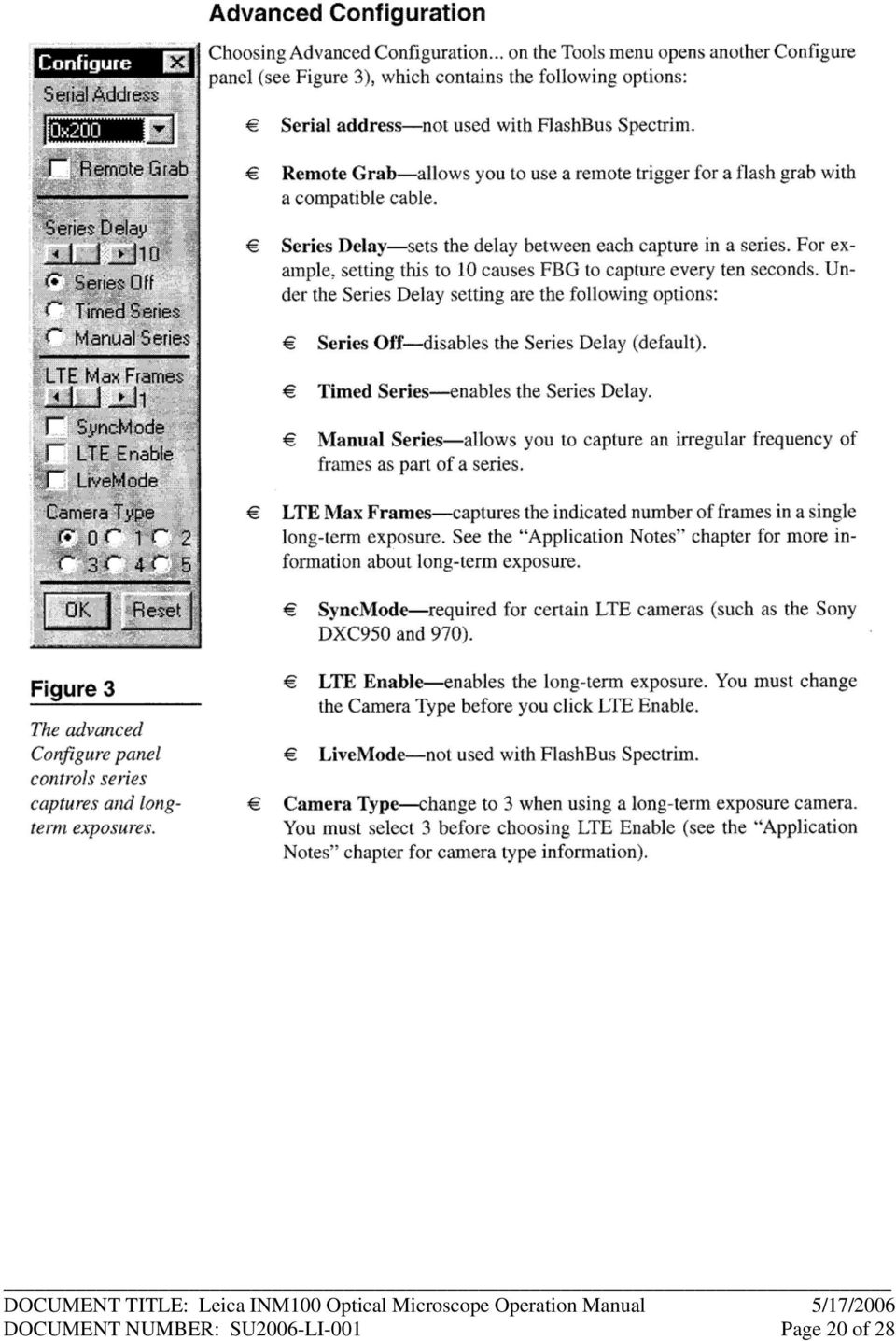
20 DOCUMENT NUMBER: SU2006-LI-001 Page 20 of 28
21 DOCUMENT NUMBER: SU2006-LI-001 Page 21 of 28
22 DOCUMENT NUMBER: SU2006-LI-001 Page 22 of 28
23 Appendix C* Video Camera Operation Manual (For Staff Only) Reference Material for Video Camera *Included for staff debug operations. DOCUMENT NUMBER: SU2006-LI-001 Page 23 of 28
24 DOCUMENT NUMBER: SU2006-LI-001 Page 24 of 28
25 DOCUMENT NUMBER: SU2006-LI-001 Page 25 of 28
26 DOCUMENT NUMBER: SU2006-LI-001 Page 26 of 28
27 DOCUMENT NUMBER: SU2006-LI-001 Page 27 of 28
28 DOCUMENT NUMBER: SU2006-LI-001 Page 28 of 28
Care and Use of the Compound Microscope
 Revised Fall 2011 Care and Use of the Compound Microscope Objectives After completing this lab students should be able to 1. properly clean and carry a compound and dissecting microscope. 2. focus a specimen
MT-30 & MT-90 Series. Advanced Academic Microscopes/ Advanced Academic Polarizing Microscope INSTRUCTION MANUAL
 Introduction With your purchase of an MT-30/MT-90 series type microscope you have chosen for a quality product. The MT-30/MT-90 series type microscopes are developed for use at schools and laboratories.
National Optical & Scientific Instruments Inc. 11113 Landmark 35 Drive San Antonio, Texas 78233 Phone (210) 590-9010 Fax (210) 590-1104
 590-9010 Fax (210) 590-1104") National Optical & Scientific Instruments Inc. 11113 Landmark 35 Drive San Antonio, Texas 78233 Phone (210) 590-9010 Fax (210) 590-1104 INSTRUCTIONS FOR MODELS 106, 106-L 107, 107-L 108, 108-L 109-L ELEMENTARY
National Optical & Scientific Instruments Inc. 11113 Landmark 35 Drive San Antonio, Texas 78233 Phone (210) 590-9010 Fax (210) 590-1104 INSTRUCTIONS FOR MODELS 106, 106-L 107, 107-L 108, 108-L 109-L ELEMENTARY
Chapter 1 Parts C. Robert Bagnell, Jr., Ph.D., 2012
 Chapter 1 Parts C. Robert Bagnell, Jr., Ph.D., 2012 Figure 1.1 illustrates the parts of an upright compound microscope and indicates the terminology that I use in these notes. Figure 1.1. Parts of a Compound
MICROSCOPY. To demonstrate skill in the proper utilization of a light microscope.
 MICROSCOPY I. OBJECTIVES To demonstrate skill in the proper utilization of a light microscope. To demonstrate skill in the use of ocular and stage micrometers for measurements of cell size. To recognize
EXPERIMENT #1: MICROSCOPY
 EXPERIMENT #1: MICROSCOPY Brightfield Compound Light Microscope The light microscope is an important tool in the study of microorganisms. The compound light microscope uses visible light to directly illuminate
18-270mm F/3.5-6.3 Di II VC PZD for Canon, Nikon (Model B008) 18-270mm F/3.5-6.3 Di II PZD for Sony (Model B008)
 18-270mm F/3.5-6.3 Di II PZD for Sony (Model B008)") R 18-270mm F/3.5-6.3 Di II VC PZD for Canon, Nikon (Model B008) 18-270mm F/3.5-6.3 Di II PZD for Sony (Model B008) Thank you for purchasing the Tamron lens as the latest addition to your photographic equipment.
R 18-270mm F/3.5-6.3 Di II VC PZD for Canon, Nikon (Model B008) 18-270mm F/3.5-6.3 Di II PZD for Sony (Model B008) Thank you for purchasing the Tamron lens as the latest addition to your photographic equipment.
AF 70~300 mm F/4-5.6 Di LD Macro 1:2 (Model A17)
") AF 70~300 mm F/4-5.6 Di LD Macro 1:2 (Model A17) Thank you for purchasing the Tamron lens as the latest addition to your photographic equipment. Di II lens (Digitally Integrated) series are designed for
AF 70~300 mm F/4-5.6 Di LD Macro 1:2 (Model A17) Thank you for purchasing the Tamron lens as the latest addition to your photographic equipment. Di II lens (Digitally Integrated) series are designed for
SP AF 300mm F/2.8 LD [IF] for Canon (Model 360EE)
![SP AF 300mm F/2.8 LD [IF] for Canon (Model 360EE)](/thumbs/40/21493790.jpg "SP AF 300mm F/2.8 LD [IF] for Canon (Model 360EE)") SP AF 300mm F/2.8 LD [IF] for Canon (Model 360EE) We greatly appreciate your purchase of this Tamron lens. The Tamron SP AF 300mm F/2.8 LD [IF] is a fast telephoto lens developed for Canon AF single-reflex
SP AF 300mm F/2.8 LD [IF] for Canon (Model 360EE) We greatly appreciate your purchase of this Tamron lens. The Tamron SP AF 300mm F/2.8 LD [IF] is a fast telephoto lens developed for Canon AF single-reflex
THE COMPOUND MICROSCOPE
 THE COMPOUND MICROSCOPE In microbiology, the microscope plays an important role in allowing us to see tiny objects that are normally invisible to the naked eye. It is essential for students to learn how
National Optical & Scientific Instruments Inc. 11113 Landmark 35 Drive San Antonio, Texas 78233 Phone (210) 590-9010 Fax (210) 590-1104
 590-9010 Fax (210) 590-1104") National Optical & Scientific Instruments Inc. 11113 Landmark 35 Drive San Antonio, Texas 78233 Phone (210) 590-9010 Fax (210) 590-1104 INSTRUCTIONS FOR MODELS 156, 156-S, 157 COMPOUND BIOLOGICAL MICROSCOPES
National Optical & Scientific Instruments Inc. 11113 Landmark 35 Drive San Antonio, Texas 78233 Phone (210) 590-9010 Fax (210) 590-1104 INSTRUCTIONS FOR MODELS 156, 156-S, 157 COMPOUND BIOLOGICAL MICROSCOPES
Name Class Date Laboratory Investigation 4B Chapter 4: Cell Structure
 Name Class Date Laboratory Investigation 4B Chapter 4: Cell Structure The Microscope: A Tool of the Scientist You may refer to pages 66-67, 72-73 in your textbook for a general discussion of microscopes.
Microscopy. MICROSCOPY Light Electron Tunnelling Atomic Force RESOLVE: => INCREASE CONTRAST BIODIVERSITY I BIOL1051 MAJOR FUNCTIONS OF MICROSCOPES
 BIODIVERSITY I BIOL1051 Microscopy Professor Marc C. Lavoie [email protected] MAJOR FUNCTIONS OF MICROSCOPES MAGNIFY RESOLVE: => INCREASE CONTRAST Microscopy 1. Eyepieces 2. Diopter adjustment
User Guide LUXXOR VIDEO MICROSCOPE. 2 Luxxor Video Microscope Set Up
 2 Luxxor Video Microscope Set Up User Guide LUXXOR VIDEO MICROSCOPE Column When removed from its packaging, the Luxxor Video Microscope will be configured as shown, with the Vertical Slide and Slide Stop
VISM Evolution Scope Series
 1 VISM Evolution Scope Series Congratulations on the purchase of your New VISM Evolution (EVO) Series Scope! The EVO Series of Scopes give you many great high end features and various magnification ranges
Compound microscope (Hund)
") 1 2 3 4 5 6 7 8 9 10 11 12 13 14 Compound microscope (Hund) 15 16 17 18 19 20 1) Eyepieces (magnifies 10x), one with diopter adjustment, 2) Interp[upillary adjustment, 3) Head, 4) Revolving nosepiece,
1 2 3 4 5 6 7 8 9 10 11 12 13 14 Compound microscope (Hund) 15 16 17 18 19 20 1) Eyepieces (magnifies 10x), one with diopter adjustment, 2) Interp[upillary adjustment, 3) Head, 4) Revolving nosepiece,
VISM CQB Scope Series
 1 VISM CQB Scope Series Congratulations on the purchase of your new VISM CQB Scope! The CQB Series of Scopes give you many great options so you can choose the scope that best fits your needs. Backed by
TS-E24mm f/3.5l TS-E45mm f/2.8 TS-E90mm f/2.8 Instructions
 TS-E24mm f/3.5l TS-E45mm f/2.8 TS-E90mm f/2.8 ENG Instructions Thank you for purchasing a Canon product. Canon s TS-E lenses are tilt-shift lenses designed for EOS cameras. The tilt-shift mechanism enables
SP AF 17~50 mm F/2.8 XR Di-II LD Aspherical [IF] (Model A16)
![SP AF 17~50 mm F/2.8 XR Di-II LD Aspherical [IF] (Model A16)](/thumbs/40/20837175.jpg "SP AF 17~50 mm F/2.8 XR Di-II LD Aspherical [IF] (Model A16)") SP AF 17~50 mm F/2.8 XR Di-II LD Aspherical [IF] (Model A16) Thank you for purchasing the Tamron lens as the latest addition to your photographic equipment. Di II lens (Digitally Intigrated) series are
SP AF 17~50 mm F/2.8 XR Di-II LD Aspherical [IF] (Model A16) Thank you for purchasing the Tamron lens as the latest addition to your photographic equipment. Di II lens (Digitally Intigrated) series are
A new advance in routine inspections INVERTED MICROSCOPE CKX41/CKX31
 A new advance in routine inspections INVERTED MICROSCOPE CKX41/CKX31 Phase contrast Relief contrast Incorporation of advanced UIS2 optics ensures the highest level of clarity for cell checking applications.
How To Use An Asbestos Microscope
 Asbestos Microscopes and Accessories Pyser-SGI has been supplying microscopes and accessories into Asbestos Laboratories for over 40 years PS12 Stage Micrometer with UKAS Certificate of Calibration - For
Infrared Viewers. Manual
 Infrared Viewers Manual Contents Introduction 3 How it works 3 IR viewer in comparison with a CCD camera 4 Visualization of infrared laser beam in mid-air 4 Power Density 5 Spectral sensitivity 6 Operation
National Optical & Scientific Instrument Inc. 11113 Landmark 35 Drive San Antonio, Texas 78233 Phone (210) 590-9010 Fax (210) 590-1104
 590-9010 Fax (210) 590-1104") National Optical & Scientific Instrument Inc. 11113 Landmark 35 Drive San Antonio, Texas 78233 Phone (210) 590-9010 Fax (210) 590-1104 INSTRUCTIONS FOR STEREOSCOPIC MICROSCOPES MODEL NUMBERS 400 400TL
National Optical & Scientific Instrument Inc. 11113 Landmark 35 Drive San Antonio, Texas 78233 Phone (210) 590-9010 Fax (210) 590-1104 INSTRUCTIONS FOR STEREOSCOPIC MICROSCOPES MODEL NUMBERS 400 400TL
OPERATING INSTRUCTIONS XJL 101/101A REFLECTED LIGHT METALLURGICAL MICROSCOPE
 OPERATING INSTRUCTIONS XJL 0/0A REFLECTED LIGHT METALLURGICAL MICROSCOPE M.R.C.LTD. OFFICES: HAHYSTADRUT 84, HOLON 58394 P.O.B. 684, TEL-AVIV 606, ISRAEL TEL: 97-3-559305,97-3-55955 FAX: 97-3-559459 www.mrclab.com
SP AF 90mm F/2.8 Di Macro 1:1 (Model 272E)
") SP AF 90mm F/2.8 Di Macro 1:1 (Model 272E) Thank you for purchasing this Tamron lens as the latest addition to your photographic equipment. Before using your new lens, please read the contents of this
SP AF 90mm F/2.8 Di Macro 1:1 (Model 272E) Thank you for purchasing this Tamron lens as the latest addition to your photographic equipment. Before using your new lens, please read the contents of this
Features: Mounting the Optic
 MICRO GREEN DOT with INTEGRATED RED LASER The Patented Micro Green Dot with Integrated Red Laser is a compact optical system packed with many features. The Green Dot is designed as the primary targeting
MITOSIS IN ONION ROOT TIP CELLS: AN INTRODUCTION TO LIGHT MICROSCOPY
 MITOSIS IN ONION ROOT TIP CELLS: AN INTRODUCTION TO LIGHT MICROSCOPY Adapted from Foundations of Biology I; Lab 6 Introduction to Microscopy Dr. John Robertson, Westminster College Biology Department,
PlaneWave CDK Telescope Instructions CDK12.5, 17, 20 and 24
 PlaneWave CDK Telescope Instructions CDK12.5, 17, 20 and 24 V112712 1 Collimation and Secondary Spacing Procedure The CDK optical design has four optical elements shown in Figure 1. The primary mirror
Measuring. User Manual
 0 1 2 3 4 5 6 7 8 9 10 11 Measuring User Manual Accessories for measuring tasks Stage micrometer (1) for calibration Graticules with various measuring pitches (2) in mm and inches Graticule with mesh (3)
National Optical & Scientific Instruments Inc. 11113 Landmark 35 Drive San Antonio, Texas 78233 Phone (210) 590-9010 Fax (210) 590-1104
 590-9010 Fax (210) 590-1104") National Optical & Scientific Instruments Inc. 11113 Landmark 35 Drive San Antonio, Texas 78233 Phone (210) 590-9010 Fax (210) 590-1104 INSTRUCTIONS FOR MODELS 130, 131, 132, 138 & 139 COMPOUND MICROSCOPES
National Optical & Scientific Instruments Inc. 11113 Landmark 35 Drive San Antonio, Texas 78233 Phone (210) 590-9010 Fax (210) 590-1104 INSTRUCTIONS FOR MODELS 130, 131, 132, 138 & 139 COMPOUND MICROSCOPES
Scanners and How to Use Them
 Written by Jonathan Sachs Copyright 1996-1999 Digital Light & Color Introduction A scanner is a device that converts images to a digital file you can use with your computer. There are many different types
Rodenstock Photo Optics
 Rogonar Rogonar-S Rodagon Apo-Rodagon N Rodagon-WA Apo-Rodagon-D Accessories: Modular-Focus Lenses for Enlarging, CCD Photos and Video To reproduce analog photographs as pictures on paper requires two
Smart Cam, CC-Smart-Cam, and Smart Cam Packages Installation and Quick Start Operating Instructions
 Smart Cam, CC-Smart-Cam, and Smart Cam Packages Installation and Quick Start Operating Instructions 12/12/2013 FRONT VIEW BACK VIEW TYPICAL PACKAGE 1 Installation Assemble video coupler to the zoom body
Eye Tracking Instructions
 Eye Tracking Instructions [1] Check to make sure that the eye tracker is properly connected and plugged in. Plug in the eye tracker power adaptor (the green light should be on. Make sure that the yellow
Science In Action 8 Unit C - Light and Optical Systems. 1.1 The Challenge of light
 1.1 The Challenge of light 1. Pythagoras' thoughts about light were proven wrong because it was impossible to see A. the light beams B. dark objects C. in the dark D. shiny objects 2. Sir Isaac Newton
ST-80 MICROSCOPE With Electronic Eyepiece #6810. User Guide
 ST-80 MICROSCOPE With Electronic Eyepiece #6810 User Guide The ST-80 Microscope Thank you for purchasing your student microscope from ioptron. The ST-80 Microscope is both versatile and easy to use with
MACRO PHOTO LENS. MP-E 65mm f/2.8 1-5 ENG. Instruction
 MACRO PHOTO LENS MP-E 65mm f/2.8 1-5 ENG Instruction Thank you for purchasing a Canon product. Canon Macro Photo Lens MP-E 65mm f/2.8 1-5 is a high-magnification macro lens that can magnify the subject
Handheld USB Digital Endoscope/Microscope
 Handheld USB Digital Endoscope/Microscope ehev1-usbplus User s Manual INTRODUCTION FUNCTIONS AND APPLICATIONS The USB Digital Endoscope/Microscope is a new electronic product for the micro observations.
WAVELENGTH OF LIGHT - DIFFRACTION GRATING
 PURPOSE In this experiment we will use the diffraction grating and the spectrometer to measure wavelengths in the mercury spectrum. THEORY A diffraction grating is essentially a series of parallel equidistant
VICKERS HARDNESS TESTER. HBS HBW Kc
 ICKERS HARDNESS TESTER H HK HBS HBW Kc Clean Touch Panel coordinated with highly integrated PC board. Measuring procedures, conditions and data are displayed clearly. (F-800 Series) Accurate light load
Protocol for Microscope Calibration
 Protocol for Microscope Calibration A properly calibrated system is essential for successful and efficient software use. The following are step by step instructions on how to calibrate the hardware using
P R E A M B L E. Facilitated workshop problems for class discussion (1.5 hours)
") INSURANCE SCAM OPTICS - LABORATORY INVESTIGATION P R E A M B L E The original form of the problem is an Experimental Group Research Project, undertaken by students organised into small groups working as
INSURANCE SCAM OPTICS - LABORATORY INVESTIGATION P R E A M B L E The original form of the problem is an Experimental Group Research Project, undertaken by students organised into small groups working as
Installation and use of Millett Tactical TRS-1 and TRS-2 scopes TRS-1 TRS-2. Before starting, make sure firearm is UNLOADED!!
 I N S T R U C T I O N a n d O P E R A T I O N TRS-1 TRS-2 Tactical Rifle scope Installation and use of Millett Tactical TRS-1 and TRS-2 scopes TRS-1 TRS-2 Before starting, make sure firearm is UNLOADED!!
The Krasnogorsk-3. Operating Instructions. Sold by NCS Products, New York
 The Krasnogorsk-3 Operating Instructions Sold by NCS Products, New York [6] Viewfinder [7] Light Meter FPS Dial [8] Light Meter Power Switch [9] Light Meter ASA/ISO Knob [10] Pistol Grip [11] Lens Focus
MAINTENANCE & TROUBLESHOOTING
 MAINTENANCE & TROUBLESHOOTING This section describes how to: clean the lens clean the fan intake filter replace the projection lamp replace the batteries in the remote control use the Kensington lock feature
FirstView 3 Reflector Telescope Owner s Manual
 FirstView 3 Reflector Telescope Owner s Manual 1. Horizontal Locking Auxiliary Screw 2. Main Mount 3. Pitching Auxiliary Knob 4. Pitching Shaft Screw 5. Rack and Pinion Focusing Knob 6. Thumb Nut for Finder
Light and its effects
 Light and its effects Light and the speed of light Shadows Shadow films Pinhole camera (1) Pinhole camera (2) Reflection of light Image in a plane mirror An image in a plane mirror is: (i) the same size
EF70-300mm f/4-5.6 IS USM
 EF70-300mm f/4-5.6 IS USM ENG Instruction Thank you for purchasing a Canon product. Dedicated to EOS cameras, the Canon EF70-300mm f/4-5.6 IS USM lens is a highperformance telephoto zoom lens equipped
Single Lens Reflex (SLR) Camera
 Camera") 690 Single Lens Reflex (SLR) Camera User Guide 690 Single Lens Reflex (SLR) Camera User Guide Contents IMPORTANT SAFEGUARDS: FCC Notice 1 Camera Features 1 Camera Parts 1 Opening the Camera 2 Closing the
690 Single Lens Reflex (SLR) Camera User Guide 690 Single Lens Reflex (SLR) Camera User Guide Contents IMPORTANT SAFEGUARDS: FCC Notice 1 Camera Features 1 Camera Parts 1 Opening the Camera 2 Closing the
RL HW / RL HW+ / RL HGW / RL HV / RL HVPW/RL HVPW-G
 Auto-Levelling Rotary Laser Level RL HW / RL HW+ / RL HGW / RL HV / RL HVPW/RL HVPW-G 77-496 / 77-429 / 77-439 / 77-497 / 77-427/ 77-441 Please read these instructions before operating the product Auto-Levelling
Basics to Using the View Camera
 Walker Evans at work Using the View Camera Basics to Using the View Camera Because of the large-scale nature of the view camera, it is necessary to follow basic steps in setting-up the camera in order
M A R C O. CP-670 AUTOMATIC CHART PROJECTOR Instruction Manual
 M A R C O CP-670 AUTOMATIC CHART PROJECTOR Instruction Manual CONTENTS GENERAL DESCRIPTION............... 1 INSTALLATION...................... 2 Mounting the Projector Positioning the Projector Positioning
Chapter 17: Light and Image Formation
 Chapter 17: Light and Image Formation 1. When light enters a medium with a higher index of refraction it is A. absorbed. B. bent away from the normal. C. bent towards from the normal. D. continues in the
Operating Manual for UVEX-p (JAN Scientific, Inc. Aug 2014)
") Operating Manual for UVEX-p (JAN Scientific, Inc. Aug 2014) [The beige shaded areas introduce the user interface in detail. For turn on and run operation, you may skip these descriptions. The blue shaded
Operating Manual for UVEX-p (JAN Scientific, Inc. Aug 2014) [The beige shaded areas introduce the user interface in detail. For turn on and run operation, you may skip these descriptions. The blue shaded
Exercise 2. The Compound Light Microscope
 6 Exercise 2 The Compound Light Microscope INTRODUCTION: Student Learning Objectives: After completing this exercise students will: a. Demonstrate proficient use of the microscope using low, high dry,
AP Physics B Ch. 23 and Ch. 24 Geometric Optics and Wave Nature of Light
 AP Physics B Ch. 23 and Ch. 24 Geometric Optics and Wave Nature of Light Name: Period: Date: MULTIPLE CHOICE. Choose the one alternative that best completes the statement or answers the question. 1) Reflection,
Be careful not to scratch or hit front edge of the side viewing micro prisms onto hard objects!
 Instructions Manual Flexia BGA Inspection Systems This manual describes how to use Flexia BGA Inspection System Optilia Instruments 1 AB Contents 1. Safety and maintenance Instructions 3 2. About Flexia
Pictorial User s Guide
 S-T IMAGING Pictorial User s Guide Copyright 2008 ST Imaging, Inc. a division of Digital Check Corp. All Rights Reserved. Table of Contents Getting Started... 1 Adjust for Viewing...1 Loading Microfilm...2
Motion Activated Camera User Manual
 Brinno MAC200 User Manual Last Modified on 12/23/2015 7:51 pm EST Motion Activated Camera User Manual www.brinno.com Register@online http://www.brinno.com/support/register.html contact us: [email protected]
ENGINEERING METROLOGY
 ENGINEERING METROLOGY ACADEMIC YEAR 92-93, SEMESTER ONE COORDINATE MEASURING MACHINES OPTICAL MEASUREMENT SYSTEMS; DEPARTMENT OF MECHANICAL ENGINEERING ISFAHAN UNIVERSITY OF TECHNOLOGY Coordinate Measuring
FIRERAY 2000 Installation Guide
 FIRERAY 2000 Installation Guide Features Range 33ft to 330 ft. 24Vdc operation Selectable alarm thresholds Low current consumption Ground level electronics Manual or Automatic reset System Description
The Vortex Spitfire 1x Prism Scope
 REPLACE image The Vortex Spitfire 1x Prism Scope Perfect for the AR platform, the Vortex Spitfire 1x prism scope combines a compact, prism-based design with the intuitive, glass-etched DRT (Dual Ring Tactical)
Interference. Physics 102 Workshop #3. General Instructions
 Interference Physics 102 Workshop #3 Name: Lab Partner(s): Instructor: Time of Workshop: General Instructions Workshop exercises are to be carried out in groups of three. One report per group is due by
GLobAL Dental Microscopes. Dentists First Choice
 GLobAL Dental Microscopes Dentists First Choice Great prospects and an even better view There is something in every GLobAL dental microscope: Your high standard! That s why GLOBAL has only one priority:
EXPERIMENT O-6. Michelson Interferometer. Abstract. References. Pre-Lab
 EXPERIMENT O-6 Michelson Interferometer Abstract A Michelson interferometer, constructed by the student, is used to measure the wavelength of He-Ne laser light and the index of refraction of a flat transparent
MAINTENANCE & TROUBLESHOOTING
 MAINTENANCE & TROUBLESHOOTING This section describes how to: clean the lens replace the projection lamp replace the batteries in the remote use the security lock feature troubleshoot the projector Cleaning
Firearms & Tool Marks Comparison Microscope. Discovery. Leeds Forensic Systems. Your Forensic Imaging Source
 Firearms & Tool Marks Comparison Microscope Leeds Forensic Systems Your Forensic Imaging Source Leeds Discovery The Leeds Discovery Firearms & Tool Marks Comparison Microscope is an innovative microscope
Filters for Digital Photography
 Filters for Digital Photography LICHTFILTER Whether for analog or Digital Photography: The best results are achieved by using correction filters - not by digitally enhancing in a software program as once
Microscope Lab Introduction to the Microscope Lab Activity
 Microscope Lab Introduction to the Microscope Lab Activity Wendy Kim 3B 24 Sep 2010 http://www.mainsgate.com/spacebio/modules/gs_resource/ CellDivisionMetaphase.jpeg 1 Introduction Microscope is a tool
Physics 441/2: Transmission Electron Microscope
 Physics 441/2: Transmission Electron Microscope Introduction In this experiment we will explore the use of transmission electron microscopy (TEM) to take us into the world of ultrasmall structures. This
Tube Control Measurement, Sorting Modular System for Glass Tube
 Tube Control Measurement, Sorting Modular System for Glass Tube Tube Control is a modular designed system of settled instruments and modules. It comprises measuring instruments for the tube dimensions,
The Basics of Scanning Electron Microscopy
 The Basics of Scanning Electron Microscopy The small scanning electron microscope is easy to use because almost every variable is pre-set: the acceleration voltage is always 15kV, it has only a single
Vandal-Proof IR Dome Camera
 Vandal-Proof IR Dome Camera Instruction Manual VER.:1.0, NO.:040118 Thank you very much for purchasing our product. Before operating this product, please read this instruction manual carefully to ensure
TEC APO140. This telescope is closer to optical perfection more than any instrument I have ever used before. R.Renzi, Italy.
 140 manuals 2013_110 manuals 1/13/2013 10:40 PM Page 1 TEC APO140 This telescope is closer to optical perfection more than any instrument I have ever used before. R.Renzi, Italy. OWNER S MANUAL 2013 140
THE BOHR QUANTUM MODEL
 THE BOHR QUANTUM MODEL INTRODUCTION When light from a low-pressure gas is subject to an electric discharge, a discrete line spectrum is emitted. When light from such a low-pressure gas is examined with
EF70-200mm F2.8L IS USM. Instruction
 EF70-200mm F2.8L IS USM Instruction Thank you for purchasing a Canon USM lens. The Canon EF 70-200mm f/2.8l IS USM is a high-performance, telephoto zoom lens dedicated to Canon EOS cameras. It is equipped
The Applied Imaging Cytogenetic Workstation
 The Applied Imaging Cytogenetic Workstation Introduction to the Genus F.I.S.H. Imaging System. The Genus Imaging System is a powerful and easy way to capture Fluorescence in-situ Hybridisation pictures
Quick Start Guide. Digital Inverted Microscope. The Microscope Evolved.
 Digital Inverted Microscope Quick Start Guide 18421 Bothell-Everett Hwy. Suite 150 Mill Creek, WA 98012-6825 Phone: (866) 614-4022 or (425) 368-0444 Fax: (425) 368-0555 E-mail: [email protected] Web: www.amgmicro.com
Micro Cam Software. User Manual V1.3
 Micro Cam Software User Manual V1.3 CONTENT CHAPTER 1: MICRO CAM SOFTWARE INSTALLATION AND CONNECTION... - 1-1.1 SOFTWARE MICRO CAM INSTALLATION... - 1-1.2 WIRED DEVICE CONNECTION... - 4-1.3 SOFTWARE OPERATION
Underwater Housing for Sony RX100 III, RX100 IV
 Underwater Housing for Sony RX100 III, RX100 IV Product Number 6215.04 Product Registration Please register your product at ikelite.com within 15 days of purchase. Our product registration database is
MAVO-MONITOR / MAVO-SPOT Instrument Set for Contact or Distant Measurements of Luminances
 Operating Instructions MAVO-MONITOR / MAVO-SPOT Instrument Set for Contact or Distant Measurements of Luminances 15043 1/1.00 10 9 8 1 7 6 1 Display 2 Slider switch cd/m² segment test 3 ON/OFF switch 4
EPSON SCANNING TIPS AND TROUBLESHOOTING GUIDE Epson Perfection 3170 Scanner
 EPSON SCANNING TIPS AND TROUBLESHOOTING GUIDE Epson Perfection 3170 Scanner SELECT A SUITABLE RESOLUTION The best scanning resolution depends on the purpose of the scan. When you specify a high resolution,
Microscopy and Cellular Morphology
 Microscopy and Cellular Morphology As we discussed in class, many organisms on the planet exist as single cells and are referred to as microorganisms bacteria, protozoans, among others. When a single microorganism
LBS-300 Beam Sampler for C-mount Cameras. YAG Focal Spot Analysis Adapter. User Notes
 LBS-300 Beam Sampler for C-mount Cameras P/N SP90183, SP90184, SP90185 and SP90186 YAG Focal Spot Analysis Adapter P/N SP90187, SP90188, SP90189, SP90190, SP90191 User Notes Ophir-Spiricon Inc. 60 West
Written By: Walter Galan
 ipad 2 GSM Front Panel Replacement Replace the front panel in your ipad 2 GSM. Written By: Walter Galan INTRODUCTION Note: this is a complete guide for replacing a plain front panel. If you have a Front
HP Scanjet G4000 series. User Guide
 HP Scanjet G4000 series User Guide Contents 1 How to use the scanner...2 Where to get additional information...2 Accessibility...2 How to use the HP Photosmart software...3 Front panel and accessories
Digital Photo Picture Frame. Operation Manual
 Digital Photo Picture Frame Operation Manual 20070309 CONGRATULATIONS on your purchase of a Polaroid 7 LCD Digital Photo Picture Frame. Please read carefully and follow all warnings and instructions in
Chapter 4. Microscopy, Staining, and Classification. Lecture prepared by Mindy Miller-Kittrell North Carolina State University
 Chapter 4 Microscopy, Staining, and Classification 2012 Pearson Education Inc. Lecture prepared by Mindy Miller-Kittrell North Carolina State University Microscopy and Staining 2012 Pearson Education Inc.
Melting Point. Electrothermal PRODUCT SPECIFICATIONS OPERATION
 M A N U A L M E L - T E M P THE LOWEST COST MELTING POINT APPARATUS FOUND ANYWHERE! Low cost unit Temperature range to 500 C Aluminum casting conducts and radiates heat uniformly to capillaries and thermometer.
EF24-105mm f/4l IS USM
 EF24-105mm f/4l IS USM ENG Instruction Thank you for purchasing a Canon product. The Canon EF24-105mm f/4l IS USM lens is a high-performance standard zoom lens developed for EOS cameras. It is equipped
Bar Code Label Detection. Size and Edge Detection APPLICATIONS
 Bar Code Label Detection The EE-SY169(-A) and EE-SX199 sensors are used for bar code label detection. The EE-SX199 detects the absence or presence of labels (see Bar Code Printer illustration at right).
Rodenstock Photo Optics
 Apo-Sironar-S Apo-Macro-Sironar Apo-Grandagon Grandagon-N Accessories: Center filters Accessories: Focus-Mount Lenses for Analog Professional Photography Even in the age of digital photography, the professional
Chapter 12 Filters for FISH Imaging
 Chapter 12 Filters for FISH Imaging Dan Osborn The application of in situ hybridization (ISH) has advanced from short lived, non-specific isotopic methods, to very specific, long lived, multiple color
EF-S18-55mm f/3.5-5.6 IS II COPY ENG. Instruction
 EF-S18-55mm f/3.5-5.6 IS II ENG Instruction Thank you for purchasing a Canon product. The Canon EF-S18-55mm f/3.5-5.6 IS II lens is a high-performance standard zoom lens developed for digital SLRs compatible
EF-S18-135mm f/3.5-5.6 IS
 EF-S18-135mm f/3.5-5.6 IS ENG Instruction Thank you for purchasing a Canon product. The Canon EF-S18-135mm f/3.5-5.6 IS lens is a high-performance high-magnification zoom lens equipped with an Image Stabilizer,
STAAR Science Tutorial 30 TEK 8.8C: Electromagnetic Waves
 Name: Teacher: Pd. Date: STAAR Science Tutorial 30 TEK 8.8C: Electromagnetic Waves TEK 8.8C: Explore how different wavelengths of the electromagnetic spectrum such as light and radio waves are used to
Example of SOP for IR Laser
 Example of SOP for IR Laser Standard Operating Procedures (SOP) for Class 4 HPD semiconductor Laser Manufacturer HPD Building & Room Number EH&S 101 Model Number HPD-1/100/975 Laser Class 4 Serial Number
- 2 - IMPORTANT SAFETY REMINDERS
 USER MANUAL IMPORTANT SAFETY REMINDERS This appliance should only be used for domestic cleaning, as described in this user guide. Please ensure that this guide is fully understood before operating the
Application Report: Running µshape TM on a VF-20 Interferometer
 : Running µshape TM on a VF-20 Interferometer General This report describes how a fiber interferometer from Arden Photonics Ltd was used together with the µshape TM Generic software package. The VF-20
Original Assembly Guide
 TCT Multipurpose Single Bevel Sliding Compound Mitre Saw Original Assembly Guide Read instructions before assembling this tool. Table of Contents GB Assembly Guide Read instructions before assembling this