SPUTTERING PROTOCOLS
|
|
|
- Susan Butler
- 7 years ago
- Views:
Transcription
1 K550 SPUTTER COA TER INSTRUCTION MANUAL SECTION 1 DESCRIPTION SECTION 2 INSTALLATION SECTION 3 OPERATION SECTION 4 SPUTTERING PROTOCOLS SECTION 5 SERVICE AND MAINTENANCE SECTION 6 SPARES AND ACCESSORIES SECTION 7 APPENDIX SECTION 8 REFERENCES

2 C E Declaration: This Equipment of this Design and manufacture and marked CE, conforms with the requirements of the European Directives EMC 89/336/EEC & L VD 73/23/EEC. This Equipment will "fail safe" in the presence of excessive RF, Electrostatic Discharge or Mains Transients. While a loss of function could occur under extreme circumstances the Equipment's operation will be fully recoverable under normal operating conditions. A This Mains Lead. Equipment must be Earthed and fitted with the correct lead for the country of operation. This will normally be achieved from the correct mains supply socket This Equipment is normally supplied from 3 pin supply including Earth. If only 2 pin supply is available a separate Earth must be fitted. The supplementary Earth stud can be used to facilitate this requirement. Output: This is for the pump supply only and is the mains voltage at a maximum of 8 Amps.

3 DESCRIPTION SECTION 1 The K550 system employs a Magnetron Target Assembly which enhances the efficiency of the process using low voltages, and giving a fine grain, cool sputtering, without the need to cool the target or the specimen stage. The specimen height is adjustable in discreet steps, accommodates a range of specimen and stubs, which together with pre-selectable parameters and automatic control, gives defined and repeatable film thickness depositions. The Instrument is fitted with 60mm Dia. x O.1mm. Thick Gold quick change target giving optimum consumable cost performance. The integrated Instrument panel and plug-in electronics, maximize 'up-time' and, with user friendly designs, ensures satisfactory multi-user discipline. The sputtering parameters can be pre-set, including the gas bleed needle valve which has electromagnetic valve back-up. The sputtering head is interlocked, and the system can easily accommodate the K250 Carbon Coating Attachment. The independent vacuum pump is controlled by the Instrument throughout the fully automatic coating cycle.

4 INSTALLATION SECTION 2 It is important that this equipment is installed and operated by skilled personnel in accordance with these instructions. Failure to do so may result in damage, and impair protection provided. 'If in doubt - ASK'. A suitable location should be provided for the unit - either operated on a bench or the recommended trolley. The total weight of the system is 25 Kg. The system operating environment ambient temperature ranqe is 150C to 250C in a non condensing relative humidity of not more than 75%. Sufficient ventilation is required, and positioning should be out of direct sunlight. The system is rated for continuous operation other than those supplies specified. See Section Preliminary Checks Remove Instrument from packing and place inspection for any signs of transit damage. on appropriate operational position. Carry out visual Remove Accessories pack, and check contents against K550 Accessories Pack Shipping list. Ensure that all areas of the Instrument are free of loose packaging material. Check specifically the Instrument chamber, glass cylinder, and 'L' gaskets. (Do not use vacuum grease on gaskets). Where a vacuum pump has been supplied, carry out preliminary checks in accordance with manufacturers recommendations. (Refer to: Appendix 7. For pump plug wiring.) : If you are using existing or alternative vacuum pump, and have any difficulty with connections, please advise.

5 2.2 Connections. Connections should only be made in accordance with instructions. Refer to: Appendix 7.1 Figure 1 Rear Panel Diagram. For fuse ratings and voltages refer to: Appendix 7.2. Any other items on rear panel not listed are for common manufacturing and are not available for this Instrument. QI.5: A single phase AC suppl the country of operation. frequency range is: with earth is required - selected to the correct voltage for :ither nominal 240 V or nominal 120V. The voltage and

6 2.2. Connections - continued Carry out process gas connections to rear panel (Refer to: Appendix 7.1 Figure 1) with tubing and connectors provided. The connector is push-fit and will 'snap' into a locked position. It can be released by depressing the metal tongue. Argon gas is recommended at a nominal pressure cf4 p.s.i. The electrical input to the Instrument is made with the power lead provided. The Instrument connection is standard, and the lead is fitted with the appropriate plug for the country of operation. Ensure the plugs are firmly located. Check the two voltage selector switches A/B (Refer to: Appendix 7.1 Figure 1) are to the correct voltage for the country of operation which should correspond to the voltage label on the Instrument. The appropriate electrical supplies for countries are given in Appendix 7.3. The vacuum connection is made by 1 metre length of vacuum hosing. This is a push-on fit to the Instrument. Ensure that this is firmly in place to the full length of the vacuum connector. If recommended pump is used, this also has a push-on fit connector. Ensure this connector is screwed firmly in place before push fitting vacuum hosing. QI&: If you are using existing or alternative vacuum pump, and have any difficulty with connections, please advise. An Oil Mist Filter with metal adapter should be fitted to outlet of vacuum pump (See Section 6). Check that the vacuum pump is filled with correct oil. (See Section 6.) If the vacuum pump is fitted with an On/Off switch, ensure that it is left in the 'On' position as the Instrument will carry out recommended control. Ensure that the HT connector to the lid is rear panel connection. Check adjustable stage can be set in three positions. loaded location balls, and can be removed completely lower position is normally recommended. screwed firmly in place, and also screwed in firmly to the The positioning is by means of spring without any damage to the assembly. The
 are to the correct voltage for the country of operation which should correspond to the voltage label on the Instrument.")
7 2.3 Initial Operating Checks (These should be made having become familiar with the controls under Section 3). Ensure deposition control is set to minimum (fully anti-clockwise). Set timer control to maximum (fully clockwise). Switch power on with the rocker switch located on rear panel of Instrument. The neon should illuminate showing power to the Instrument. Check that the 12V. AC and 12V. DC LED's are illuminated on the front panel. Check inhibit is not initiated (LED is off). Check process gas by operating vent-stop. The process gas cylinder output gauge will drop slightly. The K550 lid will lift 'slightly' when chamber fills with Q.8S. Check vacuum pump by operating start switch. Vacuum gauge should achieve 5 x 1 O mbar within 1 minute after the initial purge has finished. Allow system to continue pumping, vacuum should reach approx. 1 x 10⁻¹ mbar (the bleed trip point) within 2 minutes. Check 'Power On' safety interlock LED is 'On' when lid is closed, and when bleed LED comes on, adjust needle valve at rear of Instrument to achieve a stable vacuum of 1 x 101mbar. When coat led comes on, increase deposition SLOWLY until a plasma (Blue) is observed at approx. 10mA. Continue increasing plasma over the range to approx. 40mA, then decrease and set at 20mA. Allow instrument to automatically time-out and vent. NQI: The sputter cycle is rated for a Max. 50mA for 5 minutes, with a duty cycle of 50%. (Off time - 5 minutes.) (If Instrument times-out in 4 minutes, restart and continue set up.) Set 2 minutes on timer, after completing set up. Select Hold-Inhibit. Select pump start, and allow vacuum to achieve better than 1 x 10⁻¹ mbar. M: Hold-Inhibit is normally only initiated when using a carbon attachment K250, or if it is considered necessary to outgas a specimen for a longer period. Release Hold-Inhibit, and observe. Vacuum should return to previously set position. Observ Instrument completes automatic cycle, coating at 20mA for 2 minutes at vacuum 1 x 10⁻¹mbar. Select pump start and observe Instrument complete an automatic cycle as pre-set.

8 OPERATION SECTION 3 Refer to: Appendix 7.1 Figure 2 Front Panel Diagram.

9 3.1 Sequence The sequence of events for a typical coating run. Assuming the Instrument has been set up as instructions under Section 2 1. The suggested parameters which should be satisfactory for general applications are as listed. (a) (b) (c) (d) (e) M: 2. (8) (b) (c) 3. Needle valve (bleed) adjustment set to give 1 x1 0-1 mbar with process at nominal 4 p.s.i. Specimen stage set to lower position. (Stage to target 45mm spacing.) Deposition current at 20mA. Deposition time 2 minutes. Typical coating 15nm (150 Angstroms). These conditions for coating thickness can be more readily determined by referring to the K550 Deposition Chart, (Appendix 7) allowing for spacing of any stub and specimen height when reading final settings. Operate pump-start Chamber will purge for 10 seconds with process gas. (Argon.) After pump down, bleed will operate, and chamber vacuum will stabilize for 60 seconds at 1 x 10⁻¹mbar. Coat will operate at deposition current of 20mA. At end of cycle. (a) (b) (c) 4. Vent-stop will operate automatically:, and purge will operate. The vacuum If further purging is required. the vent-stop can be operated manually. The vent-stop can also be operated manually to abort a run. Hold-inhibit. This is used for one of two conditions. pump will stop. (a) (b) If it is required to outgas a specimen more than the normal automatic cycle, then select Hold-Inhibit. This will inhibit system and allow chamber to be contin after initial purge. The vacuum will eventually be somewhat better than 7 x 1 When hold-inhibit is switched off, K550 will assume normal cycle. If it is required to use a K250 for carbon 'flash' evaporation, then select hold-inhibit. K550 is now used as a vacuum chamber.for carbon head. Using Carbon or Cord, outgas vacuum of 1 x 10⁻¹mbar, 7 x 10⁻²mbar and evaporation vacuums of completion, select Vent-Stop on the K550.. For full details consult separate K250 Instruction Manual
.")
10 SPUTTERING PROTOCOLS The following is only a brief outline and guide. SECTION 4 For further details consult References - Section 8. The K550 is primarily to provide conductive metal coatings for SEM microscopy. In such applications it would be common to use Aluminum Specimen Stubs. The main classification of specimen types is between 'bulk' and 'particulate'. In the case of 'bulk' specimens, a good bonding to the stub is required. In addition, although an omni-directional coating is achieved, it may be advantageous to use adhesives which are electrically conductive. Silver Dag, a Silver Loaded Conductive Paint is commonly used, but to achieve a somewhat more substantial bonding, Silver Loaded Epoxy which has good strength and electrical conductivity is advantageous. In the case of 'particulate' specimens, depending on the nature, again a thin layer of Silver Dag is suitable, with the specimens 'sprinkled' on it. Alternatively, a Cyanoacrylate or double sided tape can be used. In both cases the mounting medium is of low profile. The coating should be sufficient to make electrical contact with the specimen and stub. If this is not the case, it may be necessary to bond using one of the previously mentioned conducting adhesives. While the standard settings for Sputter Coating, mentioned in Operation Section 3, may be satisfactory for most SEM applications (giving typically 15nm (150 Angstroms) settings: 20mA. 45mm. 2mins), these can be optimized depending on the specimen. The objective being to obtain as thin and continuous conductive coating as possible to avoid obstructing detail, while giving specimen stability and avoiding charging. For very irregular specimens a slightly thicker coating may be required if charging is observed. While various settings such as time and spacing can be altered, we would recommend increasing the coating time, while maintaining the sputtering current and distances. (Giving typically 21nm (210 Angstroms) settings: 20mA. 45mm. 3mins.) For less irregular specimens and thinner coatings for fine detail, where charging does not appear as significant, then reducing the sputtering current would be the preferred method. (Giving typically 10nm (100 Angstroms) settings: 15mA. 45mm. 2 mins.) The heat input from sputtering with the K550 is very small. If it is considered the specimen is heat sensitive, then a low sputtering current, with longer time to achieve the necessary coating thickness is recommended, while maintaining maximum specimen spacing. It is not considered necessary, with the low thermal input and low sputtering voltage, to pre-cool the specimen stage. Assuming the specimen is stable at room temperature. The low sputtering voltage is to achieve low thermal input, and high resolution, small grain size coatings. Typically the grain size of is of the order of 2nm (20 Angstroms). However, as we normally require somewhat thicker coatings to achieve electrical conductivity the final resolution will be somewhat less. Alternative target materials may suggest smaller grain size, Gold/Palladium is the order of 1. 7nm (17 Angstroms), there may not necessarily be a recognizable gain in high resolution, and such coatings may be susceptible to cracking. Careful consideration should be given when using alternative material, Gold having proved particularly successful for the majority of SEM work when utilized in Instruments such as the K550.

11 SERVICE AND MAINTENANCE SECTION 5. 1 "'B.nwnBnce Check and clean the glass chamber and the 'L' gaskets as required, using Velin Tissue and foam cleanser, or similar. (See s Section chamber 6.) and (Monthly.) the 'L' gaskets as required, using Velin Tissue and foam Section 6.) (Monthly.) Do not use vacuum grease on 'L' gaskets. Check the condition of the target material. The wear will depend on use. This is mainly over an outer annulus, accounting for some 70% of the surface area. (Monthly.) When the backing plate shows at the edges. it may still be used. When this becomes excessive and sputtering is affected. the target should be replaced. : A replacementarget exchange service is offered for precious metal recovery. On return of your original target backing plate, a discount made against your new purchase. On purchase. To Chanae Taraet. Loosen the two small Allen screws around the circumference of the target holder using the Allen key provided with your spares kit. These locate into a 'V' groove in the target circumference, the target can then be removed. Replace with the new target. ensuring that the screws are tightened equally and firmly into the 'V' groove to ensure good electrical and mechanical connection. Check vacuum pump oil level. (Monthly.) Change oil every 6 months using 1 litre of Supergrade 'A'.(See Section 6.) (6 Monthly.) Check Oil Mist Filter for saturation. Change every 6 months, or more regularly as required. (See Section 6.) (This is a disposable plastic filter and cannot be reactivated.) Regularly inspect electrical power cords and plugs for general condition. CAUTION: Ensure mains electrical power is off during any maintenance and service activities. : Consumable items can be obtained from Emitech or approved Distributor. Only Emitech recommended items should be used. For technical assistance and advice - contact Emitech. Emitech Ltd., South Stour Avenue, Ashford, Kent TN23 7RS. England. Tel: Fax: **If approved Distributor not known - please contact Emitech direct for details

12 5.2 Service Routine checks. should not be necessary. In the event of non-operation, carry out the following IMPORTANT: Depending on nature of problem, disconnect power cord BEFOREcarrying out any servicing activities. 1. Check power to instrument: Neon on rear should be illuminated. 2. Check electronic supplies: 12V AC and 12V DC should be illuminated. 3. Check fuses: Refer to Appendix Check vacuum pump: Local switch should be in 'On' position. 5. Check chamber seating for vacuum leaks. 6. Check operating conditions of Instrument controls. 7. Check Allen screws to target and connections. 8. Check 'Power On' LED illuminates when lid switch is closed. This is the 'Power On' to the H.T. sputtering supply interlock. 9. Check correct conditions for sputtering have been set. 10. Check all connections. 11. Check Hold-Inhibit switch is 'Off. In the event of all checks proving negative, please contact Emitech, or your local Distributor. An Advance Delivery Modular Exchange Service Scheme is operated for the complete single module control electronics. This can be customer installed in accordance with instructions provided. NOTE: Spare items can be obtained from Emitech or approved Distributor. recommended items should be used. For technical assistance and Emitech. Only Emitech advice - contact Emitech Ltd., South Stour Avenue Ashford, Kent TN23 7RS England. Tel: Fax: **If approved distributor not known - please contact Emitech direct for details.

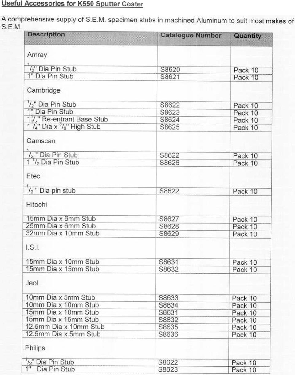
13 SPARES AND ACCESSORIES SECTION 6 The following in the current are available from Emitech, or your local Distributor, and are featured in more detail Emitech Consumables Catalogue. Copies can be sent on request. ** for special Targets please enquire.

14
15 APPENDIX SECTION Figure 1 Rear Panel Figure 2 Front Panel 7.2 Fuse Listings 7.3 Electrical Supplies World-Wide 7.4 Pump Plug Wiring 1.5 Deposition Chart

16 Q. > Ṇ - c> '0 > C" - «1&1 0 Co ;L z T 0 -' 0 :r! III J: U - UJ too «C1) I no no \II cc Do 0 w W -I CD 'C 0 u A. 0 tii I I- Z W > -. c 0 c E.. 0 'e W). '".. Z. 0. «... iii U) N IU "
 N8 0.-. IU.0. 00....... \"")
17 Ị -.- 0,.. i. m. I 0 X lliw..m.m i., :: IQ e I I.c.. i.8. I. Ị. 8; i

18 7.2 Appendix T10A fuse is preferred. May be substituted for 10A Sio-blo Ceramic - non preferred. Fuse standard leg 127, CEE4. Fuse standard CSA C22.2/UL 198G * Replacement fuses can be supplied by Emitech, or the approved Distributor.. Emitech Ltd., South Stour Avenue, Ashford, Kent TN23 7RS, England. Tel: + 44 (0) Fax:+ 44 (0) ** If approved distributor not known - please contact Emitech direct for details.

19 7.3 ElectricaI Supplies World-Wide

20 APmilDIX FIWRE 7. It 1Ut!P PIOOWIRnK; RHPUX;t:5A/CMADA (LIVE IUon> pu.x; U. K. /EUR:>PE

21 7.5 Graph Showing Expected Sputtering Rate Sputtering Deposition Rate Using Gold (Using 1x10.1mbar, target to sample spacing = 30mm) Deposition Current (ma) 70
22 SECTION 8 CRAIG,S. and HARDING G.L. (1981) Effects of Argon pressure and substrate temperature on the structure and properties of sputtered copper films. J.Vac.Sci. Technol., 19, ECHLlN, P. BROERS, A.N. and GEE, W. (1980) Improved resolution of sputter-coated metal films. Scanning Elect. Microsc. 1980; 1, PETERS, K-R. (1980). Penning of ultra thin metal films for high resolution Electron Microscopy Scanning Elect Microsc. 1980; I, SCHillER, S. HEISIG, U. and GOEDICKE, (1977). Use of the ring gap plasmatron for high rate sputtering Thin Solid Films, 40, THORNTON, J.A. (1978). Substrate heating in cylindrical magnetron sputtering sources. Thin Solid Films, 54, NOCKOlDS, C.E. MORAN, K. DOBSON, E. and PHilLIPS A. Design and operation of a high efficiency magnetron Sputter Coater. Scanning Elect.Microsc III (Available on Request)
23 Safety information for the return of Preparation Equipment and General Introduction The employer (user) is responsible for the health and safety of his employees. This also applies to all those persons who come into contact with the Preparation Equipment and Accessories either at the user's or manufacturer's premises during repair of service. The contamination of Preparation Equipment and Accessories has to be declared and the Health and Safety Declaration form completed. Health and Safety Declaration Those persons carrying out repair or service have to be informed of the condition of the components. This is the purpose of the 'Declaration of Contamination of Preparation Equipment and Accessories.'. Despatch When returning equipment the procedures set out in the Operating Instructions must be followed. For example: - Drain the vacuum pumps. - Neutralise the flushing with gas. - Remove filter elements.. Seal all outlets.. Pack glass components safely. Pack loose attachments securely for example stages. - Seal in heavy duty polythene or a bag, Despatch in suitable transport container. Return Address: F.A.O.: The Service Manager, Emitech Limited, South Stour Avenue, Ashford, Kent. TN23 7RS.
24 Declaration of Contamination of Preparation Equipment and Accessories. The repair and/or service of Preparation Equipment and Accessories can only be carried out if a correctly completed dedaration has been submitted. Non-completion will result in delay. The manufacturer reserves the right to refuse acceptance of consignments submitted for repair or maintenance work where the declaration has been omitted. 1. Description of component 2. Reason for return: - Equipmentype/model: - ' - Code No:.,, I - Serial No.: _-.I Invoice No. (If known). -,-" - Delivery Date.: (if known),.. ' " 3. Equipment condition 4. Process related contamination of Equlpment/ Accessories. - Has the equipment been used? Yes/No - What type of operating medium was used? - Toxic Yes/No - Corrosive Yes/No Explosive. Yes/No -Is the equipment free from potentially Microbiological. Yes/No harmful substances? Yes/No - Radioactive. Yes/No (If Yes go to Section 5) (If No go to Section 4) - Other harmful substances Yes/No without written evidence that such E ui ment/accessories have been decontaminated in the rescribed manner. Please list all harmful stubstances. gases and dangerous by-products which have come into contact with the Preparation I hereby declare that the information supplied on this form is complete and accurate. The despatch will be in accordance with the appropriate regulations covering Packaging, Transportation and Labeling of Dangerous Substances. Name of Organisation: Post Code: Tel.: Name: Fax.: Job Title: Date:
K500X Manual Sputter Coater Instruction Manual
 K500X Manual Sputter Coater Instruction Manual For technical and applications advice plus our on-line shop for spares and consumable parts visit www.quorumtech.com Quorum Technologies Ltd South Stour Avenue
K550X Sputter Coater Instruction Manual
 Instruction Manual For technical and applications advice plus our on-line shop for spares and consumable parts visit www.quorumtech.com Quorum Technologies Ltd South Stour Avenue Ashford Kent TN23 7RS
SALES SPECIFICATION. SC7640 Auto/Manual High Resolution Sputter Coater
 SALES SPECIFICATION SC7640 Auto/Manual High Resolution Sputter Coater Document Number SS-SC7640 Issue 1 (01/02) Disclaimer The components and packages described in this document are mutually compatible
K575X Sputter Coater Instruction Manual
 K575X Sputter Coater Instruction Manual For technical and applications advice plus our on-line shop for spares and consumable parts visit www.quorumtech.com Quorum Technologies Ltd South Stour Avenue Ashford
Balzers Sputter Coater SCD 050
 Balzers Sputter Coater SCD 050 The SCD 050 is a bench top, sputter deposition system designed for thin films on substrates up to 6 inches. Morphology and thickness is user controlled using power, pressure,
FLUORESCENT UV- RING LIGHT OPERATING INSTRUCTION
 FLUORESCENT UV- RING LIGHT OPERATING INSTRUCTION Caution! UV-radiation of this device is in the range of UV-A (320-400 nm). Direct exposure to eyes shall therefore be avoided. UV protection glasses shall
SUB Universal water baths SBB Boiling baths JB, PB Unstirred water baths
 SUB Universal water baths SBB Boiling baths JB, PB Unstirred water baths Operating instructions Universal water baths SUB6: 6 litres SUB14: 14 litres SUB28: 28 litres SUB36: 36 litres Boiling baths SBB6:
B723-00-000. Issue B Original. Instruction Manual. EXPT Pumping Station
 Instruction Manual B723-00-880 Issue B Original EXPT Pumping Station Description EXPT Pumping Station Item Number B723-00-000 Contents Section Page 1 Introduction... 1 Contents ITR 21466 1.1 Scope and
INSTRUCTION MANUAL CIRRO MK 3/TYPE 2 MIST GENERATOR
 INSTRUCTION MANUAL CIRRO MK 3/TYPE 2 MIST GENERATOR INTRODUCTION The Cirro MK 3 is a fully professional mist generator for producing sufficient airborne reflection particles to enable effect lighting to
VCR Ion Beam Sputter Coater
 VCR Ion Beam Sputter Coater Sputtering Process and Rates 2 Vacuum System 3 Loading the Sputter Chamber 4 Sputter Coating 5 Removing Samples from Chamber 6 Appendix A: VCR High Vacuum Gauge Conditioning
Volkswagen Jetta, Golf, GTI 1999, 2000 Brake System 47 Brakes - Hydraulic Components (Page GR-47)
") 47 Brakes - Hydraulic Components (Page GR-47) FS III front brake calipers, servicing Front brake caliper piston, removing and installing FN 3 front brake calipers, servicing Front caliper piston, removing
47 Brakes - Hydraulic Components (Page GR-47) FS III front brake calipers, servicing Front brake caliper piston, removing and installing FN 3 front brake calipers, servicing Front caliper piston, removing
Wolflite Safety Handlamp H-251E
 Wolflite Safety Handlamp H-251E & H-251 Mk1 & Mk2 Wolflite Safety Handlamp H-251E H 18Y H 17 H 31Y H 21A H 30 H 24 H 26 H 19 H 25 H 03 H 15Y H 22 H 104 H 29 H 66 H 13 H 14 H 09 H 12 H 48 H 11 H 62 H 63
BAL-TEC SCD 005. Scientist in charge: Lhoussaine Belkoura 07/14/06. softcomp soft matter composites 1
 07/14/06 softcomp soft matter composites 1 BAL-TEC SCD 005 Institution: University of Cologne Scientist in charge: Lhoussaine Belkoura SCD 005 Cool Sputter Coater 26.02.99 Internet: www.bal-tec.com & 1
CDS TROUBLESHOOTING SECTION I. VACUUM. 1.0. Weak vacuum at wand. Gauge reads normal (10hg to 14hg)
") CDS TROUBLESHOOTING SECTION I. VACUUM 1.0. Weak vacuum at wand. Gauge reads normal (10hg to 14hg) 1.1. Clogged hoses or wand tube. Disconnect hoses and carefully check for an obstruction. 1.2. Excessive
CDS TROUBLESHOOTING SECTION I. VACUUM 1.0. Weak vacuum at wand. Gauge reads normal (10hg to 14hg) 1.1. Clogged hoses or wand tube. Disconnect hoses and carefully check for an obstruction. 1.2. Excessive
English. Symbols used to mark instructions...3. Congratulations...5 Getting the best results...5. Warnings...6 Operating Procedure...
 2 Contents Components Attachments Guidance Installation Operation Maintenance Service Technical Troubleshooting Symbols used to mark instructions...3 Included Attachments...4 Congratulations...5 Getting
Drayton Digistat +2RF/+3RF
 /+3RF Programmable Room Thermostat Wireless Model: RF700/22090 Model: RF701/22092 Power Supply: Battery - Thermostat Mains - Digistat SCR Invensys Controls Europe Customer Service Tel: 0845 130 5522 Customer
SC7640 Auto/Manual High Resolution Sputter Coater Operating Manual
 SC7640 Auto/Manual High Resolution Sputter Coater Operating Manual Document Number OM-SC7640 Issue 3 (02/08) For technical and applications advice plus our on-line shop for spares and consumable parts
USER INSTRUCTIONS FOR 10 LITRE PORTABLE DEHUMIDIFIER MODEL NO. DHMD102
 USER INSTRUCTIONS FOR 10 LITRE PORTABLE DEHUMIDIFIER MODEL NO. DHMD102 THANK YOU FOR CHOOSING YOUR NEW DEHUMIDIFIER. BEFORE USING THE UNIT READ THESE INSTRUCTIONS FULLY AND RETAIN THEM FOR FUTURE REFERENCE
Volkswagen New Beetle 2.0 Liter 4-cyl General, Engine (Engine Code AEG) 17 Engine-Lubrication system (Page GR-17)
 17 Engine-Lubrication system (Page GR-17)") 17 Engine-Lubrication system (Page GR-17) Lubrication system components, removing and installing Oil pan, removing and installing Oil pressure and oil pressure switch, checking Dynamic oil pressure warning
17 Engine-Lubrication system (Page GR-17) Lubrication system components, removing and installing Oil pan, removing and installing Oil pressure and oil pressure switch, checking Dynamic oil pressure warning
Vacuum drying oven for non-flammable solvents
 VD series 53 Vacuum drying ovens Vacuum drying oven for non-flammable solvents A BINDER vacuum drying oven of the VD series is impressive while gently drying with its homogeneous temperature distribution.
Installation and User Instructions Unvented Electric Storage Water Heater Models: S10UNV, S15UNV.
 Installation and User Instructions Unvented Electric Storage Water Heater Models: S10UNV, S15UNV. MULTIPOINT Please read and understand these instructions before starting work. Please leave this leaflet
EASIDEW PORTABLE HYGROMETER INSTALLATION, OPERATION AND MAINTENANCE MANUAL
 EASIDEW PORTABLE HYGROMETER INSTALLATION, OPERATION AND MAINTENANCE MANUAL Issue February 2004 2 TABLE OF CONTENTS SECTION PAGE 1. INTRODUCTION 3 1.1 General 3 1.2 Ceramic Sensing Element 3 1.3 Calibration
SunMaxx Solar Filling Station Operating Instructions
 SunMaxx Solar Filling Operating Instructions Content 1. Declaration of conformity... 2 2. Introduction... 2 3. Transportation and unpacking... 4 4. Mounting and commissioning... 5 5. End of operation...
81000 Series Aluminum Gate Valve Installation and Repair Manual
 High Vacuum Valves Leader in Quality and Value 81000 Series Aluminum Gate Valve Installation and Repair Manual Dear Customer, Thank you for choosing HVA as your vacuum valve supplier. Your valve will give
Detector transparent with Color Inserts. FAA 500 TR P Trim Ring transparent with Color Inserts. FCA 500 / FCA 500 E Detector Bases
 Detector Color Detector transparent with Color Inserts FAA 500 TR W Trim Ring FAA 500 TR P Trim Ring transparent with Color Inserts FAA 500 BB Ceiling Mount Back Box FCA 500 / FCA 500 E Detector Bases
Super Cool Sputter Coater
 Leica EM SCD050 Super Cool Sputter Coater Precious and Non-Precious Metal Sputtering and Carbon Evaporation Sputter Coating The sputter coating of samples inhibits charging, reduces thermal damage and
PRODUCT: WASHER / WASHER-DRYER COMBO MODEL: AW 120 / AW 122 / AW 125 AWD 120 / AWD 121 / AWD 129
 PRODUCT: WASHER / WASHER-DRYER COMBO MODEL: The information included in this Splendide Repair Manual may change without notice. Please see our web site www.splendide.com/service/docs.html for updates,
V94 BULK TAPE DEGAUSSER
 TECHNICAL MANUAL Operating and Maintenance Instructions for V94 BULK TAPE DEGAUSSER V94 BULK TAPE DEGAUSSER TECHNICAL MANUAL Document No. M000208 Production Standard ZZ 009 415 WARNING To help minimise
Operations Manual Blast Chiller
 Operations Manual Blast Chiller ADE- 2039-A Page 1 of 14 Contents Page 1 What is the Adande System 3 2 Adande Technology Explained 3 3 EC Declaration of Conformity 4 4 Storage of Product 5 5 Operating
CORNER FRIDGE REFRIGERATION UNIT INSTALLATION AND OPERATION INSTRUCTIONS
 CORNER FRIDGE REFRIGERATION UNIT INSTALLATION AND OPERATION INSTRUCTIONS D E F Y I N G C O N V E N T I O N Congratulations on your new Corner Fridge Your new corner fridge may have different functions
SMD Rework Station TABLE OF CONTENTS
 SMD Rework Station Thank you for purchasing the Hakko 50B SMD Rework Station. The Hakko 50B is designed to solder and desolder surface mounted devices with hot air. Please read this manual before operating
Operation Manual. 150 Watt Halogen Light Source for Endoscopy Model # s ESS-150, ESS-150A ESS-220, ESS-220A
 Operation Manual 150 Watt Halogen Light Source for Endoscopy Model # s ESS-150, ESS-150A ESS-220, ESS-220A Endoscopy Support Services, Inc. Croton River Executive Park Route 22, Bldg. 3 Brewster, NY 10509
POSEIDON 2-29, 2-25 & 2-22 POSEIDON 2-29, 2-25 & 2-22 XT
 POSEION 2-29, 2-25 & 2-22 POSEION 2-29, 2-25 & 2-22 XT Repair Manual Index A. Safety precautions 3 B. Technical data 4 C. Structure 5-6. Service / Repair 7-23 E. Tools 24 F. Function 25-26 G. Electric
Heating, Ventilation, Air Conditioning and Refrigeration (HVACR)
") Heating, Ventilation, Air Conditioning and Refrigeration (HVACR) I. Demonstrate safety skills in typical HVACR work situations to NATE Core Installer Knowledge Areas for Technician Excellence for Safety
Heating, Ventilation, Air Conditioning and Refrigeration (HVACR) I. Demonstrate safety skills in typical HVACR work situations to NATE Core Installer Knowledge Areas for Technician Excellence for Safety
UB1 AIR CONDITIONING UNIT INSTALLATION INSTRUCTIONS
 UB1 AIR CONDITIONING UNIT INSTALLATION INSTRUCTIONS INSTALLATION INSTRUCTIONS: Carefully read these instructions before installing your new air-conditioner. AUSTRALIAN AUTOMOTIVE AIR AL00500054E 1 Table
MCR1900 Media Converter 19-Slot Chassis
 MCR1900 Media Converter 19-Slot Chassis Installation Guide Part #5500304-11 Copyright Statement This document must not be reproduced in any way whatsoever, either printed or electronically, without the
R&S ZVA-Z75, -Z110, -Z140, -Z170, -Z220, -Z325, -Z500 Converters Quick Start Guide
 R&S ZVA-Z75, -Z110, -Z140, -Z170, -Z220, -Z325, -Z500 Converters Quick Start Guide (=7ÔWÌ) 1307.7039.62 06 Test & Measurement Quick Start Guide This Quick Start Guide describes the following converter
Cooling system components, removing and installing
 Page 1 of 34 19-1 Cooling system components, removing and installing WARNING! The cooling system is pressurized when the engine is warm. When opening the expansion tank, wear gloves and other appropriate
TIG INVERTER INSTRUCTION MANUAL
 TIG INVERTER INSTRUCTION MANUAL Contents Warning General Description Block Diagram Main Parameters Circuit Diagram Installation and Operation Caution Maintenance Spare Parts List Troubleshooting 3 4 4
STEERING SYSTEM - POWER
 STEERING SYSTEM - POWER 1990 Nissan 240SX 1990 STEERING Nissan - Power Rack & Pinion Axxess, Maxima, Pulsar NX, Sentra, Stanza, 240SX, 300ZX DESCRIPTION The power steering system consists of a rack and
ecomax Instructions for use Wall hung room sealed fan assisted condensing boilers For the user
 For the user Instructions for use ecomax Wall hung room sealed fan assisted condensing boilers ecomax 63/ E ecomax 68/ E ecomax 6/ E ecomax 635 E ecomax 84/ E ecomax 88/ E ecomax 835 E GB Table of contents
Table of Contents. Overview 1. Pump Disassembly 2. Control Disassembly / Reassembly 7. Pump Reassembly 13. Adjustment Procedures DR Control 19
 Table of Contents Overview 1 Pump Disassembly 2 Control Disassembly / Reassembly 7 Pump Reassembly 13 Adjustment Procedures DR Control 19 Adjustment Procedures DRG Control 20 Adjustment Procedures DFR
Mobile Data Power Model: MDP-25
 Mobile Data Power Model: MDP-25 Topic Section Features... 2 Operational Features Summary... 2 Back-up Battery Power Internal Charger Voltage Spike Protection RF Noise Filtering Warning of Imminent Loss
FJ2. 2 Ton Trolley Floor Jack Assembly & Operating Instructions
 FJ2 2 Ton Trolley Floor Jack Assembly & Operating Instructions READ ALL INSTRUCTIONS AND WARNINGS BEFORE USING THIS PRODUCT. This manual provides important information on proper operation & maintenance.
Model 2128 AIR COMPRESSOR PUMP Operating Instructions
 Model 8 AIR COMPRESSOR PUMP Operating Instructions Assembly of pump Connection to cylinder and charging ) Connect the air hose to the air cylinder and tighten with spanner. Do not over tighten. Note; the
Druck PV 62x pneumatic/hydraulic pressure stations
 GE Sensing & Inspection Technologies Druck PV 6x pneumatic/hydraulic pressure stations safety and quick reference guide - K08 A. PV 6: Pneumatic pressure station (Figure A.) -90 mbar to 0 bar (-3. to 300
5800 Temperature Sensor Cable Assembly
 5800 Temperature Sensor Cable Assembly Removal and Replacement Instruction Sheet #60-4702-070 Revision D, January 14, 2013 Overview The 5800 has two refrigeration temperature sensors, one attached to the
Bench Autoclave. Standard Operating Procedure. For Installation, Use and Maintenance
 Bench Autoclave Standard Operating Procedure For Installation, Use and Maintenance 1. Introduction This SOP is intended for use with the following model, in a laboratory context: Type: Nuve Bench Top Steam
PBX Series Quick Fit Connector Bimetallic Steam Traps
 6262100/6 IM-P626-01 ST Issue 6 PBX Series Quick Fit Connector Bimetallic Steam Traps Installation and Maintenance Instructions 1. Safety information 2. General product information 3. Installation 4. Commissioning
Operating Instructions Bedienungsanleitung Mode d emploi
 Operating Instructions Bedienungsanleitung Mode d emploi DW 400 www.bron-kobold.com Operating instructions DW 400 Before use Please read all the information contained in these operating instructions carefully.
Volkswagen Jetta, Golf, GTI 1999, 2000 Brake System 46 Brakes - Mechanical Components (Page GR-46)
") 46 Brakes - Mechanical Components (Page GR-46) Front brakes Brake pads, removing and installing Brake pads, removing and installing FN 3 brake caliper, servicing FS III brake caliper, servicing Rear wheel
46 Brakes - Mechanical Components (Page GR-46) Front brakes Brake pads, removing and installing Brake pads, removing and installing FN 3 brake caliper, servicing FS III brake caliper, servicing Rear wheel
3. SEISCO PARTS & SERVICE REMOVAL AND REPAIR GUIDE
 4 3. SEISCO PARTS & SERVICE REMOVAL AND REPAIR GUIDE A. Changing the Control Board B. Replacing a Heating Element C. Thermistor Replacement D. High Limit Switch Replacement E. Level Detector Replacement
User Guide. Bagless Cylinder White. Get Cleaning... vax.co.uk. Vax Careline: (UK) 0844 412 8455 (ROI) 1-800 928 308. White series
 0844 412 8455 (ROI) 1-800 928 308. White series") C88-VW-B UG [Update 10.05.12]_User guide 10/05/2012 09:40 Page 1 User Guide Vax Careline: (UK) 0844 412 8455 Bagless Cylinder White Get Cleaning... What s your Vax model number? (Located on the top flap
C88-VW-B UG [Update 10.05.12]_User guide 10/05/2012 09:40 Page 1 User Guide Vax Careline: (UK) 0844 412 8455 Bagless Cylinder White Get Cleaning... What s your Vax model number? (Located on the top flap
HERZ-Thermal Actuators
 HERZ-Thermal Actuators Data Sheet 7708-7990, Issue 1011 Dimensions in mm 1 7710 00 1 7710 01 1 7711 18 1 7710 80 1 7710 81 1 7711 80 1 7711 81 1 7990 00 1 7980 00 1 7708 11 1 7708 10 1 7708 23 1 7709 01
SC7610 Sputter Coater. Operating Manual
 SC7610 Sputter Coater Operating Manual Document Number OM-SC7610 Issue 1 (01/02) Quorum Technologies Ltd is the owner and manufacture of the preparation equipment. range of EM QUORUM TECHNOLOGIES LTD 1
FOXAIR 60/50 ALL MODELS
 FOXAIR 60/50 ALL MODELS OPERATION AND SERVICE MANUAL UNIT WEIGHT - ALL MODELS APPROX. 300 POUNDS FOXTRONICS, INC. 38 L x 28 W x 24 H Love Field-Dallas TX MADE IN THE USA 3448 West Mockingbird Lane Dallas,
SHOT BLAST CABINET MODEL NO: CSB20B
 SHOT BLAST CABINET MODEL NO: CSB20B PART NO: 7640110 USER INSTRUCTIONS GC0216 INTRODUCTION Thank you for purchasing this CLARKE Shot Blast Cabinet which is designed for professional workshop use. Before
2006 HEADSHOK Service Video #1
 LEFTY SPEED DLR DAMPING CARTRIDGE This document explains how to properly remove, disassemble, inspect, reassemble and reinstall the Lefty Speed DLR2 damping cartridge. It is a document to be used in conjunction
This unit is a pump that will clear the waste from a domestic shower and washbasin, bath, washing machine, glass washer and a sink.
 1. Description This unit is a pump that will clear the waste from a domestic shower and washbasin, bath, washing machine, glass washer and a sink. The unit will start automatically. Please pay particular
Rexroth Hydraulic Pump A10VO Series User Manual
 Rexroth Hydraulic Pump A10VO Series User Manual Rexroth Hydraulic pump A10VO Series User Manual Revised 5/1/2009 Page 1 of 12 Functional Purpose This pump is preferred over a fixed displacement (gear)
BD150 INDUSTRIAL DEHUMIDIFIER USER MANUAL
 BD150 INDUSTRIAL DEHUMIDIFIER USER MANUAL Drawing : - TPC337 Issue : - 2 Date : - 24/01/12 UNPACKING Thank you for deciding to purchase an EIPL Industrial dehumidifier. Like the many tens of thousands
PORTABLE AIR CONDITIONER
 VERY IMPORTANT! MODEL: GDC-AC9RW / GDC-AC9RCS GDC-AC9RCW / GDC-AC12RW GDC-AC12RB / GDC-AC12RCB GDC-AC12RCW INSTRUCTIONS FOR USE PORTABLE AIR CONDITIONER Do not install and use your portable air conditioner
TECHNICAL BRIEF Critical Point Drying
 TECHNICAL BRIEF Critical Point Drying Document Number Issue 2 Page 1 of 9 Critical Point Drying Technical Brief November 2009 Quorum Technologies Ltd main sales office: South Stour Avenue Ashford Kent
Get Cleaning... User Guide Vax Careline: (UK) 0844 412 8455 (ROI) 1-800 928 308. Multifunction. vax.co.uk. 6131 Series. What s your Vax model number?
 0844 412 8455 (ROI) 1-800 928 308. Multifunction. vax.co.uk. 6131 Series. What s your Vax model number?") 6131 Series User Guide v1.1-06.09.10:user guide 09/09/2010 11:42 Page 1 User Guide Vax Careline: (UK) 0844 412 8455 Multifunction Get Cleaning... What s your Vax model number? 6 1 3 1 What s your serial
6131 Series User Guide v1.1-06.09.10:user guide 09/09/2010 11:42 Page 1 User Guide Vax Careline: (UK) 0844 412 8455 Multifunction Get Cleaning... What s your Vax model number? 6 1 3 1 What s your serial
Model 43AP Pneumatic Controller, Style B
 Instruction MI 011-476 January 1980 Model 43AP Pneumatic Controller, Style B Installation and Operation Model 43AP Controller continuously detects the difference between a process measurement and its set
TraceTek TTDM Series Leak Detection and Location Modules Replacement Parts Installation Instructions
 TraceTek TTDM Series Leak Detection and Location Modules Replacement Parts Installation Instructions TRACETEK TraceTek TTDM Replacement Parts General Information These instructions detail the steps to
INFRARED QUARTZ WALL HEATER
 INFRARED QUARTZ WALL HEATER MODEL NO: IQ2000 PART NO: 6939004 MOUNTING & OPERATION INSTRUCTIONS GC0715 INTRODUCTION Thank you for purchasing this CLARKE Infrared Wall Heater. Before attempting to use this
Split-type Air-Conditioner INSTALLATION MANUAL CONTENTS FOR INSTALLER MXZ-3A30NA MXZ-4A36NA ATTENTION. English. Français. Español
 Split-type Air-Conditioner MXZ-3A30NA MXZ-4A36NA INSTALLATION MANUAL Refer to the installation manual of each indoor unit for indoor unit installation. English Français Español ATTENTION This manual mentions
CARING FOR YOUR WATER HEATER
 http://waterheatertimer.org/troubleshoot-rheem-tankless-water-heater.html Water Heater Inspections CARING FOR YOUR WATER HEATER Venting System (Direct Vent Only) The venting system should be inspected
12 Volt 30 Amp Digital Solar Charge Controller
 12 Volt 30 Amp Digital Solar Charge Controller User s Manual WARNING Read carefully and understand all INSTRUCTIONS before operating. Failure to follow the safety rules and other basic safety precautions
USER S MANUAL. MaxPower 400-600 UPS. Uninterruptible Power System 28-2MAXPO0018
 USER S MANUAL MaxPower 400-600 UPS Uninterruptible Power System 28-2MAXPO0018 IMPORTANT SAFETY INSTRUCTIONS SAVE THESE INSTRUCTIONS This manual contains important instructions for models MaxPower 400 and
Portable Evaporative Air Cooler. OWNER S MANUAL Read and save these instructions before use. Model: CL30XC
 Portable Evaporative Air Cooler OWNER S MANUAL Read and save these instructions before use Model: CL30XC Power rating: 250 Watts Voltage rating: 230 Volt, 50Hz Made in P.R.C. QUICK START GUIDE Fill with
Volkswagen Jetta, Golf, GTI 1999, 2000 2.8 Liter VR6 2V Engine Mechanical, Engine Code(s): AFP 17 Engine-Lubrication (Page GR-17)
: AFP 17 Engine-Lubrication (Page GR-17)") 17 Engine-Lubrication (Page GR-17) Lubrication system components, removing and installing Oil filter housing, disassembling and assembling Oil pan, removing and installing Oil pressure and oil pressure
17 Engine-Lubrication (Page GR-17) Lubrication system components, removing and installing Oil filter housing, disassembling and assembling Oil pan, removing and installing Oil pressure and oil pressure
Cooling system components, removing and installing
 Engine BHW Cooling system components, removing and installing Page 1 / 24 19-1 Cooling system components, removing and installing Warning! When doing any repair work, especially in the engine compartment,
Ion Beam Sputtering: Practical Applications to Electron Microscopy
 Ion Beam Sputtering: Practical Applications to Electron Microscopy Applications Laboratory Report Introduction Electron microscope specimens, both scanning (SEM) and transmission (TEM), often require a
Manual for Fire Suppression & Methane Detection System
 Manual for Fire Suppression & Methane Detection System Fogmaker North America Post address: 150 Gordon Dr Exton, PA 19341 Delivery address: 150 Gordon Dr Exton, PA 19341 Tel: 610-265-3610 Fax: 610-265-8327
RM4TG20 three-phase network control relay RM4-T - range 200..500 V
 Characteristics three-phase network control relay RM4-T - range 200..500 V Complementary [Us] rated supply voltage Output contacts Setting accuracy of time delay Delay at power up Measuring cycle Marking
Daker DK 1, 2, 3 kva. Manuel d installation Installation manual. Part. LE05334AC-07/13-01 GF
 Daker DK 1, 2, 3 kva Manuel d installation Installation manual Part. LE05334AC-07/13-01 GF Daker DK 1, 2, 3 kva Index 1 Introduction 24 2 Conditions of use 24 3 LCD Panel 25 4 Installation 28 5 UPS communicator
Reverse Cycle Inverter Split System Air Conditioner
 Reverse Cycle Inverter Split System Air Conditioner Model Number TAC-09CHSA/JAI5 INSTALLATION MANUAL Contents 03 Warranty Details 04 Welcome 05 General Safety Instructions 06 Product Overview 07 Selecting
Portable Air Conditioner
 Portable Air Conditioner Owner's Manual Model:3 in 1 12,000 Btu/h Series 3 Please read this owner s manual carefully before operation and retain it for future reference. CONTENTS 1. SUMMARY...1 2. PORTABLE
National- Spencer Inc.
 9-27-2010 National- Spencer Inc. 19.2V HEAVY DUTY GREASE GUN PRODUCT SPECIFICATION Charger Input Power 110 VAC Battery Output Power 19.2V Battery Capacity 1500 MAH Battery Pack Charge Time 1 Hour Maximum
Art.S001-S002 SOLAR MODULE WITH DELIVERY AND RETURN CONNECTIONS
 Art.S001-S002 SOLAR MODULE WITH DELIVERY AND RETURN CONNECTIONS Technical Information sheet 0001/07/Rev01 ENG FUNCTION Series S001 and S002 circulation units are applied to the primary circuit of solar
DANGER DANGER. General Information. Safety Is Your Responsibility. Ordering Parts. Contact Information
 Safety Safety Is Your Responsibility DANGER To avoid personal injury or death, carefully read and understand all instructions pertaining to the Anthony Liftgates product. Do not attempt to install, operate,
High Efficiency Vaporizing System and Highly Durable Heaters Ensure 25% Increased Output.
 High Efficiency Vaporizing System and Highly Durable Heaters Ensure 25% Increased Output. Modular Design for Easy, Cost Effective Maintenance. Standardized Interface Allows Interchangeable Control Modules
Oil and Coolant Circulating Heating System. Model - OCSM
 Oil and Coolant Circulating Heating System Model - OCSM Installation & Operation Manual 216280-000 REV 2 Identifying Your System The HOTSTART heating system is designed to heat fluids for use in marine
STAINLESS STEEL TANK TABLE OF CONTENTS TROUBLESHOOTING... 1 TESTING WATER TEMPERATURE... 3 TANK & JACKET ASSEMBLY... 4.
 TABLE OF CONTENTS STAINLESS TROUBLESHOOTING... 1 TESTING WATER TEMPERATURE... 3 & JACKET ASSEMBLY... 4 SST Section 052506 1 Troubleshooting performed by untrained personnel could result in electrical
Float and Thermostatic Traps Series H, C and X
 Hoffman Specialty Installation & Maintenance Instructions HS-(E) and Thermostatic Traps Series H, C and X Series C & NPT Series C NPT Series X NPT Series C NPT Series H Ratings Maximum Max. Operating NPT
Air conditioning service unit CAAS500
 Air conditioning service unit CAAS500 OPERATING INSTRUCTIONS TES1453 09/2004 C A A S 5 0 0 O P E R A T I N G I N S T R U C T I O N S P a g e 2 IMPORTANT THIS MANUAL CONTAINS INFORMATION PERTINENT TO OPERATOR
Technical Update TAA.TU.11093 Rev. 1
 http://www.gambro.com/en/usa_tech/ 800-525-2623 303-222-6500 Technical Update TAA.TU.11093 Rev. 1 Effective: 05 APR 2013 CO# 13084 Product: Subject: From: Phoenix Dialysis System Required Electrical Safety
How To Use A Power Supply Unit (Upu)
") BRAVER UPS (Uninterruptible Power System) User s Manual Safety CAUTION! This UPS utilizes voltages that may be hazardous. Do not attempt to disassemble the unit. The unit contains no user replaceable parts.
BRAVER UPS (Uninterruptible Power System) User s Manual Safety CAUTION! This UPS utilizes voltages that may be hazardous. Do not attempt to disassemble the unit. The unit contains no user replaceable parts.
INSTALLATION & OPERATING INSTRUCTIONS
 INSTALLATION & OPERATING INSTRUCTIONS WARNING RISK OF ELECTRIC SHOCK. CONNECT ONLY TO A CIRCUIT PROTECTED BY A GROUND-FAULT CIRCUIT-INTERRUPTER. THE UNIT SHOULD BE INSTALLED BY A QUALIFIED SERVICE REPRESENTATIVE.
Ultrasonic support removal tank
 Ultrasonic support removal tank User guide and safety manual See inside for use and safety information. The Ultrasonic support removal tank automatically removes PLA support material from a printed ABS
Manual 20.2.2015 v1 Page 1 of 17. Manual. Laboratory autoclave
 Manual 20.2.2015 v1 Page 1 of 17 Manual Laboratory autoclave Autoclave using steam for the treatment of material and laboratory processes e.g. sterilization, as an aid in research and development CertoClav
INSTALLATION AND SERVICE MANUAL
 CI8100 IMI Wilshire, Inc. IMI WILSHIRE, INC. COUNTER INTELLIGENCE BEVERAGE SYSTEM CI8100 INSTALLATION AND SERVICE MANUAL 1993 IMI Wilshire, Inc. TABLE OF CONTENTS CI8100 IMI Wilshire, Inc. SECTION I CI8100
Operating Instructions. Room temperature controller
 Operating Instructions 1. Area of application The room temperature controller is used to regulate the temperature in closed rooms such as flats, schools, function suites, workshops, etc. Safety instructions
UV100A Ultraviolet Air Treatment System
 UV100A Ultraviolet Air Treatment System INSTALLATION INSTRUCTIONS APPLICATION When installed in forced air heating and cooling systems, the UV100A Ultraviolet Air Treatment System kills airborne microorganism
Installation and Service Instructions. Neutralization System Part no. 7441823 Grünbeck part no. 410480
 Installation and Service Instructions for use by heating contractors Neutralization System Part no. 7441823 Grünbeck part no. 410480 Safety and Installation Requirements Please ensure that these instructions
EQUALIZER International Limited Range of Mechanical & Hydraulic Flange Spreading Wedges Operator Instruction Manual. B bestflangespreader
 EQUALIZER International Limited Range of Mechanical & Hydraulic Flange Spreading Wedges Operator Instruction Manual B bestflangespreader com INDEX THE EQUALIZER RANGE OF MECHANICAL & HYDRAULIC SPREADING
Select Radiators Installation Guide
 Select Radiators Installation Guide Table of Contents Informational Symbols...3 Before You Begin...4 Select Rough-In... 5 Connection Installation...6 Optional Piping Arrangements...7 Conventional Wall
User's Instructions. Alpha HE CB25/33 and HE SY25
 User's Instructions Alpha HE CB25/33 and HE SY25 Wall Mounted, Fan Assisted, Room Sealed, Gas Fired, High Efficiency Condensing Boiler Range For Technical help or for Service call... ALPHA HELPLINE Tel: