DL-QRP-AG Universal Frequency Display for QRP Equipment
|
|
|
- Bruce Garrison
- 7 years ago
- Views:
Transcription
1 DL-QRP-AG Universal Frequency Display for QRP Equipment QRPproject Motzener Straße Berlin Telefon: +49(30) Handbucherstellung: FIservice Peter Zenker DL2FI 1
 85 96 13 23 e-mail: support@de")
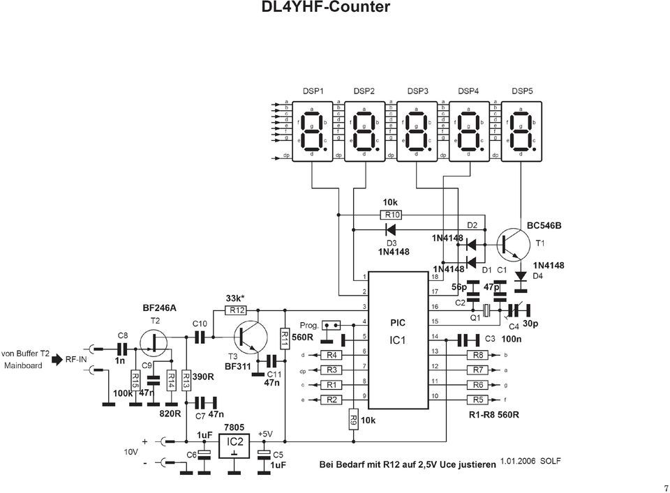
2 Frequency Counter based on PIC with minimal-hardware von Wolfgang "Wolf" Büscher, DL4YHF Letzte Aktualisierung: The heart of the circuit is an 18 pin PIC 16F628 Microcontroller. With the software of Wolf we get an universal frequency counter. * Frequenz range 1 Hz to 50 MHz (Most kits work up to 60 MHz which is pretty high above the specification of the Processor). * Automatic range switch with different gate timimg * pragrammable offset for superhet receivers (IF shift), either addition or subtraction possible * Preprogrammed Offsets for common IF e.g MHz for "Miss Mosquita" Transceiver * Opional power save mode: power of after 15 s with no variation of the frequency. The actual firmware can be downloaded from Wolfs hompage. If you want to add something, you may use the assembler file which is also available there. The QRPproject kit contains a preprogrammed PIC Description of the Function After power on the counter shows " " to test all segments of the Display for a short time. In the next step the actual measured frequency will be shown. * flashing decima point: = Display in khz; * steady decimal point = Display in MHz. The range is automatically switched to give maximum resolution and minimum Gate time: Range Display Gate decimal point khz X.XXX 1 second flashing khz XX.XX(X) 0.5 second flashing khz XXX.X(X) 0.25 second flashing MHz X.XXX(X) 0.25 second steady MHz XX.XX(X) 0.25 second steady 2 Programming mode During 'Programming mode' you can progtramm an frequency offset and the power save mode. To programm the controller you must attach a closing swith to pin 4 of the microprocessor. Programming mode flow chart The program flow chart on the left shows how to enter programming mode, how to select a menu, and how to execute the associated function. To enter programming mode, press and hold the programming key (or connect pin 4 and 5 of the PIC with a small screwdriver), until the PIC shows ProG on the LED display. Then release the key. You are now in the first menu of the programming mode. To select the next menu, press the key for a short time (less than a second). To execute the selected function, press the key for a longer time (more than a second). The menu functions are : Quit : Aborts programming mode without changing anything. Add : Saves the previously measured frequency permanently, so it will be added in future. Sub : Saves the previously measured frequency permanently, so it will be subtracted in future. Zero : Sets the frequency offset to zero, so the display will show the measured frequency without offset. The previously programmed offset will be lost. Table : Allows you to select a predefined offset value from a table. The table itself is also located in the PIC s data EEPROM, so you may find different values in it. When skipping through the table, the frequencies are shown in numeric form, like (khz),

3 (MHz), (MHz), (MHz). After selecting an entry (long keypress), you will be taken back to the main menu to select Add or Subtract. PSave / NoPSV : turns the power-saving on/off. In power-saving mode, the display is turned off after 15 seconds of no significant change in frequency, and on again as soon as the frequency changes by more than a few dozen Hertz (in the 3..4 MHz measuring range) RX Frequency = Oscillatorfrequency - IF =14,314-4,194 =10120 If you want not the see the 10 MHz use 14,194 instead of 4,194. The will be shown as Addieren oder Subtrahieren von Frequenzen If the counter is used in an superhet receiver (or transmitter) you must add or substract the IF frequency (dependig on up or down conversion. In the programming (Setup) Section you can choose a common IF frequency or if your IF cannot be found in the table you can programm any IF. The following example shows how to programm a tranceiver like our Miss Mosquita with 4MHz IF Quartzfilter (Oscillator of TX at 3,999 MHz) 1. counter power on 2. close programming- switch shortly until display shows "PROG" 3. Release the switch 4. Close and open the switch until you see "TABLE" in the display 5. Close and open the switch until you see "TABLE" flashing, release the switch. You are now in a sub menue which shows all preprogrammes offsets. 6. Close and open the switch until the wanted IF (3.999) is shown in the display. 7. Close switch until "3.999" is flashing, release the switch 8. Now you should see "Add" in the display. If not close and release switch until you see "Add" 9. Close switch untill you see "Add" flashing, release switch Ready. The IF of MHz has been written to the EEProm now, it will be added to the actually measured VFO frequency. Little bit mor tricky is the calculation for the 10MHz and above. Because we have only 5 digits it makes sense not to show the 10 and 1 MHz digits. If we use a negative offset, the display will only show the 1 MHz digit but the 100Hz digit can still be seen. Example for a 30 Meter Transceiver with VCXO: 3
 you must add or substract the IF frequency (dependig on up or down conversion.")
4 Assembling Use the PCB as shown in the picture to get some orientation. Don t install the connectors now, this will be done later on. Solder Resistor R9 first. You see R9 mirrored inside the outline for the microprocessor IC1 that means it must be mounted at the bottom side (solder side of the PCB. [ ] R9 10k Mount at bottom side, solder at part side. cut the remaining pins short above the solder joint. Now mound other parts to the part side and solder at the bottom side. Start lin the lower left corner. Try to solder each part as low as possible above the PCB. If they are mounted on long legs you will get run into trouble when mounting the Display board. [ ] D4 1N1448 The diode has a band at the cathode side. Orientation of the band on the PCB as shown in the drawing [ ] D2 1N4148 -upright If a Diode is mounted upright, there is a circle as an outlin on the PCB. Mount the diode with its body inside the circle, the band (cathode) agt the upper side (see picture left! [ ] D1 1N4148 upright as D2 4 [ ] D3 1N4148 upright as D2/D3 [ ] R10 10k, upright [ ] R11 560R [ ] C11 47 nf (473) [ ] C10 10 nf (103) [ ] R12 33k [ ] C9 47nF (473) [ ] R13 390R [ ] R14 820R [ ] C7 47nF [ ] C6 1uF Elko, ATTENTION, polarized. Long leg = PLUS [ ] C5 1uF Elko, ATTENTION, polarized. Long leg = PLUS [ ] C8 1nF (102) [ ] R15 100k [ ] C2 56pF [ ] Q1 20 MHz Quartz.Mount the Quartz with a abt 1mm distance between its body and the PCB to avoid a short by solder under it. [ ] C3 100nF (104) [ ] C1 47pF (47p, 47j) [ ] C4 Foil Trimmcapacitor 30pF Now the socket for the PIC Take care to mount it exactly as shown in the picture. The GAP at one of the small sides must look to the upper edge of the PCB. They will connect the display PCB to the counter PCB. Best way to mount and solder them is to assemble both PCBs complete with the connectors [ ] Socket IC1 The following female connectors are mounted on the solder side of the PCB Best way to do is to mount the complete assembly first without soldering. Check if all connectors are absolutely perpendicular. If so, solder them Use the female connectors for the counter PCB and the male connectors for the Display PCB Solder one PIN, check again and if it looks good, solder all Schnittzeichnung, Bauteile nach unten,von der Breitseite gesehen IC1 2x4 Verbinder weiblich

5 remaining PINs. Solder at the parts side of counter PCB: [ ] Connector 5,4,3,2,1 (female) [ ] Connector D,DP,C.E (female) [ ] Connector F,G,A,B (female) Now the other connectors to the outer world. They are mounted on the parts side and soldered on the solder side. [ ] Wire plus/minus (red/black) as conections to power (+6V bis +12V) at Ub [ ] Koaxcable or a pair of twisted wire at RF-in (later connection to VFO, Local Oszillator) [ ] Programm Switch at PROG Remaining parts are Semiconductors. Some of them, especially the PIC are ESD sensiticve. Discharge yourself by tapping your hand to a blank ground plate or better, use ur ESD sefety equipment. [ ] T1 BC546B [ ] T2 BF2546A [ ] T3 BF311 [ ] IC2 = 7805 (TO220 housing). Now put the PIC into the socket. Attention: the Gap or Pin 1 marker must look to the upper edge of the PCB / gap in the socket. [ ] PIC 16F628 OK, the counter is ready, now do the Diplay unit. This are only a few parts. In this Version, we call it the Mini Display Version the Displayboard is not mounted as a sandvich directly to the xounter board but it is connected by a couple of wires. This gives the freedom to mount the counter itself somwhere in the rig saving a lot of space at the frontplate. To make the Display design even smaller, we replaced the standard resistors by small SMT resistors. Don t be afraid if you never before handled SMT, this SMT resistors are easy to solder if you know the trick. Place the PCB in front of you so that you can see the rectangular solder pads as shown in the picture in the lower left corner. Solder one of the two opposite pads of each resistor using 0,5mm solder. There should be a half sphere on the pad after soldering. Now take the resistor with a tweezer, press it down to the PCB and aginst the half sphere. Touch the solder halsphere with your solder iron tip. In the moment the solder is melting, the resistor will move forward. Retrace the iron tip and bingo, on side of the resistor has been soldered perfectly. Solder the other side the normal way. Do this with all 8 resistors. [ ] R1 560R [ ] R2 560R [ ] R3 560R [ ] R4 560R [ ] R5 560R [ ] R6 560R [ ] R7 560R [ ] R8 560R Now the 5 Seven Segment Display Chips. They are soldered on the other side of the PCB. Please install them upright with the decimal point at the right place. Look at the Picture above to see how they must be installed. Press each Display firmly agaist the PCB and solder 1 pin at a corner first. Check if it is realy sitting flat on the PCB and solder a pin diaginal opposite. Check again if the display is flat on the PCB. If not, reheat and press the display down to the PCB. If it is ok, solder all remaining PINs. Same procedure for all 5 Displays. [ ] DSP1 5
![[ ] Wire plus/minus (red/black) as conections to power (+6V bis +12V) at Ub [ ] Koaxcable or a pair of twisted wire at RF-in (later connection to VFO, Local Oszillator) [ ] Programm Switch at PROG](/docs-images/46/21330456/images/page_5.jpg "Remaining parts are Semiconductors. Some of them, especially the PIC are ESD sensiticve. Discharge yourself by tapping your hand to a blank ground plate or better, use ur ESD sefety equipment.")
6 [ ] DSP2 [ ] DSP3 [ ] DSP4 [ ] DSP5 Thats all. Connect the Display with the counter boards by thin wires. The length of the wires is not that critical, but take care to connect the corresponding ports: A to A, E to E, DSP 1 to DSP1. If you now connect Power to the red(black UB line and any signal between 1 and 50 MHz to the RF line (coax or twisted pair of wire) you should see measured frequency now. If you use a Receiver / Transceiver as signal source, you will see the local Oscillator frequency. To see the TX/RX frequency you mustr add or subtract the IF frequency as described in the programming section of this manual. Partlist D1 1N4148 D2 1N4148 D3 1N4148 D4 1N4148 C1 47pF (47p, 47j) C2 56pF C3 100nF (104) C4 Foiltrimmcapacitor 30pF red 2 pin spacing 5mm C5 1uF Eléctrolytic cap C6 1uF Electrolytic cap C7 47nF C8 1nF (102) C9 47nF (473) C10 10 nf (103) C11 47 nf (473) Q1 20 MHz Quartz T1 BC546B T2 BF2546A T3 BF311 IC1 PIC 16F628-20P programmed (Attention, extrem ESD sensitive) IC TO220 Housing Socket 18 pin for IC1 (PIC) 7 Segment Display (5) pushbutton switch R1 560R 0805 SMT R2 560R 0805 SMT R3 560R 0805 SMT R4 560R 0805 SMT R5 560R 0805 SMT R6 560R 0805 SMT R7 560R 0805 SMT R8 560R 0805 SMT R9 10k R10 10k R11 560R R12 33k R13 390R R14 820R R15 100k 6

7 7
8 8

DL-QRP-AG Universal Frequency Display for QRP equipment
 DL-QRP-AG Universal Frequency Display for QRP equipment QRPproject Motzener Straße 36-38 12277 Berlin http://www.qrpproject.de Telefon: +49(30) 85 96 13 23 e-mail: support@qrpproject.de Handbucherstellung:
DL-QRP-AG Lambda/2 no Counterpoise: Fuchs Antenna matching unit
 DL-QRP-AG Lambda/2 no Counterpoise: Fuchs Antenna matching unit QRPproject Molchstr. 15 12524 Berlin http://www.qrpproject.de Telefon: +49(30) 85 96 13 23 e-mail: support@qrpproject.de Handbucherstellung:
RS232/DB9 An RS232 to TTL Level Converter
 RS232/DB9 An RS232 to TTL Level Converter The RS232/DB9 is designed to convert TTL level signals into RS232 level signals. This cable allows you to connect a TTL level device, such as the serial port on
Modifying the Yaesu FT-847 External 22.625 MHz Reference Input
 Modifying the Yaesu FT-847 External 22.625 MHz Reference Input David Smith VK3HZ Introduction This document describes the modification of an FT-847 to allow an external 22.625 MHz Reference oscillator
DDS VFO CONSTRUCTION MANUAL. DDS VFO Construction Manual Issue 1 Page 1
 DDS VFO CONSTRUCTION MANUAL DDS VFO Construction Manual Issue 1 Page 1 Important Please read before starting assembly STATIC PRECAUTION The DDS VFO kit contains the following components which can be damaged
A PIC16F628 controlled FLL (Frequency Locked Loop) VFO for HF
 VFO for HF") Abstract A PI6F628 controlled FLL (Frequency Locked Loop) VFO for HF It is described a device which joins in a single microprocessor a digital programmable frequency meter and a control logic capable to
Abstract A PI6F628 controlled FLL (Frequency Locked Loop) VFO for HF It is described a device which joins in a single microprocessor a digital programmable frequency meter and a control logic capable to
A CW QRP Transceiver for 20 m band. How it works I'll describe individually the three boards and the relative tuning devices.
 A CW QRP Transceiver for 20 m band The little QRP presented in this article may be built in a gradual manner, in fact it is divided in two main modules (plus VFO), you may also complete only a single part
K128. USB PICmicro Programmer. DIY Electronics (HK) Ltd PO Box 88458, Sham Shui Po, Hong Kong. http://www.kitsrus.com mailto: peter@kitsrus.
 Ltd PO Box 88458, Sham Shui Po, Hong Kong. http://www.kitsrus.com mailto: peter@kitsrus.") K128 USB PICmicro Programmer DIY Electronics (HK) Ltd PO Box 88458, Sham Shui Po, Hong Kong http://www.kitsrus.com mailto: peter@kitsrus.com Last Modified March 31 2003 Board Construction The board is
K128 USB PICmicro Programmer DIY Electronics (HK) Ltd PO Box 88458, Sham Shui Po, Hong Kong http://www.kitsrus.com mailto: peter@kitsrus.com Last Modified March 31 2003 Board Construction The board is
Joule Thief 3.0 Kit. June 2012, Rev 1 1 http://www.easternvoltageresearch.com Joule Thief 3.0
 Kit Instruction Manual Eastern Voltage Research, LLC June 2012, Rev 1 1 http://www.easternvoltageresearch.com HIGH BRIGHTNESS LED THIS KIT USES A 1W CREE, HIGH BRIGHTNESS LED. DO NOT STARE AT THIS (OR
POCKET AUDIO GENERATOR K8065
 POCKET AUDIO GENERATOR K8065 Great little gadget for service repair, testing, education, etc... ILLUSTRATED ASSEMBLY MANUAL H8065IP-1 VELLEMAN NV Legen Heirweg 33 9890 Gavere Belgium Europe www.velleman.be
PC FUNCTION GENERATOR
 PC FUNCTION GENERATOR Create standard signal waves like e.g. sine, triangle and rectangle are available; other sine waves can be easily created with integrated software. Total solder points: 954 Difficulty
TEECES DOME LIGHTING SYSTEMS
 This lighting system was designed by John V (Teeces) to be a simple, customizable, expandable and affordable solution for dome lighting. An Arduino micro-controller is used to tell LED driver chips which
K8025 VIDEO PATTERN GENERATOR. Check the picture quality of your monitor or TV, ideal for adjustment or troubleshooting.
 K8025 ILLUSTRATED ASSEMBLY MANUAL H8025IP 1 VIDEO PATTERN GENERATOR Check the picture quality of your monitor or TV, ideal for adjustment or troubleshooting. Forum Participate our Velleman Projects Forum
AXE114S BINARY CLOCK. revolution Revolution Education Ltd. Email: info@rev-ed.co.uk Web: www.rev-ed.co.uk Version 1.1 12/09/08 AXE114.PMD.
 AXE114S BINARY CLOCK Features: The PICAXE binary clock kit tells the time by lighting up blue LEDs in a binary pattern. This is a useful tool for teaching students binary code or simply just confusing/
DIGITAL PC SCOPE. Total solder points: 625 Difficulty level: beginner 1 2 3 4 5 advanced K8031 ILLUSTRATED ASSEMBLY MANUAL
 DIGITAL PC SCOPE Digital storage oscilloscoop, using a computer and its monitor to display waveforms. All standard oscilloscope functions are available in the Windows program supplied. Total solder points:
DUAL ELECTRONIC DICE K3400
 DUAL ELECTRONIC DICE K3400 Cheating is no longer possible! ILLUSTRATED ASSEMBLY MANUAL H3400IP-1 VELLEMAN NV Legen Heirweg 33 9890 Gavere Belgium Europe www.velleman.be www.velleman-kit.com Features &
K6002 TEMPERATURE CONTROLLER. Specifications
 Total solder points: 169 + 99 + 67 Difficulty level: beginner 1 2 3 4 5 advanced TEMPERATURE CONTROLLER K6002 Unlike a normal thermostat, this kit has two outputs, one for "high" alarm and one for "low"
Total solder points: 167 Difficulty level: beginner 1 2 3 4 5 advanced DMX CONTROLLED RELAY K8072 ILLUSTRATED ASSEMBLY MANUAL
 Total solder points: 167 Difficulty level: beginner 1 2 3 4 5 advanced DMX CONTROLLED RELAY K8072 Control a relay by means of the wellknown DMX512 protocol. ILLUSTRATED ASSEMBLY MANUAL H8072IP-1 Features
K8068 BUS DIMMER FOR HOME MODULAR LIGHT SYSTEM ILLUSTRATED ASSEMBLY MANUAL H8068IP-1
 Total solder points: 74 Difficulty level: beginner 1 2 3 4 5 advanced BUS DIMMER FOR HOME MODULAR LIGHT SYSTEM K8068 PLUG - IN module for use with home modular lights system K8006. For electronic transformers!
Youkits TJ2B 2016 SSB CW HF TRANSCEIVER OPERATION GUIDE
 Youkits TJ2B 2016 SSB CW HF TRANSCEIVER OPERATION GUIDE TJ2B is a high-performance QRP portable multi-band SSB/CW transceiver, used with DDS as LO, offering wide frequency coverage and fine tuning rate.
Frequency counter with a PIC and minimum hardware
 1 di 9 02/06/2008 16.28 Frequency counter with a PIC and minimum hardware by Wolfgang "Wolf" Büscher, DL4YHF Last updated: 2006-05-15. to main site This document describes the construction of small frequency
Assembly Instructions: Shortwave Radio Kit
 Assembly Instructions: Shortwave Radio Kit MTM Scientific, Inc P.O. Box 522 Clinton, MI 49236 U.S.A Introduction Fig 1: The assembled Shortwave Radio Kit The SHORTWAVE RADIO KIT (#SWRAD) from MTM Scientific
7-SEGMENT DIGITAL CLOCK
 57mm 7-SEGMENT DIGITAL CLOCK Large 57mm clock & temperature display with extra unique feature Total solder points: 263 Difficulty level: beginner 1 2 3 4 5 advanced K8089 ILLUSTRATED ASSEMBLY MANUAL H8089IP-1
WHO ANSWERED FIRST? FIND OUT WITH THIS QUIZ BUZZER KIT
 WHO ANSWERED FIRST? FIND OUT WITH THIS QUIZ BUZZER KIT BUILD INSTRUCTIONS Before you put any components in the board or pick up the soldering iron, just take a look at the Printed Circuit Board (PCB).
ECEN 1400, Introduction to Analog and Digital Electronics
 ECEN 1400, Introduction to Analog and Digital Electronics Lab 4: Power supply 1 INTRODUCTION This lab will span two lab periods. In this lab, you will create the power supply that transforms the AC wall
Fig.1. A basic inductance and capacitance. (CR) oscillator.
 oscillator.") Constructional Project PIC LCF METER JOHN BECKER Simple monitoring of inductance, capacitance and frequency values HIS simple PIC-based unit was designed to measure and display the Tvalues of inductors
Constructional Project PIC LCF METER JOHN BECKER Simple monitoring of inductance, capacitance and frequency values HIS simple PIC-based unit was designed to measure and display the Tvalues of inductors
Total solder points: 248 Difficulty level: beginner 1 2 3 4 5 advanced. 15 Channel infrared receiver K8050 ILLUSTRATED ASSEMBLY MANUAL
 Total solder points: 48 Difficulty level: beginner 4 5 advanced 5 Channel infrared receiver K8050 IR-Remote control transmitters allow you to control 5 opencollector contacts ILLUSTRATED ASSEMBLY MANUAL
Total solder points: 129 Difficulty level: beginner 1 2 3 4 5 advanced LIQUID LEVEL CONTROLLER K2639 ILLUSTRATED ASSEMBLY MANUAL H2639IP-1
 Total solder points: 129 Difficulty level: beginner 1 2 3 4 5 advanced LIQUID LEVEL CONTROLLER K2639 Forgotten to turn off the tap, leaking washing machines,... Prevention is better than cure. So use this
AUTOMATIC CALL RECORDER JAMECO PART NO. 2163735
 AUTOMATIC CALL RECORDER JAMECO PART NO. 2163735 Experience Level: Intermediate Time Required: 1-2 Hours This project automatically records phone calls. The program, along with the adapter records each
Homebuilt HF Radios for Use Underground Paul R. Jorgenson KE7HR
 Homebuilt HF Radios for Use Underground Paul R. Jorgenson KE7HR With the good success in using Amateur Band HF radio for underground communications, I started looking for cheaper alternatives to the $500+
PolyBot Board. User's Guide V1.11 9/20/08
 PolyBot Board User's Guide V1.11 9/20/08 PolyBot Board v1.1 16 pin LCD connector 4-pin SPI port (can be used as digital I/O) 10 Analog inputs +5V GND GND JP_PWR 3-pin logic power jumper (short top 2 pins
VOLUME AND TONE CONTROL - PREAMPLIFIER K8084
 H8084IP-1 VOLUME AND TONE CONTROL - PREAMPLIFIER K8084 When using one of our amplifiers (big or small), you always need a volume control and preferably also a tone control Features & specifications When
Alpha 10 SERVICE MANUAL. Downloaded from www.cbradio.nl. MAX 10 Meter Amateur Transceiver AM/FM/CW/SSB 6 BAND PROGRAMMABLE MODEL AM-1000.
 Alpha 10 MAX 10 Meter Amateur Transceiver MODEL AM-1000 AM/FM/CW/SSB 6 BAND PROGRAMMABLE SERVICE MANUAL Downloaded from www.cbradio.nl Cover Page LOUDER TALKBACK MOD Alpha 10 Max - Model AM-1000 4.7K Resistor
Technical Details and Schematic: A 1200-Baud APRS / Packet Digipeater
 Fox Delta Amateur Radio Projects & Kits FoxDigi Technical Details and Schematic: A 1200-Baud APRS / Packet Digipeater Rev: 141208 Completed FoxDigi: Project Introduction: FoxDigi is a PIC16F88 based 1200-Baud
Total solder points: 115 Difficulty level: beginner 1 2 3 4 5 advanced 4 CHANNEL RUNNING LIGHT K8032 ILLUSTRATED ASSEMBLY MANUAL
 Total solder points: 115 Difficulty level: beginner 1 2 3 4 5 advanced 4 CHANNEL RUNNING LIGHT K8032 Ideal for creating disco light effects, light speed adjustable. Suited for inductive loads. ILLUSTRATED
G4HUP Panoramic Adaptor Installation FT847
 G4HUP Panoramic Adaptor Installation FT847 These instruction cover installation of the PAT board in the 1st IF of the FT847 45.705MHz this gives access to all receiver options on the main receiver. A a
400W MONO/STEREO AMPLIFIER
 400W MONO/STEREO AMPLIFIER Universal, robust and compact are the words to describe this amplifier. Total solder points: 264 Difficulty level: beginner 1 2 3 4 5 advanced K4005B ILLUSTRATED ASSEMBLY MANUAL
Assembly and User Guide
 1 Amp Adjustable Electronic Load 30V Max, 1 Amp, 20 Watts Powered by: 9V Battery Assembly and User Guide Pico Load is a convenient constant current load for testing batteries and power supplies. The digital
Total solder points: 205 Difficulty level: beginner 1 2 3 4 5 advanced UNIVERSAL BATTERY CHARGER / DISCHARGER K7300 ILLUSTRATED ASSEMBLY MANUAL
 Total solder points: 205 Difficulty level: beginner 1 2 3 4 5 advanced UNIVERSAL BATTERY CHARGER / DISCHARGER K7300 Automatic (dis)charging of both NiCd and NiMH batteries. ILLUSTRATED ASSEMBLY MANUAL
SMD Soldering Guide by Infidigm
 SMD Soldering Guide by Infidigm Purpose The purpose of this guide is to introduce SMD (Surface Mount Device) hand soldering. The guide is organized into different methods. Each method is used specifically
GUITAR PREAMPLIFIER WITH HEADPHONE OUTPUT K4102
 H4102IP-1 GUITAR PREAMPLIFIER WITH HEADPHONE OUTPUT K4102 Practice the guitar without disturbing others. Features & Specifications Features: An electric guitar cannot be connected to just any amplifier
The $25 Son of a cheap timer This is not suitable for a beginner. You must have soldering skills in order to build this kit.
 The $25 Son of a cheap timer This is not suitable for a beginner. You must have soldering skills in order to build this kit. Micro Wizard has been manufacturing Pinewood Derby timers for over 10 years.
RS232C < - > RS485 CONVERTER S MANUAL. Model: LD15U. Phone: 91-79-4002 4896 / 97 / 98 (M) 0-98253-50221 www.interfaceproducts.info
 0-98253-50221 www.interfaceproducts.info") RS232C < - > RS485 CONVERTER S MANUAL Model: LD15U INTRODUCTION Milestone s model LD-15U is a RS232 to RS 485 converter is designed for highspeed data transmission between computer system and or peripherals
RS232C < - > RS485 CONVERTER S MANUAL Model: LD15U INTRODUCTION Milestone s model LD-15U is a RS232 to RS 485 converter is designed for highspeed data transmission between computer system and or peripherals
200W DISCRETE POWER AMPLIFIER K8060
 H8060IP-1 200W DISCRETE POWER AMPLIFIER K8060 Ideal for active speaker system or subwoofer, guitar amp, home theatre systems, instrument amp, etc. Features & Specifications Specifications: Excellent value
!Operation:!1. Connect an external power source to J1 (+ and - IN terminals). The
. The") The CB500 Electronic Circuit Breaker is an resettable circuit breaker (fuse) that disconnects power when the trip setting is exceeded. There are 4 trip settings that can easily be changed and set during
The CB500 Electronic Circuit Breaker is an resettable circuit breaker (fuse) that disconnects power when the trip setting is exceeded. There are 4 trip settings that can easily be changed and set during
Total solder points: 57 Difficulty level: beginner 1 2 3 4 5 advanced 3 TO 30VDC / 3A POWER SUPPLY K7203 ILLUSTRATED ASSEMBLY MANUAL H7203IP-1
 Total solder points: 57 Difficulty level: beginner 1 2 3 4 5 advanced 3 TO 30VDC / 3A POWER SUPPLY K7203 A power supply for all our kits, based on a stabilised DC voltage of 30V. ILLUSTRATED ASSEMBLY MANUAL
K4401 SOUND GENERATOR. them at the touch of a button. Specifications
 SOUND GENERATOR K4401 Sound effects, tunes, sirens... 10 of them at the touch of a button. Specifications Loudspeakers output : 8 ohm/1w Line output : 1VRms. Power supply : 8 10VDC (9v battery). Max. current
Nixie Clock Universal Kit V1.08. Assembly and Operation. Software Version 6.3 Revision 11. 11. 2012
 Nixie Clock Universal Kit V1.08 Assembly and Operation Software Version 6.3 Revision 11. 11. 2012 This document is copyrighted. No parts of this documentation may be used commercially. Nixie Clock Kit
Ocean Controls RC Servo Motor Controller
 Ocean Controls RC Servo Motor Controller RC Servo Motors: RC Servo motors are used in radio-controlled model cars and planes, robotics, special effects, test equipment and industrial automation. At the
PGA103+ Low noise, high dynamic range preamp for VHF and UHF
 PGA103+ Low noise, high dynamic range preamp for VHF and UHF By Sam Jewell, G4DDK and Kent Britain, WA5VJB Introduction This paper describes a low noise, high dynamic range VHF/UHF preamp that uses the
MAINS VOLTAGE DETECTOR K7101
 With this device wires can be very easily checked for mains voltage. H7101IP-1 MAINS VOLTAGE DETECTOR K7101 VELLEMAN NV Legen Heirweg 33 9890 Gavere Belgium Europe www.velleman.be www.velleman-kit.com
Controlling a Dot Matrix LED Display with a Microcontroller
 Controlling a Dot Matrix LED Display with a Microcontroller By Matt Stabile and programming will be explained in general terms as well to allow for adaptation to any comparable microcontroller or LED matrix.
Tutorials Drawing a 555 timer circuit
 Step 1 of 10: Introduction This tutorial shows you how to make an electronic circuit using Livewire and PCB Wizard 3. You should follow this tutorial to learn the basic skills you will need to use Livewire
THE R551N RECEIVER FAQ FAULT FINDING THE REDIFON COMMUNICATIONS RECEIVER R551N. Date: October 10th 1995 by: Jan Verduyn G5BBL
 THE R551N RECEIVER FAQ FAULT FINDING THE REDIFON COMMUNICATIONS RECEIVER R551N Introduction: Date: October 10th 1995 by: Jan Verduyn G5BBL Recently a number of Redifon R551N receivers have appeared on
- 35mA Standby, 60-100mA Speaking. - 30 pre-defined phrases with up to 1925 total characters.
 Contents: 1) SPE030 speech synthesizer module 2) Programming adapter kit (pcb, 2 connectors, battery clip) Also required (for programming) : 4.5V battery pack AXE026 PICAXE download cable Specification:
Electronic Rotary Table Divider V2.1 Construction
 Electronic Rotary Table Divider V2.1 Construction 2006,2013 Steve Ward (steve@worldofward.com) Legal: All documents, code, schematics, firmware etc are offered as an aid to the experienced constructor
revolution Revolution Education Ltd. Email: info@rev-ed.co.uk Web: www.rev-ed.co.uk Vesrion 2.128/08/02 PICLOCK.P65 SELF -ASSEMBL Order Codes:
 PIC IC L -A IC LOCK SELF ELF-A -ASSEMBL SSEMBLY KIT IT IT (V2) Order Codes: CHI008 PIC Lock Self-Assembly Kit 1 2 3 4 5 6 7 8 9 0 # SW + OUT + 6V 0V Ú LK1 LK2 Features 12 key telephone style keypad bicolour
FLYPORT Wi-Fi 802.11G
 FLYPORT Wi-Fi 802.11G System on module 802.11g WIFI - Infrastructure mode - softap mode - Ad hoc mode Microchip PIC 24F 16 bit processor Microchip MRF24WG0MA/MB - Native WiFi 802.11g transceiver - PCB
Martin County Amateur Radio Association. Nightfire Kits 1 LED Torch Kit 270016. Contents. Description
 Nightfire Kits 1 LED Torch Kit 270016 1 Contents Nightfire Kits LED Torch Kit 270016... 1 Description... 1 Safety and Assembly of the kit... 6 Required and Useful Tools... 7 Assembly... 8 Checkout and
The new Velleman Projects catalogue is now available. Download your copy here: www.vellemanprojects.eu
 The new Velleman Projects catalogue is now available. Download your copy here: www.vellemanprojects.eu Modifications and typographical errors reserved - Velleman nv. H8098 IP 2 (rev.1.0) Velleman NV, Legen
Build A Video Switcher. Reprinted with permission from Electronics Now Magazine September 1997 issue
 Build A Video Switcher Reprinted with permission from Electronics Now Magazine September 1997 issue Copyright Gernsback Publications, Inc.,1997 BUILD A VIDEO SWITCHER FRANK MONTEGARI Watch several cameras
Cumbria Designs T-1. SSB/CW Filter kit (4.9152MHz) User Manual
 User Manual") Cumbria Designs T-1 SSB/CW Filter kit (4.9152MHz) User Manual CONTENTS 1 INTRODUCTION 2 2 CIRCUIT DESCRIPTION 2 3 ASSEMBLY 2 4 TESTING 4 The Steading Stainton PENRITH Cumbria CA11 0ES UK 1 Introduction
Cumbria Designs T-1 SSB/CW Filter kit (4.9152MHz) User Manual CONTENTS 1 INTRODUCTION 2 2 CIRCUIT DESCRIPTION 2 3 ASSEMBLY 2 4 TESTING 4 The Steading Stainton PENRITH Cumbria CA11 0ES UK 1 Introduction
Wireless Security Camera
 Wireless Security Camera Technical Manual 12/14/2001 Table of Contents Page 1.Overview 3 2. Camera Side 4 1.Camera 5 2. Motion Sensor 5 3. PIC 5 4. Transmitter 5 5. Power 6 3. Computer Side 7 1.Receiver
The basic set up for your K2 to run PSK31 By Glenn Maclean WA7SPY
 The basic set up for your K2 to run PSK31 By Glenn Maclean WA7SPY I am by no means an expert on PSK31. This article is intended to help someone get on PSK31 with a K2. These are the things I did to get
PCAN-MicroMod Universal I/O Module with CAN Interface. User Manual. Document version 2.1.0 (2014-01-16)
") PCAN-MicroMod Universal I/O Module with CAN Interface User Manual Document version 2.1.0 (2014-01-16) Products taken into account Product Name Part number Model PCAN-MicroMod IPEH-002080 with firmware
PCAN-MicroMod Universal I/O Module with CAN Interface User Manual Document version 2.1.0 (2014-01-16) Products taken into account Product Name Part number Model PCAN-MicroMod IPEH-002080 with firmware
The G-QRP Club. The Limerick Sudden 40m Receiver Kit
 The G-QRP Club The Limerick Sudden 40m Receiver Kit Circuit design George Dobbs G3RJV PCB design Rex Harper W1REX Kit parts spec and purchase Graham Firth G3MFJ Manual G3RJV and G3MFJ soku=j~ó=omnp= 1
Kit 106. 50 Watt Audio Amplifier
 Kit 106 50 Watt Audio Amplifier T his kit is based on an amazing IC amplifier module from ST Electronics, the TDA7294 It is intended for use as a high quality audio class AB amplifier in hi-fi applications
A simple RF/Microwave frequency counter
 Matjaz Vidmar, S53MV A simple RF/Microwave frequency counter I decided to design a simple, easily reproducible counter around a PIC 16F876A. The basic counter range is extended to at least 180MHz using
Single Transistor FM Transmitter Design
 Single Transistor FM Transmitter Design In telecommunications, frequency modulation (FM) conveys information over a carrier wave by varying its frequency. FM is commonly used at VHF radio frequencies for
The Quadcopter Controller
 The Quadcopter Controller Table of Contents Introduction to the Quadcopter controller...2 Flight Configurations...2 Updating the Firmware...3 Mounting the Quadcopter controller in your Quadcopter...8 Quadcopter
POWERBLOCK - POWER AMPLIFIER
 POWERBLOCK - POWER AMPLIFIER This amplifier is an ideal set-up for active speaker use. Total solder points: 383 Difficulty level: beginner 1 2 3 4 5 advanced K8081 ILLUSTRATED ASSEMBLY MANUAL H8081IP-1
Total solder points: 85 Difficulty level: beginner 1 2 3 4 5 advanced MULTIFUNCTION RELAY SWITCH K8015 ILLUSTRATED ASSEMBLY MANUAL H8015IP-2
 Total solder points: 85 Difficulty level: beginner 1 2 3 4 5 advanced MULTIFUNCTION RELAY SWITCH K8015 14 Different functions including timers, switching, flashing, interval, random switching,... ILLUSTRATED
Controller for AD9850 DDS Modules Andy Talbot G4JNT 2012-12-06
 Controller for AD9850 DDS Modules Andy Talbot G4JNT 2012-12-06 Latest Comments. Construction notes and feedback from builders at the end The low cost ( 3) Chinese made modules available via Ebay contain
AUTOMATIC NIGHT LAMP WITH MORNING ALARM USING MICROPROCESSOR
 AUTOMATIC NIGHT LAMP WITH MORNING ALARM USING MICROPROCESSOR INTRODUCTION This Project "Automatic Night Lamp with Morning Alarm" was developed using Microprocessor. It is the Heart of the system. The sensors
Electronics and Soldering Notes
 Electronics and Soldering Notes The Tools You ll Need While there are literally one hundred tools for soldering, testing, and fixing electronic circuits, you only need a few to make robot. These tools
The Radio-Kits Digital SWR meter kit Construction and user manual
 The Radio-Kits Digital SWR meter kit Construction and user manual Author - Steve Drury G6ALU List of contents Section Page no. 1. Features and specifications 2 2. Introduction 2. Construction 4. General
Single Channel Loop Detector
 Single Channel Loop Detector Model - LD100 Series The LD100 is a single channel inductive loop detector designed for parking and access control applications. The detector is connected to an inductive loop
Bluetooth + USB 16 Servo Controller [RKI-1005 & RKI-1205]
![Bluetooth + USB 16 Servo Controller [RKI-1005 & RKI-1205]](/thumbs/40/21161302.jpg "Bluetooth + USB 16 Servo Controller [RKI-1005 & RKI-1205]") Bluetooth + USB 16 Servo Controller [RKI-1005 & RKI-1205] Users Manual Robokits India info@robokits.co.in http://www.robokitsworld.com Page 1 Bluetooth + USB 16 Servo Controller is used to control up to
Bluetooth + USB 16 Servo Controller [RKI-1005 & RKI-1205] Users Manual Robokits India info@robokits.co.in http://www.robokitsworld.com Page 1 Bluetooth + USB 16 Servo Controller is used to control up to
INTERNATIONAL ATOMIC ENERGY AGENCY INSTRUMENTATION UNIT SMD (SURFACE MOUNTED DEVICES) REPAIR S. WIERZBINSKI FEBRUARY 1999
 REPAIR S. WIERZBINSKI FEBRUARY 1999") (SURFACE MOUNTED DEVICES) REPAIR S. WIERZBINSKI FEBRUARY 1999 (SURFACE MOUNTED DEVICES) REPAIR 1 TABLE OF CONTENTS PAGE 1. INTRODUCTION 3 2. ADVANTAGES 4 3. LIMITATIONS 4 4. DIALECT 5 5. SIZES AND DIMENSIONS
(SURFACE MOUNTED DEVICES) REPAIR S. WIERZBINSKI FEBRUARY 1999 (SURFACE MOUNTED DEVICES) REPAIR 1 TABLE OF CONTENTS PAGE 1. INTRODUCTION 3 2. ADVANTAGES 4 3. LIMITATIONS 4 4. DIALECT 5 5. SIZES AND DIMENSIONS
RADIANT PLASMA 4700 Plasma Spark Generator
 RADIANT PLASMA 4700 Plasma Spark Generator Installation Guide / User Manual A S P A R K O F F R E S H A I R Aquapulser.com Contents 1 Introduction 2 1.1 About the Product....................................
Digital I/O: OUTPUT: Basic, Count, Count+, Smart+
 Digital I/O: OUTPUT: Basic, Count, Count+, Smart+ The digital I/O option port in the 4-Series provides us with 4 optically isolated inputs and 4 optically isolated outputs. All power is supplied externally.
The RSGB Centenary Receiver Project Construction Manual
 The RSGB Centenary Receiver Project Construction Manual Page 1 of 12 Introduction This project is intended for those new to radio construction. It is a fairly simple receiver for the 14MHz (20m) amateur
NC-12 Modbus Application
 NC-12 Modbus Application NC-12 1 Table of Contents 1 Table of Contents... 2 2 Glossary... 3 SCADA...3 3 NC-12 Modbus in general... 3 4 Entire system... 4 4.1 PFC to PC connection alternatives...4 4.1.1
XBee USB Adapter Board (#32400)
") Web Site: www.parallax.com Forums: forums.parallax.com Sales: sales@parallax.com Technical: support@parallax.com Office: (916) 624-8333 Fax: (916) 624-8003 Sales: (888) 512-1024 Tech Support: (888) 997-8267
Web Site: www.parallax.com Forums: forums.parallax.com Sales: sales@parallax.com Technical: support@parallax.com Office: (916) 624-8333 Fax: (916) 624-8003 Sales: (888) 512-1024 Tech Support: (888) 997-8267
MidiStream. UHF Wireless MIDI System Operating Manual
 MidiStream UHF Wireless MIDI System Operating Manual Introduction Congratulations on your purchase of the MidiStream UHF wireless MIDI system. The MidiStream system is very easy to use, but please take
Robot Board Sub-System Testing. Abstract. Introduction and Theory. Equipment. Procedures. EE 101 Spring 2006 Date: Lab Section # Lab #6
 EE 101 Spring 2006 Date: Lab Section # Lab #6 Name: Robot Board Sub-System Testing Partner: No Lab partners this time! Abstract The ECEbot robots have a printed circuit board (PCB) containing most of the
Product Information S N O. Portable VIP protection CCTV & Alarm System 2
 Product Information S N O Portable VIP protection CCTV & Alarm System 2 G O V E R N M E N T A L S E C U R I T Y S O L U T I VIP KIT Rapid Deployment VIP Protection Kit The VIP KIT has been designed to
Interfacing To Alphanumeric Displays
 Interfacing To Alphanumeric Displays To give directions or data values to users, many microprocessor-controlled instruments and machines need to display letters of the alphabet and numbers. In systems
Overnight Sensations Speaker Kit
 Overnight Sensations Speaker Kit Thank you for purchasing the Overnight Sensation cabinet kit. This speaker kit was precision cut using CNC machinery for the best possible fit and finish. With a little
Episode 126: Capacitance and the equation C =Q/V
 Episode 126: Capacitance and the equation C =Q/V Having established that there is charge on each capacitor plate, the next stage is to establish the relationship between charge and potential difference
MANUAL FOR RX700 LR and NR
 MANUAL FOR RX700 LR and NR 2013, November 11 Revision/ updates Date, updates, and person Revision 1.2 03-12-2013, By Patrick M Affected pages, ETC ALL Content Revision/ updates... 1 Preface... 2 Technical
K2570 UNIVERSAL POWER SUPPLY 5-14DC / 1A. The easy way to power your ILLUSTRATED ASSEMBLY MANUAL
 Total solder points: 18 Difficulty level: beginner 1 2 3 4 5 advanced UNIVERSAL POWER SUPPLY 5-14DC / 1A K2570 The easy way to power your projects. ILLUSTRATED ASSEMBLY MANUAL H2570IP-1 Features & Specifications
BUILDING INSTRUCTIONS
 etap2hw 38 mm I2C to LCD Interface BUILDING INSTRUCTIONS October 2013 P. Verbruggen Rev 1.01 15-Oct-13 Page 1 Table of Contents Chapter 1 General Information 1.1 ESD Precautions 1.2 Further Supplies 1.3
PGA103+ Low noise, high dynamic range preamp for VHF and UHF
 PGA103+ Low noise, high dynamic range preamp for VHF and UHF By Sam Jewell, G4DDK and Kent Britain, WA5VJB Introduction The PGA103+ from MCL achieves sub 0.5dB noise figure (NF) at 144MHz and better than
USER MANUAL MODEL 72-7480
 PATTERN GENERATOR Introduction Through the use of portable HDMI pattern generator MODEL 72-7480, you are able to use 48 timings and 34 patterns, and operate it continuously for 6~8 hours after the battery
PICAXE RF CONNECT KIT (AXE213)
") PICAXE RF CONNECT KIT (AXE213) Kit Contents: PCB AXE213 Transmitter & Receiver PCB Pair R1-3 10k resistor (brown black orange gold) R4-5 470 resistor (yellow violet brown gold) R6 22k resistor (red red
PICAXE RF CONNECT KIT (AXE213) Kit Contents: PCB AXE213 Transmitter & Receiver PCB Pair R1-3 10k resistor (brown black orange gold) R4-5 470 resistor (yellow violet brown gold) R6 22k resistor (red red
css Custom Silicon Solutions, Inc.
 css Custom Silicon Solutions, Inc. CSS555(C) CSS555/ PART DESCRIPTION The CSS555 is a micro-power version of the popular 555 Timer IC. It is pin-for-pin compatible with the standard 555 timer and features
Dashboard Digital Voltmeter
 Dashboard Digital Voltmeter...November, 2002 This project is helpful to anyone who drives an automobile. I had found this project at the local libary... in an old publication. I made it and it worked fine.
HC(S)08-System for Development and Training
08-System for Development and Training") SYSTECH J.Schnyder GmbH Schliefweg 30 CH-4106 Therwil Telefon 091 827 15 87 www.systech.ch HC(S)08-System for Development and Training Overview V 0.3 (Draft English) Contents Components... 3 Hardware...
SYSTECH J.Schnyder GmbH Schliefweg 30 CH-4106 Therwil Telefon 091 827 15 87 www.systech.ch HC(S)08-System for Development and Training Overview V 0.3 (Draft English) Contents Components... 3 Hardware...
SYMMETRIC 1A POWER SUPPLY K8042
 SYMMETRIC 1A POWER SUPPLY K8042 Low cost universal symmetric power supply ILLUSTRATED ASSEMBLY MANUAL H8042IP-1 Features & Specifications Features low cost universal symmetric power supply just add a suitable