Making Clock Wheel & Pinion Cutters
|
|
|
- Shavonne Daniels
- 9 years ago
- Views:
Transcription
1 Making Clock Wheel & Pinion Cutters When making hand made clocks or in repair work an odd size cutter is sometimes needed. Sometimes just one pinion is required and does not justify the cost of a commercial cutter. I have been making my own form relieved wheel cutters for years but shied away from making pinion cutters. Now that I am finished with commercial work I can try out all the ideas I have never had the time to try before. I have designed the making of the cutters with the owner of the small lathe in mind, there are many makes and models of small lathes on the market today and most of the parts of the tool can be modified to suit. Many years ago I made a fly cutter for making the reverse wheel pinion on a longcase clock. These pinions are made of brass but I pressed the cutter into service to do a trial run on a steel pinion. I wanted to use free cutting steel that I have in the workshop but I could not find it at the time (I ll find it later when looking for something else) and used a steel bolt instead. This was a blessing in disguise as the results of my efforts were most rewarding. The steel bolt was a nasty (sticky) sort of steel and not easy to machine with a fine finish. The pinion blank was set up in the pinion cutting machine and the cutter, centred. I took smaller bites of the pinion than if I was using a commercial cutter. I chose the most brutal and unforgiving way to cut the pinion with this carbon steel fly cutter, dry! What I was looking for was a distortion or leaning of the pinion leaf. I only cut 2 gashes to produce one test leaf but the results were most encouraging. The finish was not as good as a commercial cutter but there was no leaning of the leaf, which surprised me! I have read the articles by D Unwin and Duplex on this subject and thought I would combine some of the ideas of both into a system of making cutters. Unwin uses 4 tooth cutters and Duplex 12. I used the Duplex idea for making a drilling template and Unwins idea of a 4 tooth cutter. Both of the articles will make good wheel cutters but using a taper slide will ease the making of clock pinion cutters. I settled on a bore of 7mm as used in a lot of commercial cutters, and a diameter of 1 inch! I have tried to design the parts, so that no complicated set ups are needed. I could have used the 4 jaw chuck in some instances but realize that not everyone has this item. The threaded parts could be made on the lathe but ready made threaded bar is cheap to buy. For the small amount that is needed you can even use the thread from a couple of bolts. The device is designed around the Unimat lathe and has a 14mm x 1mm thread that screws direct to the lathe nose. This keeps the cutting forces nearer the bearings and of course you can modify the design to suit your own make of lathe. The first items to be made are the cutter blank holding tool and drilling template. I used an off cut of 2 x ½ inch brass for the holding tool but any metal will do and after turning the face true I formed a recess in the base to prevent rocking. Reverse in the chuck and true the top face. This has to have a good finish as the cutter blank sits on this surface. Drill

2 and tap 6mm and depending on the base thickness allow about 5/8 of the 6mm thread above the surface. Apply Loctite to the threads and run a nut up to the surface, tighten with a spanner or long reach socket, set aside for a few hours. When the Loctite has cured, chuck the base and turn the nut down to leave a 7mm diameter sleeve, clean the end of the 6mm thread. The drilling template is made from 3/16 thick steel plate or part off a 1 inch diameter slice on a larger lathe. Take a light cut to true the surfaces and take off the corners before parting. Having set the disk in the 3 jaw chuck I used my drilling spindle to spot 4 x 1/8 indexing holes on a radius of -375 and while in the chuck a 7mm hole was drilled and bored all at one setting. You could use the milling/drilling fixture for this. The disk was placed onto the base and spotted through with a 1/8 drill to show where to turn a groove for the drill to run into when in use. A 6mm brass/steel nut was made from hexagonal stock and while in the chuck a 7mm diameter shoulder was turned too a length of This will be used for centering the cutter blank onto the drilling template. The main body of the eccentric turning fixture is made from 1 inch diameter steel bar and it helps if you have access to a larger lathe for forming the 14x1mm thread. It can be done on the Unimat but it takes longer to do. If you have to use the Unimat I would suggest you hold the bar in the 4 jaw chuck. My piece of steel bar came from the scrap bin and has a smaller diameter at the front but a full 1 inch dia would be better, the length of the device is 1 ¼. Drill a 4-1mm Tommy bar hole on the side and screw the bar onto the lathe, true all the surfaces and remove from the lathe. Measure ¼ from the centre of the bar and drill and tap 6mm for a depth of 5/16. Loctite a 6mm stud into the device about 5/8 high. Place the drilling template onto the eccentric turning tool and use the nut with the 7mm shoulder. Rotate the disk until one of the holes is opposite the 6mm stud and drill a 1/8 hole for a locating peg, about 5/16 deep. Drill another hole about 3/32 right through, if the peg should shear off in use it can be removed with a punch from the inside. The peg should be just less than 1/8 high which will take the smallest thickness of cutter blank, secure with Loctite. A lot of suppliers sell gauge plate by the square inch and as the cutter blank will end up a sort of square shape with rounded edges it makes sense to preserve this shape. Set up the blank into the drilling template and drill 1/8 right through in all 4 places and remove from the tool. Give all the holes a slight counter sink on each side and rub down with emery or wet and dry paper to remove any burrs. Having set the cutter blank in the device I did a trial cut and the lathe was not happy with the intermittent cutting. I have read a great deal on this subject by other authors and they have always resorted to using a toothed belt for the final drive. This was another job that needed to be resolved and I had gathered the necessary parts over the years for such an occasion. My lathe was bought new in 1986 and the motor could not handle the demands of a commercial situation and

3 gave up within a year. Some of the newer lathes on the market are equipped with motors that provide a constant torque at slow revs and so no modifications might be necessary. Once the drive was sorted out it was back to making the cutters! I find that when doing these sorts of repetitive jobs that it is all too easy to go into auto pilot mode, so a good idea is to use stops on both axis of the lathe. My version for the Unimat has a two tier system for the cross and taper slide and a two way idea for a longitudinal stop. One of the suppliers that I have used for many years sells gauge plate in a 6 x 2 strip at a very reasonable price and this is enough to make 12 cutters. (It might be a good idea to make the cutter blanks in small batches as at this point they all start out the same.) Place a cutter blank into the eccentric turning tool and use a sharp hss turning tool to remove the unwanted metal, work to the stop or the dial gauge. What is needed is a square shaped blank with rounded edges. Remove the ordinary tool post and install the taper turning slide. The Unimat taper turning slide is not designed to be swung round this far and there are no setting marks on the cross slide but this is easy to remedy. If you don t want to mark your lathe just use a strip of masking tape on the cross slide. Set the slide parallel with the lathe axis and mark the tape with a pen at the 30deg mark and step round until you have enough marks to swing the taper slide round to 15deg either side. You might have to make an extension piece for the cross slide to avoid the hand wheels clashing. A -8 module, 8 leaf cutter was needed for an up date of a clock I made years ago and from the table of figures this turns out as, Tooth height = 86 thou, radius of form tool = 33 thou and cutter tip width =36 thou. The HSS lathe cutting tool is ground to a small parting tool shape and given a radius of I used my Metric drill gauge and used the 1-7mm hole to eye in the radius. I plan to make a grinding jig for this task. An 8 leaf pinion cutter has an inclusive angle of 30deg, so set the taper slide to 15deg and bring the cutting tool up to the side edge of the blank. Turn the lathe by hand and when the tool touches the blank, swing the blank out of the way and advance the tool the required amount. Set the depth stop or note the longitudinal dial reading. My blank was 200thou thick, so -036 from -2 = -164, div x 2 = Again, offer up the cutting tool to the face of the blank and advance the taper slide tool -086, (the tooth height) again set the depth stop or note the dial reading. Lock the cross slide or the settings will be lost! Retract the tool before starting the lathe and take small cuts until both slide stops prevent further cutting. I used cutting oil to ease the burden on the small lathe tool. When all 4 faces have been turned, remove from the tool and take off the burrs with 400 grit paper. Reverse the cutter blank and place in the tool, turn the remaining 4 faces. A jig is needed for making the radial faces of the cutter. A scrap piece of 1/8 brass plate is held in the lathe tool post. A 6mm stud was fitted and as before the

4 drilling template was used to locate a 1/8 diameter peg. Place the cutter blank into the holding jig using the nut with the 7mm shoulder. Install a slitting saw in the lathe and line the radial face of the cutter blank by eye, make a plunge cut of about 3/16 depth, I used neat cutting oil for this, applied with a small paint brush. After each saw cut the cutter was taken from the jig and any burrs were removed by rubbing on 400 grit paper. The saw blade was changed over for one of 1/8 thickness and used to remove the waste portions of the blank. This can be done with a hand held hacksaw and a file to remove the bulk of material. I have left a small portion of the original 4 dividing holes as an aid to future re-grinding of the cutters. Mark the cutter with any relevant information e.g. -8 8L then harden and temper to a pale straw colour. When tempering small flat pieces such as these it is a good idea to lay the part onto a bed of sand and heat from underneath. When the desired colour is reached the part is plunged vertically into cold water. The last part of the making of the cutters is to grind the cutting faces. You can buy special cup or knife shaped grinding wheels for this kind of work but they can be expensive. An ordinary fine grain wheel can be adapted for this task, they are easy to make but extremely messy using a diamond. If you have a tool and cutter grinder it would be easy to make a fixture to grind the cutting faces. Cover the lathe bed with cloths and set the cutter into the holding jig in the tool post. Line up the cutter face with the grinding wheel and lock the longitudinal slide, plunge the cutter into the grinding wheel (don t take of more than 1/2 thou at a time) and grind all 4 faces at the same setting. Unlock the slide and take off another ½ thou, continue until all 4 faces are equal. As an experiment I used a small cut off blade 2mm thick to sharpen the cutter, it seemed to work just the same as a larger wheel. The article has dealt with the making of pinion cutters which are more difficult to make than wheel cutters. When making wheel cutters you don t have to use the taper slide. I have given charts that have all of the information needed for making wheel/pinion cutters without needing to know all of the technical terms associated with this subject. Most good horological books have this information. While I was finishing this article I received the book Wheel & pinion Cutting in Horology by J Malcolm Wild. On page 147 is a version of the tool I have just described. Malcolm has kindly given me permission to quote the wheel and pinion information from his book. Anyone who is serious about wheel or pinion cutting, either professional or amateur, should have this book for the wealth of knowledge contained in its pages. Another mention must be made to David Robertson (USA) who read and compared all of the articles and gave corrections where necessary.

5
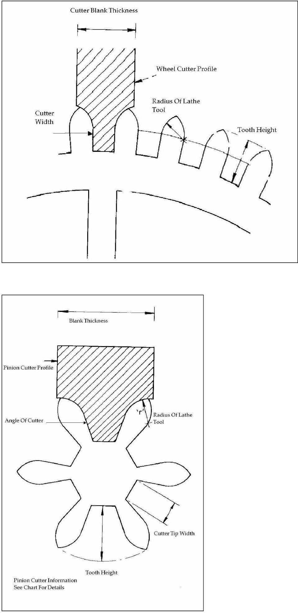
6 Wheel cutter making Data In Inches Module Lathe Tool Radius Cutter Tooth Width Tooth Height Cutter Blank Thickness

7 Pinion Cutter Making Data In Inches Module No of leaves Angle of cutter Radius of lathe tool Tooth height Cutter tip width Blank thickness deg deg deg deg deg deg As above As above As above As above As above As above

8 Module No of leaves Angle of cutter Radius of lathe tool Tooth height Cutter tip width deg deg deg deg deg deg As above As above As above As above As above Blank thickness

9 Figure 1 Base relieved to prevent rocking Figure 2 6mm Studding secured with Loctite and a 6mm nut

10 Figure 3 Drilling the 4 holes on the indexing disk. Figure 4 Boring the 7mm hole and using the 7mm collar as a gauge

11 Figure 5 The 6mm nut has been turned down to leave a 7mm sleeve and spotting through the index plate. Please note that the index plate has an extra set of holes, these were later filled with iron wire

12 Figure 6 The base, mounted in the lathe and showing the drill mark Figure 7 Turning the drill run out groove

13 Figure 8 Drilling the 4 holes 1/8 diameter on a cutter blank Figure 9 Tapping the main body of the tool 6mm, using a tapping aid and a finger plate on the drill press

14 Figure 10 Drilling the 1/8 hole 5/16 deep for the locating peg Figure 11 Drill right through with a 3/32 drill to aid peg removal, should it shear off in use

15 Figure 12 The tool screwed to the lathe Figure 13 A 1 inch square cutter blank set up in the tool and turning the surfaces true using the depth stop

16 Figure 14 Side view showing the ¼ offset of the cutter blank Figure 15 Setup for making pinion cutters. Slow speed with positive drive. Taper slide set to angle, depth stops in place, cross slide locked

17 Figure 16 Overhead view of 15 showing masking tape on the cross slide with reference marks Figure 17 Forming the radial faces of the cutter with a slitting saw

18 Figure 18 Removing waste Figure 19 Grinding the cutter faces

19 Figure 20 Cutter in use in my Chronos pinion mill

The Bonelle Tool and Cutter Grinder
 The Bonelle Tool and Cutter Grinder The grinder was constructed about 1987 and exhibited at the 89th Model Engineering exhibition where it was awarded a bronze medal (see ME Vol164 No 3868 page 273). Subsequently
Lathe Milling Attachment
 Lathe Milling Attachment By L C. MASON BY CLEVERLY stacking cold-rolled flat stock together, T-slots and slide for this lathe milling attachment are made without costly machinery. In fact, only two tools,
HONING LATHE DUPLICATOR CUTTERS
 Lay the flat face of the cutter or bit on the flat top surface of the hone with the rest of the cutter overhanging the edge. Rub the cutter or bit up and down the hone (Figure 24-44). Be sure to hold the
Twist Drill Grinding Attachment By Steven Skiprat Jackson June 2009
 Twist Drill Grinding Attachment By Steven Skiprat Jackson June 2009 Part 1. About the tool Part 2. Mounting the tool Part 3. Using the tool Part 1. About the tool This little gadget while not a precision
1.8 CRANKSHAFT OIL SEALS
 SERIES 60 SERVICE MANUAL 1.8 CRANKSHAFT OIL SEALS An oil seal is fitted between each end of the crankshaft and the bores of the flywheel housing and gear case cover to retain the lubricating oil in the
RETROFITTING THE X3 MILLING MACHINE (2)
") RETROFITTING THE X3 MILLING MACHINE (2) Dick Stephen continues with the mechanical modifications. Fitting the ball screws The 12mm 2mm pitch supplied by THK ball screws are delivered with the nut fitted
RETROFITTING THE X3 MILLING MACHINE (2) Dick Stephen continues with the mechanical modifications. Fitting the ball screws The 12mm 2mm pitch supplied by THK ball screws are delivered with the nut fitted
COLLEGE OF ENGINEERING AND APPLIED SCIENCE MACHINE SHOP TOOLS AND PRACTICES
 COLLEGE OF ENGINEERING AND APPLIED SCIENCE MACHINE SHOP TOOLS AND PRACTICES I. OBJECTIVE To provide an overview and basic knowledge of the University of Wyoming, College of Engineering, equipment, tools,
Resharpening Companion
 Resharpening Companion 10950 Correct Angles, Pictures, and Step-By-Step Instructions The Resharpening Companion is meant to be a guide and quick reference to help you resharpen. It is not meant to replace
Gate Leg Drop Leaf Table Plans
 Preparing the table top blanks: Cut and glue enough 3/4 stock to make three panels 40 long by 24 wide (they will be cut to final size at a later time). While the glue dries we will work on the legs. Preparing
MGB Chrome Bumper Conversion
 MGB Chrome Bumper Conversion Installation Instructions For 1974 1/2-1980 MGB This kit requires cutting, welding, and painting. Professional installation recommended. Note: Every MGB body is slightly different
Pole Lathe and Shave Horse Design
 Pole Lathe and Shave Horse Design These pictures and accompanying words are Copyright Michael Hughes February 2002. They are not to be re-produced, in part or whole, without permission from the author.
www.cornholesupplies.com
 www.cornholesupplies.com How To Build Regulation Cornhole Boards Home of the Original Cornhole Bags and Boards Supply List: 1-4' X 8' Piece of Plywood (pre sanded) 4-2" X 4" X 8' Studs (2 by 4s make sure
SHOP NOTES METAL SHAPER FOR YOUR SHOP
 SHOP NOTES METAL SHAPER FOR YOUR SHOP A METAL SHAPER is indispensable for certain machining operations where flat surfaces must be produced within very close limits, such as machining flats on castings,
UNITED STATES CUTTING TOOL INSTITUTE Product Groupings for Standards Activities CUTTING TOOL PRODUCTS
 CUTTING TOOL PRODUCTS 1. BORING ISO 5609 Boring bars for indexable inserts Dimensions ISO 6261 Boring bars (tool holders with cylindrical shank) for indexable inserts Designation JIS B 4128 Boring bars
The "DAVID" Steam Engine By Alan Marconett Hobbit Engineering HTTP://WWW.HobbitEngineering.com Alan@HobbitEngineering.
 The "DAVID" Steam Engine By Alan Marconett Hobbit Engineering HTTP://WWW.HobbitEngineering.com [email protected] (c) 2/20/03 The David steam engine is a simple oscillating steam engine, many plans
Permanent Magnetic Generator Construction Manual
 Permanent Magnetic Generator Construction Manual http://hojomotor.com Our Team Doing an On-site Assembly in Peru http://hojomotor.com Section 1) Introduction This manual describes how to build a 'permanent
It's large enough to handle most welding job shop projects, yet small enough to make it a worth while home-workshop tool
 It's large enough to handle most welding job shop projects, yet small enough to make it a worth while home-workshop tool H Craft Print Project No. 272 ERE'S a metal bender that will enable you to bend
ANSI APPROVED 04/11/2014 ANSI APPROVED 08/17/2011. 45 Reaffirmation ANSI APPROVED 02/28/2014. 45 Reaffirmation ANSI APPROVED 05/06/2013
 STANDARDS STATUS REPORT As of November 4, 2015 Note: Dates in RED indicate the last action taken; Highlighted Items Indicate New/Open Items; Grey items have been closed Document TC Status Comments ASME
DTU Animal Cart Programme
 DTU Animal Cart Programme TECHNICAL 21 RELEASE PIPE AND ROLLER DONKEY CART AXLES Development Technology Unit, Department of Engineering, University of Warwick, Coventry, CV4 7AL UK, tel: +44 (0)1203 523523
BUILDINGA 1/10 SCALE FLATBED TRAILER
 VOLUME 1, ISSUE 1 BUILDINGA 1/10 SCALE FLATBED TRAILER BUILT, DESIGNED & WRITTEN BY NATHAN MYERS MATERIALS: FEATURES: While the design was kept simple to allow anyone to be able to build their own trailer,
Hive Top Ventilation Shims
 Hive Top Ventilation Shims When preparing your bee hives for the winter, it is very important to provide for ventilation at the top of the hive. Through out the winter, the bees are expelling a lot of
How To Make A Spiral Fluted And Wire Wrapped Dagger Handle
 Making A Spiral Fluted and Wire Wrapped Dagger Handle By: Steve Culver, MS Part 1 Making A Spiral Fluted and Wire Wrapped Dagger Handle By: Steve Culver, MS After the rough handle material is drilled through
TOOLS FOR SELF RELIANCE REFURBISHING SHEET No 2. Registered Charity No 280437. Saws for Woodworking
 Registered Charity No 280437 Saws for Woodworking Issued December 2002 Registered Charity No 280437 page no 1 SAW TYPES Rip saw For cutting along the grain Crosscut saw [A smaller version is known as a
How to Build Your Own CornHole Game
 How to Build Your Own CornHole Game DIMENSIONS Here is a diagram with the basic measurements for the Cornhole board game. SUPPLIES 1/2 thick sheet of plywood one 4 x4 or two 2 x4 s 8 long 2 4 s (4) 4 1/2
Making Soft Jaws for a Bison 3 Jaw Lathe Chuck
 Making Soft Jaws for a Bison 3 Jaw Lathe Chuck By R. G. Sparber Copyleft protects this document. 1 My Bison lathe chuck has served me well for many years. One of its features is the ability to remove the
SPRITE and BIGFOOT DESKTOP CNC MACHINE KIT ASSEMBLY INSTRUCTIONS
 SPRITE and BIGFOOT DESKTOP CNC MACHINE KIT ASSEMBLY INSTRUCTIONS README FIRST: Thank you for purchasing your MyDIYCNC Desktop CNC Machine Kit. We hope this versatile and innovative machine brings you many
VCE VET ENGINEERING STUDIES
 Victorian Certificate of Education 2013 SUPERVISOR TO ATTACH PROCESSING LABEL HERE STUDENT NUMBER Letter Figures Words VCE VET ENGINEERING STUDIES Written examination Section Wednesday 20 November 2013
Making Wooden Hinges
 Making Wooden Hinges By Alex Reid - www.mokkou.jp Materials and tools used - 3.2mm straight router bit - 1/8 round-over router bit - Flush-cut straight bit (with bearing on bottom) - Finger-joint jig -
KNIFE GRINDER MATERIALS LIST & CONSTRUCTION TIPS by Michael Clerc [email protected]
 KNIFE GRINDER MATERIALS LIST & CONSTRUCTION TIPS by Michael Clerc [email protected] Materials List Minimum tools required: Drill press & Drill bits ("#7", "F", 5 / 16 ", ¼", 17/64", ½", "O", 1") Tap Handle
Slide the new steering column shaft through the steering column from the driver compartment.
 Slide the new steering column shaft through the steering column from the driver compartment. Push the column shaft through the steering column until the machined end is out past the column lower bushing.
Pepper Mill Instructions by Fred Kachelhofer
 by Fred Kachelhofer I have seen Nick Cook turn a pepper mill twice and read his article posted at http://www.nickcookwoodturner.com/articles.htm (follow link and then click on Pepper Mill ). I have had
Threaded-lid. Acorn. project that won t fall far from the lathe
 Threaded-lid Acorn A The fun Woodturner s project that won t fall far from the lathe By Nick Cook Above: Rich texturing to a 53 4" x 31 2" acorn box enhances the appeal of the Willard Baxter acorn shown
MODEL T10023 ACCESSORY KIT #1 FOR T10010/T10097 WET GRINDER
 MODEL T0023 ACCESSORY KIT # FOR T000/T0097 WET GRINDER INSTRUCTION SHEET Introduction The Model T0023 Accessory Kit # for the Model T000/T0097 Wet Grinder includes fixtures for sharpening small knives,
Turning Crow Calls -The Latta Method-
 Turning Crow Calls -The Latta Method- This tutorial will cover how to make a crow call using the molded reeds sets we sell and how to modify them to make a much better end product for you and your customers
Rebuild Instructions for 70001 and 70010 Transmission
 Rebuild Instructions for 70001 and 70010 Transmission Brinn, Incorporated 1615 Tech Drive Bay City, MI 48706 Telephone 989.686.8920 Fax 989.686.6520 www.brinninc.com Notice Read all instructions before
INSTRUCTIONS: LocknCharge Laptop Carts
 INSTRUCTIONS: LocknCharge Laptop Carts www.lockncharge.com Extra Tools required: Hammer, Philips head screwdriver, medium adjustable spanner. (Allen key supplied) (Panel colours for illustration purposes
4BT A/C Bracket Directions
 4BT A/C Bracket Directions This kit will be broken into smaller kits for ease of installation and recognition of hardware. Tools needed for install; 3/8 Ratchet 1/2 wrench 1/2 socket 9/16 wrench 9/16 socket
YUASA MILLING MACHINE ACCESSORIES & TOOLS
 97 HORIZONTAL / VERTICAL 5C COLLET INDEX 550 series 2 YEAR WARRANTY Spindle is manufactured with a taper seat in body frame. Rapid opening and closing is performed with a level collet closer with a leverage
Go-kart for little race-drivers
 Go-kart for little race-drivers Drill and drive. Go-kart What it lacks in speed, it more than makes up for in fun: the go-kart will excite little race-drivers. 1 Introduction It s only a go-kart, but it
Precision made in Europe. As per DIN 8606. The heart of a system, versatile and expandable.
 1 von 9 Precision made in Europe. As per DIN 8606. The heart of a system, versatile and expandable. Main switch with auto-start protection and emergency off. Precision lathe chuck as per DIN 6386 (Ø 100mm).
DIY CABINET REFACING INSTALLATION GUIDE
 DIY CABINET REFACING INSTALLATION GUIDE CABINET REFACING INSTALLATION Are you ready to reface your outdated cabinets? This guide will show you how to install your new Facelifters Cabinet Refacing Products
Cedar Cottage Doghouse Plans
 Overlapping cedar shingles add an element of charm to this medium size doghouse. The walls, floor, and trim are constructed of solid cedar, making it naturally weather resistant and provides excellent
Router Table Plans. www.bobsplans.com
 www.bobsplans.com Router Table Plans Increase the capabilities of your router with this weekend project. Features a sliding fence with EZ-Mount clamps. These clamps are simple to make and grip tightly
CNC Applications Speed and Feed Calculations
 CNC Applications Speed and Feed Calculations Photo courtesy ISCAR Metals. Turning Center Cutters What types of cutters are used on CNC turning Centers? Carbide (and other hard materials) insert turning
Home"" """"> ar.cn.de.en.es.fr.id.it.ph.po.ru.sw
 Home"" """"> ar.cn.de.en.es.fr.id.it.ph.po.ru.sw Milling of Grooves, Elongated Slots and Break-throughs - Course: Techniques for machining of material. Trainees' handbook of lessons (Institut fr Berufliche
How to Build a Poker Table
 How to Build a Poker Table www.pokertablematerials.com 10-Person Poker Table- 96 x 48 These are step by step instructions for building a poker table. The table will measure 48" x 96" and have a 4" wide
Modular Locomotive System Instruction Manual for HBK8 George Body Kit
 Modular Locomotive System Instruction Manual for HBK8 George Body Kit Roundhouse Engineering Co. Ltd. Units 6-10 Churchill Business Park. Churchill Road, Wheatley. Doncaster. DN1 2TF. England. Tel. 01302
Installation Instructions
 Installation Instructions 1. Position the unit onto bridging packers. These keep the unit away from any water sitting inside the frame. 2. Centralise the unit within the frame and pack the edges with appropriate
HOW TO MAKE A MOTOR BRACKET
 HOW TO MAKE A MOUNTING BRACKET FOR AN ELECTRIC MOTOR Often, brackets supplied with purchased items (e.g. electric motors or servos) are not ideally suited for fitting into our models or they are not supplied
Milling Milling milling cutter milling machines 1
 Milling Milling is a basic machining process by which a surface is generated progressively by the removal of chips from a workpiece as it is fed to a rotating cutter in a direction perpendicular to the
Introduction to JIGS AND FIXTURES
 Introduction to JIGS AND FIXTURES Introduction The successful running of any mass production depends upon the interchangeability to facilitate easy assembly and reduction of unit cost. Mass production
Gear PEPSI CAN STOVE INSTRUCTIONS
 Gear PEPSI CAN STOVE INSTRUCTIONS [NOTE: Updated Instructions are now available. The new stove is less likely to develop flame leaks and the fuel/air mixture is improved. Instructions for a simmer ring
SERVICE PARTS LIST PAGE 1 OF 6 BASE ASSEMBLY SPECIFY CATALOG NO. AND SERIAL NO. WHEN ORDERING PARTS 12" DUAL BEVEL COMPOUND MITER SAW B27A
 PAGE 1 OF 6 BASE ASSEMBLY 00 0 EXAMPLE: Component Parts (Small #) Are Included When Ordering The Assembly (Large #). SPECIFY CATALOG NO. AND NO. WHEN ORDERING PARTS 1 02-80-0050 Thrust Bearing (1) 2 05-80-0510
Children s Furniture Projects
 This is an excerpt from the book Children s Furniture Projects by Jeff Miller Copyright 2002 by The Taunton Press www.taunton.com CHILD S ROCKER KIDS ARE ALWAYS IN MOTION. It s not easy to get them even
Complete Dovetail Jig Instructions
 Complete Dovetail Jig Instructions 18 15 1 12 13 8 (22818) 19 17 16 4 3 6 14 5 9 9 11 10 2 PARTS LIST - COMPLETE DOVETAIL JIG Introduction Your new dovetail jig will cut Full Through Dovetails and three
Char-Lynn Spool Valve Hydraulic Motors. Repair Information. W Series Geroler Motors
 Char-Lynn Spool Valve Hydraulic Motors Repair Information W Series Geroler Motors with Parking Brake 004 Nut Key Ring, Retaining Bearing Ring, Retaining Ring, Retaining Washer (Thick), Pressure Washer,
DO NOT OPERATE LANCELOT OR SQUIRE WITHOUT FIRST ADJUSTING THE SAFETY GUARD. ( See Below)
") Assembly Instructions - Lancelot and Squire King Arthur s Tools (KAT) is pleased to present the first tandem mounted saw chain accessories whereby differing combinations of Lancelot and Squire may be paired
Assembly Instructions - Lancelot and Squire King Arthur s Tools (KAT) is pleased to present the first tandem mounted saw chain accessories whereby differing combinations of Lancelot and Squire may be paired
Woodturning Project Tutorials by Larry Hancock. 2004, 2005 Larry Hancock, turnedtreasures.com. Gavel Turning
 Woodturning Project Tutorials by Larry Hancock 2004, 2005 Larry Hancock, turnedtreasures.com Gavel Turning Before you can start to turn a gavel the design, size, and wood need selected. The design I used
METAL-TURNING LATHE Built from Stock Parts
 by Frank Beatty USING STANDARD PARTS and stock materials that are available almost anywhere, you can build this metalworking lathe with only a few tools. Because of simplification of the assembly in order
Char-Lynn Hydraulic Motor. Repair Information. 10 000 Series. October, 1997
 Char-Lynn Hydraulic Motor October, 1997 Repair Information Geroler Motor Two Speed 001 27 Retainer inside bore of valve plate bearingless motors only 4 15 16 3 6 35 Parts Drawing 25 2 2 1 19 17 36 40 47
Assembly Instructions Basic Folding-Leg Box Frame Style
 Assembly Instructions Basic Folding-Leg Box Frame Style Basic Folding Leg Cornhole Board Concept 1 2 12 3 1 2 3 15 16 4 1 4 52 9 R1 3 4 6 21 48 12 1 4 Bolt Washer 9 13 16 35 Washer Double Nut CornholePlayers.net
Building an Off-Center Fixture for Turning Pendants
 Building an Off-Center Fixture for Turning Pendants Turning a pendant off-center with most available metal pendant chucks means that you will have a significant amount of mass off center, which will limit
HALE PET DOOR INSTALLATION INSTRUCTIONS HALE STANDARD PANEL MODEL
 HALE PET DOOR INSTALLATION INSTRUCTIONS HALE STANDARD PANEL MODEL Please read these instructions carefully and completely before attempting to install Hale Pet Doors; they will guide you through the steps
MACHINING OPERATIONS AND MACHINE TOOLS
 MACHINING OPERATIONS AND MACHINE TOOLS 1. Turning and Related Operations 2. Drilling and Related Operations 3. Milling 4. Machining & Turning Centers 5. Other Machining Operations 6. Shape, Tolerance and
DUGARD. Machine Tools Since 1939. Dugard ECO Series Driven Tool, Slant Bed CNC Lathes. www.dugard.com
 DUGARD Machine Tools Since 1939 ECO Series Driven Tool, Slant Bed CNC Lathes www.dugard.com ECO Series - CNC Lathes Amazing speed, power, precision and durability all at an affordable price Rigid and Trustworthy
No. 57 Receiver Sight No. 57 SML Receiver Sight No. 66 Receiver Sight
 No. 57 Receiver Sight No. 57 SML Receiver Sight No. 66 Receiver Sight MOUNTING AND ADJUSTING MOUNTING LYMAN NO 57 RECEIVER SIGHT The No. 57 Sight is designed primarily for rifles with round receivers.
Chapter 6 Machining Center Carbide Insert Fundamentals
 This sample chapter is for review purposes only. Copyright The Goodheart-Willcox Co., Inc. All rights reserved. N10G20G99G40 N20G96S800M3 N30G50S4000 N40T0100M8 N50G00X3.35Z1.25T0101 N60G01X3.25F.002 N70G04X0.5
Sheet Metal Shearing & Bending
 Training Objective After watching the program and reviewing this printed material, the viewer will gain a knowledge and understanding of the principles and machine methods of shearing and bending sheetmetal
SHARPENING LATHE TOOLS
 SHARPENING LATHE TOOLS Version 1.4 By Jim Rodgers (925) 229-5773 www.jlrodgers.com Sharpening Lathe Tools 1. Purpose of sharpening a. Improve cut surface quality b. Speed project completion c. Ease amount
FREEBIRD THE ORIGINAL D.I.Y. ORNITHOPTER! Tools and Glue. Required Materials
 Do not try to make your ornithopter using "household materials". If you want it to fly, you have to build it right. FREEBIRD THE ORIGINAL D.I.Y. ORNITHOPTER! Wingspan: 16 inches Weight: 1/4 ounce The Ornithopter
Black Wolf POCKET BILLIARD TABLE INSTALLATION MANUAL. SERVICE DEPARTMENT P.O. BOX 68 BRISTOL, WI 53104
 Black Wolf TM POCKET BILLIARD TABLE INSTALLATION MANUAL www.brunswickbilliards.com SERVICE DEPARTMENT P.O. BOX 68 BRISTOL, WI 53104 51-905710-000 SEPTEMBER 2010 NOTE: Please use the instructions in this
These instructions will show you how to install an internal door into a non-loadbearing partition wall. The instructions are split into three parts.
 No 8 in the series of 'How to' brochures produced by PlaceMakers, New Zealand How to Frame and Hang a Door These instructions will show you how to install an internal door into a non-loadbearing partition
3000, 4000, 4100, 7500, 7700
 3000, 4000, 4100, 7500, 7700 Drum & Disc Brake Lathes s Identification READ these instructions before placing unit in service. KEEP these and other materials delivered with the unit in a binder near the
Screw Thread Design. Rev. 3-4-09
 Screw Thread Design Screw Thread Fundamentals A screw thread is defined as a ridge of uniform section in the form of a helix on either the external or internal surface of a cylinder. Internal threads refer
Dismantling and Reassembly Guide
 C3 Mini-Lathe Dismantling and Reassembly Guide A picture story book to help you dismantle and reassemble your Sieg C3 Mini-Lathe Arc Euro Trade Ltd. 10 Archdale Street, Syston, Leicester, LE7 1NA. Web:
LU6X-130 Instructions and Parts List (including LU6X Basic) Operating Instructions
 Operating Instructions") LORTONE LU6X-130 Item # 061-092 LU6X Basic Item # 061-090 LU6X-130 Instructions and Parts List (including LU6X Basic) Operating Instructions Introduction The LU6X is one the most versatile pieces of equipment
LORTONE LU6X-130 Item # 061-092 LU6X Basic Item # 061-090 LU6X-130 Instructions and Parts List (including LU6X Basic) Operating Instructions Introduction The LU6X is one the most versatile pieces of equipment
INSTALLATION INSTRUCTIONS for Bifold Doors (JII103)
") Thank you for selecting JELD-WEN products. Attached are JELD-WEN s recommended installation instructions for premium composite, hollow and solid core molded Bifold Doors. Bifolds are designed for fast
Thank you for selecting JELD-WEN products. Attached are JELD-WEN s recommended installation instructions for premium composite, hollow and solid core molded Bifold Doors. Bifolds are designed for fast
Dismantling and Reassembly Guide
 Super X3 Mill Dismantling and Reassembly Guide A picture story book to help you dismantle and reassemble your Sieg Super X3 Mill Arc Euro Trade Ltd. 10 Archdale Street, Syston, Leicester, LE7 1NA. Web:
Pump Skid Fabrication for Magnetic Coupling. Rick Soltis Chief Mechanic City of Bedford
 Pump Skid Fabrication for Magnetic Coupling Rick Soltis Chief Mechanic City of Bedford Contents Magnetic Couplings What They Are, How They Work, Where They re Used Fabrication and Manufacturing of Pump
Speed-Mat Rectangle Cutter
 Speed-Mat Rectangle Cutter 1 Honeycomb baseboard. 2 Left hold down. 14 3 Bottom hold down. 4 4 Left / right rule. 8 5 8 5 Left / right rule pointer. 1 6 Top / bottom rule. 7 Top / bottom rule pointer.
Model Marine Engine Requires No Castings
 Model Marine Engine Requires No Castings EXHAUST PORTS No. 29 No. 31 CROSSHEAD-GUIDE BRACKET No. 29 (STEAM PORT) CYLINDER BLOCK R CYLINDER COVERS No.31 CYLINDER SUPPORT No.29 (STEAM PORT) VALVE LINER VENT,
Product Guide SaraDrill
 Product Guide SaraDrill SARADRILL / A QUICK GUIDE Drilling from solid - a proven technology to drill large diameter holes on low horse power machines. Drilling from 49mm to 270mm diameter holes from solid
Machine devices, jig devices
 Machine devices, jig devices 853 K0697 Rolled thread studs DIN 6379 Material: Tempered steel. KIPP Rolled thread studs DIN 6379 Order No. D L B1 B2 Approx. weight g Surface finish: Thread rolled. Class
3. Loosen 3 x grub screws in the Dec end cap and unscrew the cap and counterweight shaft. NEQ6 Belt Modification Kit.
 NEQ6 Belt Modification Kit. Thank you for your purchase. Please read these instructions fully before fitting. Your package should contain 2 off 47 & 2 off 12 tooth aluminium pulleys 2 off belts 6mm wide
Building a Small Horizontal Steam Engine
 T Building a Small Horizontal Steam Engine HE small engine described in this article was built by the writer in his spare time about an hour a day for four months and drives the machinery in a small shop.
KITCHENS. Tip PAGE 1 FITTING YOUR KITCHEN GUIDE. How to mark out a kitchen. Tools required for installing a kitchen STEP ONE STEP TWO STEP THREE
 FITTING YOUR KITCHEN GUIDE How to mark out a kitchen PAGE 1 Before starting on the installation, measure 870mm from the lowest point of the floor and mark a datum line around the room to indicate where
CHARISMA SHOWER/TUB DOOR INSTALLATION INSTRUCTIONS
 CHARISMA SHOWER/TUB DOOR INSTALLATION INSTRUCTIONS IMPORTANT DreamLine reserves the right to alter, modify or redesign products at any time without prior notice. For the latest up-to-date technical drawings,
Panel/Hand Saw Kit Assembly Instructions
 Panel/Hand Saw Kit Assembly Instructions PLEASE READ THE FOLLOWING INSTRUCTIONS BEFORE BEGINNING Brief Summary You will be performing the following Tasks: 1. Determining the degree of shaping laying out
STEADYfast Stabilizer Installation Notes Fifth Wheel and Travel Trailers 11/23/13
 STEADYfast Stabilizer Installation Notes Fifth Wheel and Travel Trailers 11/23/13 (See Supplemental Instructions for trailers with heavy duty round footplates and/or Power Leveling Systems) PHONE SUPPORT
The tablesaw may be your shop s most valuable cutting. Crosscut Sleds. Foolproof. Innovative approach guarantees perfect results
 Foolproof Crosscut Sleds Innovative approach guarantees perfect results B Y A L A N T U R N E R The tablesaw may be your shop s most valuable cutting tool, but for precise, repeatable crosscuts it needs
10 deg 4 4.3 4.6 4.9 5.2 5.5 6 6.3 6.7 7.1 7.4 7.7 8 8.3 8.6. 12 deg 4.8 5.2 5.6 6 6.4 6.8 7.2 7.6 8 8.4 8.8 9.2 9.6 10 10.4
 max-prop utomatic Feathering Propeller Installation Instructions TR L LSSI 1) INTROUTION: Thank you for having chosen a Max-Prop automatic feathering propeller for your vessel. This instruction booklet
Fixturing systems Fixturing systems for measurement technology
 Fixturing systems Fixturing systems for measurement technology Innovations and new additions to range Sets Spannfix Eco complete set The set contains different supports, extension elements and stop units.
TRIMMING UNIT/DIAMOND MACHINE TST.13
 TRIMMING UNIT/DIAMOND MACHINE TST.13 REFERENCE BOOK rel. 02.15 TRIMMING UNIT/DIAMOND MACHINE TST.13 REL. 02.15 ENGLISH LANGUAGE 1 MACHINE DESCRIPTION TST.13 was designed and built for processing methacrylate.
Installation instruction CASAFLEX - Connecting piece DN 100
 1 CASAFLEX - 11 10 114,3 x 4,5 3 5 2 4 1 7 6 8 12 9 Do not begin work until you have read the installation instruction carefully. 1 internal backing sleeve 2 graphite packing 3 connecting piece 4 thrust
16 April 2012 1032011-F 1994-2002 Dodge Adjustable Track bar with Relocation Bracket 1
 16 April 2012 1032011-F 1994-2002 Dodge Adjustable Track bar with Relocation Bracket 1 BD Adjustable Track Bar w/bracket Dodge 2500-3500 4WD Models 1994-2002 Dodge 1500 4WD Model 1994-2001 P/N# 1032011-F
PRODUCT MANUAL - M090
 PRODUCT MANUAL - M090 MODEL 203/266 ELECTRIC CAN OPENER 1 SAFETY CAUTION: SEVERED CAN LIDS HAVE CUTTING EDGES. USE OF A PROTECTIVE GLOVE OR TONGS IS ADVISED WHEN HANDLING LIDS. WARNING To avoid risk of
OWNER S MANUAL Table Tennis Table Patent Pending
 OWNER S MANUAL Table Tennis Table Patent Pending Be sure to write your model number and serial number here for future reference. You can find these numbers printed on the bottom of the table. MODEL # T8179
SHELVES. www.tedswoodworking.com
 SHELVES It's rare that bookshelves look as interesting as the objects you display on them. After all, how much can you decorate the edges of your shelves and sides? This unit is unusual because the shelves
CAST IRON THE BASICS. Heatline - Cast Iron Radiators SMOOTH FLAT FILE TO REMOVE ANY SWARF. ONE TIME. ASSEMBLY. JOINTS SHOULD BE TIGHTENED.
 CAST IRON THE BASICS 1. DO NOT LIFT ON YOUR OWN. 2. ONLY LIFT THE RADIATOR VERTICALLY. 3. DO NOT LIFT MORE THAN 8/10 SECTIONS AT ANY ONE TIME. 4. POSITION THE RADIATOR BEFORE FINAL ASSEMBLY. 5. THIS PRODUCT