CONTAINER TERMINAL MANUAL
|
|
|
- Della Farmer
- 7 years ago
- Views:
Transcription
1 COTAIR TRIAL AUAL 89001

2 IPORTAT! Please read this manual carefully before unpacking the crane and using it for the first time. You will see the crane has many features, but there are a few things you should be aware of in order to obtain correct operation of the crane and to avoid damage. OLLOI TH ITRUCTIO ILL UR YOU T AXIU JOYT RO YOUR PURCHA! TH COTAIR TRIAL COTAI: 1 x antry with trolley and hoist 1 x Control unit 2 x Containers 1 x Base element (33 x 57 cm) with fitted crane rails 2 x OO scale tracks (22.6 cm) 8 x rail connectors, 16 screws for mounting the base element to a plate, 4 fittings 2
 with fitted crane rails 2")
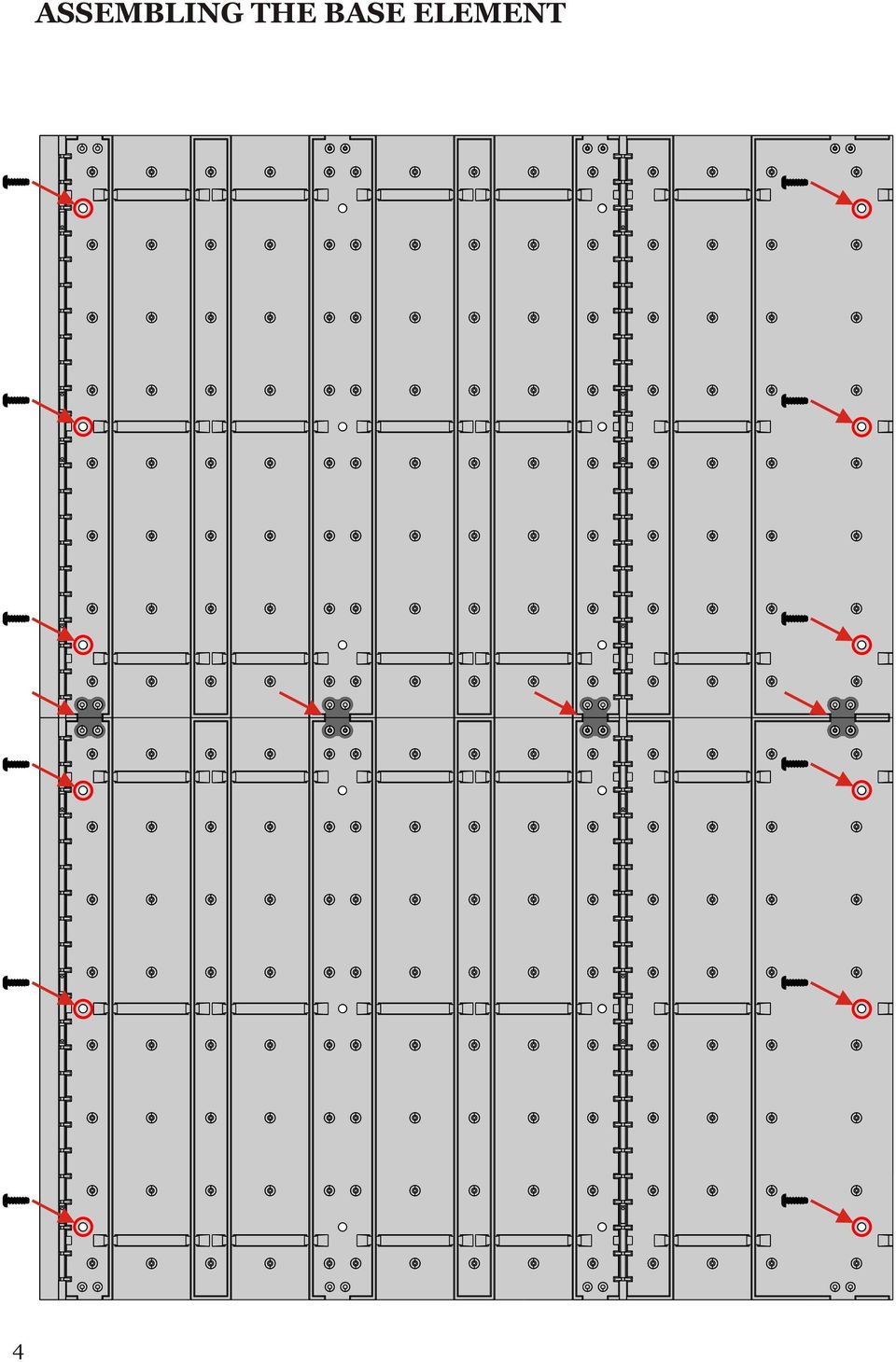
3 ITRODUCTIO Thank you for purchasing the HLJA Container Terminal. The crane is digitally controlled, but don t be frightened as the operation is simple and no specific experience with digital systems is needed to achieve full enjoyment of the crane. The basic model consists of the complete crane, control unit and two containers. One control unit can control up to three cranes. The basic model measures 33 x 57 cm, but it can be extended with further base elements limited only by power loss and your space! Additional containers can be purchased seperately. BOR YOU TART! Please be careful when unpacking. tart with the base elements that are placed in the special packaging at the bottom of the box. Do not unpack the crane until you have assembled the base element and installed the tracks where you want to place them. ABLI TH BA LT The base element consists of eight parts, 2 x 2 end sections and 2 x 2 central sections. The lower parts are assembled with the supplied fittings. ount the base element on to your baseboard. Use a 1.5 mm drill to make the holes in your baseboard, the holes have been drilled in the lower parts and screws are supplied. This is shown on photo 1 where you can also see how to connect the railway track to your layout. ITALLI TH TRACK Two OO scale tracks are included but you can install up to five tracks, four beneath the crane and one next to it (additional tracks can be purchased as accessories). hen you have decided where you wish to place the tracks offer them to the two central lower parts. Take the upper part to one of the lower parts where you want to install the track, and turn it over. On this side there are grooves that enable you to cut out the piece that fits the track (see Photo 2). Don t forget to connect the rails with the rail connectors as supplied, which can also be used to connect the tracks with lines to the power pack. Having done this the upper parts can be fitted to the lower parts of the base. You can also install wires for the ALLR Car-system, please refer to ALLR s instructions. ITTI TH ATRY AD TROLLY Carefully remove the trolley and the gantry from the packaging. Place the gantry on its base rails and the trolley on the gantry rails. All that remains prior to commencing container terminal operation is to connect it to the control unit and the power supply. Cut here Photo 1 Photo 2 3

4 4 ABLI TH BA LT
5 ITALLI TH TRACK 5

6 POR UPPLY You can use either AC or DC power packs. The voltage should be V, 2,5 A. Connect the control unit to your power pack and the crane tracks (see below). Do not turn on the power until you have read the next paragraph! TH COTROL UIT Power pack Crane PC Joystick The control unit is the core or the brain of the container terminal. Apart from controlling all functions of the crane, you can also adjust the speed with this unit. There are four connections: one for the power pack, one to the crane, one to a joystick and one for a PC. In the next section the use of the crane with the control unit will be explained. or use of Joystick and PC-connection please see our home page ( Prior to turning on the power please note these important points: All connections must be made before turning on the power. If operating with a joystick do not move the joystick during the start up phase, as this may cause a malfunction. If you unplug the joystick while still in use it will cause interruption to the signal. As soon as the power is turned on and the display shows HLJA the control unit is ready for use. If you connect a joystick it will be identified and calibrated during the start up phase.the joystick cannot be identified in the display during use. YOU AR O RADY OR OPRATIO! OPRATI TH ATRY Press button (ast) to drive right or (est) to drive left. 6

7 DRIVI TH TROLLY Press button (orth) to drive forwards or (outh) to drive backwards. DRIVI TH ATRY AD TH TROLLY AT TH A TI Press buttons and or and and or and. RAII OR LORI TH HOIT Hold button (unction) and then press button (to raise the trolley) or (to lower the trolley). IPORTAT! To prevent the strings that connect the hoist with the trolley from getting tangled avoid obstructions when you lower the hoist. If the hoist comes to rest at an angle raise it until it reaches the trolley and hold the buttons for a short while. hen you lower the hoist after having done so it will then be in a horizontal position. 7

8 TURI TH HOIT AROUD Hold button and then press button or. TURI O TH AT Press button (agnet). TURI O TH AT Press button. TURI TH POTLIHT O AD O Press the grey button (earchlight). 8

9 TURI TH ATRY LIHT O AD O Press button (antry Light). CHAI RO CRA 1 CRA 2 CRA 3 Hold button and then press button. This function is not possible when using a joystick or PC. CHAI DRIVI DIRCTIO Depending on how the control unit is placed in relation to the Container Terminal the driving direction of the gantry and the trolley can be changed by switching the switch. This influences both the control unit, the joystick and the PCsystem. HORT CIRCUIT In the case of a short circuit a flashing O appears in the display and the power supply to the crane will be turned off. hen the reason for the short circuit has been determined and cleared press button. 9

10 TTI TH PD Choose the address of the crane whose speed you want to change. Hold. Press or. P:t appears in the display. By pressing or you can choose the speed to be changed. These are the meanings of the specifications shown in the display: P:t = antry decoder P:to = Trolley decoder P:Hu = Hoist decoder Up P:Hd = Hoist decoder Down P:tr = Turn right P:tl = Turn left hen the desired speed has been reached press the button. P:4 appears in the display. 4 means the speed and may be varied after setting. ith the buttons and the speed can be increased or reduced. hen the button is released the new speed has been fixed. ith the exception of the antry and Trolley decoders Pro appears shortly in the display. RPRORAI TH CRA ADDR The antry and trolley decoders can be reprogrammed as follows: A) Choose a new crane address as described CHA RO CRA 1 CRA 2 CRA 3. Hold the buttons. B) Then press. C) Pro appears in the display. D) The Crane now reacts to its new address. ote: The Cv1 of the Crane decoder is programmed according to the Configuration Variables. 10

11 COIURATIO VARIABL: Trolley / Hoist Decoder Config. Variables unction Range Default etting Value CV1 Local address, Crane CV1 Local address, Crane CV1 Local address, Crane CV5 Trolley otor, maximum speed CV2 Trolley otor, start voltage CV3 Trolley otor, acceleration time CV4 Trolley otor, deceleration time CV55 Hoisting machine, Down peed V CV56 Hoisting machine, Up peed V CV57 Turn echanism, Turn right speed V CV58 Turn echanism, Turn left speed V CV61 agnet on V CV60 agnet function mapping CV59 earch Light function mapping CV120 Address Change CV (write only) antry Decoder Config. Values unction Range Defaut etting Value CV1 Local address, Crane CV1 Local address, Crane CV1 Local address, Crane CV5 antry otor, maximum speed CV2 antry otor, start voltage CV3 antry otor, acceleration time CV4 antry otor, deceleration time CV58 antry Light function mapping (2) CV60 lash Light config CV120 Address Change CV (write only)

12 ATUR ach movement can be adjusted by the user in 9 individual speedsteps. antry floodlight for the whole working area under the crane. Operator crane spotlights. 1 control unit can control up to 3 container cranes. 3 containers can be stacked. xtra add-on base elements for longer movements. (o practical track length limitation, except power loss) The crane base is extremely flexible to allow endless combinations of railway tracks, roadbeds and storage. Additional containers can be purchased. You can use all your favourite containers by adding a metal adapter (available as optional accessory) inside. The crane can be controlled by an existing DCC-system. Unique control system makes it possible to move the gantry and the trolley at the same time. Change of digital address: treat the crane as an ordinary locomotive. The crane is designed with asymmetrical gantry boom to allow harbour operation with container ships. The crane may be powered and controlled via the nearest available powered track (which means less wiring) if you operate via DCC. This system offers true turn key operation: no wiring between track and gantry as well as between gantry and trolley. User friendly operation also with several cranes on the layout: just twin-key toggle on the control unit. KP TRACK AD HL CLA! 12
 inside.")
13 ACCORI BA LT XTI O T # Base lement xtension et 2 central sections (33 x 22,6 cm) 4 rail connectors, 16 screws, 4 fittings This set will extend your basic Container Terminal et. # Track xtension et 2 OO cale tracks (each 22.6 cm long) 8 rail connectors or the installation of additional tracks in your Container Terminal. # HLJA Containers 4 Containers with metal adapter installed # etal adapters for containers 5 metal adapters After installing a metal adapter in an existing container, this can be used in the Container Terminal 13

14 14
15 LCTROIC TURTABL OO Detailed bridge with arch eathered one-piece pit otorized gear drive Holds engines up to 315 mm long Programmable indexing for 60 positions ACCORI #89011 (DC) #89012 (AC) # connecting tracks for ärklin C-tracks # connecting tracks for ärklin K-tracks 15

16 The container revolutionized global transportation. It is efficient and flexible: once the cargo is placed in the container it can be carried by train, by truck or on a ship. henever the container is to be moved from a train onto a truck or a ship this is done by the container crane which is the key to the whole operation. The HLJA digital Container Terminal opens up an exiting new world of entertainment and model reality. RBLARVJ 6 DK-5472 ØDRØ TL HLJA@HLJA.DK

GAUGEMASTER PRODIGY EXPRESS
 GAUGEMASTER PRODIGY EXPRESS DCC01 USER MANUAL Version 1.1 2011 T A B L E O F C O N T E N T S 1 Getting Started Introduction Specifications and Features Quick Start Connecting to Your Layout Running a Loco
Instruction Manual. This Manual covers the use of: SmartSwitch Servo Kit. DCC Stationary Decoder PLEASE READ THESE INSTRUCTIONS FULLY BEFORE USE
 built by Instruction Manual This Manual covers the use of: PLS-125 PLS-130 PLS-135 SmartSwitch Servo Kit SmartFrog DCC Stationary Decoder PLEASE READ THESE INSTRUCTIONS FULLY BEFORE USE Contents Introduction
INSTRUCTION MANUAL. FOR TECHNICAL ASSISTANCE: www.atlasrr.com dcc@atlasrr.com VERSION 3.2 ITEM #330
 LIMITED ONE-YEAR WARRANTY Atlas Model Railroad Company, Inc. warrants that this Commander will be free from defects in material and workmanship for a period of one year from the date of purchase. If this
Gantry Crane 1:87. Description. Packing contents. Unpacking. Roof assembly
 Gantry Crane 1:87 Description This gantry crane was built in large numbers and can still be found at many load tracks today. This finished model is constructed very finely in detailed plastic. Quiet miniature
Automated Container Handling in Port Terminals
 Automated Container Handling in Port Terminals Overview. Shipping containers revolutionized the movement of goods, driving change and efficiency throughout the global supply chain. The next revolution
Snap-It. This is an accessory (switch machine) decoder
 decoder") Snap-It $19.95 For use with most twin coil switch machines such as: Atlas, LifeLike, Peco, Bachmann, NJ, Rix, Kemtron and others Dimensions: 1.80" x 1.50" (46 x 38 mm) This is an accessory (switch machine)
Snap-It $19.95 For use with most twin coil switch machines such as: Atlas, LifeLike, Peco, Bachmann, NJ, Rix, Kemtron and others Dimensions: 1.80" x 1.50" (46 x 38 mm) This is an accessory (switch machine)
FG MOISTURE MONITOR Installation & Operation Manual
 FG MOISTURE MONITOR Installation & Operation Manual Issue 3.0 7/20/10 1 Contents SERVICE AND TECHNICAL SUPPORT... 2 INSTALLATION:... 3 MOISTURE SENSOR INSTALLATION:... 3 SENSOR CONNECTOR:... 5 MONITOR
COLOR TFT LCD MONITOR. User Manual
 COLOR TFT LCD MONITOR User Manual GENERAL INFORMATION Thank you for choosing our TFT LCD(liquid crystal display) monitor. This product employs integrate circuits, low power consumption, and no radiation
User manual DinaSys DTC/DTS and DTC/DTZ
 PiCommIT has developed the DinaSys DTC/DTS and DinaSys DTC/DTZ turntable controller for the Fleischmann / Marklin Turntables in scale H0, H0m, TT, N and Z. One of the most important starting point was
Hatton s MD4 Decoder. Thank you for purchasing Hatton s Decoders.
 Thank you for purchasing Hatton s Decoders. Hatton s MD4 Decoder Our decoder meets all NMRA DCC specifications and will give good performance out of the pack, however by using this manual, you can learn
Contractors Guide Central Inverter System Installation
 Contractors Guide Central Inverter System Installation Step By Step Procedures 2,200 Watt/VA 6 Step Installation 1. Mount Bottom Cabinet 2. Mount Top Cabinet 3. Install Batteries 4. Install Conduit 5.
ASSEMBLY MANUAL SE-4S35
 Automatic drive ASSEBLY ANUAL SE-4S35 AI-4S35 SG-4R35 Battery box otor unit Inter-4 hub CONTENTS WARNING 1 INSTALLATION CONITIONS Battery box Speed sensor Cable lengths and diameters otor unit Recommended
Circuit Breakers. NRC Series. NRC Series. 900 www.idec.com
 Switches & Pilot Lights Display Lights NRC series circuit breakers offer circuit protection which is far superior to using fuses in applications containing relay circuits, motor circuits, heater circuits,
*The above steps do not program an address into the decoder/loco, it allows you to acquire an already known address.
 PRODIGY ADVANCE, ADVANCE SQUARED, WIRELESS CONVERSION SET, AND EXPRESS TIPS AND TRICKS By Frank Verrico, M.R.C. Tech Support Copyright M.R.C. 2006/2007 When you get your new Prodigy Advance or Express
PRODUCTIVITY THROUGH INNOVATION 600 CONTROL DIRECT DRIVE TECHNICAL/OPERATION MANUAL
 Rev. D PRODUCTIVITY THROUGH INNOVATION 600 CONTROL DIRECT DRIVE TECHNICAL/OPERATION MANUAL 10 BORIGHT AVENUE, KENILWORTH NEW JERSEY 07033 TELEPHONE: 800-524-0273 FAX: 908-686-9317 TABLE OF CONTENTS Page
Dynamis User Guide. Contents
 Contents Introduction 3 Hardware overview Handset 4 Command station 5 Handset screen overview 6 Action key icons 7 Getting Started 8 How to use the joystick 9 How to configure the locomotive roster 9 How
8 Channel Status Input Panel model SIP-8
 Description The Sine Systems model SIP-8 Status Input Panel is to be used with the RFC-1/B Remote Facilities Controller. It consists of a long PC board mounted on a 1.75 inch (1U) rack panel. The SIP-8
2 Mega-Pixel PoE Plus Speed Dome Internet Camera ICA-HM620. Quick Installation Guide
 2 Mega-Pixel PoE Plus Speed Dome Internet Camera ICA-HM620 Quick Installation Guide Table of Contents Verify The Contents Inside Package Box... 3 Physical Installation... 4 Further Configuration...12 Verify
MTX-D, Oil Temperature/Pressure Gauge
 MTX-D, Oil Temperature/Pressure Gauge 1 Mounting and Sensor Installation... 3 1.1 Mounting the Gauge... 3 1.2 Oil Temp Sensor... 3 1.3 Oil Pressure Sensor... 3 2 Wiring... 3 2.1 Main Gauge Wiring... 4
Advantium 2 Plus Alarm
 ADI 9510-B Advantium 2 Plus Alarm INSTALLATION AND OPERATING INSTRUCTIONS Carefully Read These Instructions Before Operating Carefully Read These Controls Corporation of America 1501 Harpers Road Virginia
Digital I/O: OUTPUT: Basic, Count, Count+, Smart+
 Digital I/O: OUTPUT: Basic, Count, Count+, Smart+ The digital I/O option port in the 4-Series provides us with 4 optically isolated inputs and 4 optically isolated outputs. All power is supplied externally.
Manual of Toy Crane Machines
 Manual of Toy Crane Machines (TR1550, TR1850, TR1950, TR2050) Dated: 2010-4-13 Scheme-1 1 Scheme-2 WARNING Please Read This Manual Carefully Before You Turn On The Machine, And Beware Of Following Things:
5-port 10/100Base-TX Industrial Switch (314500) User s Guide
 User s Guide") 5-port 10/100Base-TX Industrial Switch (314500) User s Guide COPYRIGHT All rights reserved. No part of this publication may be reproduced, stored in a retrieval system, or transmitted in any form or by
5-port 10/100Base-TX Industrial Switch (314500) User s Guide COPYRIGHT All rights reserved. No part of this publication may be reproduced, stored in a retrieval system, or transmitted in any form or by
FPV MONITOR. User Manual
 FPV MONITOR User Manual Important Safety Instructions: Please read User Guide before using this product. Please keep User Guide for future reference. Please read the cautions to prevent possible danger
Technical Overview Add-on Sensors - Smoke Alarm. Get yours direct at: 01491 410913 www.theclimate.co.uk
 Technical Overview Add-on Sensors - Smoke Alarm Get yours direct at: 01491 410913 www.theclimate.co.uk OVERVIEW This kit contains a standard smoke alarm and relay pattress. The Kidde Smoke Alarm supplied
PRS X-axis E-chain installation: For tools with a 12 Z-Axis
 PRS X-axis Energy Chain (Echain) Installation Page -1- PRS X-axis E-chain installation: For tools with a 12 Z-Axis This kit is compatible with PRS Shopbots that have an X-axis cutting area of 96 to 144.
Multi-Protocol decoder 76 200 with Load regulation
 Multi-Protocol decoder 76 2 with Load regulation For locomotives with universal motors on digital layouts operating in the DCC and Motorola data format. Features 76 2 Load regulated multi-protocol decoder
MIC-WKT and MIC-WKT-IR
 MIC-WKT and MIC-WKT-IR Installation Manual Bosch Security Systems EN Installation and Operation Manual MIC-WKTI and MIC-WKT-IR Installation Manual EN 2 MIC-WKT and MIC-WKT-IR Washer Pump Drive Card Kits
TerraWave Solutions MIMO Site Survey Battery Pack (Part # TW-SSBP-007) Instructions For Use
 Instructions For Use") Standard Shipping Contents of the TW-SSBP-007: 1 qty Site Survey Battery Pack (Diagram 1) 1 qty Charger (Diagram 2) 1 qty RJ-45 Red (802.3af) POE Cable (Diagram 3) 1 qty 2 56 Volt Power Cord (Diagram 4)
Standard Shipping Contents of the TW-SSBP-007: 1 qty Site Survey Battery Pack (Diagram 1) 1 qty Charger (Diagram 2) 1 qty RJ-45 Red (802.3af) POE Cable (Diagram 3) 1 qty 2 56 Volt Power Cord (Diagram 4)
GSM Door Phone System
 GSM Door Phone System System Installation, Setting and Operation Manual User Manual (263-S V1) Please read this user manual completely before operating this system and keep it in a safe place for future
Procedure for testing the integrity of the Festo and Numatics valve stacks:
 Procedure for testing the integrity of the Festo and Numatics valve stacks: 1. Disconnect the Injection Cylinder Clevis from the Injection Lever; let the Injection Cylinder lean back clear of the Injection
POINTS POSITION INDICATOR PPI4
 POINTS POSITION INDICATOR PPI4 Advanced PPI with Adjustable Brightness & Simplified Wiring Monitors the brief positive operating voltage across points motors when they are switched Lights a corresponding
4.3-inch Back-Up Camera
 TM 4.-inch Back-Up Camera Model No.: PKC0BU4 Owner s Manual and Warranty Information Read these instructions completely before using this product. Retain this Owner s Manual for future reference. INTRODUCTION
Motorising the Peco Turntable - a different approach
 Motorising the Peco Turntable - a different approach Motorised model railway turntables seem to fall into two main groups: a) converted Peco turntables with motor attachments; b) expensive manufacturers'
NX-591NE-GSM NetworX GSM 3G HSPA+ Module Installation Sheet
 NX-591NE-GSM NetworX GSM 3G HSPA+ Module Installation Sheet The NX-591NE-GSM is a microprocessor-controlled GSM interface module used to connect the NetworX series of control panels to GSM cellular networks
www.sebury.com.cn Digital Keypad Use s Manual
 K3 K4 www.sebury.com.cn Digital Keypad Use s Manual Contents Introduction Introduction Specifications Intramural Interface Circuit 3 Mounting 3 Wiring 5 Power UP 7 Engineer Programming Mode 7 The K3/K4
INSTRUCTIONS AND PARTS LIST SINGLE GIRDER UNDERHUNG CRANE BRIDGE KITS 1/2 THRU 10 TON HAND GEARED AND MOTOR DRIVEN
 INSTRUCTIONS AND PARTS LIST SINGLE GIRDER UNDERHUNG CRANE BRIDGE KITS 1/2 THRU 10 TON HAND GEARED AND MOTOR DRIVEN JUNE, 1999 COPYRIGHT 1999, Columbus Mckinnon Corporation PART NO. 113533-71 Page 1 COLUMBUS
Complete Train Control. Run Your Trains, Not Your Track!
 Complete Train Control Run Your Trains, Not Your Track! DN163K0a Fits Kato N-P42 Genesis, PA-1, E8 and Other Locomotives N Scale Mobile Decoder DCC Plug N Play 1.5 Amp/2.0 Amp Peak 6 FX 3 Functions, 0.5
ABB i-bus EIB Shutter Actuators JA/S 2.230.1, JA/S 4.230.1, JA/S 8.230.1, JA/S 4.230.1M, JA/S 8.230.1M, JA/S 4.24.1
 Product Manual ABB i-bus EIB Shutter Actuators JA/S 2.230.1, JA/S 4.230.1, JA/S 8.230.1, JA/S 4.230.1M, JA/S 8.230.1M, JA/S 4.24.1 Intelligent Installation Systems Contents Page 1 Introduction.......................................
EXTERNAL DIMENSIONS AND PARTS
 FX2N-4DA SPECIAL FUNCTION BLOCK USER S GUIDE JY992D65901A This manual contains text, diagrams and explanations which will guide the reader in the correct installation and operation of the FX2N-4DA special
IPX AUTOMATIC IP NETWORK LOSS BACKUP A/B SWITCH INSTRUCTION BOOK IB6444-02
 IPX AUTOMATIC IP NETWORK LOSS BACKUP A/B SWITCH INSTRUCTION BOOK IB6444-02 TABLE OF CONTENTS DESCRIPTION 2 MOUNTING INSTRUCTIONS 2 HOW TO CABLE THE IPX 2/3 POWER SUPPLY INSTALLATION 3 OPERATION 3 CARE
2M IR Mini Dome Quick Installation Guide
 2M IR Mini Dome 2M IR Mini Dome Quick Installation Guide Please follow the installation steps below to set up 2M IR Mini Dome IP Camera. Check the package contents against the list below. See P.1 Physical
GSM Autodialer Professional GJD700 Speech & Text Autodialer
 Text Edit message GSM Autodialer Professional GJD700 Speech & Text Autodialer Introduction The GSM Autodialer Professional works in conjunction with standard alarm systems and makes use of your preferred
ENGLISH www.bandg.com www.simrad-yachting.com www.lowrance.com
 StructureScan HD Transom mount Installation Guide ENGLISH www.bandg.com www.simrad-yachting.com www.lowrance.com Warning: It is your sole responsibility to install and use the instrument and transducer(s)
Uninterruptible Power Supply. 500 kva - 750 kva
 9 315 Uninterruptible Power Supply 500 kva - 750 kva T1 and T3 Installation Addendum 164201244-001 Rev. A ------------------------------------------------------------------------ ------------------------------------------------------------------------
Econami Digital Sound Decoder Electric Quick Start Guide Software Release 1.3
 Econami Digital Sound Decoder Electric Quick Start Guide Software Release 1.3 Previous software versions included Notice The information in this document is subject to change without notice. SoundTraxx
Points Position Indicator (PPI1) for Points Motors with Common Ground
 for Points Motors with Common Ground") Points Position Indicator (PPI1) for Points Motors with Common Ground Monitors Points Action and Operates Leds on a Control Panel Monitors the brief positive operating voltage across points motors when
Points Position Indicator (PPI1) for Points Motors with Common Ground Monitors Points Action and Operates Leds on a Control Panel Monitors the brief positive operating voltage across points motors when
Secure Keypads for access control
 torm Secure Keypads for access control Strike Master Read this manual carefully before attempting to install, program or operate the STORM AXS Strike Master Keypad. After installation the Command Summary
Installation, Operation & Service Manual
 Installation, Operation & Service Manual 0RQLWRU Pulse Monitor Software Version 1 0 1 Pulse Monitor Card Software Revision 1 4 0 Pulse Monitor Card Product Revision 0 1 0 0 February, 2007 Copyright 2007,
UM-X Field display for continous level sensors
 Technical Documentation Field display for continous level sensors 10/2007 Edition: 1 Item No.: 207120 FAFNIR GmbH Bahrenfelder Str. 19 D-22765 Hamburg Telephone: +49 (0)40-39 82 07-0 Fax: +49 (0)40-3 90
Model SETR-50 and SETR-51 Trim Tab Control
 Model SETR-50 and SETR-51 Trim Tab Control Pictured above is the SETR-50 with black switches on a gray background. The SETR-51 is identical except for the color, wherein it has black switches on a black
Installation and User s Manual Global Tracking and Tracing System. GTTS-2000Bi
 Installation and User s Manual Global Tracking and Tracing System GTTS-2000Bi Version 1.4 - January 2016 T +31570 606088 E info@gtts.eu W www.gtts.eu Page 1 of 11 1. Preface The information in this Installation
Multi-Protocol decoder 76 400
 Multi-Protocol decoder 76 For locomotives with DC motors on digital layouts operating in the DCC- and Motorola data format. Features Regulated multi-protocol decoder for DCC and Motorola Suitable for DC
BLOCK OCCUPANCY DETECTOR WITH SEMAPHORE OPERATION BOD1/DAP4-BR
 BLOCK OCCUPANCY DETECTOR WITH SEMAPHORE OPERATION BOD1/DAP4-BR This Block Occupancy Detector recognises the current drawn by moving trains within a block, and can operate a number of built-in programs
LINE POWERED ADA TELEPHONE USER S MANUAL Use With Part Numbers 11-580, 11-581, 11-582, 11-583, 11-585,11-586 and 11-589
 LINE POWERED ADA TELEPHONE USER S MANUAL Use With Part Numbers 11-580, 11-581, 11-582, 11-583, 11-585,11-586 and 11-589 6200 Brent Drive, Toledo, Ohio 43611 Phone: 800-837-1066 Fax: 419-729-5764 Email:
Application/Connection Examples
 This Quick Start Guide is designed to familiarize the user with the connection and configuration of the DTS-305 DIN rail mounted single / 3 phase power & energy meter with RS-485 or TCP communications.
SECTION G2: CABLE PROCESSOR MODULE MAINTENANCE
 SECTION G2: CABLE PROCESSOR MODULE MAINTENANCE Cable Processor Module overview WARNING! When tipping the Cable Processor Module back, (after removing the toggle arm pin), use extreme caution not to drop
Rules for Construction of Overhead and Gantry Cranes (Top Running Bridge, Multiple Girder)
") ASME NOG-1 2015 (Revision of ASME NOG-1 2010) Rules for Construction of Overhead and Gantry Cranes (Top Running Bridge, Multiple Girder) AN AMERICAN NATIONAL STANDARD ASME NOG-1 2015 (Revision of ASME
ASME NOG-1 2015 (Revision of ASME NOG-1 2010) Rules for Construction of Overhead and Gantry Cranes (Top Running Bridge, Multiple Girder) AN AMERICAN NATIONAL STANDARD ASME NOG-1 2015 (Revision of ASME
Drayton Digistat +2RF/+3RF
 /+3RF Programmable Room Thermostat Wireless Model: RF700/22090 Model: RF701/22092 Power Supply: Battery - Thermostat Mains - Digistat SCR Invensys Controls Europe Customer Service Tel: 0845 130 5522 Customer
KNX R. Rain Sensor. Installation and Adjustment
 EN KNX R Rain Sensor Installation and Adjustment 1 Content 1. Description... 3 1.1. Technical specifications... 3 2. Installation and commissioning... 4 2.1. Installation notes... 4 2.2. Location... 4
Laboratory Construction Guidelines Vicon MX Systems
 Laboratory Construction Guidelines Vicon MX Systems These Vicon MX Laboratory Construction Guidelines illustrate how to prepare a life sciences laboratory for installation of your new Vicon MX motion measurement
TS510 & TS500. Installation & User Guide. Compatible Equipment
 Installation & User Guide Compatible Equipment TS510 REM - Remote Keypad 9040 - Loudspeaker DC54/58 - Digital Communicator SD1+ - Speech Dialler 496525 Issue A 1 of 10 TS510 and TS500 Overview Introduction
mecotron Safety relay ESTOP-2 For emergency stop monitoring
 E0006 000824 Safety relay E-2 For emergency stop monitoring Description The safety module E-2 for emergency stop monitoring is used for safety breaking one or more circuits and is designed to be incorporated
How To Program An Autodialer
 GJD HYL005 GSM Autodialer Instruction Manual Please read these instructions before you start the installation Features: LCD display. Programmable 9 x 32 digit phone numbers for each trigger. 10 second
omega.com ΩOMEGA RS232 Multi-Drop www.omega.com FMA1600-MDB Multi-Drop Box
 omega.com ΩOMEGA RS232 Multi-Drop www.omega.com FMA1600-MDB Multi-Drop Box 1 3/29/2010 Rev.0 DOC-OMEGABB9MAN 2 Introduction FMA1600-MDB Multi-Drop Box Operating Bulletin The FMA1600-MDB Multi-Drop Box
CYMAQ Marking System AS200 + DS7050 N-14
 CYMAQ Marking System AS200 + DS7050 N-14 Serial Number: 13716 CYMAQ www.cymaq.com INDEX 1. PRESENTATION AND GENERAL POINTS 1.1. General Points 1.2. Identification plate 2. MACHINE CHARACTERISTICS 2.1.
MAKING MODERN LIVING POSSIBLE. AK-SC255 On-Site Installation Guide DANFOSS ELECTRONIC CONTROLS & SENSORS
 MAKING MODERN LIVING POSSIBLE AK-SC255 On-Site Installation Guide DANFOSS ELECTRONIC CONTROLS & SENSORS How to Use This Guide Read this Guide completely as you install and start up your new AK-SC 255 controller.
HP 2530 8-Port Switches Quick Setup Guide
 HP 2530 8-Port Switches Quick Setup Guide The switch drawings in this document are for illustration only and may not match your particular switch model. For more detailed instructions and information to
Lighting Controls ! WARNING RISK OF ELECTRIC SHOCK. Installation Instructions DESCRIPTION
 GE Lighting Installation Instructions Lighting Controls Centralized Lighting Control Panel Interior Catalog Number CLCINTxx DESCRIPTION The Centralized Lighting Control System is a small network of relay
 ABLOY DA60 SWING DOOR OPERATOR Installation and commissioning manual Abloy Oy An ASSA ABLOY Group company APPROVALS / STANDARDS Low Voltage directive 7//EEC as amended by the directive 9/68/EEC EMC directive
(I) s(t) = s 0 v 0 (t t 0 ) + 1 2 a (t t 0) 2 (II). t 2 = t 0 + 2 v 0. At the time. E kin = 1 2 m v2 = 1 2 m (a (t t 0) v 0 ) 2
 s(t) = s 0 v 0 (t t 0 ) + 1 2 a (t t 0) 2 (II). t 2 = t 0 + 2 v 0. At the time. E kin = 1 2 m v2 = 1 2 m (a (t t 0) v 0 ) 2") Mechanics Translational motions of a mass point One-dimensional motions on the linear air track LD Physics Leaflets P1.3.3.8 Uniformly accelerated motion with reversal of direction Recording and evaluating
Mechanics Translational motions of a mass point One-dimensional motions on the linear air track LD Physics Leaflets P1.3.3.8 Uniformly accelerated motion with reversal of direction Recording and evaluating
FTDI VCP DRIVER (free) (WIN/MAC/LINUX) http://www.ftdichip.com/drivers/vcp.htm
 (WIN/MAC/LINUX) http://www.ftdichip.com/drivers/vcp.htm") 002 - CONNECTING THE PRINTER Now that you have an idea what 3D printing entails, we can continue and connect the printer to your computer. First make sure you have a computer with a decent amount of RAM
002 - CONNECTING THE PRINTER Now that you have an idea what 3D printing entails, we can continue and connect the printer to your computer. First make sure you have a computer with a decent amount of RAM
VOYAGER 570G. 744A Sprayer Control
 VOYAGER 570G 744A Sprayer Control U S E R M A N U A L U S E R M A N U A L Table of Contents CHAPTER 1 - INTRODUCTION...1 SYSTEM CONFIGURATIONS...1 KIT CONTENTS...3 CONTROL HOUSING ASSEMBLY...5 CHAPTER
RAEGuard EC FGM-13XX
 RAEGuard EC FGM-13XX User s Guide P/N 033-4102-000 Rev B May 2007 - READ BEFORE OPERATING - This manual must be carefully read by all individuals who have or will have the responsibility of using, maintaining,
MODEL T10023 ACCESSORY KIT #1 FOR T10010/T10097 WET GRINDER
 MODEL T0023 ACCESSORY KIT # FOR T000/T0097 WET GRINDER INSTRUCTION SHEET Introduction The Model T0023 Accessory Kit # for the Model T000/T0097 Wet Grinder includes fixtures for sharpening small knives,
Setting Up the Cisco Unified IP Phones
 CHAPTER 3 This chapter includes the following topics, which help you install the Cisco Unified IP Phones on an IP telephony network: Before You Begin, page 3-1 Understanding the Cisco Unified IP Phone
Complete Train Control. Run Your Trains, Not Your Track! 1 PR3 Programmer 1 USB Cable 1 This Instruction sheet
 PR3 Complete Train Control Run Your Trains, Not Your Track! PR3 Decoder Programmer USB Programmer/Interface PR3 Features n Multifunction USB 2.0 PC connectivity for your railroad n Digitrax SoundLoader
MAKING MODERN LIVING POSSIBLE. living connect. Installation and User Guide. Danfoss heating
 MAKING MORN LIVING POSSIBLE Danfoss heating living connect Installation and User Guide Contents 1.0 System overview... 3 2.0 Overview of display and control buttons... 3 3.0 Installation - step by step...
Setting Up the Cisco IP Phone
 CHAPTER 3 This chapter includes this following topics, which help you install the Cisco IP Phone on an IP telephony network: Before You Begin, page 3-1 Installing the Cisco IP Phone, page 3-6 Adjusting
Glossary of Common Crane Ter ms:
 Glossary of Common Crane Ter ms: 26 Adjustable brakes: Electro-mechanical device to control crane deceleration. Bridge beam: Traveling beam connected to end trucks - supports trolley hoist and load. Bumpers:
Technocrane s. r. o. Podnikatelská 19 CZ - 301 00 Plzeň Czech Republic
 Technocrane s. r. o. Podnikatelská 19 CZ - 301 00 Plzeň Czech Republic Tel: +420-377889111 Fax: +420-377889100 info@supertechno.com www.supertechno.com IČO: 26353458 DIČ: CZ26353458 P r i c e l i s t Telescopic
BLOOD COLLECTION MIXER
 USER S MANUAL BLOOD COLLECTION MIXER Model CM735 No. CAT.CM73522Ce Centron Technologies Corporation 319-25 Sadang-4-dong, Dongjak-ku Seoul, Korea 156-823 Tel. +82-2.522.7807 Fax +82-2.522.7806 Table of
GLOLAB Universal Telephone Hold
 GLOLAB Universal Telephone Hold 1 UNIVERSAL HOLD CIRCUIT If you have touch tone telephone service, you can now put a call on hold from any phone in the house, even from cordless phones and phones without
Installation and Operation Guide PD4600 Series Converter Replacement
 Installation and Operation Guide PD4600 Series Converter Replacement Extended warranties are available for purchase at www.progressivedyn.com Member Thank you for selecting Progressive Dynamics as your
Operation Manual. Plasma torch height controller. Model: Compact THC Controller 150
 Operation Manual Plasma torch height controller. Model: Compact THC Controller 150 Notes on safety WHEN THE DEVICE IS IN OPERATION, VOLTAGE HAZARDOUS TO HEALTH AND HUMAN LIFE IS PRESENT INSIDE THE HOUSING
AC SERIES-C TYPE DUAL CONNECTORS JACK/XLR
 AC SERIES-C TYPE DUAL CONNECTORS JACK/XLR The AC Series C type chassis receptacles feature two connectors in the one space saving housing. A combined XLR female receptacle together with a 6.35mm (1/4 )
How To Make A Feedback Decoder For A Model Railroad
 BMD16N version 1.2 Feedback decoder with 16 contacts for the S88-bus Compatible with a.o. Märklin Digital, Uhlenbrock Intellibox, Fleischmann Twin-Center and LDT HSI-88 Compatible with the s88-n standard
WIRELESS STATUS MONITOR
 INSTALLATION INSTRUCTIONS WIRELESS STATUS MONITOR (WSM or AUWSM) The most current version of this document is available for download at: http://www.ir-swa.com P/N: M053-032-D Schlage 245 W. Roosevelt Road,
Installation GUIDE IMPORTANT: KEEP THIS MANUAL AND THE PRODUCT ID LABEL IN A SAFE PLACE
 Installation GUIDE IMPORTANT: KEEP THIS MANUAL AND THE PRODUCT ID LABEL IN A SAFE PLACE 1. Product description The device is an external module capable of connecting Panasonic air-conditioning units into
SEQUEL ASSEMBLY INSTRUCTIONS. 6003 Compact Desk CUSTOMERSERVICE@BDIUSA.COM
 BIUSA.COM CUSTOMERSERVICE@BIUSA.COM Component List Sequel is engineered for easy assembly. Carefully follow this procedure to prevent any damage. A - 4mm Hex Wrench B - 1/4-20 x 12 mm Flat Head Machine
ECEN 1400, Introduction to Analog and Digital Electronics
 ECEN 1400, Introduction to Analog and Digital Electronics Lab 4: Power supply 1 INTRODUCTION This lab will span two lab periods. In this lab, you will create the power supply that transforms the AC wall
AR-721U/721K/661U User s Guide
 AR-72U/72K/66U User s Guide Feb. 6, 2004 Table of Contents Page. Main Feature --------------------------------- 3 2. AR-72U Installation --------------------------------- 4 2. Steps ---------------------------------
MasterControl. Central unit for digital control EasyControl. Manual. Art.-Nr. 40-01007
 Central unit for digital control EasyControl Art.-Nr. 40-01007 Manual !! Information and tips: www. tams-online.de!!! Warranty and service: Tams Elektronik GmbH Rupsteinstraße 10 D-30625 Hannover fon:
HP UPS R1500 Generation 3
 HP UPS R1500 Generation 3 Installation Instructions Part Number 650952-001 NOTE: The rating label on the device provides the class (A or B) of the equipment. Class B devices have a Federal Communications
E E V R E - R S - O S L O A L R
 Solar Eye User Manual Edition JIANGSU EVER-SOLAR NEW ENERGY CO., LTD. Revision History Date Edition Specification 17/08/2011 1.0 Create File 02/09/2011 1.1 Add Micro SD function description www.ever-solar.com
Directory chapter 02 - DIN Power (to 6 A) Types D, E, F, FM, 2F, F9, interface connectors I/U 02. 01. Technical characteristics types D and E... 02.
 Types D, E, F, FM, 2F, F9, interface connectors I/U 02. 01. Technical characteristics types D and E... 02.") Directory chapter 02 - () Types D, E, F, FM, 2F, F9, interface connectors I/U Page Technical characteristics types D and E.............................. 02.10 Type D connectors.................... 02.11
Directory chapter 02 - () Types D, E, F, FM, 2F, F9, interface connectors I/U Page Technical characteristics types D and E.............................. 02.10 Type D connectors.................... 02.11
40.3. Control Relays and Timers
 .3 Contents EASY500/700/800 Intelligent Relays........ EASY/MFD Expansion Modules............ MFD Intelligent Relays................... EASY/MFD Communication Modules....... EASY/MFD Power Supplies, Accessories
71-4198-251 2/03. Lionel CW-80 Transformer Owner s Manual
 71-4198-251 2/03 Lionel CW-80 Transformer Owner s Manual Congratulations! Congratulations on your purchase of the Lionel CW-80 Transformer! This device combines a high output control unit and an internal
MTX-D, Boost/Shift Gauge
 MTX-D, Boost/Shift Gauge 1 Mounting and Sensor Installation... 3 1.1 Mounting the Gauge... 3 1.2 MAP sensor... 3 2 Wiring... 3 2.1 Main Gauge Wiring... 3 2.2 MAP sensor wiring... 4 2.3 Tach signal wiring...
Tilt switches N3 / N4... MEMS technology, one or two axis. Use. Options. + long lifetime and highly reliability due to mechanism-free MEMS technology
 Tilt switches MEMS technology, one or two axis N3 / N4... + long lifetime and highly reliability due to mechanism-free MEMS technology + combinable output signals + one or two axis measurement + tilt range