PIPING DRAWINGS BASICS N.P.TODKAR
|
|
|
- Phebe Baldwin
- 9 years ago
- Views:
Transcription
1 PIPING DRAWINGS BASICS N.P.TODKAR

2 There are two types of views used in the piping drawings: a) Orthographic- Plans and Elevations b) Pictorial - Isometric Views Piping layout is developed in both plan view and elevation view and section details are added for clarity wherever necessary. These drawings are called the General Arrangement of Piping. In complex piping system, especially within the unit/plant building where orthographic views do not illustrate the details of design, pictorial view in isometric presentation is drawn for clarity.

3

4

5

6

7

8 The Indian Standard IS10711 standardises the drawing sheets as below: SIZE OVERALL DIMENSIONS in mm A0-841 x 1189 A1-594 x 841 A2-420 x 594 A3-297 x 420 A4-210 x 297

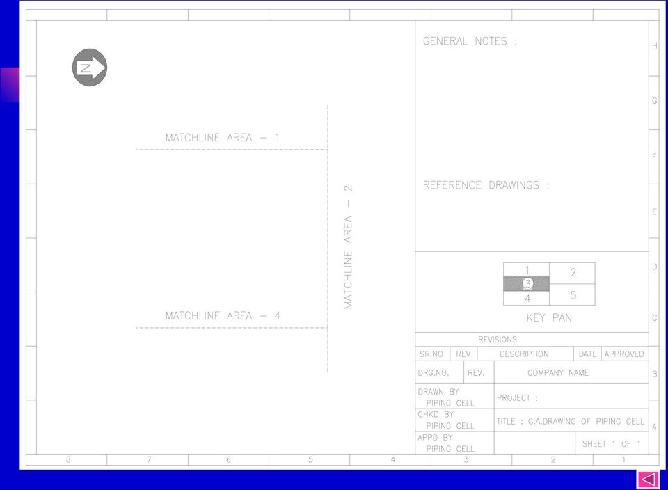
9 HOW TO START THE PIPING GA? Obtain the drawings numbers and fill in the title block, with the drawing number and title at the bottom right hand corner of the sheet. Place the north arrow at the top left/right hand corner of the sheet to indicate plant north. Do not plan drawing in the area above the title block of drawing, as this is allotted for general notes, number and title of reference drawings, brief description of changes during revision and the bill of materials wherever applicable. Process equipment and piping have priority on the Piping GA. The piping drawings are started after fixing positions of the equipments. Equipment layout is reproduced on the Piping GA to its scale and drawn on the reverse side in case of manual drafting.

10 In case of CAD separate layer is used. The major primary beams and secondary beams are also shown if area covered is indoor. Pertinent background details which govern piping routing, such as floor drains, HVAC ducting, electrical and instrument cable trays, etc. are also drawn in faint on the reverse. Utility stations are also established so that most convenient utility header routing can be carried out.

11
12 Order of importance/preference of pipe lines in a piping GA 1. Alloy steel/special material of construction. 2. Large bore piping 3. High temp/high pr. Piping 4. Lined piping 5. C. S. Process Piping 6. Utility piping

13 DEVELOPMENT OF PIPING GENERAL ARRANGEMENT DRAWING The piping drawings should be developed in such a way that all the process requirements are met with. It is not always possible for the piping drawing to follow exactly the logical arrangement of the P & IDs. Sometimes lines must be routed with different junction sequence and line numbers and subsequently the list may be changed. Performance and economics have to be considered in parallel while deciding the routing. Piping is represented by single lines up to a size of 150NB and double lines for sizes 200NB and above. This is to save the time of drafting and to avoid confusion. In single line representation only the center line of the pipeline is drawn using solid line and in double line representation the actual size to scale is drawn with center

14 Line numbers are shown against each line exactly in the same way as represented in the P&I diagrams. The change in specification should be shown in line with P&I diagram. This change is usually indicated immediately to the downstream of the valve, flange or equipment. Valves should be drawn to scale with identification number from the P&ID marked thereon. Draw valve hand wheels to scale with stem fully extended. If it is lever operated, then the movement of handle position should be marked. If a valve is chain operated, note the distance of the chain from the operating floor. Show location of each instrument connection with encircled instrument number taken from P&ID. Similar arrangement shall be shown as typical detail or covered in a separate company standard as Instrument Hook-up drawings.

15 Draw plan view of each floor of the plant and these views should indicate how the layout will look like between floors as seen from top. Each line should be identified by line number and should also show the insulation, tracing requirements, etc. Lines, if required, shall be broken to show the required details of hidden lines without drawing other views. Do not draw details that can be covered by a note. Draw plan to a larger scale for any part needing more details and identify it as Detail A, etc. Draw part isometrics sketches or part elevations to clarify complex piping or piping hidden in the plan view. Full sections through the plant may be avoided if isometric drawings are drawn for the lines. Part sections where required shall be shown to clear the hidden details in plan. Sections in the plan views are identified by numbers say 1-1, 2-2, etc. and details by alphabets, e.g. Detail A.

16 FIG.2: TYPICAL GENERAL ARRANGEMENT OF PIPING

17 FIG.3: TYPICAL PIPING ISOMETRIC DRAWING

18 Plant North - The direction should be so selected as to facilitate easy checking of GA with Iso Isometric drawing should also include the following information: Dimensions and angles. Reference number of P & IDs, GA Drawings, line numbers, direction of flow, insulation and tracing. Equipment location and equipment identification. Give nozzle identification on the connected equipment. Give the details of flange on the equipment if the specification is different from the connecting piping. Size and type of every valve/ Direction of operation. Size and number of control valve. Location, orientation and number of each equipment.

19 Field weld - preferred in all directions to take care of site variations. Can also be covered with a general note. Location of high point vents and low point drains. Covered with a standard arrangement note. Bill of Material. Requirements of stress relieving, seal welding, pickling, coating, etc.

20

21
22
23
24 SPOOLS A spool is an assembly of fittings, flanges and pipes that may be prefabricated. It does not include bolts, gaskets, valves or instruments. A spool sheet is an orthographic drawing of a spool drawn either from piping GA or from an iso sheet. Each spool sheet shows only one type of spool and, Instructs welder to fabricate the spool Lists the cut lengths of pipe, fittings and flanges etc. needed to make the spool Gives material of construction and any special treatment of finished piping Indicates how many spools of the same type are required
25 DIMENSIONING OF DRAWINGS Sufficient dimensions to be given for positioning equipment and for erecting piping. Duplicating dimensions in different views should be avoided, as this may lead to errors if changes are made. Reserve horizontal dimensions for the plan view. If single pipe is to be positioned or a pipe connected to nozzle is to be indicated, then show the centre line elevation and mark as C. If several pipes are sharing a common support, show elevation of Bottom of Pipes and mark as BOP EL. This is more applicable to non-insulated lines.
26 In case of several pipes on a pipe rack, show the Top of Support elevation and mark as TOS EL. In case of buried pipelines in trench, show elevation of bottom of pipes. In case of drains and sewers, the Invert Elevation of the inside of the pipe is marked as IE.
27
28
29 Centre lines of the equipment and pipelines shall be located with reference to the building column centre lines or the co-ordinates which can be considered as a reference base. The distance between the lines shall be dimensioned centre line to centre line. The horizontal nozzles on the equipment shall be located from centre to flange face in plan. For vertical nozzles show Face of Flange elevation (FOF). For valves, instruments and non-standard equipments, show the dimensions from flange face to flange face.
30 Flanged valves are located with dimension to flange faces. Nonflanged valves are dimensioned to their centres or stems. For flanged joints show a small gap between dimension lines to indicate gasket. Flanged joints can also be shown without gasket but cover the same with a general note and include gasket thickness in the valve or equipment dimensions. For Finished Floor (FF) the elevation shall be the high point of the floor.
31
32 For foundation the Top of Grout (TOG) elevation is shown. Show dimensions outside the drawn view - do not cut pictures. Draw dimension line unbroken with fine line. Write dimension just above the horizontal line. For vertical lines write sideways. The dimension lines can be terminated with arrow heads or oblique dashes. If series of dimension is to be shown, string them together. Show overall dimension of the string of dimensions. Avoid one of the break-up dimensions to omit repetition and error during changes. Do not omit significant dimension other than fitting make up.
33 For field run piping, give only those dimensions which are necessary to route piping clear of equipments and other obstructions. Locate only those items which are important to the process. Underline out of scale dimensions or mark as NTS. Do not terminate dimensions at screwed or welded joints.
34
35 CHECKING OF PIPING DRAWINGS Checking shall be done only on the print or the check plot of the drawings and by coloured pencils/pens. A. Corrected areas and dimensions are marked yellow. B. Areas and dimensions which are to be deleted are marked green. C. Areas to be corrected/incorporated on the drawing are marked in red. The new print after correction is back checked for incorporation. Points to be checked on the piping drawing includes: Title of the drawing.
36 Title of the drawing. Orientation - North arrow against plot plan. Inclusion of graphic scale (if drawings is to be reduced). Co-ordinates of equipments against equipment layout. Equipment numbers and their appearance on the piping drawing. Correct identification on all lines in all views. Line specification changes. Reference drawing numbers and files. Correctness of all dimensions. Whether representation is correctly made in line with the standard symbols or not. Location and identification of all instruments. Requirements of upstream/downstream straight lengths. Insulation requirements as per P&IDs. Piping arrangement against P&ID requirements such as gravity flow, seals, etc. Possible interference Floor and wall openings.
37 Correctness of scale in case of General Arrangement Drawings Whether all stress analysis requirements are met or not Adequacy of clearance from civil structures, electrical apparatus and instrument consoles. Accessibility of operation and maintenance space and provision of drop out and handling areas. Foundation drawings and vendor equipment requirements Details and section identification match. Matchline provision and accuracy. Presence of signatures and dates. Accuracy of BOM in Isometrics. Number of issues and revision. ********
Drawings for Pipe Installation
 TRADE OF Pipefitting PHASE 2 Module 5 Technical Drawing UNIT: 4 Produced by In cooperation with subject matter expert: Finbar Smith SOLAS 2014 Table of Contents Unit Objective... 1 Learning Outcome...
www.klmtechgroup.com TABLE OF CONTENT
 Page : 1 of 31 Project Engineering Standard www.klmtechgroup.com KLM Technology #03-12 Block Aronia, Jalan Sri Perkasa 2 Taman Tampoi Utama 81200 Johor Bahru Malaysia TABLE OF CONTENT SCOPE 3 TYPES OF
Lesson Four 3D Modeling
 Lesson Four 3D Modeling In this lesson you will learn how to: Easily Rotate the UCS to model in different planes Model lines in a method similar to drawing isometrics Create 3D Router Lines Automatically
www.klmtechgroup.com TABLE OF CONTENT
 Page : 1 of 24 Project Engineering Standard www.klmtechgroup.com KLM Technology #03-12 Block Aronia, Jalan Sri Perkasa 2 Taman Tampoi Utama 81200 Johor Bahru Malaysia S TABLE OF CONTENT SCOPE 2 DEFINITIONS
Course available 24/7 for up to six months from the date of purchase or until completion
 SPED ONLINE COURSE TRAINING Piper BootCamp and Process Plant Layout BOTH Piper BootCamp and Process Plant Layout online courses contain: Approximately 25 hours of online videos Printable notes Links to
SECTION 15410 GROUND WATER STORAGE TANKS
 SECTION 15410 GROUND WATER STORAGE TANKS PART 1 GENERAL.01 SCOPE A. Section Includes Requirements for designing, fabricating, and erecting a welded steel ground storage tank..02 SYSTEM DESCRIPTION A. Design
Technical Drawing Specifications Resource A guide to support VCE Visual Communication Design study design 2013-17
 A guide to support VCE Visual Communication Design study design 2013-17 1 Contents INTRODUCTION The Australian Standards (AS) Key knowledge and skills THREE-DIMENSIONAL DRAWING PARALINE DRAWING Isometric
Basic Principles & Common Practices
 DETAILING STAIRS: Basic Principles & Common Practices Figure 1: Stair Terminology By Andrew J. Bellerby This article is designed to provide an introduction to detailing stairs. It explains the basic principles
Standards for Working Drawings
 Standards for Working Drawings 27 August 2013 Department of Mechanical and Mechatronic Engineering and Sustainable Manufacturing California State University, Chico Chico, California 95929-0789 Contents
Designer Quality Control Plan Guidelines
 Designer Quality Control Plan Guidelines Guidelines, as defined for this manual, are detailed minimum requirement to implement a Designer Quality Control Plan 7/9/2014 Quality Control Plan Acknowledgement
General Allowances for Insulation & Cladding
 TRADE OF Industrial Insulation PHASE 2 Module 1 Sheet Metal and Insulation Fundamentals UNIT: 4 General Allowances for Insulation & Cladding Produced by In cooperation with subject matter expert: Michael
Fundamentals Engineering Drawing Practices
 ASME Y14.35M; Revision of Engineering Drawings and Associated Documents. This Standard defines the practices of revising drawings and associated documentation and establishes methods for identification
What s New V 11. Preferences: Parameters: Layout/ Modifications: Reverse mouse scroll wheel zoom direction
 What s New V 11 Preferences: Reverse mouse scroll wheel zoom direction Assign mouse scroll wheel Middle Button as Fine tune Pricing Method (Manufacturing/Design) Display- Display Long Name Parameters:
SECTION 15076 CEMENT-MORTAR LINED AND COATED STEEL PIPE
 SECTION 15076 CEMENT-MORTAR LINED AND COATED (CML&C) STEEL PIPE PART 1 GENERAL 1.01 DESCRIPTION This section designates the requirements for steel pipe fabrication, test in shop, installation of steel
SECTION 5 DRAFTING STANDARDS
 SECTION 5 DRAFTING STANDARDS 1 SECTION FIVE TABLE OF CONTENTS Description Page TABLE OF CONTENTS... 5-2 GENERAL... 5-3 DRAFTING STANDARDS... 5-5 DRAFTING MINIMUM REQUIREMENTS HANDOUT... 5-8 2 GENERAL 1.
DRAFTING AND DESIGN. For additional program information see: http://www.hillcollege.edu/students/teched/drafting/.
 DRAFTING AND DESIGN For additional program information see: http://www.hillcollege.edu/students/teched/drafting/. Certificate of Completion in Basic Computer Aided Drafting Major Code: 6055 TSI (Testing)
11 Printing Designs. When you have completed this chapter, you will be able to:
 11 Printing Designs Creating printed documents is the end we have worked towards from the beginning of this course. We have already been introduced to it very briefly with Printing - A First Look on page
drawings_how_to?? Arch 172: Building Construction 1 Fall 2013
 drawings_how_to?? Arch 172: Building Construction 1 Fall 2013 Danger!!! The following images are being used as examples of DRAWING METHOD ONLY. Do NOT copy the details. They have been drawn from everywhere
2301.1 Scope: Communications and Electronic Systems addressed in this section include:
 Chapter 23 COMMUNICATIONS / ELECTRONIC SYSTEMS SECTION 2301 - GENERAL 2301.1 Scope: Communications and Electronic Systems addressed in this section include: 1. Fire Alarm System 2. Telecommunication and
PIPES AND TUBES FOR HVAC PIPING AND EQUIPMENT
 PIPES AND TUBES FOR HVAC PIPING AND EQUIPMENT GENERAL INFORMATION 1.1 This section applies to piping systems for chilled water, hot water, condenser water, steam, condensate return, fuel oil, refrigerant
www.smap3d Plant Design.com
 www.smap3d Plant Design.com Successful projects with Smap3D Plant Design "Our partner has solved all questions of detail with a homogenous complete solution. We are already impressed by the usability and
2010 Residential Water Heater Replacement Check List
 2010 Residential Water Heater Replacement Check List The intent of this check list is to provide installers a general reference for the enforcement of code requirements in the Greater San Diego Area. This
3D Drawing. Single Point Perspective with Diminishing Spaces
 3D Drawing Single Point Perspective with Diminishing Spaces The following document helps describe the basic process for generating a 3D representation of a simple 2D plan. For this exercise we will be
www.klmtechgroup.com TABLE OF CONTENT
 Page : 1 of 32 Project Engineering Standard www.klmtechgroup.com KLM Technology #03-12 Block Aronia, Jalan Sri Perkasa 2 Taman Tampoi Utama 81200 Johor Bahru Malaysia INSTALLATION, FLUSHING AND TABLE OF
DWG 001. Blueprint Reading. Line Standards Drawing Symbols. Instructor Guide
 DWG 001 Blueprint Reading Line Standards Drawing Symbols Instructor Guide Module Purpose Introduction The purpose of the Blueprint Reading modules is to introduce students to production drawings and blueprint
CATIA Drafting TABLE OF CONTENTS
 TABLE OF CONTENTS Introduction...1 Drafting...2 Drawing Screen...3 Pull-down Menus...4 File...4 Edit...5 View...6 Insert...7 Tools...8 Drafting Workbench...9 Views and Sheets...9 Dimensions and Annotations...10
CAD Standards Guideline For Facility Documentation and Construction Projects
 CAD Standards Guideline For Facility Documentation and Construction Projects Page 1 of 12 Table of Contents A. Software B. CAD Methods 1. Layer Standards 2. Font 3. Lineweights 4. External References 5.
Working Drawing and Assemblies. Chapter 10
 Working Drawing and Assemblies Chapter 10 Objectives 1.Define working drawings. 2. Describe how working drawings are used in industry. 3. List the major components of a complete set of working drawings.
Generative Drafting. Page 1 1997 2001 DASSAULT SYSTEMES. IBM Product Lifecycle Management Solutions / Dassault Systemes
 Generative Drafting Page 1 Tutorial Objectives Description This Tutorial is an introduction to Generative Drafting. Message To show how CATIA V5 allows the user to automatically generate associative drafting
Wildland Fire Remote Monitor
 K A N S A S F O R E S T S E R V I C E KANSAS STATE UNIVERSITY Wildland Fire Remote Monitor For years, fire department administrators have struggled to find an alternative to having firefighters ride on
PART 1 GENERAL 1.1 SECTION INCLUDES
 J-1 Section 09110 Long Form Specification INTERIOR METAL STUD FRAMING This section includes lightweight, usually 0.036 inch (0.9 mm) thick or lighter, non-axial load bearing metal stud framing including
Wallingford Public Schools - HIGH SCHOOL COURSE OUTLINE
 Wallingford Public Schools - HIGH SCHOOL COURSE OUTLINE Course Title: Computer Aided Drafting & Design Course Number: 7163 Department: Career and Technical Education Grade(s): 9-12 Level(s): Academic Credit:
Setting a New Standard for 2D Design
 Setting a New Standard for 2D Design Plant Design Software Suite VERSION 2008 Raising the Bar on Piping Design By combining proven technologies with AutoCAD s advanced graphics engine, PROCAD has created
Communicate: In Print
 Communicate: In Print A simple guide Work areas Communicate: In Print has two different modes in which to edit your documents: Create and Adjust modes. These are easily interchangeable and the toolbars
INSTALL INSTRUCTIONS KK-C-HVAC-1 HVAC UNIT 2003-2014 CHEVROLET/GMC VANS FOR
 INSTALL INSTRUCTIONS KK-C-HVAC-1 HVAC UNIT 2003-2014 CHEVROLET/GMC VANS FOR (For NEW 2007 ALL WHITE KWIK-KITS ONLY) Warning do not attempt to install A/C units unless you are experienced with servicing
Layout Tutorial. Getting Started
 Getting Started Layout Tutorial This tutorial will explain how create a layout template, send views to a layout page, then save the document in PDF format. In this tutorial you will learn about: Creating
Lesson Plan. Lesson Duration: 45 minutes. Can be expanded to 1-1/2 hours by adding group student presentations and/or extended research time.
 Course Title: Construction Management Lesson Plan Session Title: Reading Blueprints Lesson Duration: 45 minutes. Can be expanded to 1-1/2 hours by adding group student presentations and/or extended research
USING MODELS TO TEACH AND LEARN ENGINEERING
 USING MODELS TO TEACH AND LEARN ENGINEERING Slobodan Urdarevik Western Michigan University ABSTRACT One of the biggest problems engineering students are facing is visualization. In fact, visualization
SPED Piping Certification Guide (Revised: 12/05)
") SPED Piping Certification Guide (Revised: 12/05) Overview A Professional Piping Designer (PPD) will obtain certification from SPED if he / she can demonstrate the required skills defined in this document.
SPED Piping Certification Guide (Revised: 12/05) Overview A Professional Piping Designer (PPD) will obtain certification from SPED if he / she can demonstrate the required skills defined in this document.
Creating Drawings in Pro/ENGINEER
 6 Creating Drawings in Pro/ENGINEER This chapter shows you how to bring the cell phone models and the assembly you ve created into the Pro/ENGINEER Drawing mode to create a drawing. A mechanical drawing
Residential Foundations and Basements
 Residential Foundations and Basements Disclaimer All of the following information is based on the 2006 International Residential Code with Kentucky Amendments. As some information is paraphrased, article
SolidWorks Tutorial 4 CANDLESTICK
 SolidWorks Tutorial 4 CANDLESTICK Candlestick In this tutorial you will make a simple container and a candlestick out of sheetmetal. You will learn about working with sheet metal in SolidWorks. We will
Skirt 1 / 4. The Skirt. The skirt patterns were downloaded from Mark's site but they need expanding before they can be used.
 Skirt 1 / 4 The Patterns The Skirt The skirt patterns were downloaded from Mark's site but they need expanding before they can be used. I used Corel Draw's real world dimensions to expand the patterns
TOPOGRAPHICAL SURVEY REPORT - PART OF L.R No. 7413/11 Done on February 2015 at International Union for Conservation of Nature (IUCN) Eastern African
 Eastern African") TOPOGRAPHICAL SURVEY REPORT - PART OF L.R No. 7413/11 Done on February 2015 at International Union for Conservation of Nature (IUCN) Eastern African Regional Office 01 CHAPTER ONE Checklist Page 2 of 8
TOPOGRAPHICAL SURVEY REPORT - PART OF L.R No. 7413/11 Done on February 2015 at International Union for Conservation of Nature (IUCN) Eastern African Regional Office 01 CHAPTER ONE Checklist Page 2 of 8
1974 Rubik. Rubik and Rubik's are trademarks of Seven Towns ltd., used under license. All rights reserved. Solution Hints booklet
 # # R 1974 Rubik. Rubik and Rubik's are trademarks of Seven Towns ltd., used under license. All rights reserved. Solution Hints booklet The Professor s Cube Solution Hints Booklet The Greatest Challenge
PART 4: SITE INFORMATION
 TRANSNET PIPELINES TENDER NUMBER: PYP/W1/6/21/1646 DESCRIPTION OF THE WORKS: CONSTRUCTION OF THE FIRE PROTECTION SYSTEM UPGRADE FOR THE FUEL HANDLING AREAS OF THE TARLTON DEPOT AND IRP REFRACTIONATOR ONLY
Design & Communication Graphics Ordinary Level Sections B and C (180 Marks)
") Coimisiún na Scrúduithe Stáit State Examinations Commission Samp. M80BC Leaving Certificate Examination Design & Communication Graphics Ordinary Level Sections B and C (180 Marks) Sample Examination Paper
Coimisiún na Scrúduithe Stáit State Examinations Commission Samp. M80BC Leaving Certificate Examination Design & Communication Graphics Ordinary Level Sections B and C (180 Marks) Sample Examination Paper
CATIA Tubing and Piping TABLE OF CONTENTS
 TABLE OF CONTENTS Introduction...1 Manual Format...2 Tubing and Piping design...3 Log on/off procedures for Windows...4 To log on...4 To logoff...8 Pull-down Menus...9 Edit...9 Insert...12 Tools...13 Analyze...16
University of Northern Iowa Design Documents Standards. October 2014
 University of Northern Iowa Design Documents Standards October 2014 2014 UNI BUILDING AND DESIGN STANDARDS 1.1 CONTRACT DOCUMENT FORMAT 1.1.1 The Electronic Word Programs used for the Project manual shall
TABLE OF CONTENTS. INTRODUCTION... 5 Advance Concrete... 5 Where to find information?... 6 INSTALLATION... 7 STARTING ADVANCE CONCRETE...
 Starting Guide TABLE OF CONTENTS INTRODUCTION... 5 Advance Concrete... 5 Where to find information?... 6 INSTALLATION... 7 STARTING ADVANCE CONCRETE... 7 ADVANCE CONCRETE USER INTERFACE... 7 Other important
Quali cations. Forename(s) Surname Number of seat
 Surname Number of seat") FOR OFFICIAL USE Quali cations N5National 2015 X735/75/01 Mark Graphic Communication THURSDAY, 30 APRIL 1:00 PM 2:30 PM *X7357501* Fill in these boxes and read what is printed below. Full name of centre
FOR OFFICIAL USE Quali cations N5National 2015 X735/75/01 Mark Graphic Communication THURSDAY, 30 APRIL 1:00 PM 2:30 PM *X7357501* Fill in these boxes and read what is printed below. Full name of centre
SECTION 27 05 36 CABLE TRAYS FOR COMMUNICATIONS SYSTEMS
 SECTION 27 05 36 CABLE TRAYS FOR COMMUNICATIONS SYSTEMS PART 1 GENERAL 1.01 DESCRIPTION A. The work covered by this section of the Specifications includes all labor necessary to perform and complete such
Unit 24: Applications of Pneumatics and Hydraulics
 Unit 24: Applications of Pneumatics and Hydraulics Unit code: J/601/1496 QCF level: 4 Credit value: 15 OUTCOME 2 TUTORIAL 4 DIRECTIONAL CONTROL VALVES The material needed for outcome 2 is very extensive
BUILDING OVER OR NEAR WATER & SEWER MAINS POLICY
 MURRAY SHIRE COUNCIL BUILDING OVER OR NEAR WATER & SEWER MAINS POLICY ADOPTED: 1 May 2012 1 BUILDING OVER OR NEAR WATER AND SEWER MAINS POLICY CONTENTS 1. Objective... 2 2. Requirements for Building Near
MACHINE DRAWING QUESTION BANK. 2. What are the parts not usually sectioned? (Nov 04)
") MACHINE DRAWING QUESTION BANK UNIT-I 1. Answer the following: Sketch a i. Hexagonal nut convention, ii. Convention of a stud bolt. (Nov 04) 2. What are the parts not usually sectioned? (Nov 04) 3 Answer
MACHINE DRAWING QUESTION BANK UNIT-I 1. Answer the following: Sketch a i. Hexagonal nut convention, ii. Convention of a stud bolt. (Nov 04) 2. What are the parts not usually sectioned? (Nov 04) 3 Answer
CAD Standards Guideline For Facility Documentation and Construction Projects
 CAD Standards Guideline For Facility Documentation and Construction Projects Implemented March 2010 Page 1 of 9 Table of Contents A. Software B. CAD Methods 1. Layer Standards 2. Font 3. Lineweights 4.
SpaceClaim Introduction Training Session. A SpaceClaim Support Document
 SpaceClaim Introduction Training Session A SpaceClaim Support Document In this class we will walk through the basic tools used to create and modify models in SpaceClaim. Introduction We will focus on:
SECTION 01 78 29 AS-BUILT DOCUMENTATION
 SECTION 01 78 29 AS-BUILT DOCUMENTATION PART 1: GENERAL 1.01 AS-BUILTS Where identified as a product of the Work, provide as-built drawings adhering to the criteria provided here and in the special conditions.
TECHNICAL DRAWING (67)
") TECHNICAL DRAWING (67) (Candidates offering Technical Drawing Applications are not eligible to offer Technical Drawing.) Aims: 1. To develop competence among the students to pursue technical courses like
TECHNICAL DRAWING (67) (Candidates offering Technical Drawing Applications are not eligible to offer Technical Drawing.) Aims: 1. To develop competence among the students to pursue technical courses like
SECTION 02401 SHEETING, SHORING AND BRACING
 SECTION 02401 SHEETING, SHORING AND BRACING This section should be edited to reflect soil conditions specific to the project site and the recommendations of a Geotechnical Engineer licensed in the State
Drawing an Approximate Representation of an Involute Spur Gear Tooth Project Description
 Drawing an Approximate Representation of an Involute Spur Gear Tooth Project Description Create a solid model and a working drawing of the 24 pitch gears specified below. It is only necessary to create
The Shorten AutoCAD the road solution for mechanical, electrical, to done. and plumbing engineering. AutoCAD AutoCAD.
 The Shorten AutoCAD the road solution for mechanical, electrical, to done. and plumbing engineering. AutoCAD AutoCAD Civil 3D MEP 2009 More Productivity, Same Skills Michigan-based Peter Basso Associates
CAD and Drawing Style Procedure
 CAD and Drawing Style Procedure 0.1.1.8 Rev. 4 Date: 2014-Nov-20 Copyright 2014, Canadian Light Source Inc. This document is the property of Canadian Light Source Inc. (CLSI). No exploitation or transfer
UNIVERSITY OF WASHINGTON Facilities Services Design Guide. Civil. Topographical Survey. Design Evaluation. Construction Submittals
 This section applies to design standards and procedures involved in the field location and plotting of all natural objects and surface improvements. This section also includes the requirements for submittal
VAD Variable Area Desuperheaters
 Local regulations may restrict the use of this product to below the conditions quoted. In the interests of development and improvement of the product, we reserve the right to change the specification without
HEAVY DUTY STORAGE GAS
 Multi-Fin flue technology Flue damper saves energy Electronic controls HEAVY DUTY STORAGE GAS Dependability The Rheem heavy duty gas range is the work horse of the industry having proved itself over many
Quality Control and Quality Assurance Guide
 Quality Control and Quality Assurance Guide Bridge Division, Design Section October 2013 Table of Contents Chapter 1 About this Guide... 3 Chapter 2 Goals and Objectives... 5 Chapter 3 Participants...
Services Enclosures and Protected Shafts - Maintaining Compartmentation
 Introduction When a fire resisting element is used to provide fire compartmentation, every opening that allows services to pass through the element must be adequately protected by sealing, or fire stopping
Engineering Graphics with AutoCAD
 Engineering Graphics with AutoCAD Overview By Prof. D. M. Kulkarni Engineering Graphics with AutoCAD http://www.phindia.com/bookdetail_forth.php?isbn=978-81-203-3783-1 Team of Authors Dr. Dhananjay M.
Excerpts from the Canadian National Building Code (NBC)
") Excerpts from the Canadian National Building Code (NBC) Reproduced here with Permission of the Copyright Owner, the National Research Council of Canada, Institute for Research in Construction. For more
Excerpts from the Canadian National Building Code (NBC) Reproduced here with Permission of the Copyright Owner, the National Research Council of Canada, Institute for Research in Construction. For more
Architectural Drafting
 Teacher Assessment Blueprint Test Code: 5920 / Version: 01 Copyright 2013 NOCTI. All Rights Reserved. General Assessment Information Blueprint Contents General Assessment Information Written Assessment
National Quali cations SPECIMEN ONLY. Forename(s) Surname Number of seat. Date of birth Day Month Year Scottish candidate number
 Surname Number of seat. Date of birth Day Month Year Scottish candidate number") N5 SQ2/N5/0 FOR OFFICIAL USE National Qualications SPECIMEN ONLY Mark Graphic Communication Date Not applicable Duration hour and 30 minutes *SQ2N50* Fill in these boxes and read what is printed below.
N5 SQ2/N5/0 FOR OFFICIAL USE National Qualications SPECIMEN ONLY Mark Graphic Communication Date Not applicable Duration hour and 30 minutes *SQ2N50* Fill in these boxes and read what is printed below.
PLATE HEAT EXCHANGER. Installation Manual. Customer Name: Serial number: Purchase order number: Project:
 PLATE HEAT EXCHANGER Installation Manual Customer Name: Serial number: Purchase order number: Project: Table of Contents ----------------------------------------------------------------- Page: 2 3 Name
39HQ Airovision Air Handling Units
 39HQ Airovision Air Handling Units Mounting instructions CONTENTS 1 - TRANSPORT AND LIFTING INSTRUCTIONS... 3 1.1 - General... 3 1.2 - Transport and storage... 3 1.3 - Roof edge protection during transport
A Guide to Process Mapping
 A Guide to Process Mapping Process mapping helps represent work processes visually and identify problem areas and opportunities for process improvement. It provides a common understanding of the entire
Merging Labels, Letters, and Envelopes Word 2013
 Merging Labels, Letters, and Envelopes Word 2013 Merging... 1 Types of Merges... 1 The Merging Process... 2 Labels - A Page of the Same... 2 Labels - A Blank Page... 3 Creating Custom Labels... 3 Merged
building engineering services association specification for: Domestic Heating www.thebesa.com
 building engineering services association specification for: Domestic central Heating installation www.thebesa.com building engineering services association acknowledgments Guide to good practice: Domestic
CAST IRON THE BASICS. Heatline - Cast Iron Radiators SMOOTH FLAT FILE TO REMOVE ANY SWARF. ONE TIME. ASSEMBLY. JOINTS SHOULD BE TIGHTENED.
 CAST IRON THE BASICS 1. DO NOT LIFT ON YOUR OWN. 2. ONLY LIFT THE RADIATOR VERTICALLY. 3. DO NOT LIFT MORE THAN 8/10 SECTIONS AT ANY ONE TIME. 4. POSITION THE RADIATOR BEFORE FINAL ASSEMBLY. 5. THIS PRODUCT
VAD. Variable Area Desuperheaters
 Desuperheater overview Steam used in process plants can be superheated, that is, heated to a temperature above saturation. The excess of temperature above its saturation is called 'superheat'. Desuperheated
3D Drawing. Single Point Perspective with Diminishing Spaces
 3D Drawing Single Point Perspective with Diminishing Spaces The following document helps describe the basic process for generating a 3D representation of a simple 2D plan. For this exercise we will be
CONSTRUCTION MANUAL AND COMPUTER-AIDED CONSTRUCTION DRAWING HIGHER STUDY GUIDE 1. Basic drawing skills
 CONSTRUCTION MANUAL AND COMPUTER-AIDED CONSTRUCTION DRAWING HIGHER STUDY GUIDE 1 Basic drawing skills Construction: Manual and Computer-Aided Construction Drawing (Higher). Study Guide 1 1 Construction:
Pilot Operated Pressure Reducing Valve PRV 47 (Steel) PRV47I (St.Steel)
 PRV47I (St.Steel)") OPTIONS: USE: AVAILABLE MODELS: Pilot Operated Pressure Reducing Valve PRV 47 (Steel) PRV47I (St.Steel) DESCRIPTION The ADCA PRV47 pilot operated pressure reducing valves are designed for use on steam,
OPTIONS: USE: AVAILABLE MODELS: Pilot Operated Pressure Reducing Valve PRV 47 (Steel) PRV47I (St.Steel) DESCRIPTION The ADCA PRV47 pilot operated pressure reducing valves are designed for use on steam,
Session 25 Revit MEP Tips and Tricks
 Session 25 Revit MEP Tips and Tricks Page 1 of 17 Sometimes it's the little things which make all the difference. I thought I would share some nifty tricks that can help make Revit MEP go down a little
Installation Instructions
 Installation Instructions Pedestal Models FS 500 LE FS 800 LE Insert Models IS 500 LE IS 800 LE Pecan Engineering Pty Ltd 13 Acorn Road Dry Creek South Australia 5094 Email [email protected] Phone:
SPRINKLER SYSTEM PLANS AND CALCULATIONS CHECK LIST
 SPRINKLER SYSTEM PLANS AND CALCULATIONS CHECK LIST 1. Working plans shall be drawn to an indicated scale, on sheets of uniform size, with a plan of each floor, and shall show those items from the following
Guidelines for Excavations
 O c t o b e r 2 0 0 1 Guidelines for Excavations in the vicinity of gas lines Technical Standards & Safety Authority Putting Public Safety First Guidelines for Excavations in the Vicinity of Gas Lines
Flanged and Butt-= Weld Type
 Document : PG00 Year : 09 Product Group 00 Flanged and Butt-= Weld Type (LNG and LPG) Page 09 Document : PG00 Year : 09 Product Group 00 Cryogenic Butterfly valves The Cryogenic Butterfly Valve Design
FTC 2015-2016 DIY Mountain Build Guide
 FTC 2015-2016 DIY Mountain Build Guide Assembly Instructions Check out the DIY2015-2016 Prints and BoM for individual part details. Release 1.0 9/10/15 Page 1 This guide and Bill of Materials are for constructing
Setting a New Standard for 2D Design
 Setting a New Standard for 2D Design Plant Design Software Suite VERSION 2008 Raising the Bar on Piping Design By combining proven technologies with AutoCAD s advanced graphics engine, PROCAD has created
Textbook for Vocational Training Engineering Drawing Metal
 Textbook for Vocational Training Engineering Drawing Metal Table of Contents Textbook for Vocational Training Engineering Drawing Metal...1 Preliminary remarks...1 1. Introduction into Engineering Drawing...2
SolidWorks Tutorial 3 MAGNETIC BLOCK
 SolidWorks Tutorial 3 MAGNETIC BLOCK Magnetic Block In this exercise you will make a magnetic block. To do so, you will create a few parts, which you will assemble. You will learn the following new applications
Mark Cramer Inspection Services, Inc.
 Mark Cramer Inspection Services, Inc. 492 Twentieth Avenue, Indian Rocks Beach, FL 34635-2970 (727) 595-4211 Fax (727) 596-7583 Certified Member #12085 American Society of Home Inspectors Construction
CITY OF VAUGHAN SCHEDULE O LOT GRADING DESIGN FOR RESIDENTIAL DEVELOPMENT
 Page 1 CITY OF VAUGHAN SCHEDULE O LOT GRADING DESIGN FOR RESIDENTIAL DEVELOPMENT CIVIC CENTRE 2141 MAJOR MACKENZIE DRIVE MAPLE ONTARIO L6A 1T1 905-832-2281 Page 2 SECTION 1 - GENERAL OBJECTIVES To provide
PART 2 FORKLIFT HYDRAULIC SYSTEM
 PART 2 FORKLIFT HYDRAULIC SYSTEM Chapter 1 Description and Operation Component Locations & Circuit Layouts 1 Hydraulic Pump 11 Control Valve 14 Valve Section Oil Flows 15 Anti-Cavitation Valve 22 Velocity
Plaisance 24. Sliding Systems. Sapa Building System
 Plaisance 24 Sliding Systems Sapa Building System Plaisance 24 is Sapa s noninsulated sliding system for windows and doors. Available as one-, two-, three- and fourrail solution. Among its features, there
INSTALLATION, OPERATION & MAINTENANCE MANUAL
 INSTALLATION, OPERATION & MAINTENANCE MANUAL Flanged Disk Check Valve with Strainer Ref. GENEBRE: 2450 2451 2452 1 INSTRUCTIONS FOR INSTALLATION, OPERATION & MAINTENANCE MANUAL 1. Spare parts... 3 1.1