Chapter 2 ELECTROMAGNETIC HORN ANTENNAS Paul Wade N1BWT 1994,1998
|
|
|
- Donald Tucker
- 9 years ago
- Views:
Transcription
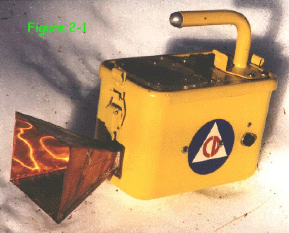
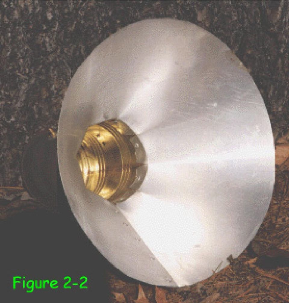
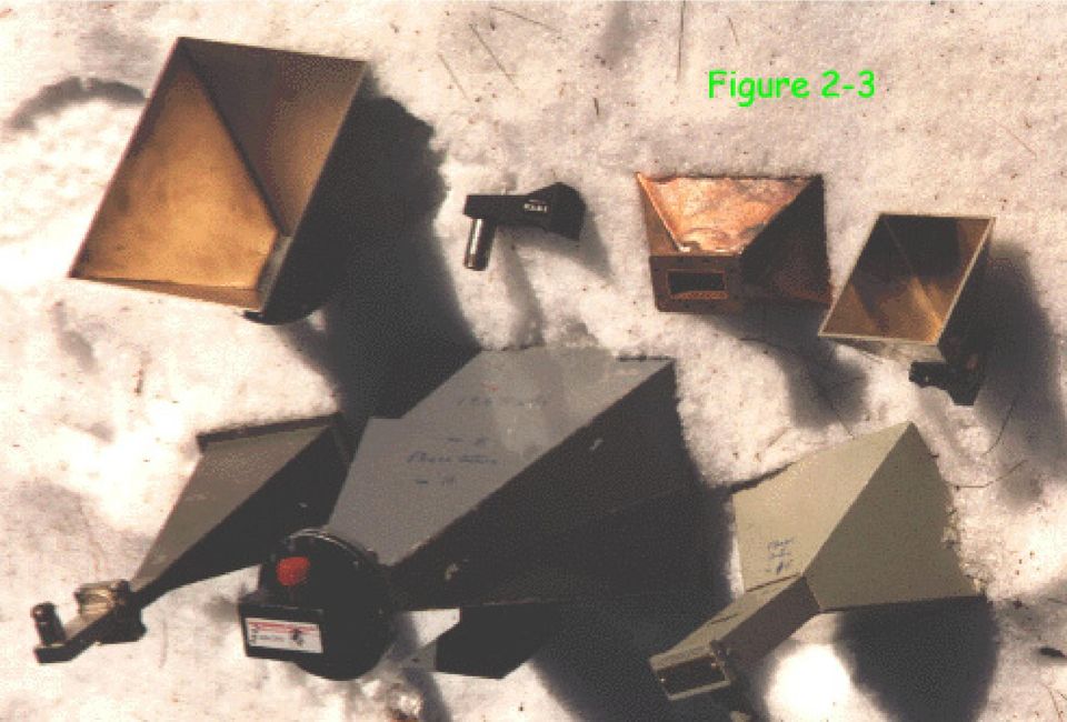
1 Chapter 2 ELECTROMAGNETIC HORN ANTENNAS Paul Wade N1BWT 1994,1998 A horn antenna is the ideal choice for a rover station. It offers moderate gain in a small, rugged package with no adjustments needed, and has a wide enough beam to be easily pointed under adverse conditions. Figure 2-1 is a photograph of a homebrew horn mounted on an old Geiger counter case which houses the rest of a 10 GHz WBFM transceiver. I have worked six grid squares on 10 GHz from Mt. Wachusett in Massachusetts using only a small horn with 17.5 db gain. Horn Design An antenna may be considered as a transformer from the impedance of a transmission line to the impedance of free space, 377 ohms. A common microwave transmission line is waveguide 1, a hollow pipe carrying an electromagnetic wave. If one dimension of the pipe is greater than a half wavelength, then the wave can propagate through the waveguide with extremely low loss. And if the end of a waveguide is simply left open, the wave will radiate out from the open end. Practical waveguides have the larger dimension greater than a half wavelength, to allow wave propagation, but smaller than a wavelength, to suppress higher-order modes which can interfere with low-loss transmission. Thus the aperture of an open-ended waveguide is less than a wavelength, which does not provide much gain. For more gain, a larger aperture is desirable, but a larger waveguide is not. However, if the waveguide size is slowly expanded, or tapered, into a larger aperture, then more gain is achieved while preventing undesired modes from reaching the waveguide. To achieve maximum gain for a given aperture size and thus maximum efficiency, the taper must be long enough so that the phase of the wave is nearly constant across the aperture. In cylindrical waveguide, a funnel-like taper is called a conical horn. The conical horn for 2304 MHz shown in Figure 2-2 was made by pop-rivetting aluminum flashing to a coffee can. In common rectangular waveguide, the taper creates a familiar pyramidal horn, like those shown in the photograph, Figure 2-3. Pyramidal Horns An optimum horn is the shortest one that approaches maximum gain; several definitions are available. The HDL_ANT program uses approximate dimensions from a set of tables 2 by Cozzens to design pyramidal horn antennas with gains from 10 to 25 db. Higher gains are possible, but the length of the horn increases much faster than the gain, so very high gain horns tend to be unwieldy.

2
3
4 For pyramidal horns, Kraus 3 gives the following approximations for 3 db beam width in degrees and db gain over a dipole: Eplane = Hplane = 56 Aeλ 67 Ahλ degrees degrees and for gain G 10log10( 4.5A eλ Ahλ ) db over dipole where Aeλ is the aperture dimension in wavelengths in the E-plane and Ahλ is the aperture in wavelengths dimension in the H-plane. The HDL_ANT program uses a more accurate gain algorithm 4 which corrects the phase error of different taper lengths; for a given aperture, efficiency and gain decrease as the taper is shortened. For some applications, the beamwidth at power levels other than 3 db down is useful. For instance, the feed for a parabolic dish is often specified as having a pattern which is 10 db down at the edge of the dish. For a simple horn, the 10 db beamwidth is roughly 1.8 times the 3dB beamwidth. Other points in the main beam may be approximated using Kelleher s 5 universal horn patterns: 2 θ PdB( θ) 10 θ10 where PdB( θ ) is the relative power at angle θ from the center of the beam, andθ 10 is the angle where the power is 10 db down from maximum. Conical Horns For conical horns, an optimum horn is one which provides the desired gain with the minimum amount of material. The HDL_ANT program uses an algorithm from Jasik 6 to design optimum conical horn antennas with gains between 10 and 25 db. Again, higher gains are possible, but probably unwieldy. The HDL_ANT program will calculate gain for conical horns of any dimension, using another algorithm from Jasik 7.

5
6 Horn Construction If you are fortunate enough to find a suitable surplus horn, then this section is unnecessary. Otherwise, you may want to homebrew one. Horn fabrication is quite simple, so we can homebrew them as needed, for primary antennas with moderate gain or as feeds for higher gain dishes and lenses. Performance of the finished horn almost always matches predictions, with no tuning adjustments required. The HDL_ANT program will design a horn with any desired gain or physical dimensions and then make a template for the horn. The template is a PostScript TM file; print the file on a computer printer (see Appendix 1 for details on printing a PostScript file) to generate a paper template, tape the paper template to a sheet of copper or brass, and cut it out. If the template is for a pyramidal horn, fold on the dotted lines, and solder the metal horn together on the end of a waveguide. The horn shown in Figure 2-1 used flashing copper from the local lumberyard, which I soldered together on the kitchen stove. Figure 2-4 is a template for a nominal 14 db horn for 5760 MHz generated by HDL_ANT. Try it: copy it on a copier and fold up the copy to see how easy it is to make a horn. It's almost as easy with thin copper. Figure 2-5 is another template example, a nominal 18 db horn for MHz. For horns too large to fit the entire template on one sheet of paper, HDL_ANT prints each side on a separate sheet. Templates for conical horns are even simpler: just two concentric sections of a circle, like Figure 2-6, a nominal 14 db horn for MHz. When the two straight edges are joined together, a cone is formed. In metal, we solder the two edges together and then solder it to the cylindrical waveguide. For cylindrical horns too large to fit the entire template on one sheet of paper, HDL_ANT displays the dimensions necessary to do layout with a compass and straightedge. Feed Horns For horns intended as feed horns for dishes and lenses, beam angle and phase center are more important than horn gain. For pyramidal horns, the HDL_ANT program calculates these values in both the E-plane and the H-plane, then allows you to enter new horn dimensions to adjust the beam angle or phase center before making a template. The phase center calculation is a difficult one 6 involving Fresnel sines and cosines 8, so interactive adjustment of horn dimensions is a lot easier than having the computer try to find the right dimensions. The template in Figure 2-7 is one example of a feed horn it may be used to make a rectangular horn optimized to feed a dish 9 with f/d = 0.5 at 10 GHz. Feed horn design for dishes and lenses will be described in more detail later.

7 Figure 2-4. Template for dbi horn for 5760 MHz E-plane N1BWT 1994 inch 2 mm

8 Figure 2-5. Template for dbi horn for MHz E-plane N1BWT 1994 inch 2 mm

9 Figure 2-6. Template for 14 dbi conical horn for MHz N1BWT 1998 inch 2 mm

10 Figure 2-7. Template for 8.05 dbi horn for MHz E-plane N1BWT 1994 inch 2 mm Figure 2-7. Feedhorn Template

11 Conclusion Horns are versatile microwave antennas, easy to design and build with predictable performance. They should be the antenna of choice for all but the highest gain applications. References 1. The ARRL UHF/Microwave Experimenter's Manual, ARRL, 1990, pp to D.E. Cozzens, "Tables Ease Horn Design," Microwaves, March 1966, pp John Kraus (W8JK), Antennas, McGraw Hill, C.A. Balanis, "Horn Antennas," in Antenna Handbook: theory, applications, and design, Y.T. Lo and S.W. Lee, editors, Van Nostrand Reinhold, 1988, page C.M. Knop & H.J. Wiesenforth, On the Ratiation from an Open-Ended Corrugated Pipe Carrying the HE 11 Mode, IEEE Transactions on Antennas and Propagation, Sept. 1972, pp H. Jasik, Antenna Engineering Handbook, First Edition, Mcgraw-Hill, 1961, p Eugen I Muehldorf, The Phase Center of Horn Antennas," reprinted in A. W. Love, Electromagnetic Horn Antennas, IEEE Press, Milton Abramowitz and Irene A. Stegun, Handbook of Mathematical Functions, Dover, D. Evans, G3RPE, "Pyramidal horn feeds for paraboloidal dishes," Radio Communication, March 1975.

Chapter 1 ANTENNA FUNDAMENTALS. Paul Wade W1GHZ (ex-n1bwt) 1994,1997,1998 ANTENNA BASICS
 1994,1997,1998 ANTENNA BASICS") Chapter 1 ANTENNA FUNDAMENTALS Paul Wade W1GHZ (ex-n1bwt) 1994,1997,1998 Introduction Antenna gain is essential for microwave communication since it helps both transmitting and receiving, it is doubly
Chapter 1 ANTENNA FUNDAMENTALS Paul Wade W1GHZ (ex-n1bwt) 1994,1997,1998 Introduction Antenna gain is essential for microwave communication since it helps both transmitting and receiving, it is doubly
Chapter 3 METAL-PLATE LENS ANTENNAS Paul Wade N1BWT 1994,1998
 Chapter 3 METAL-PLATE LENS ANTENNAS Paul Wade N1BWT 1994,1998 Introduction For portable microwave operation, particularly if backpacking is necessary, dishes or large horns may be heavy and bulky to carry.
Chapter 11 PARABOLIC DISH FEEDS PERFORMANCE ANALYSIS Paul Wade N1BWT 1997,1998
 Chapter 11 PARABOLIC DISH FEEDS PERFORMANCE ANALYSIS Paul Wade N1BWT 1997,1998 Achieving optimum performance from a microwave dish antenna requires that the feed antenna be matched to the parabolic reflector.
Pillbox Antenna for 5.6 GHz Band Dragoslav Dobričić, YU1AW [email protected]
 Pillbox Antenna for 5.6 GHz Band Dragoslav Dobričić, YU1AW [email protected] Introduction The pillbox or cheese antenna is made of two parallel plates which are connected to the narrow strip of parabolic
Antenna Glossary Before we talk about specific antennas, there are a few common terms that must be defined and explained:
 Antenna Basics Introduction Antennas are a very important component of communication systems. By definition, an antenna is a device used to transform an RF signal, traveling on a conductor, into an electromagnetic
Chapter 4 PARABOLIC DISH ANTENNAS Paul Wade N1BWT 1994,1998
 Chapter 4 PARABOLIC DISH ANTENNAS Paul Wade N1BWT 1994,1998 Introduction Parabolic dish antennas can provide extremely high gains at microwave frequencies. A 2- foot dish at 10 GHz can provide more than
WAVEGUIDE-COAXIAL LINE TRANSITIONS
 WAVEGUIDE-COAXIAL LINE TRANSITIONS 1. Overview Equipment at microwave frequencies is usually based on a combination of PCB and waveguide components. Filters and antennas often use waveguide techniques,
Analysis of the G3LTF Dual Band Feed for 23cm and 13cm Paul Wade W1GHZ 2004 [email protected]
 Analysis of the G3LTF Dual Band Feed for 23cm and 13cm Paul Wade W1GHZ 2004 [email protected] In the March 2004 edition of the RSGB Microwave Newsletter, G3LTF described 1 a dual band feed for the 23 cm and
New Method for Optimum Design of Pyramidal Horn Antennas
 66 New Method for Optimum Design of Pyramidal Horn Antennas Leandro de Paula Santos Pereira, Marco Antonio Brasil Terada Antenna Group, Electrical Engineering Dept., University of Brasilia - DF [email protected]
Design of a Planar Omnidirectional Antenna for Wireless Applications
 Design of a Planar Omnidirectional Antenna for Wireless Applications Randy Bancroft and Blaine Bateman Centurion Wireless Technologies Westminster, Colorado Abstract Omnidirectional antennas are of great
Paul Wade, W1GHZ. 161 Center Rd Shirley, MA 01464 [email protected]. Figure 1 WR-75 waveguide to coax transition for 10 GHz. 1 Notes appear on page 16.
 Rectangular Waveguide to Coax Transition Design Learn how to find the optimum dimensions for a waveguide to coax transition using an empirical approach that relies on a set of impedance measurements and
Design & Simulation of 8-Shape Slotted Microstrip Patch Antenna
 World Applied Sciences Journal 31 (6): 1065-1071, 2014 ISSN 1818-4952 IDOSI Publications, 2014 DOI: 10.5829/idosi.wasj.2014.31.06.1462 Design & Simulation of 8-Shape Slotted Microstrip Patch Antenna Sohag
Design and Electromagnetic Modeling of E-Plane Sectoral Horn Antenna For Ultra Wide Band Applications On WR-137 & WR- 62 Waveguides
 International Journal of Engineering Science Invention ISSN (Online): 2319 6734, ISSN (Print): 2319 6726 Volume 3 Issue 7ǁ July 2014 ǁ PP.11-17 Design and Electromagnetic Modeling of E-Plane Sectoral Horn
Antenna Basic Concepts
 ANTENNA An antenna is a device to transmit and/or receive electromagnetic waves. Electromagnetic waves are often referred to as radio waves. Most antennas are resonant devices, which operate efficiently
W1GHZ W1GHZ W1GHZ W1GHZ W1GHZ W1GHZ W1GHZ W1GHZ
 Online Online Online Online Online Online Online Antenna Book Antenna BookOnline Antenna Book Antenna Book Antenna Book Antenna Book Antenna Book Antenna Book Chapter 7 Slot Antennas Paul Wade 2000,2001
Review Paper for Broadband CPW-Fed T-Shape Slot Antenna
 Review Paper for Broadband CPW-Fed T-Shape Slot Antenna Shahpure Sana 1, Bharate Rajashri 2, Prof. Jadhav D.A. 3 1,2 BE, Dept. of E&TC, Brahmdevdada Mane Institute of Technology, Dist. Solapur (Maharashtra)
Basic Antenna Theory and Application
 Project Number: SNM MQP 0414 Basic Antenna Theory and Application A Major Qualifying Project Report: Submitted to the Faculty of the WORCESTER POLYTECHNIC INSTITUTE in partial fulfillment of the requirements
An octave bandwidth dipole antenna
 An octave bandwidth dipole antenna Abstract: Achieving wideband performance from resonant structures is challenging because their radiation properties and impedance characteristics are usually sensitive
Rec. ITU-R F.699-5 1 RECOMMENDATION ITU-R F.699-5 *
 Rec. ITU-R F.699-5 1 RECOMMENATION ITU-R F.699-5 * REFERENCE RAIATION PATTERNS FOR LINE-OF-SIGHT RAIO-RELAY SYSTEM ANTENNAS FOR USE IN COORINATION STUIES AN INTERFERENCE ASSESSMENT IN THE FREQUENCY RANGE
A DUAL-POLARIZED WIDE-BAND PATCH ANTENNA FOR INDOOR MOBILE COMMUNICATION APPLICA- TIONS
 Progress In Electromagnetics Research, PIER 1, 189 2, 2010 A DUAL-POLARIZED WIDE-BAND PATCH ANTENNA FOR INDOOR MOBILE COMMUNICATION APPLICA- TIONS M. Secmen and A. Hizal Department of Electrical and Electronics
Selecting Receiving Antennas for Radio Tracking
 Selecting Receiving Antennas for Radio Tracking Larry B Kuechle, Advanced Telemetry Systems, Inc. Isanti, Minnesota 55040 [email protected] The receiving antenna is an integral part of any radio location
Wireless RF Distribution in Buildings using Heating and Ventilation Ducts
 Wireless RF Distribution in Buildings using Heating and Ventilation Ducts Christopher P. Diehl, Benjamin E. Henty, Nikhil Kanodia, and Daniel D. Stancil Department of Electrical and Computer Engineering
Applications in EMC testing. Outline. Antennas for EMC Testing. Terminology
 Antennas for EMC Testing Zhong Chen ETS-Lindgren 1301 Arrow Point Drive Cedar Park, TX 78613 [email protected] Outline EMC Terms and Definitions Typical EMC Antennas Calibration of EMC Antennas
Helical Feed Antennas Paul Wade W1GHZ 2002 [email protected]
 Helical Feed Antennas Paul Wade W1GHZ 22 [email protected] Helical antennas have long been popular in applications from VHF to microwaves requiring circular polarization, since they have the unique property
Antenna Trainer EAN. www.edibon.com. Technical Teaching Equipment INTRODUCTION
 Antenna Trainer EAN Technical Teaching Equipment Products Products range Units 3.-Communications INTRODUCTION Antennas are the main element of aerial communications. They are the transition between a transmission
5. ANTENNA TYPES. Figure 5. The vertical dipole and its electromagnetic equivalent, the vertical monopole
 Antennas can be classified in several ways. One way is the frequency band of operation. Others include physical structure and electrical/electromagnetic design. The antennas commonly used for LMR both
BROADBAND ARRAY ANTENNA
 BROADBAND ARRAY ANTENNA Mike Stasiowski Cobham Defense Electronic Systems Nurad Division 3310 Carlins Park Drive Baltimore, MD 21215 Dan Schaubert Antennas and Propagation Laboratory Electrical and Computer
You will need the following pieces of equipment to complete this experiment:
 UNIVERSITY OF TORONTO FACULTY OF APPLIED SCIENCE AND ENGINEERING The Edward S. Rogers Sr. Department of Electrical and Computer Engineering ECE422H1S: RADIO AND MICROWAVE WIRELESS SYSTEMS EXPERIMENT 3:
Designing Log Periodic Antennas
 Designing Log Periodic Antennas By Glen Dash, Ampyx LLC, GlenDash at alum.mit.edu Copyright 2000, 2005 Ampyx LLC Lightweight and precise, the log periodic has become a favorite among EMC engineers. In
Chapter 9 ANTENNA RANGE MEASUREMENTS Paul Wade N1BWT 1994,1998
 Chapter 9 ANTENNA RANGE MEASUREMENTS Paul Wade N1BWT 1994,1998 Hams have been measuring antennas for many years at VHF and UHF frequencies, and have seen marked improvement in antenna designs and performance
Efficient 2 meter Disguise Antenna Made From a TV Satellite Dish
 Efficient 2 meter Disguise Antenna Made From a TV Satellite Dish This horizontal slot antenna, cut into the reflector of a TV dish, is both the master of disguise and high in performance. By John Portune
How To Simulate An Antenna On A Computer Or Cell Phone
 1 Antennas Complete Technology for Antenna Simulation Edoardo Genovese, CST AG [email protected] www.cst.com CST workshop series 2010 February 10 1 About CST founded in 1992 160 employees world-wide
A Novel Multi Frequency Rectangular Microstrip Antenna with Dual T Shaped Slots for UWB Applications
 IOSR Journal of Electronics and Communication Engineering (IOSR-JECE) e-issn: 2278-2834,p- ISSN: 2278-8735.Volume 9, Issue 1, Ver. VI (Feb. 2014), PP 120-124 A Novel Multi Frequency Rectangular Microstrip
Antenna Deployment Technical Brief
 ProCurve Networking Antenna Deployment Technical Brief Introduction... 2 Antenna types... 2 Omni directional antennas... 2 Directional antennas... 2 Diversity antennas... 3 High gain directional antennas...
International Journal of Computer Trends and Technology (IJCTT) volume 4 Issue 9 Sep 2013
 volume 4 Issue 9 Sep 2013") Design and Development of Tapered Spiral Helix Antenna B.Sai Yashodha #1, J.Ravindranadh *2 1 # Mtech Student, ECE Department, RVR&JCCE, GUNTUR 2 # Associate Professor, ECE Department, RVR&JCCE, GUNTUR
Design and Development of Tapered Spiral Helix Antenna B.Sai Yashodha #1, J.Ravindranadh *2 1 # Mtech Student, ECE Department, RVR&JCCE, GUNTUR 2 # Associate Professor, ECE Department, RVR&JCCE, GUNTUR
Quad-Band U-Slot Antenna for Mobile Applications
 22 E. HERAS, Z. RAIDA, R. LAMADRID, QUAD-BAND U-SLOT ANTENNA FOR MOBILE APPLICATIONS Quad-Band U-Slot Antenna for Mobile Applications Eduardo de las HERAS PALMERO, Zbyněk RAIDA, Roberto LAMADRID RUIZ Dept.
RFID Receiver Antenna Project for 13.56 Mhz Band
 RFID Receiver Antenna Project for 13.56 Mhz Band Fatih Eken TE 401 Microwave Course Term Project, Fall 2004 Supervised by Asst. Prof. İbrahim Tekin Telecommunication Program in Faculty of Engineering and
2/20/2009 3 Transmission Lines and Waveguides.doc 1/3. and Waveguides. Transmission Line A two conductor structure that can support a TEM wave.
 2/20/2009 3 Transmission Lines and Waveguides.doc 1/3 Chapter 3 Transmission Lines and Waveguides First, some definitions: Transmission Line A two conductor structure that can support a TEM wave. Waveguide
LOW GAIN BASE STATION ANTENNA AV1312-1A
 SPECIALS : AV1312-1A LOW GAIN BASE STATION ANTENNA AV1312-1A AV1312-1A 118 144 MHz 26 MHz 50 Ω DC grounded 1,5 max/depending on mounting 2 dbi E-plane 3 db beamwidth 70 H-plane 3 db beamwidth 200 /depending
Various Technics of Liquids and Solids Level Measurements. (Part 3)
") (Part 3) In part one of this series of articles, level measurement using a floating system was discusses and the instruments were recommended for each application. In the second part of these articles,
(Part 3) In part one of this series of articles, level measurement using a floating system was discusses and the instruments were recommended for each application. In the second part of these articles,
Connected U-Slots Patch Antenna for WiMAX Applications
 Connected U-Slots Patch Antenna for WiMAX Applications Hattan F. AbuTarboush (1), D. Budimir (2), R. Nilavalan (1) and H. S. Al-Raweshidy (1) (1) Wireless Network and Communication Centre (WNCC), School
A Dual-Band Beam-Switched Slot Array for GSM 900/1800MHz
 Proceedings of Asia-Pacific Microwave Conference 2006 A Dual-Band Beam-Switched Slot Array for GSM 900/1800MHz Yijun Liu, Zhongxiang Shen, Boyu Zheng and Weihua Tan School of Electrical and Electronic
Proposal for a Slot Pair Array Having an Invariant Main Beam Direction with a Cosecant Radiation Pattern Using a Post-Wall Waveguide
 176 IEICE TRANS. ELECTRON., VOL.E86 C, NO.2 FEBRUARY 2003 PAPER Special Issue on Circuit and Device Technology for High-Speed Wireless Communication Proposal for a Slot Pair Array Having an Invariant Main
EE302 Lesson 14: Antennas
 EE302 Lesson 14: Antennas Loaded antennas /4 antennas are desirable because their impedance is purely resistive. At low frequencies, full /4 antennas are sometime impractical (especially in mobile applications).
National Laboratory of Antennas and Microwave Technology Xidian University Xi an, Shaanxi 710071, China
 Progress In Electromagnetics Research, PIER 76, 237 242, 2007 A BROADBAND CPW-FED T-SHAPE SLOT ANTENNA J.-J. Jiao, G. Zhao, F.-S. Zhang, H.-W. Yuan, and Y.-C. Jiao National Laboratory of Antennas and Microwave
Antenna Measurement 1 Antenna Ranges antenna range
 Antenna Measurement 1 Antenna Ranges An antenna range is a facility where antenna radiation characteristics are measured. An antenna range includes the following typical components: 1. A substantial space
Modeling an 80/40/20M Fan Dipole for DX
 Modeling an 80/40/20M Fan Dipole for DX New Station New Antennas! Installation and SWR Response Where is the DX? How do these Dipoles Play? (EZNEC) What about Terrain? HFTA and Terrain The effect on these
Antenna Properties and their impact on Wireless System Performance. Dr. Steven R. Best. Cushcraft Corporation 48 Perimeter Road Manchester, NH 03013
 Antenna Properties and their impact on Wireless System Performance Dr. Steven R. Best Cushcraft Corporation 48 Perimeter Road Manchester, NH 03013 Phone (603) 627-7877 FAX: (603) 627-1764 Email: [email protected]
Connectivity in a Wireless World. Cables Connectors 2014. A Special Supplement to
 Connectivity in a Wireless World Cables Connectors 204 A Special Supplement to Signal Launch Methods for RF/Microwave PCBs John Coonrod Rogers Corp., Chandler, AZ COAX CABLE MICROSTRIP TRANSMISSION LINE
Franz Hirtenfelder and Stephen Murray, CST Computer Simulation Technology and W. L. Gore and Associates (Gore) March 5, 2015
 March 5, 2015") 1 of 7 3/17/2015 9:38 AM Home Franz Hirtenfelder and Stephen Murray, CST Computer Simulation Technology and W. L. Gore and Associates (Gore) March 5, 2015 Editor s Note: A cable that leaks electromagnetic
1 of 7 3/17/2015 9:38 AM Home Franz Hirtenfelder and Stephen Murray, CST Computer Simulation Technology and W. L. Gore and Associates (Gore) March 5, 2015 Editor s Note: A cable that leaks electromagnetic
COURSE TITLE Antennas and Electromagnetic Compatibility (ACEM) 1.1. Course area
 1.1. Course area") COURSE TITLE Antennas and Electromagnetic Compatibility (ACEM) 1.1. Course area Transmission Systems 1.2. Year 4º 1.3. Semester 2º 1.4. Faculty data Please add @uam.es to e-mail address below. Coordinator:
COURSE TITLE Antennas and Electromagnetic Compatibility (ACEM) 1.1. Course area Transmission Systems 1.2. Year 4º 1.3. Semester 2º 1.4. Faculty data Please add @uam.es to e-mail address below. Coordinator:
Cables and Connectors. PRINCIPLES OF LEAKY FEEDER ANTENNAS Franz Hirtenfelder and Stephen Murray
 Cables and Connectors Invited Papers From CST Computer Simulation Technology & W. L. Gore and Associates (Gore) Leaky Cables Make Fine Broadband Antennas Editor s Note: A cable that leaks electromagnetic
Cisco Integrated 4G Low-profile Outdoor Saucer Antenna (ANT-4G-SR-OUT-TNC)
") CHAPTER 10 Cisco Integrated 4G Low-profile Outdoor Saucer Antenna (ANT-4G-SR-OUT-TNC) This document describes the Cisco Integrated 4G Low-profile Outdoor Saucer Antenna that is supported on the Cisco CGR
CHAPTER 10 Cisco Integrated 4G Low-profile Outdoor Saucer Antenna (ANT-4G-SR-OUT-TNC) This document describes the Cisco Integrated 4G Low-profile Outdoor Saucer Antenna that is supported on the Cisco CGR
Antennas 101 The Basics. Ward Silver NØAX
 Antennas 101 The Basics Ward Silver NØAX The Basics - 1 Antennas radiate (or receive) because electrons are accelerated (or are caused to accelerate) in the antenna s elements Radio or electromagnetic
APPLICATION NOTE AP050830
 APPLICATION NOTE AP050830 Selection and use of Ultrasonic Ceramic Transducers Pro-Wave Electronics Corp. E-mail: [email protected] URL: http://www.prowave.com.tw The purpose of this application note
AVR2006: Design and characterization of the Radio Controller Board's 2.4GHz PCB Antenna. Application Note. Features.
 AVR26: Design and characterization of the Radio Controller Board's 2.4GHz PCB Antenna Features Radiation pattern Impedance measurements WIPL design files NEC model Application Note 1 Introduction This
Copyright 1996 IEEE. Reprinted from IEEE MTT-S International Microwave Symposium 1996
 Copyright 1996 IEEE Reprinted from IEEE MTT-S International Microwave Symposium 1996 This material is posted here with permission of the IEEE. Such permission of the IEEE does not in any way imply IEEE
MINIMUM USAGE OF FERRITE TILES IN ANECHOIC CHAMBERS
 Progress In Electromagnetics Research B, Vol. 19, 367 383, 2010 MINIMUM USAGE OF FERRITE TILES IN ANECHOIC CHAMBERS S. M. J. Razavi, M. Khalaj-Amirhosseini, and A. Cheldavi College of Electrical Engineering
1 Numerical Electromagnetics Code (NEC)
") Wire Antenna Modelling with NEC-2 1 Numerical Electromagnetics Code (NEC) The software Numerical Electromagnetics Code (NEC-2) has been developed in the 1970s in the Lawrence Livermore Laboratory in Livermore,
Wire Antenna Modelling with NEC-2 1 Numerical Electromagnetics Code (NEC) The software Numerical Electromagnetics Code (NEC-2) has been developed in the 1970s in the Lawrence Livermore Laboratory in Livermore,
Large Dish Cassegrain Development Using CAD & Spreadsheet For Millimetric Bands & Practical Implementation.
 Large Dish Cassegrain Development Using CAD & Spreadsheet For Millimetric Bands & Practical Implementation. Martin Farmer G7MRF Email: [email protected] August 14, 2000 Introduction The scope of this
Small Dishes for Portable 1296 EME by Allen Katz, K2UYH
 Small Dishes for Portable 1296 EME by Allen Katz, K2UYH Abstract: There is growing interest in 1296 EME dxpeditions. This paper discusses two light weight stress dish designs that have sufficient gain
A PRACTICAL MINIATURIZED U-SLOT PATCH ANTENNA WITH ENHANCED BANDWIDTH
 Progress In Electromagnetics Research B, Vol. 3, 47 62, 2008 A PRACTICAL MINIATURIZED U-SLOT PATCH ANTENNA WITH ENHANCED BANDWIDTH G. F. Khodaei, J. Nourinia, and C. Ghobadi Electrical Engineering Department
Understanding Range for RF Devices
 Understanding Range for RF Devices October 2012 White Paper Understanding how environmental factors can affect range is one of the key aspects to deploying a radio frequency (RF) solution. This paper will
LECTURE 18: Horn Antennas (Rectangular horn antennas. Circular apertures.)
") LCTUR 18: Horn Antennas (Rectangular horn antennas. Circular apertures.) 1 Rectangular Horn Antennas Horn antennas are popular in the microwave band (above 1 GHz). Horns provide high gain, low VSWR (with
LCTUR 18: Horn Antennas (Rectangular horn antennas. Circular apertures.) 1 Rectangular Horn Antennas Horn antennas are popular in the microwave band (above 1 GHz). Horns provide high gain, low VSWR (with
SIW 2D PLANAR ARRAY WITH FOUR CROSS SLOTS RADIATOR AND TUNING VIAS
 Progress In Electromagnetics Research C, Vol. 40, 83 92, 2013 SIW 2D PLANAR ARRAY WITH FOUR CROSS SLOTS RADIATOR AND TUNING VIAS P. Sanchez-Olivares, J. L. Masa-Campos *, J. A. Ruiz-Cruz, and B. Taha-Ahmed
Signal directionality Lower frequency signals are omnidirectional Higher frequency signals can be focused in a directional beam
 Transmission Media Transmission medium Physical path between transmitter and receiver May be guided (wired) or unguided (wireless) Communication achieved by using em waves Characteristics and quality of
TWO-PORT ANTENNA WITH HIGH ISOLATION FOR DTV/GSM/UMTS INDOOR APPLICATIONS
 Progress In Electromagnetics Research Letters, Vol. 10, 107 113, 2009 TWO-PORT ANTENNA WITH HIGH ISOLATION FOR DTV/GSM/UMTS INDOOR APPLICATIONS S.-G. Zhou, B.-H. Sun, Y.-F. Wei, and Q.-Z. Liu National
Analysis of Radiation Patterns of Log-Periodic Dipole Array Using Transmission Line Matrix Model
 Analysis of Radiation Patterns of Log-Periodic Dipole Array Using Transmission Line Matrix Model Surender Daasari 1, Suresh Thallapelli 2 Department of ECE, Kamala Institute of Technlogy & Science, Singapuram,
ASTRA 3B HORN ANTENNA DESIGN
 ASTRA 3B HORN ANTENNA DESIGN Jorge Teniente and Carlos del-río Grupo de Antenas, Universidad Pública de Navarra, Campus Arrosadía s/n, 31006 Spain, Email: [email protected], [email protected]
RADIATION PATTERNS. The half-power (-3 db) beamwidth is a measure of the directivity of the antenna.
 beamwidth is a measure of the directivity of the antenna.") RADIATION PATTERNS The radiation pattern is a graphical depiction of the relative field strength transmitted from or received by the antenna. Antenna radiation patterns are taken at one frequency, one
RADIATION PATTERNS The radiation pattern is a graphical depiction of the relative field strength transmitted from or received by the antenna. Antenna radiation patterns are taken at one frequency, one
Selecting a Transmission Line for Your Broadcast System
 Selecting a Transmission Line for Your Broadcast System Introduction This Bulletin presents the procedures broadcasters need for calculating attenuation and power handling parameters to properly design
Product Name Hexa-Band Cellular SMD Antenna GSM / CDMA / DCS / PCS / WCDMA /UMTS /HSDPA / GPRS / EDGE 800 MHz to 2200 MHz
 Anam PA.25a Specification Part No. PA.25a Product Name Anam Hexa-Band Cellular SMD Antenna GSM / CDMA / DCS / PCS / WCDMA /UMTS /HSDPA / GPRS / EDGE 800 MHz to 2200 MHz Feature High Efficiency Multi-Band
Printed Dipole Array Fed with Parallel Stripline for Ku-band Applications
 Printed Dipole Array Fed with Parallel Stripline for Ku-band Applications M. Dogan 1, 3,K. Özsoy 1, 2, and I.Tekin 1, 1 Electronics Engineering, Sabanci University, Istanbul, Turkey 2 Vestek Electronic
Modeling and Measuring the Creative Design CLP5130-2N Log Periodic Antenna
 Modeling and Measuring the Creative Design CLP5130-2N Log Periodic Antenna Whitham D. Reeve 1. Introduction A log periodic antenna is an array of dipoles with mathematically related lengths and spacings.
Abracon PTM Introduction to ANFCA Series Flexible Peel & Stick NFC Antennas
 Abracon PTM Introduction to ANFCA Series Flexible Peel & Stick NFC Antennas WWW.ABRACON.COM ANFCA Series Flexible Peel & Stick NFC Antennas Purpose To introduce ANFCA Series, Flexible Peel & Stick NFC
The W5JCK Guide to the Mathematic Equations Required for the Amateur Extra Class Exam
 The W5JCK Guide to the Mathematic Equations Required for the Amateur Extra Class Exam This document contains every question from the Extra Class (Element 4) Question Pool* that requires one or more mathematical
Circular Polarized antenna feed (For EME on 10GHz and 5.7GHz).
.") Circular Polarized antenna feed (For EME on 10GHz and 5.7GHz). Luis Cupido - CT1DMK, Willi Bauer LX1DB On more than one occasion at the EME conferences, circular polarization was agreed to be to be the
Circular Polarized antenna feed (For EME on 10GHz and 5.7GHz). Luis Cupido - CT1DMK, Willi Bauer LX1DB On more than one occasion at the EME conferences, circular polarization was agreed to be to be the
Just a Dipole. Gary Wescom N0GW July 16, 2007
 Just a Dipole Gary Wescom N0GW July 16, 2007 Often we will hear people describing their antennas as just a dipole. After all, a coax cable fed, half wavelength dipole is one of the simplest antennas to
Coaxial End-Launched and Microstrip to Partial H-Plane Waveguide Transitions
 1 Coaxial End-Launched and Microstrip to Partial H-Plane Waveguide Transitions Kevin H. Kloke, Johan Joubert, Senior Member, IEEE, and Johann W. Odendaal, Senior Member, IEEE Abstract Conventional rectangular
High Frequency Ceramic Solutions
 Page 1 of 6 General Specifications - Mounting Part Number 2450AT43A100 Frequency Range 2400-2500 Mhz Peak Gain 2.0 dbi typ. (-V) Average Gain 0.5 dbi typ. (-V) 9.5 db min. Input Power Impedance Operating
Technician Licensing Class
 Technician Licensing Class Antennas Presented by Amateur Radio Technician Class Element 2 Course Presentation ELEMENT 2 SUB-ELEMENTS (Groupings) About Ham Radio Call Signs Control Mind the Rules Tech Frequencies
Radio Frequency Exposure Test Report
 Radio Frequency Exposure EN 62311 January 2008 Assessment of electronic and electrical equipment related to human exposure restrictions for electromagnetic fields (0Hz 300GHz) (IEC 62311:2007, modified)
Electromagnetic radiation exposure: assessment against ACA mandated limits
 Electromagnetic radiation exposure: assessment against ACA mandated limits General radio services (operating above 0 MHz) (Edition May 0) Disclaimer Unless otherwise specified, the information contained
Avaya WLAN 9100 External Antennas for use with the WAO-9122 Access Point
 Avaya WLAN 9100 External Antennas for use with the WAO-9122 Access Point Overview To optimize the overall performance of a WLAN in an outdoor deployment it is important to understand how to maximize coverage
General Information. Lower Frequency Models Custom Designs Special Flanges Narrow Band Specials VSWR. Frequency ( GHz) COMMON SPECIFICATIONS
 COMMON SPECIFICATIONS") Waveguide Adapters General Information DC - 26.5 GHz High Performance 1.15 Typical VSWR Male or Female Connectors available Choke Flange Types available -65 o C to +125 o C Operating Temperature Midwest
Waveguide Adapters General Information DC - 26.5 GHz High Performance 1.15 Typical VSWR Male or Female Connectors available Choke Flange Types available -65 o C to +125 o C Operating Temperature Midwest
Antennas & Transmission Lines
 4 Antennas & Transmission Lines The transmitter that generates the RF 1 power to drive the antenna is usually located at some distance from the antenna terminals. The connecting link between the two is
T-slot Broadband Rectangular Patch Antenna
 International Journal of Electronic and Electrical Engineering. ISSN 0974-2174 Volume 4, Number 1 (2011), pp.43-47 International Research Publication House http://www.irphouse.com T-slot Broadband Rectangular
How To Model A Terahertz Detector
 QUADERNI DELLA SOCIETÀ ITALIANA DI ELETTROMAGNETISMO, VOL. 1, N. 2 LUGLIO 2005 123 Accurate Electromagnetic Modeling of Terahertz Detectors Paolo Focardi,William R. McGrath 1 Abstract Twin slot antennas
Software package for Spherical Near-Field Far-Field Transformations with Full Probe Correction
 SNIFT Software package for Spherical Near-Field Far-Field Transformations with Full Probe Correction Historical development The theoretical background for spherical near-field antenna measurements and
Subject: Glenair MIL-PRF 24758 Conduit Surface Transfer Impedance Test
 Lothar O. Hoeft, Ph.D. Consultant, Electromagnetic Effects 5012 San Pedro Ct., NE Albuquerque, New Mexico 87109-2515 Phone: (505)-889-9705 E-mail: [email protected] 1 February 24, 2006 Subject: Glenair
A BROADBAND COAXIAL LINE FOR ELECTRICAL CHARACTERIZATIONS OF DIELECTRICS JAFER OMER SULIMAN AZZABI
 i A BROADBAND COAXIAL LINE FOR ELECTRICAL CHARACTERIZATIONS OF DIELECTRICS JAFER OMER SULIMAN AZZABI A project report submitted in partial fulfillment of the requirement for the award of the Degree of
LTCC Short Range Radar Sensor for Automotive Applications at 24 GHz
 LTCC Short Range Radar Sensor for Automotive Applications at 24 GHz P. Uhlig, C. Günner, S. Holzwarth, J. Kassner, R. Kulke, A. Lauer, M. Rittweger IMST GmbH, D-47475 Kamp-Lintfort, Germany, www.ltcc.de
APPLICATION NOTE ULTRASONIC CERAMIC TRANSDUCERS
 APPLICATION NOTE ULTRASONIC CERAMIC TRANSDUCERS Selection and use of Ultrasonic Ceramic Transducers The purpose of this application note is to aid the user in the selection and application of the Ultrasonic
Electromagnetic radiation exposure: assessment against ACA mandated limits
 Electromagnetic radiation exposure: assessment against ACA mandated limits Paging services (Edition May 2002) Disclaimer Unless otherwise specified, the information contained in these guidelines is intended
LONG RANGE ULTRA-HIGH FREQUENCY (UHF) RADIO FREQUENCY IDENTIFICATION (RFID) ANTENNA DESIGN. A Thesis. Submitted to the Faculty.
 RADIO FREQUENCY IDENTIFICATION (RFID) ANTENNA DESIGN. A Thesis. Submitted to the Faculty.") LONG RANGE ULTRA-HIGH FREQUENCY (UHF) RADIO FREQUENCY IDENTIFICATION (RFID) ANTENNA DESIGN A Thesis Submitted to the Faculty of Purdue University by Nathan D. Reynolds In Partial Fulfillment of the Requirements
LONG RANGE ULTRA-HIGH FREQUENCY (UHF) RADIO FREQUENCY IDENTIFICATION (RFID) ANTENNA DESIGN A Thesis Submitted to the Faculty of Purdue University by Nathan D. Reynolds In Partial Fulfillment of the Requirements
Tuning a Monopole Antenna Using a Network Analyzer
 11/21/11 Tuning a Monopole Antenna Using a Network Analyzer Chris Leonard Executive Summary: When designing a monopole antenna it is important to know at which frequency the antenna will be operating at.
This Antenna Basics reference guide includes basic information about antenna types, how antennas work, gain, and some installation examples.
 Antenna Basics This Antenna Basics reference guide includes basic information about antenna types, how antennas work, gain, and some installation examples. What Do Antennas Do? Antennas transmit radio
OPTICAL FIBERS INTRODUCTION
 OPTICAL FIBERS References: J. Hecht: Understanding Fiber Optics, Ch. 1-3, Prentice Hall N.J. 1999 D. R. Goff: Fiber Optic Reference Guide (2 nd ed.) Focal Press 1999 Projects in Fiber Optics (Applications
EH-20 20m antenna. By VE3RGW
 EH-20 20m antenna By VE3RGW Equivalent circuit of EH-20 (prototype 2A) antenna system. Upper cylinder Lower cylinder Ground Counter pose Phasing coil Impedance transformer and tune circuit Tune coil Feed
Diffractive Optical Elements (DOE) for FLEXPOINT Laser Modules
 for FLEXPOINT Laser Modules") With the help of DOEs it is possible to turn a simple laser dot into a variety of different beam patterns. All DOE s can be used with FLEXPOINT laser modules, either fixed to the module or removable in
With the help of DOEs it is possible to turn a simple laser dot into a variety of different beam patterns. All DOE s can be used with FLEXPOINT laser modules, either fixed to the module or removable in