TABLE-TYER / TABLE-TYER SS POWER STRAPPING MACHINES 04/12/07
|
|
|
- Dominic Hodges
- 9 years ago
- Views:
Transcription
1 TABLE-TYER / TABLE-TYER SS POWER STRAPPING MACHINES 04/12/07

2 CONGRATULATIONS Thank you for purchasing your Table-Tyer Strapping Machine. The Table-Tyer has been designed to be a reliable, maintenance free strapping machine. The innovative design of this machine allows for every maintenance part to be replaced easily and quickly with very little or no instruction. Considerable effort has been made to ensure that this product conforms to our high quality standards. However, should you experience any difficulties, please contact your Signode Representative with your machine model and serial number. Thank you for your help. 04/12/07 CONTENTS Page Safety Information 3 Specifications 5 Major Components 7 Disconnect & Lockout 9 Electrical Schematic 10 Operation 12 Parts List & Views 15 TABLE-TYER STRAPPING MACHINE PART NO Spare Parts 53 All conditions and options have been detailed in this manual to guide and alert operating and service personnel with respect to safety, operation and maintenance procedures. A complete parts listing, with exploded views, has been included in this manual in the event replacement parts must be ordered. Please review each section of this manual before operating your machine. PLEASE NOTE: Most of the fasteners in this machine are metric. Before removing and replacing any part, refer to the parts listing to determine the proper tools to use and the correct size hardware that may have to be replaced. TABLE-TYER SS STRAPPING MACHINE PART NO

3 WARNING - READ AND FOLLOW THESE INSTRUCTIONS - FAILURE TO DO THIS COULD RESULT IN SEVERE PERSONAL INJURY. OPERATING INSTRUCTIONS 1. Only people trained in the use of strapping machines are to operate or service this machine. 2. Read all signs on machine. Do not remove, modify or deface any sign. Replace all damaged signs. 3. Inspect the machine for unsafe conditions - DAILY - and replace all worn or broken parts. 4. Keep work area uncluttered and well lit. 5. If you require safety instructions in another language, contact your local Signode representative. MAINTENANCE 1. Establish a preventive maintenance program for your machine by following the preventive maintenance program in this manual. 2. To ensure proper machine operation, use the specified power sources listed in this manual. 3. Do not overload the machine by exceeding the package size specification. 4. Remove all packages from the machine before performing service. 5. Unless otherwise noted in this manual, disconnect and lockout all power before servicing your machine. 6. Follow all maintenance and service instructions in this manual. MOVING MACHINE PARTS 1. Disconnect and lock out all power to Signode's machines before entering the strap chute area. 2. Never put any part of your body into the strap chute area or machine enclosure with machine power on. 3. Never stand on the machine table-top. MACHINE INSTALLATION 1. All customer interlocks must be connected as shown in this manual's electrical drawings. Failure to properly connect interlocks can result in improper machine operation and/or personal injury. 2. Be familiar with the locations of safety interlocks/guards and Emergency Stop Devices - refer to machine manual topic "Disconnect & Lockout Procedures". 3. Do not defeat any safety interlock or safety device. Do not operate machine with any safety devices/guards removed. 4. Before operating the machine, ensure that all safety interlocks and Emergency Stop buttons are operating properly. 5. Unauthorized modifications can present a safety hazard to machine personnel and will void the machine warranty. 6. Secure the machine in place using the locking casters. 3

4 PERSONAL PROTECTION 1. To prevent back or other body injuries, your employer must provide proper lifting and/or handling instructions. Your employer may also contact the National Safety Council, Itasca, IL for information on lifting techniques. 2. When removing tensioned strap from a package, proceed as follows: a. Wear eye, face and hand protection b. Before cutting strap, make sure all personnel are at a safe distance. c. Hold the strap against the load above the cutter as shown. d. Using the proper Signode strap cutter, cut strap as pictured. e. Stand clear of unheld strap end which will spring out if under pressure. 3. Always wear steel reinforced safety shoes. 4. Always wear safety glasses with side shields which conform to ANSI Standard Z-87.1 or EN Wear protective gloves when handling strap. ENVIRONMENTAL INFORMATION The emissions produced during the heat sealing process may be an irritant to some people. Use this machine in areas that are externally ventilated. Should you be affected by these fumes, move away from machine to fresh air. LOCKOUT/TAGOUT 1. Follow OSHA (Lockout/Tagout Regulation) for machine lockout procedures and other important lockout/tagout guidelines. 2. Be familiar with all lockout sources on this machine, refer to the "Lockout & Tagout" section of this manual. 3. Even after a machine has been locked out, there may be stored energy in the system. To ensure that all stored energy is relieved, wait at least one minute before servicing electrical capacitors and wait 5 minutes for hot knife to cool. 4. Before performing service in the strap chute area, disconnect and lockout machine power. MOVING THE MACHINE Wheel kits are standard for Signode general purpose machines. A forklift may be used to transport the machine from one location to another. Consult your employer for proper lifting and handling methods. 4

5 TABLE-TYER, MACHINE SPECIFICATIONS STRAP SIZES: Signode Empax 1/4" (6mm), 3/8" (9mm), 1/2" (12mm) PACKAGE SIZE (Minimum): 2"W x 1-1/2"H when equipped with the Small Package Option VOLTAGE SPECIFICATIONS: Rated current: 3A Rated voltage: 110V Rated frequency: 6OHz Type of current: AC FAULT PROTECTION: Fused SYSTEM DISCONNECT: HP Rated switch OPERATING HEIGHT: Minimum 30-3/4", Maximum 37-1/2" WEIGHT: 168 lbs. NOISE EMISSIONS: 55dB MACHINE DIMENSIONS: 5

6 TABLE-TYER SS, MACHINE SPECIFICATIONS STRAP SIZES: Signode Empax 1/4" (6mm), 3/8" (9mm), 1/2" (12mm) PACKAGE SIZE (Minimum): 1-1/2"W x 3"H VOLTAGE SPECIFICATIONS: Rated current: 3A Rated voltage: 110V Rated frequency: 6OHz Type of current: AC FAULT PROTECTION: Fused SYSTEM DISCONNECT: HP Rated switch OPERATING HEIGHT: Minimum 15-1/2", Maximum 27-3/8" WEIGHT: 221 lbs. NOISE EMISSIONS: 65dB MACHINE DIMENSIONS: 6

7 MAJOR COMPONENTS - EXTERNAL 1. Main switch 2. Heater lamp, lamp will light on when proper sealing temperature is reached 3. Potentiometer, strap feed length 4. Button, strap feed and reset 5. Potentiometer, strap tension adjustment 6. Table top, hinge 7. Strap reel 8. Caster (2 locking) 9. Adjustable legs (Table-Tyer) Adjustable roller platform (Table-Tyer SS) 10. Frame 11. Access Door 7
 9.")
8
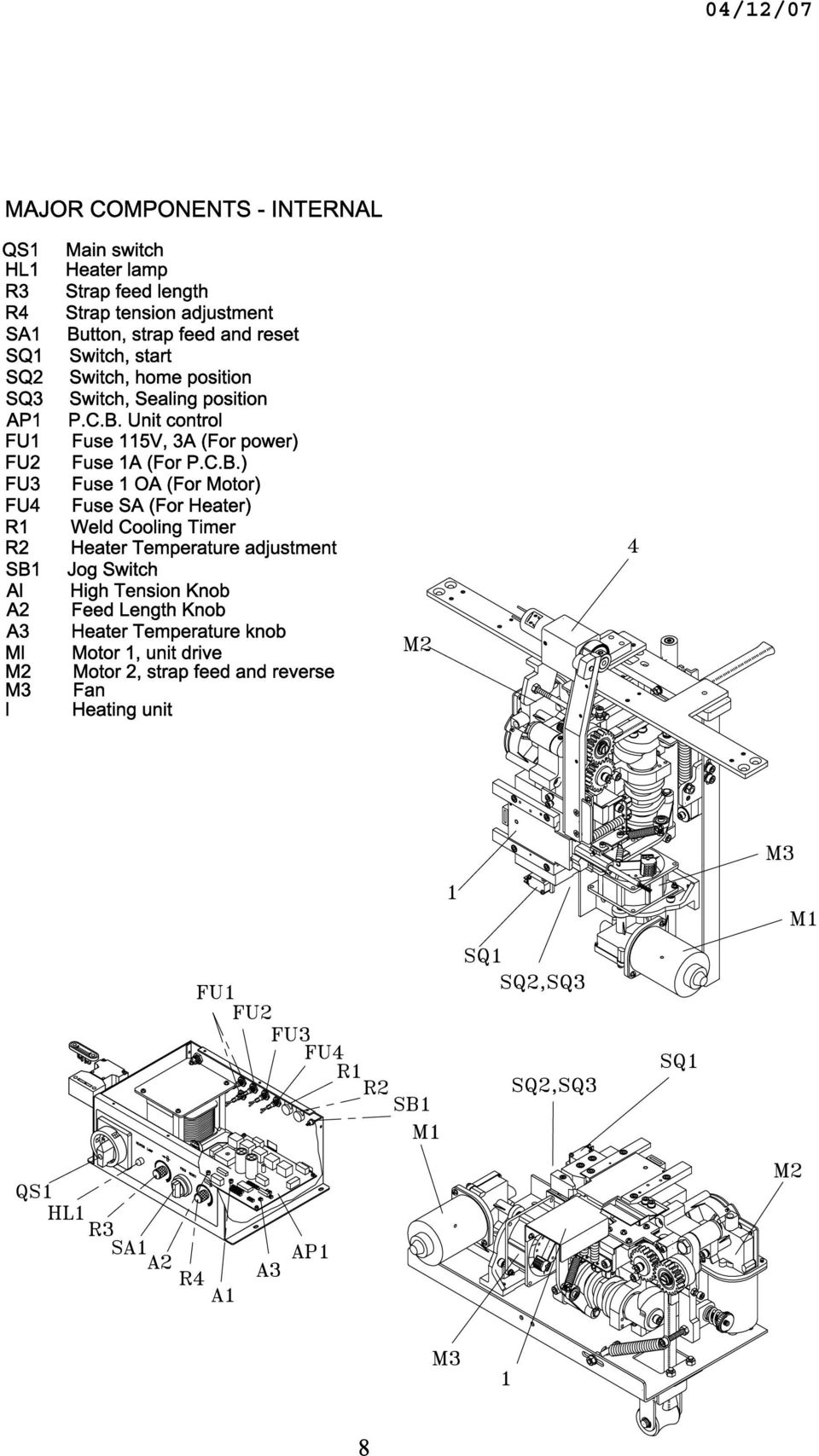
9 MACHINE DISCONNECT AND LOCK-OUT PROCEDURES This machine is equipped with shut off devices which satisfy OSHA Regulation (control of hazardous energy sources - lock out/tag out). Become familiar with the location, and operation of each shutoff device. Disconnect/Lock-Out all power sources before servicing machine. Never use machine operating controls as a means for locking out power. ELECTRICAL The machine is ready to operate when connected to the main power supply and the main switch QS I is switched to ON position. It takes approximately I minute for the heating element to reach its operating temperature. The machine is switched on and off with the main switch QS 1 located on the machine front operating panel. P P Turn the main disconnect switch to the OFF position. Locate the appropriate locking hole on the switch, and apply a locking device. NOTE: Some electrical components in the machine may be electrically charged after the power is shut off. Wait no less than one minute after the power has been disconnected before servicing the panel. 9

10 ELECTRICAL SCHEMATIC, TABLE TYER 10

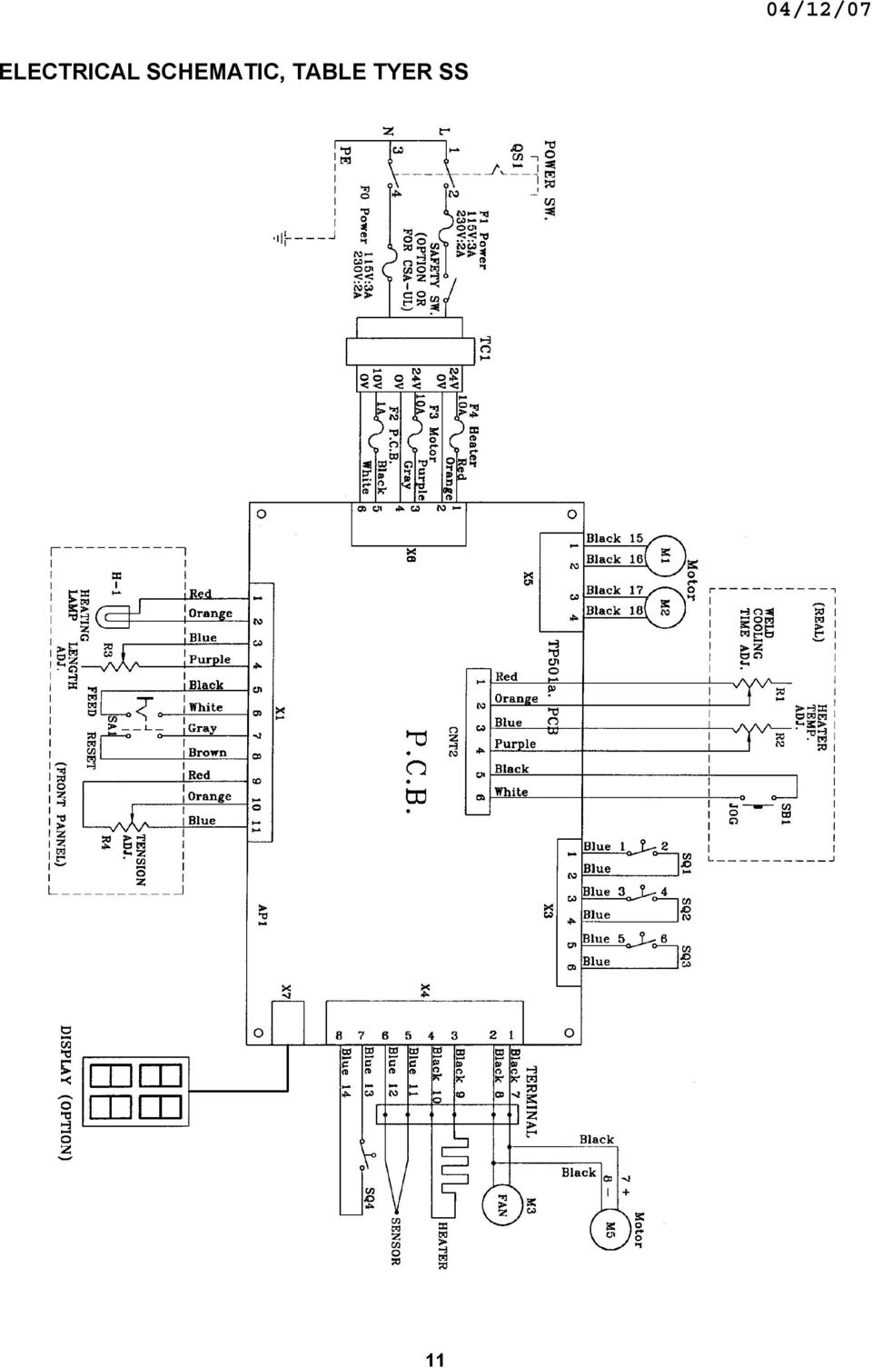
11 ELECTRICAL SCHEMATIC, TABLE TYER SS 11
12 MACHINE OPERATION START-UP AND OPERATING SEQUENCE 1. Put strap on the strap reel and thread the strap. 2. Turn main switch QS1 to ON. The heating element reaches the working temperature in approximately 1 minute. 3. Use potentiometer R3 to adjust the strap length. 4. Place the strap around the package to be strapped and insert the strap into the strapping head until it stops. 5. The strapping and welding sequence should complete. 6. At end of strapping sequence the strap end is fed automatically. 7. R4 adjusts the strap tension. THREADING STRAP 1. Turn reel nut handle (A) left and remove it. 2. Remove the cover of the reel (B) and install the strap reel. 3. Make sure that the payoff rotation matches directional arrows when unrolling. 4. Put the reel cover back on and tighten reel nut handle (A) to the right. 5. Remove all adhesive strips or other adhesive material. 6. Unroll about 1.5 m strap and make sure that it is not twisted. 7. Thread the strap in direction of arrow over (C) to roller (D). Continue to thread strap into rollers (E). 8. Turn left button SA1 (strap feed) until the length you need. 12
 left and remove it. 2.")
13 STRAP TENSION If R4 (strap tension adjustment) is on MAX position make sure that A is turned clockwise until the strap is not sliding between rollers B and C. Reverse action to achieve lower strap tension. MAINTENANCE AND LUBRICATION To ensure that the semi-automatic strapping machine is always ready for proper and reliable operation keep to regular and attentive maintenance. Keep the machine clean and take care particularly of the strap guides. All small particles of loose strap should always be removed from all parts of the machine. In addition to the strap guides, the strap feed devices of the unit, the top of the dies and the feed devices on the strap magazine have to be blown free of any dust at least once per week. The dies on the unit have to be lightly lubricated weekly. Lubricate the marked points weekly. Use only resin-free brand name oil for lubrication. All other assemblies are maintenance free. The strap guides and the sealing unit have to be kept clean! Do not oil feedrollers. 13

14 BLANK 14

15

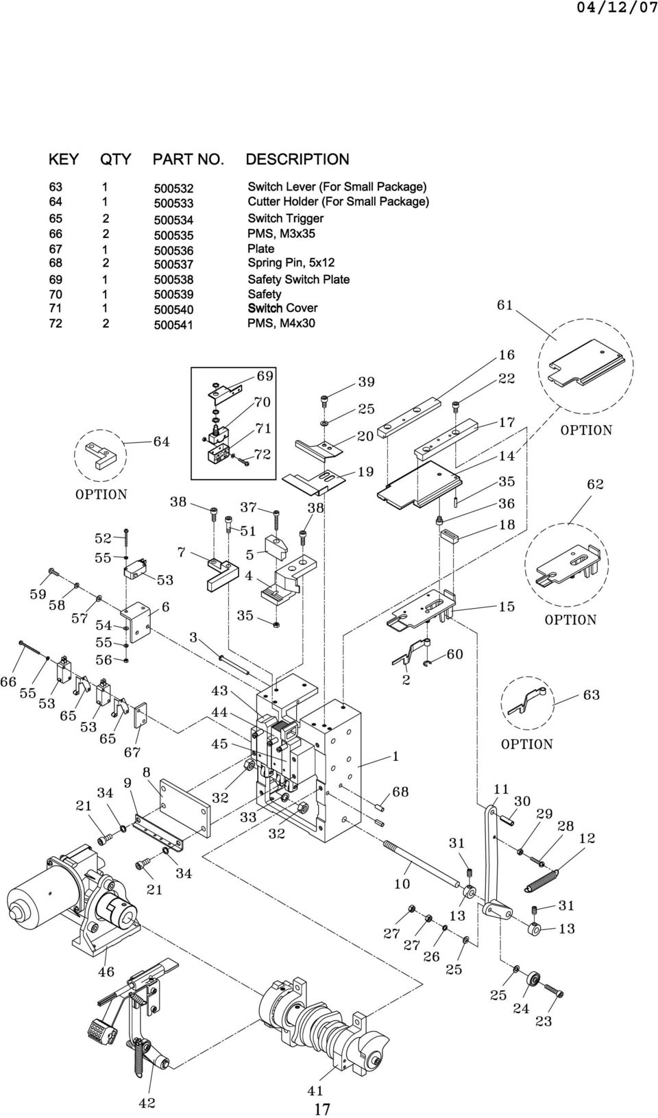
16 CONTROL HEAD GROUP ASSEMBLY KEY QTY PART NO. DESCRIPTION Main Body Block Switch Lever Switch Pin Strap Guide (A) Strap Guide (B) Switch Bracket Cutter Holder Bar Guide Lid Spring Hook Shaft Arm Return Spring Collar Slide Separator Guide (L) Guide (R) Gum Front Plate Guide Front HBS, M6x HBS, M5x HBS, M5x Bearing 635ZZ PW,M SW,M I-IN, M PMS, M4x HN,M Spring Pin, 6x HSS, M6x HN,M SW,M SW,M Spring Pin, 3x HBS, M5x HBS, M4x HBS, M5x HBS, M5x Cam Group (Table-Tyer) Cam Group (Table-Tyer SS) Heater Assy Rear Bar Assy Press Bar Assy Front Bar Assy Transmission Group HBS,M PMS, M3x Micro Switch PW, M SW, M HN, M PW, M SW, M PMS, M4x Snap Ring E Slide (For Small Package) Separator (For Small Package) 16
 18 1 500492 Gum 19 1 500493 Front Plate 20 1 500494 Guide Front 21 4 500495 HBS, M6x16 22 4 500496 HBS, M5x12 23 1 500497 HBS, M5x25 24 1 500498 Bearing 635ZZ 25 4 500499 PW,M5 26 1 500500")
17
18

19

20 REAR BAR ASSEMBLY KEY QTY PART NO. DESCRIPTION Spring Pin, 3x Return Spring Spring Hook Rear Bar Plunger Bearing, 635ZZ Spring Pin, 5x Spring Rear Bar (For Small Package) 20

21 PRESS BAR ASSEMBLY KEY QTY PART NO. DESCRIPTION Press Bar Spring Pin, 3x Return Spring Spring Hook Plunger Bearing, 635ZZ Spring Pin, 5x Spring Press Bar (For Small Package) 21
22 FRONT BAR ASSEMBLY KEY QTY PART NO. DESCRIPTION Spring Pin, 3x Return Spring Spring Hook Plunger Bearing, 635ZZ Spring Pin, 5x Spring Front Bar 22
23
24 MAIN ROLLER ASSEMBLY KEY QTY PART NO. DESCRIPTION Main Roller Shaft Main Roller Side Plate Bearing, 6004ZZ Stop Ring, S Gear Washer SW, M HBS, M6x HBS, M5x Key 5x5x35 24
25 FEED SHOOTER ASSEMBLY , TABLE-TYER KEY QTY PART NO. DESCRIPTION Feed Shooter SW,M HBS, M5x Ring, S Shaft Roller PW,M SW,M HBS, M6x HN,M6 FEED SHOOTER ASSEMBLY , TABLE-TYER SS KEY QTY PART NO. DESCRIPTION Feed Shooter SW,M HBS, M5x PW,M SW,M HBS, M6x HN,M6 25
26 ROLLER ARM ASSEMBLY KEY QTY PART NO. PART NO. DESCRIPTION Tension Arm Shaft Connect Rod Roller Arm 5A ~ Shaft (Table-Tyer) 5B 1 ~ Shaft (Table-Tyer SS) Spring Roller Shaft Roller Feed Spring Washer Nut Name Plate HBS, M6x HN, M HBS, M6x SW, M Bearing, 6001ZZ Snap Ring S HSS, M5x HBS, M5x Bearing, 635ZZ PW, M HN, M SW, M Snap Ring E Bushing HBS, M5x30 26
27
28
29
HYDRAULIC LIFT TABLE CART 2200-LB.
 HYDRAULIC LIFT TABLE CART 2200-LB. OWNER S MANUAL WARNING: Read carefully and understand all MACHINE ADJUSTMENT AND OPERATION INSTRUCTIONS before operating. Failure to follow the safety rules and other
FJ2. 2 Ton Trolley Floor Jack Assembly & Operating Instructions
 FJ2 2 Ton Trolley Floor Jack Assembly & Operating Instructions READ ALL INSTRUCTIONS AND WARNINGS BEFORE USING THIS PRODUCT. This manual provides important information on proper operation & maintenance.
Number Wheeler P/N Description Set Rex P/N Notes 1 603500 Base 1 J001 2 603501 Support, Right 1 J002 3 603502 Support, Left 1 J003 4 600328 Nut (M8)
") 1 603500 Base 1 J001 2 603501 Support, Right 1 J002 3 603502 Support, Left 1 J003 4 600328 Nut (M8) 4 5 600130 Spring Washer (8mm) 4 6 600344 Roll Pin (M6x30) 4 7 600129 Socket Hd Cap Screw (M8x25) 4 8
1 603500 Base 1 J001 2 603501 Support, Right 1 J002 3 603502 Support, Left 1 J003 4 600328 Nut (M8) 4 5 600130 Spring Washer (8mm) 4 6 600344 Roll Pin (M6x30) 4 7 600129 Socket Hd Cap Screw (M8x25) 4 8
1000-LB. TRAILER JACK OWNER S MANUAL
 1000-LB. TRAILER JACK OWNER S MANUAL WARNING: Read carefully and understand all INSTRUCTIONS before operating. Failure to follow the safety rules and other basic safety precautions may result in serious
Number Wheeler P/N Description Set Rex P/N Notes
 1 607051 Base 1 A050 2 607052 Motor Cover 1 A052 3 600778 Socket Hd Cap Screw (M8x60) 2 4 607053 Scrap Receiver 1 A053 5 607054 Tank Upper Cover 1 A054 6 607055 Oil Pot 1 A055 7 607056 Strainer 1 A056
Number Wheeler P/N Description Set Rex P/N Notes
 1 604041 Base 1 4041 2 604042 Base Cover 1 4042 3 608849 Washer (M5) 2 4 600124 Spring Washer (M5) 2 5 600329 Rd Hd Machine Screw (M5x8) 2 6 604047 Strainer 1 4047 7 600204 Rd Hd Machine Screw (M6x10)
Pallet Jack. OWNER S MANUAL Model MH1230. Important Safety Instructions Assembly Instructions Parts and Hardware Identification
 OWNER S MANUAL Model MH1230 Important Safety Instructions Assembly Instructions Parts and Hardware Identification Pallet Jack CAUTION: Read, understand and follow ALL instructions before using this product
OPERATION MANUAL & SPARE PARTS LIST
 AUTOMATIC POLYPROPYLENE STRAPPING MACHINE TP-60D TP-60L TP-60D3 TP-60L3 OPERATION MANUAL & SPARE PARTS LIST Original Instruction READ ALL INSTRUCTIONS BEFORE OPERATING THIS PRODUCT Explanations for Each
DIAMOND Retractable Rodding Robot Model SPRAYROD-R
 2004-12-21 2 1 (23) DIAMOND Retractable Rodding Robot Model SPRAYROD-R 2004-12-21 2 2 (23) Table of contents 1 TECHNICAL DESCRIPTION...4 1.1 MAIN DETAILS...5 1.2 COMPONENTS DESCRIPTION...5 1.2.1 Pneumatic
Table of Contents WARNING SYMBOLS AND DEFINITIONS
 Table of Contents SAFETY INSTALLATION OPERATION MAINTENANCE Safety... 2 Specifications... 4 Installation... 5 Operation... 8 WARNING SYMBOLS AND DEFINITIONS Maintenance... 9 Parts List and Assembly Diagram...
MODEL T200-F18 MODEL T125-F18 Finish Nailers
 P MODEL T200-F18 MODEL T125-F18 Finish Nailers IMPORTANT! DO NOT DESTROY It is the customer s responsibility to have all operators and service personnel read and understand this manual. OPERATING MANUAL
SAFETY & OPERATING INSTRUCTIONS
 SAFETY & OPERATING INSTRUCTIONS EDLUND TOMATO LASER, Models ETL -316, -140 & -380 READ AND UNDERSTAND THIS MANUAL AND ALL INSTRUCTIONS BEFORE OPERATING THIS SLICER. 159 Industrial Parkway, Burlington,
HYDRAULIC TABLE CART 500-LB.
 HYDRAULIC TABLE CART 500-LB. OWNER S MANUAL WARNING: Read carefully and understand all MACHINE ADJUSTMENT AND OPERATION INSTRUCTIONS before operating. Failure to follow the safety rules and other basic
Volkswagen Jetta, Golf, GTI 1999, 2000 Brake System 46 Brakes - Mechanical Components (Page GR-46)
") 46 Brakes - Mechanical Components (Page GR-46) Front brakes Brake pads, removing and installing Brake pads, removing and installing FN 3 brake caliper, servicing FS III brake caliper, servicing Rear wheel
46 Brakes - Mechanical Components (Page GR-46) Front brakes Brake pads, removing and installing Brake pads, removing and installing FN 3 brake caliper, servicing FS III brake caliper, servicing Rear wheel
15GAL STEEL OIL DRAIN WITH 110V PUMP
 15GAL STEEL OIL DRAIN WITH 110V PUMP OWNER S MANUAL WARNING: Read carefully and understand all ASSEMBLY AND OPERATION INSTRUCTIONS before operating. Failure to follow the safety rules and other basic safety
4 in 1 Strength Station
 Revision 0 September 2010 4 in 1 Strength Station Owner s Manual Record Serial Number Here Platinum by Tunturi www.tunturi.com Date www.tunturi.com of Purchase 4 in 1 Strength Station Owner s Manual Instructions
Instructions and precautions. Fork Height. Visit our website at: http://www.harborfreight.com
 Pallet Jack Item 68760 / 68761 Instructions and precautions Specifications Capacity Control Lever Fork Height Fork Length Fork Width Maximum Minimum Width over Forks Steering Wheel Dia. 2-1/2 Ton (5,000
12. REAR WHEEL/BRAKE/SUSPENSION
 12 12 12-0 SERVICE INFORMATION... 12-1 REAR BRAKE... 12-5 TROUBLESHOOTING... 12-2 REAR SHOCK ABSORBER... 12-8 REAR WHEEL... 12-3 REAR FORK... 12-9 SERVICE INFORMATION GENERAL INSTRUCTIONS When installing
Operating Manual. Los Angeles Abrasion Machine HM-70A & HM-70AF
 Operating Manual Los Angeles Abrasion Machine HM-70A & HM-70AF Rev: 07/19/2012 PHONE: 800-444-1508 P.O. Box 200, Lewis Center, Ohio 43035-0200 FAX: 800-255-5314 740-548-7298 E-mail: [email protected]
758 Heavy-duty Ratchet Guy Wire Cutter
 INSTRUCTION MANUAL 758 Heavy-duty Ratchet Guy Wire Cutter Read and understand all of the instructions and safety information in this manual before operating or servicing this tool. Register this product
Rating when used as a weight carrying hitch without spring bars:
 BOLT-TOGETHER WEIGHT DISTRIBUTING HITCH SYSTEM Rating when used as a weight distributing hitch with spring bars: Part Number 48051 4805 48053 48054 Max Tongue Weight 550 Ibs. 750 Ibs. 1000 Ibs. 1400 lbs.
SECTION G2: CABLE PROCESSOR MODULE MAINTENANCE
 SECTION G2: CABLE PROCESSOR MODULE MAINTENANCE Cable Processor Module overview WARNING! When tipping the Cable Processor Module back, (after removing the toggle arm pin), use extreme caution not to drop
MEASURING WHEEL ALIGNMENT
 MEASURING WHEEL ALIGNMENT 2003-04 WHEEL ALIGNMENT Specifications & Procedures - Hummer - H2 Steering and vibration complaints are not always the result of improper alignment. One possible cause is wheel
Cable Hoist. Operating, Maintenance & Parts Manual. Follow all instructions and warnings for LMCA680. Americrane & Hoist Corp.
 Americrane & Hoist Corp. -800-5-93 Cable Hoist LMCA80 Operating, Maintenance & Parts Manual Cable Hoist Follow all instructions and warnings for inspecting, maintaining and operating this hoist. The use
Flat Bottom Long Ram Hydraulic Jack
 Flat Bottom Long Ram Hydraulic Jack 3 Ton 8 Ton 36468 36469 ASSEMBLY & OPERATING INSTRUCTIONS 349 Mission Oaks Blvd., Camarillo, CA 930 Visit our Web site at http://www.harborfreight.com TO PREVENT SERIOUS
JANUS INTERNATIONAL CORPORATION INSTALLATION INSTRUCTIONS Pantheon Mini Operator
 JANUS INTERNATIONAL CORPORATION INSTALLATION INSTRUCTIONS Pantheon Mini Operator The Janus Pantheon mini operator does not typically require the provision of any additional site requirements other than
Owner s Manual & Safety Instructions
 Owner s Manual & Safety Instructions Save This Manual Keep this manual for the safety warnings and precautions, assembly, operating, inspection, maintenance and cleaning procedures. Write the product s
SELF-STEERING AXLE TABLE OF CONTENTS
 SELF-STEERING AXLE TABLE OF CONTENTS Section 1 - Introduction Section 2 - Pre-Installation Check List Section 3 - Ride Height Adjustments Section 4 - Suspension Mount Section 5 - Axle Mount Section 6 -
Operating Instructions Drill rig DRU160
 Operating Instructions Drill rig DRU160 Index 000 / 001 Original operating instructions 10988825 en / 20.10.2009 Congratulations! With a Hydrostress unit from TYROLIT you have chosen a tried and tested
Front brakes (FN- 3), servicing
, servicing") j a t Front brakes (FN- 3), servicing 46-1 Front brakes, servicing Note: Install complete repair kit. After replacing brake pads and before moving vehicle, depress brake pedal several times firmly to properly
j a t Front brakes (FN- 3), servicing 46-1 Front brakes, servicing Note: Install complete repair kit. After replacing brake pads and before moving vehicle, depress brake pedal several times firmly to properly
Fleck 4650. Service Manual INSTALLATION AND START-UP PROCEDURE TABLE OF CONTENTS JOB SPECIFICATION SHEET
 Fleck 4650 Service Manual TABLE OF CONTENTS JOB SPECIFICATION SHEET...1 INSTALLATION AND START-UP PROCEDURE...1 CONTROL VALVE DRIVE ASSEMBLY...2 CONTROL DRIVE ASSEMBLY FOR CLOCK...3 BYPASS VALVE ASSEMBLY...4
STEEL-RITE II or III COMMERCIAL SECTIONAL DOOR Owner s Manual Supplement Model 52242 NOTICE TO USER
 STEEL-RITE II or III COMMERCIAL SECTIONAL DOOR Owner s Manual Supplement Model 52242 NOTICE TO USER Thank you for purchasing the Steel-Rite II or III, model 52242 commercial sectional door from RITE-HITE
SERVICE GUIDE For WARN PULLZALL 120v AC &100v AC P/N 685000 & 685001
 SERVICE GUIDE For WARN PULLZALL 120v AC &100v AC P/N 685000 & 685001 REPAIR / REPLACEMENT INSTRUCTIONS TROUBLE SHOOTING GUIDE 986765A2.doc Page 1 of 50 WARNING This guide identifies potential hazards and
Section 1: Safety. General Safety. Recognizing Safety Precautions. Locking Out the Machine. Safety Circuits. Interpreting the Light Column
 Section 1: Safety General Safety Recognizing Safety Precautions Locking Out the Machine Safety Circuits Interpreting the Light Column Energy Isolating Device Location Floor Plan 2007 Douglas Machine Inc.
DRIVE AND DRIVEN PULLEY
 11 DRIVE AND DRIVEN PULLEY SCHEMATIC DRAWING ------------------------------------------------- 11-1 SERVICE INFORMATION------------------------------------------------ 11-2 TROUBLESHOOTING-----------------------------------------------------
SERVICE PARTS LIST PAGE 1 OF 6 BASE ASSEMBLY SPECIFY CATALOG NO. AND SERIAL NO. WHEN ORDERING PARTS 12" DUAL BEVEL COMPOUND MITER SAW B27A
 PAGE 1 OF 6 BASE ASSEMBLY 00 0 EXAMPLE: Component Parts (Small #) Are Included When Ordering The Assembly (Large #). SPECIFY CATALOG NO. AND NO. WHEN ORDERING PARTS 1 02-80-0050 Thrust Bearing (1) 2 05-80-0510
Owner s Manual & Safety Instructions
 Owner s Manual & Safety Instructions Save This Manual Keep this manual for the safety warnings and precautions, assembly, operating, inspection, maintenance and cleaning procedures. Write the product s
Mini Pallet Jack OWNER S MANUAL
 Mini Pallet Jack OWNER S MANUAL WARNING: Read carefully and understand all ASSEMBLY AND OPERATION INSTRUCTIONS before operating. Failure to follow the safety rules and other basic safety precautions may
3000, 4000, 4100, 7500, 7700
 3000, 4000, 4100, 7500, 7700 Drum & Disc Brake Lathes s Identification READ these instructions before placing unit in service. KEEP these and other materials delivered with the unit in a binder near the
MBSAW. Meat Cutting Band Saw With Meat Grinder Assembly & Operating Instructions
 06/2011 MBSAW Meat Cutting Band Saw With Meat Grinder Assembly & Operating Instructions READ ALL INSTRUCTIONS AND WARNINGS BEFORE USING THIS PRODUCT. This manual provides important information on proper
HAND PUMP OPERATION, SERVICE AND PARTS INSTRUCTION MANUAL
 OPERATION, SERVICE AND PARTS INSTRUCTION MANUAL 767 HAND PUMP Read and understand this material before operating or servicing this equipment. Failure to understand how to safely operate this tool could
PRODUCT: WASHER / WASHER-DRYER COMBO MODEL: AW 120 / AW 122 / AW 125 AWD 120 / AWD 121 / AWD 129
 PRODUCT: WASHER / WASHER-DRYER COMBO MODEL: The information included in this Splendide Repair Manual may change without notice. Please see our web site www.splendide.com/service/docs.html for updates,
Operating Instructions
 Operating Instructions Series L 000 Cord Reels Model Numbers: L 000 L 0 0 L 0 B L 0 X L 00 L A X L 0 L 0 0 L 00 L 0 L 0 B L 0 0 X L 00 L 0 A L 0 X IMPORTANT Read this manual carefully before installing,
Parts#MB003-003 Reverse Gear MAMBA (Monoblock for Cable operated) For 5 speed Trans., '87 to '06 Big Twin models (except '06 Dyna)
 For 5 speed Trans., '87 to '06 Big Twin models (except '06 Dyna)") Installation Instructions Reverse Gear MAMBA (Monoblock for Cable operated) Read and become familiar with these installation instructions before start. Two Piece for H-D 5 Speed Trans., Cable operated
Installation Instructions Reverse Gear MAMBA (Monoblock for Cable operated) Read and become familiar with these installation instructions before start. Two Piece for H-D 5 Speed Trans., Cable operated
1 TON FOLDING CRANE CFC1000
 1 TON FOLDING CRANE CFC1000 OPERATION &MAINTENANCE INSTRUCTIONS 0401 SPECIFICATIONS MAXIMUM SAFE WORKING LOADS (kg) 1 2 3 4 1000 750 500 250 MAXIMUM LIFT HEIGHT - 1920mm HYDRAULIC RAM OIL CAPACITY - 450CC
PEDAL CAR - GO CART ASSEMBLY & OPERATING INSTRUCTIONS
 PEDAL CAR - GO CART 42822 ASSEMBLY & OPERATING INSTRUCTIONS 3491 Mission Oaks Blvd., Camarillo, CA 93011 Visit our Web site at: http://www.harborfreight.com Copyright 2000 by Harbor Freight Tools. All
DL-9000 Ticket Eater with AP-100 Logic Board
 DL-9000 Ticket Eater with AP-100 Logic Board DL-9000 Ticket Eater by Deltronic Labs February 2013 1 Table of Contents Initial Setup... 3 Handling Messages on the Display... 3 DL Ticket Eater Manager Software...
INTRODUCTION KINGPIN REPLACEMENT
 KINGPIN REPLACEMENT Author: Randy Baumann All information, illustrations and specifications are based on the best information available at the time of publication. The author cannot guarantee the accuracy
Operating Instructions Parts List Manual Scissor Lift Pallet Truck
 Operating Instructions Parts List Manual Scissor Lift Pallet Truck Note: Operator MUST read and understand this operating instructions before use this Hand Scissor Lift. Thank you for using this hand scissors
FOREWORD. Right and left as used throughout this manual are determined by facing the direction the machine will travel when in use.
 FOREWORD The purpose of this manual is to assist you in operating and maintaining your Flail mower. Read it carefully before operating and maintaining the Flail mower, it furnishes the specifications,
1993 SUSPENSION Volkswagen Front. EuroVan
 Article Text ARTICLE BEGINNING 1993 SUSPENSION Volkswagen Front EuroVan DESCRIPTION FWD independent suspension is an double-wishbone type with torsion bars mounted on upper control arm. Wheel is supported
OWNER S MANUAL. Permolock C3. Docking system for Power wheelchair in vehicle
 OWNER S MANUAL US Permolock C3 Docking system for Power wheelchair in vehicle How to contact Permobil Head Office of the Permobil group Permolock C3 Docking system for electric wheelchair in vehicle Produced
1 Ton Telescoping Gantry Crane
 1 Ton Telescoping Gantry Crane 41188 Gantry Crane Read this material before using this product. Failure to do so can result in serious injury. SAVE THIS MANUAL. When unpacking, make sure that the product
Hydraulic Transmission Jacks Operating Instructions & Parts Manual
 Blackhawk Automotive is a Licensed Trade Mark Made by SFA Companies, Kansas City, MO Hydraulic Transmission Jacks Operating Instructions & Parts Manual Model BH7011 BH7210 Capacity 1/2 Ton 1 Ton SFA Companies
13. REAR WHEEL/BRAKE/SUSPENSION
 13. REAR WHEEL/BRAKE/SUSPENSION 13 3.5~4.5kg-m 8.0~10.0kg-m 0.8~1.2kg-m 3.0~4.0kg-m 2.4~3.0kg-m 3.5~4.5kg-m 6.0~8.0kg-m 13-0 13. REAR WHEEL/BRAKE/SUSPENSION 13 REAR WHEEL/BRAKE/SUSPENSION SERVICE INFORMATION...
Range Road RR Series Semi-Automatic Firewood Processor. Crated Unit Assembly Manual
 Range Road RR Series Semi-Automatic Firewood Processor Crated Unit Assembly Manual 1 1) Undo 8-18mm x 19mm Nuts and bolts, 2 on each leg of top frame 2) Lift top of Metal crate off and move out of work
Operating Instructions
 Operating Instructions Series L 4000 Spring Driven Cord Reels 63 3 3 3 7A 63 0 63 3 3-RP 3 7B 63 X 6 3 3A 63 8 3 X 6 3 3A-RP 63 8 L 4000 63 3 3 3B 63 9 L 400 63 3-RP A 63 5 3 9 L 4500 63 3 A 63 5 3 9G
Fisher 1052 Size 20 Diaphragm Rotary Actuator with F and G Mounting Adaptation
 Instruction Manual 1052 Size 20 Actuator (F & G) Fisher 1052 Size 20 Diaphragm Rotary Actuator with F and G Mounting Adaptation Contents Introduction... 1 Scope of manual... 1 Description... 1 Specifications...
Installation, operation and maintenance manual
 Installation, operation and maintenance manual TWO POST LIFT HCT2.1AL30 HCT2.1AL40 HCT2.5AL30 HCT2.5AL40 READ THIS ENTIRE MANUAL BEFORE INSTALLATION TO ENSURE A CORRECT OPERATION AND LONG SERVICE LIFE
Rack installation instructions
 Rack installation instructions Review the documentation that comes with the rack cabinet for safety and cabling information. Before you install the server in a rack cabinet, review the following guidelines:
Operator s Manual EVENTER 20 / 25 Series Lifts
 Operator s Manual EVENTER 20 / 25 Series Lifts May 2013! Before operating this lift, read and understand this Operator s Manual. Become familiar with the potential hazards of this unit. Call SUMNER should
Tube-Line Accumul8/+2/+4
 Tube-Line Accumul8/+2/+4 Operator's Manual 28545 (20/4/11) 2 TO THE OWNER This manual contains information concerning the adjustment, assembly and maintenance of your Tube-Line Accumulator. You have purchased
Instruction Manual. A50099 Calibration Device. www.band-it-idex.com TIE-DEX CALIBRATION DEVICE A50099
 Instruction Manual TIE-DEX CALIBRATION DEVICE Introduction: The Tie-Dex is to be used with the A30199, A40199, A35199, and A35599 Tools using BAND-IT Tie-Dex ties only. Table of Contents: 1. Introduction
Oil and Coolant Circulating Heating System. Model - OCSM
 Oil and Coolant Circulating Heating System Model - OCSM Installation & Operation Manual 216280-000 REV 2 Identifying Your System The HOTSTART heating system is designed to heat fluids for use in marine
OPL BASIC. Dosing System for Professional Laundry machines. Contents
 OPL BASIC Dosing System for Professional Laundry machines Contents 1 Getting Started. Page 2 2 Installation. Page 4 3 Set Up & Operation. Page 8 4 Maintenance & Accessories. Page 10 5 Troubleshooting Page
INSTALLATION and OPERATION RANGE BALL CONVEYOR MODEL NO: BC-001AN
 Easy Picker Golf Products, Inc. 415 Leonard Blvd. N., Lehigh Acres, FL 33971 PH: 239-368-6600 FAX: 239-369-1579 Service: 800-982-4653 SALES: 800-641-4653 www.easypicker.com [email protected] INSTALLATION
Edge 28B. Simple. Clean. PARTS LIST KENT model: 908 4703 010 146 3087 000(1)2007-01
2007-01") PARTS LIST KENT model: 908 4703 010 Simple. Clean. 2007-01 2 2007-01 TABLE OF CONTENTS 1 DESCRIPTION PLAN GENERAL VIEW 2-3 CHASSIS SYSTEM 4-5 SIDE BROOM ASSEMBLY 6-7 HOPPER SYSTEM 8-9 TRANSMISSION SYSTEM
PARTS LIST KENT model: 908 4703 010 Simple. Clean. 2007-01 2 2007-01 TABLE OF CONTENTS 1 DESCRIPTION PLAN GENERAL VIEW 2-3 CHASSIS SYSTEM 4-5 SIDE BROOM ASSEMBLY 6-7 HOPPER SYSTEM 8-9 TRANSMISSION SYSTEM
M128 SERVICE MANUAL- M128 MODEL #S-11 MANUAL CAN OPENER
 SERVICE MANUAL- M128 MODEL #S-11 MANUAL CAN OPENER 1 Model S-11 Can Opener Assembly Procedure The Model S-11 can opener will be assembled according to the following procedure: I. Model S-11 Handle and
Operation manual and Spare parts list 1400 - EL PUMP. November
 Operation manual and Spare parts list 1400 - EL PUMP 10 GB November 1 KIMADAN A/S KIMADAN A/S 2 Operational manual and spare parts list 1400 El-pump 15, 20, 25 HP 5 30 kw 6 1. Description.. 3 2. Installation
Railgates By THIEMAN IMPORTANT! KEEP IN VEHICLE! PLEASE READ AND UNDERSTAND THE CONTENTS OF THIS MANUAL BEFORE OPERATING THE EQUIPMENT.
 TVL SERIES Railgates By THIEMAN TVL 20, TVL 30, TVL 20A, TVL 30A OWNERS MANUAL/PARTS LIST! IMPORTANT! KEEP IN VEHICLE! PLEASE READ AND UNDERSTAND THE CONTENTS OF THIS MANUAL BEFORE OPERATING THE EQUIPMENT.
STEERING SYSTEM - POWER
 STEERING SYSTEM - POWER 1990 Nissan 240SX 1990 STEERING Nissan - Power Rack & Pinion Axxess, Maxima, Pulsar NX, Sentra, Stanza, 240SX, 300ZX DESCRIPTION The power steering system consists of a rack and
1/29/2008 DR70. Baja Motorsports Inc. P.O. Box 61150 Phoenix, AZ 85082 Toll Free: 888-863-2252 PART NUMBERS PRICES ARE SUBJECT TO CHANGE 1 of 43
 DR70 Toll Free: 888-863-2252 PART NUMBERS PRICES ARE SUBJECT TO CHANGE 1 of 43 CYLINDER & CYLINDER HEAD 1 DR70-001 883099044472 CYLINDER 1 1 2 DR70-002 883099044489 GASKET, CYLINDER 1 1 3 DR70-003 883099044496
MG1532 & MG2032 MIXER-GRINDERS
 MIXER-GRINDER MG1532 & MG2032 MIXER-GRINDERS MODEL MG1532 ML-134099 7.5 HP Grind Motor + 1 HP Mix Motor MG1532 ML-134103 5 HP Grind Motor + 1 HP Mix Motor MG1532 ML-134100 7.5 HP Grind Motor + 1 HP Mix
PALLET JACK - 2.5 TON
 PALLET JACK - 2.5 TON 39939 SET UP AND OPERATING INSTRUCTIONS Visit our website at: http://www.harborfreight.com Read this material before using this product. Failure to do so can result in serious injury.
REEL LAWN MOWERS MASPORT 400-500-660
 Issue A June 2009 REF # 719046 REEL LAWN MOWERS MASPORT 400-500-660 Part number Model Engine MASPORT 019036 400 RRR B & S Series 475 MASPORT 019044 400 RRR Honda GX160 MASPORT 019046 500 RRR B & S Series
SINGLE PHASE MOTORS. INSTALLATION AND MAINTENANCE MANUAL March 21, 2006
 SINGLE PHASE MOTORS INSTALLATION AND MAINTENANCE MANUAL March 21, 2006 Irvine, California (800) 474-0520 Indianapolis, Indiana (800) 866-7973 Hamilton, Ontario (800) 809-0330 e-mail: [email protected]
HOME GYM. Model. Retain This Manual for Reference OWNER'S MANUAL. www.hyper-extension.com
 NOTE: Please read all instructions carefully before using this product Table of Contents Safety Notice www.hyper-extension.com HOME GYM 50036 Hardware Identifier Assembly Instruction Parts List Warranty
OPERATING INSTRUCTIONS FOR
 OPERATING INSTRUCTIONS FOR MEDECO KEY MACHINES FOR MEDECO ORIGINAL, BIAXIAL, MEDECO 3, KEYMARK CLASSIC & KEYMARK X4 PRODUCTS MEDECO HIGH SECURITY LOCKS ASSUMES NO RESPONSIBILITY FOR INJURY OR PROPERTY
Model 854/856. Operating and Assembly Manual. Palmor Products Inc. 5225 Serum Plant Road Thorntown, IN 46071
 Model 854/856 Operating and Assembly Manual Palmor Products Inc. 55 Serum Plant Road Thorntown, IN 46071 3/31/2015 SAFETY RULES Remember, any power equipment can cause injury if operated improperly or
This instruction is valid for all ACD pump models shown on page 2
 Screw pumps ACD Maintenance and Service Instruction This instruction is valid for all ACD pump models shown on page 2 Contents Page List of components 2 Exploded view/ordering code 3 Service intervals
Volkswagen Jetta, Golf, GTI 1999, 2000 Brake System 47 Brakes - Hydraulic Components (Page GR-47)
") 47 Brakes - Hydraulic Components (Page GR-47) FS III front brake calipers, servicing Front brake caliper piston, removing and installing FN 3 front brake calipers, servicing Front caliper piston, removing
47 Brakes - Hydraulic Components (Page GR-47) FS III front brake calipers, servicing Front brake caliper piston, removing and installing FN 3 front brake calipers, servicing Front caliper piston, removing
CPS-3 Pallet Jack Scale
 CPS-3 Pallet Jack Scale Operator Manual Thank you for purchasing the CAS CPS-3 Pallet Jack Scale. For your safety and correct operation of the scale, please read these instructions carefully before using
16 April 2012 1032011-F 1994-2002 Dodge Adjustable Track bar with Relocation Bracket 1
 16 April 2012 1032011-F 1994-2002 Dodge Adjustable Track bar with Relocation Bracket 1 BD Adjustable Track Bar w/bracket Dodge 2500-3500 4WD Models 1994-2002 Dodge 1500 4WD Model 1994-2001 P/N# 1032011-F
Strut Spring Compressor
 Strut Spring Compressor Item 43753 Read this material before using this product. Failure to do so can result in serious injury. SAVE THIS MANUAL. When unpacking, make sure that the product is intact and
300 SERIES 331, 332, 333, 344, 356 AND 367 MODELS
 Section: MOYNO 500 PUMPS Page: 1 of 8 Date: March 1, 1998 SERVICE MANUAL MOYNO 500 PUMPS 300 SERIES 331, 332, 333, 344, 356 AND 367 MODELS Mechanical Seal Models Packing Gland Models MODELS DESIGN FEATURES
READ AND UNDERSTAND ALL INSTRUCTIONS AND WARNINGS PRIOR TO INSTALLATION OF SYSTEM AND OPERATION OF VEHICLE.
 491 W. Garfield Ave., Coldwater, MI 49036 Phone: 517-279-2135 Web/live chat: www.bds-suspension.com E-mail: [email protected] Product: GM Leaf Spring READ AND UNDERSTAND ALL INSTRUCTIONS AND
LUCCI AIRFUSION QUEST II CEILING FAN
 LUCCI AIRFUSION QUEST II CEILING FAN WITH IR REMOTE INSTALLATION OPERATION MAINTENANCE WARRANTY INFORMATION CAUTION READ INSTRUCTIONS CAREFULLY FOR SAFE INSTALLATION AND FAN OPERATION. V1.0 QUEST II IR
POLYCHEM OPERATION MANUAL SPARE PARTS LIST B800 BATTERY POWERED PLASTIC STRAPPING TOOL POLYCHEM CORPORATION
 POLYCHEM OPERATION MANUAL SPARE PARTS LIST B800 BATTERY POWERED PLASTIC STRAPPING TOOL Ed. 10/11 POLYCHEM CORPORATION 6277 Heisley Road * Mentor, Ohio 44060 Tel.: 440-357-1500 * Fax: 440-352-9553 * www.polychem.com
MP-4V Heavy Duty Riveter / 39048
 MP-4V Heavy Duty Riveter / 39048 This newly designed heavy-duty air/hydraulic riveter is ergonomically designed with the professional in mind. The light weight 3.7 lbs. well balanced MP-4V includes a Vacuum
E, EA & EL Series Balancer Service Manual
 AERO-MOTIVE COMPANY A Woodhead Industries, Inc. Subsidiary E, EA & EL Series Balancer Service Manual IMPORTANT SAFETY INSTRUCTIONS Please read this manual carefully and follow its instructions. Improper
Machine needle shut-off nozzle type HP
 Machine needle shut-off nozzle type HP pneumatically or hydraulically controlled Index of contents Chapter Page Safety instructions... 2 Installation instructions... 3 - Installation steps... 3 Initial
Assembly and Usage Instructions
 Assembly and Usage Instructions A Product 5885 West Van Horn Tavern Road Columbia, MO 65203 www.caldwellshooting.com Instruction #1001667 Limited Warranty Every Caldwell product is warrantied to be free
GEH6290. Mechanism Circuit Breaker. Handle Operating Mechanism Cat. No. Type NEMA 1, 3R, 12, 13 NEMA 4/4X Cat. No. Cat. No. Series Instruction
 GEH6290 g Cable Operator Mechanisms for E150, SE150, SF250, and SG600 Spectra RMS Circuit Breakers Type SCH1/1X, SCH2/2X Flange-Mounted Handle Assemblies, Cable Series SC3L SC10L and Type SC0M1A, SCOM1EF,
PRODUCT MANUAL - M090
 PRODUCT MANUAL - M090 MODEL 203/266 ELECTRIC CAN OPENER 1 SAFETY CAUTION: SEVERED CAN LIDS HAVE CUTTING EDGES. USE OF A PROTECTIVE GLOVE OR TONGS IS ADVISED WHEN HANDLING LIDS. WARNING To avoid risk of
2011-14 F250 6 RADIUS ARM KIT
 92154000 Thank you for choosing Rough Country for your suspension needs. 2011-14 F250 6 RADIUS ARM KIT Rough Country recommends a certified technician installs this system. In addition to these instructions,
Installation instructions, accessories - Handsfree for cellular phone, system B, entry level
 XC90 Section Group Weight(Kg/Pounds) Year Month 3 39 0.5/1.1 2006 07 XC90 2003, XC90 2004 IMG-249663 Page 1 of 18 Required tools A0000162 A0000163 IMG-239664 M0000232 IMG-253123 IMG-252223 Page 2 of 18
Andersen Electric Window Opener for Andersen Awning and Roof Windows
 W A Electric Window Opener Electric Window Opener for Awning and Roof Windows Congratulations! You have just purchased one of the many fine products. For ease of installation and continued enjoyment of
Weber. FasTagger Model 2100-QC Instructions. Weber. For Service: call 1-800-323-8519. FasTagger FasTagger. 1. Tag material will not feed.
 FasTagger FasTagger Trouble Shooting 1. Tag material will not feed. A. Check to see that the material is approved for use in the FasTagger and manufactured to Weber Marking Systems, Inc. specifications.
Float and Thermostatic Traps Series H, C and X
 Hoffman Specialty Installation & Maintenance Instructions HS-(E) and Thermostatic Traps Series H, C and X Series C & NPT Series C NPT Series X NPT Series C NPT Series H Ratings Maximum Max. Operating NPT