Optimize CAD/CAM processes with Tebis software.
|
|
|
- Jeffery Banks
- 7 years ago
- Views:
Transcription
1 Optimize CAD/CAM processes with Tebis software. Model making Prototype manufacture Mold manufacture Die manufacture Gauge manufacture Industrial manufacture Aircraft construction

2 2 Content Tebis process chains 4 4Page 10 Tebis product philosophy 6 TEBIS AUTOMILL 8 TEBIS CAD TEBIS your competence partner 42 Tebis Base Generating and modifying wire frame models. Analysis, navigation and documentation. 12 CAD interfaces Exchanging data efficiently. 13 Surface design Generating and modifying surface models. 14 Advanced surface design Specialized high-end functions. 15 Digitized data processing Digitizing surfaces and optimizing STL meshes. 16 Rapid Surface Creation (RSC) Easy generation of high-quality surfaces. 17 Electrode design Database-supported design with simulation on the virtual model. 18 Feature design Database-assisted handling of drilled objects of any complexity. 19 4Page 32 TEBIS Shop Floor Viewer Complete and up-to-date information for everyone. 34 Simulator Virtual machines for planning, testing and optimization. 35 DNC Serial and networked connection of NC controllers. 36 Front ends Powerful hardware for paperless manufacturing. 37
 Easy generation of high-quality surfaces. 17 Electrode design Database-supported design with simulation on the virtual model.")
3 3 4Page 20 TEBIS CAM 2.5D drilling and milling Fully automatic, knowledge-based NC machining axis roughing Shorter run times and less wear on tools axis finishing Optimum surface quality for components of any complexity axis residual STOCK Removal Field-tested strategies to reduce run times axis tube milling 3-axis machining of bent intake and exhaust ducts axis simultaneous milling The fastest way to achieve smooth surfaces axis laser cutting For try-outs, prototypes and series axis trimming For trimming components made of composite materials 29 4-axis wire EDM Sharp trimming of inserts and electrodes 30 NC interface The link to the NC machining world. 31 4Page 38 TEBIS CAQ Measuring point generator Add-on module for Tebis CAD/CAM stations. 40 Surface measurement Set-point/actual value comparison in real time with direct connection to coordinate measuring machines. 41

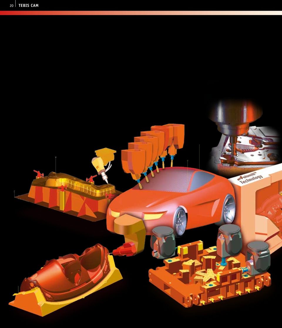
4 4 Tebis process chains CAD/CAM manufacturing solution that meets the highest standards Companies in manufacturing-intensive industries use Tebis software to organize their CAD/CAM process chains, thereby creating a robust and reliable platform. Tebis CAD/CAM and Viewer stations have become established as essential elements in high-efficiency manufacturing process chains, particularly in the automotive, aerospace and industrial manufacturing sectors. Tebis workstations can be smoothly integrated into design departments existing CAD infrastructure, and Tebis supplies the machines with safe NC programs required to manufacture the components. The CAD interfaces let you import CAD models from almost any CAD systems. All interfaces are designed to process components of any size. Depending on the format, the system copies over geometrical information and structural information such as assembly, layer, filter, feature and color data. The CAD analysis functions in the Tebis Base setup analyze imported data sets for manufacturing-relevant problem areas. The system helps you comfortably repair any shortcomings found. The CAD design modules in Tebis were designed for specialized manufacturing tasks. As a result, your manufacturing technology can be constructively integrated in an uncomplicated and timesaving way. That includes resources, such as dies and injection molds, as well as data control models, function models, prototypes and low-volume parts. High-quality Tebis surfaces technology can be used to create surfaces from FEM and STL meshes, optimize existing surfaces for quality and edit them for their technological objective, such as overbending for example. For more safety and higher-quality manufacturing results, use the Tebis CAD functions to generate run-off, extension and protection surfaces and structure components by milling and stop surfaces. Die manufacturing Getting to die release more quickly with Tebis CAD/CAM software: Fast and reliable processes, from surface design and NC machining of all shaping and structural parts of the die and through the try-out cycles. Mold manufacturing Mold manufacturing with optimized manufacturing processes. You stay in one system environment, from CAD design, 2.5D machining, hard tooling to electrode design and manufacture. NC programming of wire EDM machines also takes place in Tebis. Tebis Simulator systems support manufacturing planning and validation, and Tebis Viewer stations provide support for tool assembly.

5 Tebis process chains 5 Tebis CAM modules create safe and run time-optimized NC programs from users tested and saved strategies and input parameters. Tebis supports the manufacturing processes 2.5D drilling and milling, 3 to 5-axis roughing and finishing of surfaces, contours and tubes, 5-axis laser cutting, 5-axis trimming and 4-axis wire EDM. The integrated tool library, saved machining templates and realistic simulation options generate process-safe NC programs that are easy on your tools and require little programming work and minimal run times on the machines. You can use the configuration options in Tebis to standardize manufacturing processes tailored to suit the customer, and thus automate them. A variety of libraries are available to manage the milling and drilling tools, electrode holders and blanks, machining features for drilling and milling and machining templates for standards and repetition parts. There are also virtual machine models and approach and retract macros for milling. The shop floor products further tighten up and safeguard your manufacturing processes. For example, using the Tebis Viewer systems you can eliminate time-consuming 2D drawing for documentation and manufacturing purposes. Using Simulators with their virtual machine models will produce high savings potentials in NC programming and in machine manufacturing because the available target machines and their kinematics and workspace limitations can be taken into consideration right from the start. The CAQ modules then provide computer-supported quality control in Tebis format. That enables targeted insertion of measurement points onto CAD models, such as electrodes, that can then be verified on coordinate measurement machines. That determines the mismatch compensation values that must be used when the electrode is used in the subsequent EDM process. Modelling and prototyping Use Tebis CAD modules to quickly develop high-quality surface models from digitized manual models. Tebis supports all subsequent design and manufacturing tasks with CAD modules for surface design and 3 to 5-axis milling. Aerospace and industrial engineering Feature-based NC programming saves enormous amounts of time and increases safety. For complex components, the simulation options integrated into the CAM process provide additional safety and much reduced lead times.

6 6 Tebis product philosophy Tebis software helps optimize processes. Effortless handling of surfaces and meshes in each phase of the process chain The underlying Tebis hybrid technology lets you combine mesh surfaces (STL, FEM) and exact surfaces into any combination of element structures and further process them, for example when you have to digitize intermediate stages in the die manufacturing try-out process. Tebis makes it easy to generate exact surfaces from mesh surfaces, resulting in complete, high-quality surface models that other designers can further process. Feature technologies enhance design standardization and manufacturing automation Designers use features to assign technological definitions to certain geometry elements and areas such as M12 tapped hole and standard pockets. Such feature objects are either copied through an interface from a prior CAD system or automatically detected in Tebis with the aid of a geometry scanner and placed, with database support. This allows you to realize a higher level of standardization in design but also ensures significant advantages in manufacturing, as each feature includes all information needed to produce it. The feature-supported NC programming is thus automatic and takes into account all necessary tool changes, including full collision protection.

7 Tebis product philosophy 7 Tebis machine simulation: High process safety and minimal lead times Manufacturing planners and NC programmers use the Tebis Simulator to clamp their components on virtual machines. They use it to image complete machining processes long before the actual machining, and even for multiple NC machines. You can run virtual feasibility tests for your manufacturing department, provide support for job cost planning and increase process safety with visualization, testing and optimization of your manufacturing processes. The Tebis Simulator accesses a virtual machine library containing detailed views of all NC machines in your own manufacturing department as well as your customer s. In addition to geometric dimensions, the library also stores kinematic conditions such as axis limit switches and travel during tool changes and positioning movements. This lets manufacturing planners, NC programmers and machine operators run through the entire manufacturing process on virtual machines. If collisions and limit switch triggers are detected, the system lets you make appropriate changes to the clamping arrangement or tool and recalculate modified NC jobs. Tebis Viewer: Paperless communication for the very latest information Tebis process chains have eliminated the derivation of 2D drawings almost entirely for documentation and manufacturing purposes. This saves a substantial amount of the time it takes to design molds and dies. Even production planners no longer document calculated NC programs on paper, which also speeds things up a lot. At the heart of Tebis process chains are the Tebis Viewer systems, which transfer all CAD and NC information to every station along the production process chain. Everyone involved, from NC programmers and machine tool operators to installers, can view the very latest information they need right on Tebis Viewer stations. In the end, even job cost planners benefit from the powerful analysis functions available on the Tebis Viewers.

8 8 Tebis Automill Leverage knowledge with individual configuration options Tebis software was developed to allow processing of both unique special projects and repetitive standard jobs in a manufacturing compliant structured manner. If it turns out that certain CAD/CAM processes are repetitive, you can increase throughput time and process safety enormously if you save the methods you have tested in your CAD/CAM system and have them available as templates. Tebis will support you with individually configurable model templates, NC job lists and a variety of configuration databases. Model templates as start models For different component classes, you can use layers and filters to predefine structures and create entire NC job lists in advance according to a standardized process. You can also predefine which centrally saved configuration databases the actual Tebis modelfile should link to. Depending on the job and the customer, you can thus use different model templates to define the feature, NC set, tool and machine libraries to which the Tebis model file should be linked. Automill DESIGN Die or mold design PRODUCTION PL ANNING Data import Data processing Blank definition Select template Import data View data Correct features Add features Create auxiliary surfaces Import blank Check blank Edit blank Align blank to part geometry Templates Part classes Part structures Working plans Configuration databases Features Drill holes Standard pockets Freeform pockets Planar surfaces Outlines NC Sets Parametric machining specifications Tools Cutters Holders Tool assemblies

9 Tebis Automill 9 Configuration databases In Tebis, what are known as libraries are available for a variety of objects and processes that can provide enormous savings when used in methodical NC manufacturing: Feature library for putting drilling and pocket objects into CAD models Electrode holder and blank library for deriving electrodes for injection molding tools NC set library for generating NC programs fully automatically for repetitive machining sequences Tool library for realistic descriptions of tool assemblies and tool components Machine library for taking the machine and the clamping position into consideration for NC programming and machining Tool set library for managing tool change magazines NC job lists In each model file, Tebis creates an NC job list in which all the NC machining steps are saved with all the necessary tools and all the area selections and parameter inputs. Toolpaths calculated on this basis will always retain their NC job reference and can be recalculated immediately after any changes to the parameters. Another advantage: NC job lists can be copied to components of similar type. The machining structure already worked out is thus quickly and easily copied to a different component, enormously reducing programming time. SHOP FLOOR NC programming NC simulation Machine manufacturing Clamping position Select machine tool Select setup position Position clamping devices Analyze feasibility Define machining sequence Generate machining automatically Appoint machine tool Align setup position Adjust clamping devices Check feasibility Adjust machining process Optimize machining sequence Create NC programs and NC documentation Tool list NC program Machine tools Kinematics Heads Limit switches Machine macros Postprocessor formats Tool magazines Standard tools Job related tools

10 10 Tebis CAD

11 Tebis CAD 11 TEBIS CAD Tebis offers a number of different CAD upgrade options. Six different CAD modules can be added to the Tebis Base, already including wire frame model design: Surface Design Advanced Surface Design Digitized Data Processing Rapid Surface Creation (RSC) Electrode Design Feature Design These options let you configure your CAD/CAM workstations to meet the needs of the application at hand. You can also choose from a number of geometry interfaces to meet your particular requirements and thus be compatible with everyone involved in the manufacturing process. Special time-saving functions for tooling design Tebis CAD stations provide a wide range of specialized design functions for constructively incorporating manufacturing technologies, including fillets, component partitions and draft angles in casting as well as overbends, radius reductions and trim line developments in sheet-metal working. Tebis also has an automated solution for designing electrodes in mold manufacturing. If geometric or economic considerations make it impossible to use milling technology, EDM electrodes can be derived quickly and easily. CAD plus CAM technology ensures highest quality and flexibility in NC manufacturing Efficient production planning and scheduling is possible only if NC programmers also have powerful analysis and CAD functions. Production planners use Tebis stations to analyze imported data sets for problems and repair any problem areas quickly and precisely. Add-on, extension and protection surfaces are generated to enhance reliability and improve the quality of milling results, while the parts are structured according to cutting and stop surfaces. Tebis hybrid core supports surfaces, meshes and solids Tebis designers work both with digitized STL surfaces and FEM meshes and with polynomial surfaces created or imported via curves and interfaces. The Tebis hybrid technology enables both. Imported solids are kept together in a structured fashion as topological composites. In principle, in Tebis all the surfaces can be machined and optimized in a targeted way that allows them to be converted to solids immediately in the target system. Wire frame technology provides the highest surface quality with minimum work The wire frame technology integrated into the RSC module (Rapid Surface Creation) makes the handling as easy as possible while ensuring low-segmentation surfaces with constant tangents and minimum gaps between the individual surfaces. Use the wire frame to comfortably create surfaces on predefined meshes. It also provides targeted quality optimization of surface models. Tebis RSC turns digitized surfaces into high-quality surface models. The Electrode Design module is used to derive and manage electrodes from the part geometry. With the wire frame, you can administer your surface models with a graphically interactive user interface in Tebis. Extremely useful automatic functions are available for deriving dies and molds from the part geometry.

12 12 Tebis CAD Tebis Base: Generating and modifying wire frame models. Analysis, navigation and documentation. Every Tebis workstation comes with a comprehensive range of useful functions and commands no matter which modules are installed: Wire frame model design: Do all design tasks necessary to create wire frame models. Create limiting and guide curves as well as auxiliary elements such as planes and axis systems in preparation for milling. Use edit functions to move, rotate, trim and limit existing curves and surfaces. Analysis: Evaluate design quality, determine modified areas with the distance analysis function, look for undercut areas with the slope analyzer and check entire components for fillet surfaces and planar areas. Navigation: Use the structure tree to display component areas individually or in groups, create new layers and filters and modify their contents. The toolbar lets you control component animation and determine whether to display the CAD model with shading, with the lines hidden or as a wire frame model. Documentation: Use the documentation functions to send views and sections to the printer or plotter and write them to files. System settings: The Base module provides an extensive configuration mode, where you can set individual parameters in Tebis, such as the graphic display of geometry elements, the selection performance and automatic name assignments. The curve functions are used to create all kinds of wire frame constructions, such as milling area boundaries. Display individual component areas with the structure tree. Display large components in hidden line mode for greater clarity. Documentation functions for printing and plotting. Analyze design quality with the quality function. Analyze changes with the distance analysis function. Analyze fillets with the radius analyzer. Analyze undercut areas with the slope analyzer.

13 Tebis CAD 13 CAD interfaces: Exchanging data efficiently. As the CAD/CAM systems available on the market become increasingly specialized, powerful interfaces are now more important than ever before. The ability to exchange data smoothly has become a central consideration in deciding who gets a contract. Tebis provides a number of standard and direct interfaces that allow data to be exchanged efficiently in both directions. They allow the 1-on-1 transmission of both geometric and structural data, including assemblies, layers, sets, filters and color information. Data can thus be transmitted effortlessly and without losses via the Catia and Unigraphics native interfaces versus outputting the original data in a neutral format. All interfaces are designed to import and export components of any size. You have the option of optimizing the original data set with intelligent filters when you import it. The following Tebis interfaces are available: Catia V4 direct interface Catia V5 direct interface Unigraphics direct interface Pro/E direct interface VDAFS standard interface VDAIS standard interface DXF standard interface STL interface Tebis provides a number of standard and direct interfaces for the exchange of data in both directions. The CAD data of molds and dies of any complexity is analyzed and compressed as it is being imported. The system can handle data of any size. CAD models that have been imported via the Catia V4 direct interface retain their original colors and filter structures when displayed in Tebis. Tebis imports Catia V5 product/part structures 1:1.

14 14 Tebis CAD Surface design: Generating and modifying surface models. The Surface Design module provides a comprehensive package of functions for generating and editing surface geometries. They can be used for creating a wide range of entities, from standard 3D surfaces (such as spheres, cylinders, cones and shift or rotation surfaces) to high-quality blending, fill, offset and fillet surfaces. Combined with the wire frame model functions that come with the Tebis Base, this module lets you construct surfaces of any complexity that meet the strictest quality standards. Whether you want to transfer existing geometry templates from another CAD system, design from drawings or just give your creativity free rein, the Tebis Surface Design CAD module gives you all the functions you need. Fill surfaces fit tangentially with adjacent surfaces. Modern and intuitive commands make it easy to create models, molds and dies. You can generate 3D standard surfaces as well as shift and rotation surfaces at the press of a button and construct free surfaces from curves and intersections. Surfaces and faces can be grasped and extended interactively. Tebis gives you interactive functions to construct fill and blending surfaces as easily as fillet surfaces with constant and variable radii. Powerful topology functions let you create component-wide BREP structures that provide enormous time and quality advantages when editing solids and preparing for milling. Offset surfaces let you generate wall thicknesses for complex surface structures at the click of a button. Design fillet surfaces all over the component: either automatically or interactively, with continuous or variable radii. Frequently used to prepare and structure surface data for NC processing.

15 Tebis CAD 15 Advanced surface design: Specialized high-end functions. Depending on the design complexity of your work, you may need the additional capabilities of Advanced Surface Design. The module comes with powerful functions that help you easily perform highly specialized design tasks in both equipment design and milling preparation. For example, method planners use them to create global overbend areas and developments in sheet metal processing. Mold-makers construct complex parting surfaces and draft angles. Milling planners create run-off surfaces and close recesses with fill surfaces. The functions of the CAD add-on module are ideal for designing technological aspects into the component. They let you compensate for springback in sheet-metal parts and shape trim curves to prior stages of deformation. Fillet surfaces are automatically reduced up to a sharp edge to improve flow in the die. Typical application in sheet-metal working: overbending the part geometry to compensate for springback. Multiple-component surface extension functions let you quickly and easily create parting surfaces and draft angles for foundry and injection molding work. Free surfaces can be infinitely shaped and connected tangentially to adjacent areas. The Tebis wire frame and surface design functions help you perform complex design work completely, quickly and easily without having to switch CAD systems. Adding draft angles frequently requires a great deal of patience but not with Tebis. Tebis lets you close all holes and recesses at the press of a button an essential advantage in preparing for milling.

16 16 Tebis CAD DIGITIZED DATA PROCESSING: Digitizing surfaces and optimizing STL meshes. The Digitized Data Processing module gives you CAD tools for further processing optically or mechanically digitized surfaces. They close gaps, tighten and smooth surfaces, bend and trim them to curves and generate closed mesh models that you can scale as needed. This gives you a very powerful software for quickly transferring an existing physical object to the CAD world, modifying it there and preparing it for rapid surface design or NC programming. Tebis imports your original digitized data from a variety of sensor systems along with any precalculated STL files, turning them into high-quality CAD mesh surfaces that you can process further as you wish, using Tebis editor functions. Hybrid technology lets you combine digitized surface areas (yellow) with designed exact surfaces (orange). The Tebis hybrid technology permits any combinations of the mesh data with polynomial surfaces. You ll benefit from the greatest possible degree of flexibility: you design with meshes wherever these elements are useful. Wherever necessary, you can add exact surfaces via sections or using the RSC CAD module. To convey mesh models or hybrid models consisting of meshes and polynomial surfaces to the real world quickly and precisely, just use the Tebis CAM modules, which work on mesh and hybrid models as efficiently as they do on surface data. Convert existing CAD topologies to meshes at the press of a button, then output them via the STL interface. Use the Tebis CAM modules to process combination CAD models consisting of meshes and surfaces. Individual digitized areas of surfaces that were modified by hand are automatically adjusted to the component.

17 Tebis CA Tebis CAD 17 RAPID SURFACE CREATION (RSC): Easy generation of high-quality surfaces. The Rapid Surface Creation CAD module is used to quickly produce high-quality surface models from existing mesh data that you either prepare with the digitized data module or import via the STL interface. Design model makers can derive from digitized manual models CAD surface models that will meet the requirements of downstream design departments. Die makers use RSC to reintegrate try-out changes into the CAD cycle. Tebis RSC creates and updates surface elements within the RSC topologies fully automatically. Users merely have to predefine the structures for the surfaces. They do this using the wire frame they create and optimize with various aids. After making manual changes to a part that was produced with CAD/CAM methods, the existing surface structures can be transferred to the latest mesh model from the primary CAD design. Particularly advantageous: Tebis supports trimmed surfaces, which has positive effects both on the work required to generate the surfaces and on the surface quality. Users use the wire frame and permissible offset tolerances to control the degree and segmentation of surfaces produced and their tangential conditions. Analysis functions reveal problems in the surface run, which can be quickly optimized simply by modifying the wire frame. The edges of the wire grid are created in part automatically by evaluating the curvatures and in part using the graphic interface with the aid of the drawing functions. Because Tebis supports trimmed surfaces, downstream designers are happy to accept its results. After manual changes, Tebis RSC projects the original surface structures onto the digitized surface and generates an updated surface model.

18 18 Tebis CAD ELECTRODE DESIGN: Database-supported design with simulation on the virtual model. The Electrode Design CAD module gives designers and NC programmers in mold manufacturing a software tool for deriving the necessary burn areas for EDM electrodes and turning them into complete electrodes with access to blank and holder libraries without requiring any prior specialized knowledge of design or CAD techniques. Analysis functions show the areas requiring further erosion after milling. Libraries for electrode blanks and holders are available for electrode design. EDM simulation tools let you check critical movements and detect possible collisions with the electrode base and holder. Functions for managing parts lists and documentation enable users to maintain clarity even when working with many or complex electrodes, and to make sure that electrodes are complete. The residual stock function identifies areas that need to be eroded. A color code shows the stock thickness after milling. A Tebis CAD/CAM workstation offers enormous advantages for the overall process in electrode design. Every step is more efficient and reliable, from design and milling to EDM itself. The electrode will automatically be designed ready for production. Blanks and holders can be taken from database libraries. The system stores all specifications for automated design, such as usage location, dimensions and holders, in the design assistant.

19 Tebis CAD 19 FEATURE design: Database-assisted handling of drilled and pocket objects of any complexity. Use the CAD module for Feature Design to design standardized geometry objects into tools and molds. For that, Tebis provides its own feature library in which these parametric manufacturing objects are administered. Every version of each feature is described precisely, both geometrically and technologically. Helpful functions let you place features in the component and adapt them to the local conditions. When importing component geometries, Tebis automatically scans and evaluates areas that can be described by feature objects. But the greatest benefit of Tebis features is from the way they automatically transport all values and information all the way through to the NC machine. Feature design with Tebis accelerates and simplifies CAD work. You can copy manufacturing information from prior CAD systems in the form of features. That clearly documents in the CAD model what has to be manufactured. The features contain all geometrical and technological parameters for the manufacturing task, such as: M10 threaded blind hole, 25 mm deep, or 25 x 8H7 slot, 5 mm deep. This data will no longer have to be detailed in drawings for manufacture. Tebis also quickly and reliably detects the feature-relevant geometries in any imported data and places features there. This also functions with 2D drawing data. The feature technology is useful not only to designers, but in manufacturing as well. In subsequent NC programming work, NC programs can be automatically calculated for feature objects without any further intervention on the part of the programmer. The nozzle side of an injection molding die with over 170 features, from a simple tap to a multi-stepped cooling hole with screw connection. The feature library lets you define all necessary hole geometries and production information and manage them in a structured system. The feature scanner has identified a group of water lines and suggests the best choice of elements from the library. Use the feature editor to change built-in features later on.

20 20 Tebis CAM
21 Tebis CAM 21 TEBIS CAM Tebis offers multiple upgrade options for CAD/CAM and CAM workstations. You can add up to nine CAM modules to the Tebis Base and CAD modules, thus configuring workstations with a variety of performance ranges: 2.5D Drilling and Milling 3+2 Axis Roughing 3+2 Axis Finishing 3+2 Axis Residual Stock Removal 3+2 Axis Tube Milling 5-Axis Simultaneous Milling 5-Axis Laser Cutting 5-Axis Trimming 4-Axis Wire EDM Tebis Automill technology: Automatic NC programming combined with interactive intervention options for NC programmers Tebis NC programmers always have the option of accessing previously prepared, centrally stored machining sequences (NC sets), of copying NC machining steps from a related component (NC job list) or of programming individually, using individual NC functions. Technology specialists program recurring machining sequences in detail in NC sets, including all tools and cutting parameters, thus minimizing NC programming work. The NC job library saves all selections made and parameter data entered during the NC programming letting you simply and easily optimize calculated toolpaths for the tool, strategy and machining area. Another advantage is that all the NC jobs defined to manufacture a component can be copied to similar components, saving you a lot of programming work. The Tebis interactive step control continuously calculates the intermediate results and presents them to the user, who either accepts them or overrides the system, for example to set the machining sequence of different cutting zones. Calculating NC programs directly on the CAD surfaces, including mesh and mixed data The surfaces produced with Tebis CAM modules meet high quality standards because Tebis always calculates the toolpaths on mathematically precise CAD surfaces. Tebis uses simplified mesh models only when no exact surfaces are available in which case the system calculates NC programs on the basis of mesh and hybrid models as well. Reliable, efficient machining with integrated tool management Each NC program generated in Tebis is calculated on the basis of the underlying tool geometry. In addition to cutting dimensions, the internal tool library in Tebis also includes all holder components. That lets you reliably avoid holder collisions and define optimum tool lengths and approaches. For each cutter, Tebis manages not only the geometric data, but also the cutter material and materialspecific parameters (feed rates, speeds). High-quality simulation technologies enhance process reliability and minimize lead times Tebis simulation tools can predict real production sequences as early as the NC program calculation stage. For example, the selected cutting tool can work the component plane by plane on the machine. Virtual production tracking shows the blank as it gradually takes on the shape of the target geometry, always knowing where and how much stock still remains on the part. The advantages for you are less idle travel and dramatically shorter run times. Not only does this prolong tool life, it also increases process reliability.
22 22 Tebis CAM 2.5D drilling and milling: Fully automatic, knowledge-based NC machining. Typical application areas for this Tebis CAM module in die manufacturing include planar surfaces, seating surfaces, and fit and tapped holes for attaching trim steels to sheet metal dies. Mold manufacturers use the module for machining all kinds of pocket and planar surfaces as well as holes, such as step or deep-drilled holes for cooling and heating systems. But industrial and aerospace engineering are also typical application fields. Use the drilling functions to program NC programs for bore holes, threads and fits. You can use the milling functions to create individual NC programs for pockets and planar surfaces and for vertical contours and their residual stock machining. With the feature technology, the functions will copy over all the geometry information with a single click of the mouse. 5-sided complete machining: planar surfaces and pockets are machined from multiple sides on a forging die. Collision protection and optimized retracts: the component geometry is always accounted into the calculation. Effective and safe automation NC set technology provides special advantages for 2.5D NC programming. The system accesses old machining sequences (NC sets) that were defined in the past by milling specialists and have been saved to a central location. The NC sets bundle individual functions for standardized machining steps such as multi-stepped holes, taps and pockets, including all necessary tools and the optimum cutting parameters. If the CAD model contains features (parametric manufacturing objects), NC programming can take place completely automatically because each feature will find the NC set defined for its manufacture. This will result in enormous reductions in NC programming work while increasing safety. The 2.5D programming from Tebis is also best suited for complex deep hole drilling in mold manufacturing. NC set technology automatically calculates NC programs for all types of holes and pockets.
23 Tebis CAM axis roughing: Shorter run times and less wear on tools. Tebis roughing involves removing stock from a user-defined blank plane by plane from top to bottom, thereby approaching the desired target geometry in a terraced representation. The virtual tracking function lets you see, as early as the program calculation stage, exactly what the part will look like on the real machine. As early as the NC program calculation stage, Tebis generates the same intermediate geometries, plane by plane, that you get when machining with the selected milling tool in the real world. By doing this, the system continuously updates the original blank geometry. As a result, Tebis always knows how much material remains and where it is located, thus dramatically reducing idle travel and therefore also run times. Intelligent algorithms also make sure that contour characteristics are gradual and gentle on the tool, enabling you to mill at very high feed rates. Depending on the tool contact, Tebis outputs different feed rates, reducing the feed rate when making a full cut for example. As a further advantage, continuous collision protection is run on current machining states and not only the target geometry to be achieved. Material thickness analysis for efficient remachining The intermediate geometries calculated by Tebis also provide information about the thickness of the material remaining on the target geometry. This function quickly, reliably and precisely finds the sites in the component that still contain too much material. And that makes possible extremly efficient strategies such as machining with large milling tools and high cutting capacity, coupled with remachining programs that are applied only to the areas where material still remains. The calculated intermediate geometry (left) is used as a new blank geometry for remachining. The material thickness analysis localizes the areas (red) where too much stock still remains. To streamline the roughing programs, you can digitize the blank casting and provide it as the blank geometry. A different tool orientation is ideal for machining particularly steep and excessively undercut areas. High-speed roughing, thanks to rounded, smooth and thus HSC-capable NC paths. Spacing the planes closer together breaks up the terrace representation. The material thickness analysis creates boundary curves for selective remachining in areas where too much stock remains.
24 24 Tebis CAM 3+2 axis finishing: Optimum surface quality for components of any complexity. The 3+2 Axis Finishing CAM module is ideal for semi-finishing, finishing and HSC milling of 3D surfaces as well as contouring and corner picking. Tebis supports all cutter types, from scriber, ball-end and torus cutters to end mills. Multiple milling strategies are available for each machining function. Tebis calculates the toolpaths either automatically or with interactive intervention. The system automatically determines the cutting zone limits and divides the component according to topological criteria. The result is a collision-checked NC program that meets the strictest quality standards. Special HSC parameters are available for calculating NC programs that are used in high-speed milling applications. The right machining strategy for the very best results Tebis offers all the milling strategies that die, mold and pattern manufacturers need. Thus, NC programmers can choose the right strategy, axis-parallel, curve-parallel, contour-parallel, z-profiling and isoparametric, for surface finishing and HSC milling, depending on the component geometry and quality requirements. The automatic geometry analysis routines provide help in determining area and slope angle curves, taking the selected tool into account. Unlimited component size and complexity This module lets you easily produce core and cavity molds, taking material thicknesses and stock allowances into account. The components can be of any size and complexity. All NC programs including infeed motions are checked for collisions as early as the calculation stage. To improve surface quality, z-profiled toolpaths occur in steep areas of the component, while axis or contour-parallel NC programs are automatically calculated in shallow zones. Tebis automatically calculates cutting zone limits for the selected tool. With the contour-parallel strategy, you can also use the localized zone limit as a guide element.
25 Tebis CAM axis residual stock removal: Field-tested strategies to reduce run times. The combination of large milling tools and high cutting capacity, followed by small cutters for remachining, is the most effective way to mill surfaces. The Tebis 3+2 Axis Residual Stock Removal module locates the areas to be remachined and automatically calculates the necessary toolpaths. To use this strategy the system must reliably detect the component areas that a larger milling tool was unable to reach. This Tebis module is the ideal tool for this purpose. It helps NC programmers remachine specific fillets and other concave recesses. When determining the residual stock zones, Tebis takes the cutting-edge geometries as well as the preceding and following tools into account. The system accepts end mills as well as torus and ball-end cutters. The right strategy for perfect surface finish You can use different strategies to machine residual-stock zones, such as milling along the fillet in shallow areas and bump-cutting in steep regions. Tebis makes a distinction between flat and steep areas according to on the limit angle entered. Depending on the component steepness, an axis-parallel, contour-parallel or z-profiling strategy can be selected for milling corners and grooves. For contour-parallel machining, the system automatically uses the previously determined area limit as the boundary contour. Residual stock removal program in all fillets of a complex inner door panel die. Machining the fillet by z-contouring. Contour-parallel fillet machining with an indexed tool.
26 26 Tebis CAM 3+2 axis tube milling: 3-axis machining of bent intake and exhaust ducts. Tebis V3.3 was the first version to provide the Tube Milling CAM module for milling bent intake and discharge ducts. The key feature of this module is that it generates 3-axis roughing and finishing paths for key and ball-end cutters. The special geometry of these cutters enables complete processing of curved tubes. Tubes that are particularly long with sharp bends are divided into two sides for machining purposes. The tubes can be machined either horizontally or vertically using climb cuts, conventional cuts and lacing techniques. Horizontal machining produces a helical path with the down-cutting and up-cutting strategies. Horizontal machining produces a helical path with the down-cutting and up-cutting strategies. The flow-cut strategy works best for roughing.
27 Tebis CAM 27 5-axis simultaneous milling: The fastest way to achieve smooth surfaces. The Tebis 5-Axis Simultaneous Milling module lets you machine certain surface and curve steps faster and more accurately than with the 3-axis technology. 5-axis NC programs are no more difficult to calculate than those in the 3+2-axis modules, since they implement the same user structures. In milling surfaces, this module is a good choice for both convex components and cavities. The collision check takes into account the holder components defined in the tool library. Advanced strategies for three-dimensional trimming, engraving and surface milling The curve machining functions calculate 5-axis programs for etching and engraving as well as cleaning the boundary areas of 3-dimensional sculptured surfaces. When face-milling cavities, you can specify limit angles to avoid holder collisions. Tebis provides a number of different options for machining curves, for example cleaning boundary areas with the cutter always positioned vertically relative to the surface. Functions and strategies for roll and face-milling are available for surfaces. You can define stop and boundary surfaces to protect adjacent surface areas against contact with the tool. Toric tools and the use of approach and departure macros help you achieve ideal surface results. Convex sculptured surfaces can also be roll-milled. To define surface programs, you can select two curves between which both the path course and distance will be interpolated. NC calculations also take head geometry and machine kinematics into account The system takes into account the tool being used, the head geometry and machine kinematics as early as the NC program calculation stage. Immediately afterwards, every calculated 5-axis NC program can be simulated in shaded real-time mode and analyzed for holder collisions.
28 28 Tebis CAM 5-axis laser cutting: For try-outs, prototypes and series. This CAM module is used to generate 2 to 5-axis NC programs offline for laser cutting applications. Using this software, you can trim auto body sheet metal parts for prototypes and series. Die makers use Tebis laser cutting stations to test drawing operations in the try-out phase to find out how to compensate for the springback behavior of the trimmed sheet metal parts. 5-Axis Laser Cutting provides both cutting functions for machining free curves and for generating regular geometric inner contours such as circles and slots. The system automatically monitors the machine s kinematic properties such as tilting limits or preferred starting position during toolpath calculations. Users can jump in at any time however and manually define the head position and orientation. The system supports users with its comprehensive analysis functions for the rotation angle course, normal deviations and collisions. The Tebis NC jobs administer all change statuses and define mirrored, rotated or moved machining steps. Semi and fully automatic collision checking When the NC programs are calculated, the part and trim areas are automatically checked for collisions, taking the entire laser head into account. These collision checks can be extended to clamping elements. Tebis automatically determines where there is a risk of collisions with the component or another element and lets the user remedy the situation graphically and interactively. Modifications added to the NC program at the machine can be read back into the NC jobs. That lets changes be edited in Tebis. After you define a component, the system will automatically create the supports and base plate for a clamping arrangement that fits it exactly. You can use the interactive graphic user interface to change the approach of the laser head. This together with the extensive online analyses creates collisionfree and consistent paths. You can also check the NC programs later on for collisions with the cavity geometry and possible obstacles, and change them if necessary. Tebis automatically detects radii and provides NC programs with G02 and G03 flags.
29 Tebis CAM 29 5-axis trimming: For trimming components made of composite materials. With the Tebis CAM module for 5-Axis Trimming, you can create 3- to 5-axis NC programs for trimming in offline mode. In doing so, you will move the teach-in process for your trimming steps from the machine to the virtual world of the CAD/CAM seat thus reducing costs and downtime. The softwares application areas range from trimming vacuumformed plastic parts to machining carbon and glass fiber-reinforced plastic parts and the use of robots for serial production. Tebis supports the machines of all the popular manufacturers. Graphically interactive follow-up treatment of NC paths Users can comfortably simulate and analyze calculated contours. The system automatically recognizes and graphically highlights areas with major rotational movements of the machine head or high lateral inclination just as it recognizes and highlights areas at risk for collisions. Powerful, graphically interactive functions are available for subsequent processing of the identified path areas. Switching to different machines Thanks to Tebis technology, the machining of components is no longer bound to certain specific machines. With the reverse processors, you can also machine jobs for which you have no CAD data on different machines. When switching machines, use the reverse processor to import already generated NC programs and export them as NC programs for a different machine type. The orientation of the machine head can be easily changed with the mouse. Together with the automatic analysis functions, this lets you define collision-free head orientations. Machine head positions (yellow) are transferred into the NC program and imported into Tebis. The original approach vectors are displayed in red. You can also re-import moved positions of shape elements that were defined as a cycle in the NC program.
30 30 Tebis CAM 4-axis WIRE EDM: Sharp trimming of tool inserts and electrodes. The CAM software for programming 2-axis and 4-axis wire EDM machines is a powerful technology package that specializes in the manufacturing requirements found in die and mold manufacturing. Because the application is integrated into Tebis, wire EDM programs can be calculated and output directly without extra interface runs. The interactive user interface lets even less experienced users quickly and effectively create optimum NC programs. The option of being able to access at any time a complete CAD system with fundamental design and analysis options has proven to be a considerable advantage, throughout the entire programming process. Fully integrated machine technology Tebis software will manage all the technology parameters for nearly every machine currently on the market. It supports 20 NC controls with over 100 generator and software versions. If the machining process has to be switched to another machine, the system will generate the NC program for the new machine complete with all the technological parameters. In such cases, a fully automated conversion run will compute the new NC program and list any inconsistencies that may arise. Users can then eliminate them very easily using an interactive user guide. Tebis has completely eliminated the often time-consuming task of assigning upper contours to lower contours in conical cuts and complex geometries and the sometimes associated counterfeiting of the actual design geometry. The reason: The NC paths are calculated directly on the underlying surfaces and solids, using the existing surface information. Results in minutes thanks to intelligent template technology A comfortable job browser helps users define their process sequences. You can select prepared standard sequences or access individual strategies for any conceivable machining task. In most cases, you will only have to assign a few parameters, such as bore hole and contour, and the Tebis software will take care of the rest by using pre-existing templates. The system also identifies 3D contours directly and without errors, using all their surface information. Mold and die manufacturers already using Tebis to run their milling and who also count on Tebis when designing and manufacturing electrodes can now use the same CAD/CAM system to calculate and export their wire EDM programs.
SprutCAM is a CAM system for NC program generation for machining using multi-axis milling, turning, turn/mill, Wire EDM numerically controlled
 SprutCAM is a CAM system for NC program generation for machining using multi-axis milling, turning, turn/mill, Wire EDM numerically controlled machines and machining centers. The system enables the creation
Optimized NC programming for machinery and heavy equipment. Summary NX CAM software redefines manufacturing productivity with a full range of NC
 Siemens PLM Software NX CAM for machinery Optimized NC programming for machinery and heavy equipment Benefits Effectively program any type of machinery part Program faster Reduce air cutting Automate programming
CimatronE Version 8.0 A Product Review Summary
 CimatronE Version 8.0 A Product Review Summary August 2006 A CIMdata Review CimatronE Version 8.0 A Product Review Summary August 2006 Prepared by CIMdata Copyright 2006 by Cimatron Ltd. and CIMdata,
CAD-CAM 3D PROGRAMMING SOFTWARE FOR LATHE, MILLING AND EDM CNC MACHINES
 italtec UNI EN ISO 9001 AUTOCAM-2000 CAD-CAM 3D PROGRAMMING SOFTWARE FOR LATHE, MILLING AND EDM CNC MACHINES As manufacturing technology continues to move forward exponentially, the dependence on CAD/CAM
NX for Tooling and Fixture Design Transforming today s processes for designing and manufacturing injection molds, dies and fixtures
 for Tooling and Fixture Design Transforming today s processes for designing and manufacturing injection molds, dies and fixtures fact sheet Siemens PLM Software www.siemens.com/nx Summary The software
V10.2 / V11.2 Die CAM 3D
 CAA V5 based V10.2 / V11.2 Die CAM 3D October, 2011 UNIADEX, Ltd. Die CAM 3D Die CAM 3D/CAM 3D automates and optimizes machining for die product shape. -Various machining operation with with users users
Optical Digitizing by ATOS for Press Parts and Tools
 Optical Digitizing by ATOS for Press Parts and Tools Konstantin Galanulis, Carsten Reich, Jan Thesing, Detlef Winter GOM Gesellschaft für Optische Messtechnik mbh, Mittelweg 7, 38106 Braunschweig, Germany
Automotive Applications of 3D Laser Scanning Introduction
 Automotive Applications of 3D Laser Scanning Kyle Johnston, Ph.D., Metron Systems, Inc. 34935 SE Douglas Street, Suite 110, Snoqualmie, WA 98065 425-396-5577, www.metronsys.com 2002 Metron Systems, Inc
NX CAD/CAM 3-Axis Milling Foundation
 CAD/CAM 3-Axis Milling Foundation NX CAM benefits Automated hole making capability speeds common processes Boundary-based cutting provides flexibility to cut on minimal geometry Solids-based cutting cuts
How To Make A Global Cad/Cam Solution For A Large Company
 YOUR GLOBAL CAD/CAM PRODUCTION SOLUTION THE INTEGRATED CAD/CAM/ERP SOLUTION A GLOBAL CAD/CAM SOLUTION Missler Software offers a comprehensive, high-performance software application for all types of machining
Surface Machining. NATIONAL INSTITUTE FOR AVIATION RESEARCH Wichita State University. Revision 5.13 Copyright 2004. All rights reserved.
 Surface Machining NATIONAL INSTITUTE FOR AVIATION RESEARCH Wichita State University Revision 5.13 Copyright 2004. All rights reserved. www.cadcamlab.org None of this material may be reproduced, used or
CATIA V5R21 - FACT SHEET
 CATIA V5R21 - FACT SHEET Introduction What s New at a Glance Overview Detailed Description INTRODUCTION CATIA V5 is the leading solution for product success. It addresses all manufacturing organizations;
CATIA Drafting TABLE OF CONTENTS
 TABLE OF CONTENTS Introduction...1 Drafting...2 Drawing Screen...3 Pull-down Menus...4 File...4 Edit...5 View...6 Insert...7 Tools...8 Drafting Workbench...9 Views and Sheets...9 Dimensions and Annotations...10
FAGOR CNC 8055 ia-mc Control
 FAGOR CNC 8055 ia-mc Control The Fagor 8055 i/a-mc CNC control combines value & reliability with a featured packed modular control. This control was built for the shop environment with a rugged keyboard
CHAPTER 1. Introduction to CAD/CAM/CAE Systems
 CHAPTER 1 1.1 OVERVIEW Introduction to CAD/CAM/CAE Systems Today s industries cannot survive worldwide competition unless they introduce new products with better quality (quality, Q), at lower cost (cost,
Introduction to CATIA V5
 Introduction to CATIA V5 Release 16 (A Hands-On Tutorial Approach) Kirstie Plantenberg University of Detroit Mercy SDC PUBLICATIONS Schroff Development Corporation www.schroff.com www.schroff-europe.com
CAD / CAM Dr. P. V. Madhusuthan Rao Department of Mechanical Engineering Indian Institute of Technology, Delhi Lecture No. # 12 Reverse Engineering
 CAD / CAM Dr. P. V. Madhusuthan Rao Department of Mechanical Engineering Indian Institute of Technology, Delhi Lecture No. # 12 Reverse Engineering So what we will do in today s lecture is basically take
CATIA Functional Tolerancing & Annotation TABLE OF CONTENTS
 TABLE OF CONTENTS Introduction...1 Functional Tolerancing and Annotation...2 Pull-down Menus...3 Insert...3 Functional Tolerancing and Annotation Workbench...4 Bottom Toolbar Changes...5 3D Grid Toolbar...5
High productivity part manufacturing
 www.siemens.com/plm/nx/cam High productivity part manufacturing NX CAM a complete solution for making better parts faster www.siemens.com/plm The NX CAM advantage How does NX software help you make better
NX CAM TURBOMACHINERY MILLING PRODUCT REVIEW
 Dr. Charles Clarke PRODUCT REVIEW Market drivers...3 Existing specialist applications...3 A new generation of software that provides flexibility...4 Specialized operations for blisks and impellers...4
Automation of CNC Program Generation
 Automation of CNC Program Generation In a typical product manufacturing industry, there is a long lead time involved starting from the manufacturing plant layout, machine setup, product machining in CNC
2010 CATIA V5 CAM EĞĐTĐMLERĐ ĐÇERĐĞĐ
 CATIA V5 CAM EĞĐTĐMLERĐ ĐÇERĐĞĐ CATIA V5 CAM GĐRĐŞ EĞĐTĐMĐ (1 Gün) 1) Manufacturing Workbench Presentation Workbench Introduction Process Presentation Manufacturing Terminology Manufacturing Workbench
The PTC Creo Suite of NC and Tooling Solutions
 The PTC Creo Suite What you need to capitalize on global manufacturing excellence of NC and Tooling Solutions To gain a competitive edge in product development, companies are increasingly leveraging globally
accord 20 fx CNC machining centre
 accord 20 fx CNC machining centre accord 20 fx CNC machining centre New-generation modular machining centre designed for machining operations involving heavy duty stock removal with high precision and
How To Program A Laser Cutting Robot
 Robotics ABB Robotics Laser Cutting Software High precision laser cutting made easy - Greater manufacturing flexibility at lower capital investment Robotic laser cutting Overview Allows for the increased
Computer Aided Systems
 5 Computer Aided Systems Ivan Kuric Prof. Ivan Kuric, University of Zilina, Faculty of Mechanical Engineering, Department of Machining and Automation, Slovak republic, ivan.kuric@fstroj.utc.sk 1.1 Introduction
The NX CAM-SINUMERIK advantage
 The NX CAM-SINUMERIK advantage White Paper Optimizing the connection between CAM software and your machine tool controllers To get the best performance out of today s advanced machine tools, your company
Application Example: Reverse Engineering
 Application Example: Reverse Engineering Use of optical measuring technology in the ceramics industry Measuring system: ATOS Keywords: Reverse Engineering, Tool and Moldmaking, Quality Assurance, Ceramic
T-FLEX Parametric CAD is a full-function software system providing mechanical design professionals with the tools they need for today's complex
 T-FLEX Parametric CAD is a full-function software system providing mechanical design professionals with the tools they need for today's complex design challenges. It unites powerful parametric 3D modeling
Alphacam Art combines Vectric s Aspire artistic design software with the market leading Alphacam manufacturing software.
 Alphacam Art Alphacam Art - CNC Routing For Artists & Ideal Jewellery Cad Cam Software Alphacam Art combines Vectric s Aspire artistic design software with the market leading Alphacam manufacturing software.
How SolidWorks Speeds Consumer Product Design
 white paper How SolidWorks Speeds Consumer Product Design inspiration SUMMARY SolidWorks Premium bridges the gap between industrial design and engineering by providing powerful surfacing capabilities,
Electron S.R.L. B55 CNC TRAINING MACHINES
 Electron S.R.L. Design Production & Trading of Educational Equipment B55 CNC TRAINING MACHINES Specifications may change without notice Page 1 of 12 File B55 MODULAR TRAINING SYSTEM FOR THE STUDY OF CNC
CAD/CAM DESIGN TOOLS. Software supplied with all new and upgraded Boxford Lathes, Mills and Routers
 CAD/CAM DESIGN TOOLS Software supplied with all new and upgraded Boxford Lathes, Mills and Routers The Boxford CAD/CAM Design Tools software is a unique suite of integrated CAD and CAM tools designed specifically
Shop-Talk Cad/Cam The language between man and machine!
 Shop-Talk Cad/Cam The language between man and machine! The job shop progamming solution Its so simple even a CaveMan can use it! CNC Solutions, Inc. 13955 Murphy Road #122 Stafford, TX 77477 TEL: 832-407-4455
GIBBSCAM PRODUCTION SYSTEMS: MILLING, TURNING, AND MILL-TURN
 GIBBSCAM PRODUCTION SYSTEMS: MILLING, TURNING, AND MILL-TURN GibbsCAM simplifies the complex, with the power to meet the challenges of the most demanding shop. GibbsCAM Production Milling and Production
5-Axis Test-Piece Influence of Machining Position
 5-Axis Test-Piece Influence of Machining Position Michael Gebhardt, Wolfgang Knapp, Konrad Wegener Institute of Machine Tools and Manufacturing (IWF), Swiss Federal Institute of Technology (ETH), Zurich,
Tube Control Measurement, Sorting Modular System for Glass Tube
 Tube Control Measurement, Sorting Modular System for Glass Tube Tube Control is a modular designed system of settled instruments and modules. It comprises measuring instruments for the tube dimensions,
TABLE OF CONTENTS. INTRODUCTION... 5 Advance Concrete... 5 Where to find information?... 6 INSTALLATION... 7 STARTING ADVANCE CONCRETE...
 Starting Guide TABLE OF CONTENTS INTRODUCTION... 5 Advance Concrete... 5 Where to find information?... 6 INSTALLATION... 7 STARTING ADVANCE CONCRETE... 7 ADVANCE CONCRETE USER INTERFACE... 7 Other important
Solid Edge structural frames and weldments
 Solid Edge structural frames and weldments White Paper Intelligent, process-specific applications that speed time to manufacturing. White Paper Solid Edge structural frames and weldments 2 Contents Solid
CATIA Wireframe & Surfaces TABLE OF CONTENTS
 TABLE OF CONTENTS Introduction... 1 Wireframe & Surfaces... 2 Pull Down Menus... 3 Edit... 3 Insert... 4 Tools... 6 Generative Shape Design Workbench... 7 Bottom Toolbar... 9 Tools... 9 Analysis... 10
Precision Cutting. Confidence at the Router. Intelligent Machining. Powerful Part Modeling. Dependable Toolpath Verification
 Precision Cutting Intelligent Machining Confidence at the Consumer Furniture Fabrication Sculpture Cabinetry Powerful Part Modeling As the world s most widely-used CAM software,* Mastercam is dedicated
Presentation on CNC MACHINES. By: Hafiz Muhammad Rizwan
 Presentation on CNC MACHINES By: Hafiz Muhammad Rizwan WELCOME CNC Machines What is a CNC Machine? CNC : Computer Numerical Control Conventionally, an operator decides and adjusts various machines parameters
1) Cut-in Place Thermoforming Process
 Cut-in Place Thermoforming Process") Standard Thermoforming Equipment Overview There are three standard configurations for thermoforming equipment: 1. Heat and Cut-in-Place Forming 2. In-Line Forming with Steel Rule or Forged Steel Trim wand
Standard Thermoforming Equipment Overview There are three standard configurations for thermoforming equipment: 1. Heat and Cut-in-Place Forming 2. In-Line Forming with Steel Rule or Forged Steel Trim wand
THE INTEGRATED CAD/CAM SOLUTION FOR THE WOOD INDUSTRY THE INTEGRATED CAD/CAM/ERP SOLUTION
 THE INTEGRATED CAD/CAM SOLUTION FOR THE WOOD INDUSTRY THE INTEGRATED CAD/CAM/ERP SOLUTION ONE CAD/CAM SOLUTION AND ONE PROFESSION: WOOD TopSolid Wood is both a very powerful CAD/CAM solution, and a dedicated
Sheet Metal Shearing & Bending
 Training Objective After watching the program and reviewing this printed material, the viewer will gain a knowledge and understanding of the principles and machine methods of shearing and bending sheetmetal
MET 306 Activity 6. Using Pro/MFG Milling Operations Creo 2.0. Machining a Mast Step
 Using Pro/MFG Milling Operations Creo 2.0 Machining a Mast Step If the Trim option is grayed out when trimming the mill volume, Save (making sure the.asm file is going to the correct subdirectory), Exit
Structural design, manufacturing and communication for packaging and displays
 Structural design, manufacturing and communication for packaging and displays ArtiosCAD Find out why packaging professionals all over the world choose ArtiosCAD. ArtiosCAD is the world s leading structural
Design & Drafting Services
 Design & Drafting Services 1. Mechanical CAD Services 1. Mechanical CAD Services Mechanical Design Services: Custom machine design Packaging machine design Mechanism design Machine tool design Material
NX Advanced 5-Axis Machining
 Siemens PLM Software NX Advanced 5-Axis Machining Benefits Automated hole making capability speeds common processes Boundary-based cutting provides flexibility to cut on minimal geometry Solids-based cutting
Technical What s New. Autodesk Alias Product Line
 Autodesk Alias Product Line Purpose-built for industrial designers and creative professionals, digital modelers/sculptors, and automotive/transportation designers, the Autodesk Alias 2010 product line
High speed machining and conventional die and mould machining
 High speed machining and conventional die and mould machining Reprint from HSM - High Speed Machining There are a lot of questions about HSM today and many different, more or less complicated, definitions
An introduction to 3D draughting & solid modelling using AutoCAD
 An introduction to 3D draughting & solid modelling using AutoCAD Faculty of Technology University of Plymouth Drake Circus Plymouth PL4 8AA These notes are to be used in conjunction with the AutoCAD software
Weld Design. CATIA V5 Training Foils. Weld Design. Copyright DASSAULT SYSTEMES 1. Instructor Notes:
 CATIA V5 Training Foils Weld Design Version 5 Release 19 January 2009 EDU_CAT_EN_WD1_FI_V5R19 1 About this course Objectives of the course Upon completion of this course you will be able to: - Weld parts,
G10 Data Setting Command
 G10 Data Setting Command Though it s barely mentioned in most basic CNC courses, the G10 command is an extremely important basic CNC feature It allows you to input data from within CNC programs This data
AutoCAD 3D. MicroStation. Courseware Issued (Optional) AutoCAD (30 Days Trial Version) Reference Guide Project Workbook
 AutoCAD (30 Days Trial Version) Reference Guide Project Workbook") 2D CAD Introduction Isometric drawings File management Perspective drawings Orthographic drawings Annotations and Dimensions View management Team work Display management Layout management Layer management
2D CAD Introduction Isometric drawings File management Perspective drawings Orthographic drawings Annotations and Dimensions View management Team work Display management Layout management Layer management
SpaceClaim Introduction Training Session. A SpaceClaim Support Document
 SpaceClaim Introduction Training Session A SpaceClaim Support Document In this class we will walk through the basic tools used to create and modify models in SpaceClaim. Introduction We will focus on:
CATIA Electrical Harness Design TABLE OF CONTENTS
 TABLE OF CONTENTS Introduction...1 Electrical Harness Design...2 Electrical Harness Assembly Workbench...4 Bottom Toolbar...5 Measure...5 Electrical Harness Design...7 Defining Geometric Bundles...7 Installing
Seamlessly integrated for continuous processing. cad integration
 Seamlessly integrated for continuous processing cad integration hypermill in Autodesk Inventor The CAD integration of hypermill in Autodesk Inventor is a reliable solution that allows you to implement
ME 521 Computer Aided Design. 1. Introduction to CAD
 Computer Aided Design Yrd.Doç. e mail: azsenalp@gyte.edu.tr Makine Mühendisliği Bölümü Gebze Yüksek Teknoloji Enstitüsü Basic Definitions CAD: Computer Aided Design is the use of computer technology for
Geomagic Design. Release Notes. Get to Market Faster with Better Products at a Lower Cost V17
 Geomagic Design Get to Market Faster with Better Products at a Lower Cost Release Notes V17 TABLE OF CONTENTS 1 INTRODUCTION 1 COPYRIGHT 1 2 INSTALLATION 2 SOFTWARE IDENTIFICATION 2 UPGRADING TO GEOMAGIC
Sheet Metal CAD/CAM & Nesting Software
 Sheet Metal CAD/CAM & Nesting Software Sheet Metal CAD/CAM & Nesting Software For more than twenty-five years, Striker Systems has focused on providing integrated manufacturing solutions for the sheet
Innovation From Concept to Production
 Industrial Design Product Development Rapid Prototypes 3D Mold Design Short Run Production Legacy Data Translation Paradigm Engineering, Inc. is built on a foundation of innovation. Our unique expertise
Designing and Drawing a Sprocket Visualizing ideas through the creation of CAD solid models is a key engineering skill.
 05 Webster St. Hanover Massachusetts 0339 Tel. 78 878 5 Fax 78 878 6708 Designing and Drawing a Sprocket Visualizing ideas through the creation of CAD solid models is a key engineering skill. The following
Modeling Curved Surfaces
 Modeling Cylindrical and Curved Theory Views of Cylinders Contour Lines Extruded Surfaces Revolved Surfaces & Cutouts Profile Shape Axis of Revolution Swept Surfaces & Cutouts Profile Shape Path Curves
CATIA Tubing and Piping TABLE OF CONTENTS
 TABLE OF CONTENTS Introduction...1 Manual Format...2 Tubing and Piping design...3 Log on/off procedures for Windows...4 To log on...4 To logoff...8 Pull-down Menus...9 Edit...9 Insert...12 Tools...13 Analyze...16
Fully Automated CAM Software for Punch, Laser and Combination Machines
 Fully Automated CAM Software for Punch, Laser and Combination Machines Introducing Amada s Automated Blanking Expert, DR.ABE_Blank Today, sheet metal companies must support high-mix, low-volume production.
SolidWorks Implementation Guides. Sketching Concepts
 SolidWorks Implementation Guides Sketching Concepts Sketching in SolidWorks is the basis for creating features. Features are the basis for creating parts, which can be put together into assemblies. Sketch
SMIRT: a 3D based approach for manufacturing process management
 Page 1 SMIRT: a 3D based approach for manufacturing process management Cosimo Galante July 5th, 2012 Page 2 : abstract The 3D paperless process concept makes a step forward with the SMIRT solution, extending
Computer Aided Design and Drafting (CAD)
") Oakland Community College 2015-2016 Catalog 1 Computer Aided Design and Drafting (CAD) CAD 1050 Geometric Dimensioning and Tolerancing (GD&T) This course is designed to cover the fundamentals as well as
Oakland Community College 2015-2016 Catalog 1 Computer Aided Design and Drafting (CAD) CAD 1050 Geometric Dimensioning and Tolerancing (GD&T) This course is designed to cover the fundamentals as well as
CAGILA 2D and 3D software
 CAGILA 2D and 3D software CAM-Service does present the new CAGILA 3D software. Beside all common data formats like STEP, IGES, VDAFS, CAGILA 3D also supports interfaces for popular native formats like
Solid Edge ST3 Advances the Future of 3D Design
 SUMMARY AND OPINION Solid Edge ST3 Advances the Future of 3D Design A Product Review White Paper Prepared by Collaborative Product Development Associates, LLC for Siemens PLM Software The newest release
G and M Programming for CNC Milling Machines. Denford Limited Birds Royd Brighouse West Yorkshire England HD6 1NB Tel: +44 (0) 1484 712264
 1484 712264") COMPUTERISED MACHINES AND SYSTEMS G and M Programming for CNC Milling Machines Denford Limited Birds Royd Brighouse West Yorkshire England HD6 1NB Tel: +44 (0) 1484 712264 G AND M Fax: PROGRAMMING +44
COMPUTERISED MACHINES AND SYSTEMS G and M Programming for CNC Milling Machines Denford Limited Birds Royd Brighouse West Yorkshire England HD6 1NB Tel: +44 (0) 1484 712264 G AND M Fax: PROGRAMMING +44
Mastercam Instructions. KTH School of Architecture Digital Fabrication Lab - CNC Router Version 2.1 2014-02-06
 Mastercam Instructions KTH School of Architecture Digital Fabrication Lab - CNC Router Version 2.1 2014-02-06 CONTENTS: 1. Setup in Rhino and Mastercam 2. Creating A Drilling Operation 3. Creating A Contour
Mastercam X6 Basic 3D Design
 Basic 3D Design mastercam x getting started tutorials Mastercam X6 Basic 3D Design December 2011 Be sure you have the latest information! Information might have been changed or added since this document
Course outline. Know Your Machine From A Programmer s Viewpoint 11 If you ve had experience with conventional (non-cnc) machine tools 11
 machine tools 11") Course outline Know Your Machine From A Programmer s Viewpoint 11 If you ve had experience with conventional (non-cnc) machine tools 11 Machine Configurations 13 Vertical machining centers 13 C-frame style
Course outline Know Your Machine From A Programmer s Viewpoint 11 If you ve had experience with conventional (non-cnc) machine tools 11 Machine Configurations 13 Vertical machining centers 13 C-frame style
ENGINEERING METROLOGY
 ENGINEERING METROLOGY ACADEMIC YEAR 92-93, SEMESTER ONE COORDINATE MEASURING MACHINES OPTICAL MEASUREMENT SYSTEMS; DEPARTMENT OF MECHANICAL ENGINEERING ISFAHAN UNIVERSITY OF TECHNOLOGY Coordinate Measuring
Application Example: Quality Control of Injection-Molded Parts
 Application Example: Quality Control of Injection-Molded Parts Measuring Systems: ATOS Keywords: Optical 3D measuring technology, mold try-out, first article inspection, form and dimension inspection of
3D SCANNING: A NEW APPROACH TOWARDS MODEL DEVELOPMENT IN ADVANCED MANUFACTURING SYSTEM
 3D SCANNING: A NEW APPROACH TOWARDS MODEL DEVELOPMENT IN ADVANCED MANUFACTURING SYSTEM Dr. Trikal Shivshankar 1, Patil Chinmay 2, Patokar Pradeep 3 Professor, Mechanical Engineering Department, SSGM Engineering
NIKON METROLOGY I VISION BEYOND PRECISION. Focus 10 point cloud software Streamlining CMM and handheld laser scanning inspection
 NIKON METROLOGY I VISION BEYOND PRECISION Focus 10 point cloud software Streamlining CMM and handheld laser scanning inspection Focus streamlines the Digital Inspection Process Focus point cloud software
Convert 2D to 3D in AutoPOL Bend Simulator
 Convert 2D to 3D in AutoPOL Bend Simulator This document gives an introduction of how to convert 2D DXF/DWG files into 3D models in AutoPOL Bend simulator. The AutoPOL 3D concept A 3D model with correct
Processing Centers. Vantage 13/15. Nest & More
 Processing Centers Vantage 13/15 Nest & More Vantage 13 and Vantage 15 With their heavy-duty machine bed and highly rigid extension arms, the Vantage 13 and 15 processing centers offer the ideal basis
Sheet Metal Stamping Dies & Processes
 Training Objectives After watching the program and reviewing this printed material, the viewer will gain knowledge and understanding of the stamping process and the die systems used to form sheet metal.
CAD/ CAM Prof. P. V. Madhusudhan Rao Department of Mechanical Engineering Indian Institute of Technology, Delhi Lecture No. # 03 What is CAD/ CAM
 CAD/ CAM Prof. P. V. Madhusudhan Rao Department of Mechanical Engineering Indian Institute of Technology, Delhi Lecture No. # 03 What is CAD/ CAM Now this lecture is in a way we can say an introduction
FEWER STEPS BETTER CUTS MORE PROFIT
 CAD/CAM SOFTWARE CAD MILL MILL TURN LATHE ROUTER PLASMA LASER WATERJET WIRE FEWER STEPS BETTER CUTS MORE PROFIT EXPERIENCE THE POWER OF THE NEW BobCAD-CAM The New Power in BobCAD-CAM Version 28 comes with
Basic 2D Design Be sure you have the latest information!
 Basic 2D Design mastercam x getting started tutorials Basic 2D Design December 2011 Be sure you have the latest information! Information might have been changed or added since this document was published.
Understand the Sketcher workbench of CATIA V5.
 Chapter 1 Drawing Sketches in Learning Objectives the Sketcher Workbench-I After completing this chapter you will be able to: Understand the Sketcher workbench of CATIA V5. Start a new file in the Part
Autodesk Fusion 360 Badge Guide: Design an F1 in Schools Trophy
 Autodesk Fusion 360 Badge Guide: Design an F1 in Schools Trophy Abstract: Gain basic understanding of creating 3D models in Fusion 360 by designing an F1 in Schools trophy. This badge may be claimed by
Introduction to Autodesk Inventor for F1 in Schools
 Introduction to Autodesk Inventor for F1 in Schools F1 in Schools Race Car In this course you will be introduced to Autodesk Inventor, which is the centerpiece of Autodesk s digital prototyping strategy
Cura for Type A Machines Quick Start Guide
 Cura for Type A Machines Quick Start Guide 1 Table of Contents About Cura for Type A Machines Downloading Cura for Type A Machines Installing Cura for Type A Machines Mac Windows Linux About the Configuration
Coordinate Measuring Machines CAT-1000. Bulletin No. 2076. Computer Assisted Technology CAT-1000 Model Based Definition
 Coordinate Measuring Machines CAT-1000 Bulletin No. 2076 Computer Assisted Technology CAT-1000 Model Based Definition CMM System Manager From the Part Manager the CMM System Manager allows rack positions
MET 306. Activity 8a. Mechanism Design Creo 2.0 Level 7 POINT A GROUND LINK LINK 1 LINK 2 LINK 3 POINT B 10/15/2010 1
 Mechanism Design Creo 2.0 Level 7 POINT A LINK 1 GROUND LINK LINK 2 LINK 3 POINT B 10/15/2010 1 Download parts ground, key, link_1, link_2, link_3 and pulley from the V:/MET_306/Activity_8_Creo drive.
How To Draw In Autocad
 DXF Import and Export for EASE 4.0 Page 1 of 9 DXF Import and Export for EASE 4.0 Bruce C. Olson, Dr. Waldemar Richert ADA Copyright 2002 Acoustic Design Ahnert EASE 4.0 allows both the import and export
Application Example: Quality control of sheet metal components
 Application Example: Quality control of sheet metal components Optical 3D measuring techniques and inspection software for quality control of sheet metal components Measuring system: ATOS Keywords: Sheet
COMPUTATIONAL ENGINEERING OF FINITE ELEMENT MODELLING FOR AUTOMOTIVE APPLICATION USING ABAQUS
 International Journal of Advanced Research in Engineering and Technology (IJARET) Volume 7, Issue 2, March-April 2016, pp. 30 52, Article ID: IJARET_07_02_004 Available online at http://www.iaeme.com/ijaret/issues.asp?jtype=ijaret&vtype=7&itype=2
Pro/ENGINEER Wildfire 4.0 Basic Design
 Introduction Datum features are non-solid features used during the construction of other features. The most common datum features include planes, axes, coordinate systems, and curves. Datum features do
Radius Compensation G40, G41, & G42 (cutter radius compensation for machining centers, tool nose radius compensation for turning centers)
") Radius Compensation G40, G41, & G42 (cutter radius compensation for machining centers, tool nose radius compensation for turning centers) These features are commonly well covered in most basic CNC courses.
Radius Compensation G40, G41, & G42 (cutter radius compensation for machining centers, tool nose radius compensation for turning centers) These features are commonly well covered in most basic CNC courses.
Learning Module 4 - Thermal Fluid Analysis Note: LM4 is still in progress. This version contains only 3 tutorials.
 Learning Module 4 - Thermal Fluid Analysis Note: LM4 is still in progress. This version contains only 3 tutorials. Attachment C1. SolidWorks-Specific FEM Tutorial 1... 2 Attachment C2. SolidWorks-Specific
STL GENERATION INTRODUCTION TO STL. Written by Greta D Angelo
 STL GENERATION Written by Greta D Angelo In this section: An introduction on.stl files How to make good.stl files How to make.stl on different softwares (Solidworks, PTC Creo, Rhinoceros 5, Autodesk Inventor)
SINUMERIK 810/840D DIN Programming for Milling
 SINUMERIK 810/840D DIN Programming for Milling Training Manual Edition 2008.01 Training Documentation SINUMERIK 810/840D Operating and Programming DIN - Milling Valid for: Control SINUMERIK 810/840D Edition
SolidWorks Tutorial 4 CANDLESTICK
 SolidWorks Tutorial 4 CANDLESTICK Candlestick In this tutorial you will make a simple container and a candlestick out of sheetmetal. You will learn about working with sheet metal in SolidWorks. We will