Standard LIGO Electrical Interfaces
|
|
|
- Terence Stevenson
- 7 years ago
- Views:
Transcription
1 LIGO Laboratory / LIGO Scientific Collaboration LIGO- T C LIGO July, 2011 Standard LIGO Electrical Interfaces Richard Abbott Distribution of this document: LIGO Science Collaboration LIGO Laboratory This is an internal working note of the LIGO Project. California Institute of Technology LIGO Project MS E. California Blvd. Pasadena, CA Phone (626) Fax (626) info@ligo.caltech.edu Massachusetts Institute of Technology LIGO Project NW Albany St Cambridge, MA Phone (617) Fax (617) info@ligo.mit.edu LIGO Hanford Observatory P.O. Box 1970 Mail Stop S9-02 Richland WA Phone Fax LIGO Livingston Observatory P.O. Box 940 Livingston, LA Phone Fax
 253-4824 Fax (617) 253-7014 E-mail: info@ligo.mit.edu LIGO Hanford Observatory P.O. Box 1970 Mail Stop S9-02 Richland WA 99352 Phone 509-372-8106 Fax 509-372-8137 http://www.")
2 1 Overview During development and operation of initial LIGO, the testing and repair of electronics was made more difficult by a lack of agreed upon standards governing the use of electrical connectors for LIGO custom designs. This document outlines some standard connection strategies that if adopted, will greatly simplify the task of diagnosing and testing LIGO electronics. This should be considered a living document to be updated as needed. Another byproduct of standardization is the ease with which a design can interface with a test-stand. Test-stands are an agreed upon component in Advanced LIGO. The document covers signal connections, DC power, and back-shells by suggesting the pin-outs and some successful types of back shells. As new types of connectors become common, we can amend this document to include their standard usage. 2 Signal connections D-Sub style connectors are an excellent choice for the LIGO environment. They possess key features necessary for reliable use. In general, it makes sense to have voltage outputs on female connectors and voltage inputs on male to reduce the risk of inadvertent contact with pins. These features along with suggested usage are included below. 2.1 Integral Strain Relief Connectors are available that have integral threaded inserts to implement strain relief. It is absolutely essential that all LIGO designs use mating connectors that employ strain relief. Wherever possible, avoid connectors requiring loose nuts-and-bolts as the components fall off inside the chassis and get lost. Figure 1 shows a close-up of a connector having an integral threaded insert. Figure 1 2

3 Also visible in Figure 1 is the mechanical attachment/grounding pin. This is soldered to the PCB instead of requiring separate nuts and bolts. 2.2 Standard Pin-outs Two row D-sub connectors - Figure 2 shows a front view of a generic board mounted D-sub connector. Male (left) and female (right) pin-outs are shown. The pin numbering increases left or right depending on gender along the top row starting at position #1. At the end of the top row, the numbering begins again on the bottom row at the pin closest to position #1. Figure 2 Figure 2 uses color coding to show the pattern for proper signal pairing when using differential signal transmission. Using the example of a 9-pin connector, Table 1 shows the pin pairs. Table 1, 9 Pin D-sub Example Pins Pairing 1&6 Pin 1 +, Pin 6-2&7 Pin 2 +, Pin 7-3&8 Pin3 +, Pin 8-4&9 Pin 4 +, Pin 9-5 Unused in pairing, only use for ground or shield typically to avoid odd wire counts (i.e. 4 pair plus one) 2.3 Three row D-sub connectors - For 50 pin connector, things get a bit more interesting. There are two pin numbering systems seen; one numbering sequence for cable mounted connectors, the other is for PCB mount. For a cable mounted connector, the pins are numbered so that they correspond to the sequential usage of conductors in a ribbon cable. For PCB mounted connectors, the numbering is on a 3

4 row-by-row basis. This is made clear by the pictures that follow, but the point here is to be careful when specifying pin-outs. Figure 3, Male 50 pin Board-mount Figure 4, Male 50 pin Cable Style Connector Female 50 pin connectors are identical in numbering, but mirrored around the vertical centerline. Table 2, Pin-out for 50 pin D-sub style connectors, shows the pin-out for either gender connector. Table 2, Pin-out for 50 pin D-sub style connectors PCB Mount Cable Mount Channel Pair Pins 1&34 Pins 1&2 Pair 1 (+/-) Pins 2&18 Pins 3&4 Pair 2 (+/-) Pins 19&35 Pins 5&6 Pair 3 (+/-) Pins 3&36 Pins 7&8 Pair 4 (+/-) Pins 17&50 Pins 49&50 Pair 25 (+/-) 4
 Pins 2&18 Pins 3&4 Pair 2 (+/-) Pins 19&35")
5 2.4 Differential SCSI, 68 Pin Connector This style of connector has proved useful in addressing the need for high density connections to ADC, DAC and binary I/O modules. The AMP part number of this item is , and it is available at the time of writing from Digi-key Inc. Figure 5 35 The connector in Figure 5 is a 50 pin version, but the numbering is similar for the 68 pin type. Pin-1 is indicated in the upper right hand corner of Figure 5, immediately below pin-1 is pin-35 (for the 68 pin flavor). The correct pin-out for this connector is shown in Table 3, 50 Pin SCSI Pin-out. Table 3, 50 Pin SCSI Pin-out Pin Numbers Channel Number Pins 1&35 Pair 1 (+/-) Pins 2&36 Pair 2 (+/-) Pins 34&68 Pair 34 (+/-) The pin numbering ambiguity associated with the 50 Pin, 3 row D-sub does not appear to be an issue with this connector. 2.5 D-Sub Connectors Containing Differential Signals and Other Electrical Functions In the event that DC power or binary IO is routed on the same connector as differential signals, it is suggested that these functions be constrained to the remote end of the numbering sequence. For example, looking at Table 1, 9 Pin D-sub Example, Pins 4, 5 and 9 represent the most remote pins and could be used for DC power. 5
.")
6 3 DC Power Connections Many LIGO designs using chassis type implementations can be served with one or two three-pin power feeds. Two such connectors used in the HEPI implementation are shown in Figure 6, Female Power Connector and Figure 7, Male Power Connector. This style connector is available in a filtered version from Conec Inc. by searching on the 3W3 style. There are variants rated at 20A, 30A, and 40A which should be more than adequate for LIGO chassis. Previously, having two genders of power connector was used to hedge against plugging the wrong voltage feed into a DC power input. Now, it is preferred to maintain the same pin function between male and female connectors to permit daisy chaining power. If you need to guard against the wrong voltage being applied to a connector, it is better to have a custom connector with a different permutation of pin genders. 3.1 Female Power Connector Figure 6, Female Power Connector shows the view of this connector as seen from the outside of the chassis. To be consistent, it is suggested that the polarity of power used on this and the male style connector be the same pin function vs. pin number. See Table 4, Female Power Connector Pin-out. Female power connectors are typically only found where power is routed through (daisy-chained) a chassis. Chassis power inputs are male to minimize the chance of shorting the pins of the female cable feeding power to the chassis. Figure 6, Female Power Connector Table 4, Female Power Connector Pin-out Female Power Connector Pin Pin A3 Pin A2 Pin A1 Function Negative Voltage Ground Reference Positive Voltage 6

7 3.2 Male Power Connector Figure 7, Male Power Connector and Table 5, Male Power Connector Pin-out show the proper usage of this connector. Figure 7, Male Power Connector Table 5, Male Power Connector Pin-out Male Power Connector Pin Pin A1 Pin A2 Pin A3 Function Positive Voltage Ground Reference Negative Voltage 7

8 3.3 Bulkhead Mounted CPC Connector Figure 8 and Figure 9 show the plastic CPC (Circularly Polarized Connector) style connector used at LIGO for unfiltered power entry. This style of connector designated by the manufacturer as Series 1 has a voltage rating of up to 600V DC or AC. The standard LIGO pin convention is shown in Figure 8 Figure 9 8

9 Table 6 CPC Connector Pin Pin 1 Pin 2 Pin 3 Pin 4 Function Positive Voltage Ground Reference Ground Reference Negative Voltage 4 Backshells A number of Backshell designs have been used at LIGO. Figure 10, 3M Backshell shows a version successfully deployed during the HEPI installation at LLO and LASTI. This is an all metal Backshell that is easy to attach and has 360 degree shield coverage at the braid attachment point. The cir-clips used to attach the screw-lock to the connector must be installed between the shielding cover and the connector body. If the cir-clip is attached improperly, it will fall off the first time you tighten the screw lock. Figure 10, 3M Backshell 9

10 Figure 11, THIS IS THE WRONG PLACE FOR THE E-CLIP Figure 12, THIS IS THE RIGHT PLACE FOR THE E-CLIP 10

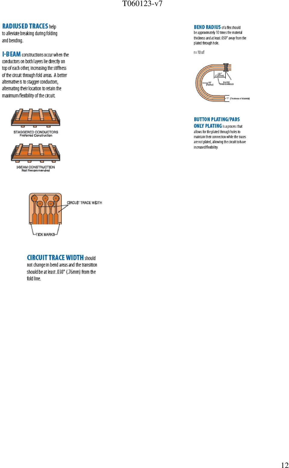
11 5 Flexible Circuit Board Connections An increasing number of connections are made with Kapton flexible circuit boards. This type of interconnection lends itself well to custom in-vacuum assemblies where cleanliness and reliability are paramount. Connection failures were encountered in the flexible circuit board assemblies used during the ELIGO upgrade to the OMC. The cause of the failures was traced to improper filleting of copper traces at the attachment point of square pads. Figure 11 shows the techniques that lead to reliable flexible circuit board designs. Figure 13 11

12 12
ISC Dual Frequency WFS RFPD Test Procedure:
 LASER INTERFEROMETER GRAVITATIONAL WAVE OBSERVATORY LIGO Laboratory / LIGO Scientific Collaboration LIGO 08 January 2013 ISC Dual Frequency WFS RFPD Test Procedure: Richard Abbott Distribution of this
CONEC SnapLock. 1 Introduction
 CONEC SnapLock E L E C T R O N I C C O N N E C T O R S 1 Introduction The new CONEC SnapLock locking system consists of D-SUB connectors and D-SUB hoods allowing quick and safe locking without any additional
HARTING. Electronic Connectors
 HARTING Electronic Connectors HARTING Electronic Connectors Global Innovative Technology The HARTING Technology Group has established a reputation for excellence and innovation with decades of experience
Directory chapter 04
 M Directory chapter 04 D-Sub Mixed subminiature D connectors New Page D-Sub mixed connector system general information................... 04.02 Contact arrangements............................................
LIGO- E040288-00-C 6/18/04. Installation of RFI Mitigated HEPI system at LLO
 LASER INTERFEROMETER GRAVITATIONAL WAVE OBSERVATORY -LIGO- CALIFORNIA INSTITUTE OF TECHNOLOGY MASSACHUSETTS INSTITUTE OF TECHNOLOGY LIGO- E040288-00-C 6/18/04 Installation of RFI Mitigated HEPI system
Amphenol C 091 A/B/D. Circular Connectors. Amphenol-Tuchel Electronics GmbH
 Amphenol C 091 A/B/D Circular Connectors Amphenol-Tuchel Electronics GmbH C 091 A Main Features Metal threaded coupling acc. to IEC. Number of contacts are 2 to 8, 12 and 14. Internal metal strain relief
Cabling Specifications
 APPENDIX A This appendix provides cabling and pinout information for feature cards on the Cisco AS5350XM and Cisco AS5400XM universal gateways. It contains the following sections: 2-Port and 4-Port T1
CIN::APSE MICROMINIATURE D-SUB
 INTRODUCTION CINCH has been producing filter connectors for years and has acquired an in depth knowledge of EMC protection. CINCH offers fast delivery on a wide range of standard filtered connectors and
Custom Cable Assemblies for Medical Applications and more.
 Custom Cable Assemblies for Medical Applications and more. National Cable Molding is one of the United States premier suppliers of custom molded electrical assemblies for medical applications. Our capability
Connectors, Adapters, and Tools
 MODEL NAME USE WITH: 213-CON Analog Output Connector 213 237-BAN-3 Triax to Banana Plug 7072, 7072-HV, 7172, 2001, DMMs 237-BNC-TRX 3-Lug Female Triax to Male BNC Connector with 237, 6517A, 7078-TRX cables
ISHIDA BC-3000. Scale to Scale Communications
 ISHIDA BC-3000 Scale to Scale Communications Setup Procedure & Operating Instructions March 2006 PN 94561 Revision History Date Page Description March 2006 Initial publication August 2006 2 Added RS-232
RS232/DB9 An RS232 to TTL Level Converter
 RS232/DB9 An RS232 to TTL Level Converter The RS232/DB9 is designed to convert TTL level signals into RS232 level signals. This cable allows you to connect a TTL level device, such as the serial port on
USB 3.1 Type-C and USB PD connectors
 USB 3.1 Type-C and USB PD connectors Presentation Introduction Purpose USB Type-C connectors Supplement to the USB 3.1 and Power Delivery specification Define USB 3.1Type-C receptacle, plug and cable assembly
I NTERFACE CABLE ADAPTER MODULE
 I NTERFACE CABLE ADAPTER MODULE The Interface Cable Adapter Module (ICAM) has two basic uses. First, it enables you to run shielded cable between the industrial sensor interface module (SIM) and the weather
Trident Connector Family Offers the Versatility and Reliability Required in Industrial & Transportation Applications
 Trident Connector Family Offers the Versatility and Reliability Required in Industrial & Transportation Applications Industrial and transportation applications require robust connections with superior
Options for ABB drives, converters and inverters. User s manual FDPI-02 diagnostics and panel interface
 Options for ABB drives, converters and inverters User s manual FDPI-02 diagnostics and panel interface Table of contents Table of contents 3 1. FDPI-02 diagnostics and panel interface Safety..............................................
POWER LOCK KIT GENERAL INSTALLATION -J04427 REV. 2007-12-04. Kit Number. Models. Additional Parts Required. Kit Contents
 -J0 REV. 00--0 POWER LOCK KIT GENERAL Kit Number -0, 0-0 Models For model fitment information, please see the P&A Retail Catalog or the Parts and Accessories section of www.harleydavidson.com (English
Connecting the Channel A
 20 Edge Lighting. All Rights Reserved. Installation Instructions for Cirrus Channel Suspension T, Tubular Lens w/2sq or 2RD Canopy IMPORTANT INFORMATION - This product is suitable for indoor locations.
INSTALLATION INSTRUCTIONS 160-Pin Cable for the NI PXI-2530B
 INSTALLATION INSTRUCTIONS 160-Pin Cable for the NI PXI-2530B Contents This guide describes how to connect and use the National Instruments 160-pin shielded cable for the NI PXI-2530B which has a maximum
430 Power/Electronics Replacement
 Replacing the main board WARNING Before proceeding, turn off the main power switch and unplug the power cord. Caution Make sure you are properly grounded with an ESD strap before continuing. The main printed
Sunny Boy Accessories SMA POWER BALANCER
 Sunny Boy Accessories SMA POWER BALANCER Installation Guide SBUS-PowBal-IUS102810 IMUS-SBUS-PBL Version 1.0 US SMA America, LLC Legal Restrictions Copyright 2010 SMA America, LLC. All rights reserved.
Directory chapter 02 - DIN Power (to 6 A) Types D, E, F, FM, 2F, F9, interface connectors I/U 02. 01. Technical characteristics types D and E... 02.
 Types D, E, F, FM, 2F, F9, interface connectors I/U 02. 01. Technical characteristics types D and E... 02.") Directory chapter 02 - () Types D, E, F, FM, 2F, F9, interface connectors I/U Page Technical characteristics types D and E.............................. 02.10 Type D connectors.................... 02.11
Directory chapter 02 - () Types D, E, F, FM, 2F, F9, interface connectors I/U Page Technical characteristics types D and E.............................. 02.10 Type D connectors.................... 02.11
P150SC15. Designed for 2015 Ford F150 Super-Cab and Super-Crew vehicles without Sony System. 2015 Stillwater Designs P150SC15-A2-20150813
 P150SC15 Designed for 2015 Ford F150 Super-Cab and Super-Crew vehicles without Sony System Subwoofer Assembly Amplifier Assembly Amplifier Harness 2015 Stillwater Designs P150SC15-A2-20150813 M6 Bolt M6
EDI Distributor Control Interface Wiring and Setup Instructions
 Universal I/O EDI Distributor Control Interface Wiring and Setup Instructions EDI UNIVERSAL I/O INTERFACE MODULE The only interface needed for EDI-V5 controls Network compatible with all older EDI controls
Advantium 2 Plus Alarm
 ADI 9510-B Advantium 2 Plus Alarm INSTALLATION AND OPERATING INSTRUCTIONS Carefully Read These Instructions Before Operating Carefully Read These Controls Corporation of America 1501 Harpers Road Virginia
Jack to Jack adapters Plug to Plug U-Link connectors PCB Right angle plastic PCB Right angle - metal. Ordering Codes
 BNC 75Ω RF CONNECTORS BNC 75Ω RF CONNECTORS To meet the need for higher performance, impedance matched cable interconnections, Amphenol offers a full line of 75 ohm BNC connectors. These connectors can
Cables. 1.888.KEITHLEY (U.S. only) www.keithley.com ACCESSORIES
 www.keithley.com ACCESSORIES") Model Description Type TERMINATIONS LENGTH From To m ft USE WITH: 236-ILC-3 Safety Interlock Shielded twisted pair 3-pin round 3-pin round 3 10 237, 4200-SCS, 8007, 8008 237-ALG-2 Low Noise Input Triax
Model Description Type TERMINATIONS LENGTH From To m ft USE WITH: 236-ILC-3 Safety Interlock Shielded twisted pair 3-pin round 3-pin round 3 10 237, 4200-SCS, 8007, 8008 237-ALG-2 Low Noise Input Triax
Elecraft K3 KPA3 Power Connector Replacement Revision A Review, April 16, 2012 Copyright 2012, Elecraft, Inc. All Rights Reserved
 Introduction Elecraft K3 KPA3 Power Connector Replacement Revision A Review, April 16, 2012 Copyright 2012, Elecraft, Inc. All Rights Reserved The connectors furnishing high current to the KPA3 module
RF Power Amplifier PA10W Owner s Manual SpinCore Technologies, Inc. http://www.spincore.com
 RF Power Amplifier PA10W Owner s Manual SpinCore Technologies, Inc. http://www.spincore.com Congratulations and thank you for choosing a design from SpinCore Technologies, Inc. We appreciate your business!
Pmod peripheral modules are powered by the host via the interface s power and ground pins.
 Digilent Pmod Interface Specification Revision: November 20, 2011 1300 NE Henley Court, Suite 3 Pullman, WA 99163 (509) 334 6306 Voice (509) 334 6300 Fax Introduction The Digilent Pmod interface is used
LIGO Mailing List Group Configuration
 LASER INTERFEROMETER GRAVITATIONAL WAVE OBSERVA- TORY LIGO Laboratory / LIGO Scientific Collaboration LIGO-T1200490-v2 LIGO Wednesday, October 31, 2012 LIGO Mailing List Group Configuration Warren G. Anderson
In regard to calculating system power requirements, refer to DBK Basics located near the front of this manual.
 DBK42 16-Slot 5B Signal Conditioning Module Overview 1 Hardware Setup 2 DBK42 Connection 2 DBK42 Configuration 2 5B Module Connection 2 Power Considerations 2 Terminal Block Connections 3 DaqBoard/2000
T1 Backhaul Connectivity Solution All Products :: Application Note
 Telect 1 RU Customer Interface Panel (CIP) Enables Demarcation, Remote Circuit Maintenance and Trouble Isolation at the Backhaul Node The Application: T1 Demarcation and Testing in Backhaul Environments
10/100BASE-T Copper Transceiver Small Form Pluggable (SFP), 3.3V 100 Mbps Fast Ethernet. Features. Application
, 3.3V 100 Mbps Fast Ethernet. Features. Application") Features Compliant with IEEE 802.3u standard Link distance at 100Mbps: up to 100m per IEEE802.3 EEPROM with serial ID functionality Detailed product information in EEPROM Industry standard small form pluggable
Features Compliant with IEEE 802.3u standard Link distance at 100Mbps: up to 100m per IEEE802.3 EEPROM with serial ID functionality Detailed product information in EEPROM Industry standard small form pluggable
General Information. Installation Wiring Practices for Vickers Electronic Products
 Vickers eneral Information Installation Wiring Practices for Vickers Electronic Products Revised 12/97 268 Installation Requirements Introduction Vickers Electronic Products are designed to be used in
Universal MATE-N-LOK Connectors
 Product Facts Pins and sockets can be intermixed in the same housing Positive polarization Rear cavity identification completely enclosed in housings Positive locking housings Insulation capability to.00
Electronic Circuit Construction:
 Electronic Circuit Construction: Various methods are used for building electronic circuits. The method that you choose depends on a number of factors, including the resources available to you and whether
Using Thermocouple Sensors Connecting Grounded and Floating Thermocouples
 Connecting Grounded and Floating Thermocouples For best performance, Thermocouple sensors should be floating. This will ensure that no noise currents can flow in the sensor leads and that no common-mode
LIEBERT VNSA Installation Sheet
 LIEBERT VNSA Installation Sheet Description The Liebert vnsa network switch is designed for connecting multiple Ethernet-ready devices and comes in various models. The unit may have: A Liebert icom display
What ensures easy and fast wiring?
 What ensures easy and fast wiring? SIMATIC TOP connect: the system cabling for connecting sensors and actuators to SIMATIC S7. Answers for industry. More efficient cabling made easy: SIMATIC TOP connect
ABB Drives. User s Manual. Pulse Encoder Interface Module RTAC-01
 ABB Drives User s Manual Pulse Encoder Interface Module RTAC-0 Pulse Encoder Interface Module RTAC-0 User s Manual 3AFE 64486853 REV A EN EFFECTIVE:.5.00 00 ABB Oy. All Rights Reserved. Safety instructions
UNBALANCED OUTPUT TO BALANCED INPUT WIRING METHODS
 MEASURING UNBALANCED DEVICES USING THE SIM-0 AUDIO ANALYZER audio devices and/or sources must sometimes be used within a sound reinforcement system, and integrated with balanced inputs and outputs. These
ABB Drives. User s Manual HTL Encoder Interface FEN-31
 ABB Drives User s Manual HTL Encoder Interface FEN-31 HTL Encoder Interface FEN-31 User s Manual 3AUA0000031044 Rev B EN EFFECTIVE: 2010-04-06 2010 ABB Oy. All Rights Reserved. 5 Safety instructions
DMX512 TO 0-10 VOLT ANALOG CONVERTER OWNERS MANUAL
 DMX512 TO 0-10 VOLT ANALOG CONVERTER OWNERS MANUAL Doug Fleenor Design 396 Corbett Canyon Road Arroyo Grande, CA 93420 (805) 481-9599 revision 2.1 November, 1998 PRODUCT DESCRIPTION The DMX512 to Analog
Cable Testing with the Huntron Tracker Model 30 and Scanners
 Cable Testing with the Huntron Tracker Model 30 and Scanners Huntron Tracker Model 30 with Scanner 31S Testing 64 pin ribbon cable with LED array fixture Introduction The combination of Huntron Tracker
USER GUIDE. Studio Hotline Multi-line System Phone Flasher and Door/Alert Indicator Input Module and Indicator. DM Engineering. Version 1.
 USER GUIDE Studio Hotline Multi-line System Phone Flasher and Door/Alert Indicator Input Module and Indicator Version 1.3 DM Engineering 2174 Chandler St. Camarillo, CA 91345-4611 805-987-7881 800-249-0487
HARAX circular connector
 Show navigation HARAX circular connector Technical characteristics Specifications IEC 60 352-4 IEC 60 9475-2 Approvals HARAX M8-S/M12-S Rated voltage Rated current Diameter of individual strands Conductor
AmphenolR. Now you're connected!
 Table of Contents CoolPower Overview... Page 3 CoolPower Slim Drawer - DW Series... Page 4 CoolPower D-Sub - LCC17 Series... Page 7 Amphenol Power Solutions... Page 9 Other Amphenol Commercial Products...
Data sheet GIOD.1 Input/output module with CAN bus. ERP no.: 5204183. www.guentner.de. Data sheet GIOD.1 V_3.0
 Data sheet GIOD.1 Input/output module with CAN bus ERP no.: 5204183 www.guentner.de Page 2 / 10 Contents 1 GIOD.1... 3 1.1 Functional description...3 1.2 Connections... 5 1.3 Electrical properties of...
MICRO SFP+ CONNECTOR & CABLE ASSEMBLY
 MICRO SFP+ CONNECTOR & CABLE ASSEMBLY micro SFP+ Connector and Cable Assembly TE Connectivity s (TE) micro SFP+ connector and cable assembly empower you to dream big when designing your communication system.
CAUTION! THE 7I29 USES VOLTAGE AND POWER LEVELS THAT REPRESENT A HAZARD TO LIFE AND LIMB.
 7I29 MANUAL Rev 1.5 CAUTION! THE 7I29 USES VOLTAGE AND POWER LEVELS THAT REPRESENT A HAZARD TO LIFE AND LIMB. THE 7I29 IS INTENDED FOR USE BY OEMS THAT WILL INTEGRATE IT INTO A SYSTEM WITH INTERLOCKS AND
Owners & Installation Manual for the Sheridan, Mountainair, Pine Valley and Old Forge Ceiling Fan Family
 Owners & Installation Manual for the Sheridan, Mountainair, Pine Valley and Old Forge Ceiling Fan Family Part of the Kiva Lighting Family Custom Lighting and Fans Since 1992 1312 12th St NW Albuquerque,
Quick Reference Guide 1.5 mm AMP Mini CT Connector Series
 Quick Reference Guide The AMP Mini CT connectors are miniature wire-to-board and wire-to-wire connectors. Like the standard AMP CT connector series, these connectors are tailored for improved harness productivity
CITY OF LOS ANGELES CALIFORNIA
 BOARD OF BUILDING AND SAFETY COMMISSIONERS VAN AMBATIELOS PRESIDENT E. FELICIA BRANNON VICE-PRESIDENT JOSELYN GEAGA-ROSENTHAL GEORGE HOVAGUIMIAN JAVIER NUNEZ CITY OF LOS ANGELES CALIFORNIA ERIC GARCETTI
PAM Connectors. PAM Bayonet Connectors
 PAM Bayonet Tel : 33 (0)1 60 84 21 40 Fax : 33 (0)1 60 84 43 81 info@bernier.tm.fr www.bernier.tm.fr Overview Miniature audio connectors with bayonet locking system, equipped with 07 or 10 contacts, and
Applied Electronics. Commercial Dimming System UPDATE NOTICE
 REV. A Applied Electronics Commercial Dimming System UPDATE NOTICE This notice is to inform the end user of an additional feature added to this DP12/2400 dimming unit. This unit has been outfitted with
PRODUCT SPECIFICATION
 ipass TM / ipass+ TM 0.8 mm PITCH I/O CONNECTOR SYSTEM EXTERNAL ipass / ipass+ of TABLE OF CONTENTS.0 SCOPE... 3.0 PRODUCT DESCRIPTION... 3. PRODUCT NAME AND SERIES NUMBER(S)... 3. DIMENSION, MATERIALS,
INSTALLATION INSTRUCTIONS
 LIGHTING CONTROL PANELS 4 AND 8 RELAYS INSTALLATION INSTRUCTIONS INSTALLATION OVERVIEW The installation instructions contained in this document are provided as a guide for proper and reliable installation.
Glenair Military and Industrial Power and Signal Connectors
 Glenair Military and Industrial Power and Signal Connectors Series ITS (And FRITS) 5015 Type Reverse Bayonet Connectors Derived from MIL-DTL-5015 and VG95234 Mating mechanism (3 reverse bayonets at 120
Trigno/Vicon System Integration
 Delsys and Vicon Analog Integration Motion capture systems will often have the ability to sample analog data channels as a convenient means for synchronizing external data streams with motion capture data.
Part Name/Description Part Number Quantity. Power Cable 4000950-5 1
 Note: Indented items indicate parts included in an assembly listed above Part Name/Description Part Number Quantity Power Cable 4000950-5 1 Raven Harness Adapter Kit 4100525 1 Installation Instructions
14 PHOENIX CONTACT Courtesy of Power/mation. 1310 Energy Lane, Saint Paul, MN 55108. info@powermation.com - 800-843-9859 - www.powermation.
 14 PHOENIX CONTACT PLUSCON circular is a circular connector for use in industrial automation. The range of design sizes available is varied, starting with the design sizes M5 to M8 and M1, for sensor/actuator
GLOLAB Universal Telephone Hold
 GLOLAB Universal Telephone Hold 1 UNIVERSAL HOLD CIRCUIT If you have touch tone telephone service, you can now put a call on hold from any phone in the house, even from cordless phones and phones without
Physical. Electrical. Environmental. Insulation: Contact: Plating: Temperature Rating: -55 C to +85 C
 M I/O Interconnect System 2.0 mm for IEEE 194 Wiremount Receptacle (Female) E206 Series Designed to mate to all M I/O Interconnect System 2.0 mm for IEEE 194 Boardmount Plugs Polarized to provide proper
The Do s and Don ts of Pressure Transducers
 The Do s and Don ts of Pressure Transducers ABSTRACT When specifying a pressure transducer for a process measurement, a number of items have to be considered. Some of the more important ones are discussed
K-Type Thermocouple Sensor User s Guide
 K-Type Thermocouple Sensor User s Guide 1 TABLE OF CONTENTS: 1 INTRODUCTION... 2 2 TYPICAL APPLICATION:... 2 3 INSTALLATION RULES:... 2 3.1 Connecting the sensor to M1/MD4 data logger:... 2 3.2 Connecting
Replacing N-300 PCB. 2014 YZ Systems for use by YZ s distribution network and end-users. www.yzsystems.com
 Replacing N-300 PCB Replacing N-300 PCB Record all Parameters and other operational information from The N-300 if Possible for Use in Programing The new PCB. If Parameters are not Obtainable from The Old
LocoNet, the Digitrax Difference
 LocoNet, the Digitrax Difference LocoNet is Digitrax's method of communication between LocoNet compatible devices on a model railroad layout. LocoNet Compatible devices are designed to work together on
16/32 Channel 1U Rack Mount CCTV Power Supply
 16/32 Channel 1U Rack Mount CCTV Power Supply Manual PH-A3224-GUQ Shown 16-Channel 32-Channel PTC PH-A1612-PUQ PH-A3224-PUQ Glass Fuse PH-A1612-GUQ PH-A3224-GUQ Industrial design 12 Amp 3 Amps per channel
DC Series Digital Conversion Alarm Operator s Manual
 DC Series Digital Conversion Alarm Operator s Manual Ver. 2012 - Rev. 1004 Class 1 Inc. design manufacture installation service world class innovation Call us for your next project. Area Alarm Conversion
PowerFlex 700H and 700S AC Drives Frame 11 Main Fan Capacitor Replacement Kit
 Installation Instructions PowerFlex 700H and 700S AC Drives Frame 11 Main Fan Capacitor Replacement Kit ATTENTION: The sheet metal cover and mounting screws on the ASIC Board located on the power structure
Sealed Industrial Ethernet Circular IP67 Cat. 5e RJ45 Connector System
 Revised Sept--22-2009 Sealed Industrial Ethernet Circular IP67 Cat. 5e RJ45 Connector System Description The sealed circular RJ45 connector system is designed for use in harsh environments. The connector
SERVO CONNECTIONS FOR OLDER BOARDS
 What s a Microcontroller v3.0 Suppliment to Chapter 7, Activity #1 SERVO CONNECTIONS FOR OLDER BOARDS This document explains how to connect servo and LED indicator circuits to the older revisions of the
Universal Vehicle Power Supply 9007AX01. Installation Instructions
 Universal Vehicle Power Supply 9007AX01 Installation Instructions Disclaimer Honeywell International Inc. ( HII ) reserves the right to make changes in specifications and other information contained in
Arecont Vision H.264 Color or Day/Night SurroundVideo Series Installation Manual
 0 P a g e H.264 Color or Day/Night SurroundVideo Installation Manual Inside the box: A. Arecont Vision SurroundVideo camera B. Mounting template C. RJ45 female to female coupler D. Hex key E. Security
Elma Bustronic VPX Test Extender User Manual
 Elma Bustronic VPX Test Extender User Manual Elma Bustronic used creative engineering to solve a major problem in developing the VPX Extender Board - the lack of a right angle receptacle for VPX in the
DVI DA2 and DVI DA 4 User Guide
 DVI DA2 and DVI DA 4 User Guide This guide describes the installation and operation of the Extron DVI DA2 and DVI DA4 Distribution Amplifiers. Unless stated otherwise, distribution amplifier or the unit
EMBEDDED ACCESS CONTROL Hardware Installation Guide
 EMBEDDED ACCESS CONTROL Hardware Installation Guide Lenel goentry Hardware Installation Guide, product version 1.00. This guide is item number DOC- ENHW-ENU, revision 1.003, April 2009 Copyright 2009 Lenel
How To Wire Wireline Cable To A Cell Phone (New Zealand)
") Installation Guide EnerNOC Site Server - S2 Installation Guide - AUS, NZ v 1.7 EnerNOC New Zealand Limited 2 Collina Terrace PO Box 12-202 Thorndon Wellington NZ 6144 +64 4 909 7546 1 Table of Contents
Installation Guide EnerNOC Site Server - S2 Installation Guide - AUS, NZ v 1.7 EnerNOC New Zealand Limited 2 Collina Terrace PO Box 12-202 Thorndon Wellington NZ 6144 +64 4 909 7546 1 Table of Contents
Installation & Weatherproofing Guide for ENCOM Broadband Radios
 Installation & Weatherproofing Guide for ENCOM Broadband Radios Read the following instructions before proceeding with your ENCOM Wireless Radio installation. Keep these instructions in safe location for
CoolWave r 2 Phase Control Board and Cable Replacement Kits
 Instruction Sheet P/N 1102452A CoolWave r 2 Phase Control Board and Cable Replacement Kits Two kits are available to replace the CoolWave 2 phase control board: S S Phase Control Board and Cable Kit (required
Document number RS-PRD-00130 Revision 05 Date 20/10/2009 Page 1/30
 Date 20/10/2009 Page 1/30 1. Purpose This document describes the field replacement of the footscan plate cable for these models: 2m hi-end plate SN 11/5/xxx 2m pro plate SN 7/5/xxx 0.5m 2003 hi-end plate
LED...A70..4-..Q Series Sealed High-Intensity
 LED...A70..4-..Q Series Sealed High-Intensity Area Lights High-Power Lighting for use with PresencePLUS and Other Vision Systems Features Rugged, waterproof housing, rated IEC IP68 Compact area light for
omega.com ΩOMEGA RS232 Multi-Drop www.omega.com FMA1600-MDB Multi-Drop Box
 omega.com ΩOMEGA RS232 Multi-Drop www.omega.com FMA1600-MDB Multi-Drop Box 1 3/29/2010 Rev.0 DOC-OMEGABB9MAN 2 Introduction FMA1600-MDB Multi-Drop Box Operating Bulletin The FMA1600-MDB Multi-Drop Box
ReachFree ID Installation Instructions For Portal TI, Sentinel and C-Start. Unitec www.startwithunitec.com
 ReachFree ID Installation Instructions For Portal TI, Sentinel and C-Start Unitec www.startwithunitec.com Proprietary Information and Materials of Unitec, Inc. Such proprietary information and materials
POWER WAVE 455M/STT & (CE)
") Illustration of Sub Assemblies Illustration of Sub Assemblies Illustration of Sub Assemblies Illustration of Sub Assemblies P-450 P-450 PARTS LIST FOR POWER WAVE 455M/STT & (CE) P-450-A P-450-A ILLUSTRATION
Illustration of Sub Assemblies Illustration of Sub Assemblies Illustration of Sub Assemblies Illustration of Sub Assemblies P-450 P-450 PARTS LIST FOR POWER WAVE 455M/STT & (CE) P-450-A P-450-A ILLUSTRATION
Upgrading a GainMaker Line Extender from a Line-Powered Source to a 120 V AC-Powered Source Installation Instructions
 Upgrading a GainMaker Line Extender from a Line-Powered Source to a 120 V AC-Powered Source Installation Instructions Overview Audience These installation instructions are intended for all cable system
INSTALLATION INSTRUCTIONS
 Rear Vision System Tailgate Handle Camera Mirror Display 2004-2014 Ford F-150 and 2008-2015 Ford Super Duty (Kit part numbers 9002-9521) Kit Contents: Mirror Tailgate Handle with camera and harness Interior
Metallized Particle Interconnect A simple solution for high-speed, high-bandwidth applications
 Metallized Particle Interconnect A simple solution for high-speed, high-bandwidth applications The MPI Material Advantage Advantages: High-Density - Scalable Pitches down to 0,8 mm pitch possible - Scalable
RC2200DK Demonstration Kit User Manual
 Demonstration Kit User Manual Table of contents TABLE OF CONTENTS... 1 QUICK INTRODUCTION... 2 INTRODUCTION... 3 DEMONSTRATION BOARD... 4 POWER SUPPLY SECTION... 5 RS-232 INTERFACE... 6 CONNECTORS... 7
Acceptability of Printed Circuit Board Assemblies
 Section No.: 12I.2.3, Sheet 1 of 9 Rev Level: 16 Additional Distribution: PCB Assembly Subcontractors 1.0 Purpose 2.0 Scope Acceptability of Printed Circuit Board Assemblies 1.1 The purpose of this standard
CutMaster 102. 6.04 Major External Replacement Parts
 CutMaster 0 6.04 Major External Replacement Parts Item # Qty Description Catalog # Cover with labels 9-08 Base Enclosure Assembly 9-086 Tube, roll handle 9-0 4 Front Panel 9-087 Rear Panel 9-00 4 Art #
MAC-8. Technical Documentation AC Voltage Input Submodule. Please keep for further use!
 MAC-8 Technical Documentation AC Voltage Input Submodule Please keep for further use! Edition date/rev. date: 16.12.1998 Document no./rev. no.: TRS - V - BA - GB - 0029-00 Software version: 1.0 File name:
Lighting Controls ! WARNING RISK OF ELECTRIC SHOCK. Installation Instructions DESCRIPTION
 GE Lighting Installation Instructions Lighting Controls Centralized Lighting Control Panel Interior Catalog Number CLCINTxx DESCRIPTION The Centralized Lighting Control System is a small network of relay
Quick Reference Guide 1.5 mm AMP Mini CT Connector Series
 Quick Reference Guide 1.5 mm AMP Mini CT Connector Series The AMP Mini CT connectors are miniature wire-to-board and wire-to-wire connectors. Like the standard AMP CT connector series, these connectors
Cable Specifications. T3 Trunk Cabling APPENDIX
 APPENDIX B This appendix contains details on the MGX 8230 cabling. It includes the following sections: T3 Trunk Cabling Frame Relay Cabling DC Power Cabling AC Power Cabling Control and Clock Cabling External
Mobile Device Power Monitor Battery Connection Quick Start Guide
 Mobile Device Power Monitor Battery Connection Quick Start Guide Distributed By: Monsoon Solutions, Inc. www.msoon.com Introduction The Power Tool software and the Mobile Device Power Monitor hardware
The power module is Feature Number 8800-F2-901.
 Hotwire 8820 GranDSLAM AC to DC Power Supply Installation Instructions Document Number 8800-A2-GZ41-00 AC to DC Power Supply The AC to DC Power Supply consists of a power supply chassis and one or two
KEYLESS ENTRY UPGRADE SECURITY SYSTEM for 2004 TOYOTA HIGHLANDER
 KEYLESS ENTRY UPGRADE SECURITY SYSTEM for 2004 TOYOTA HIGHLANDER DEALER SERVICE AND INSTALLATION MANUAL KIT NO. 00016-30915 Contents PARTS LIST... 2 PARTS ILLUSTRATIONS... 2 VEHICLE PREPARATION... 3 INSTALLING