INSTALLATION & OPERATION MANUAL
|
|
|
- Erick Barrie Merritt
- 7 years ago
- Views:
Transcription
1 INSTALLATION & OPERATION MANUAL HB6PAKX & HB6PAKXX HIDE-A-BLAST STANDARD HIDE A BLAST UNIT HB6PAK-PI-X NGPI TWIST LOCK HIDE-A-BLAST LED WARNING LIGHT NGPI TWIST LOCK HIDE A BLAST UNIT IMPORTANT: 6 LED WARNING LIGHT Read all instructions and warnings before installing and using. INSTALLER: This manual must be delivered to the end user of this equipment.

2 Introduction The HB Series LED light represents the latest in state-of-the-art LED warning technology. The latest in MOSFET technology and advanced design provide efficient operation, superior performance, reliability and long life. The use of microprocessor control allows the HB Series to offer more light pattern options and versatility than any other remote system available. The user may select Single, Double, Triple, Quad, Variable Flash, Double-Double or Triple Flash Patterns. Standard Features The HB Series HIDE-A-BLAST LED light is available in a single unit package complete with installation instructions. Multiple HB Series LED Lights can be connected together and operated from the same control switch. All HB Series LED Lights have the following features: 12 OR 24 VDC OPERATION REVERSE POLARITY PROTECTED MULTIPLE USER SELECTABLE FLASH PATTERNS See Flash Pattern Selection, page 6. Note: A user supplied fuse must be installed in series with the red wire. Install the fuse near the power source. The fuse should be sized to the nearest standard size fuse that is approximately 125% of the combined total current of all HB Series LED Lights installed on the circuit. As an example, two HB Series LED Lights should be fused at 3A for 12VDC operation, 1A for 24V operation. Specifications MODEL VARIANTS: HB6PAKX & HB6PAKXX = 6 LEDs X denotes the LED color, Red, Blue, Amber or White (R, B, A or W) and dual color combinations of Amber/White, Red/Blue, Red/White or Blue/White (AW, BR, RW or BW). i.e. HB6PAKW has six white LEDs. MECHANICAL SPECIFICATIONS: CABLE LENGTH: 15 feet DIMENSIONS: See figure A BOXED WEIGHT: 0.9lb UNBOXED WEIGHT: 0.8lb LED COLOR: Red, Blue, Amber or White (mixing of colors in the same unit is not supported) LENS COLOR: clear ELECTRICAL SPECIFICATIONS: OPERATING VOLTAGE & POLARITY: 11-30VDC, Neg or Pos ground AVERAGE CURRENT: 13.8VDC OPERATING TEMPERATURE: -30 to 150 F INPUT POWER: 8W OPERATING MODES: Synchronous and Non-Synchronous

3 WARNING! The use of this or any warning device does not ensure that all drivers can or will observe or react to an emergency warning signal. Never take the right-of-way for granted. It is your responsibility to be sure you can proceed safely before entering an intersection, driving against traffic, responding at a high rate of speed, or walking on or around traffic lanes. The effectiveness of this warning device is highly dependent upon correct mounting and wiring. Read and follow the manufacturer s instructions before installing or using this device. The vehicle operator should insure daily that all features of the device operate correctly. In use, the vehicle operator should insure the projection of the warning signal is not blocked by vehicle components (i.e.: open trunks or compartment doors), people, vehicles, or other obstructions. This equipment is intended for use by authorized personnel only. It is the user s responsibility to understand and obey all laws regarding emergency warning devices. The user should check all applicable city, state and federal laws and regulations. Code 3, Inc., assumes no liability for any loss resulting from the use of this warning device. Proper installation is vital to the performance of this warning device and the safe operation of the emergency vehicle. It is important to recognize that the operator of the emergency vehicle is under psychological and physiological stress caused by the emergency situation. The warning device should be installed in such a manner as to: A) Not reduce the output performance of the system, B) Place the controls within convenient reach of the operator so that he can operate the system without losing eye contact with the roadway. Emergency warning devices often require high electrical voltages and/or currents. Properly protect and use caution around live electrical connections. Grounding or shorting of electrical connections can cause high current arcing, which can cause personal injury and/or severe vehicle damage, including fire. Any electronic device may create or be affected by electromagnetic interference. After installation of any electronic device operate all equipment simultaneously to insure that operation is free of interference. Never power emergency warning equipment from the same circuit or share the same grounding circuit with radio communication equipment. All devices should be mounted in accordance with the manufacturer's instructions and securely fastened to vehicle elements of sufficient strength to withstand the forces applied to the device. Driver and/or passenger air bags (SRS) will affect the way equipment should be mounted. This device should be mounted by permanent installation and within the zones specified by the vehicle manufacturer, if any. Any device mounted in the deployment area of an air bag will damage or reduce the effectiveness of the air bag and may damage or dislodge the device. Installer must be sure that this device, its mounting hardware and electrical supply wiring does not interfere with the air bag or the SRS wiring or sensors. Mounting the unit inside the vehicle by a method other than permanent installation is not recommended as unit may become dislodged during swerving, sudden braking or collision. Failure to follow instructions can result in personal injury. PROPER INSTALLATION COMBINED WITH OPERATOR TRAINING IN THE PROPER USE OF EMERGENCY WARNING DEVICES IS ESSENTIAL TO INSURE THE SAFETY OF EMERGENCY PERSONNEL AND THE PUBLIC. Unpacking and Pre-installation Remove the product from the box and examine the unit for any shipping damage. Report any damage to the carrier immediately. Inspect the contents to be certain that the following items are included: A. 1 HB6PAK Series LED Light with 15 ft. Cable B. 1 Installation Manual 3

4 Installation and Mounting 1. First, carefully plan the installation so that the HB Series LED Lights will not interfere with the mounting or operation of the vehicle's existing light fixtures. Using a 1 inch hole saw, cut a hole in the vehicle's light fixture in a location that will allow the HB Series LED light to be mounted in such a way that it will provide maximum light inside the reflector (see Figure B). Use a deburring tool to remove burrs and to chamfer the edge of the hole before inserting the HB6PAK. Proper installation will provide an excellent seal and prevent water from entering the light fixture. Wiring FIGURE A 1. Install the LED light heads in the desired locations. 2. Route the cables between the light heads and the control switch panel. Make sure the cable is secure along the chosen routing inside the vehicle to prevent damage by chafing or binding. Be sure to keep the cables away from engine hot spots. 3. Secure the cables and the HB Series flasher module using plastic wire ties.! WARNING! The HB Series LED Light components are water resistant but NOT waterproof and should be located in an area protected from the weather and water. 4

5 4. For synchronized operation of multiple HB Series lights the yellow wires from each unit's cable must be connected together. Insulate this connection using an insulated butt splice to prevent accidental contact with power or ground. Connections: Red +Power (11-30VDC) Black Ground Yellow Synchronization Blue Pattern Selection The HB6PAK light should be fully inserted into the hole so that the aluminum heatsink is against the light housing and the grove of the rubber seal is locked into the hole. This will provide a secure installation and a highly water resistant seal. FIGURE B IMPORTANT: To extend the power (+) and ground (-) wires, use the following as a guide. 1 to 10 ft. use 20AWG wire 10 to 50 ft. use 18AWG wire Pattern Selection Timing Time Function 0~1 sec NEXT PATTERN / ON 1~3 sec PREVIOUS PATTERN 3~5 sec P19 CYCLE FLASH >5 sec OFF 5

6 FLASH PATTERN SELECTION FLASH MODE Any one of the 20 Flash Patterns may be selected by using the blue wire to scroll through the patterns. Touch the blue wire to ground for about 1 second and then remove it. The flash pattern will switch to the next pattern. When the yellow wires (SYNC) from each light are connected, lights with Phase 1 patterns selected will flash in an alternating sequence with lights that have a Phase 2 pattern selected. The following patterns are available. Description 1. signal alert alternating (Factory Default) 2. signal alert simultaneous phase1 3. signal alert simultaneous phase2 4. rapid flash alternating 5. rapid flash simultaneous phase1 6. rapid flash simultaneous phase2 7. single flash 75 alternating 8. single flash 75 simultaneous phase1 9. single flash 75 simultaneous phase2 10. single flash 375 alternating 11. single flash 375 simultaneous phase1 12. single flash 375 simultaneous phase2 13. action flash alternating 14. action flash simultaneous 15. modul flash alternating 16. modul flash simultaneous 17. action scan 18. STEADY 19. Cycle Flash 20. off 1. Connect the Power/Control wire harness assembly to a switch. To select one of the 30 different flash functions, turn the light on and touch the bare end of the blue wire to ground for about one second. You can also scroll backward through the flash pattern table (see the PATTERN SELECTION TIMING section for complete details. Repeat this process until you reach the desired flash pattern. After you have selected the desired flash pattern, you should cover the bare end of the blue wire with heat shrinkable tubing to prevent an ac- 6
 2. signal alert simultaneous phase1 3. signal alert simultaneous phase2 4. rapid flash alternating 5.")
7 cidental pattern change or short circuit. The flash pattern may also be selected remotely by the operator by connecting the blue wire to the ground through a Normally Open (NO) Momentary Push Button Switch. For synchronized simultaneous flashing, set all HB Series LED lights to a Phase 1 flash pattern. For synchronized - alternating flashing, set a Phase 1 pattern on one HB Series LED light and a Phase 2 pattern on the other unit. The factory default flash pattern may be restored by holding the blue wire to ground for 3~5 seconds. MAINTENANCE The HB Series LED light has been designed to provide trouble free service. In case of difficulty, refer to the Troubleshooting section. Periodic inspection of product's wiring connections for shorted or open wires will assure trouble free operation. The primary cause of short circuits has been found to be wires passing through firewalls, roofs, etc. Troubleshooting NOTE: DO NOT TAMPER WITH THE LED OR FLASHER MODULES. THIS PRODUCT IS SOLD AS A COMPLETE SYSTEM, AND IS NOT DESIGNED FOR FIELD REPAIR. ANY ATTEMPT TO DISASSEMBLE THE PRODUCT WILL VOID THE WARRANTY. All HB Series LED lights are thoroughly tested before shipment. However, should you encounter a problem during installation or during the life of the product, refer to the guide below for information on troubleshooting. In most cases problems that occur will be related either to the power/control wiring. PROBLEM External fuse blows Light heads do not flash TROUBLESHOOTING GUIDE 1. Power input wires shorted 2. Incorrect fuse size 3. Flasher Module Failed 1. Wire connections loose at switch panel or power source 2. Cable to light heads damaged and shorting to chassis SOLUTION 1. Check power connections 2. Replace with correct size fuse 3. Return for Service 1. Check all connections 2. Isolate damaged cable by disconnecting and reconnecting outputs one at a time. Repair the damaged cable. 3. Flash Pattern is set to OFF 3. Select valid flashing pattern Incorrect flash pattern 1. Wrong Flash Pattern is selected. 1. See FLASH PATTERN SELECTION. Flash patterns change continuously 1. Unit is in CYCLE FLASH mode. Proper operation. 1. This is normal operation for this mode. If CYCLE FLASH MODE is not desired see FLASH PATTERN SELECTION. 7

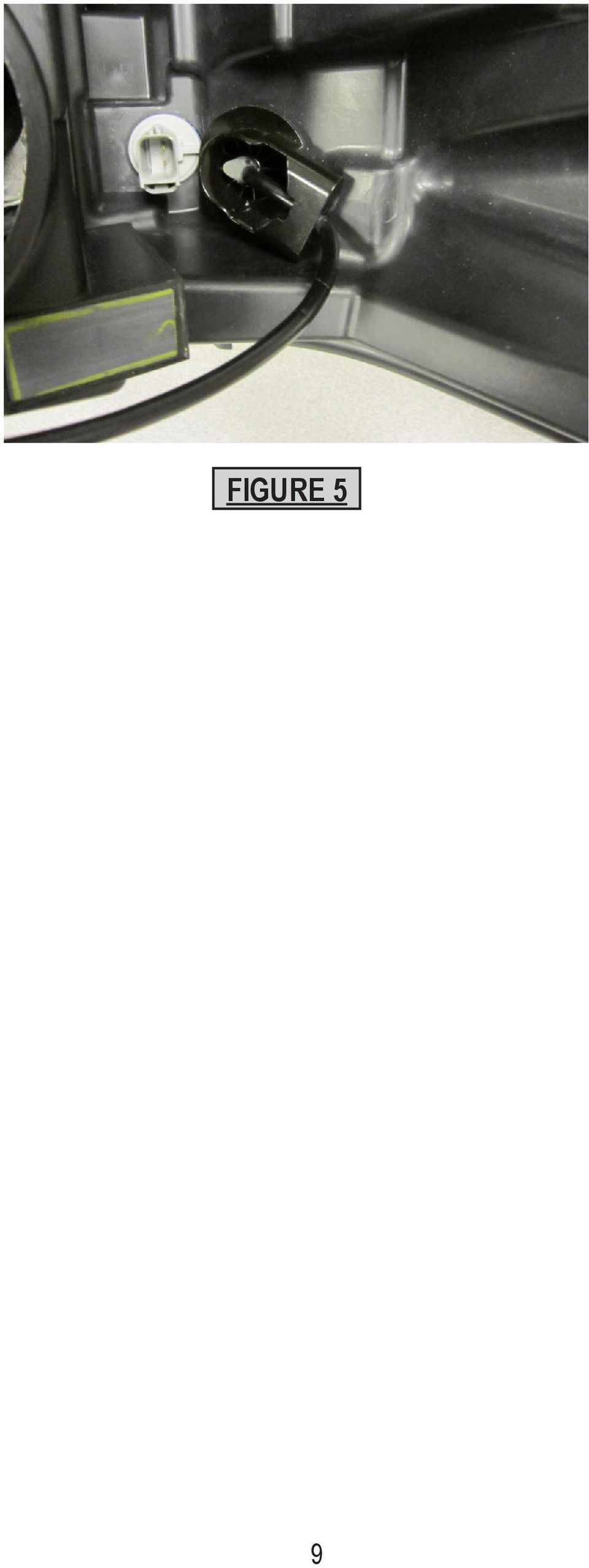
8 Installation & Mounting-NGPI Twist Lock Version Step-1. Locate the NGPI light bulb plug (see Figure 1). Step-2. Remove the NGPI light bulb plug by rotating it counter clockwise until the bulb plug relsases (see Figure 2). Step-3. Take note of the positions of the retention cam clearance notches and Insert the Twist Lock Hide A Blast unit so that the retention cams fit through the holes in the NGPIs headlight assembly (see Figure 3 and then 4). Step-4. Rotate the Twist Lock Hide A Blast Unit clockwise as far as it goes to lock it into place in the NGPI headlight housing (see Figure 5 page 9) FIGURE 1 FIGURE 2 FIGURE 3 FIGURE 4 8
. Step-4.")
9 FIGURE 5 9
10 NOTES: 10

11 NOTES: 11

12 WARRANTY This product was tested and found to be operational at the time of manufacture. Provided this product is installed and operated in accordance with the manufacturer's recommendations, Public Safety Equipment guarantees the HB Series LED Light for a period of 5 years from the date of purchase or delivery, whichever is later. Units demonstrated to be defective within the warranty period will be repaired or replaced at the factory service center at no cost. Improper installation or use of inappropriate or inadequate wiring or circuit protection causes this warranty to become void. Failure or destruction of the product resulting from abuse or unusual use and/or accidents is not covered by this warranty. Use of non-pse components and assemblies may cause damage to the system and/or personal injury, and voids all warranties on PSE systems and components. PSE shall in no way be liable for other damages including consequential, indirect or special damages whether loss is due to negligence or breach of warranty. PSE MAKES NO OTHER EXPRESS OR IMPLIED WARRANTY INCLUDING, WITHOUT LIMITATION, WARRANTIES OF FITNESS OR MERCHANTABILITY, WITH RESPECT TO THIS PRODUCT. PRODUCT RETURNS In order to provide you with faster service, if you are going to return a product for repair or replacement*, please contact our factory to obtain a Return Goods Authorization Number (RGA number) before you ship the product to PSE. Write the RGA number clearly on the package near the mailing label. Be sure you use sufficient packing materials to avoid damage to the product being returned while in transit. *PSE reserves the right to repair or replace product at its discretion. PSE assumes no responsibility or liability for expenses incurred for the removal and/or reinstallation of products requiring service and/or repair. For Technical Support / Service, please call Public Safety Equipment, Inc N. Warson Road St. Louis, Missouri USA Ph. (314) Fax (314) Code 3 is a registered trademark of Public Safety Equipment, Inc. a subsidiary of Public Safety Equipment, Inc. CycleFlash is a trademark of Public Safety Equipment, Inc. Revision 1, 10/12- Instruction Book Part No. T Public Safety Equipment, Inc. Printed in USA

LED NarrowStik LED LC-Stik
 INSTALLATION & OPERATION MANUAL NASL547/39 NASL847/39 NAS3547/39 NAS3847/39 NarrowStik LCC547/39 LC847/39 LC-Stik LC-STIK NARROWSTIK 3-Up OPTIX TM NARROWSTIK LED NarrowStik LED LC-Stik Contents: Introduction
INSTALLATION & OPERATION MANUAL LED
 INSTALLATION & OPERATION MANUAL LED Duo Beam TM Introduction... 2 Lightbar Unpacking & Pre-Installation... 2 Installation & Mounting... 3 Wiring Instructions... 4 Maintenance... 4 Flash Pattern Selection...
SERIES 45, 65, 85 LED PERIMETER, STOP/TURN/TAIL INSTALLATION & OPERATION MANUAL IMPORTANT: LED PERIMETER, STOP/TURN/TAIL SERIES 45, 65, 85
 INSTALLATION & OPERATION MANUAL LED PERIMETER, STOP/TURN/TAIL SERIES 45, 65, 85 SERIES 45, 65, 85 Contents: LED PERIMETER, STOP/TURN/TAIL Introduction... 2 Unpacking & Pre-Installation... 2 Mounting Options...
Installation Instructions
 520 Installation Instructions Thank you very much for purchasing PIAA product. Please read this entire manual before installation and use of this product. For Installers Please give this Installation Manual
2. Remove rear cover of head lamp if bulbs are covered/sealed within the housings, and remove halogen bulb carefully.
 These instructions are designed to address most general installation procedures across vehicles and should not be considered vehicle make, model or year specific. Please contact the vendor directly for
Advantium 2 Plus Alarm
 ADI 9510-B Advantium 2 Plus Alarm INSTALLATION AND OPERATING INSTRUCTIONS Carefully Read These Instructions Before Operating Carefully Read These Controls Corporation of America 1501 Harpers Road Virginia
VEHICLE THEFT/SECURITY SYSTEMS
 DN VEHICLE THEFT/SECURITY SYSTEMS 8Q - 1 VEHICLE THEFT/SECURITY SYSTEMS TABLE OF CONTENTS page GENERAL INFORMATION INTRODUCTION...1 VEHICLE THEFT SECURITY SYSTEM....1 ENABLING...1 ARMING...1 DISARMING...2
UNIVERSAL LUMBAR INSTALLATION INSTRUCTIONS
 UNIVERSAL LUMBAR INSTALLATION INSTRUCTIONS CONTENTS Parts List... 2 Parts Diagram... 2 Helpful Hints... 3 Installation... 4 Operation and Troubleshooting Guide... 6 Warranty Information... 8 Form #3132,
EVANS ELECTRONIC TEMPERATURE CONTROL TROUBLESHOOTING GUIDE for systems equipped with electric coolant valve and external PC board.
 EVANS ELECTRONIC TEMPERATURE CONTROL TROUBLESHOOTING GUIDE for systems equipped with electric coolant valve and external PC board. This Troubleshooting Guide covers the electric coolant valve and control
RI-215A Operator s Manual. Part Number: 71-0045RK Revision 0 Released: 10/3/05
 RI-215A Operator s Manual Part Number: 71-0045RK Revision 0 Released: 10/3/05 Warranty RKI Instruments, Inc., warrants gas alarm equipment sold by us to be free from defects in materials and workmanship,
INSTALLATION GUIDE. Card Reader & Controller with KIM Swipe Reader for Solitaire 850 / 950 / 850L Learnlok PK2930
 INSTALLATION GUIDE Card Reader & Controller with KIM Swipe Reader for Solitaire 850 / 950 / 850L Learnlok PK2930 Card Reader and Controller Model 3.5 with KIM Swipe Reader Table of Contents 1. Features..................................
R02GA. July 31, 2002. Dear Blue Bird Owner:
 R02GA July 31, 2002 Dear Blue Bird Owner: This notice is sent to you in accordance with the requirements of the National Traffic and Motor Vehicle Safety Act. Blue Bird Body Company has determined that
AEROMOTIVE Part # 16302 INSTALLATION INSTRUCTIONS
 AEROMOTIVE Part # 16302 INSTALLATION INSTRUCTIONS CAUTION: Installation of this product requires detailed knowledge of automotive systems and repair procedures. We recommend that this installation be carried
INSTALLATION MANUAL 3RP / 5RP 4-BUTTON SERIES VEHICLE SECURITY SYSTEMS
 3RP / 5RP 4-BUTTON SERIES VEHICLE SECURITY SYSTEMS INSTALLATION MANUAL Before you begin the installation Read the INSTRUCTIONS! Always use a multi-meter when verifying vehicle wiring. Before mounting the
Name of Equipment Silver King Model SKMCD1P/C1. This equipment chapter is to be inserted in the appropriate section of the Equipment Manual.
 Name of Equipment Silver King Model SKMCD1P/C1 This equipment chapter is to be inserted in the appropriate section of the Equipment Manual. Manufactured exclusively for McDonald s By Silver King Refrigeration,
AGS. Owner's Manual. Xantrex Automatic Generator Start Control System
 AGS Owner's Manual Xantrex Automatic Generator Start Control System TABLE OF CONTENTS INTRODUCTION...3 Main Features...3 Safety Summary...3 THINGS YOU SHOULD KNOW...4 THEORY OF OPERATION...5 System...5
LOSB9595 1/36 th Brushless ESC and 10250Kv Motor Combination
 LOSB9595 1/36 th Brushless ESC and 10250Kv Motor Combination Thank you for purchasing this Losi High Performance Brushless System! This technically advanced system will offer maintenance free operation,
LS1024B / LS2024B/ LS3024B. Solar Charge Controller USER MANUAL
 EPSOLAR LS1024B / LS2024B/ LS3024B Solar Charge Controller USER MANUAL Thank you very much for selecting our product! This manual offers important information and suggestions with respect to installation,
Installation/Operator Manual For use with WFCO ULTRA III Power Center Model WF-8712P and WF-8725P
 Installation/Operator Manual For use with WFCO ULTRA III Power Center Model WF-8712P and WF-8725P Distributed in the U.S.A. and Canada by CHENG USA, INC. Sales (574) 294-8997 Warranty Service (877) 294-8997
Installation and Operation Guide for PD4100 Series Power Control Centers
 Installation and Operation Guide for PD4100 Series Power Control Centers Extended warranties are available for purchase at www.progressivedyn.com Member Thank you for selecting Progressive Dynamics as
CMD-9000 COMMANDER SERIES REMOTE CONTROL ENTRY SYSTEM
 CMD-9000 COMMANDER SERIES REMOTE CONTROL ENTRY SYSTEM INTRODUCTION Thank you for purchasing the CMD-9000 Commander from Dakota Digital. This, along with many other products that Dakota Digital has to offer,
24.2L M.A.N. V12 Engine Module
 24.2L M.A.N. V12 Engine Module MANV1224 INSTALLATION INSTRUCTIONS For 24.2L M.A.N. V12 Engines V12 M.A.N. Engine Instructions Module ECM s (male and female, connect to the same ECM) ECM s (male and female,
ANTI-THEFT SYSTEM. 1995 Volvo 850 DESCRIPTION & OPERATION BASIC ALARM. 1995-96 ACCESSORIES & EQUIPMENT Volvo Anti-Theft Systems
 ANTI-THEFT SYSTEM 1995 Volvo 850 1995-96 ACCESSORIES & EQUIPMENT Volvo Anti-Theft Systems 850 DESCRIPTION & OPERATION WARNING: Deactivate air bag system before performing any service operation. For 1995
PUSH BUTTON START INSTALLATION MANUAL
 PUSH BUTTON START INSTALLATION MANUAL ALTHOUGH THIS PRODUCT HAS BEEN THOROUGHLY TESTED KPIERSON TECHNOLOGIES ASSUMES NO RESPONSIBILITY FOR ANY DAMAGE THAT MAY RESULT BY THE INSTALLATION OF THIS PRODUCT.
e-ask electronic Access Security Keyless-entry
 e-ask electronic Access Security Keyless-entry e-fob Keyless-entry entry System Full-Function Function Installation Manual FCC ID: TV2EFOB1 (UM20 ~ 22793-02) Table of Contents Introduction... 1 e-fob Operation
HID H4 BI-XENON FITTING GUIDE. Carefully read the following notes before starting work.
 HID H4 BI-XENON FITTING GUIDE Carefully read the following notes before starting work. WARNING! This HID kit should only be installed by someone competent in vehicle wiring and electrics. Incorrect fitment
PC Tab Security System INSTRUCTION MANUAL
 PC Tab Security System INSTRUCTION MANUAL This manual is intended as a Quick Start manual covering the basic functions that have been enabled on the alarm panel. The alarm panel is capable of extensive
P150SC15. Designed for 2015 Ford F150 Super-Cab and Super-Crew vehicles without Sony System. 2015 Stillwater Designs P150SC15-A2-20150813
 P150SC15 Designed for 2015 Ford F150 Super-Cab and Super-Crew vehicles without Sony System Subwoofer Assembly Amplifier Assembly Amplifier Harness 2015 Stillwater Designs P150SC15-A2-20150813 M6 Bolt M6
REDI-LINE ELECTRIC GENERATORS USER'S GUIDE. Rugged, Reliable, DC to AC Power Conversion
 REDI-LINE ELECTRIC GENERATORS USER'S GUIDE Rugged, Reliable, DC to AC Power Conversion REDI-LINE ELECTRIC GENERATOR MODEL INPUT ACTUAL OUTPUT ACTUAL OUTPUT WATTS SERIAL NO. PACIFIC SCIENTIFIC MOTOR PRODUCTS
Product Specification instalert Rapid Messenger Variable Message Sign
 instalert 2 units to cover any application instalert 18 (ia18): 18 x 28 full matrix instalert 24: (ia24): 24 x 60 full matrix Size, Weight without battery ia18: 30 x 20 x 2.74, 29 lbs ia24: Folds to fits
CMD-8000 rev. A COMMANDER SERIES REMOTE CONTROL ENTRY SYSTEM
 INTRODUCTION CMD-8000 rev. A COMMANDER SERIES REMOTE CONTROL ENTRY SYSTEM Thank you for purchasing the CMD-8000 Commander from Dakota Digital. This, along with many other products that Dakota Digital has
WINEGARD MOTORIZED SENSAR ANTENNA Models MA1055W & MA1055G MADE IN U.S.A. U.S. Patents D500,496 and 7,358,909 INSTALLATION MANUAL
 WINEGARD MOTORIZED SENSAR ANTENNA Models MA1055W & MA1055G MADE IN U.S.A. U.S. Patents D500,496 and 7,358,909 INSTALLATION MANUAL CAUTION: This system is not for use with antenna in raised position while
1R / 4-BUTTON SERIES
 Button 1 1R / 4-BUTTON SERIES VEHICLE SECURITY SYSTEM Standard Features: Two 4-Button Remote Transmitters Status indicator (LED) Valet / override switch Multi-tone siren Dual stage impact detector Remote
543-0032-00, 943-0032-00. User s Manual
 543-0032-00, 943-0032-00 User s Manual 1 Comfort Alert Diagnostics Faster Service And Improved Accuracy The Comfort Alert diagnostics module is a breakthrough innovation for troubleshooting heat pump and
CMD-10k COMMANDER SERIES REMOTE CONTROL ENTRY SYSTEM
 CMD-10k COMMANDER SERIES REMOTE CONTROL ENTRY SYSTEM INTRODUCTION Thank you for purchasing the CMD-10k Commander from Dakota Digital. This, along with many other products that Dakota Digital has to offer,
TOYOTA Tundra 2007 - BACK-UP CAMERA SYSTEM Preparation
 Preparation Part Number(s): PT233-34070, PT923-35070-11, PT923-35070-43 NOTE: Part number of this accessory may not be the same as part number shown. Back Up Monitor Kit Contents PT923-35070-11 / PT923-35070-43
Stop Alert Flasher with G-Force sensor
 Stop Alert Flasher with G-Force sensor Stop Alert module creates brake light flashing effect to catch attention of the drivers behind to avoid dangerous rear end collision. The flasher module is a state
OEM Manual MODEL 2350 ELECTRONIC DUAL CYLINDER SCALE
 OEM Manual MODEL 2350 ELECTRONIC DUAL CYLINDER SCALE Scaletron Industries, Ltd. Bedminster Industrial Park 53 Apple Tree Lane P.O. Box 365 Plumsteadville, PA 18949 USA Toll Free: 1-800-257-5911 (USA &
12-Volt Negative Ground Installation Instructions
 12-Volt Negative Ground Installation Instructions For Part Number: 1141, 1164, 1165, 1181 CAUTION!!! Before installing, please read the following important information... 1. The Ignitor is designed for
Mobile Data Power Model: MDP-25
 Mobile Data Power Model: MDP-25 Topic Section Features... 2 Operational Features Summary... 2 Back-up Battery Power Internal Charger Voltage Spike Protection RF Noise Filtering Warning of Imminent Loss
LASER DIAGRAM TABLE OF CONTENTS. SKY Technologies Inc. www.skytechlasers.com. Laser Diagram. Technical Specifications. Laser Operation.
 TABLE OF CONTENTS LASER DIAGRAM Laser Diagram 1 Technical Specifications 2 Laser Operation 3 Laser Safety 5 Maintanence 6 Limitation of Liability 7 Warranty 8 Laser Pointer Series Operations Manual Page
BroadBand PowerShield. User Manual
 BroadBand PowerShield User Manual 990-0375G 12/2006 Chapter 1 General Information The PowerShield provides a power source for broadband telephony and other DC applications. Safety This Safety Guide contains
Control Box Wiring For PRSstandard Tool
 888-680-4466 ShopBotTools.com Control Box Wiring For PRSstandard Tool Copyright 2016 ShopBot Tools, Inc. page 1 Copyright 2016 ShopBot Tools, Inc. page 2 Table of Contents Introduction:...5 Installation:...5
IMPORTANT SAFETY INSTRUCTIONS WARNING READ AND SAVE THESE OPERATING AND SAFETY INSTRUCTIONS BEFORE USING THIS HEATER.
 THERMAWAVE CERAMIC HEATER Model HZ-850 Series Model HZ-860 Series IMPORTANT SAFETY INSTRUCTIONS WARNING READ AND SAVE THESE OPERATING AND SAFETY INSTRUCTIONS BEFORE USING THIS HEATER. Warning Failure to
Charge Regulator SCR 12 Marine
 Charge Regulator SCR 12 Marine Manual Many thanks for purchasing a superwind product. The SCR 12 Marine is a charge regulator of highest quality and will perfectly and reliably charge your batteries for
Part I - Installation
 400 Series Pressure and Differential Pressure Switches Types: H400, H402, H403, H400K, H402K, J400, J402, J403, J400K, J402K UNITED ELECTRIC CONTROLS Installation and Maintenance Instructions Please read
StorTrends 3400 Hardware Guide for Onsite Support
 StorTrends 3400 Hardware Guide for Onsite Support MAN-3400-SS 11/21/2012 Copyright 1985-2012 American Megatrends, Inc. All rights reserved. American Megatrends, Inc. 5555 Oakbrook Parkway, Building 200
Operation and Installation Manual
 Operation and Installation Manual RCM-10 Remote Control Monitor and RSM-10 Remote Status Monitor for the CNA-100 & CNA-200 Automations Revision 1.1 9/98 WARRANTY INFORMATION The RCM-10 Remote Control
SECURITY SYSTEM ADP-CAN
 INSTALLATION INSTRUCTION SECURITY SYSTEM ADP-CAN Introduction Motorcar security system ADP-CAN is for motorcars provided with CAN net. It is for the work with the motorcar factory security systems or remote
CONTROLLER. 8 OUTPUT PROGRAMMABLe LED NARROWSTIK TRICORE NARROWSTIK INSTALLATION & OPERATION MANUAL IMPORTANT: 8 OUTPUT PROGRAMMABLE.
 INSTALLATION & OPERATION MANUAL 8 OUTPUT PROGRAMMABLe Controller 8 OUTPUT PROGRAMMABLE LED NARROWSTIK TRICORE NARROWSTIK Contents: CONTROLLER Introduction (with warnings)...2 Unpacking & Pre-installation...2
Single Station Remote Alarm
 ADI 5106G Certified ISO 9001:2000 Single Station Remote Alarm 529 5106-01-120 529 5106-01-220 INSTALLATION AND OPERATING INSTRUCTIONS Carefully Read These Instructions Before Operating Controls Corporation
INSTALLATION INSTRUCTIONS
 Rear Vision System Tailgate Handle Camera Mirror Display 2004-2014 Ford F-150 and 2008-2015 Ford Super Duty (Kit part numbers 9002-9521) Kit Contents: Mirror Tailgate Handle with camera and harness Interior
PK5500 v1.1 Installation Instructions
 PK5500 v1.1 Installation Instructions 1 2 3 4 5 6 7 8 9 * 0 # WARNING: Please refer to the System Installation Manual for information on limitations regarding product use and function and information on
MS4000/MS4000U Mini-Siren
 MAN MS4000 INSTALL REV: 1/26/01 255331B INSTALLATION AND OPERATING INSTRUCTIONS MS4000/MS4000U Mini-Siren i Section Title Page I General Description...... 1 II Specifications... 2 III Safety Message To
The Child Reminder System Installation Manual
 The Child Reminder System Installation Manual Revised June, 2006 Detailed installation information can be found at www.childreminder.com. Get through your installation quickly and easily by calling 1-888-330-6786
Before installation it is important to know what parts you have and what the capabilities of these parts are.
 INSTALLATION GUIDE Before installation it is important to know what parts you have and what the capabilities of these parts are. The Recon XZT is the smallest and most powerful gauge of its kind. With
INSTRUCTIONS FOR THE INSTALLATION AND OPERATION OF ACTIVATOR II
 INSTRUCTIONS FOR THE INSTALLATION AND OPERATION OF ACTIVATOR II ELECTRONIC TRAILER BRAKE CONTROL 5500 FOR 2, 4, 6 & 8 BRAKE SYSTEMS IMPORTANT: READ AND FOLLOW THESE INSTRUCTIONS CAREFULLY. KEEP THESE INSTRUCTIONS
4.3-inch Back-Up Camera
 TM 4.-inch Back-Up Camera Model No.: PKC0BU4 Owner s Manual and Warranty Information Read these instructions completely before using this product. Retain this Owner s Manual for future reference. INTRODUCTION
Dear Customer, User Memo: Please visit us on facebook or twitter! Thank you for purchasing this product.
 Owner s Manual 1 Dear Customer, Thank you for purchasing this product. For optimum performance and safety, please read these instructions carefully. User Memo: Date of purchase: Dealer name: Dealer address:
ALL WEATHER W-SERIES QUARTZ TUBE ELECTRIC INFRARED RADIANT HEATER INSTALLATION USE & CARE MANUAL
 ALL WEATHER W-SERIES QUARTZ TUBE ELECTRIC INFRARED RADIANT HEATER TABLE OF CONTENTS: INSTALLATION USE & CARE MANUAL IMPORTANT INFORMATION Assembly Instructions 2 Wiring Instructions 2 Outdoor Installation
WARNING: FAILURE TO FOLLOW THESE RULES MAY RESULT IN SERIOUS PERSONAL INJURY CAUTION: INSTALLATION LOCATION:
 Revision Level: 01 Revision Date: 07/07/2011 Please read all instructions carefully to help ensure a correct and SAFE installation of your Second Wind Ultraviolet Germicidal Air Purifier. Failure to do
Indoor/Outdoor Color Camera with Built-in 2.4 GHz Wireless Transmitter, plus X10 controlled power supply, and Video Receiver.
 Indoor/Outdoor Color Camera with Built-in 2.4 GHz Wireless Transmitter, plus X10 controlled power supply, and Video Receiver. OWNER'S MANUAL VR36A XC18A XM13A MODEL VK69A (INCLUDES XC18A CAMERA, XM13A
i ChatterBox! Motorcycle Security
 i Before you Start the Installation * Please read this manual to become familiar with the requirements necessary to complete the installation. * Use a high quality multi-meter to test all wires before
DCX300 - DCX400 - DCX600
 Ph: 541-476-3565 Fax: 541-476-3566 DCX300 - DCX400 - DCX SEPARATELY EXCITED DC MOTOR CONROLLERS Alltrax motor controllers are designed to work with various golf cars from different manufacturers. Use the
Portable Air Conditioner. OWNER S MANUAL Read these instructions before use. Model: MF08CESWW. Voltage rating: 115V~60Hz Power rating : 800W
 MODE ALARM Portable Air Conditioner OWNER S MANUAL Read these instructions before use 8 Model: MF08CESWW Voltage rating: 115V~60Hz Power rating : 800W Customer Support : 1-800-474-2147 For product inquiries
Table of Contents. www.hunterfan.com. What to Expect with. Preparation. Tools Needed. Wiring. Hanging the Fan. Blades. Motor Housing.
 www.hunterfan.com Table of Contents What to Expect with Your Installation 30 inches Hanging the Fan Wiring 8 Maintenance, Operation & Cleaning Light Kit 13??? 14 1 9 Troubleshooting 11 5 Blades Motor Housing
Electric Panel Pump Control System. Operation, Maintenance and Installation Manual
 Manual No. 5EP-OM1-1 Electric Panel Pump Control System Operation, Maintenance and Installation Manual INTRODUCTION... 1 RECEIVING AND STORAGE... 1 DESCRIPTION OF OPERATION... 1 INSTALLATION... 2 SEQUENCE
POWER GEAR SLIDE OUT MANUAL
 POWER GEAR SLIDE OUT MANUAL Operation Guide FLUSH FLOOR SLIDE OUT SYSTEM FOR AMERICAN COACH PRODUCTS 82 S0220 01 Rev. 1 AMERICAN COACH SLIDE OUT MANUAL FLUSH FLOOR SYSTEM TABLE OF CONTENTS SECTION PAGE
LCD5500Z / PKP-LCD v3.x Installation Instructions
 LCD5500Z / PKP-LCD v3.x Installation Instructions TM Introduction The LCD5500Z / PKP-LCD keypad displays system status using an LCD screen. The keypad can be used on PowerSeries security systems with up
3 WATT LED SPOTLIGHT Model No. SLM - 3801
 3 WATT LED SPOTLIGHT Model No. SLM - 3801 OWNER'S MANUAL Customer Service Tel: 1-800-268-3319 Superex Canada Ltd, Toronto,M2H 3B8 Made in China Table of Contents A). Important Safety Instructions B). Charging
CA-125 Owner's Manual
 Remote Vehicle Control System CA-125 Owner's Manual Vehicle Security System With Remote Keyless Entry IMPORTANT NOTE: The operation of the Security and Convenience System as described in this manual is
Installation and Operation Guide PD4600 Series Converter Replacement
 Installation and Operation Guide PD4600 Series Converter Replacement Extended warranties are available for purchase at www.progressivedyn.com Member Thank you for selecting Progressive Dynamics as your
SOLAR ELECTRIC MODULE ES-124 & ES-62T Owners Manual and Installation Guide
 SOLAR ELECTRIC MODULE ES-124 & ES-62T Owners Manual and Installation Guide circuit. Reverse connection will damage the module and may result in fire. CAUTIONS Solar electric modules produce DC electricity
Model: LCDM40 4.0 LCD Rear Vision Mirror Monitor Installation Manual Features
 Model: LCDM40 4.0 LCD Rear Vision Mirror Monitor Installation Manual Features Mirror with built in 4.0 LCD Monitor Low Profile, Slim Design High Resolution TFT LCD Built in Speaker Two video inputs Fully
LED Security Spotlight User Manual
 MOT ION-TR ACKING LED Security Spotlight User Manual www.jascoproducts.com 1-800-654-8483 2 TABLE OF CONTENTS Parts List 3 Questions? Missing Parts? 4 Installation (Wall mount) 6-9 Installation (Eave mount)
Solar Home System. User Manual. AEH-SHS01-10W2L Solar Home System 2 Lamps
 Solar Home System User Manual AEHSHS0110W2L Solar Home System 2 Lamps All rights reserved Specifications subject to change without prior notice 2 Dear Customer, Thank you for purchasing Schneider Electric
Model 2300DR Installation Guide
 Model 2300DR Installation Guide POWER ACCESS CORPORATION P.O. BOX 1050 170 MAIN STREET NEW HARTFORD, CT 06057 800-344-0088 WEBSITE: www.power-access.com EMAIL: salesinfo@power-access.com 1 STANDARD PARTS
Zebra RW 420 Mobile Battery Eliminator Kits
 Zebra Technologies Corporation 475 Half Day Road, Suite 500 Lincolnshire, IL 60069 USA Zebra RW 420 Mobile Battery Eliminator Kits Installation Instructions September, 2010 RW 420 Mobile Battery Eliminator
ILISC515-A Shift Interlock (Manual Lift Door) 2015 Ford Transit, 3.7L and 3.5L
 2015 Ford Transit, 3.7L and 3.5L") An ISO 9001:2008 Registered Company ILISC515-A Shift Interlock (Manual Lift Door) 2015 Ford Transit, 3.7L and 3.5L Introduction The ILISC515-A is a microprocessor driven system for controlling wheelchair
An ISO 9001:2008 Registered Company ILISC515-A Shift Interlock (Manual Lift Door) 2015 Ford Transit, 3.7L and 3.5L Introduction The ILISC515-A is a microprocessor driven system for controlling wheelchair
AT&T. PARTNER Plus Door Phone. Installation and Operation Manual
 AT&T PARTNER Plus Door Phone Installation and Operation Manual Copyright 1990 AT&T All Rights Reserved Printed in U.S.A. CIC# 999-500-317 OII722050-051 Issue 1 October 1990 PARTNER Plus Door Phone is a
LESTRONIC DV AUTOMATIC 12 OR 24 VOLT DUAL OUTPUT DUAL MODE BATTERY CHARGER MODEL 16350 TYPE 12/24EL40-10ET
 LESTRONIC DV AUTOMATIC 12 OR 2 VOLT DUAL OUTPUT DUAL MODE BATTERY CHARGER MODEL 16350 TYPE 12/2EL0-10ET PLEASE SAVE THESE IMPORTANT SAFETY AND OPERATING INSTRUCTIONS For correct operation of the equipment,
Doorbell Intercom Security System
 Doorbell Intercom Security System POWER IN USE OFF A B C LOCK CALL TALK Installation Guide Model WHDB-301 EXPLANATION OF GRAPHIC WARNING SYMBOLS This symbol is intended to alert the user to the presence
CM705B - Universal Expander Module CM707B - Plug On Zone Expander Security Systems
 CM705B - Universal Expander Module CM707B - Plug On Zone Expander Security Systems EN Security System CM705B CM705B - Universal Expander Module The CM705B universal expander provides a cost effective way
DORMA MODEL PS-406BB POWER SUPPLY INSTALLATION INSTRUCTIONS
 Features: INSTALLATION Install in accordance with NFPA 70. DORMA MODEL PS-406BB POWER SUPPLY INSTALLATION INSTRUCTIONS Up to 1.95 Amps Load Capacity Class 2 Rated Outputs Overload, Over Voltage, and Short
INSTALLATION. Omega 8000 Series Controller For Use With Omega 90 Siren/P.A. Amplifier
 22-UM8000-00 ECO# 104-06-MAN INSTALLATION Omega 8000 Series Controller For Use With Omega 90 Siren/P.A. Amplifier FS Unitrol 1108 Raymond Way Anaheim CA 92801 (714)871-3336 (800)854-3375 FAX(714)871- BASIC
Load Cell Amplifier Module. Instruction Manual LCA210-000
 Load Cell Amplifier Module Instruction Manual LCA210-000 Table of Contents 1. General Description...3 2. Specifications...3 2.1 Electrical...3 2.2 Physical...4 3. Installation...4 3.1 Wiring Guidelines...4
ATS Overhead Table Shelf System INSTRUCTION MANUAL
 ATS Overhead Table Shelf System INSTRUCTION MANUAL ATS Overhead Table Shelf System Instruction Manual Warranty Newport Corporation warrants this product to be free of defects in material and workmanship
Installation and Operation Manual. Digital Remote Meter for Monitoring System Performance. Version: RM-1
 REMOTE METER TM Installation and Operation Manual. Digital Remote Meter for Monitoring System Performance. Version: RM-1 1098 Washington Crossing Road Washington Crossing, PA 18977 USA www.morningstarcorp.com
PRO PLM Installation Instructions
 PRO PLM Installation Instructions PROFESSIONAL INSTALLATION STRONGLY RECOMMENDED Installation Precautions: Roll down window to avoid locking keys in vehicle during installation Avoid mounting components
KEYLESS ENTRY UPGRADE SECURITY SYSTEM for 2004 TOYOTA HIGHLANDER
 KEYLESS ENTRY UPGRADE SECURITY SYSTEM for 2004 TOYOTA HIGHLANDER DEALER SERVICE AND INSTALLATION MANUAL KIT NO. 00016-30915 Contents PARTS LIST... 2 PARTS ILLUSTRATIONS... 2 VEHICLE PREPARATION... 3 INSTALLING
Vehicle Alarm System With Channel 2 Auxiliary Output Installation Instructions
 Model PRO 9842 Installation Manual Vehicle Alarm System With Channel 2 Auxiliary Output Installation Instructions This Unit Is Intended For Installation In Vehicles With 12 Volt Negative Ground Electrical
Master Time Clock MTC-200 MTC-400 MTC-600. Users Manual
 Master Time Clock MTC-200 MTC-400 MTC-600 Users Manual Toll Free (888)713-0373 Phone (972)987-4408 FAX (877)720-9291 www.midwest-time.com sales@midwest-time.com TABLE OF CONTENTS TOPIC PAGE GENERAL DESCRIPTION
GENUINE PARTS INSTALLATION INSTRUCTIONS
 GENUINE PARTS INSTALLATION INSTRUCTIONS DESCRIPTION: Illuminated Kick Plate APPLICATION: Rogue (2011) PART NUMBER: 999G6 GX010 KIT CONTENTS: Item A B C G H QTY 1 1 1 D 1 E 1 F 3 15 6 Description Kick Plate,
Wireless Indoor/ Outdoor Thermometer
 Wireless Indoor/ Outdoor Thermometer Owner s Manual Please read before using this equipment. ˆ Contents FCC Information... 3 FCC Declaration of Conformity... 5 Preparation... 5 Installing Batteries...
Die-Cast Metal, Motion- Activated Post Light
 TM Die-Cast Metal, Motion- Activated Post Light Model: SH-9392AU Installation and Operating Instructions FEATURES Automatically comes on when motion is detected. Automatically turns light off. Photocell
VARIO PROX CARD READER INSTALLATION MANUAL
 VARIO PROX CARD READER INSTALLATION MANUAL TABLE OF CONTENTS 1.0 INTRODUCTION...2 1.1 Legend...3 1.2 Terminology...4 2.0 MOUNTING...5 3.0 WIEGAND CONNECTION...6 4.0 AUX BUTTON INPUT...7 5.0 INSTALLER PROGRAMMING...8
Manual for Fire Suppression & Methane Detection System
 Manual for Fire Suppression & Methane Detection System Fogmaker North America Post address: 150 Gordon Dr Exton, PA 19341 Delivery address: 150 Gordon Dr Exton, PA 19341 Tel: 610-265-3610 Fax: 610-265-8327
Ceiling Fan Installation Instructions
 Ceiling Fan Installation Instructions 1525..series OWNER S MANUAL READ AND SAVE THESE INSTRUCTIONS Total fan wieght with light kit 1-1525-CUL-English INSTALLATION CH-545 Safety Tips WARNING: TO REDUCE
Standard WIRED Installation Guide
 Standard WIRED Installation Guide Version 1.0.1 1 Installing the STANDARD WIRED DEVICE The installation of the STANDARD WIRED DEVICE and its antennas can have a major impact on the STANDARD WIRED DEVICE