MSN 70. Streç Film & Alüminyum Folyo Sarým Makinesi. Kullanma Kýlavuzu. Mertsan. Makine San. Tic. Ltd.Þti.
|
|
|
- Augustine Morgan
- 7 years ago
- Views:
Transcription
1 MSN 70 Streç Film & Alüminyum Folyo Sarým Makinesi Kullanma Kýlavuzu Mertsan Makine San. Tic. Ltd.Þti. Tel : Gsm : Web : info@mertsanmakine.com

2
3

4

5

6

7

8

9
10

11

12

13

14

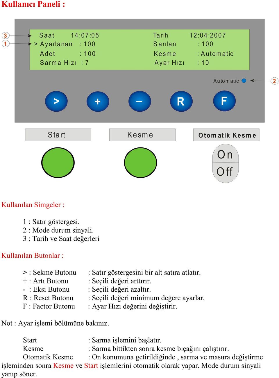
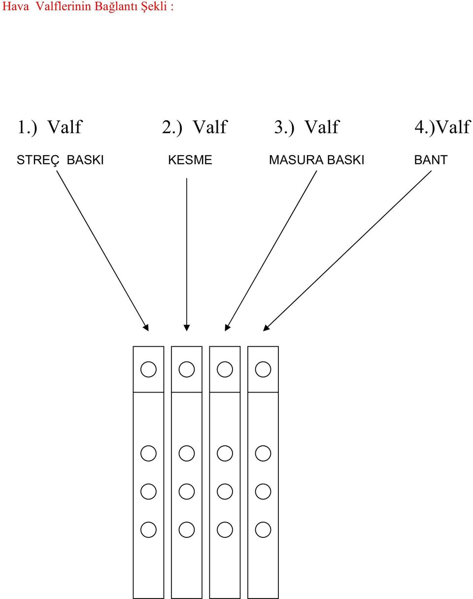
15 Makine Kontrol Sistem Blok Diyagram LCD Panel Kontrol Panel Kartý Buton Unitesi Ana Kart 5V DC Güç 24V DC Güç Hava Unitesi Pneumatic Valf Unitesi 3P Inverter Motor Encoder 3P Güç Pneumatic Piston

16

17 K1 Data Hatlarý Piston Led leri P1 - Bant Valf p2- Streç Baský Valf p3 - Masura Baský Valf p4 - Kesme Valf p5 - NC K1 Data Ledleri Jp1 CPU P1 p2 p3 p4 p5 g1 g2 g3 g4 g5 g6 g7 g8 g1 - Stop Buton g2 - Start Buton g3 - Kesme Anahtar g4 _ Kesme Seçim g5 - Kesme Buton g6 - Pedal g12 - Baský Buton g11 - Bant Buton (+) (-) Jp2 Power g9 g10 g11 g12 g10 g9 g8 g7-30a - K1 Beyaz Encoder RS-232 Main Board
 (-) Jp2 Power g9 g10 g11 g12 g10 g9 g8 g7-30a - K1 Beyaz Encoder RS-232 Main")
18 Filtre ünitesi Buzzer Pot1 Power Jumper Reset Jumper CPU Power Þarj ünitesi B1 b2 b3 b4 b5 b6 Pot2 Batarya LCD Soketi Buton Soketi RS-232 Ana Kart RS-232 Terminal Ekran Kartý

19 Specifications ( V class) Model SV004iC5-1 SV008iC5-1 SV015iC5-1 SV022iC5-1 Motor rating [HP] [kw] Output ratings Capacity[kVA] FLA[A] Voltage Single phase, 200 to 230V Frequency 0 to 400Hz Input ratings Voltage Single phase, 200 to 230V ( 10% ) Frequency 50 to 60Hz ( 5% ) Control Control method V/F control, Sensorless vector control Frequency setting resolution Digital reference : 0.01Hz Analog reference : 0.06Hz/60Hz Frequency setting accuracy Digital : 0.01% of Maximum output frequency Analog : 0.1% of Maximum output frequency V/F ratio Linear, Squar pattern, User V/F Overload capacity 1min. at 150%, 30sec. at 200% ( with inverse characteristic ) Torque boost Manual( 0 to 15% adjustable ), Auto Operation Input signal Operator control Keypad / Terminal / Communications Frequency setting Analog : 0~10V/4~20mA Digital : Keypad Communication : RS485 Start signal Forward / Reverse Multi-step Setting up to 8 speeds ( use multi-function terminal ) Multi-step accel 0.1~6000 sec. Max. 8 types available by multi-function terminal /decel time Selectable accel/decel patterns : Linear, U and S Emergency stop Interrupting the output of the drive Jog Jog operation Fault reset Reset the fault when protective function is active Output signal Operation status & Frequency detection, Overload alarm, Stalling, Overvoltage, Undervoltage, Fault output Drive overheating, Run, Stop, Constant speed, Speed searching, Fault output ( Relay and Open collector output ) Indicator Choose one from output frequency, current, voltage and DC voltage.(output voltage : 0~10V ) Operation DC braking, Frequency limit, Frequency jump, Second function, function Slip compensation, Reversing prevention, Auto restart, PID control Protection functions Drive trip Overvoltage, Undervoltage, Overcurrent, Drive overtemperature, Motor overtemperature, I/O phase loss, I/O mis-wiring, Overload, External device fault 1.2, Loss of speed command, Hardware fault, Communication error, CPU error Drive alarm Stall prevention, Overload alarm Momentary Less than 15 msec : keeping operation power less More than 15 msec : auto restart available Display keypad Operation information Trip information Output frequency, current and voltage, Set frequency value, Operation speed, DC voltage Display the trip cause when the protection function activates. Recent 5 faults records stored Environment Operating ambient temp. -10 ~ 40 Storage temperature -20 ~ 65 Humidity 90%Rh max.(non condensing) Altitude & Vibration 1000m max, 5.9m/sec 2 (0.6g) max. Atmosphere No corrosive gas, flammable gas, oil mist or dust Pressure 70~106k Pa 06

20 short-circuit link (* reserved for DC reactor) P P1 N MCCB AC input Single phase 200 ~ 230V L1 L2 U V IM G W Ground KNOB Multi-function input terminals, P1 to P5 P1 (factory set : Forward) Analog output (0~10V) P2 (factory set : Reverse) AM AM P3 (factory set : Emergency stop) Multi-function Input terminal P4 (factory set : Jog) CM P5 (factory set : Fault reset) P24 PNP DC24V output 30A 30B Multi-function relay output terminal 30C VR Power for speed signal (12V 10mA) VI Speed signal input (0~10V) MO EXTG Multi-function open collector output terminal I Speed signal input (4~20mA) CM Common Note : 1.= Main circuit terminal = Control circuit terminal 2. Analog output voltage is adjustable upto 12V. 3. Speed command can be set by Voltage, Current, Voltage+Current, Keypad, Keypad knob+voltage, and Keypad knob+current. 4. Brake unit and Brake resistor are optional. 07

21 Terminal L1, L2 P1, N Signal AC line input Braking unit Drive output DC reactor Ground U, V, W P, P1 G Input Terminal P1, P2 Signal Multi-function input 3 phase output terminals to motor Connecting DC reactor Chassis ground Description Used for multi-function input. Factory default settings are as follows. P1 = FX, Forward P3, P4, P5 P24 VR VI PNP DC24V output Frequency setting power Frequency setting(voltage) P2 = RX, Reverse P3 = BX, Emergency stop P4 = JOG P5 = RST, Fault reset DC24V power supply in case of PNP mode Power for Analog frequency setting, Maximum output is +12V 10mA Input DC 0 to 10V to set frequency. Input resistance is 20k CM AM-CM Common For monitoring Common terminal for the analog frequency setting signal and the FM(for monitoring) Output one out of Output frequency, Output current, Output voltage and DC voltage. I Output Description Single phase AC line input Connecting braking unit ( contact before ordering ) Frequency setting(current) 330A, 30C Multi-function relay and 30B Open collector output MO-EXTG Terminal Input DC 4 to 20mA to set frequency. Input resistance is 250 Factory default set is to Output frequency. Maximum output voltage = 0 to 12V, output current = 10mA To interrupt the output when the protection function activates or output multi-function signal. Multi-function relay terminal : Max. AC250V/1A, DC30V/1A Open collector output terminal : Max. DC24V 50mA Key RUN STOP/RESET Function Run key Stop/Reset key Program/Enter Frequency Selection Up KNOB(Volume) NPN/PNP Down Left Right 08 Description To operate the drive To stop operating or reset in case of fault To change parameters and save them To change the frequency Mode selection between NPN and PNP To increase the parameter values To decrease the parameter values To move the cursor left To move the cursor right
22 Parameter group There are 4 parameter groups to set parameters properly for the operation. Group Drive group Function 1 group Function 2 group Input/Output group Description Basic parameters such as Command frequency, Accel/Decel time, etc. Basic functional parameters such as Max. frequency, Torque boost, etc. Application parameters such as Frequency jump, Max./Min. of limit of frequency, etc. Parameters to construct the sequence such as Multi-function terminal setting, Auto operation, etc. Parameter group navigation DRV Gr. FU1 Gr. FU2 Gr. I/O Gr. Drive group Function 1 group Function 2 group Input/Output group Basic operation parameters such as Command frequency, Accel/Decel time, etc. Basic functional parameters for adjusting Output frequency, Voltage, etc. Application parameters of PID operation, The 2nd motor setting, etc. Parameters to construct the sequence such as Multi-function terminal setting, etc Shifting between groups is possible only in the first code of each group. Shift by using Right shift key () Shift by using Left shift key () (1) (1) (1) The value of the Command frequency will be displayed in the first code of the Drive group. It will show the value set by the operator. The factory set value is
23 Parameter navigation in Drive group The first code 0.0 displayed. Press up() key once to move to next code. The second code ACC appears. Press up() key once to move to next code. The third code dec is shown. Press up() key to move to next code. To move to the last code press up() key until drc appears. Press up() key once more to return to the first code. To move in reverse order use down() key. Procedure to set command frequency in Drive group To input new command frequency 30.05[Hz] from 0.0 set in the factory The first code 0.0 displayed. Press pro/ent() key. The digit of the first decimal place can be changed. Press right () key. The digit of the second decimal place can be changed. Press up() key until the digit becomes 5. Press left() key. The left digit can be set. Press left() key. Press left() key. Though 00.0 is displayed, the actual value remains at Make 3 by pressing up() key. Press pro/ent() key is flickering. Press pro/ent() key to stop the flickering. Command frequency 30.0 is stored. Note : (1) The LCD on the keypad of Drive ic5 displays only 3 digits. Use the shift keys ( ) to monitor and set the parameters. (2) To cancel the parameter setting press the shift keys ( or ) while 30.0 is flickering in the procedure no
24 Drive group FU1 group Keypad display Description Setting range Factory default 0.00 Output frequency : during run Reference frequency : during stop 0 to Max. frequency[hz] 0.00 Yes ACC Acceleration time 0 to 6000 [sec] 5 Yes DEC Deceleration time 0 to 6000 [sec] 5 Yes 0(Keypad) Drv Drive mode 1(Fx/Rx-1) 2(Fx/Rx-2) 1 No 3(ModBus) 0(Keypad-1) 1(Keypad-2) 2(Volume) 3(V1) Frq Frequency mode 4(I) 0 No 5(Volume+1) 6(V1+I) 7(Volume+V1) 8(ModBus) St1 Step frequency 1 0 to Max. frequency[hz] Yes St2 Step frequency 2 0 to Max. frequency[hz] Yes St3 Step frequency 3 0 to Max. frequency[hz] Yes Cur Output current *[A] * * RPM Motor speed *[rpm] * * DCL DC voltage *[V] * * v0l/p0r/t0r User display selection * * * n0n Fault display * * * drc Motor direction set F(Forward) R(Reverse) F Yes FU1 Function Group 1 selection * Yes FU2 Function Group 2 selection * Yes I/O I/O Group selection * Yes F0 Jump to desired code # 1 to 60 1 Yes 0(None) F3 Run prevention 1(Forward disable) 0 No 2(Reverse disable) F5 Acceleration pattern 0(Linear) 1(S-curve) 0 No F6 Deceleration pattern 0(Linear) 1(S-curve) 0 No 0(Decel) F7 Stop mode 1(Dc-brake) 0 No 2(Free-run) F8 DC injection braking frequency F23 to 60[Hz] 5 No F9 DC injection braking ON-delay 0 to 60 [sec] 0.1 No F10 DC injection braking voltage 0 to 200[%] 50 No F11 DC injection braking time 0 to 60 [sec] 1 No F12 Starting DC injection braking voltage 0 to 200[%] 50 No F13 Starting DC injection braking time 0 to 60 [sec] 0 No F14 Motor exciting time 0 to 60 [sec] 1 No F20 Jog frequency 0 to 400 [Hz] 10 No F21 Maximum frequency 40 to 400 [Hz] 60 No F22 Base frequency 30 to Max. frequency[hz] 60 No F23 Starting frequency 0 to 10 [Hz] 0.1 No F24 Frequency limit selection 0(No), 1(Yes) 0 No F25 Frequency limit - high 0 to High limit [Hz] 60 No F26 Frequency limit - low Low limit to Max. frequency[hz] 0.5 No F27 Manual/Auto torque boost selection 0(Manual), 1(Auto) 0 No F28 Torque boost in forward direction 0.0 to 15.0[%] 5 No F29 Torque boost in reverse direction 0.0 to 15.0[%] 5 No 0(Linear) F30 Volts/Hz pattern 1(Square) 0 No 2(User V/F) 11 Adjustable during run
25 FU1 group FU2 group Keypad display Description Setting range Factory default F31 User V/F - frequency 1 0 to F33[Hz] 15 No F32 User V/F - voltage 1 0 to 100[%] 25 No F33 User V/F - frequency 2 F31 to F35[Hz] 30 No F34 User V/F - voltage 2 0 to 100[%] 50 No F35 User V/F - frequency 3 F33 to F37[Hz] 45 No F36 User V/F - voltage 3 0 to 100[%] 75 No F37 User V/F - frequency 4 F35 to Maximum frequency[hz] 60 No F38 User V/F - voltage 4 0 to 100[%] 100 No F39 Output voltage adjustment 40.0 to 110.0[%] 100 No F40 Energy save 0 to 30[%] 0 Yes F50 Electronic thermal selection 0(No), 1(Yes) 0 Yes F51 Electronic thermal level -1 min. F52 to 200[%] 150 Yes F52 Electronic thermal level -continuous 50 to F51[%] 100 Yes F53 Motor cooling system 0(self cool) 1(forced cool) 0 Yes F54 Overload alarm level 30 to 150[%] 150 Yes F55 Overload alarm hold time 0 to 30[sec] 10 Yes F56 Overload trip selection 0(No), 1(Yes) 1 Yes F57 Overload trip level 30 to 200[%] 180 Yes F58 Overload trip delay time 0 to 60[sec] 60 Yes 000 to 111(bit set) F59 Stall prevention mode selection Bit 0 : During accel. Bit 1 : During steady speed 000 No Bit 2 : During decel. F60 Stall prevention level 30 to 150[%] 150 No H1 Previous fault history 1 non * H2 Previous fault history 2 non * H3 Previous fault history 3 non * H4 Previous fault history 4 non * H5 Previous fault history 5 non * H6 Delete fault history 0(No), 1(Yes) 0 Yes H7 Dwell frequency 0 to Max. frequency[hz] 5 No H8 Dwell time 0 to 10[sec] 0 No H10 Selection of jump frequency 0(No), 1(Yes) 0 No H11 Jump frequency 1, low 0 to H12[Hz] 10 No H12 Jump frequency 1, high H11 to Maximum frequency[hz] 15 No H13 Jump frequency 2, low 0 to H14[Hz] 20 No H14 Jump frequency 2, high H13 to Maximum frequency[hz] 25 No H15 Jump frequency 3, low 0 to H16[Hz] 30 No H16 Jump frequency 3, high H15 to Maximum frequency[hz] 35 No H17 Inclination at the beginning of S curve 1 to 100[%] 40 No H18 Inclination at the end of S curve 1 to 100[%] 40 No H19 Output phase loss protection 0(No), 1(Yes) 0 Yes H20 Power ON start selection 0(No), 1(Yes) 0 Yes H21 Restart after fault reset 0(No), 1(Yes) 0 Yes 0000 to 1111(bit set) Bit 0 : During accel. H22 Speed search selection Bit 1 : After fault reset 0 No Bit 2 : Restarted after instant power failure Bit 3 : When H20 is set to 1(Yes) H23 Speed search current limitation level 8 to 200[%] 100 Yes H24 Speed search P gain 0 to Yes H25 Speed search I gain 0 to Yes H26 Number of auto restart attempt 0 to 10 0 Yes H27 Delay time before auto restart 0 to 60[sec] 1 Yes H30 Motor power rating selection 0.2, 0.75, 1.5, 2.2[kW] * No H31 Number of motor poles 2 to 12 4 No H32 Rated motor slip 0 to 10[Hz] * No H33 Rated motor current in RMS 0 to 20[A] * No H34 No load motor current in RMS 0.1 to 20[A] * No H36 Motor efficiency 70 to 100[%] * No 12 Adjustable during run
26 FU2 group Keypad display Description Setting range Factory default H37 Load inertia 0 to 2 0 No H39 Carrier frequency 1 to 15[kHz] 3.0 Yes 0(V/F) H40 Control mode selection 1(Slip compen) 2(PID) 0 No 3(Sensorless vector control) H41 Auto tuning 0 to 1 0 Yes H42 Stator reristance 0 to 5 [ߟ] 0 Yes H44 Leakage inductance 0 to 300[mH] 0 Yes H45 Sensorless P gain 0 to Yes H46 Sensorless I gain 0 to Yes H50 PIP feedback signal selection 0(I) 1(V1) 0 No H51 P gain for PID control 0 to 999.9[%] 300 Yes H52 I gain for PID control 0.1 to 32.0[sec] 1 Yes H53 D gain for PID control 0.1 to 30.0[sec] 0 Yes H54 F gain for PID control 0 to 999.9[%] 0 Yes H55 Limit frequency for PID control 0 to Max. frequency[hz] 60 Yes H70 Reference frequency for Accel/Decel 0(Max. freq.) 1(Delta freq.) 0 Yes 0(0.001sec) H71 Accel/Decel time scale 1(0.01sec) 1 No H72 Power On display 2(1sec) 0(Command frequency) 1(Accel. Time) 2(Decel. Time) 3(Drive mode) 4(Frequency mode) 5(Step frequency 1) 6(Step frequency 2) 7(Step frequency 3) 0 Yes 8(Current) 9(Speed) 10(DC link voltage) 11(User display) 12(Fault display) 13(Motor direction) 0(Voltage) H73 User display selection 1(Watt) 0 Yes 2(Torque) H74 Gain for motor speed display 1 to 1000[%] 100 Yes H79 Software version x.xx x.xx * H81 2nd acceleration time 0 to 6000 [sec] 5 Yes H82 2nd deceleration time 0 to 6000 [sec] 10 Yes H83 2nd acceleration time 30 to Max. frequency[hz] 60 No 0(Linear) H84 2nd V/F pattern 1(Square) 0 No 2(User V/F) H85 2nd forward torque boost 0.0 to 15.0[%] 5 No H86 2nd reverse torque boost 0.0 to 15.0[%] 5 No H87 2nd stall prevention level 30 to 150[%] 150 No H88 2nd electronic thermal level -1 min. H89 to 200[%] 150 Yes H89 2nd electronic thermal level -continuous 50 to H88[%] 100 Yes H90 2nd motor rated current 0.1 to 20[A] * No 0(No) 1(All groups) H93 Parameter initializing 2(Drive) 3(Function 1) 0 No 4(Function 2) 5(I/O) H94 Parameter writing protection 0 to FFF 0 Yes H95 Parameter change protection 0 to FFF 0 Yes 13 Adjustable during run
27 I/O group Keypad display Description Setting range Factory default I1 Filtering time constant for V0 signal input 0 to 9,999[msec] 10 Yes I2 V0 input minimum voltage 0 to 10V 0 Yes I3 Frequency corresponding to I2 0 to 400 [Hz] 0.0 Yes I4 V0 input maximum voltage 0 to 10V 10 Yes I5 Frequency corresponding to I4 0 to 400 [Hz] 60.0 Yes I6 Filtering time constant for V1 signal input 0 to 9,999[msec] 10 Yes I7 V1 input minimum voltage 0 to 10V 0 Yes I8 Frequency corresponding to I7 0 to Max. frequency[hz] 0.0 Yes I9 V1 input maximum voltage 0 to 10V 10 Yes I10 Frequency corresponding to I9 0 to Max. frequency[hz] 60.0 Yes I11 Filtering time constant for I signal input 0 to 9,999[msec] 100 Yes I12 I input minimum current 0 to 20[mA] 4 Yes I13 Frequency corresponding to I12 0 to Max. frequency[hz] 0 Yes I14 I input maximum current I12 to 20[mA] 20 Yes I15 Frequency corresponding to I14 0 to Max. frequency[hz] 60.0 Yes 0(None) I16 Criteria for analog speed signal loss 1(Half of x1) 0 Yes 2(Below x1) 0(FX) 1(RX) 2(BX) 3(RST) 4(JOG) 5(Speed-L) 6(Speed-M) 7(Speed-H) 8(XCEL-L) Definition of multifunction 9(XCEL-M) I20 input terminal 10(XCEL-H) P18, 9, 15, 20, 21, 22, 23, 24, 25, 26 11(DC-Brake) 0 Yes ( - reserved - ) 12(2nd function) 15(Up) 16(Down) 17(3 wire) 18(EXT-A) 19(EXT-B) 21(Open-loop) 22(Main drive) 23(Analog hold) 24(XCEL-stop) I21 Definition of multifunction input terminal P2 Same as above I20 1 Yes I22 Definition of multifunction input terminal P3 Same as above I20 2 Yes I23 Definition of multifunction input terminal P4 Same as above I20 1 Yes I24 Definition of multifunction input terminal P5 Same as above I20 2 Yes I25 Terminal input status [bit] * * I26 Terminal output status 00-11[bit] * * I27 Filtering time constant for multifunction input terminal 0 to Max. frequency[hz] 15 Yes I30 Step frequency 4 0 to Max. frequency[hz] 30 Yes I31 Step frequency 5 0 to Max. frequency[hz] 25 Yes I32 Step frequency 6 0 to Max. frequency[hz] 20 Yes I33 Step frequency 7 0 to Max. frequency[hz] 15 Yes I34 Acceleration time 1 0 to 600 [sec] 3 Yes I35 Deceleration time 1 0 to 600 [sec] 3 Yes I36 Acceleration time 2 0 to 600 [sec] 4 Yes I37 Deceleration time 2 0 to 600 [sec] 4 Yes I38 Acceleration time 3 0 to 600 [sec] 5 Yes I39 Deceleration time 3 0 to 600 [sec] 5 Yes I40 Acceleration time 4 0 to 600 [sec] 6 Yes I41 Deceleration time 4 0 to 600 [sec] 6 Yes I42 Acceleration time 5 0 to 600 [sec] 7 Yes I43 Deceleration time 5 0 to 600 [sec] 7 Yes 14 Adjustable during run
28 FU2 group Keypad display Description Setting range Factory default I44 Acceleration time 6 0 to 600 [sec] 8 Yes I45 Deceleration time 6 0 to 600 [sec] 8 Yes I46 Acceleration time 7 0 to 600 [sec] 9 Yes I47 Deceleration time 7 0 to 600 [sec] 9 Yes 0(Frequency) I50 AM output 1(Current) 2(Voltage) 0 Yes 3(DC link voltage) I51 AM output adjustment 100 to 200[%] 100 Yes I52 Frequency detection level 0 to Max. frequency[hz] 30 Yes I53 Frequency detection bandwidth 0 to Max. frequency[hz] 10 Yes 0(FDT-1) 1(FDT-2) 2(FDT-3) 3(FDT-4) 4(FDT-5) 5(OL) 6(IOL) 7(Stall) I54 Definition of multifunction 8(OV) output terminal MO 9(LV) 12 Yes 10(OH) 11(Lost command) 12(Run) 13(Stop) 14(Steady) 15(Search) 16(Ready) 17(Fault select) I55 Definition of relay functions Same as above I54 12 Yes 000 to 111(bit set) I56 Fault relay setting Bit 0 : Low voltage (30A, 30B, 30C) Bit 1 : Trip 010 Yes Bit 2 : Number of auto retry I60 Inverter number 1 to 32 1 Yes 0(1200bps) 1(2400bps) I61 Baud rate 2(4800bps) 3 Yes 3(9600bps) 4(19200bps) 0(None) I62 Operating selection at loss of freq. reference 1(Free run) 3 Yes 2(Stop) I63 Waiting time after loss of freq. reference 0.1 to 12[sec] 10 Yes Adjustable during run 15
29 If protection function activates due to error/fault in the inverter, corresponding alarm is displayed on the keypad as shown below. Correct the error/fault before restarting or it may decrease the inverter s life expectancy. Display Fault/Error Overcurrent Ground fault Inverter overload Overload trip Coolingpin overheat DC link condenser overload Output phase loss Overvoltage Undervoltage Electronic thermal Parameter store error Hardware error Communication error Coolingfan error Output instant interrupting A contact fault signal input B contact fault signal input Frequency command loss Description Output current has been greater than 200% of the rated current. The inverter output is interrupted. Ground fault has been occurred at the load side of the inverter. The inverter output is interrupted. Output current greater than 150% of the rated current has been flowed over 1 min. The inverter output is interrupted. Output current has been greater than the set value (F57) of the rated current. The inverter output is interrupted. Cooling pin has been overheated due to high ambient temperature. The inverter output is interrupted. If the DC condenser of Inverter is in need of replacement the inverter output is interrupted. One or more of output line U, V and W lost. The inverter output is interrupted. The inverter main voltage has been risen above the permissible limit 400V. Check if deceleration time has been set too short or line input voltage is too high. The inverter output is interrupted. The inverter output is interrupted according to the set time-inverse curve to prevent the overtemperature of the motor due to overloads. Error has been occurred on the storing of the changed parameters. It is displayed when power is on. It is displayed in case of software error. It is not possible to reset by STOP/RST key on the keypad or reset terminals. Open the inverter power and make sure the keypad power is off and close the power again. Communication error between controller and keypad. It is not possible to reset by STOP/RST key on the keypad or reset terminals. Open the inverter power and make sure the keypad power is off and close the power again. Error has been occurred on the coolingfan. The inverter output is interrupted in the case that BX terminal is ON. Warning : To restart the drive make BX terminal OFF during the FX /RX is ON. If I20/21/22/23/24 set to 18 is ON, the inverter output is interrupted. If I20/21/22/23/24 set to 19 is ON, the inverter output is interrupted. If signal input is failed for the driving by using analog input or option(rs485), try to drive according to the setting at I62. 16
30 Fault/Error Possibsle cause Solution Overcurrent Ground fault Accel/Decel time is not enough for the load inertia (GD 2 ) Increase the Accel/Decel time The load is greater than the rating of the inverter. Inverter output is assigned during the free run of the motor. The motor brake operates too fast. Ground fault at the load side of the inverter. Insulation of the motor is broken. Replace the inverter with a higher rating Operate after the motor stops or use speed search(h22) in FU2 in the output terminals. Verify the output wiring Verify the mechanical brake. Check to see if there is something wrong with output wiring. Replace a motor. Inverter overload Overload trip Cooling fan overheat The load is greater than the rating of the inverter. Increase the ratings of a motor and an inverter. Power rating is set to the lower value than the load Check to see if the setting is correct. Torque boost is too great. Reduce the torque boost. Check to see if there is any alien substance in the ventilation Fault in the cooling system. system. The cooling fan is used beyond the life expectancy. Replace the cooling fan. High ambient temperature Keep the ambient temperature below 40. Output phase loss Coolingfan error Overvoltage Undervoltage Electronic thermal Fault in the load side contactor Wiring problem Alien substances are in the ventilator. The cooling fan is used beyond the expectancy. Decel time is not enough for the load inertia(gd 2 ) There is a survived load in the load side. Higher voltage than rating is supplied. Lower voltage than rating is supplied. Power capacity is not enough for the additional loads like welders and direct-on-line starting motors. Fault in the line side contactor Overtemperature of the motor The load is greater than the rating of the inverter. Electronic thermal level is set lower than rating. Inverter power rating is set to the lower value than the load Long operation at low speed. Replace the contactor. Verify the output wiring Check to see if there is any alien substance in the ventilation system. Replace the cooling fan. Increase the Decel time Uase DB unit. Verify the power voltage. Verify the power voltage. Increase the power capacity. Replace the contactor. Reduce the load or operation times. Increase the ratings of the inverter. Adjust the electronic thermal properly. Adjust the inverter rating properly. Replace the motor with the separated power cable for the cooling fan. A contact fault signal input B contact fault signal input The terminal I20/21/22/23/24 set to18/19 is ON Verify the circuits connected to the external fault terminals. Frequency command loss Frequency command loss at terminals V1 and I Verify the wiring connected to V1 and I terminals. Parameter store error Output instant interrupting Refer to LG or distributors Communication error 17
Starvert ic5. Variable Frequency Drive / Inverter. Automation Equipment. Leader in Electrics & Automation
 Leader in Electrics & Automation Variable Frequency Drive / Inverter Starvert ic5 0.4-2.2kW 1 phase 200-230Volts 0.4-0.75kW 3 phase 200-230Volts Automation Equipment Global standard ic5, serves a wide
SAFETY INSTRUCTIONS WARNING
 Important User Information Thank you for purchasing LS Variable Frequency Drives! SAFETY INSTRUCTIONS Always follow safety instructions to prevent accidents and potential hazards from occurring. In this
SAFETY INSTRUCTIONS WARNING
 Thank you for purchasing LG Variable Frequency Drives! SAFETY INSTRUCTIONS Always follow safety instructions to prevent accidents and potential hazards from occurring. In this manual, safety messages are
www.lsis.com Variable Frequency Drive ic5 0.4~2.2kW (0.5~3HP) 1 Phase 200-230Volts
 1 Phase 200-230Volts") www.lsis.com Variable Frequency Drive ic5 0.4~2.2kW (0.5~3HP) 1 Phase 200-230Volts Global standard ic5, serves a wide variety of applications to meet the majority of user needs. Modbus communication (Option)
www.lsis.com Variable Frequency Drive ic5 0.4~2.2kW (0.5~3HP) 1 Phase 200-230Volts Global standard ic5, serves a wide variety of applications to meet the majority of user needs. Modbus communication (Option)
SAFETY INSTRUCTIONS. Always follow safety instructions to prevent accidents and potential hazards from occurring.
 Thank you for purchasing LS Variable Frequency Drives! SAFETY INSTRUCTIONS Always follow safety instructions to prevent accidents and potential hazards from occurring. In this manual, safety messages are
STARVERT ig5a. Compact & Powerful Inverter. 0.4~7.5kW 3Phase 200~230Volts 0.4~7.5kW 3Phase 380~480Volts. Automation Equipment
 Leader in Electrics & Automation STARVERT iga Compact & Powerful Inverter.4~7.kW 3Phase 2~23Volts.4~7.kW 3Phase 38~48Volts Automation Equipment Inverter STARVERT iga LS Starvert iga is very competitive
SAFETY INSTRUCTIONS. Always follow safety instructions to prevent accidents and potential hazards from occurring.
 Thank you for purchasing LS Variable Frequency Drives! SAFETY INSTRUCTIONS Always follow safety instructions to prevent accidents and potential hazards from occurring. In this manual, safety messages are
SJ200 Series Inverter Quick Reference Guide
 SJ2 Series Inverter Quick Reference Guide Single-phase Input 2V Class Three-phase Input 2V Class Three-phase Input 4V Class Hitachi Industrial Equipment Systems Co., Ltd. Manual No. NB6501XA March 24 Caution:
SAFETY INSTRUCTIONS. To prevent injury and property damage, follow these instructions during the installation and operation of the inverter.
 Thank you for purchasing LS Variable Frequency Drives! SAFETY INSTRUCTIONS To prevent injury and property damage, follow these instructions during the installation and operation of the inverter. Incorrect
SINUS M. USER MANUAL -Installation and Programming Instructions-
 15P0073B1 SINUS M VARIABLE FREQUENCY DRIVE USER MANUAL -Installation and Programming Instructions- Issued on 17/02/11 R.03.1 SW Ver. EU2.3 English This manual is integrant and essential to the product.
User Manual. MODBUS-RTU Option Board for SV-iS5 Series. LG Industrial Systems
 User Manual MODBUS-RTU Option Board for SV-iS5 Series Read this manual carefully before using the MODBUS-RTU Option board and follow the instructions exactly. After reading this manual, keep it at handy
User manual. MODBUS-RTU SV-iC5. LG Industrial Systems
 User manual MODBUS-RTU SV-iC5 Read this manual carefully before installing, wiring, operating, servicing or inspecting the drive. Keep this manual within easy reach for quick reference. LG Industrial Systems
A1000 Cheat Sheet (Open Loop Vector)
") A1000 Cheat Sheet (Open Loop Vector) The following procedure is a supplement to supplied with this equipment and will guide the user in properly wiring the A1000 and. It will also show the user how to
A1000 Cheat Sheet (Open Loop Vector) The following procedure is a supplement to supplied with this equipment and will guide the user in properly wiring the A1000 and. It will also show the user how to
NX Series Inverters. HVAC Pocket Programming Guide
 NX Series Inverters HVAC Pocket Programming Guide HVAC Pocket Programming Guide HVAC Pocket Programming Guide / Contents This guide provides a single reference document for the user of NXL HVAC (product
J1000. System configuration
 YASKAWA JZ J1000 The basic inverter V/f controlled inverter Good torque performance (150% / 3 Hz) Double rating ND 120%/1min and HD 150%/1 min Overload detection function (150% during 60s) thermal function
TABLE OF CONTENTS. Fig. 1 EV Pictorial Wiring Diagram 5. Section 2 Inverter Option Modules 6
 TABLE OF CONTENTS Introduction.. 3 Section 1 Safety Precautions.. 3 1.1 Preface.. 3 1.2 Receiving and Inspection... 3 1.3 Installation and Pre-operation 4 1.4 During Power ON. 4 Fig. 1 EV Pictorial Wiring
MC Series Drives. Flexible, simple, rugged, robust! Phone: 800.894.0412 - Fax: 888.723.4773 - Web: www.actechdrives.com - Email: info@actechdrives.
 Drives Flexible, simple, rugged, robust! Our promise Commitment to Price Leadership Price leadership is serious business. It takes continuous life cycle management to make price leadership a sustainable
VS-606V7 Series Instruction Manual COMPACT GENERAL-PURPOSE INVERTER (VOLTAGE VECTOR CONTROL)
") VS-606V7 Series Instruction Manual COMPACT GENERAL-PURPOSE INVERTER (VOLTAGE VECTOR CONTROL) PREFACE YASKAWA s VS-606V7 is such a small and simple inverter; as easy as using a contactor. This instruction
VS-606V7 Series Instruction Manual COMPACT GENERAL-PURPOSE INVERTER (VOLTAGE VECTOR CONTROL) PREFACE YASKAWA s VS-606V7 is such a small and simple inverter; as easy as using a contactor. This instruction
32VFD Variable Frequency Drives for Centrifugal Chillers
 32VFD 32VFD Variable Frequency Drives for Centrifugal Chillers ENERGY-SAVING CONTROL FOR CENTRIFUGAL CHILLERS Reduce energy consumption in your existing centrifugal chiller Your chiller was specified to
SAFETY INSTRUCTIONS. Always follow safety instructions to prevent accidents and potential hazards from occurring.
 Thank you for purchasing LS Variable Frequency Drive! SAFETY INSTRUCTIS Always follow safety instructions to prevent accidents and potential hazards from occurring. In this manual, safety messages are
APPENDIX. SureSERVO QUICK START GUIDE. In This Appendix... Quick Start for SureServo Drives...A 2. Tuning Quick Start for SureServo Drives...
 SureSERVO QUICK START GUIDE APPENDIX BA In This Appendix... Quick Start for SureServo Drives.............A 2 Spin the Motor......................................A 2 Position Mode Quick Start (Pt & Pr)......................A
2011 Industrial Catalog. DRIVES, PAC, PLCs. Industrial Catalog 2011. www.toshiba.com/ind
 www.toshiba.com/ind 2011 Toshiba International Corporation Rev. 110504 Industrial Catalog 2011 13131 W. Little York Road Houston, TX 77041 Tel: 713-466-0277 Fax: 713-466-8773 US: 800-231-1412 Canada: 800-872-2792
GPD 506/P5 Start-up Procedure and Checklist
 GPD 506/P5 Start-up Procedure and Checklist Preparation for GPD506/P5 Drive Start-Up...2 HVAC Start-Up Procedure for GPD 506/P5 WITH Bypass Option:...4 HVAC Start-Up Procedure for GPD 506/P5 WITHOUT Bypass
Emotron VSA Variable Speed Drive
 Emotron VSA Variable Speed Drive Instruction manual English Quick Start Guide This guide is designed to assist in installing and running the variable speed drive to verify that the drive and motor are
HF430 AC Drive Pocket Guide
 HF430 AC Drive Pocket Guide Safety Refer to the Safety section in the HF430 drive instruction manual for full details. As a minimum, observe the following. DANGER DANGER HAZARD OF ELECTRICAL SHOCK OR BURN.
WJ200 series Pursuing the Ideal Compact Inverter
 WJ200 series Pursuing the Ideal Compact Inverter X200 series Simple, Trip-suppression and Eco-friendly Compact Inverter NE-S1 series Economical Inverter with Simple Operation L700 series Inverter designed
AC ADJUSTABLE SPEED DRIVES MICRO SERIES INVERTERS
 MICRO SERIES INVERTERS MICRO SERIES INVERTER DRIVES Full feature, ultra-friendly operation. Programs and reads-out in plain English. Intelligent Power Module-IGBT s with a 16 bit Intel microprocessor.
Number 1 in efficiency
 PowerXL DE1 Variable Speed Starter www.eaton.eu/de1 Number 1 in efficiency The easiest way of variable motor speed NEW Variation DE11 The new device category! The PowerXL DE1 Variable Speed Starter Why
Apéndice E Listado de constantes
 Listado de constantes Operation U1 Monitor U1--01 Frequency Ref Hz -- -- Q Q Q Q U1--02 Output freq Hz -- -- Q Q Q Q U1--03 Output current A -- -- Q Q Q Q U1--04 Control Method -- -- -- Q Q Q Q U1--05
Easy to connect - Easy to configure Easy to install
 SIMPLE TO USE... CG Drive- SK is an easy drive - easy to connect, easy to configure and easy to install. Easy to connect - All connectors are generously sized and clearly labeled. Easy to configure - The
Content. Operational manual for RBU
 Content Operational manual for RBU 1 Safety Precautions...1 1.1 Safety definition... 1 1.2 Warning symbols... 1 1.3 Safety guidelines... 1 2 Inspection...4 2.1 Unpacking inspection... 4 2.2 Application
Frequency Converter Fv
 2 Bosch Rexroth AG Electric Drives and Controls Documentation Brake chopper with up to 30 kw continuous braking power Easy to operate and service (detachable fan, LCD operating panel with copy function)
ACS800. Firmware Manual ACS800 Standard Control Program 7.x
 ACS800 Firmware Manual ACS800 Standard Control Program 7.x ACS800 Standard Control Program 7.x Firmware Manual 3AFE64527592 REV I EN EFFECTIVE: 18.05.2007 2007 ABB Oy. All Rights Reserved. 5 Table of
How To Use The Vacon 0 Machinery
 vacon 0 machinery how would you like your ac drive today? easy adaptation for customer requirements The Vacon 0 Machinery is an extremely compact AC drive for machine builders in the power range from 0.25
YASKAWA AC Drive A1000
 YASKAWA AC Drive A1000 Crane Software Application Manual Software No. VSA90507X Type: CIMR-AC Models: 200 V Class: 0.4 to 110 kw (1.2 to 160 kva) 400 V Class: 0.4 to 300 kw (1.4 to 460 kva) To properly
HITACHI INVERTER SJ/L100/300 SERIES PID CONTROL USERS GUIDE
 HITACHI INVERTER SJ/L1/3 SERIES PID CONTROL USERS GUIDE After reading this manual, keep it for future reference Hitachi America, Ltd. HAL1PID CONTENTS 1. OVERVIEW 3 2. PID CONTROL ON SJ1/L1 INVERTERS 3
MEMOBUS/Modbus Communications
 2 2.1 MEMOBUS/MODBUS CONFIGURATION............260 2.2 COMMUNICATION SPECIFICATIONS..............261 2.3 COMMUNICATION TERMINAL RESISTANCE........262 2.4 CONNECTING A PLC...........................263 2.5
FlexPak 3000 Digital DC Drive Software Reference Manual Version 4.3
 FlexPak 3000 Digital DC Drive Software Reference Manual Version 4.3 Instruction Manual D2-3405-2 The information in this manual is subject to change without notice. Throughout this manual, the following
Bulletin 150 SMC Flex Smart Motor Controller Specifications
 Specifications Specifications Standard Features Optional Features Installation Setup Communications Power Wiring Control Wiring Keypad Software Starting and Stopping Modes Protection and Diagnostics Metering
1000 Hz High Frequency Custom Software
 YASKAWA AC Drive - V1000 Option 1000 Hz High Custom Software Supplement Software No. VSV91005X To properly use the product, read this manual thoroughly and retain for easy reference, inspection, and maintenance.
LIFT CONTROL SYSTEMS CATALOGUE 2007
 LIFT CONTROL SYSTEMS CATALOGUE 2007 All Your Needs For Elevators INDEX 1. Lift Control Cards... 3 2. Speed Control Units... 7 3. Emergency Rescue Cards... 8 4. Lift Control Panels... 10 5. Photocells...
LIFT CONTROL SYSTEMS CATALOGUE 2007
 LIFT CONTROL SYSTEMS CATALOGUE 2007 All Your Needs For Elevators INDEX 1. Lift Control Cards... 3 2. Speed Control Units... 7 3. Emergency Rescue Cards... 8 4. Lift Control Panels... 10 5. Photocells...
EFC 3600. Frequency converters
 2 Bosch Rexroth AG Electric Drives and Controls Documentation Compact and complete: space saving side-by-side assembly, plug-in I/O terminals, with brake chopper and mains filter for ultra-simple installation
Remove the terminal cover to expose the motor and power terminals.
 Quick Start Guide This guide is to assist in installing and running the inverter to verify that the drive and motor are working properly. Starting, stopping and speed control will be from the keypad. If
Display Group Parameters
 1 Display Group Parameters No. Parameter Min/Max Display/Options d1 [Output Freq]./[Maximum Freq].1 Hz d2 [Commanded Freq]./[Maximum Freq].1 Hz d3 [Output Current]./Drive Amps 2.1 Amps d4 [Output Voltage]
LG Air Conditioning Multi F(DX) Fault Codes Sheet. Multi Split Units
 Fault Codes Sheet. Multi Split Units") Multi Split Units If there is a fault on any LG Multi unit, an Error mark is indicated on the display window of the indoor unit, wired-remote controller, and LED s of outdoor unit control board. A two
Multi Split Units If there is a fault on any LG Multi unit, an Error mark is indicated on the display window of the indoor unit, wired-remote controller, and LED s of outdoor unit control board. A two
VCM Installation and Operations Manual. Table of Contents
 Table of Contents VCM Installation and Operations Manual 1.0 Introduction... 1 2.0 Product Inspection... 2 2.1 Nameplate Layout... 2 3.0 Operating Precautions... 3 3.1 Before Power up... 3 3.2 During Power
ACS800. Firmware Manual ACS800 Standard Control Program 7.x
 ACS800 Firmware Manual ACS800 Standard Control Program 7.x ACS800 Standard Control Program 7.x Firmware Manual 3AFE64527592 REV L EN EFFECTIVE: 2011-08-25 2011 ABB Oy. All Rights Reserved. 5 Table of
ABB general machinery drives. User s manual ACS355 drives
 ABB general machinery drives User s manual ACS355 drives List of related manuals Drive manuals and guides Code (English) ACS355 user s manual 3AUA0000066143 1) ACS355 drives with IP66/67 / UL Type 4x enclosure
VARIABLE SPEED DRIVE UNIT INVERTER. VAT20 1ph 200V-240V system, 0.2-0.75kW 1ph/3ph 200/240V system, 1.5-2.2kW. 3ph 380/460V system, 0.75-2.
 GE Power Controls VARIABLE SPEED DRIVE UNIT INVERTER VAT20 1ph 200V-240V system, 0.2-0.75kW 1ph/3ph 200/240V system, 1.5-2.2kW 3ph 380/460V system, 0.75-2.2kW INSTRUCTION MANUAL ------------------------------------------------------------
ABB machinery drives. User s manual ACS355 drives
 ABB machinery drives User s manual ACS355 drives List of related manuals Drive manuals and guides ACS355 user s manual ACS355 drives with IP66/67 / UL Type 4x enclosure supplement ACS355 quick installation
VFD-M Series Mini Type Sensor-less Vector Frequency Inverter
 VFD-M Series Mini Type Sensor-less Vector Frequency Inverter Operation Manual Material Version:V1.1 Date of Filing:2013-01-24 Company Standard: Q/0300SSC 001-2012 SPECTRA Technology CO., LTD. could supply
Manual No. YEG-TOE-S616-55.1-OY. VARISPEED F7 Vector Control Frequency Inverter USER S MANUAL
 Manual No. YEG-TOE-S616-55.1-OY VARISPEED F7 Control Frequency Inverter USER S MANUAL Table of Content Warnings... VII Safety Precautions and Instructions for Use... VIII EMC Compatibility... X Line Filters...
VARISPEED V7 IP65 Compact Sensorless Vector Inverter USER S MANUAL
 V7_IP65.qxd 15.02.2006 13:17 Uhr Seite 1 Manual No. I161E-EN-01 VARISPEED V7 IP65 Compact Sensorless Vector Inverter USER S MANUAL OMRON YASKAWA MOTION CONTROL B.V. Wegalaan 65 2132 JD Hoofddorp The Netherlands
The HVAC SOLUTION DELIVERING POWER...SAVING ENERGY
 The HVAC SOLUTION DELIVERING POWER...SAVING ENERGY PowerGate - Cost effective solutions for F 1 Horsepower Rating 001 1-40 HP (208V) 075 1-75 HP (480V) Input Voltage 2V 208-240V 4V 380-480V Disconnect
Harmonic Drive acutator P r e c i s i o n G e a r i n g & M o t i o n C o n t r o l
 D C S e r v o S y s t e m s RH Mini Series Total Motion Control Harmonic Drive acutator P r e c i s i o n G e a r i n g & M o t i o n C o n t r o l Precision Gearing & Motion Control DC SERVO ACTUATORS
Siemens Standard Drives. Application Handbook
 Siemens Standard Drives Application Handbook Martin Brown Siemens Standard Drives Congleton December 1997 1. Introduction....4 1.1 What is a Variable Speed Drive?...4 1.2 The Variable Frequency Inverter...7
Configuring Allen-Brandly ControlLogix PLC with Moxa MGate 5105-MB-EIP. 1 Application Description... 3. 1.1 Objective... 3 1.2 Goals...
 Moxa MGate 5105-MB-EIP Contents Moxa Technical Support Team support@moxa.com 1 Application Description... 3 1.1 Objective... 3 1.2 Goals... 3 2 System Topology... 3 3 Hardware and Software Requirements...
SUBJECT: How to wire a motor starter Number: AN-MC-004 Date Issued: 2/08/2005 Revision: Original
 SUBJECT: How to wire a motor starter Number: AN-MC-004 Date Issued: 2/08/2005 Revision: Original A motor starter is a combination of devices to allow an induction motor to start, run and stop according
... Electronic Softstarter...
 . CT-START Electronic Softstarter. 6 A. to 900. A......... CT START CT-START is a multi-function electronic system with a microcontroller and thyristors, designed for use with all 3-phase squirrel cage
STARTING GUIDE FRENIC-Eco. FRN-F1. Frequency inverter for HVAC applications. 3-phase 400V 0.75 560kW. Last update: 281020087 SG_Eco_EN_2.1.
 STARTING GUIDE FRENIC-Eco. FRN-F1 Frequency inverter for HVAC applications 3-phase 4V.75 56kW Last update: 281287 SG_Eco_EN_2.1. Version Changes applied Date Written Checked Approved 2.. Second edition
1 Application Description... 3. 1.1 Objective... 3 1.2 Goals... 3
 Contents Moxa Technical Support Team support@moxa.com 1 Application Description... 3 1.1 Objective... 3 1.2 Goals... 3 2 System Topology... 3 3 Hardware and Software Requirements... 4 4 Configuration...
Specifying a Variable Frequency Drive s
 Specifying a Variable Frequency Drive s Put on by Bruce Reeves and Jeremy Gonzales Dykman Electrical Covering the Western US For all of your VFD and Soft Start and Motor Needs How To Specify a Variable
August 2004. www.danahermotion.com SECO DC DRIVES. Table of Contents
 SECO DC DRIVES SECO AC/DC DC Drives DRIVES Table of Contents August 2004 www.danahermotion.com Tel : 800 554 8466 Web site : www.danahermotion.com Mechanical and Electro-Mechanical Product Solutions by
Softstarters. Type PST/PSTB Fieldbus communication CANopen for PST sw CU 06.00.00. 1SFC132070M0201 February 2011 1SFC132070M0201 1
 Softstarters Type PST/PSTB Fieldbus communication CANopen for PST sw CU 06.00.00 1SFC132070M0201 February 2011 1SFC132070M0201 1 CANopen The CANopen protocol is a fieldbus protocol that provides full control
TOSVERT VF-MB1. Functions for lift application
 TOSVERT VF-MB1 Functions for lift application The technical information in this manual is provided to explain the principal functions and applications of the product, but not to grant you a license to
MOVFR ELECTRICAL ADJUSTMENTS. G.A.L. MFG. CORP. NEW YORK CITY U.S.A. http://www.gal.com
 MOVFR ELECTRICAL ADJUSTMENTS G.A.L. MFG. CORP. NEW YORK CITY U.S.A. http://www.gal.com 1 ELECTRICAL ADJUSTMENTS ADJUSTING INSTRUCTIONS FOR THE G.A.L. VARIABLE FREQUENCY CLOSED LOOP DOOR OPERATOR TYPE MOVFR
VLT 6000 HVAC. Contents
 Contents Introduction Safety...3 Safety Guidelines...3 Warnings Against Unintended Start...3 Introduction...4 About this manual...4 Assumptions...4 References...4 Trademarks...5 Programming the VLT 6000
MC1000 Series Installation and Operation Manual
 MC1000 Series Installation and Operation Manual NOTE! The manual covers software version M108314 and above. Refer to parameter 63 for the software version of the drive you are working with. If you are
General-purpose High-performance Inverter. AF-3100α SERIES THE AVAILABLE SOLUTION, WORLDWIDE. Catalog 10.092.50.001
 AF-3100α General-purpose High-performance Inverter THE AVAILABLE SOLUTION, WORLDWIDE. AF-3100α SERIES Catalog 10.092.50.001 General-Purpose High-Performance Inverter AF-3100α SERIES Sensorless Vector,
Analog Servo Drive 25A8
 Description Power Range NOTE: This product has been replaced by the AxCent family of servo drives. Please visit our website at www.a-m-c.com or contact us for replacement model information and retrofit
YASKAWA AC Drive Compact V/f Control Drive J1000
 YASKAWA YASKAWA AC Drive Compact V/f Control Drive 100 V CLASS, SINGLE-PHASE INPUT: 0.1 to 1.1 kw 200 V CLASS, THREE-PHASE INPUT: 0.1 to 5.5 kw 200 V CLASS, SINGLE-PHASE INPUT: 0.1 to 2.2 kw 400 V CLASS,
OPERATING MANUAL. Table of contents. 2 Phase Stepping Motor Driver 2M542. Rev. A. Introduction page 2. Specifications page 2 Timing chart page 3
 2 Phase Stepping Motor Driver 2M542 OPEATING MANUAL Table of contents Introduction page 2 Specifications page 2 Timing chart page 3 Setting page 4 Current set page 4 educe current function page 4 Micro
REGAL-BELOIT. Installation and Operation Manual. Variable Speed AC Motor Drives. Micro and PowerWash Series
 REGAL-BELOIT Variable Speed AC Motor Drives Micro and PowerWash Series Installation and Operation Manual Manual Number: SB184 TABLE OF CONTENTS 1.0 GENERAL................................................1
VARIABLE FREQUENCY DRIVES Revised 4/30/2015 23 81 07-1 Mechanical Systems
 SECTION 23 81 07 - VARIABLE FREQUENCY DRIVES PART 1 - GENERAL 1.1 SUMMARY A. This section includes all variable frequency drives. All standard and optional features shall be included within the VFD panel
User Manual for CH-PFC76810
 AA Portable Power Corp www.batteryspace.com, Email: Sales@batteryspace.com User Manual for CH-PFC76810 1. Overview The CH-PFC76810 charger is suitable for charging lithium ion battery packs such as those
CPCI-3U-AC-300W-R. Rugged 300W AC Input 3U CompactPCI Power Supply. Electrical Specification for: Telkoor Part Number: 900-4602-0000
 Electrical Specification for: CPCI-3U-AC-300W-R Rugged 300W AC Input 3U CompactPCI Power Supply Telkoor Part Number: 900-4602-0000 GENERAL SCALE RELEASE DATE 12/9/06 SHEET 1 OF 6 REVISION HISTORY Rev Level
Brushless DC Motor Controller Product Specification Assembly 025F0129
 Brushless DC Motor Controller Product Specification Assembly 025F0129 September 16, 2009 025F0129 ST B Brushless DC Motor Controller Data Sheet Page 1 Revision History ECN # Date Rev Description By 07058
Application Note AN-SERV-006
 THIS INFORMATION PROVIDED BY AUTOMATIONDIRECT.COM TECHNICAL SUPPORT IS SUPPLIED "AS IS", WITHOUT ANY GUARANTEE OF ANY KIND. These documents are provided by our technical support department to assist others.
NC-12 Modbus Application
 NC-12 Modbus Application NC-12 1 Table of Contents 1 Table of Contents... 2 2 Glossary... 3 SCADA...3 3 NC-12 Modbus in general... 3 4 Entire system... 4 4.1 PFC to PC connection alternatives...4 4.1.1
SPEED-Commander Universal frequency inverter. Standard user guide Version 5.x.x
 SPEED-Commander Universal frequency inverter Standard user guide Version 5.x.x Universal AC-Motor-Controller With integrated: Speed control PI-regulation Positioning Synchronous Control Torque limiting
Process modules Digital input PMI for 24 V DC inputs for 120 V AC inputs
 E031026 000823 Process modules Digital input PMI for inputs for 120 V AC inputs PMI Input E4, E5, GND L- PMI 120 V AC Input E4, E5, Common C E6, E7, GND L- E6, E7, Common C LEDs for the inputs operation
CAUTION! THE 7I29 USES VOLTAGE AND POWER LEVELS THAT REPRESENT A HAZARD TO LIFE AND LIMB.
 7I29 MANUAL Rev 1.5 CAUTION! THE 7I29 USES VOLTAGE AND POWER LEVELS THAT REPRESENT A HAZARD TO LIFE AND LIMB. THE 7I29 IS INTENDED FOR USE BY OEMS THAT WILL INTEGRATE IT INTO A SYSTEM WITH INTERLOCKS AND
EMERGING DISPLAY CUSTOMER ACCEPTANCE SPECIFICATIONS 20400 (LED TYPES) EXAMINED BY : FILE NO. CAS-10184 ISSUE : DEC.01,1999 TOTAL PAGE : 7 APPROVED BY:
 EXAMINED BY : FILE NO. CAS-10184 ISSUE : DEC.01,1999 TOTAL PAGE : 7 APPROVED BY:") EXAMINED BY : FILE NO. CAS-10184 APPROVED BY: EMERGING DISPLAY TECHNOLOGIES CORPORATION ISSUE : DEC.01,1999 TOTAL PAGE : 7 VERSION : 2 CUSTOMER ACCEPTANCE SPECIFICATIONS MODEL NO. : 20400 (LED TYPES) FOR
EXAMINED BY : FILE NO. CAS-10184 APPROVED BY: EMERGING DISPLAY TECHNOLOGIES CORPORATION ISSUE : DEC.01,1999 TOTAL PAGE : 7 VERSION : 2 CUSTOMER ACCEPTANCE SPECIFICATIONS MODEL NO. : 20400 (LED TYPES) FOR
How To Set Up A Servo Amplifier
 SERVO OPERATOR CHAPTER 0 INTRODUCTION 0 CHAPTER 1 INSTALLATION 1 CHAPTER 2 SEQUENCE MODE 2 CHAPTER 3 MONITOR MODE 3 CHAPTER 4 COPY MODE 4 CHAPTER 5 EDIT MODE 5 CHAPTER 6 TEST OPERATION MODE 6 CHAPTER
How To Control A Power Supply With A Mini Transmitter And Switch (Power Supply)
") transmitter (2 wire) / switch for continuous or On/Off Control Indication, monitoring, transmitting and continuous or On/Off control in one device Output signal 4...20 ma, 2-wire for continuous control
transmitter (2 wire) / switch for continuous or On/Off Control Indication, monitoring, transmitting and continuous or On/Off control in one device Output signal 4...20 ma, 2-wire for continuous control
COMPACT INVERTER FOR GENERAL-USE
 YASKAWA COMPACT INVERTER FOR GENERAL-USE 200V CLASS (THREE-PHASE) 0.1 TO 3.7kW (0.13 TO 5HP) 200V CLASS (SINGLE-PHASE) 0.1 TO 1.5kW (0.13 TO 2HP) 400V CLASS (THREE-PHASE) 0.2 TO 3.7kW (0.25 TO 5HP) Certified
Manual No. TOE-S606-12F-OY. VS mini J7. Compact General Purpose Inverter USER S MANUAL
 Manual No. TOE-S606-12F-OY VS mini J7 Compact General Purpose Inverter USER S MANUAL PREFACE YASKAWA s VS mini J7 (hereinafter, called VS mini). is a small and simple inverter; as easy as using a contactor.
Variable Speed AC Motor Drives SM-Basic Installation and Operation Manual
 ELECTRIC MOTORS, GEARMOTORS AND DRIVES Variable Speed AC Motor Drives SM-Basic Installation and Operation Manual We, EC Declaration of Conformity In accordance with EN45014:1998 Leeson Electric Corporation
Operational Overview and Controls Guide. Two or Three Pump IronHeart Lite with Variable Frequency Drives
 DOCUMENT: ECSEQ6-0 EFFECTIVE: 09/23/10 SUPERSEDES: Operational Overview and Controls Guide Two or Three Pump IronHeart Lite with Variable Frequency Drives 6700 Best Friend Road. Norcross, GA 30071. (770)
vacon x series rugged drives for the real world
 vacon x series rugged drives for the real world 1 the toughest ac drives on the planet! The and X5 AC Drives are designed for REAL world that is not gentle or forgiving to electronic products. They have
User s Manual Before using the inverter, you need to read and save the safety instructions.
 User s Manual Before using the inverter, you need to read and save the safety instructions. STI SERIES (STI200, STI300, STI500, STI700, STI1000) Power Frequency Pure Sine Wave Inverter The information
EMERGING DISPLAY CUSTOMER ACCEPTANCE SPECIFICATIONS 16400(LED TYPES) EXAMINED BY : FILE NO. CAS-10068 ISSUE : JAN.19,2000 TOTAL PAGE : 7 APPROVED BY:
 EXAMINED BY : FILE NO. CAS-10068 ISSUE : JAN.19,2000 TOTAL PAGE : 7 APPROVED BY:") EXAMINED BY : FILE NO. CAS-10068 APPROVED BY: EMERGING DISPLAY TECHNOLOGIES CORPORATION ISSUE : JAN.19,2000 TOTAL PAGE : 7 VERSION : 3 CUSTOMER ACCEPTANCE SPECIFICATIONS MODEL NO. : 16400(LED TYPES) FOR
EXAMINED BY : FILE NO. CAS-10068 APPROVED BY: EMERGING DISPLAY TECHNOLOGIES CORPORATION ISSUE : JAN.19,2000 TOTAL PAGE : 7 VERSION : 3 CUSTOMER ACCEPTANCE SPECIFICATIONS MODEL NO. : 16400(LED TYPES) FOR
ACS800. Firmware Manual ACS800 Pump Control Application Program 7.2 (+N687)
") ACS800 Firmware Manual ACS800 Pump Control Application Program 7.2 (+N687) ACS800 Pump Control Application Program 7.2 Firmware Manual 3AFE68478952 REV D EN EFFECTIVE: 2012-03-01 2012 ABB Oy. All Rights
ACS800 Firmware Manual ACS800 Pump Control Application Program 7.2 (+N687) ACS800 Pump Control Application Program 7.2 Firmware Manual 3AFE68478952 REV D EN EFFECTIVE: 2012-03-01 2012 ABB Oy. All Rights
VLT AutomationDrive for Marine winch applications
 MAKING MODERN LIVING POSSIBLE VLT APPLICATION NOTE VLT AutomationDrive for Marine winch applications This Application note is meant to be a guideline for using Danfoss VLT AutomationDrive in winch applications.
GENERATOR START CONTROL MODULE - MINI (2 Wire to 3 Wire)
") FEATURES & APPLICATIONS Inexpensive 2 wire to 3 wire start controller for electric start high speed gas generators. Optimized for use with Outback Invertors. Supports three types of 3 wire generator control
FEATURES & APPLICATIONS Inexpensive 2 wire to 3 wire start controller for electric start high speed gas generators. Optimized for use with Outback Invertors. Supports three types of 3 wire generator control
/ Instruction Manual. Analog Input/Output Interface Card "OPC-G1-AIO"
 / Instruction Manual Analog Input/Output Interface Card "OPC-G1-AIO" Fuji Electric Co., Ltd. INR-SI47-1288b-JE English Version Preface Thank you for purchasing our analog input/output interface card.
DF51-... Frequency Inverter
 DF51-... Frequency Inverter Quick Reference Guide 07/05 AWB8230-1579GB AThink future. Switch to green. All brand and product names are trademarks or registered trademarks of the owner concerned. 1st published
Vroom Hardware manual ver. 1.00 Code 114VROOHWE00. Vroom CANBUS USER INTERFACE WITH LCD GRAPHIC DISPLAY AND WITH TEMPERATURE AND HUMIDITY SENSOR
 Vroom CANBUS USER INTERFACE WITH LCD GRAPHIC DISPLAY AND WITH TEMPERATURE AND HUMIDITY SENSOR ENGLISH HARDWARE MANUAL ver. 1.00 CODE 114VROOHWE00 page 1 of 22 Important Important Read these instructions
PRODUCTS DC MOTORS BLPM MOTORS AC MOTORS CONTROLLERS
 D R I V E S Y S T E M S PRODUCTS DC MOTORS BLPM MOTORS AC MOTORS CONTROLLERS The vision of Iskra Avtoelektrika is to be: One of the world's leading manufacturers of electric motors and controllers for