SPC-100. Users Manual. Version TFT LCD Smart Panel Computer with Intel XScale CPU and Windows CE.NET
|
|
|
- Bryan Adams
- 9 years ago
- Views:
Transcription
1 SPC TFT LCD Smart Panel Computer with Intel XScale CPU and Windows CE.NET Users Manual Version 2.00

2 Copyright This document is copyrighted, All rights are reserved. The original manufacturer reserves the right to make improvements to the products described in this manual at any time without notice. No part of this manual may be reproduced, copied, translated or transmitted in any form or by any means without the prior written permission of the original manufacturer. Information provided in this manual is intended to be accurate and reliable. However, the original manufacturer assumes no responsibility for its use, nor for any infringements upon the rights of third parties that may result from such use. Acknowledgements IBM, PC/AT, PS/2 and VGA are trademarks of International Business Machines Corporation. Intel is trademark of Intel Corporation. Microsoft Windows CE.NET is a registered trademark of Microsoft Corp. All other product names or trademarks are properties of their respective owners. For more information on this and other Advantech products, please visit our websites at: For technical support and service, please visit our support website at: This manual is for the SPC-100 series products. 1st. Edition: Dec 2004

3 FCC Class A This equipment has been tested and found to comply with the limits for a Class A digital device, pursuant to Part 15 of the FCC Rules. These limits are designed to provide reasonable protection against harmful interference when the equipment is operated in a residential environment. This equipment generates, uses, and can radiate radio frequency energy. If not installed and used in accordance with this user's manual, it may cause harmful interference to radio communications. Note that even when this equipment is installed and used in accordance with this user's manual, there is still no guarantee that interference will not occur. If this equipment is believed to be causing harmful interference to radio or television reception, this can be determined by turning the equipment on and off. If interference is occurring, the user is encouraged to try to correct the interference by one or more of the following measures: Reorient or relocate the receiving antenna Increase the separation between the equipment and the receiver Connect the equipment to a power outlet on a circuit different from that to which the receiver is connected Consult the dealer or an experienced radio/tv technician for help Warning! HIGH VOLTAGE!!! Please do NOT touch the inverter between main board and LCD panel with your hands or any other electric conductors. Warning! Any changes or modifications made to the equipment which are not expressly approved by the relevant standards authority could void your authority to operate the equipment. Reversion List: REV DATE Description 1.00 Dec 2004 Original version 1.01 Dec 2004 Modify Chapter Dec 2004 Modify Chapter Dec 2004 Modify Chapter Dec 2004 Modify Chapter Jan 2005 Release

4 Packing List Before you begin to use SPC, please make sure that the following materials have been shipped. SPC-100 Smart Panel Computer Windows CE.NET end user license agreement (for Windows CE.NET version) Advantech Software Support CD (Windows CE.NET) Readme.txt Datasheet User manual Windows CE.NET 4.2 platforms SDK (for Windows CE.NET) Microsoft ActiveSync Version 3.7 installs files (for Windows CE.NET). Power connector Plastic Stylus for touch-screen 1 x USB client ActiveSync cable Warranty card If any of these items are missing or damaged, contact your distributor or sales representative immediately. Additional Information and Assistance Step 1: Visit the Advantech web site at where you can find the latest information about the product. Step 2: Contact your distributor, sales representative, or Advantech's customer service center for technical support if you need additional assistance. Please have the following information ready before you call: Product name and serial number Description of your peripheral attachments Description of your software (operating system, version, application software, etc.) A complete description of the problems The exact wording of any error messages

5 Safety Instructions 1. Read these safety instructions carefully. 2. Keep this User's Manual for later reference. 3. Disconnect this equipment from any AC outlet before cleaning. Use a damp cloth. Do not use liquid or spray detergents for cleaning. 4. For plug-in equipment, the power outlet socket must be located near the equipment and must be easily accessible. 5. Keep this equipment away from humidity. 6. Put this equipment on a reliable surface during installation. Dropping it or letting it fall may cause damage. 7. The openings on the enclosure are for air convection. Protect the equipment from overheating. DO NOT COVER THE OPENINGS. 8. Make sure the voltage of the power source is correct before connecting the equipment to the power outlet. 9. Position the power cord so that people cannot step on it. Do not place anything over the power cord. 10. All cautions and warnings on the equipment should be noted. 11. If the equipment is not used for a long time, disconnect it from the power source to avoid damage by transient over voltage. 12. Never pour any liquid into an opening. This may cause fire or electrical shock. 13. Never open the equipment. For safety reasons, the equipment should be opened only by qualified service personnel. 14. If one of the following situations arises, get the equipment checked by service personnel: a. The power cord or plug is damaged. b. Liquid has penetrated into the equipment. c. The equipment has been exposed to moisture. d. The equipment does not work well, or you cannot get it to work according to the user's manual. e. The equipment has been dropped and damaged. f. The equipment has obvious signs of breakage. 15. DO NOT LEAVE THIS EQUIPMENT IN AN ENVIRONMENT WHERE THE STORAGE TEMPERATURE MAY GO BELOW -20 C (-4 F) OR ABOVE 60 C (140 F). THIS COULD DAMAGE THE EQUIPMENT. THE EQUIPMENT SHOULD BE IN A CONTROLLED ENVIRONMENT. 16. The sound pressure level at the operator's position according to IEC 704-1:1982 is no more than 70dB (A). 17. DISCLAIMER: This set of instructions is given according to IEC

6 Advantech disclaims all responsibility for the accuracy of any statements contained herein.

7 Wichtige Sicherheishinweise 1. Bitte lesen sie Sich diese Hinweise sorgfältig durch. 2. Heben Sie diese Anleitung für den späteren Gebrauch auf. 3. Vor jedem Reinigen ist das Gerät vom Stromnetz zu trennen. Verwenden Sie Keine Flüssig-oder Aerosolreiniger. Am besten dient ein angefeuchtetes Tuch zur Reinigung. 4. Die NetzanschluBsteckdose soll nahe dem Gerät angebracht und leicht zugänglich sein. 5. Das Gerät ist vor Feuchtigkeit zu schützen. 6. Bei der Aufstellung des Gerätes ist auf sicheren Stand zu achten. Ein Kippen oder Fallen könnte Verletzungen hervorrufen. 7. Die Belüftungsöffnungen dienen zur Luftzirkulation die das Gerät vor überhitzung schützt. Sorgen Sie dafür, dab diese Öffnungen nicht abgedeckt werden. 8. Beachten Sie beim. AnschluB an das Stromnetz die AnschluBwerte. 9. Verlegen Sie die NetzanschluBleitung so, dab niemand darüber fallen kann. Es sollte auch nichts auf der Leitung abgestellt werden. 10. Alle Hinweise und Warnungen die sich am Geräten befinden sind zu beachten. 11. Wird das Gerät über einen längeren Zeitraum nicht benutzt, sollten Sie es vom Stromnetz trennen. Somit wird im Falle einer Überspannung eine Beschädigung vermieden. 12. Durch die Lüftungsöffnungen dürfen niemals Gegenstände oder Flüssigkeiten in das Gerät gelangen. Dies könnte einen Brand bzw. elektrischen Schlag auslösen. 13. Öffnen Sie niemals das Gerät. Das Gerät darf aus Gründen der elektrischen Sicherheit nur von authorisiertem Servicepersonal geöffnet werden. 14. Wenn folgende Situationen auftreten ist das Gerät vom Stromnetz zu trennen und von einer qualifizierten Servicestelle zu überprüfen: a. Netzkabel oder Netzstecker sind beschädigt. b. Flüssigkeit ist in das Gerät eingedrungen. c. Das Gerät war Feuchtigkeit ausgesetzt. d. Wenn das Gerät nicht der Bedienungsanleitung entsprechend funktioniert oder Sie mit Hilfe dieser Anleitung keine Verbesserung erzielen. e. Das Gerät ist gefallen und/oder das Gehäuse ist beschädigt. f. Wenn das Gerät deutliche Anzeichen eines Defektes aufweist. 15. Der arbeitsplatzbezogene Schalldruckpegel nach DIN Teil 1000 beträgt 70 db(a) oder weiger. 16. DISCLAIMER: This set of instructions is given according to IEC Advantech disclaims all responsibility for the accuracy of any statements contained herein.

8 CHAPTER 1 General Information This chapter gives background Information of the SPC-100 Sections includes: Introduction Specification LCD Specification Touchscreen Specification Power I/O ports Mounting Dimension and cutout

9 1.1 Introduction Intel XScale, Ultra Low Power, Embedded Applications Anywhere!! Advantech smart panel computers enable great embedded flexibility when powered by Intel XScale technology. Built with an Intel IXP-420 CPU, LCD display, touchscreen, and pre-installed with Microsoft Windows CE.NET 4.2 and LAN, the SPC series provide the best cost-effective and stable solution to customers for a diverse range of embedded applications. The great features of SPC, ultra low power, compact size, IP65 front bezel, and Fanless Removable back cover: The back cover of the SPC series is easily removed to fit customer application needs. With the flexibility of a removable back cover, customers can better utilize the location and type of I/O by designing their own back for seamless integration. Dust and spill resistant: IP65 rated front bezel for protection from dust and water damage. Fanless and ultra low power consumption Compact size: Around 4cm thickness. Rich connectivity for external accessories: GPS modules, wireless LAN modules, GPRS modules are verified to work well with the SPC series. SM bus for battery power: SPC keep the SM bus interface inside, users can equip battery through SM bus to provide mobility on their own solution. The SM bus is made through I 2 C Versatile I/O: RS-232, RS-485, USB host, LAN, PCMCIA slot, CF slot, audio jack etc. Applications Factory automation in manufacturing and warehousing Kiosks in public placesairports, information centers, railway stations and shopping malls HMI: Human Machine Interface Entertainment Gaming, Casino Hotel, Restaurant and public place Medical and health care in Hospital Portable/Mobile device In-vehicle device

10 1.2 Specifications SPC-100C System kernel CPU Intel IXP MHz on board OS Windows CE.NET 4.2 professional plus SDRAM 64MB SDRAM on board (extendable to 256MB) Flash 32MB on board for OS-preinstalled, M system as default. RTC HT1381, backup by internal backup battery Display LCD AUO 10.4" TFT LCD SVGA 800 x 600 Touch screen 10.4" 4-wire Touch Screen VGA chip SM501 with external 8MB SDRAM I/O Mini PCI Mini PCI slot x 1 RS-232 Full function transceiver level by DB9 x2, COM1 & COM2 4-wire transceiver level by DB9 x1, Max Baudrate is 57600, COM3 4-wire transceiver level by pin-header, Max Baudrate is 57600,COM4 RJ-45 10/100 base-t RJ-45 X 1 USB USB 1.1 host X 4 PCMCIA PCMCIA slot type II X 1 Video-in Optional Audio Audio line out jack X 1; speaker out pin header inside case Power V-in range DC 10 ~ 28V Protection Over current protection, Electric pole reverse protection Power switch ON/OFF power switch HW reset HW reset right angle toggle switch Mechanical Dimension 5.25 biscuit 146mm x 203mm` Material SPC-100C: SPCC SPC-100A: Front bezel is made from Aluminum Certification CE, FCC, UL, VCCI, IBSM Environmental Operating temp 0 degree C ~ 50 degree C Storage temp -20 degree C ~ 60 degree C Water/dust IP65 for front bezel resistance

11 1.3 LCD Specifications LCD model AU G104SN03 Display type TFT color LCD Size (Diagonal) 10.4 Resolution 800 x 600 (VGA) Maximum colors 262k color Pixel pitch (mm) 0.264(H) x 0.264(V) Horizontal viewing angle Right 60 degree, Left 60 degree Vertical viewing angle Up 35 degree, Down 65 degree Luminance (cd/m 2 ) 180 cd/m 2 Contrast ratio 500:1 Response time Rise 10 ms, Fall 25 ms Lamp lifetime hours 1.4 Touchscreen Specifications Type Base glass construction Resolution Light transmission Durability Resistive Tempered Glass Continuous 76% typical activations for each single point 1.5 Power & Power Consumption SPC-100 works by 10 ~ 28V DC power input. The maximum current is about 1.5A. The power consumption is 10.4 Watts in normal mode and 6.5 Watts in idle mode (LCD backlight off).

12 1.6 I/O Ports Arrangement Line out jack RJ-45 Power Switch COM 3 COM 2 COM1 USB Client Power Connector HW Reset PCMCIA Slot Reserve for Antenna. Without it as default.

13 1.7 Mounting SPC-100C Rear View for Panel Mount (SPC-100C) Unit: mm
")
14 Front View for Panel Mount (SPC-100C) Unit: mm
")
15 SPC-100A Front View (SPC-100A)
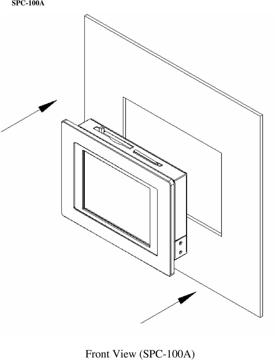
16 SPC can be mounted on walls less than 4mm thick Rear View (SPC-100A)

17 Front View for Panel Mount (SPC-100A) Unit: mm
")
18 1.8 Dimension and cutout SPC-100C

19 SPC-100A

20 CH APTER 2 Getting Start This chapter provides brief instructions for operating the SPC

21 2.1 Quick Starting Step1: Unpack the SPC-100 from its packing. Please check the packing list at the beginning of this manual. Step2: Connect the power connector to 10 ~ 28V DC power source. The power source can either be from a power adapter or an in-house power source. Step3: Connect the power source to the system power supply. Step4: Plug in the power lines and turn on the system power switch, you will see the Welcome screen of Windows CE.NET. Then you can start to use SPC-100. Step5: Turn on the power switch. Step6: Calibrate the touchscreen. 21
22 2.2 Supplying Power to SPC 1. SPC accepts only DC power, not AC power 2. The DC input range for SPC is 10V ~ 28V. 3. Install the Vcc cable and GND cable into the male power connector (male power connector is in the package of SPC) Vcc GND 22
23 4. Plug the male power connector into female power connector in SPC. Vcc GND 23
24 5. Turn on the power switch 24
25 CHAPTER 3 The Engine of the SPC-100 This chapter will descript hardware s connectors of the SPC
26 This chapter will descript hardware connectors of the SPC-100, the pin definition and power system. 3.1.SPC-100 Connector Table The following table is the information for SPC-100 s connectors. Table 3.1 Connector Table Label Function CN 1 COM1 RS-232 Full transceiver level port CN 3 Ethernet 10/100 base-t RJ-45 port CN 6 Audio Line out jack CN13 Video-in port (Reserve function) CN 15 PCMCIA(CardBus) slot type II CN 23 COM3 RS wire TTL level port CN 25 COM2 RS-232 Full 9 pin transceiver level port CN 26 2 port USB Host 1.1 CN 27 2 port USB Host 1.1 CN 28 Power-in connector (5.08mm Phoenix conn.) 3.2.Connectors pin definition of the SPC-100 CN 1: RS-232 serial port Pin Signal 1 DCDR 2 RXDR 3 TXDR 4 DTRR 5 GND 6 DSRR 7 RTSR 8 CTSR 9 RIR Figure 3.1 COM1 (RS-232) serial port 26
27 CN 25: RS-232 serial port Pin Signal 1 DCDR 2 RXDR 3 TXDR 4 DTRR 5 GND 6 DSRR 7 RTSR 8 CTSR 9 RIR Figure 3.2 COM2 (RS-232) serial port CN 6 : Audio (Line-out) port Pin Signal 1 Right channel 2 Left channel 3 GND Figure 3.3 Audio(Line-out) port CN 26 : 2 port 1.1USB Host port Pin Signal 1 USBV1 2 USB1_N 3 USB1_P 4 GND 5 USBV2 6 USB2_N 7 USB2_P 8 GND 27
28 Figure port USB Host port CN 27 : 2 port 1.1USB Host port Pin Signal 1 USBV1 2 USB1_N 3 USB1_P 4 GND 5 USBV2 6 USB2_N 7 USB2_P 8 GND Figure port USB Host port CN 3 : RJ-45 for Ethernet port Pin Signal 1 TPTX100P 2 TPTX100N 3 TPRX100P 4 N/C 5 N/C 6 TPRX100N 7 N/C 8 N/C 9 GND 10 GND 11 LED1+ 12 nenet0_link_led 13 LED2+ 14 nenet0_ nspeed_led 28
29 Figure 3.6 RJ-45 for Ethernet port CN 28 : Power Connector Pin Signal 1 VDC (+) 2 VDC (-) 3 GND 3.2.Power System of the SPC-100 Figure 3.7 Power connector Users can only use a Terminal Block 5.08mm 3P MALE (Advantech PN: , the vendor : DINKLE,The DINKLE PN : 2ESDVM-03P) 19Vdc power adapter to be SPC-100 s power input.spc-100 Power input range is DC 10-28V.Power consumption is 11W in normal mode and 6.5W in idle mode There is one 3.0V, coin-type rechargeable backup battery on SPC-100. This coin battery is mainly for external RTC of the SPC-100. When the power switch is on, the external DC power will automatically charge this coin battery. 29
30 CHAPTER 4 Software Functionality This chapter details the Windows CE.NET operating system on the Sections include: Introduction Windows CE Startup Procedure Upgrade Procedure Utilities Network M-system DOC Flash File System Application Program Development Windows CE.NET 4.2 Require Components 30
31 4.1 Introduction The SPC series is one embedded system with Windows CE.NET OS. The Windows CE.NET is a compact OS that occupies less storage space or system resources compared with other operating systems such as Windows NT or Windows XP. By its modular nature, it is possible to choose those functions that are useful for specific application. Not only reducing the system resources required, but also reduces start-up time. In the field of embedded applications, this is an appealing feature because the impact of downtime would be minimized. Furthermore, the small storage space it needs makes OS on solid-state disk possible, which implies higher robustness to harsh environments. Figure 4.1 Windows CE.NET on the SPC Series 4.2 Windows CE Startup Procedure Windows CE can be loaded by two methods, one is through on-board flash(default), the other is through Ethernet. After setting HyperTerminal on PC side and connecting Null modem cable between PC Com port and SPC-100 COM1, user can get the boot-up message and configure the method to download Windows CE image. 31
32 4.2.1 Setup HyperTerminal on PC Step1. Execute HyperTerminal Figure 4.2 Execute HyperTerminal from Start menu 32
33 Step2. Name HyperTerminal, and then press OK Figure 4.3 Naming HyperTerminal 33
34 Step3. Choose used COM port on PC, and then press OK Figure 4.4 Choose HyperTerminal COM port 34
35 Step4. Setup HyperTerminal contents. Baud Rate = 38400, Data Bits = 8, Parity = None, Stop Bits = 1, Flow Control = None. And then press OK. Figure 4.5 Configure COM port parameters Now, HyperTerminal is working Use Null modem cable to link HyperTerminal COM port and SPC-100 COM1 User can get the SPC-100 COM1 location from Chapter 3 in this manual Choose download image method from HyperTerminal Step1. Power on SPC
36 Step2. Press SPACE to enter EBOOT Configuration Options window when the HyperTerminal shows the screen below. Figure 4.5 SPC-100 boot up window 36
37 Step3. Configure EBOOT Configuration Options -- Option(0) IP address Figure 4.5 SPC-100 Eboot Configuration Options window Choosing this option allows the configuration of the static IP address that is used if DHCP is not enabled. This information is configured once and stored into flash for subsequent downloads. The following prompt is displayed: Enter new IP address: You should enter a decimal representation of the IP address with each byte separated by a decimal point. If you enter no data at the prompt, the IP address is not changed. If you enter any numbers, they are used. Any numbers not entered are expanded to zeros. That is, entering at the prompt resolves to Option (1) Subnet Mask Choosing this option allows the configuration of the subnet mask that is used in combination with the static IP address. Just like the IP address, this information is configured once and stored into flash for subsequent downloads. The following prompt is displayed: 37
38 Enter new subnet mask: You should enter a decimal representation of the mask with each byte separated by a decimal point. If you enter no data at the prompt, the mask is not changed. If you enter any numbers, they are used. Any numbers not entered are expanded to zeros. That is, entering at the prompt resolves to Option (2) NPE0 MAC Address Choosing this option allows the configuration of the static MAC address that is used for NPE0 Interface. This information is now configured once and stored into flash for subsequent downloads. The following prompt is displayed: Enter new MAC address: You should enter a hexidecimal representation of the MAC address with each byte separated by a dash. If you enter no data at the prompt, the MAC address is not changed. If you enter any numbers, they are used. Any numbers not entered are expanded to zeros. That is, entering AA at the prompt resolves to AA Option (3) NPE1 MAC Address This option is not used on SPC Option (4) RNDIS MAC Address This option is not used on SPC Option (5) Boot Delay Choosing this option allows the configuration of the number of seconds that the boot loader waits for user input before continuing with the image download or launch. The following prompt is displayed: Enter maximum number of seconds to delay [1-255]: -- Option (6) DHCP Choosing this option cycles between enabling and disabling the use of DHCP. When DHCP is enabled the static IP address is not used. When DHCP is disabled, the static IP address is used. 38
39 -- Option (7) Program RAM Image into Flash Choosing this option instructs the boot loader to store a normal NK.BIN RAM image into flash memory. This image may be launched via option (L). When launched, the boot loader reads the entire image out of flash and stores it into the appropriate location within SDRAM. It then executes this image from SDRAM exactly the same way it would have had it downloaded the image into RAM and never stored it into flash. Because the image runs completely out of SDRAM, system performance is improved due to the faster access speeds associated with this memory type. -- Option (8) Check Image Signature(s) Choosing this option will check the signature of the downloaded binary image. Note that the released image is not signed so this is expected to fail. -- Option (A) Automatic Startup Behavior Choosing this option cycles the default boot behavior from downloading a new image at startup to launching the existing flash resident image. The existing flash image is the flash image that is programmed when an NK.BIN image is programmed into flash. -- Option (B) Boot Device Order This option is not used in SPC-100. The always boot device is NPE0. -- Option (C) Ethernet Debugging This option is not used in SPC-100. Must keep it DISABLE. -- Option (D) Download Image Now Choose this option to break out of the menu, save any applicable changes that were made and then continue with the image download process. -- Option (F) Format Flash Choose this option to format the flash. This will not overwrite EBOOT or EBOOT parameters. -- Option (L) Launch Existing Flash Resident Image Now Choose this option to break out of the menu, save any applicable changes that were made and then launch the previously programmed flashed image. -- Option(M) Display Mode Setup, Mode(0) now!! ---Mode(0)(800x600), Mode(1)(640x480), Mode(2)(1024x768),Mode(3)(320x24) Choose this option to configure the display resolution. In default in SPC-100, this option is set as Mode(0) 800x
40 -- Option (R) Reset to Factory Default Configuration Choosing this option resets the user-configurable settings to their factory defaults. IP address: Subnet mask: NPE0 MAC Address: NPE1 MAC Address: RNDIS MAC Address: Boot delay: DHCP: Program RAM image into FLASH: Check image signature(s): Automatic Startup Behavior: Boot device order: Ethernet debugging: 5 seconds Enabled Disabled Disabled Download new image via Ethernet PCI NIC RT8139D -> NPE0 -> NPE1 Enabled Note: When you reset the user-configurable settings, you must change option(c) Ethernet debugging setting from Enable to Disable for boot-up Windows CE successfully. Configure EBOOT configuration examples: Ex1: Launch on-board flash image Do not enter EBOOT Configuration menu, or in EBOOT Configuration menu choose option(l) to launch on-board flash image Ex2: Download Windows CE image from Ethernet without programming image into Flash 1. Configure option(7) as DISABLE 2. Choose option(d) to start downloading image Ex2: Download Windows CE image from Ethernet with programming image into Flash 1. Configure option(7) as ENABLE 2. Choose option(d) to start downloading image 40
41 4.3 Upgrade Procedure After the OS image was built, we may want to burn it to the on-board flash ROM. Advantech provides the upgrade utility UpgradeIXP_ exe to upgrade Bootloader image, WinCE image or boot logo to onboard flash ROM. The upgrade procedure is described as following : Step1. Copy UpgradeIXP_ exe utility and image files you want (for example, NK.NB0, EBOOT.NB0, and WINDOWSCE.BMP ) to CF storage card. Note : NK.NB0 is WinCE image. EBOOT.NB0 is Bootloader image. WINDOWSCE.BMP is boot bitmap. Step2. Insert CF storage card to platform, and then launch UpgradeIXP_ exe. Figure 4.6 Image files and upgrade utility in CF storage card Step3. Check the items you want to upgrade as the figure shown in Figure 4.7. If you want to upgrade boot logo, you can input the path of the bitmap file in the edit box or click Browse button to select the file. Note: The difference between NK.NB0 (Compressed) and NK.NB0 (Normal, XIP) : The option NK.NB0 (Normal, XIP) means that the nk.nb0 will be upgraded directly to the flash ROM, and NK.NB0 (Compressed) means that we compress nk.nb0 first, and then write the compressed data to the flash ROM. : (1) Boot time : compressed image take more time in system bootup. (2) Flash file system size : compressed OS image would result in larger flash file system size. Step4. Press Apply button on the dialog. Then the items you select will be upgraded to the flash ROM. See Figure
42 Figure 4.7 Press Apply button in order to upgrade onboard flash ROM After the upgrade process done, reboot system Utilities There are several useful utilities added in the standard Windows CE.NET OS: System Configurator System Configurator is an outstanding utility designed by Advantech Windows CE.NET software team. It is an integrated environment where user can get useful system information as well as configure favorite system settings and apply system control function on demand. Double click the icon of System Configurator on the desktop. Following sections illustrate the functions of System Configurator General The memory information including DRAM, and FLASH file system are displayed in the General page. And the versions of each part of the installed embedded OS, including Windows CE.NET, Bootloader and System Configurator respectively. 42
43 Figure 4.8 General information Calibration The Touch-screen page provides the calibration function. Click the "calibration" button, the "Stylus Properties" windows would appear. Then click "calibrate" button in the Stylus Properties window to enter calibration process. In the calibration process, user taps on the center of the target on the screen then the target will move to the next position. After calibration, user needs to save the registry to store the calibration data manually. About registry save, please see section for detail description. Figure 4.9 Touch-screen calibration 43
44 Display From time to time it is unnecessary to turn on the display attached to the SPC all the day. The Display page provides two frequently used functions, one is the display resolution and the other is brightness adjusting.. Figure 4.10 Display configuration NOTE: User can set the idle time to turn off backlight automatically from the backlight page of Display Properties of Control Panel. When backlight is off, there were three inputs to turn it on: (1) mouse; (2) keyboard; (3) touch-screen. Figure 4.11 Display Properties setting window 44
45 WatchDog timer It is important in industrial applications that the control systems are rarely crashed, or are capable of self-reset if they are halted somehow. Watchdog function of automatic resetting system is therefore provided in SPC. There is a timer inside the watchdog function. User s AP could invoke the associated APIs in Watchdog function to start the timer, then Watchdog function would repeat the countdown of the specified period of time to reboot the system if the user s AP does not clear the timer in time periodically. The Watchdog function in the SPC provides eight different time intervals: 2 seconds, 5 seconds, 10 seconds, 30 seconds, 60 seconds, 2 minutes, 5 minutes and 10 minutes. The Test" button is used to start the Watchdog count down function, and the Enable Trigger button is used to trigger the Watchdog periodically. Figure 4.12 Watchdog timer Miscellaneous The Misc page provides several functions as described below. The "Registry" block provides registry save, clear and registry view function. The "MAC ID" block shows the network MAC address. The "COMM" block provides the communication function IPConfig. The Reset Block provides Cold Boot and Start Upgrade functions. Cold Boot is used to reboot system. Start Upgrade is used to automatically download image from Ethernet and program image into flash after system reboot. 45
46 Figure 4.13 Miscellaneous settings Startup execution The SPC has one useful function call "Startup execution". After the system boot up, the startup execution function would automatically perform. This function is useful for control system to do the initialization processes or some other procedures. In SPC, there is one way to perform "Starup" function. Method: Step1: Create "startup" directory in CF storage card or in folder "\Mounted Volume\". Step2: Copy executable files to "startup" directory that is created by Step 1. Example: We copy the executable files "tty.exe" in "\Mounted Volume\Startup", and then reboot the system. After the system boot up, "tty.exe" would be automatically executed. 46
47 4.5 Network Networking via Ethernet SPC build in one 100Base-T Ethernet controller. It appears at Control Panel/Network and Dial-up Connections via IXP425ETHNPE1. User can configure its Ethernet support as follows: 1. Click "Start/Settings/Control Panel" 2. Double click "Network and Dial-up Connections" 3. This window will display all available connections. Pressing the connection icon, its pop-up menu appears and users could disable, rename or modify properties from there. 4. If the SPC is a node of the LAN with DHCP servers, it is now available. 5. If the SPC is a node of the LAN with fixed IP, the user has to consult with MIS to get specific IP addresses. Then fill them into the associated fields of the Properties Dialog that could be popped up by the properties item of the step 3 above. Then use System Configurator\Misc\Registry\Save on the desktop to save this changed registry. Reboot the system, the Ethernet functions would be available as previous configuration. Figure 4.14 Networking via Ethernet 47
48 4.5.2 Networking via PPP The SPC supports PPP protocol. To setup and utilize it, follow the steps below: 1. Click "Start/Settings/Network and Dial-up Connections 2. Make a new connection. As the dialogue box pops out, choose the "Dial-Up Connection". Click "Next". 3. Click "Configure" to setup the device according to the specification of your modem, and then click "OK" on the top-right corner of the window. 4. Click "Next". Input the telephone number in the "Phone Number" window. Press "Finish" to complete the setup process. 5. Turn on your modem and use RS-232 cable to connect modem and COM1 of SPC series. 6. Double click the connection you have made in Step 4. Key in the user name, password and domain for the dial-up connection and press "Connect". Figure 4.15 Networking via PPP Web browser The SPC builds-in Windows CE OS includes IE Browser. It can be used to browse web pages on World Wide Web via LAN or PPP. 48
49 4.6 M-system DOC Flash File System Introduction to M-system DOC Flash File System M-system DOC Flash File System was designed and developed specifically as an enhancement to Microsoft Windows CE operating systems and eliminates extra disk-like storage such as storage cards, redundant RAM and ROM Mounted Volume folder in SPC-100 SPC uses M-system DOC Flash to utilize the free space of flash ROM for persistent storage. The M-system DOC Flash file system region in the system is located in "\Mounted Volume" directory. Any file or directory stored in "\Mounted Volume" directory would be keep persistently, even if the power of SPC were turned off. The user can store software or data in \Mounted Volume rather in CF card to avoid inconvenience. 49
50 4.7 Application Program Development The SPC is bundled with built-in Windows CE.NET operating system. In real application user need to execute various application programs on it. However, unlike its other CPU family, the Windows CE.NET is a hardware-dependent operating system. That is to say, Windows CE.NET application programs are only portable in the source code level. Users must rebuild the runtime file for a different Windows CE.NET platform even though the source code may not be changed at all System requirements Intel Pentium-90 CPU or more advanced Microsoft Windows 2000 Professional or Windows XP Microsoft embedded Visual Tools 4.0 Platform SDK for SPC 64MB DRAM CD-ROM drive Monitor with VGA resolution at least Mouse 200MB free hard disk space at least SPC series platform Let the host PC and SPC connect on the same LAN to do kernel debugging if necessary USB cable (bundled in the standard SPC series) Building Windows CE program By the platform SDK bundled with the standard SPC, users can build the Windows CE runtime application program by the embedded Visual Tools. 50
51 Figure 4.16 Flow-chart of Building Windows CE.NET runtime How to install SDK Copy SPC SDK file ADV_IXP_SDK.msi to your PC, and launch it. You can install SDK by steps. Step 1, Launch SPC SDK file, and then tap Next button. Figure
52 Step 2, Accept License Agreement and go next. Figure
53 Step 3, Key in your information and go next. Figure
54 Step 4, Choose setup type. There are 3 options Embedded Visual C++, Microsoft.NET Compact Framework, and Documentation in Custom Setup. Figure
55 Figure 4.21 Step 5, Tap Install button to install SDK. Figure
56 Install SDK. Figure 4.23 Step6, Finish installing. 56
57 Figure
58 4.7.4 Running your application programs ActiveSync would automatically transfer the built application program to platform. Choose SDK type as SOM_A once compile your application program. Figure
59 4.8 Windows CE.NET 4.2 Require Components (Advantech Recommend) Applications and Services Development (: with; : without) Feature Active Template Library (ATL) C Libraries & Runtimes Component Services (COM) Device Management Lightweight Directory Access Protocol (LDAP) Message Queuing (MSMQ) Microsoft Foundation Classes (MFC) Object Exchange Protocol (OBEX) Pocket Outlook Object Model (POOM) API Simple Object Access Protocol (SOAP) Toolkit Standard SDK for Windows CE.NET.NET Compact Framework XML Default Selection Applications End User Feature ActiveSync File Viewers Help Inbox Remote Desktop Connection Terminal Emulator Windows Messenger WordPad Default Selection Core OS Services Feature Serial Port Support Parallel Port Support USB Host Support Debugging Tools Power Management Default Selection 59
60 Kernel Features Communication Services and Networking Feature Networking Features Networking - Local Area Network (LAN) Networking - Personal Area Network (PAN) Networking - Wide Area Network (WAN) Servers (HTTPD) Default Selection File Systems and Data Store Feature Storage Manager File & Database Replication (Bit-based) File System Internal (RAM & ROM File System) Registry Storage (RAM-based Registry) Default Selection Fonts Feature Arial Comic Sans MS Courier New Georgia Impact Kino MSLogo Symbol Tahoma Times New Roman Trebuchet MS Verdana Webdings Wingding Default Selection International Feature Locale Services Default Selection 60
61 Locale Specific Support (Input Method Selector Sample Application) Multilingual User Interface (MUI) Internet Client Services Feature Default Selection Browser Application (Internet Explorer 5.5 for Windows CE - Standard Components) Internet Explorer 5.5 for Windows CE Components - Internet Explorer Browser Control Host - Internet Explorer HTML/DHTML API - Internet Explorer Multiple-Language API - Internet Explorer TV-Style Navigation - URL Moniker Services - Windows Internet Services Pocket Internet Explorer HTML View (WEBVIEW) Sample IE 5.5 Internet Options Control Panel Scripting Multimedia Technologies Feature Basic Multimedia Default Selection Multimedia Components - Audio - DirectMusic - Digital Rights Management - Direct3D - DirectDraw - DirectShow - DVD-Video - Windows Media Player - Windows Media Technologies Security Feature Authentication Services (SSPI) Cryptography Services (CryptoAPI 1.0) with High Encryption Provider Default Selection 61
62 Shell and User Interface Feature Default Selection Shell User Interface - Accessibility - Customizable UI - Mouse - Touch Display (Stylus) - Network User Interface - Overlapping Menus - Software Input Panel - Speech Interface 62
63 63
IPC-610. Industrial PC Chassis
 IPC-610 Industrial PC Chassis Copyright Notice This document is copyrighted, September 1998, by Advantech Co., Ltd. All rights are reserved. Advantech Co., Ltd. reserves the right to make improvements
IPC-644. Micro-Box 4-slot Industrial Chassis. User Manual
 IPC-644 Micro-Box 4-slot Industrial Chassis User Manual Copyright Notice Advantech Co., Ltd copyrights this documentation and the software included with this product in December, 2005. All rights are reserved.
TL-PS310U Single USB 2.0 Port MFP and Storage Server
 TL-PS310U Single USB 2.0 Port MFP and Storage Server Rev: 2.0.0 1910010313 Contents Chapter 1 Introduction... 1 1.1 Product Overview...1 1.2 Network Management...1 1.3 Components and Features...1 1.4 Hardware
WUA-0605 300Mbps Wireless USB Network Adapter
 WUA-0605 300Mbps Wireless USB Network Adapter User Manual V1.0 Certification FCC CE FCC Statement This equipment has been tested and found to comply with the limits for a Class B digital device, pursuant
Ultra Thin Client TC-401 TC-402. Users s Guide
 Ultra Thin Client TC-401 TC-402 Users s Guide CONTENT 1. OVERVIEW... 3 1.1 HARDWARE SPECIFICATION... 3 1.2 SOFTWARE OVERVIEW... 4 1.3 HARDWARE OVERVIEW...5 1.4 NETWORK CONNECTION... 7 2. INSTALLING THE
User Manual. PePWave Surf / Surf AP Indoor Series: Surf 200, E200, AP 200, AP 400. PePWave Mesh Connector Indoor Series: MC 200, E200, 400
 User Manual PePWave Surf / Surf AP Indoor Series: Surf 200, E200, AP 200, AP 400 PePWave Mesh Connector Indoor Series: MC 200, E200, 400 PePWave Surf AP Series: Surf AP 200-X, E200-X, 400-X PePWave Surf
User Manual Web Operating Panel AP User Manual. General Settings, Updating and Troubleshooting
 User Manual Web Operating Panel AP User Manual General Settings, Updating and Troubleshooting Copyright The documentation and the software included with this product are copyrighted 2010 by Advantech Co.,
dedicated KVM switch and rackmount screen technology User Manual IP-S101 Combo KVM Extender Designed and manufactured by Austin Hughes
 dedicated KVM switch and rackmount screen technology User Manual IP-S101 Combo KVM Extender Designed and manufactured by Austin Hughes 751 Legal Information First English printing, October 2002 Information
WinCON8000-R2/R8. Hardware User s Manual
 WinCON8000-R2/R8 Compact Embedded Controller Hardware User s Manual REV 1.1 2004/10/22 1 Warranty All products manufactured by ICP DAS are warranted against defective materials for a period of one year
USB 2.0 to 10/100Mbps Ethernet Adapter UE-9521. User Manual
 USB 2.0 to 10/100Mbps Ethernet Adapter UE-9521 User Manual 1 Copyright Copyright 2004 by PLANET Technology Corp. All rights reserved. No part of this publication may be reproduced, transmitted, transcribed,
DSL-502G ADSL Ethernet/USB Router User s Guide
 DSL-502G ADSL Ethernet/USB Router User s Guide (March 2002) 651DSL500055 Wichtige Sicherheitshinweise 1. Bitte lesen Sie sich diese Hinweise sorgfältig durch. 2. Heben Sie diese Anleitung für den spätern
Business Audio System: Music & Messaging MP3 Player. by Grace Digital Audio. User Guide. Model No. GDI-USBM10
 Business Audio System: Music & Messaging MP3 Player by Grace Digital Audio User Guide Model No. GDI-USBM10 User Guide Contents Introduction 2 Safety & General Use Information 2 Features 3 Set Up & Operation
IEEE 802.11b WLAN PC Card
 IEEE 802.11b WLAN PC Card User s Guide Version: 1.3 August 2001 Please install the Utility/Driver first before inserting the PCMCIA Card. FCC Class B Radio Frequency Interference Statement The manufacturer
Installation Guide 1-port USB 2.0 Print Server 1 GPSU21
 Installation Guide 1-port USB 2.0 Print Server 1 GPSU21 2 Welcome Thank you for purchasing this 1-port USB 2.0 Print Server that allows any networked computer to share a USB printer. It complies with USB
User Manual. EtherUSB
 User Manual EtherUSB USB Ethernet Access Point for PDA V 2.0 Clarinet Systems, Inc. Clarinet Systems, Inc. http://www.clarinetsys.com Page 1 Publication Revision No. Control Table Rev. No. Date Contents
Table of Contents. Chapter1. Introduction...1. 1.1 Before Installation... 1 1.2 System Requirements... 1
 Table of Contents Chapter1. Introduction...1 1.1 Before Installation... 1 1.2 System Requirements... 1 Chapter2. IVS-110 1-Channel Internet Video Server...2 2.1 Package Content... 2 2.2 Physical Installation...
2100 POS System. 2100 User Guide
 2100 POS System 2100 User Guide Thank you for selecting UTC RETAIL s innovative Model 2100 Point of Sale solution! This guide is designed to acquaint you with the features and functionality of the 2100
mysensors mysensors Wireless Sensors and Ethernet Gateway Quick Start Guide Information to Users Inside the Box mysensors Ethernet Gateway Quick Start
 mysensors Information to Users mysensors Wireless Sensors and Ethernet Gateway Quick Start Guide This equipment has been tested and found to comply with the limits for a Class B digital devices, pursuant
TCP/IP MODULE CA-ETHR-A INSTALLATION MANUAL
 TCP/IP MODULE CA-ETHR-A INSTALLATION MANUAL w w w. c d v g r o u p. c o m CA-ETHR-A: TCP/IP Module Installation Manual Page Table of Contents Introduction...5 Hardware Components... 6 Technical Specifications...
CONSOLE REMOTE I /O AC 9V
 CONSOLE CONSOLE REMOTE I /O AC 9V AC 9V REMOTE I /O User Manual CE-220 Read this guide thoroughly and follow the installation and operation procedures carefully in order to prevent any damage to the units
RouteFinder SOHO. Quick Start Guide. SOHO Security Appliance. EDGE Models RF825-E, RF825-E-AP CDMA Models RF825-C-Nx, RF825-C-Nx-AP
 RouteFinder SOHO SOHO Security Appliance EDGE Models RF825-E, RF825-E-AP CDMA Models RF825-C-Nx, RF825-C-Nx-AP Quick Start Guide RouteFinder RF825 Series Quick Start Guide RouteFinder SOHO Security Appliance
xpico Wi-Fi Embedded Device Server Evaluation Kit Quick Start Guide
 xpico Wi-Fi Embedded Device Server Evaluation Kit Quick Start Guide Part Number 900-685 Revision A June 2013 Copyright and Trademark Contacts 2013 Lantronix, Inc.. All rights reserved. No part of the contents
Installation Guide. APA-1460 SlimSCSI. PCMCIA-to-SCSI Host Adapter
 R Installation Guide APA-1460 SlimSCSI PCMCIA-to-SCSI Host Adapter Introduction This document explains how to install and use Adaptec s APA -1460 SlimSCSI PCMCIA-to-SCSI adapters. The SlimSCSI adapters
EPSON USB/Parallel Adapter User s Guide
 EPSON USB/Parallel Adapter User s Guide EPSON Stylus COLOR 440 EPSON Stylus COLOR 800 EPSON Stylus COLOR 600 EPSON Stylus COLOR 850 EPSON Stylus COLOR 640 EPSON Stylus COLOR 1520 EPSON Stylus Photo EX
Ethernet Radio Configuration Guide
 Ethernet Radio Configuration Guide for Gateway, Endpoint, and Repeater Radio Units April 20, 2015 Customer Service 1-866-294-5847 Baseline Inc. www.baselinesystems.com Phone 208-323-1634 FAX 208-323-1834
Wave/PC Interactive System USB Adapter Kit. Installation Guide
 Wave/PC Interactive System USB Adapter Kit Installation Guide Safety Information 1. Read these instructions for all components before using this product. 2. Keep these instructions for future reference.
Installation Guide Wireless 4-Port USB Sharing Station. GUWIP204 Part No. M1172-a
 Installation Guide Wireless 4-Port USB Sharing Station 1 GUWIP204 Part No. M1172-a 2011 IOGEAR. All Rights Reserved. PKG-M1172-a IOGEAR, the IOGEAR logo, MiniView, VSE are trademarks or registered trademarks
PCMCIA Wireless LAN Card User s Manual
 PCMCIA Wireless LAN Card User s Manual Rev 1.0 Regulatory compliance FCC Warning This equipment has been tested and found to comply with the limits for a Class B digital device, pursuant to part 15 of
Cisco 831 Router and Cisco SOHO 91 Router Cabling and Setup Quick Start Guide
 English CHAPTER 1 Cisco 831 Router and Cisco SOHO 91 Router Cabling and Setup Quick Start Guide Cisco One-Year Limited Hardware Warranty Terms Easy Installation: Try These Steps First! (CRWS Users) Overview
IP Camera (L series) User manual 2013-05 V1.1
 User manual 2013-05 V1.1") Dear users, the configuration for this camera is professional, so please read the user manual carefully before using the camera. IP Camera (L series) User manual 2013-05 V1.1 Statement If the user manual
Dear users, the configuration for this camera is professional, so please read the user manual carefully before using the camera. IP Camera (L series) User manual 2013-05 V1.1 Statement If the user manual
IOVU-571N ARM-based Panel PC
 IOVU-571N ARM-based Panel PC Features RISC-based Panel PC IOVU-57N Application Dimensions Ordering Information Specifications ARM-based Panel PC IOVU-571N Serial IOVU software support Packing List Options
USB 2.0 VGA ADAPTER USER MANUAL
 USB 2.0 VGA ADAPTER USER MANUAL CONTENTS INTRODUCTION... 3 FEATURES... 3 SYSTEM REQUIREMENTS... 3 PACKAGE CONTENTS... 3 SUPPORTED COMMON DISPLAY RESOLUTION... 4 TECHNICAL SPECIFICATIONS... 4 INSTALLATION
FB-500A User s Manual
 Megapixel Day & Night Fixed Box Network Camera FB-500A User s Manual Quality Service Group Product name: Network Camera (FB-500A Series) Release Date: 2011/7 Manual Revision: V1.0 Web site: Email: www.brickcom.com
DIRECT INTERNET DATA. User s Guide
 DIRECT INTERNET DATA User s Guide Iridium Satellite LLC Rev. 2; June 15, 2001 DIRECT INTERNET DATA ------------------------------------------------------------------------------------- TABLE OF CONTENTS
USB2VGA. Instruction Manual. USB to VGA Adapter. USB 2.0 to VGA External Multi Monitor Video Adapter
 USB to VGA Adapter USB2VGA Instruction Manual USB 2.0 to VGA External Multi Monitor Video Adapter FCC Compliance Statement This equipment has been tested and found to comply with the limits for a Class
Quick Start Guide. WRV210 Wireless-G VPN Router with RangeBooster. Cisco Small Business
 Quick Start Guide Cisco Small Business WRV210 Wireless-G VPN Router with RangeBooster Package Contents WRV210 Router Ethernet Cable Power Adapter Product CD-ROM Quick Start Guide Welcome Thank you for
Additional Requirements for ARES-G2 / RSA-G2. One Ethernet 10 Base T/100 Base TX network card required for communication with the instrument.
 TA Instruments TRIOS Software Installation Instructions Installation Requirements Your TRIOS Instrument Control software includes all the components necessary to install or update the TRIOS software, as
LabelWriter. Print Server. User Guide
 LabelWriter Print Server User Guide Copyright 2010 Sanford, L.P. All rights reserved. 08/10 No part of this document or the software may be reproduced or transmitted in any form or by any means or translated
3.5 EXTERNAL NETWORK HDD. User s Manual
 3.5 EXTERNAL NETWORK HDD User s Manual Table of Content Before You Use Key Features H/W Installation Illustration of Product LED Definition NETWORK HDD Assembly Setup the Network HDD Home Disk Utility
SoftRAID 5 QUICK START GUIDE. for OWC ThunderBay
 SoftRAID 5 QUICK START GUIDE for OWC ThunderBay TABLE OF CONTENTS INTRODUCTION...1 1.1 MINIMUM SYSTEM REQUIREMENTS 1.2 FEATURES 1.3 ABOUT THIS MANUAL SYSTEM SETUP...2 2.1 GETTING STARTED 2.2 INITIALIZING,
Product Description. Licenses Notice. Introduction TC-200
 User Manual TC-200 Introduction TC-200 Product Description The TC-200 provides the fastest Thin Client performance on the market, It runs embedded Linux, swing user interface, Citrix 6.3, Microsoft RDP
User Manual USB Laptop KVM Switch. GCS661U Part No. M1069
 User Manual USB Laptop KVM Switch 1 GCS661U Part No. M1069 2 Table of Contents User Notice 4 A Note About Terminology 5 Overview 6 Features 7 Package Contents 8 Requirements 9 Operating System Support
USB KVM Switch USER MANUAL CS62US / CS64US
 USB KVM Switch USER MANUAL CS62US / CS64US EMC Information FEDERAL COMMUNICATIONS COMMISSION INTERFERENCE STATEMENT: This equipment has been tested and found to comply with the limits for a Class B digital
Wireless Router Setup Manual
 Wireless Router Setup Manual NETGEAR, Inc. 4500 Great America Parkway Santa Clara, CA 95054 USA 208-10082-02 2006-04 2006 by NETGEAR, Inc. All rights reserved. Trademarks NETGEAR is a trademark of Netgear,
USB to RS-422/485 Serial Adapter (ID-SC0911-S1/SC0A11-S1) User s Manual
 User s Manual") USB to RS-422/485 Serial Adapter (ID-SC0911-S1/SC0A11-S1) User s Manual 1 Copyright Statement No part of this publication may be reproduced in any form by any means without the prior written permission.
USB to RS-422/485 Serial Adapter (ID-SC0911-S1/SC0A11-S1) User s Manual 1 Copyright Statement No part of this publication may be reproduced in any form by any means without the prior written permission.
Touch Panel Computers
 Touch Panel Computers 3 Selection Guides Touch Panel Computer Selection Guide 3-2 TPC-1570H (New) Intel Celeron M Touch Panel Computer with 15 high luminance XGA TFT LCD 3-4 TPC-1261H (New) AMD GX3 Touch
USB VoIP Phone Adapter. User s Manual
 USB VoIP Phone Adapter User s Manual FCC Certifications This Equipment has been tested and found to comply with the limits for a Class B digital device, pursuant to part 15 and part 68 of the FCC Rules.
User Manual. EtherUSB
 User Manual EtherUSB USB Ethernet Access Point for PDA V 1.6 Page 1 Publication Revision No. Control Table Rev. No. Date Contents 1.6 8/22/07 Support connection of multiple WM5.0 devices 1.5 6/18/07 Support
WinCon-8000. Programmable Automation. Controller
 Programmable Automation Controller Introduction The is a leading edge embedded platform with Intel Strong ARM CPU running the Windows CE.NET operating system. When compared to the standard Windows OS,
Disclaimers. Important Notice
 Disclaimers Disclaimers Important Notice Copyright SolarEdge Inc. All rights reserved. No part of this document may be reproduced, stored in a retrieval system, or transmitted, in any form or by any means,
Point of View Mobii 10 Tegra Tablet. Notice... 2
 TABLE OF CONTENTS Notice... 2 1.0 Preface... 2 2.0 Getting to know the basics... 4 3.0 How to Start... 7 3.1 Home Shell... 7 3.1.1 Home Shell > Widgets (Search RSS Weather)... 8 3.1.2 Home Shell > Widgets,
EPSON USB/Parallel Adapter User s Guide
 EPSON USB/Parallel Adapter User s Guide EPSON Stylus COLOR 440 EPSON Stylus COLOR 1520 EPSON Stylus COLOR 600 EPSON Stylus COLOR 3000 EPSON Stylus COLOR 640 EPSON Stylus Photo 700 EPSON Stylus COLOR 660
USB 2.0 Peripheral Switch USER MANUAL US221A / US421A
 USB 2.0 Peripheral Switch USER MANUAL US221A / US421A FCC Information This equipment has been tested and found to comply with the limits for a Class B digital device, pursuant to Part 15 of the FCC Rules.
Professional USB to Serial Adapter Hub with COM Retention
 Professional USB to Serial Adapter Hub with COM Retention ICUSB2321X ICUSB2322X ICUSB2324X *actual product may vary from photos *actual product may vary from photos DE: Bedienungsanleitung - de.startech.com
Operating Instructions
 Operating Instructions (For Setting Up) Digital Imaging Systems Installation Overview Model No. DP-8060 / 8045 / 8035 Table of Contents Setting Your Machine Installation Overview General Installation Overview...
Quick Installation. A Series of Intelligent Bar Code Reader with NeuroFuzzy Decoding. Quick Installation
 Quick Installation A Series of Intelligent Bar Code Reader with NeuroFuzzy Decoding This chapter intends to get your new FuzzyScan scanner working with your existing system within minutes. General instructions
SA-9600 Surface Area Software Manual
 SA-9600 Surface Area Software Manual Version 4.0 Introduction The operation and data Presentation of the SA-9600 Surface Area analyzer is performed using a Microsoft Windows based software package. The
xpico Wi-Fi Embedded Device Server Evaluation Board Quick Start Guide
 xpico Wi-Fi Embedded Device Server Evaluation Board Quick Start Guide Part Number 900-685 Revision B December 2014 Copyright and Trademark Contacts 2014 Lantronix, Inc.. All rights reserved. No part of
TE100-PS1 Ethernet / Fast Ethernet Multiprotocol Print Server
 TE100-PS1 Ethernet / Fast Ethernet Multiprotocol Print Server Hardware Guide Rev. 01 (November, 1997)? Printed In Taiwan RECYCLABLE Trademarks Copyright 1997 Contents subject to change without prior notice.
7 Mini Tablet User Guide
 7 Mini Tablet User Guide MODEL NUMBER: Powered by SYTABBL7 Wireless Mobile Internet Tablet Getting to Know Your New Tablet: Front View: Back View: Side Angle View: MENU MENU Power Key ON/OFF, Back Button
Laptop USB KVM Switch USER MANUAL CS661
 Laptop USB KVM Switch USER MANUAL CS661 FCC Information This equipment has been tested and found to comply with the limits for a Class B digital device, pursuant to Part 15 of the FCC Rules. These limits
BIT COMMANDER. Serial RS232 / RS485 to Ethernet Converter
 BIT COMMANDER Serial RS232 / RS485 to Ethernet Converter (Part US2000A) Copyrights U.S. Converters 1 Contents Overview and Features... 3 Functions..5 TCP Server Mode... 5 Httpd Client Mode.5 TCP Auto mode....6
USER MANUAL. PingBrother EPIW104 managed passive poe switch & IP watchdog
 USER MANUAL PingBrother EPIW104 managed passive poe switch & IP watchdog CONTENT Content... 2 Chapter 1... 3 1.1 Preface... 3 1.2 CE mark warning... 3 1.3 FCC warning... 4 Chapter 2... 5 2.1 Physical description...
ViviCam 25 Digital Camera User s Manual
 ViviCam 25 Digital Camera User s Manual 2010 Sakar International, Inc. All rights reserved. Windows and the Windows logo are registered trademarks of Microsoft Corporation. All other trademarks are the
CX Series. Video Recording Server. Quick Start Guide CX784 / CX788 / CX7816. Version 1.05.00
 CX Series Video Recording Server CX784 / CX788 / CX7816 Quick Start Guide Version 1.05.00 Contents 1.Introduction...1 1.1.Packages Contents...1 1.2.Hardware Features...2 1.3.Functional Features...4 1.4.Hard
Getting Started. Table of Contents. Quick User Guide - English
 Getting Started This Quick User Guide helps you get started with the IRIScan TM Anywhere Wifi. Please read this guide before operating this scanner and its software. All information is subject to change
Connecting the DG-102S VoIP Gateway to your network
 Contents of Package: DG-102S VoIP Station Gateway Power adapter CD-ROM, including User s Manual Quick Install Guide Requirements: RS-232 Console Cable Two RJ-45 CAT-5 Straight-Through Cables For more information
Link Link sys E3000 sys RE1000
 User Guide High Performance Extender Wireless-N Router Linksys Linksys RE1000 E3000Wireless-N Table of Contents Contents Chapter 1: Product Overview 1 Front 1 Top 1 Bottom 1 Back 2 Chapter 2: Advanced
Wireless 802.11g CF Card User Manual
 Wireless 802.11g CF Card User Manual Version 1.0 Copyright statement No part of this publication may be reproduced, stored in a retrieval system, or transmitted in any form or by any means, whether electronic,
Cloud Traveler. Manual. Portable Wireless Router/Hotspot APP
 Manual FREE APP Tablet PC Portable Wireless Router/Hotspot 1. Extends the coverage of wireless networks 2. Wireless access to storage devices 3. High Power charger for Smartphones/Tablets 4. Can be controlled
SIP Proxy Server. Administrator Installation and Configuration Guide. V2.31b. 09SIPXM.SY2.31b.EN3
 SIP Proxy Server Administrator Installation and Configuration Guide V2.31b 09SIPXM.SY2.31b.EN3 DSG, DSG logo, InterPBX, InterServer, Blaze Series, VG5000, VG7000, IP590, IP580, IP500, IP510, InterConsole,
How To Use A Tpc-0T (Tpc) With A Touch Screen (Tpt) And Power Button (Tpl) For A Long Time (Tnt) (Tpp) And A Long Distance (Tft) (
 With A Touch Screen (Tpt) And Power Button (Tpl) For A Long Time (Tnt) (Tpp) And A Long Distance (Tft) (") Touch Panel Computers 3 Selection Guides Touch Panel Computers Selection Guide 3- The Leading Fanless HMI Thin Client Solution Introduction from Touch Panel Computing Platform Solution Platform to Thin
Touch Panel Computers 3 Selection Guides Touch Panel Computers Selection Guide 3- The Leading Fanless HMI Thin Client Solution Introduction from Touch Panel Computing Platform Solution Platform to Thin
User Guide USB 2.0 LAPTOP DOCKING STATION WITH VIDEO N2953
 USB 2.0 LAPTOP DOCKING STATION WITH VIDEO 410-1864-001B / ACP51US 1 YEAR LIMITED WARRANTY: We pride ourselves on the quality of our products. For complete warranty details and a list of our worldwide offices,
Fit Clip Plus Portable Media Player
 Fit Clip Plus Portable Media Player User Guide BL 8GB Thank you for purchasing a Fit Clip Plus Portable Media Player! To get the most out of your Fit Clip Plus, please read this entire user guide carefully.
Cisco 837 Router and Cisco SOHO 97 Router Cabling and Setup
 English CHAPTER 1 Cisco 837 Router and Cisco SOHO 97 Router Cabling and Setup Cisco One-Year Limited Hardware Warranty Terms Easy Installation: Try These Steps First! (CRWS Users) Overview Parts List Verify
1 Serial RS232 to Ethernet Adapter Installation Guide
 Installation Guide 10/100 Mbps LED (amber color ) Link/Activity LED (green color ) 1. Introduction Thank you for purchasing this 1-port RS232 to Ethernet Adapter (hereinafter referred to as Adapter ).
USB Mini Print Server PS121. Installation Guide
 USB Mini Print Server PS121 Installation Guide Introduction Thank you for purchasing a NETGEAR PS121 USB Mini Print Server. With this print server you can share your printer with all the computers in your
WLAN600 Wireless IP Phone Administrator s Guide
 WLAN600 Wireless IP Phone Administrator s Guide Trademark Acknowledgement All brand names are trademarks or registered trademarks of their respective companies. Disclaimer This document is supplied by
MP3 Digital On-Hold Audio Systems
 TELEPHONE MAN OF AMERICA Earning Your Business Every Step of the Way! Specializing in Telecom Equipment of all Brands, Carrier Services, Technician Services, Maintenance Agreements & Purchasing Excess
EVGA Z97 Classified Specs and Initial Installation (Part 1)
") User Guide EVGA Z97 Classified Specs and Initial Installation (Part 1) - 1 - Table of Contents Before you Begin 3 Parts Not in the kit.4 Intentions of the kit 4 Motherboard Specifications 5 Unpacking and
User Guide EVGA Z97 Classified Specs and Initial Installation (Part 1) - 1 - Table of Contents Before you Begin 3 Parts Not in the kit.4 Intentions of the kit 4 Motherboard Specifications 5 Unpacking and
SCREENLOGIC INTERFACE WIRELESS CONNECTION KIT
 SCREENLOGIC INTERFACE WIRELESS CONNECTION KIT FOR INTELLITOUCH AND EASYTOUCH CONTROL SYSTEMS INSTALLATION GUIDE IMPORTANT SAFETY INSTRUCTIONS READ AND FOLLOW ALL INSTRUCTIONS SAVE THESE INSTRUCTIONS Technical
Diamond II v2.3 Service Pack 4 Installation Manual
 Diamond II v2.3 Service Pack 4 Installation Manual P/N 460987001B ISS 26APR11 Copyright Disclaimer Trademarks and patents Intended use Software license agreement FCC compliance Certification and compliance
TG-3468 Gigabit PCI Express Network Adapter
 TG-3468 Rev:2.0.0 1910010580 COPYRIGHT & TRADEMARKS Specifications are subject to change without notice. is a registered trademark of TP-LINK TECHNOLOGIES CO., LTD. Other brands and product names are trademarks
TL-PA201 200Mbps Powerline Ethernet Adapter
 TL-PA201 200Mbps Powerline Ethernet Adapter Rev: 1.0.1 1910010156 COPYRIGHT & TRADEMARKS Specifications are subject to change without notice. is a registered trademark of TP-LINK TECHNOLOGIES CO., LTD.
Getting Started. rp5800, rp5700 and rp3000 Models
 Getting Started rp5800, rp5700 and rp3000 Models Copyright 2011 Hewlett-Packard Development Company, L.P. The information contained herein is subject to change without notice. Microsoft, Windows, and Windows
Bank. Wireless Portable Hard Drive. User s Manual
 Bank Wireless Portable Hard Drive User s Manual REGULATORY AND SAFETY INFORMATION FCC Compliance and Advisory Statement This device complies with Part 15 of the FCC rules. Operation is subject to the following
Internet Telephony PBX system IPX-1980
 Internet Telephony PBX system IPX-1980 Quick Installation Guide Table of Contents 1. Package Contents... 3 2. Hardware Installation... 4 2.1 Safety Instruction... 4 2.2 Front panel... 4 2.3 LED & Button
Operating Instructions
 Operating Instructions (For Setting up the Printer Driver and the Panasonic Document Management System) Digital Imaging Systems Model No. DP-800P / 800E / 806P Installation Table of Contents Installation
This document is intended to make you familiar with the ServersCheck Monitoring Appliance
 ServersCheck Monitoring Appliance Quick Overview This document is intended to make you familiar with the ServersCheck Monitoring Appliance Although it is possible, we highly recommend not to install other
Wired / Wireless / PoE. CMOS Internet Camera ICA-107 / ICA-107W / ICA-107P. Quick Installation Guide
 Wired / Wireless / PoE CMOS Internet Camera ICA-107 / ICA-107W / ICA-107P Quick Installation Guide Table of Contents 1. Package Contents... 3 2. System Requirements... 4 3. Outlook... 5 Front panel of
GV-Data Capture V3 Series User's Manual
 GV-Data Capture V3 Series User's Manual Before attempting to connect or operate this product, please read these instructions carefully and save this manual for future use. 2006 GeoVision, Inc. All rights
If anything is damaged or missing, contact your dealer.
 User Manual CS-62 Read this guide thoroughly and follow the installation and operation procedures carefully in order to prevent any damage to the units and/or any devices that connect to them. This package
TD-8610/TD-8610B External ADSL2+ MODEM
 TD-8610/TD-8610B External ADSL2+ MODEM Rev: 1.0.2 1910010011 COPYRIGHT & TRADEMARKS Specifications are subject to change without notice. is a registered trademark of TP-LINK TECHNOLOGIES CO., LTD. Other
USER MANUAL GUIMGR Graphical User Interface Manager for FRM301/FRM401 Media Racks
 USER MANUAL GUIMGR Graphical User Interface Manager for FRM301/FRM401 Media Racks CTC Union Technologies Co., Ltd. Far Eastern Vienna Technology Center (Neihu Technology Park) 8F, No. 60 Zhouzi St. Neihu,
2 Port KVM Switch. If anything is damaged or missing, contact your dealer.
 2 Port KVM Switch User Manual CS-82A Read this guide thoroughly and follow the installation and operation procedures carefully in order to prevent any damage to the units and/or any devices that connect
Light Industrial Panel PC
 Light Industrial Panel PC 7 ~15.6 Light Industrial Interactive Panel PC Features 7 ~15.6 light industrial interactive panel PC 9 V ~ 30 V wide range DC input with lockable DC jack Selectable AT/ATX power
Serial ATA PCI Quick Installation Guide
 Serial ATA PCI Quick Installation Guide Introducing the Serial ATA PCI The Serial ATA PCI is an ultra high-speed dual channel Serial ATA controller board for use in Pentium-class computers. It achieves
Quick Start Guide. RV 120W Wireless-N VPN Firewall. Cisco Small Business
 Quick Start Guide Cisco Small Business RV 120W Wireless-N VPN Firewall Package Contents Wireless-N VPN Firewall Ethernet Cable Power Adapter Quick Start Guide Documentation and Software on CD-ROM Welcome