WARNING SAFETY PRECAUTIONS
|
|
|
- Magnus Patterson
- 9 years ago
- Views:
Transcription
1

2 SAFETY PRES Only authorized and trained personnel familiar with standby battery installation, preparation, charging and maintenance should be permitted access to the battery. WARNING SHOCK HAZARD - DO NOT TOUCH UN-INSULATED BATTERY, CONNECTORS OR TERMINALS BEFORE TOUCHING THE BATTERY. BE SURE TO DISCHARGE STATIC ELECTRICITY FROM TOOLS AND TECHNICIAN BY TOUCHING A GROUNDED SURFACE IN THE VICINITY OF THE BATTERIES BUT AWAY FROM THE CELLS AND FLAME ARRESTERS. GAS PRODUCED BY THIS BATTERY CAN BE EXPLOSIVE. PROTECT EYES WHEN AROUND BATTERY. PROVIDE ADEQUATE VENTILATION SO HYDROGEN GAS ACCUMULATION IN THE BATTERY AREA DOES NOT EXCEED TWO PERCENT BY VOLUME. DO NOT SMOKE, USE OPEN FLAME OR CREATE SPARKS NEAR BATTERY. THIS BATTERY CONTAINS SULFURIC ACID, WHICH CAN CAUSE SEVERE BURNS. IN CASE OF SKIN CONTACT WITH ELECTROLYTE, REMOVE CONTAMINATED CLOTHING AND FLUSH AFFECTED AREAS THOROUGHLY WITH WATER. IF EYE CONTACT HAS OCCURRED, FLUSH FOR A MINIMUM OF 15 MINUTES WITH LARGE AMOUNTS OF RUNNING WATER AND SEEK IMMEDIATE MEDICAL ATTENTION. IMPORTANT FOLLOW MANUFACTURER S PUBLISHED INSTRUCTIONS WHEN INSTALLING, CHARGING AND SERVICING BATTERIES. C&D TECHNOLOGIES, INC Union Meeting Road P.O. Box 3053 Blue Bell, PA Telephone FAX [email protected] For technical assistance contact the Technical Service Department located at: 1400 Union Meeting Road Blue Bell, PA FAX [email protected] WARRANTY NOTICE This instruction manual is not a warranty. Each standby battery is sold subject to a limited warranty, which is in place of all other warranties, express or implied (including the warranties of merchantability or fitness for a particular purpose) and which limits a purchaser s (user s) remedy to the repair or replacement of a defective battery or parts thereof. The terms of the limited warranty are incorporated herein and are available upon written request from C&D TECHNOLOGIES, INC Union Meeting Road P.O. Box 3053 Blue Bell, PA or in Canada C&D Technologies, Canada, Inc Pacific Circle, Mississauga, ON L5T 2A3

3 INTRODUCTION The batteries referenced in this document are C&D Technologies flooded or stationary vented lead acid, with sulfuric acid electrolyte and pasted plate lead alloy electrodes. These batteries are designed for standby applications requiring an emergency dc power source. There are three major battery designs - long duration, short duration and general purpose. Long duration batteries are designed for applications where the emergency load currents are relatively small but must be supplied for many hours, typically eight hours. And are typically used for Telecom & Solar Applications. Short duration batteries are specifically designed to supply very high currents for a relatively short period of time, typically 15 minutes and are typically used for UPS Applications. General purpose batteries employ design features that optimize their use in applications requiring both short duration, high current loads and low current loads for longer durations, typically 30 minutes to 8 hours. And are typically used for Utility Applications. Specifications are subject to change without notice. Contact your nearest C&D sales office for the latest specifications. All statements, information and data given herein are believed to be accurate and reliable but are presented without guaranty, warranty, or responsibility of any kind, express or implied. Statements or suggestions concerning possible use of our products are made without representation or warranty that any such use is free of patent infringement, and are not recommendations to infringe any patent. The user should not assume that all safety measures are indicated, or that other measures may not be required. These instructions assume a certain level of competence by the installer/user. The following recommended practices and codes contain relevant information, and should be consulted for safe handling, installation, testing and maintaining standby batteries. Applicable state and local codes must be followed. IEEE Std 484 (latest revision) Recommended Practice for Installation Design and Installation of Vented Lead Acid Batteries for Stationary Applications IEEE Std 485 (latest revision) Recommended Practice for Sizing Large Lead Acid Storage Batteries for Generating Stations IEEE Std 450 (latest revision) Recommended Practice for Maintenance, Testing and Replacement of Vented Lead Acid Batteries for Stationary Application IEEE Std 1375 (latest revision) Guide for Protection of Stationary Battery Systems Copies may be purchased at NESC, National Electric Safety Code, (latest revision) NEC National Electrical Code NFPA -70 (latest version) available from Federal Codes: 29CFR Safety Requirements for Special Equipment 29CFR (c) Medical Services and First Aid 29CFR (g) Telecommunications 29CFR (j) Wiring Methods, Components and Equipment STD 1-8.2(e) OSHA Standing Directive IBC International Building Code This manual is divided into four parts: Receiving and Installation of the Battery, Operation and Maintenance, Preparation of Dry-Charge Batteries and a Reference and Trouble Shooting section to assist the user should he require more detailed explanation of battery performance and maintenance procedures. Before handling cells or storing cells for future installation take time to read this manual. It contains information that could avoid irreparable damage to the battery. 1

4 STANDBY BATTERY, VENTED CELL INSTALLATION, OPERATION AND MAINTENANCE INTRODUCTION TABLE OF CONTENTS PART 1 - RECEIVING AND INSTALLATION SECTION 1 - RECEIVING General 1.2 Damage and Shortage 1.3 Cell Type Identification SECTION 2 - STORAGE and SHELF LIFE Storing Charged and Wet Batteries 2.2 Storing Charged and Dry Batteries SECTION 3 - PRE-INSTALLATION PLANNING Installation of Battery Rack(s), Overview SECTION 4 - INSTALLING CELLS Unpacking and Handling Cells 4.2 Pre-Installation Procedures 4.3 Arrangement of Cells on Racks 4.4 Flame Arrestors 4.5 Numbering Cells, Labels and Warning for Battery 4.6 Preparing Electrical Contacting Surfaces 4.7 Making the Connections 4.8 Checking Connection Integrity 4.9 Terminal Plates, Cables and Lugs 4.10 Connecting Battery to Charger PART 2 - CHARGING AND OPERATION OF BATTERY SECTION 1 - CHARGING BATTERY Initial Charge 1.2 Float Charge SECTION 2 - WATERING CELLS AND ADJUSTING ELECTROLYTE LEVEL SECTION 3 - CLEANING CELLS AND BATTERY RACK(S) SECTION 4 - BATTERY OPERATION Float Service 4.2 Equalize Charge 4.3 Performance Characteristics 4.4 Environmental Requirements SECTION 5 - BASIC BATTERY MAINTENANCE ADJUSTING Monthly Battery Inspection 5.2 Quarterly Battery Inspection 5.3 Annual Battery Inspection 5.4 Watering the Battery SECTION 6 - MEASURING SPECIFIC GRAVITY OF A CELL Use of the Hydrometer 6.2 Pilot Cells PART 3 - DRY-CHARGED BATTERIES, PREPARATION & CHARGING SECTION 1 - INSTRUCTIONS FOR ACTIVATING AND CHARGING DRY-CHARGED BATTERIES Storage 1.2 Supplemental Information and Caution Labels 1.3 Activation, Preparing the Electrolyte SECTION 2 - CHARGING CELLS/BATTERY Special Charging Equipment Requirements 2.2 Initial Charge 2.3 Constant Voltage Charging 2.4 Constant Current Charging 2.5 Allowable Temperature Rise 2.6 Criteria for Fully Charged Cells 2.7 Connecting the Battery to the System PART 4 - REFERENCE INFORMATION, TROUBLE SHOOTING & EXTENDED MAINTENANCE..25 SECTION 1 - REFERENCE INFORMATION Battery Voltage Measurements and Equipment Voltmeter Calibration 1.2 Constant Current Charging 1.3 Specific Gravity, Effects of Temperature, Electrolyte Level and Recharge 1.4 Battery Performance Tests 1.5 Connection Integrity 1.6 Connection Voltage Drop 1.7 Measuring Connection Resistance 1.8 Electrolyte Containment SECTION 2 - TROUBLE SHOOTING, EXTENDED MAINTENANCE General 2.1 White Sulfate on Plates 2.2 Float Versus Cycle Life 2.3 Low Float Voltage and Sulfation 2.4 Batteries on Open Circuit 2.5 Hydrated Batteries 2.6 Cleaning Cell Containers 2.7 Cell Reversal 2.8 Flame arrestors, Contamination 2.9 Battery Recycling 2.10 Battery Records 2.11 Measurement of Internal Cell Impedance and Conductance 2.12 Plate Polarization Measurements APPENDIX A: TERMINAL PLATES APPENDIX B: MSDS MATERIAL SAFETY DATA SHEETS APPENDIX C: SPILL CONTAINMENT Sample Battery Record Form RS-105 rev 6,

5 PART 1 RECEIVING AND INSTALLATION SECTION 1 - RECEIVING 1.1 General Every precaution has been taken to pack the battery for shipment to ensure its safe arrival. As soon as you receive the battery, check the packing material for evidence of damage in transit. If the packing material is physically damaged or wet acid stains are present, make a notation on the delivery receipt before you accept the shipment/delivery. Note: Freight carriers generally require that concealed damage be inspected by the carriers representative within 15 days from date of delivery to determine responsibility. The resolution of such claims may extend up to 9 months. It is the receiving facility s responsibility to notify the freight carrier of concealed damage. Verify the number of cartons and skids against the bill of lading and verify their components against the packing lists. Keep a copy of the verified lists for your installation records. It is important to verify that the accessory package is present and the component quantities are correct. Accessory Kits for complete battery systems typically consist of: Intercell and/or interunit connectors Intertier (or step or row) cable connectors Terminal plates Connection bolts, nuts and washers NO-OX-ID grease Hydrometer, hydrometer holder, thermometer, labels, flame arrester vents, and cell numbers Lifting sling and wood spreader (when applicable for larger cell types) Note: C&D does not furnish cross aisle connections. If the final system arrangement is different from a specific ordered design, the quantities of the interconnection components will probably change and must be ordered as additional, optional components. Replacement identification labels Note: In some cases, where batteries are shipped from stock or per customer request to a changed location, the battery may not ship with the tracking order number on the battery identification label. In these cases, replacement identification labels containing the correct order number will be shipped as part of the accessory kit. Please apply these updated labels over the existing labels on the cover of the cells. Battery racks are manufactured at a different location than the batteries and are shipped separately. Racks are shipped unassembled and consist of: Frames Support rail assemblies and insulating covers Cross braces Restraint rails, brackets and cell spacers (seismic only) Nuts, bolts, and washers Rack outline drawings/installation Instructions Optional spill containment systems are available on request or when required by code 1.2 Damage and shortage situations C&D ships FOB plant (ownership passes at our dock). If shipments are damaged or if cartons or skids are damaged or missing, a claim must be filed with the carrier. Place an immediate order for replacement with C&D and use the replacement cost as the amount of freight damages or shortages involved. If individual component items are missing, a shortage report should be filed immediately with C&D. Mail (express mail recommended) or fax a copy of the VERIFIED component packing list. This verified list should show both the name of the packer, as well as the quantities of items checked off by the receiver. Send this list to: C&D TECHNOLOGIES, INC.: Attn.: Customer Service 1400 Union Meeting Road Blue Bell, PA Tel ; FAX [email protected] 3

6 PART 1 RECEIVING AND INSTALLATION (CONTINUED) 1.3 Cell type identification C&D presently produces Lead-Calcium alloy and Lead-Antimony alloy products. The distinction can be made by checking the cell type label (Lead-Calcium white label, Lead-Antimony green label), the operating instruction label, or the stamping on top of the post as calcium alloy may have CA and antimony alloy may be stamped with SB. SECTION 2 - STORAGE and SHELF LIFE 2.1 Storing charged and wet batteries Store batteries indoors, preferably at 77 F (25 C) or in a cool (60 F to 85 F), dry location and place in service before the date stamped on the shipping carton. The indicated storage time is based on storage at 77 F (25 C) and is 6 months for Lead Calcium alloy and 3 months for Lead Antimony alloy. Do not allow the electrolyte to freeze, as this will ruin the battery and can cause a potentially hazardous leakage. Refer to Table 1 for data on temperature versus freezing point for sulfuric acid solutions, the electrolyte contained within the cells. Exercise caution when operating or storing batteries at low temperatures because of the possibility of electrolyte freezing. Although the specific gravity of a fully charged battery may present no freezing problem, the discharged cells may freeze. Table 1 provides information on freezing temperatures versus specific gravity. Table 1 - Freezing Temperature Vs Specific Gravity Specific Gravity Freezing Temperature at 77 F (25 C) Celsius Fahrenheit Charged and wet batteries should be placed in service before the date stamped on the shipping carton when stored at 77 F (25 C). If storage beyond this time is required or temperature is in excess of 77 F (25 C), monitor battery at monthly intervals. A convenient measurement technique is to read the open circuit voltage and compare it with Table 2. If the open circuit voltage drops 0.02 Volts from the nominal value the cell(s) must be given a boost charge. If you prefer to check specific gravity, a drop of 25 points below the nominal value requires that the battery be given a boost charge. The boost charge is conducted at equalize voltage (when constant current charging equipment is available, charge at five Amperes per 100 Ampere-hours rated 8-hour capacity for a period not exceeding 24 hours) as specified in PART 2, Table 6 Equalizing Charge. The boost charge may be given to individual cells, groups of cells or the entire battery. DANGER For maximum safety, do NOT handle cells during or after boost charge for hours 4
 or in a cool (60 F to 85 F), dry location and place in service before the date stamped on the shipping carton.")
7 PART 1 RECEIVING AND INSTALLATION (CONTINUED) Table 2 - Open Circuit Cell Voltages Fully Charged with Electrolyte Between High & Low Level Lines Cell on Open Circuit for Hours Specific Gravity Individual Cell of Cell Voltage Storing charged and dry batteries Upon installation and filling, special attention must be directed to PART 3, Section 1, instructions for activating and charging dry-charged batteries. Also refer to C&D Form RS-758. Storage of dry-charged batteries should be in a ventilated, weatherproof, cool and dry building. Remove any packing container that indicates shipping damage and inspect the thermoplastic jar for cracks or damage. To prevent foreign material or moisture from entering the cells, do not remove the plastic film vent seal until cells are to be filled with electrolyte, charged and prepared for installation. Although it is recommended dry-charged batteries be stored no longer than 12 months from the date of shipment, it is recognized longer periods may be required. Contact the C&D TECHNOLOGIES, INC. Technical Services Department, located at 1400 Union Meeting Road, Blue Bell, PA 19422, for special handling instructions or us at [email protected]. SECTION 3 - PRE-INSTALLATION PLANNING The cell arrangement, rack(s) and connections are typically installed using generic information provided by C&D. However, a customized and detailed installation drawing may be obtained from C&D when placing your original order at an additional charge. The installer should plan the battery arrangement starting with the positive terminal of the battery to the negative terminal. Planning should be completed before receipt of the battery. First, sketch a footprint of the rack location. Allow sufficient aisle width (36 min.) to permit loading cells directly to their ultimate location on the rack and clearance for maintenance including overhead clearance. Determine the battery terminations and locations on the rack layout. The floor loading capacity of the room should be checked, as well as its capability to hold anchor bolts. WARNING The positive and negative terminal connections of a battery should never be terminated within a multi-cell unit. The positive and negative terminal connections of a battery must be from different cell containers to provide maximum isolation between the highest potential differences of the battery. NOTE: If there are an even number of tiers or steps, the battery will terminate on a common end: + Top tier/step, x number of cells Bottom tier/step, x number of cells + Intertier connection cables If there are an odd number of tiers (or steps), the battery will terminate at opposite ends: Intertier connection cables + + Top tier, x number of cells Mid tier, x number of cells Bottom tier, x number of cells + Intertier connection cables Cells at the end of each row in stepped or tiered racks must be arranged for the shortest cable run between steps and tiers. See the following illustration. Failure to do so will result in some cables being too short due to terminal (post) locations especially on multi-cell units. 5

8 PART 1 RECEIVING AND INSTALLATION (CONTINUED) Top row STEP RACK Top row TIER RACK Bottom row Interstep cable connection Bottom row Intertier cable connection 3.1 Installation of Battery Rack(s), Overview NOTE: Rack installation instructions RS-937 and/or basic assembly information are supplied with C&D rack accessories and should be consulted for detailed instructions specific to your rack(s) and assembly. Remember, standby battery and rack systems will be in place for many years. Racks are assembled first. Refer to the rack assembly drawing packed with C&D racks and note frame spacing. Racks must be installed in a safe location for maintenance and away from radiant heat sources. Before batteries are installed, racks must be level and cross braces in place. All bolts must be tightened to specified torque values. Floor loading must be considered in the planning phase. 1. On the battery room floor, mark the rack layout, the rack footprint, rack frame locations and anchor bolt locations and drill holes for anchor bolts. 2. Attach the cross braces to the frames. Hand tighten bolts and nuts. 3. Attach the support rail assembly to the frames. Hand tighten bolts and nuts. 4. Be sure frames are plumb vertical and level. Starting with cross braces, tighten all bolts/nuts to specified torque values. 5. For seismic racks, position rear restraining rails and tighten bolts and nuts. Position front restraint rail and cover temporarily next to front support rail prior to installing cells. Front and end restraining rails are usually installed after the cells have been placed on the rack. Installation of front cell restraining rail with cells in place can be completed by simply raising the restraining rail into position. 6. Secure rack assembly to the floor with appropriate anchor bolts. 7. Install plastic rail covers, if they are not already in place. NOTE: Anchor bolts are not provided by C&D TECHNOLOGIES, INC. but are the responsibility of the installer. Installation must be in accordance with local Building Code Requirements. Top rows of batteries in multiple-tier installations tend to operate at slightly higher temperatures than those on lower rows. Always provide adequate overhead (minimum of 8 to 12" recommended) clearance for ventilation and maintenance. When assembled, battery racks must be anchored to the floor. Do not place battery cells on the rack until it has been completely assembled with the braces installed, secured to the floor and all bolts tightened to specified torque (refer to sequential steps of rack assembly). Otherwise, the weight of the cells may cause the rack to shift and collapse. Never loosen or remove braces from a standard loaded battery rack. Removal of bracing can allow the rack to shift and collapse. Front restraining rails on EP racks may be removed to accommodate loading cells. NOTE: It is helpful to clean the rack(s) and the area surrounding the installation to remove abrasive materials and residual building materials before installing cells. This will not only reduce the chance of damaging cell containers but will ease installation and simplify final cleaning of the assembled battery. 6

9 PART 1 RECEIVING AND INSTALLATION (CONTINUED) SECTION 4 - INSTALLING CELLS * * These instructions apply to lead acid batteries configured as single cell units or multi-cell units. The term units can apply to both configurations. NOTE: Read and follow Battery Handling and Installation Guidelines packed on top of the cells, form RS-999 Before working on the battery, be sure to discharge static electricity that can build up on tools, cell containers or the technician by touching a grounded surface in the vicinity of the battery but far enough from the cells and flame arrestors to avoid creating sparks. Do not expose cells to open flames that could ignite the gases produced by a charging battery. 4.1 Unpacking and Handling Units Do not handle or move units without the orange shipping vent or the flame arrestor installed. FIGURE Removing the cartons Before installing battery, gather the following tools and equipment. 1. Safety equipment: Eye protection and portable or stationary water facilities for rinsing eyes and skin in the event of contact with electrolyte, safety shoes, rubber apron, and acid resistant gloves 2. Insulated inch-pound torque wrench and box wrench 3. Thermostatically controlled hot plate with no open flames 4. Baking soda, water, a bucket, and clean rags. DO NOT USE SOLVENTS of any kind, other than water. 5. One inch paint brush for applying heated NO-OX-ID grease 6. Brass bristle brush(s), packed with battery accessories, optional fiber bristle brush, burlap cloth 7. Cell lifting strap/spreader block (when provided) 8. Battery hoist of appropriate lifting capacity 9. Platform Lift, when applicable FIGURE Use of lifting sling and spreader board 10. Hot Air Gun or Blower (optional) Large single cell units and multi-cell monoblocs are packed in individual cartons strapped to a wooden pallet. Remove the straps and carefully lift off cartons for access to lifting slots in the bottom support piece. (Figure 1.4.1) Always lift units from the bottom, never by the posts. A lifting sling and spreader board are packed in the accessories carton. Slip the lifting sling under the cell, then install the spreader block on top of the cell. Ensure that sling fits in notches in the spreader board. Use the loops in the sling to hoist the unit. Refer to Figure Smaller units, such as the D sizes, are supplied in cartons from which they can be lifted by hand. Lifting slings are unnecessary and not supplied by C&D. 4.2 Pre-Installation procedures At the first opportunity, check the electrolyte level in each cell. It should be between the high and low level lines (see Figure 1.4.3) on the container. If the level is more than one-half-inch below the top of the plates, order a new cell and file a claim for concealed damage against the carrier. If the cell plates are covered but the level is lower than the low level mark, make no additions (i.e. D.I. water) until the cells have been on float charge for one week, and contact your local C&D agent. If electrolyte is found on the top of the cell or terminal posts, clean immediately with a solution consisting of one pound baking soda to one gallon of water. Do not allow the cleaning solution to enter cell. Not using the correct cleaning solutions will void warranty on the battery. FIGURE Electrolyte should be between the high and low level lines 7

10 PART 1 RECEIVING AND INSTALLATION (CONTINUED) Consult the optional cell arrangement plan, if one was ordered from C&D. Cells may now be loaded onto the rack(s). Always lift cells by the bottom only. WARNING Storage batteries present both electrical and chemical hazards to those who install or service them. It is essential you exercise extreme care at all times to assure a safe working environment. Gases produced by wet cell lead acid batteries are explosive. Do not smoke, use an open flame or create an arc or sparks in the vicinity of a battery. Always use protective insulating equipment, such as gloves, shoes and eye protectors. Wrenches and other tools must be insulated. Observe local, state and national electrical codes at all times. Always work with the battery ungrounded. Battery ground connections, if required, should be made last. To avoid working with high voltages, break the battery down into convenient, lower-voltage modules, i.e. do not interconnect rows or tiers of cells until the final step in connection. Lead acid cells contain dilute sulfuric acid. Avoid contact with eyes, skin and clothing. Should contact occur, remove contaminated clothing immediately and flush affected body areas immediately and thoroughly with water. Wash clothing thoroughly before reuse. Do not attempt to clean and reuse contaminated shoes. If acid should contact the eye, flush immediately with large amounts of water for at least 15 minutes. ALWAYS CONSULT A PHYSICIAN IN CASES OF ACID CONTACT WITH THE EYES. Before working on the battery, be sure to discharge static electricity that can build up on tools or the technician by touching a grounded surface in the vicinity of the battery but far enough from the cells and flame arrestors to avoid ignition of any hydrogen gas present. Avoid creating sparks or exposing cells to open flames that could ignite the gases produced by a charging battery. 4.3 Arrangement of cells on racks Lifting straps and spreaders are effective tools for safely moving cells. When possible, always install cells in the center of the row and work out towards the ends. On properly anchored step type racks, it is permissible to load the middle of the top step first to avoid reaching across cells that could be installed on the bottom step. On multi-tier type racks, always begin installing cells on the bottom tier, completing that row before starting the next higher tier. All cell models except types KT/KCT, LT/LCT & MCT II (optional) can only be installed with the plates perpendicular to the longitudinal axis of the rack. Cells should be loaded by placing them directly in front of the designated location on the rack. It is recommended that a platform lift be used for this procedure, however the hoist used to lift the cell from its container may be used to position the cell. Carefully adjust the cell into its final position. Move the cell on the rack by applying force on the jar rather than the cover area or posts. Arrange cells so the positive post (terminal) of one cell can be connected to the negative post (terminal) of the next cell. Cell post polarity is marked with symbols molded in the cover. A plus sign (+) denotes the positive post and a minus sign (-) denotes the negative post. Space cell containers approximately one-half-inch apart. If batteries are being installed on seismic rack, use provided cell spacers to position cells. If the aisle is too narrow to allow access to the rack from the front, it may be necessary to load the rack from the end. Lubrication is typically not required since the plastic rail covering provides a low friction surface for sliding the cells. If a lubricant is deemed necessary, only unscented talcum powder or Dow Corning 111 silicon compound may be used sparingly. The talcum powder may be removed with a cloth dampened in water. An equally acceptable method for lubrication is to use a small amount of water applied sparingly to the rail covers. Do not use any solvents. WARNING Do not use wire pulling compounds, oils, grease or any other material not specifically authorized by C&D in writing, as these may contain additives that could damage the plastic containers. Use of any unauthorized solvents voids warranty. 8

11 PART 1 RECEIVING AND INSTALLATION (CONTINUED) For seismic (EP) racks, spacers between cells are required. Add front and end restraining rails and install front-to-back restraining rail tie rods if supplied, for EP racks. End rails should be placed within one-eighth-inch from end cells. Reference Rack Instructions for more information. Do not tighten end rails against cells as it can result in jar damage. Tighten tie rods/cell restraining rails to allow a business card to fit between the cell jar and the restraining rail. Where multiple standard type racks are installed end-to-end, no more than oneeighth-inch of cell length should rest over a support rail that is not rigidly spliced. Note: Depending on the EP rack type, spacers provided may be foam or molded PVC. Never move or adjust a rack with batteries loaded on it. After cells have been placed on the rack(s), remove the orange shipping vents and install the Flame Arrestors and Dust Cover vent assemblies provided in the accessory kit. 4.4 Flame arrestors All C&D standby cells use flame arrestors, see Figure Most cells are shipped with orange colored vent plugs which must be removed and discarded before installing the flame arrestors. DRY-CHARGED CELLS MUST BE STORED WITH ORANGE VENT CAPS AND PLASTIC FILM IN PLACE UNTIL READY FOR ACTIVATION. Be sure flame arrestors are installed before making battery connections. 4.5 Numbering cells, labels and warnings for battery C&D TECHNOLOGIES, INC. provides labels and warnings to help you maintain your battery and to apprise you of certain hazards. Be certain to attach maintenance and operating labels to cells so they may be read by anyone working on or in the vicinity of the battery. Every cell has an identification label on the cover. This label is very important since it lists cell type, date code, and order number. This information is needed for warranty purposes. The cell ID label is usually placed prior to shipment at the factory. However, some cells are prepacked in order to enhance delivery. In this case, the ID labels will be shipped separately and must be placed by the installer during installation. For ease of identification, all cells of a battery should be numbered. Plastic peel-and-stick numbers are furnished in the accessories package. Common practice is to start with 1 at the positive terminal of the battery and follow the electrical circuit with succeeding numbers. Remove the plastic backing and firmly press the number into position on the appropriate cell. Be careful not to scratch the plastic jar. Note: This is a good time to confirm proper cell orientation, insuring correct polarity and terminal location (i.e. positive to negative to positive, etc.). 4.6 Preparing electrical contacting surfaces All electrical contacting surfaces must have a clean, electrolyte-free finish. Any tarnish or discoloration should be removed with the plater s brass bristle brush. Optional fiber bristle brush or burlap cloth. DO NOT REMOVE LEAD PLATING To maintain electrical contact integrity, C&D supplies NO-OX-ID grease (in the accessories package) as a corrosion resistant coating for all bolted electrical contacting surfaces. For optimum connection integrity, C&D recommends the following procedure: FIGURE Flame arrestor vent with dust cover 9

12 PART 1 RECEIVING AND INSTALLATION (CONTINUED) Cell posts are typically coated with NO-OX-ID Grease or oil and may be covered with a plastic cap to prevent oxidation of the lead during transportation and storage. 1. Remove any factory-applied grease coating from the posts and post seals with a dry cloth as they may be contaminated with dirt or residual acid. 2. With a neutralizing solution consisting of one pound baking soda mixed with one gallon water, wipe the cover, post and post seal with a cloth or fiber bristle brush moistened with the neutralizing solution. Rinse with clean water and dry thoroughly. DO NOT USE ANY INDUSTRIAL BATTERY CLEANERS AS THIS WILL VOID WARRANTY! 3. Lightly brush the post and lead ring of the post seal with the plater s brass brush (provided in the accessories) to provide a clean bright finish. NEVER USE STEEL BRUSHES OR OTHER ABRASIVE TOOLS OR MATERIALS. Cells designed for high discharge currents are constructed with tin flashed copper inserts cast within the lead posts to optimize conductivity. The copper faces should be lightly brushed to minimize scratching or removal of this tin flashing. Note: Incidental copper exposure on posts due to handling and installation will neither degrade battery performance nor reduce the battery s expected operating life. 4. Carefully remove any oxidation or white powder from the intercell connectors with either the plater s brass brush, fiber bristle brush or a piece of burlap cloth and buff to a clean and uniform finish. Intercell connectors are lead plated copper and require that care be taken not to remove the plating. 5. Heat the NO-OX-ID grease to a cream-like consistency using a thermostatically controlled hot plate (with no open flames). Set the temperature between 160 F (71 C) to 185 F (85 C) to maintain the desired consistency. NO-OX-ID grease must be applied to the terminal post and to the horizontal lead surface of the post seal to ensure all exposed lead is properly coated to protect against surface discoloration. If the hot plate does not have a thermostatic control, exercise extreme care to avoid overheating the grease and causing a fire. Do not use open flames. NO-OX-ID grease has a minimum flash point of 450 F (232 C). Apply a thin coat of grease to each end of the inter-cell connectors (where they will make contact with posts). On four and six-hole connectors, use a one-inch paint brush to apply NO-OX-ID grease to both sides of the middle holes and to cell posts. To achieve a continuous film of protective NO-OX-ID grease finish the completely assembled battery with a hot air gun or blower. Wipe any excess NO-OX-ID grease from the cover(s). 4.7 Making the Connections C&D batteries are supplied with different types of connecting hardware, depending on cell size and type (see Figure 1.4.5). Type Hardware A 1/4-20 brass bolt with cast-on head and brass-inserted cast lead nut. B 5/16-18 brass stud and two brass-inserted cast lead nuts. Lead cap bolt C 5/16-18 stainless steel hexagonal bolt, two flat washers, and hexagonal nut. with brass threads D 5/16-18 stainless steel hexagonal bolt and one flat washer. FIGURE Connecting bolt assemblies. Cells are supplied with different post configurations suited to their current handling requirements, see Figure The 1/4-20 bolt assemblies (A) are used with flag terminals on smaller batteries. The 5/16-18 brass studs and lead cap nuts (B) are used for solid lead posts. The 5/16-18 stainless steel bolt assemblies (C) are used with copper-inserted posts, which are usually found on large UPS and Switchgear batteries with high-rate current demands. The 5/16-18SS bolt & one flat washer (D) are used in multi-cell units in the bolt-down intercell terminals, see Figure 1.4.6, (7). Typically used in Communications-type batteries, solid lead posts are characterized by two holes aligned at right angles to permit intercell connection to either axis of the cell. Copper-inserted posts may have one or two holes in one axis of the post or may have a single hole extending through the centerline (see Figure 1.4.6). Place intercell connectors against cell posts and insert C&D-supplied brass stud or stainless steel bolt through the bolt hole in the post and the hole in the connector. For stainless steel bolts, install heavy-duty washers, bolts and nuts. Hand tighten. Where one brass stud and two lead capped nuts are supplied, be sure that an equal number of threads is engaged on each nut. Tighten connections to the torque values shown in Table 3, using an insulated torque wrench and an insulated open-end wrench in counter-torque, as shown in Figure Refer to Table 3 to verify that your hardware is correct for the battery type being installed. 10 Lead cap nut Lead cap nut Brass stud Lead cap nut Stainless steel bolt 2 stainless steel washers Stainless steel nut Stainless steel washer Stainless steel bolt

13 PART 1 RECEIVING AND INSTALLATION (CONTINUED) Align cells so the intercell connectors match up with the holes of the terminal posts. When two intercell connectors are supplied for connecting cells they must be placed on opposite sides of the posts. Make the connection (positive to negative) using the bolt assemblies supplied. Refer to Figure FIGURE Post and Terminal Design Table 3 - Torque Requirements for Specific Cell/Unit Types Bolt Assembly Terminal Initial Maintenance Standard Optional Design Torque inch Torque inch Current Cell/Unit Types Discontinued Cell/Unit Types pounds * pounds * A N/A FLAG DU & DCU MULTI-CELL DT & DCT MULTI-CELL (1) UNITS UNITS B C SQUARE DU & DCU SINGLE DT & DCT SINGLE CELLS NO CELL UNITS KU & KCU SINGLE CELLS INSERT KT, KCT, LT, LCT KA & KC 7 to 13 PLATE KAR, KCR 7-13 SINGLE CELLS (2) LAR, LCR KCW & KCX 11 to 17 PLATE LCUN SINGLE CELLS LCY 544 & 660 KU & KC MULTI-CELL 4LCY 9-11 MULTI-CELL KT & KCT MULTI-CELL KCY & KCX MULTI-CELL LCZ 9 to 11 MULTI-CELLS LCZ 13 to 17 LU & LCU 13 to 27 CELLS LA & LC 13 to 17 CELLS LY & LCY 13 to 17 CELLS C B RECTAN GULAR DJ/XDJ N/A (9) C B CHAIR LY & LCY 5 & 7 PLATE ALL JCW MULTI-CELL (3) LCY290, 420 KA & KC MULTI-CELL MULTI-CELL KT & KCT MULTI-CELL ALL JC MULTI-CELL KCW MULTI-CELL MHCSD, CJCSD & CJSD FLAG TERMINAL (1) SQUARE POST (2) (no insert) CHAIR TERMINAL (3) SQUARE POST (5) (two hole with copper insert) MULTICELL POST (7) (with copper insert) SQUARE POST (4) (single hole with copper insert) MCT II POST (6) SQUARE POST (8) (double cross drilled solid copper) DJ POST (9) XTH POST (10) C N/A CHAIR XTL, XTLP, XTLA MULTI-CELL: (3) XTH & XTHP KAR, KCR, KT & KCT 7&9 MULTI-CELL KCW, KCY, KY & KCX XTJ XTJ & XTK, LCW 9 & 11 LCZ 5 & 7 C N/A SQUARE XTL, XTLP & XTLA KY & KCY 17 to 25 CELLS WITH 11 & LARGER SIZES KA / KC 15 TO 21 CELLS INSERT KAR & KCR KCX & KCW 19 to 33 CELLS (4&5) LCY35-39, LAR&LCR LCW, LCX, LY, LCY & LCZ 9 SINGLE CELLS & 11 MULTI-CELL, LCV & LCU-19, LCU-27 XTR/XTRP XTR/XTRP LAR & LCR 13 & 15 LCZ 19-39, LU & LCU 29 to TWO CELL 33, LA & LC 19 to 33 CELLS C B SQUARE MCT II MT/MCT & MR/MCR NO INSERT MT II (6) D N/A MULTI XTL, XTLP & XTLA N/A CELL 11,13, & 15 4LCY 9-11 POST LCY 544 & 660 (7) INTER CELL C N/A SQUARE LCT II 1700 N/A (8) C N/A BLADE XTH, XTHP N/A (10) FIGURE Torquing connections Note: 1 - Use the same torque values for connection to terminal plates or cable lugs. * Tolerances: +10 inch-lb, -0 inch-lb in all cases 11


14 PART 1 RECEIVING AND INSTALLATION (CONTINUED) FOUR POST CELLS High current batteries may use shorter piggy back intercell connectors applied over the top of the full length intercell connectors connecting all posts. See illustrations for four and six post cells, Figure Tighten the connections to the specified torque values using two wrenches, a torque and box wrench in counter-torque to avoid damaging posts. 4.8 Checking connection integrity After connecting and torquing all cells in the battery and prior to connecting to the charger or dc system, recheck the torque of all connections, in sequence, and immediately check the total voltage of the battery, using a digital dc voltmeter. Total battery voltage should equal the open circuit voltage (Table 2) of an individual cell multiplied by the number of cells in series connection. The cell nameplate provides information on the specific gravity of your cell(s). Refer to Part 4, Section 1.9, for description of nameplate information. If the battery voltage is less than this value, either your voltmeter is incorrect or one or more of the cells is installed in reverse polarity. Check and correct cell polarities. Making this correction will avoid the possibility of charging cells in reverse and destroying them. Initial cleaning, surface preparation and torquing establishes the lowest possible resistance between posts, connectors and lugs all of which may have somewhat irregular surface finishes. Subsequent retightening at slightly lower maintenance torque value (reference table 3) periodically restores initial connection integrity between clean surfaces. Overtorquing will distort lead posts, permanently damaging the cells. Maintain clean, tight connections. Periodically check torque values or connection resistance. Connection maintenance is the responsibility of the battery end user. It is the sole responsibility of the battery end user to check connections. All connections should be checked at regular intervals, to ensure the connections are clean and tight. Never operate a battery with loose or corroded connections. When restoring connections, disconnect the battery from the load and the charging equipment and follow all the precautionary measures outlined above. SIX POST CELLS FIGURE Dual intercell connections INTERCELL CONNECTOR STAINLESS STEEL BOLT AND WASHER POST WITH COPPER INSERT STAINLESS STEEL BOLT STAINLESS STEEL WASHER STAINLESS STEEL NUT The preferred method of checking connection integrity is by using a digital low resistance micro-ohm meter (DLRO) and recording the resistance values of each connection. Remake any connection that is more than 10 percent above the average value or 5 micro-ohms, whichever is greater, for new installations. Refer to the reference section of this manual for additional information and IEEE-450 and 484 recommended practice. 4.9 Terminal plates, cables and lugs C&D TECHNOLOGIES, INC. offers a variety of cables, terminal lugs and special terminal plates as optional equipment for specific battery installations. Before beginning installation, check the accessories cartons to determine if the parts ordered have been received. Also check for additional instructions which may be specific to your application. This should be done before you schedule installation to permit delivery of any necessary additional hardware. Standard length interrow and intertier (not interaisle or charger) cables are supplied by C&D. They are flexible, battery cables with lugs, properly sized for minimal voltage drop. Lead plated lugs are supplied when lugs are attached to the battery posts. TWO POST MULTICELL 12

15 PART 1 RECEIVING AND INSTALLATION (CONTINUED) Terminal plates facilitate the connection of multiple power leads. They are made of heavy copper, lead-plated and formed to permit connection to posts of various configurations. See Appendix A for details of the terminal plates supplied in the standard accessory kits. See example of unsupported cable putting stress on posts below. NOTE: C&D recommends the use of lead-plated cable lugs on vented flooded lead acid batteries if connections will be made directly to the posts of cells. ELECTRICAL HAZARD AUTHORIZED PERSONNEL Before connecting battery to charger, it is important to note that several hazards are associated with battery systems, particularly those used for large UPS applications where terminal voltages can approach several hundred volts and currents may exceed several thousand amperes. By exercising proper care and allowing only properly trained personnel to work on them, batteries should serve you well and perform without incident. Observe precautions and become familiar with local, state, federal, and professional codes and procedures. It is advisable to determine if the UPS topology includes an isolation input transformer. If it does not, an electrical ground reference will be present at the battery. If proper polarity is not observed when charging the battery, the battery or groups of reverse-connected cells will be irreparably damaged Note: Always complete a Record of open circuit voltage, initial charge, float charge readings and connection resistances with DLRO, if taken. Retain the readings in your files for future reference. All required warranty records must be submitted to C&D as work is completed. Send C&D a copy of the readings clearly identifying your location, application, test equipment identification and name of the person who took the readings. For convenience, use Form RS-105. A sample is included in this manual. Make a photocopy of the sample so the original will be available for subsequent use. The service life of your battery will depend on boost charges (if in storage), its operating temperature, frequency of use and depth of discharge, discharge rate, and float charge voltage and regulation. Address the report to: C&D TECHNOLOGIES, INC. Attn.: Technical Service Department 1400 Union Meeting Road Blue Bell, PA [email protected] 4.10 Connecting battery to charger Use only direct current (dc) for charging. With the charging source de-energized, connect the positive terminal of the battery to the positive terminal of the charger or system bus, and the negative terminal of the battery to the negative terminal of the charger or system bus. Check polarities with a voltmeter to be sure that connections are correct. Energize the system by following the manufacturers procedures. 13

16 PART 1 RECEIVING AND INSTALLATION (CONTINUED) AC Ripple Commercial battery chargers convert AC electrical energy to DC. The conversion, however, is not perfect, and some voltage variation remains in the output voltage and current. This is known as AC ripple. The frequency and magnitude of the ripple depends on the design of the charger and the filtering included in the supply. Lead acid batteries act as a filter for AC ripple, and any variable energy delivered to the batteries is converted to heat. If the magnitude of the ripple is high enough, shallow charge and discharge cycles may take place. The impact of AC ripple on flooded battery performance and life has been studied; however, there are few conclusions with regard to recommendations for maximum ripple voltage. It is clear that any voltage variation that forces the batteries between gassing and discharge voltages may have an adverse effect on product life. The key parameter is the difference between the float voltage setpoint and the product open circuit voltage. If the charge voltage falls below the unit open circuit voltage the batteries will discharge. For most C&D flooded products the difference between float voltage and OCV is between 6% and 8% of the recommended mid-range float voltage. We recommend limiting the maximum AC ripple voltage in a charge circuit to 6% of the recommended mid-range float voltage to avoid issues with shallow cycling of the batteries while on float. PART 2 CHARGING AND OPERATION OF BATTERY SECTION 1 - CHARGING BATTERY 1.1 Initial Charge All batteries shipped wet and fully charged lose some charge in transit or while standing idle before installation. At the first opportunity, they should be given a boost charge, using either the constant voltage method or the constant current method. Lead-antimony batteries must receive a boost or initial charge within three months of shipping date from the C&D factory when stored at 77 F (25 C). Batteries not placed in service following a boost charge should be recharged every three months up to a maximum of one year from date of shipment from C&D s factory. Lead-calcium batteries must receive a boost or initial charge within six months of shipping date from the C&D factory when stored at 77 F (25 C). Batteries not placed in service following boost charge should be recharged every six months up to a maximum of one year from date of shipment from the C&D factory when maintained at 77 F (25 C). Limits are determined and charge terminated when the lowest voltage cell in the battery is within 0.05 V of the average cell voltage. Higher than normal storage temperature 77 F (25 C) will accelerate internal self-discharge of a battery. Self-discharge will double for every 15 F (9 C) over nominal 77 F (25 C) storage temperature. This factor will shorten the allowable time before initial and subsequent charging. Provide an initial/boost charge to the battery at the recommended voltage shown in Table 4. Table 4 - Initial Charge Voltage and Duration of Charge LEAD ANTIMONY CELLS Nominal Specific Maximum Average Time in Hours Gravity Volts Per Cell VPC at maximum cell See Part 4, Sec. 1.3 (see note) voltage

17 PART 2 CHARGING AND OPERATION OF BATTERY (CONTINUED) LEAD CALCIUM CELLS Nominal Specific Maximum Average Time in Hours Gravity Volts Per Cell VPC at maximum cell See Part 4, Sec. 1.3 (see note) voltage Note: Applies to average cell voltage. Battery system voltage should be set at average cell voltage multiplied by the number of cells in battery CHARGE COMPLETION: The time required for initial charging will vary depending on the storage conditions and time since last charge. In many cases it may be shorter than the times shown in Table 4. To determine completion of charge, start checking cell voltages and specific gravities eight hours after starting the charge. The charge is complete when the lowest cell voltage is stable over three consecutive hourly readings, the voltage of the lowest cell is within 0.05 V of the string + average, and the specific gravity of the cells is within / of the average of the string. [The string charge current (amps) should remain the same over a 4 hour period at the end of 100 hours.] For Telecom strings of no more than 24 cells, an initial charge voltage of 2.5 volts per cell can be used but this should not be necessary for cells that are installed within three months of shipment from the factory. At this charge voltage, 48 to 72 hours should be sufficient with a maximum time of 150 hours. As mentioned above, stability in charge voltages should be utilized to determine the proper time to terminate the initial charge. 1.2 Float charge Standby batteries are continuously connected to control circuits which must be energized at all times. Connected to a load in parallel with a continuously operating charger, these batteries assure instantaneous support of the load in the event of a power failure or brownout. In addition to operating the connected load, the charger keeps the standby battery fully charged. This parallel interconnection and operation is called float service. Maximum battery life can be expected in full float service, in which the frequency of use and depth of discharges are kept at a minimum. For optimum service, adjust the charger to the float voltages shown in Table 5. Table 5 - Float Voltage Per Cell (VPC) LEAD-ANTIMONY CELLS Nominal Specific Gravity See Part 4, Sec. 1.3 LEAD-CALCIUM CELLS Float Voltage Setpoint Range 77ºF (25ºC) Nominal Specific Gravity See Part 4, Sec. 1.3 Float Voltage Setpoint Range 77ºF (25ºC) (1) Allowable Individual Cell Voltage Range 77ºF (25ºC) (2) Applications Telecom except LCT-HP and MCTII UPS, SG&C LCT-HP/ MCT II All All (1) Setpoint: Recommended float voltage setpoint range for the system when read at the battery terminals. Charger settings can be calculated by multiplying the recommended target times the number of series cells in the battery system. Charger set points can be made anywhere within the range, however, the best results for battery life and recharge time will be obtained by setting the charger in the middle of the range. (2) Individual Cell Voltage: Allowable cell voltage range. Individual cells will vary around the float voltage set point. Cells will tend to converge around the set point over time. The individual cell voltage range is provided to identify cells with unusually high or low voltages. These cells should be identified for further action such as charging at a higher voltage (equalizing) or further testing. 15

18 PART 2 CHARGING AND OPERATION OF BATTERY (CONTINUED) For information on constant current charging consult Part 4, Section 1.2 of this manual. SECTION 2 - WATERING CELLS AND ADJUSTING ELECTROLYTE LEVEL Do not add water or electrolyte to cells before initial charging. Adjust electrolyte levels only when cells are fully charged and stabilized at float voltage. Before adding water or acid to a battery, you must consider its condition and state of charge. For example, a new battery which has recently experienced vibration during shipment will appear to have a low electrolyte level. Do not add water or acid to cells unless the plates are uncovered. If the plates are covered by electrolyte, the battery should be placed on charge. The gases produced by charging will displace the electrolyte and raise it to an acceptable level between the high and low level lines on the container. Had the level been adjusted to the High mark before charging, charging could have caused the electrolyte to rise to a point where it could overflow through the vent or be forced up into the flame arrester, requiring needless maintenance. NOTE: Adding water to a battery to bring the initial electrolyte levels up will reduce the specific gravity. If, after charging, the electrolyte levels have not risen to between the high and low level lines, sulfuric acid of the same specific gravity may be added to bring levels to the high mark. Adding acid is a procedure that should be done only after consultation with C&D or performed by a C&D agent. POTENTIALLY EXPLOSIVE GASES Flooded lead acid cells release hydrogen gas during charge, which is potentially explosive. Flame arrestors reduce the likelihood of ignition within a cell; however, caution must still be exercised not to bring an open flame or sparks near the battery. Hydrogen can be evolved at the rate of cubic feet per minute per charging ampere per cell at 77 F (25 C). The maximum level of hydrogen gas in the battery room should not exceed concentrations specified by local codes, typically 1 to 2 percent by volume. Do not install batteries in unventilated areas or enclosures. SECTION 3 - CLEANING CELLS AND BATTERY RACK(S) CLEANING THERMOPLASTIC CELL CONTAINERS clean or wash the containers with clean water only. Do not use solvents or glass cleaners. Neutralize acid spills with a solution of baking soda one pound of sodium bicarbonate mixed with one gallon of clean water. Never use ammonia, soda ash, sodium hydroxide, or any strong alkalis. If alkalis are inadvertently spilled on the containers, they should be immediately washed off with clean water. SECTION 4 - BATTERY OPERATION 4.1 Float service In ideal float service, a battery is always maintained in a fully charged condition. However, in the event of a power failure or system test in which the chargers is shut down, the battery must support the load resulting in a battery discharge. Typically, a standby battery will not be subjected to more than one test discharge each year and a transfer test monthly. Additional deep and/or frequent discharges can shorten service life, even with proper maintenance and operation. This section will consider batteries that are used in full float service. They will not be exposed to service in which the standby power system is not capable of supporting peak loads. In such cases the battery would be exposed to numerous partial discharges. In float service the charger voltage is regulated and filtered and the battery is operated in a controlled environment. For optimal service, adjust the chargers to the recommended float voltages shown in Table 5. See Part 4, Section 1.3 for temperature correction factors. If you anticipate more frequent discharges, use a higher float voltage setting. Operating within these criteria will maximize battery service life. 16

19 PART 2 CHARGING AND OPERATION OF BATTERY (CONTINUED) Equalize charges are used to bring cell voltages into a narrower operating range. An equalizing charge may be required at a voltage higher than the nominal float voltage to restore proper voltage to a battery which has: been subjected to frequent discharges been charged at less than minimum float voltage due to an incorrect adjustment of the chargers or mis-calibration of the panel voltmeter An equalizing charge should be given when the lowest cell voltage reaches the minimum allowable cell voltage shown in Table 6. Please note that antimony cells require regular equalization, while lead-calcium cells should only be equalized when a cell reaches a low voltage limit. 4.2 Equalize charge As noted above, equalize charges are used to narrow the overall voltage spread of a battery system. Equalize charges are needed on a regular basis for lead-antimony cells, and on an as-needed basis for lead calcium cells. Minimum allowable cell voltage is the point at which arrangements should be made to provide an equalizing charge. It does not imply the battery is malfunctioning or will not provide power if called upon. The ability to perform an equalize charge on a system will depend on the maximum voltage capability for the system. Lower equalize voltages require longer equalize time, and higher voltages require shorter times. Consult the supplier of the charging equipment if the maximum voltage capability of the system is not known. Table 6 - Equalize Charge Voltages LEAD-ANTIMONY CELLS Nominal Specific Gravity See Part 4, Sec. 1.3 Interval Equalize every 3 months Equalize Voltage per Cell (VPC) Duration Hours Nominal Specific Gravity See Part 4, Sec. 1.3 LEAD-CALCIUM CELLS Equalize When Lowest Cell in String Reaches Equalize Voltage per Cell Terminating Equalize Charge: The duration of an equalize charge for lead-calcium batteries will depend on various factors, including the local battery environment, the conditions causing the need for equalization, the total voltage variability within the system, and the length of time that the low cell voltage condition persisted. Terminating the charge will depend on the voltage rise of the low cell and the stability of the voltage in the lowest cell. Start measuring the voltage of the lowest cell in the system eight hours after initiation of the equalize charge. The equalization can be terminated when the lowest voltage cell is within 0.05 V of the string average (in volts per cell) AND the voltage has not changed for three consecutive hourly readings. If these conditions are not reached within 7 days of charge initiation please contact your C&D agent or representative. Single Cell Equalize: Some equipment may not have the required equalizing potentials available thereby lengthening the charging period. As an alternative, a single-cell charger with AC line isolation may be paralleled across the affected cell while still part of the overall battery to provide an over-voltage to the subject cell. Set points similar to system equalize should be used. Termination of the charge should occur when the cell voltage stabilizes (three consecutive hourly readings). Again, contact your C&D agent or representative with questions on system issues. 4.3 Performance characteristics Battery performance is rated at 77 F (25 C). Operation at higher temperatures increases capacity, but reduces life approximately 50 percent for every 15 F (9 C) rise. Operation at lower temperatures reduces capacity but extends life. It is recommended to size the battery with additional margin for operation at the minimum expected temperature. 17

20 PART 2 CHARGING AND OPERATION OF BATTERY (CONTINUED) Battery performance at a given rate is related to the internal resistance of the cells and the external resistance of the conductors connecting the cells. Aging increases internal resistance that results in greater voltage drop, or losses. The effects of aging have the greatest impact on high rate performance. A battery whose resistance has increased by 10%, for example, when discharged at its 8 hour rate will experience a loss of approximately 10% of its reserve capacity or provide only 7.2 hours of support. But the same battery discharged at its 15 minute rate will experience a loss of approximately 20% capacity but may not provide adequate support time. Typically during the last half of the battery service life, capacity will begin to fall slowly at first, then at an increasing rate. Lead acid batteries have been historically considered to reach the end of their useful life when they have reached 80% capacity. It is recommended that a battery be sized with an aging margin to compensate for loss of capacity as the battery ages. At short duration high rates there may be little or no time left when the battery reaches 80% capacity. It is strongly recommended that in such applications, an aging factor be applied to assure that the critical load will be supported for adequate time at end of life. For further information on this topic, refer to Annex K of IEEE Std , Recommended Practice for Maintenance, Testing and Replacement of Vented Lead Acid Batteries and IEEE Std-1184, Guide for the Selection and Sizing of Batteries for Uninterruptible Power Systems. NOTE: Frequent charge/discharge cycles accelerate battery aging and performance degradation. 4.4 Environmental requirements Recommended temperature range for standby battery operation is: 60 F (15 C) minimum to 90 F (32 C) maximum; 77 F (25 C) yearly average. Operating temperature limits to prevent mechanical and/or performance degradation (or failure) is: 32 F (0 C) minimum to 120 F (49 C) maximum; at standard atmospheric pressure. SECTION 5 - BASIC BATTERY MAINTENANCE For multi-cell batteries, a battery string must be disconnected from the charging bus before working on individual cells or batteries. In multi-cell units, disconnecting an intercell (same jar) connector does not guarantee the absence of voltage or current at the end terminals. A potential shock hazard may therefore exist. This is very important since there is always the possibility of a small current leak path across an intercell partition. Proper maintenance will prolong the life of a battery and will aid in ensuring it is capable of satisfying its performance requirements. A good battery maintenance program will also serve as a valuable aid in determining the need for battery replacement. NOTE: These recommended procedures are designed to minimize specific gravity measurements and emphasize cell voltage measurement as an indicator of acceptable operation. The reason for this choice in procedure is that voltage measurements, particularly with digital voltmeters, tend to be more accurate in comparison to readings taken with an analog hydrometer. In addition, hydrometer measurements are a common source of spillage of electrolyte onto cell covers and connecting hardware and cell posts. If the spillage is not immediately removed and neutralized it will become a source of corrosion and staining of the lead parts. This condition is sometimes mistaken as electrolyte leakage from post seals, gravity sampling tubes and even container to cover seals. The frequency of battery inspections should be based on the criticality of the loads that must be supplied by the battery under emergency conditions; and the availability of other power sources. As a minimum, records of 3 quarterly reports and 1 annual inspection per year must be maintained to preserve warranty. Record findings clearly and date originals and copies. 5.1 Monthly battery inspection should include the following: float charge voltage measured at battery terminal general appearance and cleanliness of battery, battery rack and battery area charger output current and voltage float current and float voltage electrolyte levels (visual check) cracks in cell containers or leakage of electrolyte any evidence of corrosion at cell terminals, connectors or racks ambient temperature and condition of ventilation equipment pilot-cell voltage, electrolyte temperature record findings clearly and date entries all battery monitoring systems, if installed, are operational NOTE: Gross charger output may be greater than the float current required by the battery as the charger may also be providing the DC system load. Measure battery float current at the battery terminal. 18

21 PART 2 CHARGING AND OPERATION OF BATTERY (CONTINUED) 5.2 Quarterly battery inspection should include: The monthly observations, plus voltage of every cell and battery terminal voltage measured at battery temperature of electrolyte in representative cell(s), typically one cell / tier distributed throughout battery specific gravity of any cell that exceeds the acceptable individual cell float voltage range check float charge current 5.3 Annual battery inspection should include the following: The quarterly observations, plus cell condition and visual inspection intercell/interunit connection integrity, measured with DLRO (see page 18) check rack and/or cabinet NOTE: If the battery has experienced abnormal operation, such as severe discharge or overcharge, a more extensive inspection should be made to ensure that the battery has not been damaged. More information can be found in the Reference and Maintenance section, Part 4 of this manual. Periodic inspections, as outlined above, and the subsequent corrective actions are intended to provide a properly maintained battery that will meet its performance requirements. In addition, yearly performance tests can be used to demonstrate the adequacy of the maintenance practices. Each of these inspections and tests should be used as best suited for the particular needs of the application. It is the user s responsibility to format a maintenance inspection and testing program to optimize the benefits available. Under normal conditions, the battery specific gravity readings are not going to change very much over the life of the cell. Specific gravity readings are best utilized as a trouble-shooting tool. Specific gravity will typically increase 10 to 20 points, depending on design, as water is electrolyzed and the electrolyte levels drop from the high to low lines over a period of years. The only times that gravity drops is when water is added to bring the levels back up or the battery is in a discharged state or is being self discharged due to an internal short. Both of these discharge situations can be determined without the need for regular gravity maintenance readings, e.g. by low cell voltage readings or the presence of sulfate crystals on the surface of the positive plates and/or internal connector straps. 5.4 Watering the battery Apart from losses due to evaporation and oxygen diffusion, the quantity of water consumed by a battery is proportional to the amount of overcharge it receives. Batteries manufactured with lead-antimony alloy grid frames begin life consuming relatively small amounts of water. As they age, they consume increasing amounts of water, with quantities reaching ten times the original as they near the end of their life. Batteries manufactured with lead-calcium alloy grids, because of the purity of their grid components, require only about one-tenth the water used by new lead-antimony batteries of the same size. This low requirement remains constant during their entire life. Note: Distilled or de-ionized water is preferred for adjusting electrolyte levels If you intend to use public water and question the suitability of the local water supply for use in lead acid batteries, consult your nearest C&D agent. If he does not have a recent analysis report available, you may wish to conduct your own analysis in-house or at a convenient laboratory. The following water purity specification, Table 7 should be used as the criteria for acceptance. Table 7- Minimum Requirements for Battery Water used to Adjust Electrolyte Levels in Standby Lead Acid Batteries Impurities Maximum Allowable in Water Quantity (ppm) Total Solids Fixed Solids Organic and Volatile Matter Iron 4.0 Chloride 25.0 Ammonia as NH4 5.0 Nitrates as NO Nitrates as NO FIGURE Taking a hydrometer reading 19
22 PART 2 CHARGING AND OPERATION OF BATTERY (CONTINUED) SECTION 6 - MEASURING SPECIFIC GRAVITY OF A CELL 6.1 Use of the float hydrometer A hydrometer float inserted in a glass-barreled, rubber bulb syringe is used to measure the specific gravity of electrolyte. The float is graduated in points of specific gravity, wherein equals one point of specific gravity. The specific gravity is read on the hydrometer scale at the level at which it floats in the electrolyte. Note: Digital electronic hydrometers are available and may provide a more convenient method of measurement for your needs. They still require immersion into the electrolyte and the same care should be taken to avoid spillage of electrolyte onto the cell and connections. They must be calibrated using electrolyte of known specific gravity. When taking hydrometer readings, always hold the hydrometer syringe vertically and make sure the float is floating freely with no pressure applied to the bulb (see Figure 2.6.1). The glass parts of the hydrometer syringe should be washed with soap and warm water as needed and rinsed with clean water to keep them clean and accurate. Information regarding the specific gravity of a fully charged cell appears on the cell name plate as part of the model number. As the cell discharges, the hydrometer will measure a lower specific gravity. A hydrometer reading is, therefore, an indication of the state of charge or discharge of the cell. However, FIGURE Improper charging note that readings on recharge lag behind the ampere-hours returned on charge. The specific gravity does not immediately indicate the true state of recharge. Mixing the electrolyte is dependent upon the amount of gas generated and acid diffusion. Usually, specific gravity measured at the top of the cell is only accurate following an equalizing charge during which the cell has gassed enough to thoroughly mix the electrolyte. This is because concentrated acid formed at the plates during charge drops to the bottom of the cell container because it is heavier than the depleted electrolyte solution. Some models have two hydrometer sampling tubes built into diagonal corners of the cover on single cells, and one sampling tube per cell at the front of the multi-cell units. They are covered with white plastic caps. These tubes allow specific gravity readings to be taken at a point about one-third down from the top of the plates. To obtain a good reading of specific gravity, sample the electrolyte from the hydrometer tubes, discharging the first sample into the filler vent of the flame arrester and withdraw a second sample for the actual reading. Carefully discharge the second sample into the filler vent and avoid spilling or splashing acid. Any spills should be blotted and the area rinsed with clean water. Note: For cells without electrolyte sampling tubes on the cover, take gravity readings through the filler vent on the flame arrestor. 6.2 Pilot cells One cell in a battery may be selected as a pilot cell for readings. Since all cells in the battery receive the same amount of charge or discharge current, their specific gravities will fall or rise proportionately to that of the pilot cell. It is advisable to change pilot cells after about 10 readings, because a slight amount of electrolyte is lost each time a hydrometer reading is taken. This rotation of pilot cells distributes the electrolyte loss over all the cells in the battery. Always return the electrolyte in the hydrometer syringe to the cell from which it came. NOTE: Typical maintenance procedures will be discussed in detail in the Reference and Trouble Shooting Section found later in this manual. 20
23 PART 3 DRY-CHARGED BATTERIES, PREPARATION & CHARGING SECTION 1 - INSTRUCTIONS FOR ACTIVATING AND CHARGING DRY-CHARGED BATTERIES 1.1 Storage Dry-charged cells or batteries may be stored for up to 12 months from their date of shipment from the C&D factory. They must be stored in a dry, cool location. Do not remove the plastic film held in place by the vent cap until it is time to add electrolyte. Dry-charged cells must remain sealed to prevent premature loss of charge. Check cells for damage during shipment and submit a damage claim to the carrier if necessary. Store all other accessories and racks (if ordered) with the battery to permit convenient assembly when required. 1.2 Supplemental information and caution labels Each dry-charged battery is shipped with special activating instructions (RS-758). These instructions contain special charging rates and values necessary for proper electrolyte filling, charging and installation. Failure to follow these instructions will result in irreparable damage to cell(s) of the battery (see Figure 3.1.2). WARNING Read SECTION 1&4 of these instructions completely before unpacking batteries. They provide information on receiving, unpacking, handling, and installation. Observe all cautions and warnings. Activate battery within 12 months from date of shipment from the factory. Store cells in a cool, dry location. Do not connect any load to battery until both activating and initial charges have been completed to prevent possible irreparable damage. Cells must be charged within 24 hours after electrolyte is added. Dry-charged cells are shipped with sealed vent plugs. These plugs must be kept tightly in place during storage to minimize the tendency of charged plates to gradually discharge. However, plastic film must be removed and discarded at time of activation and charge. Electrolyte is added to the battery which is then charged within 24 hours at a rate in amperes that will produce 2.60 to 2.70 volts per cell at the END OF CHARGE. This high voltage per cell is required to bring all cells of the battery into line and assure both positive and negative electrodes are electrically balanced. After cells have been properly installed on rack(s), connect battery to charger. Do not connect the load. Remove and discard the vent plug (plastic film) seals. Sealed vent plugs must not be in place during charging. An explosion can result. Discard the vent plugs and install flame arrestors. Depending upon the type of charging equipment available, various methods and procedures may be used for the initial charge. Charging current should be limited to five amperes per 100 ampere hours of rated cell capacity. If the charging equipment has a current limit adjustment, cells may be charged at 2.60 to 2.70 volts per cell following activation and cool-down (temperature less than 90 F (32 C) after adding electrolyte). When no current limit adjustment is available, start the charge at float potential by connecting all cells in series and continue charging them for four to five days or until they are fully charged. 1.3 Activation: preparing and adding electrolyte Refer to the RS-758 instruction card to determine the quantity and specific gravity of the acid required to fill your particular type of C&D battery. Refer to Table 8. Table 8 - Electrolyte Dilution Parts of Water to be Added to One Part Acid Desired Specific Gravity Sp. Gr. Acid The above table serves as a guide only. Adjustments may be necessary. The final specific gravity must always be measured with a hydrometer to insure it is correct 21
24 PART 3 DRY-CHARGED BATTERIES, PREPARATION & CHARGING (CONTINUED) WARNING Always add acid to water. Adding water to concentrated acid can cause a dangerous reaction. DANGER Always wear approved chemical goggles, rubber gloves, rubber boots, and a rubber apron when handling electrolyte. Immediately neutralize any acid spills with a neutralizing solution (one pound baking soda added to one gallon of water). Always have fresh water available in case electrolyte is splashed on skin, clothing or eyes. If electrolyte is splashed into eyes, flush eyes with water from a safety fountain or cold water tap for at least 15 minutes and see a doctor immediately. Always add acid to water and stir constantly to mix thoroughly when preparing electrolyte. If water is added to acid, a violent reaction will occur which could cause injury. Normally, electrolyte shipped with a battery has a specific gravity points below the nominal specific gravity of the fully charged cells. Cells should be filled to the high level line with the electrolyte as shipped. Do not dilute or add acid of a higher specific gravity. Allow cells to stand at least one hour after filling with electrolyte, BUT NOT MORE THAN 24 HOURS. Start initial charge immediately after filling and cool-down. If the user supplies his own electrolyte, the sulfuric acid used must meet C&D Specification A-1, reproduced in Table 9. Only distilled water should be mixed with the acid. Mix electrolyte in a clean plastic, rubber or glass container. Allow electrolyte to cool to about 90F (32ºC) before filling cells specific gravity acid is supplied when requested. However, the acid must be mixed with distilled water to provide the proper filling specific gravity specified at the top of C&D instruction card, RS-758. (Refer to Table 8.) Table 9 - Allowable Impurities in Acid per C&D Specification A-1 Maximum Limit (PPM) Impurity Calculated as S.G S.G S.G S.G. Organic matter * * * * Platinum Pt Fixed residue Sulfurous acid SO Iron Fe Copper Cu Zinc Zn Arsenic As Antimony Sb Selenium Se Nickel Ni Manganese Mn Nitrates NO Ammonium NH Chloride Cl * No perceptible charring when a 50 ml sample is heated to fumes 22
25 PART 3 DRY-CHARGED BATTERIES, PREPARATION & CHARGING (CONTINUED) SECTION 2 - CHARGING CELLS/BATTERY 2.1 Special charging equipment requirements Charging equipment that can provide the Volts per cell required for initial charging must be used. Placing dry-charged cells directly on float or normal equalize potentials will not provide an adequate charge for dry-charged cells and they will rapidly deteriorate to an unserviceable condition. 2.2 Initial charge There are two basic types of chargers used to charge standby batteries: constant voltage and constant current. Regardless of the kind of charger used, it must provide an initial charge rate that produces at least 2.60 to 2.70 Volts per cell at the end of charge without allowing the battery temperature to exceed 120 F (49 C). If 120 F (49 C) is approached, the charge rate must be reduced. Methods for accomplishing this are discussed below. Depending on the type of charging equipment available, certain methods and procedures are preferred for initial charging. It is desirable to limit charging current to five Amperes per 100 Ampere-hours of rated cell capacity. If the charging equipment has a current limit adjustment, cells may be charged at 2.60 to 2.70 Volts per cell, following activation and cooldown after adding electrolyte. However, cell temperature must be monitored and prevented from exceeding 120 F (49 C). When no current limit adjustment is available, start the charge at float potential by connecting all cells in series as in the final battery assembly and continue charge for four to five days. However, it is necessary to reconnect the cells for higher voltage charge, 2.60 to 2.70 Volts per cell for the final formation charge, as described below in these instructions. At the end of the final charge, the specific gravity, corrected to 77 F (25 C) should be within the limits shown above. If any of the cells are below the low limit, continue the charge until the specific gravity of the lowest cell stops rising. Any cells that now have a specific gravity below the low limit must have their gravity adjusted by removing electrolyte and adding acid with a specific gravity of Never add specific gravity acid directly to a cell. It is recommended this adjustment be made by C&D service personnel. On some occasions, one or more cells will show a specific gravity above the high limit. When this occurs, it can be adjusted downward by removing electrolyte and replacing it with distilled water. 2.3 Constant voltage charging Constant voltage chargers have voltage regulating control circuits that may not be capable of reaching the required charging voltage. This makes it necessary to charge the battery in two groups or steps to obtain a final potential of 2.60 to 2.70 Volts per cell. Step 1: Connect the positive lead of the charger to the positive terminal of the battery and the negative lead to the negative post of the cell shown in Table 10 below. Table 10 - Step 1 Constant Voltage Connections No. of cells in battery * Cell number for negative connection * Based on 2.20 Volts per cell charger output and number (1) cell as positive connection to charger Start charge and check voltage across several cells (every fifth cell for smaller batteries, every tenth cell for larger ones). Charging potentials should range between 2.60 and 2.70 Volts per cell at end of charge. Check cell voltage and cell temperature every hour. Step 1 activation charge is normally completed in 12 to 16 hours. However, if cell voltages do not stabilize between 2.60 to 2.70 Volts per cell, continue charge for up to three days because cells have lost a significant amount of their stored charge. NOTE: Most of the initial charge should have occurred at float potential charge. Step 2: Connect the negative lead of the charger to the negative terminal of the battery. Connect the positive lead to the positive post of the cell shown in Table 11. Cell number one is at the positive end as shown in Figure
26 PART 3 DRY-CHARGED BATTERIES, PREPARATION & CHARGING (CONTINUED) Table 11 - Step 2 Constant Voltage Connections No. of cells in battery * Cell number for positive connection * Based on 2.20 Volts per cell charger output and identified cell number in table connected to positive terminal of charger Check the voltages of sample cells not previously charged. Add another cell if any of the cell voltages are above 2.72 Volts. Continue checking cell voltages and temperature every hour. Add another cell or two if necessary. Step 2 should also be completed in 12 to 16 hours. However, if cell voltages do not stabilize at a value between 2.60 to 2.70 Volts per cell or for cells that have lost some of their stored charge, continue charge up to three days. 2.4 Constant current charging Connect the positive lead of charger to positive terminal of battery and negative lead to negative terminal. Adjust the charger to the finish charge (5A/100 Ah) rate shown for your battery on the front of the instruction card. Check cell temperature every hour and do not allow it to exceed 120 F (49 C). If temperature gets too high, reduce the charge rate or interrupt the charge temporarily. Charge should be completed in 12 to 16 hours. However, if cell voltages do not stabilize at a value between 2.60 to 2.70 FIGURE cell battery configuration Volts per cell, or for cells that have lost much of their stored charge, continue up to three days. Regardless of your particular charging technique or connection procedure, make certain every cell receives 2.60 to 2.70 Volts per cell until cell voltage ceases to rise above this value and specific gravities stabilize. STARTING VOLTAGE WILL BE LESS THAN CALCULATED VALUE, because cells require more current initially and charger may go into current limit. Tables for steps 1 and 2 are based on 2.20 Volts per cell. Your charger voltage may be higher, particularly if your battery has a specific gravity higher than Check the voltage and calculate the proper cell number to receive an initial charge at 2.60 to 2.70 Volts per cell. In cases where a battery may have been stored for longer than 12 months or in hostile ambient conditions, two or three days charging may be required before voltages and specific gravities stabilize. 2.5 Allowable temperature rise Cell temperatures should be monitored throughout the initial charge and not permitted to rise above 120 F (49 C). If temperatures increase beyond this limit, do one or more of the following: 1. Reduce charging voltage 2. Add a cell or two 3. Stop charge (subtract time from total hours of initial charge) and restart after cells cool to 90 F (32 C) or less 2.6 Criteria for fully charged cells At the end of initial charge, all cells of a fully charged battery will stabilize at a value between 2.60 to 2.70 Volts per cell over three successive hourly readings. Temperature-corrected specific gravities stabilize at or near nominal specific gravity. A visual inspection should be made of the positive plates, straps and posts. Properly activated and charged cells will exhibit a very dark, black-brown coating on the positive grid frames, connector strap (inside cell) and sections of positive posts between grid and cover. This coating, a passive, protective layer of lead dioxide, is formed by the high ( Volts per cell) initial charging voltage. The absence of the dark lead dioxide layer is a sign of improper charging. Charged cells without it will almost certainly experience early failure. 2.7 Connecting the battery When the activating procedure is complete, connect the battery and charger to the load in the conventional manner. It will perform the same as a battery delivered filled with electrolyte. For normal operation and other information see appropriate sections of this manual. 24
27 PART 4 REFERENCE INFORMATION, TROUBLE SHOOTING & EXTENDED MAINTENANCE SECTION 1 - REFERENCE INFORMATION A battery used in full float service that has been properly installed and not subjected to frequent discharges and recharges, floated at the recommended charging voltages and maintained in accordance with recommended practices will require minimal attention. This is particularly true for lead-calcium alloy batteries. Lead-antimony batteries will require more frequent watering and equalizing charges as they age. 1.1 Battery voltage measurements and equipment voltmeter calibration Battery voltage measurements must be taken at the battery terminals, not at the attached equipment. The voltmeter should be a digital type with at least 3 1/2 digits display with an accuracy better than 0.25%. When the battery is not subject to any discharge, but merely in full float operation the battery terminal voltage should be close to the meter reading on the attached equipment. If this is not the case, check the voltmeter(s) for errors and have them calibrated by a certified testing laboratory. This practice can avoid charging the battery at incorrect voltages that may be too high thereby causing premature aging and short life. Charging at a voltage lower than specified will result in damage to cell plates or electrodes that can reduce available capacity when the battery is called upon for support or a scheduled capacity test. 1.2 Constant current charging Although constant potential charging is more common, another method of charging a battery which may be used in some applications is one in which the battery receives its charge from a charger having a constant current control. Under this method, the voltage will rise to any value consistent with the current (a pre-adjusted value). Usually, the current is adjusted to Amperes per 100 Ampere-hours of battery eight-hour rating. Note: This type of charging is only to be employed for the initial charge, or recharge after a performance test. For example, a 1200 Ampere-hour cell may be charged at 24 to 30 Amperes for a prescribed time, which typically does not exceed 48 hours. One method for determining if a battery is fully charged is to monitor the voltage and specific gravity of selected cells three times for three successive hours. When these values cease to increase between readings, you can be sure that the battery is fully charged. A slight increase in cell temperature may cause readings to vary slightly. In no event should cell temperature be allowed to exceed 120 F (49 C). If cell temperature(s) should approach this level, reduce the charging current or immediately remove charger. 1.3 Specific gravity, effects of temperature, electrolyte level and recharge The specific gravity of a cell is specified at 77 F (25 C) when fully charged and with the electrolyte fully mixed and between the high and low line. If these conditions do not exist there will be an error in the measurements. Total variation from the nominal specific gravity should be or less. Variation in readings may have many causes unrelated to battery condition, especially stratification and need for watering. Effect of temperature Briefly, electrolyte temperature above 77 F (25 C) will result in a lower observed reading approximately equal to a loss of 1 point (0.001) for each 3 F (1.67 C). In contrast electrolyte below 77 F (25 C) will read approximately 1 point (0.001) higher for each 3 F (1.67 C). Higher temperatures expand the volume of electrolyte which reduces the observed specific gravity, while lower temperatures condense the electrolyte and thereby concentrate the electrolyte. The lead acid battery is an electrochemical device. Heat accelerates chemical activity; cold slows it down. Normal battery operating temperature is considered to be 77 F (25 C). Higher-than-normal temperature has the following effects on a lead acid battery: Increases performance Increases internal discharge or local action losses Lowers cell voltage for a given charge current Raises charging current for a given charge voltage Shortens life Increases water usage Increases maintenance requirements Lower than normal temperatures have the opposite effects. In general, at recommended float voltage, a battery in a cool location will last longer and require less maintenance than one in a warm location. If the operating temperature is something other than 77 F (25 C), it is desirable to modify the float voltage as follows: For temperatures other than 77 F (25 C), correct float voltage by 2.8 mv/ F (5.0 mv/ C). Add 2.8 mv ( Volt) per F (5.0 mv/ C) below 77 F (25 C). Subtract 2.8 mv ( Volts) per F (5.0 mv/ C) above 77 F (25 C). 25
 battery life is decreased by 50 percent.")
28 PART 4 REFERENCE INFORMATION, TROUBLE SHOOTING & EXTENDED MAINTENANCE (CONTINUED) Example: LCT 1680 Nominal 77 F is 2.20 Vpc Corrected 67 F is Vpc Corrected 87 F is Vpc At higher than normal operating temperatures, for every additional 15 F (8 C) battery life is decreased by 50 percent. Therefore, continued operation at an average cell temperature of 92 F (33 C) will reduce battery life to 50 percent of that typical at 77 F (25 C). At lower than normal operating temperatures, battery performance will be reduced as shown in Figure Electrolyte level When water is lost from the electrolyte the result will be a more concentrated solution and thereby a higher specific gravity reading. The reverse condition applies when water has been added to adjust electrolyte level. The apparent level can be significantly effected by charging voltage. If the voltage is higher than specified in the float tables or if the battery is being charged at equalize voltage, gases will be generated displacing the electrolyte causing the level to rise. Reliable specific gravity measurements can only be obtained when the fully charged battery has stabilized at float voltage for at least three days providing sufficient time for gases to dissipate. FIGURE Battery capacity versus operating temperature Never allow electrolyte level to drop below the flame arrestor vent tube. Should this occur hydrogen generated within the cell will not be contained by the flame arrestor and ignition of the hydrogen is possible. Recharge and Electrolyte Stratification When the battery is discharged, the specific gravity of its electrolyte is reduced. This is a result of the utilization of sulfate ions in the chemical reaction with the active materials in the positive and negative plates. The sponge lead in the negative plate and the lead dioxide in the positive plate convert to lead sulfate, combining the sulfate ions of the electrolyte with the lead compounds in the plates. On recharge, lead sulfate in the plates is converted back to the original compounds and the sulfate ions are released from the plates. The sulfate ions combine to produce sulfuric acid with a density greater than that of the electrolyte. As a result, the newly generated, concentrated (heavy acid) falls to the bottom of the cell container. Specific gravity measurements taken at the top of the cell will be lower than those taken at the bottom. This physical condition is called electrolyte stratification. Stratification does not materially inhibit the ability of a lead acid battery to deliver power. However, battery performance will be less than optimum and specific gravity measurements must take into consideration the non-homogeneity of the electrolyte. Specific gravity measurements will not be accurate or reflect the true value. There are two ways to eliminate stratification. The first is to provide sufficient time for chemical diffusion. This can take several weeks at float potential, depending upon the degree of stratification. A more efficient method is to provide an equalize charge voltage that will mix the electrolyte. Gases produced by an equalizing charge stir up the electrolyte, causing uniformity throughout the cell. After a relatively short time, the electrolyte will become mixed and homogenous. The degree of gassing and, hence the setting for the equalize potential are directly associated with the time required for mixing. 1.4 Battery Performance Tests Batteries are rated on their ability to deliver a certain number of Amperes or Watts to the load for a specified amount of time before the battery voltage drops to a final cut off voltage. It is important to recognize that the performance of a cell or battery depends on several factors: 1. the discharge rate 2. electrolyte temperature at the start of the discharge 3. state of charge 4. integrity of the connections 5. operating history and age of battery 26
29 PART 4 REFERENCE INFORMATION, TROUBLE SHOOTING & EXTENDED MAINTENANCE (CONTINUED) Consult your C&D specification sheets for ratings of various cell types. To be valid, a performance test requires that the following conditions exist: A fully charged battery and balanced cell potentials and specific gravities. In some cases, this may require an equalize charge or, in cases of sulfation, other action. Consult the C&D technical services department. Battery must remain at float voltage for at least 72 hours prior to test. This is especially important following an equalize charge to clear the gases developed at the surface of the plates. All connections; intercell, interrow and interaisle must be optimized to their minimum resistance and all connections securely tightened The discharge rate depends upon the type of test. For an acceptance or performance test, the discharge rate should be a constant current or constant power load equal to the rating of the battery for a selected test duration and to a final predetermined voltage. In order to facilitate meaningful analysis, any test data submitted to C&D for review must be collected in accordance with IEEE- 450 (latest revision) procedures. If the test is run to determine battery capacity, the documentation must demonstrate that the battery was fully charged prior to test. Initial readings as well as discharge readings must be included in the data submitted. All voltage and current measurements must be taken at the battery/cell terminals. REFERENCE INFORMATION A complete description of testing vented lead acid batteries is beyond the scope of this manual but is discussed in detail in IEEE STD-450 or supplements and other professional standards. It is important to recognize that standby batteries are designed for a finite number of discharges. Excessive testing or cycling of the battery can materially shorten battery life. For more information, refer to Part 2, Section 4, Battery Operation, Float Service. A battery string must be disconnected from the charging bus before working on individual cells or batteries. In multi-cell units disconnecting an intercell (same jar) connector does not guarantee the absence of voltage or current at the end terminals. A potential shock hazard may therefore exist. This is very important since there is always the possibility of a small current leak path across an intercell partition. 1.5 Connection integrity Connection integrity is critical to the safe and efficient operation of any battery. This is the sole responsibility of the installer/end user. Connections must be inspected at least once a year for the following: CLEANLINESS: Remove all corrosion by-products and restore as described in PART 1, Section 4.6. TIGHTNESS: Re-torque all connections at least once a year to the re-torque values given in Table 3. HARDWARE: Replace worn or damaged hardware. The importance of connection integrity cannot be overemphasized. Take time to check all connections periodically. Batteries with voltages of 250 Volts or greater and / or batteries used in high rate applications should have their connections inspected at least twice each year. A loose connection can cause arcing and possibly a fire. 1.6 Connection voltage drop The importance of the integrity of intercell, interaisle and interrow connections has been stated. Loose, dirty or oxidized connections have higher than normal resistance and increased voltage drop resulting in less reserve time. Typically, the designed voltage drop between cells should be 30 milli Volts or less at rated current. Voltage drop between rows for standard (intertier/interstep) cables is typically less than 100 millivolts at rated current. 27
30 PART 4 REFERENCE INFORMATION, TROUBLE SHOOTING & EXTENDED MAINTENANCE (CONTINUED) 1.7 Measuring connection resistance Checking voltage drop with conventional voltmeters requires that measurements be taken while the battery is discharging at its rated discharge current. The resistance may be calculated using Ohm s law. Note that cycling will shorten the life of the battery, (refer to Float versus Cycle Life in Section 4). For this reason, the use of digital, low-resistance ohmmeters is recommended. This type of equipment allows the measurement of connection resistance without discharging or cycling the battery. A preferred method of measuring connection resistance uses a sensitive digital micro-ohm meter. See Figure To measure connection resistance with a digital, low-resistance ohmmeter, proceed as follows: FIGURE Measuring connection resistance with DLRO Be sure all connections are clean and torqued to the values specified in Table 3, Section for re-torque. With the battery on float charge or open circuit, take measurements post to post. (Positive post of one cell to the negative post of the next cell.) Starting at one end of the string, work toward the other end, recording micro-ohm resistance s and noting connections with unacceptable resistance s or resistance values that exceed the average by 20 percent. NEVER USE THE DLRO TO TAKE A READING ACROSS A CELL OR THE TERMINALS OF THE BATTERY. THIS COULD SERIOUSLY DAMAGE THE INSTRUMENT. Recheck connections that exhibit unacceptable resistance. Clean and re-torque to the original (initial) torque value, when required. Note: Whenever a connection must be disassembled and reworked be certain to re-torque the connection to the original (initial) installation torque value. Compare resistance readings with the original installation readings and records taken when the battery was first installed. Connections that still exhibit unacceptable resistance after cleaning and re-torquing may indicate the presence of improperly sized or damaged cables or intercell connectors. Contact your C&D agent for assistance. Reference Information IEEE-450 provides a comprehensive description of how to measure connection resistance. Details may be found in the Annex F of IEEE Electrolyte containment Although it is unlikely that a properly maintained battery will exhibit a container failure and electrolyte leakage, electrolyte containment systems are required by the Uniform Fire Code Article 64. These systems are available from C&D. Consult your C&D representative or C&D directly for assistance in specifying and ordering one of these systems. 1.9 Cell type identification C&D cells may be identified by looking at the label placed on the cover of each cell. The label contains valuable information such as: 1. cell type 2. nominal specific gravity 3. rated discharge time, current and final cell voltage (an average of all cells in the battery) 4. date of manufacture 5. plant of manufacture 6. battery order number Example of Label XT4LC SG 15 MIN Amp /96 A #
31 PART 4 REFERENCE INFORMATION, TROUBLE SHOOTING & EXTENDED MAINTENANCE (CONTINUED) SECTION 2 - TROUBLE SHOOTING, EXTENDED MAINTENANCE General: When properly maintained and charged, lead acid storage batteries should provide many years of trouble-free service. However, despite their inherent dependability, failure to operate or maintain them correctly may lead to damage, shortened life and possible loss of service. The following addresses some of the typical errors in operation and maintenance: 2.1 Float versus cycle life Standby batteries are designed and constructed to provide long life in continuous float service. They differ in design significantly from other batteries, such as starting or traction types. Traction batteries are designed to be discharged and recharged daily. In contrast, standby batteries are float charged continuously ready to supply instantaneous power either directly to the load or by way of interfacing electronics. To assure a battery will perform during power outages and other emergencies, it is strongly recommended that unnecessary testing be kept to a minimum, not to exceed the following: The performance of an initial acceptance test not to exceed user s originally specified reserve time A load test to be performed not more than once every 12 months to verify battery capacity at user s originally specified discharge rate A monthly transfer test not to exceed thirty (30) seconds at user s originally specified discharge rate to verify system load transfer and electrical system performance The end user is expected to maintain records of all battery testing and unplanned equipment discharges in order to comply with the requirements of the warranty. 2.2 Low float voltage and sulfation A battery that receives inadequate charge or inadequate float voltage will develop sulfated plates. In some instances, the charger may have been turned off either, inadvertently or by choice. The result of such conditions is a battery left in a partially charged condition. The first noticeable signs may be erratic cell voltage. Finally, the plates may become sulfated. This condition can be visually recognized by an experienced battery technician. If recognized in its early stages, sulfate may be removed by providing equalize charge to the battery. In advanced cases, sulfate may be extremely difficult to remove. In cases of advanced sulfation, contact the C&D Technical Services Department for assistance. Sulfated batteries are not fully charged and therefore have not completed the electrochemical reaction of recharge. Accordingly, they will have reduced capability or performance. If allowed to remain in a partially recharged condition for an extended period of time, sulfated batteries may suffer irreversible damage, possibly requiring replacement. For additional information on recovery of sulfated batteries, contact your C&D agent or the Technical Services Department. 29
32 PART 4 REFERENCE INFORMATION, TROUBLE SHOOTING & EXTENDED MAINTENANCE (CONTINUED) RECHARGE BATTERIES AS SOON AS POSSIBLE AFTER A DISCHARGE. Failure to recharge batteries promptly after a discharge may lead to sulfation or, in the case of deep discharge, to a complete battery failure due to hydration. If charging at equalize voltage is not practical, recharge battery at float voltage. 2.4 Batteries retained on open circuit stand As soon as a battery is removed from a charger, self-discharge begins. This is caused by internal losses in the cell. Lead-antimony cells discharge at 10 to 100 times faster than corresponding lead-calcium cells. However, even under the best conditions, lead-calcium cells will self-discharge at a rate of one to two percent a month. Therefore, if cells remain on open circuit (with no charging voltage supplied) for prolonged periods, the affected cells may become sulfated and require corrective action. In most cases an equalize charge is adequate to restore the cells/battery to a satisfactory operating condition. However in extreme conditions when the battery is left on open circuit for a very long time the cells may become hydrated. This condition is irreversible. 2.5 Hydrated batteries When a battery has been over-discharged well beyond its design limits, and left in a discharged state without timely recharge it is subject to irreversible damage known as hydration. This is a phenomenon in which the specific gravity of the electrolyte has been depleted to a value so low that it permits the lead components to go into solution, totally destroying the cells. The reaction of dissolution forms many compounds and salts generically referred to as hydrate. These compounds clog the separator pores and upon recharge, react to form metallic lead. As the process continues, thousands of short circuit paths are created. Very often, the effect of the short circuits goes unnoticed except for an observed increase in charging current. As the reaction proceeds, over an extended period of time, the short circuits become so extensive that it is difficult to keep the cells charged. Finally, the cells may experience terminal short circuit failure. The cells and cell components shown in Figures and exhibit the damaging effects of hydration. Hydration can be avoided by the use of low-voltage cut-out devices, which disconnect the battery from the load after the battery is discharged at its specified load current and reaches its designed cut-off voltage. The battery must be recharged as soon as possible. Battery hydration usually occurs when the load on the battery is much less than the design load current, or when the battery is used without a low voltage disconnect during prolonged outages. This condition allows the battery to discharge to a very low depth of discharge depleting the available acid ions in the electrolyte. The specific gravity of the electrolyte finally approaches that of water. Typically, if one or more cells in a battery become visibly hydrated, it is only a matter of time before the remaining cells exhibit the same condition. 2.6 Cleaning Cell Containers Wipe the outside of the cells as necessary with a cloth moistened with water to remove dust and ordinary dirt. If electrolyte is spilled on the covers, neutralize it with a cloth moistened with a solution of baking soda and water mixed in the proportion of one pound of baking soda to one gallon of water. When fizzing stops as fresh baking soda solution is applied, wipe with a water-moistened cloth to remove all traces of soda. Never use solvents, detergents, glass cleaners, special battery cleaning materials, oils, waxes or polishes on the plastic containers or covers since these materials may attack the plastic and cause it to craze or crack. Cracks and crazing of the plastic components may not be observed for months, but eventually the condition will occur and in many cases result in large cracks in the containers or covers causing failure and leakage of electrolyte. Covers and containers should be clean and dry at all times. Use of any of these materials will void the warranty. FIGURE Arrow points to white, crystalline hydrate 30
33 PART 4 REFERENCE INFORMATION, TROUBLE SHOOTING & EXTENDED MAINTENANCE (CONTINUED) 2.7 Cell Reversal SEPARATOR Cell(s) may be reverse charged during a deep discharge. On recharge these cells may read as high as 4 Volts indicating a high internal resistance. Reversed cell temperatures may rise significantly on recharge and immediate action is necessary to avoid permanent damage to the cell(s). Recharge voltage must be decreased to insure that the reversed cell(s) do not exceed 3.0 Volts or 110 degrees Fahrenheit. If the cell(s) do not respond to this special charging it may be advisable to charge the cell individually. A single cell charger is required for this procedure. Contact your C&D agent for additional assistance. PLATE PLATE 2.8 Flame Arrestors, Contamination If electrolyte levels are permitted to exceed the high level mark at full charge, it is possible for electrolyte to be pumped up into the vent and contaminate the porous stone. In such cases it will be necessary to remove the flame arrester for cleaning, replacing it with another flame arrester. Adjust the electrolyte level, while the battery is on float charge, to between the high and low level lines. Clean the contaminated flame arrestor stone in a mild solution of baking soda and water. Provide a final rinse in water and allow the stone to dry. All white deposits should be removed from the stone if the procedure was performed successfully. 2.9 Battery Recycling When a battery reaches 80% of its rated capacity it is typically considered for replacement. Government regulations require that lead acid batteries at the end of their useful life be beneficially recycled. It is illegal to dispose of industrial lead acid batteries in the trash. C&D provides a recycling program. Contact your local C&D agent for assistance in recycling of your battery Battery records As noted throughout this manual, battery records are extremely useful for evaluating the installation, operation and maintenance of the battery over its service life. A form is attached (RS-105) to assist you in maintaining a record of service and to be used for warranty records. It is recommended that you make a photocopy of the original so that additional copies may be made for future records. FIGURE Cutaway shows clogged separator with the by-products of hydration 31
34 PART 4 REFERENCE INFORMATION, TROUBLE SHOOTING & EXTENDED MAINTENANCE (CONTINUED) 2.11 Measurements of internal cell ohmic values (impedance, resistance and conductance) A technique that has gained popularity particularly in valve regulated lead acid (VRLA) batteries is the measurement of internal ohmic values. Since the plates are not visible in VRLA batteries many of the visual analytical techniques that can be used for vented lead acid batteries are not applicable in sealed products. Primarily for this reason other methods of analysis have been developed. The measurement of internal ohmic values utilizes either ac at various frequencies (impedance or conductance) or dc (resistance) measured across the cell terminals to determine the degree of deterioration of the element from a baseline value. C&D considers the techniques useful only for identifying cells with gross defects. However, some users of vented batteries have chosen to use the impedance, conductance or resistance measurement technique for additional analytical data. It is important that readings be taken periodically in exactly the same location. The readings can only be compared if the cell electrolyte temperature is similar to that of previous readings. Values are then compared against both the initial values, at the time of installation, as well as individual cells of the same age. See IEEE-450, Annex J for further information. FIGURE Measuring internal cell ohmic values 2.12 Plate polarization measurements The life of a lead acid battery is optimum when it is properly floated at the middle of the recommended string float voltage, operated in a temperature controlled environment and is rarely cycled. Application requirements can make the ideal operating parameters impossible or compromised. To better understand and monitor the health of a flooded lead acid battery, it is possible to measure the plate potentials independent of the float voltage of a given cell. This technique makes use of an instrument known as a third electrode or reference electrode. The third electrode is inserted into the electrolyte of the cell under examination and voltage measurements are made that may be either direct measurements or converted measurements, depending on the type of third electrode used to record the polarization potentials of the positive and negative plates. It is interesting to note that although a given cell float voltage may be above or below the recommended average value of cells in a battery, the cell may be operating properly. This is because the polarization potentials of the positive and negative plates are within an acceptable range. Third electrode measurement instruments are available in both miniature lead acid cells and mercury-mercurous sulfate cells. Although the technique has been used almost exclusively by battery manufacturers and research and development laboratories for years or under highly controlled field test conditions, some battery testing organizations have added this test parameter for indepth customer site evaluations. Third electrode measurements can inform the experienced battery technician of the following: 1. If the positive plates are properly polarized excessive plate corrosion will be minimized while still maintaining the plates at a sufficient potential and state of charge to avoid sulfation 2. It is essential that the negative plates remain fully charged while at the same time not depressing the potential of the positive plates. The correct negative plate potential is dependent on individual manufacturers design parameters and vary widely due to the addition of organic material (expanders) in the negative plates, depolarizers either added to the electrolyte, or in the case of lead-antimony cells, the transfer of antimony as the cell ages. 32
35 APPENDIX A-TERMINAL PLATES PT00821 TYPE DJ & XDJ WITH RECTANGULAR POST PT00448A TYPE L CELLS WITH (4) 1'' SQUARE SINGLE HOLE POSTS PT00450 TYPE K SINGLE & L MULTI-CELLS WITH 1'' SQUARE POST PT00449A TYPE L CELLS WITH (6) 1'' SQUARE SINGLE HOLE POSTS PT00976A XTH (P) - 11 THRU 27 INTERTIER/INTER-RACK CABLE CONNECTIONS 6 CABLES OR LESS PT00559 TYPE L 2-CELL & LARGE 4-CELL WITH 1'' SQUARE DOUBLE HOLE POST PT00494 TYPE K CELLS WITH 1'' SQUARE POST PT00515A TYPE L CELLS WITH (4) 1'' SQUARE DOUBLE HOLE POSTS PT00496 TYPE XTJ, K & L MULTI-CELLS WITH FLAG TERMINALS PT00516A TYPE L CELLS WITH (6) 1'' SQUARE DOUBLE HOLE POSTS PT00539A TYPE L 2-CELL & LARGE 4-CELL WITH 1'' SQUARE DOUBLE HOLE POST FOR MORE THAN (4) CABLES BETWEEN TIERS OF RACKS PT00758 LCT II 1700 PT00938A XTH (P) 11 THROUGH 27 (7-8 CABLES ONLY) FOR INTER-TIER/ INTER-RACK CABLE CONNECTIONS PT00681 TYPE L CELLS WITH (4) 1 SQUARE POSTS BENT AT 45 PT00934 XTH (P) - 29 THRU 33 PT00973A XTH TERMINAL PLATE ASSEMBLY FOR INTER-TIER/ INTER-RACK CABLE CONNECTIONS Recommended torque for customer connections to the terminal plate is /-0 in-lb regardless of the size of the hardware used. Higher torque values are acceptable for larger hardware as follows: 33 3/ inch-lbs +/- 5 in-lb 1/ inch-lbs +/- 25 in-lb

36 APPENDIXB-mAtErIAlsAfEtyDAtAshEEt
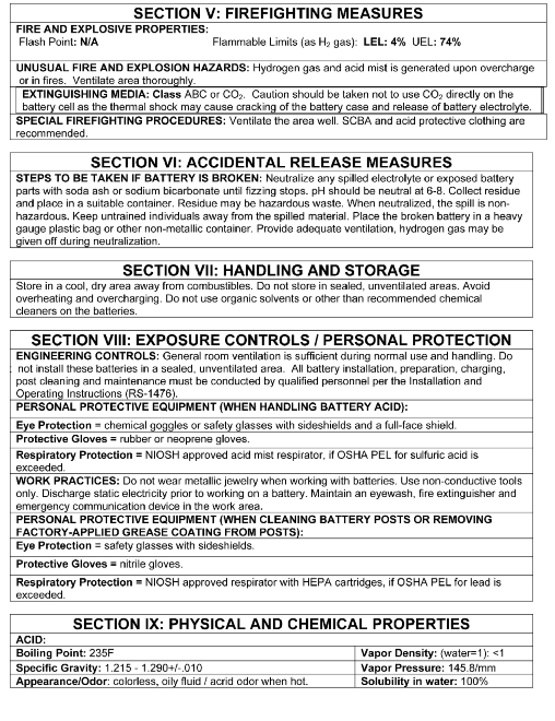
37

38
39 APPENDIXB-mAtErIAlsAfEtyDAtAshEEt
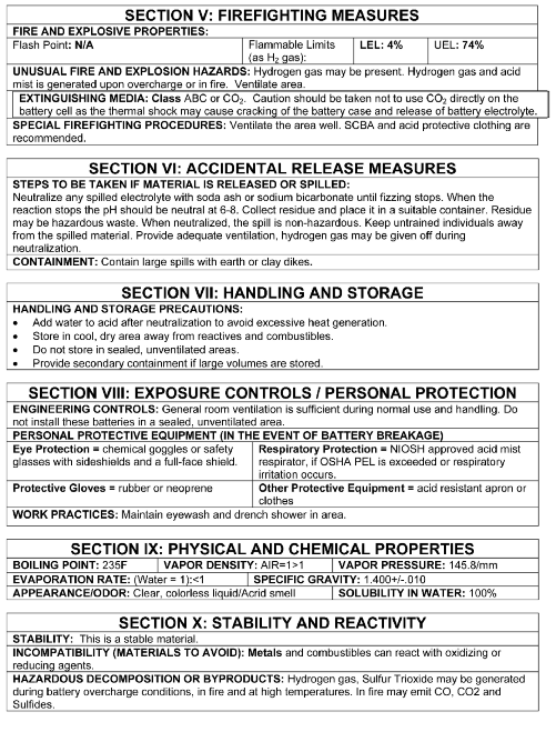
40

41
42 Introduction: Spill Containment Systems are used to contain and absorb/neutralize the release of battery electrolyte from damaged lead acid batteries used in stationary applications. Spill Containment Systems are designed with the minimal number of components for ease of installation and overall simplicity. Components may vary from supplier to supplier, yet all systems produce the same results. Components include a 4" high barrier that is typically bolted to the floor with sealed seams and joints. The floor can either be coated with an epoxy paint or have a protective liner. The barriers and the floor must create a watertight area and must be impervious to the liquid being stored. The final component is the pillows, which can absorb or neutralize and absorb the battery electrolyte. C&D only provides neutralizing and absorbing pillows. All components have an flame retardant rating. Compliance: Spill Containment Systems are required to comply with various codes used for building safety when stationary lead acid batteries systems have been installed. The decision to use Spill Containment Systems is based on local, regional, state or national codes as directed by the authority having jurisdiction (AHJ). C&D does not decide or require the use of Spill Containment Systems for our customers. However, C&D recommends the use of any methods and products that assure building and battery room safety for our customers. Spill Containment Systems Suppliers: Spill Containment Systems offered by C&D with or without our Stationary Batteries are designed to meet or exceed all requirements and specifications set forth by all applicable codes pertaining to Stationary Lead-Acid batteries and Battery Room Safety. Our suppliers warrant these products and copies are available with Spill Containment Systems. C&D will provide information on the available Spill Containment Systems including any specifications or third party testing and verification if requested. Selection: C&D has determined which Spill Containment Systems will fit our existing Battery Racks. Additionally, custom sizes are available with exact dimensions or room layouts. For proper compliance, the inside of the barrier area must have a 1" perimeter around the shadow area of the Battery Rack. Installation: APPENDIX C - SPILL CONTAINMENT FIGURE C.1 - Spill Containment Barriers with Pillows Provided with the Spill Containment System are instructions for proper installation with diagrams and a bill of materials or packing list. In most cases, the installation of Spill Containment Systems should be made prior to the installation of the Battery Rack. If a Spill Containment Systems is to be installed after the installation of the battery rack, please consult with your C&D rep to determine which Spill Containment System will be best for this situation. 40
43 1400 UNION MEETING ROAD BLUE BELL, PA Inspected By: Inspected Date: STATIONARY BATTERIES AND CHARGERS INSPECTION REPORT User: Battery Location: Contact: Phone No: Other: OEM: Installed By: BATTERY INFORMATION USER INSPECTION C&D Order No. Date Mfg. Date Installed Model Cells x Strings Application Electrolyte Level Bus Volts, Portable Meter Bus Volts, Panel, Final Top Tier, Cells Mid Tier, Cells Bottom Tier, Cells Charger Cap & Type C&D INSPECTION Appearance of Following: Pos. Post Pos. Strap Pos. Plate Neg. Post Neg. Strap Neg. Plate Cover rise, (eighths of an inch) Jar Bulge, (eighths of an inch) Jar Cracks Sediment Amount Sediment Appearance Lubricant observed on rack rails or bottom of cell containers: Serial No. Or WO yes no Room Ambient Temp. Watering Interval Last Discharge Peak Load Typical Load COMMENTS AND RECOMMENDATIONS Form RS 105-Rev
44 Required Maintenance Documents for Warranty BATTERY STATUS OPEN CIRCUIT FLOAT EQUALIZE Office: Model: Date: Cell Volts Temp. Sp.Gr. Serial or Cell Volts Temp. Sp.Gr. Serial or No Deg. F Work Order No. No Deg. F Work Order No. Add measure and record string charge current (amps) after 96 and 100 hours equalization or 68 and 72 hours float..
45 1400 Union Meeting Road P.O. Box 3053 Blue Bell, PA (215) Fax (215) (800) Any data, descriptions or specifications presented herein are subject to revision by C&D Technologies, Inc. without notice. While such information is believed to be accurate as indicated herein, C&D Technologies, Inc. makes no warranty and hereby disclaims all warranties, express or implied, with regard to the accuracy or completeness of such information. Further, because the product(s) featured herein may be used under conditions beyond its control, C&D Technologies, Inc. hereby disclaims all warranties, either express or implied, concerning the fitness or suitability of such product(s) for any particular use or in any specific application or arising from any course of dealing or usage of trade. The user is solely responsible for determining the suitability of the product(s) featured herein for user s intended purpose and in user s specific application. Copyright 2010 C&D TECHNOLOGIES, INC. Printed in U.S.A. RS /CD
ATS Overhead Table Shelf System INSTRUCTION MANUAL
 ATS Overhead Table Shelf System INSTRUCTION MANUAL ATS Overhead Table Shelf System Instruction Manual Warranty Newport Corporation warrants this product to be free of defects in material and workmanship
Installation and Operating Instructions (for chargers shown below)
") Installation and Operating Instructions (for chargers shown below) For additional information please call our Technical Support Group 800.742.2740 PRO CHARGING SYSTEMS, LLC 1551 Heil Quaker Boulevard,
Installation and Operating Instructions (for chargers shown below) For additional information please call our Technical Support Group 800.742.2740 PRO CHARGING SYSTEMS, LLC 1551 Heil Quaker Boulevard,
OASIS-PLUS 120V READ ALL INSTRUCTIONS BEFORE OPERATING READ ALL INSTRUCTIONS BEFORE OPERATING OZONE IS A POWERFUL OXIDIZER AND MUST BE USED WITH CARE
 OASIS-PLUS 120V INFORMATION & OPERATING INSTRUCTIONS READ ALL INSTRUCTIONS BEFORE OPERATING READ ALL INSTRUCTIONS BEFORE OPERATING OZONE IS A POWERFUL OXIDIZER AND MUST BE USED WITH CARE 56041852 WARNING:
Substation Battery & Charger Maintenance
 Document title AUTHORIZED COPY Substation Battery & Charger Maintenance Document number MNT-TRMX-00015 Applies to: Keywords: Transmission Operations & Planning Department Carolinas and Florida maintenance;
Height w/o Terminals (in)
") EaglePicher Technologies, LLC Commercial Power P.O. Box 47 Joplin, MO 6482 (417) 623-8 [email protected] Carefree Sealed Lead Acid (SLA) MSDS EaglePicher s Carefree lead acid batteries are
EaglePicher Technologies, LLC Commercial Power P.O. Box 47 Joplin, MO 6482 (417) 623-8 [email protected] Carefree Sealed Lead Acid (SLA) MSDS EaglePicher s Carefree lead acid batteries are
10 Year VRLA Battery Periodic Maintenance Instructions
 TECHNICAL BULLETIN 41-7546 Valve Regulated Lead Acid Battery 20 to 200 ampere-hours capacity 10 Year VRLA Battery Periodic Maintenance Instructions 41-7546/0213/CD www.cdtechno.com General Information
IMPORTANT INSTRUCTIONS & OPERATING MANUAL. Houston 50 Inch Electric Wall Mounted Fireplace Black / White
 IMPORTANT INSTRUCTIONS & OPERATING MANUAL Houston 50 Inch Electric Wall Mounted Fireplace Black / White Model Number:MFE5050BK Model Number:MFE5050WH Read these instructions carefully before attempting
Installation and Operating Instructions (for chargers shown below)
") Installation and Operating Instructions (for chargers shown below) For additional information please call our Technical Support Group 800.742.2740 PRO CHARGING SYSTEMS, LLC 1551 Heil Quaker Boulevard,
Installation and Operating Instructions (for chargers shown below) For additional information please call our Technical Support Group 800.742.2740 PRO CHARGING SYSTEMS, LLC 1551 Heil Quaker Boulevard,
ARCO Electric Products Installation and Maintenance Manual Low Voltage Automatic Power Factor Correction Capacitor Systems 2013
 ARCO Electric Products Installation and Maintenance Manual Low Voltage Automatic Power Factor Correction Capacitor Systems 2013 READ CAREFULLY These instructions are intended to cover good practices in
FLOODED BATTERY RACKS SELECTION GUIDE FOR RDB & RDC SERIES, STANDBY POwER RACKS
 12-560 FLOODED BATTERY RACKS SELECTION GUIDE FOR RDB & RDC SERIES, STANDBY POwER RACKS Non-seismic and Earthquake Protected (EP1, EP2), IEEE-693,,, D, DJ, DJU, J, K, and L/XT Cell Types Heavy Gauge Steel
BC-5000 OPERATIONS MANUAL BATTERY CAPACITY TESTER COFKO LLC.
 BC-5000 BATTERY CAPACITY TESTER OPERATIONS MANUAL COFKO LLC. COPYRIGHT 2010 1 UNPACKING As you unpack your new BC-5000 battery capacity tester, inspect the tester for signs of shipping damage. If shipping
SEWER CHEWER Wastewater / Sludge Grinder Submersible Gearmotor
 INSTALLATION, OPERATION AND MAINTENANCE MANUAL For SEWER CHEWER Wastewater / Sludge Grinder Submersible Gearmotor Yeomans Chicago Corporation 3905 Enterprise Court P.O. Box 6620 Aurora, IL 60598-0620 Phone:
If you accidentally get battery acid on your skin, flush it with lots of water
 RV Battery Savvy To properly maintain and extend the life of your RV batteries you need to have a basic understanding of what a battery is and how it works. Batteries used in RVs are lead acid batteries.
Packaged Terminal Air Conditioner Wall Sleeve Installation
 Installation & Maintenance Data IM 1196 Group: PTAC Part Number: 910141799 Date: October 2013 Packaged Terminal Air Conditioner Installation x 42" PGAN with Top-Mounted Hydronic Heat Note: Installation
Select Radiators Installation Guide
 Select Radiators Installation Guide Table of Contents Informational Symbols...3 Before You Begin...4 Select Rough-In... 5 Connection Installation...6 Optional Piping Arrangements...7 Conventional Wall
MISSION CRITICAL FACILITIES DESIGN UPS BATTERY ROOM ENVIRONMENT CRITICAL DESIGN CONSIDERATIONS
 MISSION CRITICAL FACILITIES DESIGN UPS BATTERY ROOM ENVIRONMENT CRITICAL DESIGN CONSIDERATIONS Allen Wood Vice President Data Center Division Engineering Design Group INTRODUCTION It can be very effectively
Installation Instructions for Alarm Module Kit A043F059
 Instruction Sheet 07-2013 Installation Instructions for Alarm Module Kit A043F059 1 Introduction The information contained within is based on information available at the time of going to print. In line
BATTERY CHARGING GUIDELINES FOR 6-VOLT DEEP CYCLE BATTERIES
 BATTERY CHARGING GUIDELINES FOR 6-VOLT DEEP CYCLE BATTERIES Introduction Your 6-volt deep cycle battery set has been specially formulated for long cycle life and has particular voltage and specific gravity
LEAD CRYSTAL. User Manual. Valve-regulated lead-crystal batteries Energy storage Cells
 Engineering Production Sales LEAD CRYSTAL Valve-regulated lead-crystal batteries Energy storage Cells User Manual www.axcom-battery-technology.de [email protected] Chapter 1: 1. Introduction
SOLAR PV SYSTEM MAINTENANCE GUIDE
 SOLAR PV SYSTEM MAINTENANCE GUIDE GUYANA HINTERLANDS STAND-ALONE SOLAR PV INSTALLATIONS IMPROVING HEALTH FACILITY INFRASTRUCTURE (IHFI) GUYANA CONTRACT NO. EPP-I-00-03-00008-00, TASK ORDER 07 APRIL 2013
BATTERY BASICS. This Automotive Series 12-volt Lead Acid BATTERY BASICS has been developed by. Kevin R. Sullivan
 BATTERY BASICS This Automotive Series 12-volt Lead Acid BATTERY BASICS has been developed by Kevin R. Sullivan Professor of Automotive Technology Skyline College All Rights Reserved v1.1 Visit us on the
Solar Wind Microhydro Water Pumping Inverters Batteries Professional system design and installation
 Solar Wind Microhydro Water Pumping Inverters Batteries Professional system design and installation BATTERY CHARGING GUIDELINES FOR GLOBAL/DAVIDSON TUBULAR PLATE BATTERIES Introduction Your Global/Davidson
12 Volt 30 Amp Digital Solar Charge Controller
 12 Volt 30 Amp Digital Solar Charge Controller User s Manual WARNING Read carefully and understand all INSTRUCTIONS before operating. Failure to follow the safety rules and other basic safety precautions
NorthStar Battery (NSB) Telecom Installation and Operation Guide
 Telecom Installation and Operation Guide") 15DOC0020 NorthStar Battery (NSB) Telecom Installation and Operation Guide Contents 0 Definitions... 3 1 Battery Safety... 3 1.1 Old Batteries... 3 2 Handling... 4 2.1 Receiving the shipment... 4 2.2 Do...
15DOC0020 NorthStar Battery (NSB) Telecom Installation and Operation Guide Contents 0 Definitions... 3 1 Battery Safety... 3 1.1 Old Batteries... 3 2 Handling... 4 2.1 Receiving the shipment... 4 2.2 Do...
HP UPS R1500 Generation 3
 HP UPS R1500 Generation 3 Installation Instructions Part Number 650952-001 NOTE: The rating label on the device provides the class (A or B) of the equipment. Class B devices have a Federal Communications
TELEDYNE BATTERY PRODUCTS. INSTRUCTIONS FOR CONTINUED AIRWORTHINESS and COMPONENT MAINTENANCE MANUAL. For
 TELEDYNE BATTERY PRODUCTS INSTRUCTIONS FOR CONTINUED AIRWORTHINESS and COMPONENT MAINTENANCE MANUAL For TSO-C173/C173a Authorized (GILL ) 7000 Series LT Valve-Regulated Lead-Acid Aircraft Batteries REFER
Uninterruptible Power Supply. 500 kva - 750 kva
 9 315 Uninterruptible Power Supply 500 kva - 750 kva T1 and T3 Installation Addendum 164201244-001 Rev. A ------------------------------------------------------------------------ ------------------------------------------------------------------------
D. Infrared scanning reports with pictures printed in a final report with any deficiencies and actions taken to rectify.
 SECTION 263354 STATIC UPS TESTING AND COMMISSIONING PART 1 - GENERAL 1.1 SUMMARY A. Section Includes 1. System start-up services. 2. Battery charging. 3. Load bank testing. 4. Battery load testing. 5.
Amps Per Bank. Total Output. Battery System. Model Name. 6 amps 12 amps 10 amps 20 amps 30 amps 40 amps 15 amps 30 amps 45 amps
 Model Name Total Output Amps Per Bank Battery System Pro XL Dual Pro XL Pro SE Dual Pro SE Three Bank Pro SE Four Bank Pro SE Pro Charger Dual Pro Charger Three Bank Pro Charger 6 amps 12 amps 10 amps
Height w/o Terminals (in)
") EaglePicher Technologies, LLC Commercial Power P.O. Box 47 Joplin, MO 6482 (417) 623-8 [email protected] Carefree Sealed Lead Acid (SLA) MSDS EaglePicher s Carefree lead acid batteries are
EaglePicher Technologies, LLC Commercial Power P.O. Box 47 Joplin, MO 6482 (417) 623-8 [email protected] Carefree Sealed Lead Acid (SLA) MSDS EaglePicher s Carefree lead acid batteries are
FOR THE FOLLOWING MODELS: EE-8075W EE-8075O EE-8075R EE-8075BK
 FIREPLACE HEATER FOR THE FOLLOWING MODELS: EE-8075W EE-8075O EE-8075R EE-8075BK If you have any questions about the operation of your fireplace heater, please contact Crane Customer Care. Toll Free: 888-599-0992
SOLAR ELECTRIC MODULE ES-124 & ES-62T Owners Manual and Installation Guide
 SOLAR ELECTRIC MODULE ES-124 & ES-62T Owners Manual and Installation Guide circuit. Reverse connection will damage the module and may result in fire. CAUTIONS Solar electric modules produce DC electricity
AUTOMATIC BEST BATTERY SELECTOR INSTALLATION & OPERATION BBS-1600 BBS-1600E
 AUTOMATIC BEST BATTERY SELECTOR INSTALLATION & OPERATION BBS-1600 BBS-1600E SENS part no: 101314 Document revision: F DCN No. 106811 Date 8/3/15 1840 Industrial Circle Longmont, CO 80501 Fax: (303) 678-7504
12-Volt Negative Ground Installation Instructions
 12-Volt Negative Ground Installation Instructions For Part Number: 1141, 1164, 1165, 1181 CAUTION!!! Before installing, please read the following important information... 1. The Ignitor is designed for
3. SEISCO PARTS & SERVICE REMOVAL AND REPAIR GUIDE
 4 3. SEISCO PARTS & SERVICE REMOVAL AND REPAIR GUIDE A. Changing the Control Board B. Replacing a Heating Element C. Thermistor Replacement D. High Limit Switch Replacement E. Level Detector Replacement
3 WATT LED SPOTLIGHT Model No. SLM - 3801
 3 WATT LED SPOTLIGHT Model No. SLM - 3801 OWNER'S MANUAL Customer Service Tel: 1-800-268-3319 Superex Canada Ltd, Toronto,M2H 3B8 Made in China Table of Contents A). Important Safety Instructions B). Charging
CHARGING SYSTEMS INTERNATIONAL
 CHARGING SYSTEMS INTERNATIONAL INSTALLATION AND OPERATING INSTRUCTIONS FOR THE FOLLOWING BATTERY CHARGING SYSTEMS: MODELS MAX AMPS/BANK NO. OF BANKS BATTERY SYSTEM PRO XL 6 1 12 DUAL PRO XL 6 2 12/24 PRO
6 & 12 Volt Battery and Systems Tester with 100 Amp Load
 6 & 12 Volt Battery and Systems Tester with 100 Amp Load Form No. 841-731 -000 DESCRIPTION This Load Tester tests 6 or 12 volt automotive-size lead-acid batteries under load. It will also test 6 or 12
Use & Care. of your Iron. All about the TA B L E O F C O N T E N T S. USA and Canada 1-888-845-7330
 All about the Use & Care of your Iron Important Safeguards... 2 Iron Safety Instructions... 3 Parts and Features...4 TA B L E O F C O N T E N T S Using Your Iron...6 Cleaning and Maintenance... 8 Warranty...9
BATTERY SERVICE. This Automotive Series BATTERY SERVICE has been developed by. Kevin R. Sullivan. Professor of Automotive Technology Skyline College
 BATTERY SERVICE This Automotive Series BATTERY SERVICE has been developed by Kevin R. Sullivan Professor of Automotive Technology Skyline College All Rights Reserved v1.1 Visit us on the web at: www.autoshop101.com
Electric Fryers Instruction Manual Models: 8047D, 8048D, 8049D, 8050D, 8051D 8066, 8068, 8068FL, 8073, 8073BF and 8075
 Part No. 89047 Electric Fryers Instruction Manual Models: 8047D, 8048D, 8049D, 8050D, 8051D 8066, 8068, 8068FL, 8073, 8073BF and 8075 Cincinnati, OH 45241-4807 USA ELECTRIC FRYER SAFETY PRECAUTIONS Installation
Instruction Manual. Window Wiper AFW900. (Read carefully before use)
") Instruction Manual Window Wiper AFW900 (Read carefully before use) When using electrical appliances, basic precautions should always be followed, including the fact READ ALL INSTRUCTIONS IN THIS MANUAL
Instruction Manual Window Wiper AFW900 (Read carefully before use) When using electrical appliances, basic precautions should always be followed, including the fact READ ALL INSTRUCTIONS IN THIS MANUAL
EPSOLAR LS0512R / LS0524R. Solar Light Controller INSTRUCTION MANUAL. Please read this manual carefully before using the product!
 EPSOLAR LS0512R / LS0524R Solar Light Controller INSTRUCTION MANUAL Please read this manual carefully before using the product! LandStar LS0512R / LS0524R Solar Light Controller Nominal system voltage
GENERAL INSTALLATION MANUAL FOR EGING PV MODULES
 GENERAL INSTALLATION MANUAL FOR EGING PV MODULES PLEASE READ THIS MANUAL CAREFULLY BEFORE INSTALLING OR USING THE MODULES. PLEASE PASS ALONG THE ATTACHED USER MANUAL TO YOUR CUSTOMER. 1. INTRODUCTION This
Safety and Installation Instructions for AC Modules
 Safety and Installation Instructions for AC Modules United States and Canada Contents of this manual are subject to change without notice. For the latest guide please refer to www.sunpower.com/pvinstallguideacmodule
Owner s Guide and Installation Manual. Vancouver Model Name. 21321, 21328 Model No. English Español
 For Your Records and Warranty Assistance For reference, also attach your receipt or a copy of your receipt to the manual. Vancouver Model Name 21321, 21328 Model No. Type A Models Owner s Guide and Installation
12 Volt 30 Amp Digital Solar Charge Controller Installation & Operation Manual
 12 Volt 30 Amp Digital Solar Charge Controller Installation & Operation Manual This 30Amp charge controller is designed to protect your 12Volt Lead-acid or Gel-cell battery from being overcharge by solar
758 Heavy-duty Ratchet Guy Wire Cutter
 INSTRUCTION MANUAL 758 Heavy-duty Ratchet Guy Wire Cutter Read and understand all of the instructions and safety information in this manual before operating or servicing this tool. Register this product
LS1024B / LS2024B/ LS3024B. Solar Charge Controller USER MANUAL
 EPSOLAR LS1024B / LS2024B/ LS3024B Solar Charge Controller USER MANUAL Thank you very much for selecting our product! This manual offers important information and suggestions with respect to installation,
DiscPlus DX195 and DX225 Air Disc Brakes
 Revised 11-04 Technical Bulletin Revised 1 Technical 11-04 Bulletin DiscPlus DX195 and DX225 Air Disc Brakes Inspection, Installation and Diagnostics Air Disc Brake Inspection Intervals and Procedures
Capacity Testing of VRLA Batteries (20 to 200 Ampere-Hours Capacity)
") TECHNICAL BULLETIN 41-7135 Capacity Testing of VRLA Batteries (20 to 200 Ampere-Hours Capacity) 41-7135/0412/CD www.cdtechno.com The VRLA battery is rated in ampere-hours or watts per cell (w/c) at specific
TECHNICAL BULLETIN 41-7135 Capacity Testing of VRLA Batteries (20 to 200 Ampere-Hours Capacity) 41-7135/0412/CD www.cdtechno.com The VRLA battery is rated in ampere-hours or watts per cell (w/c) at specific
TROJAN BATTERY USER S GUIDE
 Congratulations on your purchase from Trojan Battery Company, the manufacturer of the world s most trusted deep cycle batteries. The battery you purchased was engineered by Trojan to deliver superior power,
CAST IRON THE BASICS. Heatline - Cast Iron Radiators SMOOTH FLAT FILE TO REMOVE ANY SWARF. ONE TIME. ASSEMBLY. JOINTS SHOULD BE TIGHTENED.
 CAST IRON THE BASICS 1. DO NOT LIFT ON YOUR OWN. 2. ONLY LIFT THE RADIATOR VERTICALLY. 3. DO NOT LIFT MORE THAN 8/10 SECTIONS AT ANY ONE TIME. 4. POSITION THE RADIATOR BEFORE FINAL ASSEMBLY. 5. THIS PRODUCT
Carefree Sealed Lead Acid (SLA) MSDS
 MSDS") EaglePicher Technologies, LLC Commercial Power P.O. Box 47 Joplin, MO 6482 (417) 623-8 [email protected] Carefree Sealed Lead Acid (SLA) MSDS EaglePicher s Carefree lead acid batteries are
EaglePicher Technologies, LLC Commercial Power P.O. Box 47 Joplin, MO 6482 (417) 623-8 [email protected] Carefree Sealed Lead Acid (SLA) MSDS EaglePicher s Carefree lead acid batteries are
Guidelines for Earthquake Bracing of Residential Water Heaters
 Guidelines for Earthquake Bracing of Residential Water Heaters Department of General Services Division of the State Architect 1102 Q Street, Suite 5100 Sacramento, CA 95814 Phone: (916) 324-7099 Fax: (916)
Set-Up Instructions. (Liner-Based System) UL LISTED. Important Read set-up instructions before assembly. Report any shortages within 72 hours
 UL LISTED. Important Read set-up instructions before assembly. Report any shortages within 72 hours") INDUSTRIAL POWER Set-Up Instructions (Liner-Based System) UL LISTED Important Read set-up instructions before assembly. Report any shortages within 72 hours Specializing in Environmental and Fire-Life
INDUSTRIAL POWER Set-Up Instructions (Liner-Based System) UL LISTED Important Read set-up instructions before assembly. Report any shortages within 72 hours Specializing in Environmental and Fire-Life
3620 W 11th Streetб Houston, TX 77008 Telephone: 713-635-6291 Email: [email protected] Website: www.kellogg-american.com
 Unpackaging & Handling Be sure to carefully inspect the unit before accepting the shipment. If any damage has occurred document it with the trucking company immediately. Contact your Kellogg Distributor
I BEAM TRACK INSTALLATION
 PDQ 0/700 FESTOON SYSTEM INSTALLATION AND MAINTENANCE INSTRUCTIONS INTRODUCTION The PDQ Festoon System was designed to run on one of three sizes of I-beams: S x., S8 x 8. and S x.. System trolleys must
About the BitStorm 6051 POTS Splitter
 BitStorm 6051 Installation Instructions Document Number 6051-A2-GZ40-10 July 2002 About the BitStorm 6051 The BitStorm system enables simultaneous high-speed digital data access and analog voice service
Replacement of 600-Ampere Bushing and 200-Ampere Bushing-Well Adapters
 S&C Vista SD Underground Distribution Switchgear Pad-Mounted and Vault-Mounted Style Outdoor Distribution (17.5 kv and 29 kv) With Visi-Gap Load Interrupter Switches and Visi-Gap Fault Inetrrupters Replacement
ALL WEATHER W-SERIES QUARTZ TUBE ELECTRIC INFRARED RADIANT HEATER INSTALLATION USE & CARE MANUAL
 ALL WEATHER W-SERIES QUARTZ TUBE ELECTRIC INFRARED RADIANT HEATER TABLE OF CONTENTS: INSTALLATION USE & CARE MANUAL IMPORTANT INFORMATION Assembly Instructions 2 Wiring Instructions 2 Outdoor Installation
Coolflo Safe Touch Shower Mixing Valve ST20015CP
 Coolflo Safe Touch Shower Mixing Valve ST20015CP Installation and Maintenance Instructions In this procedure document we have endeavoured to make the information as accurate as possible. We cannot accept
INSTALLATION AND OPERATING INSTRUCTIONS For Model GL1 Gate Locks
 Securitron Magnalock Corp. www.securitron.com ASSA ABLOY, the global leader Tel 800.624.5625 [email protected] in door opening solutions INSTALLATION AND OPERATING INSTRUCTIONS For Model GL1 Gate
Digital echo-charge. Owner s Manual. Xantrex Digital echo-charge Battery Charger
 Digital echo-charge Owner s Manual Xantrex Digital echo-charge Battery Charger Thank you for purchasing a Xantrex Digital echo-charge. Xantrex Technology Inc. takes pride in manufacturing quality products
INSPECTION, MAINTENANCE AND RECHARGE SERVICE MANUAL P/N 16303
 WATER MIST HAND PORTABLE FIRE EXTINGUISHERS Model B270 ¾ Gallon Model B272 2 ½ Gallon INSPECTION, MAINTENANCE AND RECHARGE SERVICE MANUAL P/N 6303 All fire extinguishers should be installed, inspected
4RU High Density Shelf Installation Instructions
 4RU High Density Shelf Installation Instructions Table of Contents General Product Information... 1.0 Safety Precautions... 2.0 Tools Required... 3.0 Package Contents... 4.0 Installing the Product Unpacking...
Battery Backup Sump Pump System
 Instruction Manual & Safety Warnings Table of Contents Important Safety Warnings and Instructions Electrical precautions 1 Battery preparation 1 Battery precautions 1 Introduction Items included in system
Cooktop Low-Profile Ventilation Hoods
 INSTALLATION GUIDE Cooktop Low-Profile Ventilation Hoods Contents Wolf Cooktop Low-Profile Ventilation Hoods........ 3 Cooktop Low-Profile Hood Specifications.......... 4 Cooktop Low-Profile Hood Installation............
Series 30000 Hose Reels
 Operating Instructions and Parts List for Series 30000 Hose Reels - MANUAL DRIVEN - - POWER DRIVEN - SAFETY PRECAUTIONS Personal injury and/or equipment damage may result if proper safety precautions are
IMPORTANT SAFETY RULES TO FOLLOW
 WARNING FLOOR & CARPET CLEANER Any piece of equipment can be dangerous if not operated properly. YOU are responsible for the safe operation of this equipment. The operator must carefully read and follow
GreenWay Solar LED Path and Trail Lighting System. Installation and Owner s Manual
 GreenWay Solar LED Path and Trail Lighting System Installation and Owner s Manual Important Notes and Warnings This installation and instruction manual provides installation, operation, and maintenance
Active and Passive Sash Replacement
 for Andersen Gliding Windows Read all instructions carefully before attempting this procedure. If you have any questions about your ability to complete the procedure, call Andersen at 1-888-888-7020 for
RAY-MAX Integrated Solar Power Strip
 RAY-MAX Integrated Solar Power Strip 600008, 600009, 600010, 600208, 600209, 600210 Owner s Manual NEXTRONEX, INC. Revision Date: 10/27/14 Contents 1. Safety Instructions... 3 2. General Equipment Warnings...
EXCERPT - THE DATA CENTER BATTERY DILEMMA
 Consulting Associates, Inc. Page 1 EXCERPT - THE DATA CENTER BATTERY DILEMMA Developed by Marco W. Migliaro, PE, Life Fellow IEEE Visit: stationarybatterytraining.com esaconsulting.com Copyright 2014 by
MGB Chrome Bumper Conversion
 MGB Chrome Bumper Conversion Installation Instructions For 1974 1/2-1980 MGB This kit requires cutting, welding, and painting. Professional installation recommended. Note: Every MGB body is slightly different
OWNER S MANUAL FORCE 10 MARINE COMPANY 23080 HAMILTON ROAD RICHMOND, BC CANADA V6V 1C9 TEL: (604) 522-0233 FAX: (604) 522-9608
 522-0233 FAX: (604) 522-9608") Electric Water Heater OWNER S MANUAL FORCE 10 MARINE COMPANY 23080 HAMILTON ROAD RICHMOND, BC CANADA V6V 1C9 TEL: (604) 522-0233 FAX: (604) 522-9608 If your water Heater is Damaged or you have questions
Electric Water Heater OWNER S MANUAL FORCE 10 MARINE COMPANY 23080 HAMILTON ROAD RICHMOND, BC CANADA V6V 1C9 TEL: (604) 522-0233 FAX: (604) 522-9608 If your water Heater is Damaged or you have questions
Turbocharger system components, servicing
 21-1 Turbocharger system components, servicing Engine codes: AAZ, 1Z, AHU Observe rules of cleanliness Page 21-10 Turbocharger hoses and lines, connecting Page 21-11 WARNING! Do not re-use any fasteners
The table below lists the symbols used on the Clamp and/or in this manual. Important Information. See manual.
 i800 AC Current Clamp Instruction Sheet Introduction The i800 AC Current Clamp, the Clamp, has been designed for use with multimeters, recorders, power analyzers, safety testers, etc., for accurate non-intrusive
PowerFlex 700S and 700H Frame 12 DC Bus Connector Kit
 PowerFlex 700S and 700H Frame 12 DC Bus Connector Kit Installation Instructions This document provides instructions for the installation of a DC bus connector kit for PowerFlex 700S and 700H frame 12 drives
METHOD STATEMENT INSTALLATION OF INSULATING FLANGE KITS
 METHOD STATEMENT INSTALLATION OF INSULATING FLANGE KITS Revision Date Prepared By Approved By Method Statement IF Kits BAC Corrosion Control Limited Stafford Park 11 Telford TF3 3AY Tel: 01952 290321 Fax:
About this Manual. Support for Your Product
 About this Manual We ve added this manual to the Agilent website in an effort to help you support your product. This manual is the best copy we could find; it may be incomplete or contain dated information.
BRAKE DRUM AND ROTOR SERVICE INFORMATION
 SERVICE INFORMATION To achieve maximum drum life and optimum performance, proper brake maintenance and brake balance are essential. Consult your truck or trailer manufacturer s maintenance manual for proper
Spec. No. ICR18650-26C Version No. 0.0
 1. Scope This product specification has been prepared to specify the rechargeable lithium-ion cell 2. Description and Model 2.1 Description Cell (lithium-ion rechargeable cell) 2.2 Model ICR18650-26C 3.
4 in 1 Strength Station
 Revision 0 September 2010 4 in 1 Strength Station Owner s Manual Record Serial Number Here Platinum by Tunturi www.tunturi.com Date www.tunturi.com of Purchase 4 in 1 Strength Station Owner s Manual Instructions
Co-location Interconnect Power Panel (CIPP) Installation Guide
 Installation Guide") Co-location Interconnect Power Panel (CIPP) Installation Guide Document INS-97xxxxxxx This guide covers the following part numbers- Trimm 97xxxxxxx Series Table of Contents Section 1 - General Information...
Co-location Interconnect Power Panel (CIPP) Installation Guide Document INS-97xxxxxxx This guide covers the following part numbers- Trimm 97xxxxxxx Series Table of Contents Section 1 - General Information...
Installation Instructions for FT-10 Network PowerCommand ATS Communication Module (NCM) Kits 541 0812 and 541 0868
 Kits 541 0812 and 541 0868") Instruction Sheet 10-2004 Installation Instructions for FT-10 Network PowerCommand ATS Communication Module (NCM) Kits 541 0812 and 541 0868 PowerCommand is a registered trademark of Cummins Inc. InPower
Instruction Sheet 10-2004 Installation Instructions for FT-10 Network PowerCommand ATS Communication Module (NCM) Kits 541 0812 and 541 0868 PowerCommand is a registered trademark of Cummins Inc. InPower
Mobile Data Power Model: MDP-25
 Mobile Data Power Model: MDP-25 Topic Section Features... 2 Operational Features Summary... 2 Back-up Battery Power Internal Charger Voltage Spike Protection RF Noise Filtering Warning of Imminent Loss
INSTRUCTION MANUAL IM042. Slide Rail Systems - Series A10 INSTALLATION, OPERATION AND MAINTENANCE INSTRUCTIONS
 INSTRUCTION MANUAL IM042 Slide Rail Systems - Series A10 INSTALLATION, OPERATION AND MAINTENANCE INSTRUCTIONS TABLE OF CONTENTS SUBJECT PAGE Safety Instructions... 3 Descriptions and Specifications...
M113 VEHICLE FAMILY RUBBER TRACK INSTALLATION INSTRUCTIONS SOUCY TRACK SYSTEM 04-M113-1ENS (SPLIT IDLER) Litho d in Canada 1 04-M113-1ENS
 Litho d in Canada 1 04-M113-1ENS") M113 VEHICLE FAMILY RUBBER TRACK INSTALLATION INSTRUCTIONS (SPLIT IDLER) 1 # TABLE OF CONTENTS List of parts and tools................................................3 Installation of complete kit...................................................5
M113 VEHICLE FAMILY RUBBER TRACK INSTALLATION INSTRUCTIONS (SPLIT IDLER) 1 # TABLE OF CONTENTS List of parts and tools................................................3 Installation of complete kit...................................................5
Installation and Operation Guide for PD4000 Series Power Control Center
 Extended warranties are available for purchase at www.progressivedyn.com Installation and Operation Guide for PD4000 Series Power Control Center Member Thank you for selecting Progressive Dynamics as your
TWIN EAGLES ALL WEATHER ELECTRIC RADIANT HEATER
 TWIN EAGLES, INC. Defining the Art of Outdoor Cooking TWIN EAGLES ALL WEATHER ELECTRIC RADIANT HEATER OWNER S MANUAL MODEL TEEH-1512 TEEH-2524 TEEH-3524 NEED ASSISTANCE? PLEASE CALL: (562) 802-3488 This
Agilent X/P/K281C Adapters
 Agilent X/P/K281C Adapters Including Options 006, 012, 013, 106 Operating and Service Manual Contents 1 Introduction 7 Product Overview 8 Options 8 Instruments Covered by Manual 10 2 Installation 11 Initial
Global Water Instrumentation, Inc.
 Global Water Instrumentation, Inc. 11390 Amalgam Way Gold River, CA 95670 T: 800-876-1172 Int l: (916) 638-3429, F: (916) 638-3270 Solar Panels 2 Watt Solar Panel: SP101 5 Watt Solar Panel: SP102 01-752
Ducoterra Radiant Heating Panel Installation Manual
 Ducoterra Radiant Heating Panel Installation Manual 1. Introduction Your new radiant heating panels are designed to heat living and working spaces rapidly and efficiently by radiant heating. Like the sun,
TECHNICAL ASSISTANCE TOLL FREE TELEPHONE NUMBER 1.800.591.9360 TECHNICAL ASSISTANCE FAX: 1.626.855.4894
 ACORN SAFETY P.O. BOX 3527 CITY OF INDUSTRY, CA 9744-0527 UNITED STATES OF AMERICA WWW.ACORNSAFETY.COM INSTALLATION, OPERATION AND MAINTENANCE INSTRUCTIONS FREEZE RESISTANT WALL MOUNTED EMERGENCY EYEWASH
Name of Equipment Silver King Model SKMCD1P/C1. This equipment chapter is to be inserted in the appropriate section of the Equipment Manual.
 Name of Equipment Silver King Model SKMCD1P/C1 This equipment chapter is to be inserted in the appropriate section of the Equipment Manual. Manufactured exclusively for McDonald s By Silver King Refrigeration,
Dehumidifier Users manual. For Models: DH45S DH65S
 Dehumidifier Users manual For Models: DH45S DH65S 950-0062-revD Jan. 9 2007 FORWARD The appearance of the units that you purchase might be slightly different from the ones described in the Manual, but
CEILING CASSETTE FAN COIL UNIT
 CEILING CASSETTE FAN COIL UNIT Operation and Installation Manual MHCFC4W-04, 08, 12, 16 Four way ceiling cassette fan coil unit Please read this manual before using the fan coil unit. Installation and
SERVICE MANUAL RESIDENTIAL ELECTRIC AND LIGHT DUTY COMMERCIAL ELECTRIC WATER HEATERS. Troubleshooting Guide and Instructions for Service
 RESIDENTIAL ELECTRIC AND LIGHT DUTY COMMERCIAL ELECTRIC WATER HEATERS SERVICE MANUAL Troubleshooting Guide and Instructions for Service (To be performed ONLY by qualified service providers) Models Covered