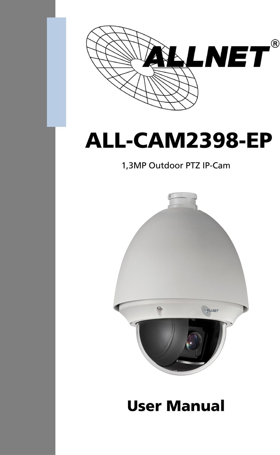
ALL-CAM2398-EP. 1,3MP Outdoor PTZ IP-Cam. User Manual
|
|
|
- June Norris
- 8 years ago
- Views:
Transcription
1 ALL-CAM2398-EP 1,3MP Outdoor PTZ IP-Cam User Manual
2 Default-IP via DHCP Username & Password: admin DISCLAIMER STATEMENT Underwriters Laboratories Inc. ( UL ) has not tested the performance or reliability of the security or signaling aspects of this product. UL has only tested for fire, shock or casualty hazards as outlined in UL s Standard(s) for Safety, UL UL Certification does not cover the performance or reliability of the security or signaling aspects of this product. UL MAKES NO REPRESENTATIONS, WARRANTIES OR CERTIFICATIONS WHATSOEVER REGARDING THE PERFORMANCE OR RELIABILITY OF ANY SECURITY OR SIGNALING RELATED FUNCTIONS OF THIS PRODUCT.

3 Regulatory Information FCC Information FCC compliance: This equipment has been tested and found to comply with the limits for a digital device, pursuant to part 15 of the FCC Rules. These limits are designed to provide reasonable protection against harmful interference when the equipment is operated in a commercial environment. This equipment generates, uses, and can radiate radio frequency energy and, if not installed and used in accordance with the instruction manual, may cause harmful interference to radio communications. Operation of this equipment in a residential area is likely to cause harmful interference in which case the user will be required to correct the interference at his own expense. FCC Conditions This device complies with part 15 of the FCC Rules. Operation is subject to the following two conditions: 1. This device may not cause harmful interference. 2. This device must accept any interference received, including interference that may cause undesired operation. EU Conformity Statement This product and - if applicable - the supplied accessories too are marked with "CE" and comply therefore with the applicable harmonized European standards listed under the Low Voltage Directive 2006/95/EC, the EMC Directive 2004/108/EC, the RoHS Directive 2011/65/EU. 2012/19/EU (WEEE directive): Products marked with this symbol cannot be disposed of as unsorted municipal waste in the European Union. For proper recycling, return this product to your local supplier upon the purchase of equivalent new equipment, or dispose of it at designated collection points. For more information see: /66/EC (battery directive): This product contains a battery that cannot be disposed of as unsorted municipal waste in the European Union. See the product documentation for specific battery information. The battery is marked with this symbol, which may include lettering to indicate cadmium (Cd), lead (Pb), or mercury (Hg). For proper recycling, return the battery to your supplier or to a designated collection point. For more information see: 2

4 Safety Instruction These instructions are intended to ensure that the user can use the product correctly to avoid danger or property loss. The precaution measure is divided into Warnings and Cautions : Warnings: Serious injury or death may be caused if any of these warnings are neglected. Cautions: Injury or equipment damage may be caused if any of these cautions are neglected. Warnings Follow these safeguards to prevent serious injury or death. Cautions Follow these precautions to prevent potential injury or material damage. Warnings: Please adopt the power adapter which can meet the safety extra low voltage (SELV) standard. The power consumption cannot be less than the required value. Do not connect several devices to one power adapter as an adapter overload may cause over-heating and can be a fire hazard. When the product is installed on a wall or ceiling, the device should be firmly fixed. To reduce the risk of fire or electrical shock, do not expose the indoor used product to rain or moisture. This installation should be made by a qualified service person and should conform to all the local codes. Please install blackouts equipment into the power supply circuit for convenient supply interruption. If the product does not work properly, please contact your dealer or the nearest service center. Never attempt to disassemble the product yourself. (We shall not assume any responsibility for problems caused by unauthorized repair or maintenance.) 3
 standard.")
5 Cautions: Make sure the power supply voltage is correct before using the product. Do not drop the product or subject it to physical shock. Do not install the product on vibratory surface or places. Do not expose it to high electromagnetic radiating environment. Do not aim the lens at the strong light such as sun or incandescent lamp. The strong light can cause fatal damage to the product. The sensor may be burned out by a laser beam, so when any laser equipment is being used, make sure that the surface of the sensor not be exposed to the laser beam. For working temperature, please refer to the specification manual for details. To avoid heat accumulation, good ventilation is required for a proper operating environment. While shipping, the product should be packed in its original packing. Please use the provided glove when open up the product cover. Do not touch the product cover with fingers directly, because the acidic sweat of the fingers may erode the surface coating of the product cover. Please use a soft and dry cloth when clean inside and outside surfaces of the product cover. Do not use alkaline detergents. Improper use or replacement of the battery may result in hazard of explosion. Please use the manufacturer recommended battery type. 4

6 Table of Contents Chapter 1 Overview System Requirement Functions... 8 Chapter 2 Network Connection Setting the Network Speed Dome over the LAN Wiring over the LAN Detecting and Changing the IP Address Setting the Network Speed Dome over the WAN Static IP Connection Dynamic IP Connection Chapter 3 Access to the Network Speed Dome Accessing by Web Browsers Accessing by Client Software Chapter 4 Live View Live View Page Starting Live View Recording and Capturing Pictures Manually Operating PTZ Control PTZ Control Panel Setting / Calling a Preset Setting / Calling a Patrol Setting / Calling a Pattern Configuring Live View Parameters Chapter 5 PTZ Configuration Configuring Initial Position Configuring Basic PTZ Parameters Configuring PTZ Limit Stops Configuring Scheduled Tasks Configuring Park Actions Configuring Privacy Mask Clearing PTZ Configurations Chapter 6 Speed Dome Configuration Configuring Local Parameters Configuring Time Settings Configuring Network Settings Configuring TCP/IP Settings Configuring Port Settings

7 6.3.3 Configuring PPPoE Settings Configuring DDNS Settings Configuring SNMP Settings Configuring 802.1X Settings Configuring QoS Settings Configuring FTP Settings Configuring UPnP Settings Configuring NAT (Network Address Translation) Settings Configuring Settings Configuring Platform Access Settings Configuring HTTPS Settings Configuring Video and Audio Settings Configuring Video Settings Configuring Audio Settings Configuring ROI Settings Configuring Image Settings Configuring Display Settings Configuring OSD Settings Configuring Text Overlay Settings Configuring and Handling Alarms Configuring Motion Detection Configuring Video Tampering Alarm Configuring External Alarm Input Configuring Alarm Output Handling Exception Detecting Audio Exception Chapter 7 Record Settings Configuring NAS Settings Configuring Recording Schedule Configuring Snapshot Settings Chapter 8 Playback Chapter 9 Log Searching Chapter 10 Others Managing User Accounts Configuring RTSP Authentication Configuring Anonymous Visit Configuring IP Address Filter Security Service Viewing Device Information Maintenance Rebooting the Speed Dome

8 Restoring Default Settings Importing/Exporting Configuration File Upgrading the System Appendix Appendix 1 SADP Software Introduction Appendix 2 Port Mapping CE Declaration of Conformity GPL

9 Chapter 1 Overview 1.1 System Requirement System requirement of web browser accessing is as follows: Operating System: Microsoft Windows XP SP1 and above version / Vista / Win7 / Server 2003 / Server bits CPU: Intel Pentium IV 3.0 GHz or higher RAM: 1G or higher Display: resolution or higher Web Browser: Internet Explorer 7.0 and above version, Apple Safari 5.02 and above version, Mozilla Firefox 5 and above version and Google Chrome8 and above versions. 1.2 Functions The functions vary depending on the models of speed dome. Limit Stops The dome can be programmed to move within the limit stops (left/right, up/down). Scan Modes The dome provides 5 scan modes: auto scan, tilt scan, frame scan, random scan and panorama scan. Presets A preset is a predefined image position. When the preset is called, the dome will automatically move to the defined position. The presets can be added, modified, deleted and called. Label Display The on-screen label of the preset title, azimuth/elevation, zoom, time and dome name can be displayed on the monitor. The displays of time and speed dome name can be programmed. Auto Flips In manual tracking mode, when a target object goes directly beneath the dome, the video will automatically flips 180 degrees in horizontal direction to maintain continuity of tracking. This function can also be realized by auto mirror image depending on different camera models. Privacy Mask This function allows you to block or mask certain area of a scene, for preventing the personal privacy from recording or live viewing. A masked 8

10 area will move with pan and tilt functions and automatically adjust in size as the lens zooms telephoto and wide. 3D Positioning In the client software, use the left key of mouse to click on the desired position in the video image and drag a rectangle area in the lower right direction, then the dome system will move the position to the center and allow the rectangle area to zoom in. Use the left key of mouse to drag a rectangle area in the upper left direction to move the position to the center and allow the rectangle area to zoom out. Proportional Pan/Tilt Proportional pan/tilt automatically reduces or increases the pan and tilt speeds according to the amount of zoom. At telephoto zoom settings, the pan and tilt speeds will be slower than at wide zoom settings. This keeps the image from moving too fast on the live view image when there is a large amount of zoom. Auto Focus The auto focus enables the camera to focus automatically to maintain clear video images. Day/Night Auto Switch The speed domes deliver color images during the day. And as light diminishes at night, the speed domes switch to night mode and deliver black and white images with high quality. Slow Shutter In slow shutter mode, the shutter speed will automatically slow down in low illumination conditions to maintain clear video images by extending the exposure time. The feature can be enabled or disabled. Backlight Compensation (BLC) If you focus on an object against strong backlight, the object will be too dark to be seen clearly. The BLC (Backlight Compensation) function can compensate light to the object in the front to make it clear, but this causes the over-exposure of the background where the light is strong. Wide Dynamic Range (WDR) The wide dynamic range (WDR) function helps the camera provide clear images even under back light circumstances. When there are both very bright and very dark areas simultaneously in the field of view, WDR balances the brightness level of the whole image and provide clear images with details. This feature varies depending on speed dome models. White Balance (WB) White balance can remove the unrealistic color casts. White balance is the white rendition function of the camera to adjust the color temperature according to the environment automatically. 9

11 Patrol A patrol is a memorized series of pre-defined preset function. The scanning speed between two presets and the dwell time at the preset are programmable. Pattern A pattern is a memorized series of pan, tilt, zoom, and preset functions. By default the focus and iris are in auto status during the pattern is being memorized. Power Off Memory The dome supports the power off memory capability with the predefined resume time. It allows the dome to resume its previous position after power is restored. Scheduled Task A time task is a preconfigured action that can be performed automatically at a specific date and time. The programmable actions include: auto scan, random scan, patrol 1-8,pattern 1-4, preset 1-8,frame scan, panorama scan, tilt scan, day, night, reboot, PT adjust, Aux Output, etc. Park Action This feature allows the dome to start a predefined action automatically after a period of inactivity. User Management The dome allows you to edit users with different levels of permission, in the admin login status. Multiple users are allowed to access and control the same network speed dome via network simultaneously. 3D Digital Noise Reduction Comparing with the general 2D digital noise reduction, the 3D digital noise reduction function processes the noise between two frames besides processing the noise in one frame. The noise will be much less and the video will be clearer. 10

12 Chapter 2 Network Connection Before you start: If you want to set the network speed dome via a LAN (Local Area Network), please refer to Section 2.1 Setting the Network Speed Dome over the LAN. If you want to set the network speed dome via a WAN (Wide Area Network), please refer to Section 2.2 Setting the Network Speed Dome over the WAN. 2.1 Setting the Network Speed Dome over the LAN Purpose: To view and configure the speed dome via a LAN, you need to connect the network speed dome in the same subnet with your computer, and install the SADP or client software to search and change the IP of the network speed dome. For the detailed introduction of SADP, please refer to Appendix Wiring over the LAN The following figures show the two ways of cable connection of a network speed dome and a computer: Purpose: To test the network speed dome, you can directly connect the network speed dome to the computer with a network cable as shown in Figure 2-1. Refer to the Figure 2-2 to set the network speed dome over the LAN via a switch or a router. Network Cable Figure 2-1 Connecting Directly

13 Network Cable Speed Dome Switch or Router PC Figure 2-2 Connecting via a Switch or a Router Detecting and Changing the IP Address You need the IP address to visit the network speed dome. 1. To get the IP address, you can choose either of the following methods: Use SADP, a software tool which can automatically detect the online network speed domes in the LAN and list the device information including IP address, subnet mask, port number, device serial number, device version, etc., shown in Figure 2-3. Use the client software to list the online devices. Please refer to the user manual of client software for detailed information. 2. Change the IP address and subnet mask to the same subnet as that of your computer. 3. Enter the IP address of network speed dome in the address field of the web browser to view the live video. The default user name is admin, and password is admin. For accessing the network speed dome from different subnets, please set the gateway for the network speed dome after you logged in. For detailed information, please refer to Section Configuring TCP/IP Settings. 12

14 Figure 2-3 SADP Interface 2.2 Setting the Network Speed Dome over the WAN Purpose: This section explains how to connect the network speed dome to the WAN with a static IP or a dynamic IP Static IP Connection Before you start: Please apply a static IP from an ISP (Internet Service Provider). With the static IP address, you can connect the network speed dome via a router or connect it to the WAN directly. Connecting the network speed dome via a router 1. Connect the network speed dome to the router. 2. Assign a LAN IP address, the subnet mask and the gateway. Refer to Section Detecting and Changing the IP Address for detailed IP address configuration of the speed dome. 3. Save the static IP in the router. 4. Set port mapping, E.g., 80, 8000 and 554 ports. The steps for port mapping vary depending on different routers. Please call the router manufacturer for assistance with port mapping. 13

15 Refer to Appendix 2 for detailed information about port mapping. 5. Visit the network speed dome through a web browser or the client software over the internet. Figure 2-4 Accessing the Speed Dome through Router with Static IP Connecting the network speed dome with static IP directly You can also save the static IP in the speed dome and directly connect it to the internet without using a router. Refer to Section Detecting and Changing the IP Address for detailed IP address configuration of the speed dome. Figure 2-5 Accessing the Speed Dome with Static IP Directly Dynamic IP Connection Before you start: Please apply a dynamic IP from an ISP. With the dynamic IP address, you can connect the network speed dome to a modem or a router. Connecting the network speed dome via a router 1. Connect the network speed dome to the router. 2. In the speed dome, assign a LAN IP address, the subnet mask and the gateway. Refer to Section Detecting and Changing the IP Address for detailed LAN configuration. 3. In the router, set the PPPoE user name, password and confirm the password. 4. Set port mapping. E.g. 80, 8000 and 554 ports. The steps for port mapping vary depending on different routers. Please call the router 14

16 manufacturer for assistance with port mapping. Refer to Appendix 2 for detailed information about port mapping. 5. Apply a domain name from a domain name provider. 6. Configure the DDNS settings in the setting interface of the router. 7. Visit the speed dome via the applied domain name. Connecting the network speed dome via a modem Purpose: This speed dome supports the PPPoE auto dial-up function. The speed dome gets a public IP address by ADSL dial-up after the speed dome is connected to a modem. You need to configure the PPPoE parameters of the network speed dome. Refer to Section Configuring PPPoE Settings for detailed configuration. Figure 2-6 Accessing the Speed Dome with Dynamic IP The obtained IP address is dynamically assigned via PPPoE, so the IP address always changes after rebooting the speed dome. To solve the inconvenience of the dynamic IP, you need to get a domain name from the DDNS provider (E.g. DynDns.com). Please follow below steps for normal domain name resolution and private domain name resolution to solve the problem. Normal Domain Name Resolution Figure 2-7 Normal Domain Name Resolution 15

17 1. Apply a domain name from a domain name provider. 2. Configure the DDNS settings in the DDNS Settings interface of the network speed dome. Refer to Section Configuring DDNS Settings for detailed configuration. 3. Visit the speed dome via the applied domain name. Private Domain Name Resolution Figure 2-8 Private Domain Name Resolution 1. Install and run the IP Server software in a computer with a static IP. 2. Access the network speed dome through the LAN with a web browser or the client software. 3. Enable DDNS and select IP Server as the protocol type. Refer to Section Configuring DDNS Settings for detailed configuration. 16

18 Chapter 3 Access to the Network Speed Dome 3.1 Accessing by Web Browsers 1. Open the web browser. 2. In the address field, input the IP address of the network speed dome, e.g., and press the Enter key to enter the login interface. 3. Select English as the interface language on the top-right of login interface. 4. Input the user name and password and click. The default user name is admin, password is admin. Figure 3-1 Login Interface 5. Install the plug-in before viewing the live video and operating the speed dome. Please follow the installation prompts to install the plug-in.

19 Figure 3-2 Download and Install Plug-in Figure 3-3 Install Plug-in (2) Figure 3-4 Install Plug-in (3) 18

20 You may have to close the web browser to install the plug-in. Please reopen the web browser and log in again after installing the plug-in. 3.2 Accessing by Client Software The product CD contains the client software. You can view the live video and manage the speed dome with the client software. Follow the installation prompts to install the client software and WinPcap. The configuration interface and live view interface of client software are shown below. Figure 3-5 ALL-VMS Control Panel 19

21 Figure 3-6 ALL-VMS Live View Interface If you use third party VMS software, please contact technical support of our branch for camera firmware. For detailed information about client software of our company, please refer to the user manual of the software. This manual mainly introduces accessing to the network speed dome by web browser. 20
22 4.1 Live View Page Chapter 4 Live View Purpose: The live video page allows you to view live video, capture images, realize PTZ control, set/call presets and configure video parameters. Log in the network speed dome to enter the live view page, or you can click view page. on the menu bar of the main page to enter the live
23 Descriptions of the live view page: Menu Bar Live View Parameters Click to show or hide PTZ control panel PTZ control Live view window Preset/patrol/pattern Toolbar Figure 4-1 Live View Page Menu Bar: Click each tab to enter Live View, Playback, Log and Configuration page respectively. Live View Window: Display the live video. Toolbar: Operations on the live view page, e.g., live view, capture, record, audio on/off, two-way audio, etc. PTZ Control: Panning, tilting, focusing and zooming actions of the speed dome. The lighter, wiper, one-touch focus and lens initialization control. Preset/patrol/pattern: Set and call the preset/patrol/pattern for the speed dome. Live View Parameters: Configure the image size and stream type of the live video. 4.2 Starting Live View In the live view window as shown in Figure 4-2, click start the live view of the speed dome. on the toolbar to 22
24 Figure 4-2 Start Live View Table 4-1 Descriptions of the Toolbar Icon Description Icon Description Live view on Manually capture the Manual recording off Audio on and adjust volume Two-way audio off Live view off Manual recording on Mute Two-way audio on 3D zoom Before using the two-way audio or recording with audio functions, please set the Stream Type to Video & Audio referring to Section Configuring Video Settings. Full-screen Mode: You can double-click on the live video to switch the current live view into full-screen or return to normal mode from the full-screen. 3D Positioning: 1. Click on the tool bar of live view interface. 2. Operate the 3D positioning function: Left click a position of the live video. The corresponding position will be moved to the center of the live video. Hold down the left mouse button and drag the mouse to the lower right on the 23
25 live video. The corresponding position will be moved to the center of the live video and zoomed in. Hold down the left mouse button and drag the mouse to the upper left on the live video. The corresponding position will be moved to the center of the live video and zoomed out. Please refer to the following sections for more information: Configuring remote recording in Section 7.2 Configuring Recording Schedule. Setting the image quality of the live video in Section 6.1 Configuring Local Parameters and Section Configuring Video Settings. Setting the OSD text on live video in Section Configuring OSD Settings. 4.3 Recording and Capturing Pictures Manually In the live view interface, click on the toolbar to capture the live pictures or click to record the live video. The local saving paths of the captured pictures and clips can be set in the Configuration > Local Configuration interface. To configure remote automatic recording, please refer to Section 7.2 Configuring Recording Schedule. The captured image will be saved as a JPEG file in your computer. 4.4 Operating PTZ Control Purpose: In the live view interface, you can use the PTZ control buttons to control panning, tilting and zooming PTZ Control Panel On the live view page, click to show the PTZ control panel or click to hide it. 24
26 Click the direction buttons to control the pan/tilt movements. Click the zoom/iris/focus buttons to realize lens control. Figure 4-3 PTZ Control Panel Table 4-2 Descriptions of PTZ Control Panel Button Description Zoom in/out Focus near/far Iris Open/Close Adjust speed of pan/tilt movements Setting / Calling a Preset Purpose: A preset is a predefined image position. For the defined preset, you can click the calling button to quickly view the desired image position. Setting a Preset: 1. In the PTZ control panel, select a preset number from the preset list. Figure 4-4 Setting a Preset 2. Use the PTZ control buttons to move the lens to the desired position. Pan the speed dome to the right or left. Tilt the speed dome up or down. 25
27 Zoom in or out. Refocus the lens. 3. Click to finish the setting of the current preset. 4. You can click to delete the preset. You can configure up to 256 presets. Calling a Preset: In the PTZ control panel, select a defined preset from the list and click to call the preset. Figure 4-5 Calling a Preset For convenient preset selection, refer to the following steps to navigate to the preset you want. 1. Select any preset from the list. 2. Click the preset number you need on the keyboard. The following presets are predefined with special commands. You can only call them but not configure them. For instance, preset 99 is the Start auto scan. If you call the preset 99, the speed dome starts auto scan function. Table 4-3 Special Presets Special Special Function Preset Preset Function 33 Auto flip 93 Set limit stops manually 34 Back to initial position 94 Remote reboot 35 Call patrol 1 96 Stop a scan 36 Call patrol 2 97 Start random scan 37 Call patrol 3 98 Start frame scan 38 Call patrol 4 99 Start auto scan 26
28 39 IR cut filter in 100 Start tilt scan 40 IR cut filter out 101 Start panorama scan 41 Call pattern Call patrol 5 42 Call pattern Call patrol 6 43 Call pattern Call patrol 7 44 Call pattern Call patrol 8 45 One-touch patrol 106 Fan On 92 Start to set limit stops 107 Fan Off 108 Fan On By Temperature Control Figure 4-6 Special Preset When you calling preset 45 (one-touch patrol), the speed dome patrols from the preset 1 to 32. Before you enable this function, please set the preset 1 to 32 first Setting / Calling a Patrol Purpose: A patrol is a memorized series of preset function. It can be configured and called on the patrol settings interface. There are up to 8 patrols for customizing. A patrol can be configured with 32 presets. Before you start: Please make sure that the presets you want to add into a patrol have been defined. Setting a Patrol: 1. In the PTZ control panel, click to enter the patrol settings interface. 2. Select a patrol number from. 3. Click to enter the adding interface of preset as shown in Figure
29 Figure 4-7 Adding Presets 4. Configure the preset number, patrol time and patrol speed. Name Description Patrol Time It is the duration staying on one patrol point. The speed dome moves to another patrol point after the patrol time. Patrol Speed It is the speed of moving from one preset to another. 5. Click to save a preset into the patrol. 6. Repeat the steps from 3 to 5 to add more presets. 7. Click to save all the patrol settings. Calling a Patrol: In the PTZ control panel, select a defined patrol from click to call the patrol as shown in Figure 4-8. and Figure 4-8 Calling a Preset 28
30 Buttons on the Patrols interface: Buttons Description Save a patrol Call a patrol Stop a patrol Enter the adding interface of preset Modify a preset Delete a preset Delete all the presets in one patrol Setting / Calling a Pattern Purpose: A pattern is a memorized series of pan, tilt, zoom, and preset functions. It can be called on the pattern settings interface. There are up to 4 patterns for customizing. Setting a Pattern: 1. In the PTZ control panel, click to enter the pattern settings interface. 2. Select a pattern number from the list as shown in Figure 4-9. Figure 4-9 Patterns Settings Interface 3. Click to enable recording the panning, tilting and zooming actions. 4. Use the PTZ control buttons to move the lens to the desired position after the information of PROGRAM PATTERN REMAINNING MENORY(%) is displayed on the screen. Pan the speed dome to the right or left. Tilt the speed dome up or down. Zoom in or out. 29
31 Refocus the lens. 5. Click to save all the pattern settings. Buttons on the Patterns interface: Buttons Description Start to record a pattern. Stop recording a pattern. Call the current pattern. Stop the current pattern. Delete the current pattern. These 4 patterns can be operated separately and with no priority level. When configuring and calling the pattern, proportional pan is valid; the limit stops and auto flip will be invalid; and the 3D positioning operation is not supported. 4.5 Configuring Live View Parameters Main stream/sub-stream: You can select or as the stream type of live viewing. The main stream is with a relatively high resolution and needs much bandwidth. The sub-stream is with a low resolution and needs less bandwidth. The default setting of stream type is. Please refer to Section Configuring Video Settings for more detailed parameter settings of the main stream and sub-stream respectively. Image Size: You can scale up/down the live view image by clicking. the image size can be 4:3, 16:9, original or auto. 30
32 Chapter 5 PTZ Configuration 5.1 Configuring Initial Position Purpose: The initial position is the origin of PTZ coordinates. It can be the factory default initial position. You can also customize the initial position according to your own demand. Customize an Initial Position: 1. Enter the Initial Position Configuration interface: Configuration > Advanced Configuration > PTZ > Initial Position Figure 5-1 PTZ Configuration 2. Click the PTZ control buttons to find a position as the initial position of the dome; you can also call a defined preset and set it as the initial position of the dome. 3. Click Set to save the position. Call/delete an Initial Position: You can click to call the initial position. You can click to delete the initial position and restore the factory default
33 initial position. 5.2 Configuring Basic PTZ Parameters Purpose: You can configure the basic PTZ parameters, including proportional pan, preset freezing, preset speed, etc. 1. Enter the Basic PTZ Parameter Configuration interface: Configuration > Advanced Configuration > PTZ > Basic Figure 5-2 Basic PTZ Configuration Interface 2. Configure the following settings: Basic Parameters: Enable/disable proportional pan and preset freezing, set the preset speed, keyboard control speed, and auto scan speed. Proportional Pan: If you enable this function, the pan/tilt speeds change according to the amount of zoom. When there is a large amount of zoom, the pan/tilt speed will be slower for keeping the image from moving too fast on the live view image. Preset Speed: You can set the speed of a defined preset from 1 to 8. Keyboard Control Speed: Define the speed of PTZ control by a 32
34 keyboard as Low, Normal or High. Auto Scan Speed: The dome provides 5 scan modes: auto scan, tilt scan, frame scan, random scan and panorama scan. The scan speed can be set from level 1 to 40. Max. Tilt-angle: The Max. angle that the speed dome can revolve in the tilt direction is adjustable. The values are (0-90), (-1-90), (-2-90), (-3-90), (-4-90) and (-5-90). The angle range varies depending on the models of speed dome. Auto Flip: You can enable/disable the auto flip function. Zooming Speed: The speed of zooming is adjustable. PTZ OSD: Set the on-screen display duration of the PTZ status. Zoom Status: Set the OSD duration of zooming status as 2 seconds, 5 seconds, 10 seconds, Always Close or Always Open. PT Status: Set the azimuth angle display duration while panning and tilting as 2 seconds, 5 seconds, 10 seconds, Always Close or Always Open. Preset Status: Set the preset name display duration while calling the preset as 2 seconds, 5 seconds, 10 seconds, Always Close or Always Open. Power-off Memory: The dome can resume its previous PTZ status or actions after it restarted from a power-off. You can set the time point of which the dome resumes its PTZ status. You can set it to resume the status of 30 seconds, 60 seconds, 300 seconds or 600 seconds before power-off. 3. Click to save the settings. 5.3 Configuring PTZ Limit Stops Purpose: The dome can be programmed to move within the configurable limit stops (left/right, up/down). 1. Enter the Limit Configuration interface: Configuration > Advanced Configuration > PTZ > Limit 33
35 Figure 5-3 Configure the PTZ Limit 2. Click the checkbox of Enable Limit and choose the limit type as manual stops or scan stops. Manual Stops: When manual limit stops are set, you can operate the PTZ control panel manually only in the limited surveillance area. Scan Stops: When scan limit stops are set, the random scan, frame scan, auto scan, tilt scan, panorama scan is performed only in the limited surveillance area. Manual Stops of Limit Type is prior to Scan Stops. When you set these two limit types at the same time, Manual Stops is valid and Scan Stops is invalid. 3. Click the PTZ control buttons to find the left/right/up/down limit stops; you can also call the defined presets and set them as the limits of the dome. 4. Click Set to save the limits or click Clear to clear the limits. 5.4 Configuring Scheduled Tasks 34
36 Purpose: You can configure the network dome to perform a certain action automatically in a user-defined time period. 1. Enter the Scheduled Task Settings interface: Configuration> Advanced Configuration> PTZ > Scheduled Tasks Figure 5-4 Configure Scheduled Tasks 2. Check the checkbox of Enable Scheduled Task. 3. Set the Park Time. You can set the park time (a period of inactivity) before the dome starts the scheduled tasks. 4. Set the schedule and task details. (1) Click to edit the task schedule. 35
37 Figure 5-5 Edit the Schedule and Task Type (2) Choose the day you want to set the task schedule. (3) Click All Day to set the schedule as all day; or click Customize and input the Start Time and End Time for each task, and click Enter on your keyboard to enter the time. (4) Choose the task type from the drop-down list. You can choose scan, preset, pattern and etc. Figure 5-6 Task Types (5) After you set the scheduled task, you can copy the task to other days (Optional). (6) Click to save the settings. 36
38 The time of each task can t be overlapped. Up to 10 tasks can be configured for each day. 5. Click to save the settings. 5.5 Configuring Park Actions Purpose: This feature allows the dome to start a predefined park action (scan, preset, pattern and etc.) automatically after a period of inactivity (park time). Scheduled Tasks function is prior to Park Action function. When these two functions are set at the same time, only the Scheduled Tasks function takes effect. 1. Enter the Park Action Settings interface: Configuration > Advanced Configuration> PTZ > Park Action Figure 5-7 Set the Park Action 2. Check the checkbox of Enable Park Action. 3. Set the Park Time as the inactivity time of the dome before it starts the park actions. 4. Choose Action Type the from the drop-down list. Figure 5-8 Action Types 5. Click to save the settings. 37
39 5.6 Configuring Privacy Mask Purpose: Privacy mask enables you to cover certain areas on the live video to prevent certain spots in the surveillance area from being live viewed and recorded. 1. Enter the Privacy Mask Settings interface: Configuration > Advanced Configuration> PTZ > Privacy Mask Figure 5-9 Draw the Privacy Mask 2. Click the PTZ control buttons to find the area you want to set the privacy mask. 3. Click ; click and drag the mouse in the live video window to draw the area. 4. You can drag the corners of the red rectangle area to draw a polygon mask. 5. Click to finish drawing or click to clear all of the areas you set without saving them. 6. Click to save the privacy mask, and it will be listed in the 38
40 Privacy Mask List area; you can select a mask and click delete it from the list. to Figure 5-10 Privacy Mask List 7. Check the checkbox of Enable Privacy Mask to enable this function. You are allowed to draw up to 2 areas on the same image. 5.7 Clearing PTZ Configurations Purpose: You can clear PTZ configurations in this interface, including all presets, patrols, patterns, privacy masks, PTZ limits and scheduled tasks. 1. Enter the Clearing Configuration interface: Configuration > Advanced Configuration> PTZ > Clear Config 2. Check the checkbox of the items you want to clear. 3. Click to clear the settings. 39
41 Chapter 6 Speed Dome Configuration 6.1 Configuring Local Parameters The local configuration refers to the parameters of the live view and other operations using the web browser. 1. Enter the Local Configuration interface: Configuration > Local Configuration Figure 6-1 Local Configuration Interface 2. Configure the following settings: Live View Parameters: Set the protocol type, stream type, image size and live view performance. Protocol Type: TCP, UDP, MULTICAST and HTTP are selectable. TCP: Ensures complete delivery of streaming data and better video quality, yet the real-time transmission will be affected. UDP: Provides real-time audio and video streams. HTTP: Allows the same quality as of TCP without setting specific ports for streaming under some network environments. MULTICAST: It s recommended to select the protocol type to when using the Multicast function. For other
42 information about Multicast, refer to Section Configuring TCP/IP Settings. Live View Performance: Set the live view performance to Shortest Delay, or Auto. Please set Live View Performance as Best Fluency for the high frame rate speed dome. Rules: You can enable or disable the rules of dynamic analysis for motion here. Image Format: The captured pictures can be saved as different format. JPEG and BMP are available. Record File Settings: Set the saving path of the video files. Record File Size: Select the packed size of manually recorded and downloaded video files. The size can be set to 256M, 512M or 1G. Save record files to: Set the saving path for the manually recorded video files. Save downloaded files to: Set the saving path for the downloaded video files in interface. Picture and Clip Settings: Set the saving paths of the captured pictures and clipped video files. Save snapshots in live view to: Set the saving path of the manually captured pictures in interface. Save snapshots when playback to: Set the saving path of the captured pictures in interface. Save clips to: Set the saving path of the clipped video files in interface. You can click clips and pictures. to change the directory for saving video files, 3. Click to save the settings. 6.2 Configuring Time Settings Purpose: You can follow the instructions in this section to configure the time which can be displayed on the video. There are Time Zone, Time Synchronization, 41
43 Daylight Saving Time(DST) functions for setting the time. Time Synchronization consists of auto mode by Network Time Protocol(NTP) server and manual mode. To enter the Time Settings interface: Configuration > Basic Configuration > System > Time Settings Or Configuration > Advanced Configuration > System > Time Settings Figure 6-2 Time Settings Configuring Time Synchronization by NTP Server (1) Check the radio button to enable the NTP function. (2) Configure the following settings: Server Address: IP address of NTP server. NTP Port: Port of NTP server. Interval: The time interval between the two synchronizing actions by NTP server. It can be set from 1 to minutes. Figure 6-3 Time Sync by NTP Server 42
44 You can click Test to make sure that the NTP server is connected. If the speed dome is connected to a public network, you should use a NTP server that has a time synchronization function, such as the server at the National Time Center (IP Address: ). If the speed dome is set in a customized network, NTP software can be used to establish a NTP server for time synchronization. Configuring Time Synchronization Manually (1) Check the Manual Time Sync radio button. (2) Click to set the system time from the pop-up calendar. (3) Click to save the settings. You can also check the Sync with local time checkbox to synchronize the time of the speed dome with the time of your computer. Figure 6-4 Time Sync Manually Select the Time Zone Purpose: When the speed dome is taken to another time zone, you can use the Time Zone function to adjust the time. The time will be adjusted according to the original time and the time difference between the two time zones. From the Time Zone drop-down menu as shown in Figure 6-5, select the Time Zone in which the speed dome locates. 43
45 Figure 6-5 Time Zone Settings Configuring Daylight Saving Time (summer time) Purpose: If there is the habit of adjusting clocks forward in your country in certain time period of a year, you can turn this function on. The time will be adjusted automatically when the Daylight Saving Time(DST) comes. (1) Enter the DST interface by Configuration > Advanced Configuration > System > DST (2) Check to enable the DST function. (3) Set the date of the DST period. (4) Click to save the settings. Figure 6-6 DST Settings 6.3 Configuring Network Settings Configuring TCP/IP Settings Purpose: TCP/IP settings must be properly configured before you operate the speed dome over network. IPv4 and IPv6 are both supported. 44
46 1. Enter TCP/IP Settings interface: Configuration > Basic Configuration > Network > TCP/IP Or Configuration > Advanced Configuration > Network > TCP/IP Figure 6-7 TCP/IP Settings 2. Configure the NIC settings, including the IPv4(IPv6) Address, IPv4(IPv6) Subnet Mask and IPv4(IPv6) Default Gateway. 3. Click to save the above settings. You can click Test to make sure that the IP address is valid. If the DHCP server is available, you can check to automatically obtain an IP address and other network settings from that server. The valid value range of Maximum Transmission Unit(MTU) is 500 ~ The default value is The Multicast sends a stream to the multicast group address and allows multiple clients to acquire the stream at the same time by requesting a copy from the multicast group address. Before utilizing this function, you have to enable the Multicast function of your router and configure the gateway of the network speed dome. If the DNS server settings are required for some applications (e.g., sending ), you should properly configure the Preferred DNS Server and Alternate DNS server. 45
47 Figure 6-8 DNS Server Settings The router must support the route advertisement function if you select Route Advertisement as the IPv6 mode Configuring Port Settings Purpose: If there is a router and you want to access the speed dome through Wide Area Network (WAN), you need to forward the 3 ports for the speed dome. 1. Enter the Port Settings interface: Configuration > Basic Configuration > Network > Port Or Configuration > Advanced Configuration > Network > Port Figure 6-9 Port Settings 2. Set the HTTP port, RTSP port and port of the speed dome. HTTP Port: The default port number is 80. RTSP Port: The default port number is 554. HTTPS Port: The default port number is 443. Server Port: The default port number is Click to save the settings. 46
48 6.3.3 Configuring PPPoE Settings Purpose: If you have no router but only a modem, you can use Point-to-Point Protocol over Ethernet (PPPoE) function. 1. Enter the PPPoE Settings interface: Configuration >Advanced Configuration > Network > PPPoE Figure 6-10 PPPoE Settings 2. Check the Enable PPPoE checkbox to enable this feature. 3. Enter User Name, Password, and Confirm password for PPPoE access. The User Name and Password should be assigned by your ISP. 4. Click to save and exit the interface Configuring DDNS Settings Purpose: If your speed dome is set to use PPPoE as its default network connection, you can use the Dynamic DNS (DDNS) for network access. Before you start: Registration on the DDNS server is required before configuring the DDNS settings of the speed dome. 1. Enter the DDNS Settings interface: Configuration > Advanced Configuration > Network > DDNS 47
49 Figure 6-11 DDNS Settings 2. Check the Enable DDNS checkbox to enable this feature. 3. Select DDNS Type. Three DDNS types are selectable: IPServer, HiDDNS, NO-IP and DynDNS. DynDNS: (1) Enter Server Address of DynDNS (e.g. members.dyndns.org). (2) In the Domain text field, enter the domain name obtained from the DynDNS website. (3) Enter the Port of DynDNS server. (4) Enter the User Name and Password registered on the DynDNS website. (5) Click to save the settings. Figure 6-12 DynDNS Settings IP Server: (1) Enter the Server Address of the IP Server. 48
50 (2) Click to save the settings. The Server Address should be entered with the static IP address of the computer that runs the IP Server software. For the IP Server, you have to apply a static IP, subnet mask, gateway and preferred DNS from the ISP. Figure 6-13 IPServer Settings HiDDNS: (1) Enter the Server Address: (2) Enter the Domain name of the camera. The domain is the same with the device alias in the HiDDNS server. (3) Click to save the settings. Figure 6-14 HiDDNS Settings NO-IP: (1) Enter Server Address of NO-IP. (2) In the Domain text field, enter the domain name obtained from the NO-IP website. (3) Enter the Port of NO-IP server. (4) Enter the User Name and Password registered on the NO-IP website. (5) Click to save the settings. 49
51 6.3.5 Configuring SNMP Settings Purpose: You can use SNMP to get speed dome status and parameters related information. Before you start: Before setting the SNMP, please use the SNMP software and manage to receive the speed dome information via SNMP port. By setting the Trap Address, the speed dome can send the alarm event and exception messages to the surveillance center. The SNMP version you select should be the same as that of the SNMP software. 1. Enter the SNMP Settings interface: Configuration > Advanced Configuration > Network > SNMP 50
52 Figure 6-15 SNMP Settings 2. Check the corresponding version checkbox (,, ) to enable the feature. 3. Configure the SNMP settings. The configuration of the SNMP software should be the same as the settings you configure here. 4. Click to save and finish the settings Configuring 802.1X Settings Purpose: The speed dome supports IEEE 802.1X standard. IEEE 802.1X is a port-based network access control. It enhances the security level of the LAN. When devices connect to this network with IEEE 802.1X standard, the authentication is needed. If the authentication fails, the devices don t connect to the network. The protected LAN with 802.1X standard is shown as follows: Authenticator Authentication Server 51
53 Figure 6-16 Protected LAN Before connecting the Network Camera to the protected LAN, please apply a digital certificate from a Certificate Authority. The network camera requests access to the protected LAN via the authenticator (a switch). The switch forwards the identity and password to the authentication server(radius server). The switch forwards the certificate of authentication server to the network camera. If all the information is validated, the switch allows the network access to the protected network. 1. Connect the network camera to your PC directly with a network cable. 2. Enter the 802.1X Settings interface: Configuration > Advanced Configuration > Network > 802.1X Figure X Settings 3. Check the Enable IEEE 802.1X checkbox to enable it. 4. Configure the 802.1X settings, including user name and password. The EAP-MD5 version must be identical with that of the router or the switch. 5. Enter the user name and password (issued by the CA) to access the server. 6. Click to finish the settings. The camera reboots when you save the settings. 7. After the configuration, connect the camera to the protected network. 52
54 6.3.7 Configuring QoS Settings Purpose: QoS (Quality of Service) can help solve the network delay and network congestion by configuring the priority of data sending. 1. Enter the QoS Settings interface: Configuration >Advanced Configuration > Network > QoS Figure 6-18 QoS Settings 2. Configure the QoS settings, including video / audio DSCP, event / alarm DSCP and Management DSCP. The valid DSCP value ranges from 0 to 63. The DSCP value is bigger, the priority is higher. 3. Click to save the settings. Make sure that you enable the QoS function of your network device (such as a router). It will ask for a reboot for the settings to take effect Configuring FTP Settings Purpose: You can set a FTP server and configure the following parameters for uploading captured pictures. 1. Enter the FTP Settings interface: Configuration >Advanced Configuration > Network > FTP 53
5-inch High-definition Network Speed Dome
 5-inch High-definition Network Speed Dome User Manual V4.2.4 Hangzhou Hikvision Digital Technology Co., Ltd. http://www.hikvision.com 1 Thank you for purchasing our product. If there are any questions,
5-inch High-definition Network Speed Dome
 5-inch High-definition Network Speed Dome User Manual V4.0.2 Hangzhou Hikvision Digital Technology Co., Ltd. http://www.hikvision.com 1 Thank you for purchasing our product. If there are any questions,
2-series Network Camera User Manual
 2-series Network Camera User Manual UD.6L0201D1158A02 User Manual of Network Camera 1 Thank you for purchasing our product. If there are any questions, or requests, please do not hesitate to contact the
Network Fisheye Camera
 Network Fisheye Camera User Manual V5.0.9 UD.6L0201D1372A01 Thank you for purchasing our product. If there are any questions, or requests, please do not hesitate to contact the dealer. This manual applies
aseries A13B Mini Bullet Camera User Manual
 aseries A13B Mini Bullet Camera User Manual Thank you for purchasing our product. If there are any questions, or requests, please do not hesitate to contact the dealer. This manual applies to the MicroView
Network Bullet Camera. Quick Operation Guide KNC-p3BR28V12IR
 Network Bullet Camera Quick Operation Guide KNC-p3BR28V12IR Thank you for purchasing our product. If there are any questions, or requests, please do not hesitate to contact the dealer. About This Document
Camera. Network Bullet Camera. Quick Operation Guide UD.6L0201B1307A01
 Camera Network Bullet Camera Quick Operation Guide UD.6L0201B1307A01 1 Thank you for purchasing our product. If there are any questions, or requests, please do not hesitate to contact the dealer. About
Network Camera. Quick Operation Guide V4.0.1
 Network Camera Quick Operation Guide V4.0.1 Thank you for purchasing our product. If there are any questions, or requests, please do not hesitate to contact the dealer. This manual applies to DS-2CD8253F-EI(Z),
Network Camera. User Manual. v1.0 V1.0.0
 Network Camera User Manual v1.0 V1.0.0 Thank you for purchasing our product. If there are any questions, or requests, please do not hesitate to contact the dealer. This manual may contain several technical
ALIBI IP Camera Software User Manual
 ALIBI IP Camera Software User Manual Products: ALI-IPU Series, ALI-IPV Series, ALI-IPZ5030 Series cameras PLEASE READ THIS MANUAL BEFORE USING YOUR CAMERAS, and always follow the instructions for safety
Network Camera. User Manual V5.1.0 UD.6L0201D1221A01
 Network Camera User Manual V5.1.0 UD.6L0201D1221A01 This manual applies to the network camera (V5.1.0). Thank you for purchasing our product. If there are any questions, or requests, please do not hesitate
Network Camera. User Manual V5.2.0 UD.6L0201D1514A01
 Network Camera User Manual V5.2.0 UD.6L0201D1514A01 Thank you for purchasing our product. If there are any questions, or requests, please do not hesitate to contact the dealer. This manual applies to Network
Multi-Site 4200. Remote Viewing Software. User Guide
 Multi-Site 4200 Remote Viewing Software User Guide Document 800-12064V1 Rev A 09/2012 User Guide Revisions Issue Date Revisions A 07/2012 New document. V1 Rev A 09/2012 Updated the description of the
Network Camera. User Manual V5.0 UD.6L0201D1001A01. http://www.hikvision.com. Hikvision Digital Technology Co., Ltd.
 Network Camera User Manual V5.0 UD.6L0201D1001A01 Hikvision Digital Technology Co., Ltd. http://www.hikvision.com 1 This manual is applied to the following camera models: Type Box camera I Dome camera
Network Camera. User Manual
 Network Camera User Manual Thank you for purchasing our product. If there are any questions, or requests, please do not hesitate to contact the dealer. This manual may contain several technical incorrect
TruVision IP Camera Configuration Manual
 TruVision IP Camera Configuration Manual Firmware 4.X.X P/N 1072627A-EN REV 1.0 ISS 11APR13 Copyright Trademarks and patents Manufacturer Contact information Customer support 2013 UTC Fire & Security Americas
Network Camera. User Manual V3.0.0. Hangzhou Hikvision Digital Technology Co., Ltd. http://www.hikvision.com 2010-04
 Network Camera User Manual V3.0.0 Hangzhou Hikvision Digital Technology Co., Ltd. http://www.hikvision.com 2010-04 Thank you for purchasing our product. If there are any questions, or requests, please
TENVIS Technology Co., Ltd. User Manual. For H.264 Cameras. Version 2.0.0
 TENVIS Technology Co., Ltd User Manual For H.264 Cameras Version 2.0.0 Catalogue Basic Operation... 3 Hardware Installation... 3 Search Camera... 3 Get live video... 5 Camera Settings... 8 System... 8
How To Use A Wireless Pan & Tilt Camera On A Pc Or Mac Or Ipad (For Pc) For Free (For Mac) For A Week (For A Week) For $99.99) For Two Weeks (For Ipad)
 For Free (For Mac) For A Week (For A Week) For $99.99) For Two Weeks (For Ipad)") User Manual Wireless Pan & Tilt Camera CIPCAMPTIWL v1.0 Index 1 INTRODUCTION... 4 1.1 THE PACKAGE INCLUDES... 4 1.2 FUNCTION AND FEATURES... 4 1.3 TECHNICAL SPECIFICATIONS... 4 2 APPEARANCE AND INTERFACE...
User Manual Wireless Pan & Tilt Camera CIPCAMPTIWL v1.0 Index 1 INTRODUCTION... 4 1.1 THE PACKAGE INCLUDES... 4 1.2 FUNCTION AND FEATURES... 4 1.3 TECHNICAL SPECIFICATIONS... 4 2 APPEARANCE AND INTERFACE...
VMS A1 Client Software. User Manual (V2.0)
") VMS A1 Client Software User Manual (V2.0) Contents Chapter 1 Overview...4 1.1 Description...4 1.2 Running Environment...4 1.3 Function Modules...5 Chapter 2 Live View...7 2.1 User Registration and Login...7
VMS A1 Client Software User Manual (V2.0) Contents Chapter 1 Overview...4 1.1 Description...4 1.2 Running Environment...4 1.3 Function Modules...5 Chapter 2 Live View...7 2.1 User Registration and Login...7
ImagineWorldClient Client Management Software. User s Manual. (Revision-2)
") ImagineWorldClient Client Management Software User s Manual (Revision-2) (888) 379-2666 US Toll Free (905) 336-9665 Phone (905) 336-9662 Fax www.videotransmitters.com 1 Contents 1. CMS SOFTWARE FEATURES...4
ImagineWorldClient Client Management Software User s Manual (Revision-2) (888) 379-2666 US Toll Free (905) 336-9665 Phone (905) 336-9662 Fax www.videotransmitters.com 1 Contents 1. CMS SOFTWARE FEATURES...4
IP EQUIPMENT WEB. User manual
 IP EQUIPMENT WEB User manual V1.0 Thank you for purchasing our products,please contact with us anytime if you have any question or requirement. It is possible that there might be inaccurate places, inconsistencies
Bullet Camera. Installation Guide. Hangzhou Hikvision Digital Technology Co., Ltd. http://www.hikvision.com
 Bullet Camera Installation Guide Hangzhou Hikvision Digital Technology Co., Ltd. http://www.hikvision.com 1 Thank you for purchasing our product. If there are any questions, or requests, please do not
B Series Robot Model. IP Camera 2013-7 V4.18. User Manual
 B Series Robot Model IP Camera 2013-7 V4.18 User Manual Index 1 INTRODUCTION... 3 2 APPEARANCE AND INTERFACE... 5 3 VISIT IP CAMERA FROM LAN... 6 4 VISIT IP CAMERA FROM WAN... 10 5 OTHER SETTINGS... 12
Wireless Pan&Tilt Network Camera. User Manual CIPCAMPTIWL V2.0
 Wireless Pan&Tilt Network Camera User Manual CIPCAMPTIWL V2.0 1 Installation Environment Keep away from the places for high-temperature, heat source and direct sunlight; Keep away from water and when get
Quick Operation Guide of Network Video Recorder. Quick Start Guide
 Quick Start Guide TABLE OF CONTENTS NVR Pre-Installation...6 NVR Installation...6 HDD Installation...7 Main Features...9 Typical Application...10 Front Panel and Rear Panel...11 Accessing by Web Browser...13
PC-ZViewer User Manual
 PC-ZViewer User Manual For further help, please visit www.zmodo.com Contents Preface... 3 Statement... 3 Intended Reader... 3 Terms in this Manual... 3 Software Introduction... 3 Operating Environment...
Wifi Pan/Tilt IP Camera User Manual
 Wifi Pan/Tilt IP Camera User Manual Rev. 3.0 Software Version 3.00 May. 25 th.2009 Table of Contents 1. PRODUCT VIEWS...3 1.1. PRONT PANEL...3 1.2. BACK PANEL...3 1.3. ACCESSORIES...4 2. SETUP AND STARTUP...5
E13. 5MP Cube with Basic WDR, Fixed lens Hardware User s Manual. (PoE) Ver. 2012/10/22
 Ver. 2012/10/22") E13 5MP Cube with Basic WDR, Fixed lens Hardware User s Manual (PoE) Ver. 2012/10/22 Table of Contents 0. Precautions 3 1. Introduction 4 Package Contents... 4 Features and Benefits... 5 Safety Instructions...
E13 5MP Cube with Basic WDR, Fixed lens Hardware User s Manual (PoE) Ver. 2012/10/22 Table of Contents 0. Precautions 3 1. Introduction 4 Package Contents... 4 Features and Benefits... 5 Safety Instructions...
IP Camera (L series) User manual 2013-05 V1.1
 User manual 2013-05 V1.1") Dear users, the configuration for this camera is professional, so please read the user manual carefully before using the camera. IP Camera (L series) User manual 2013-05 V1.1 Statement If the user manual
Dear users, the configuration for this camera is professional, so please read the user manual carefully before using the camera. IP Camera (L series) User manual 2013-05 V1.1 Statement If the user manual
User Manual of Web Client
 User Manual of Web Client 1 Index Chapter 1 Software Installation... 3 Chapter 2 Begin to Use... 5 2.1 Login and Exit... 5 2.2 Preview Interface Instruction... 6 2.3 Preview Image... 7 Chapter 3 Playback...
NVMS - 1000 USER MANUAL. Version 2.1.0
 NVMS - 1000 USER MANUAL Version 2.1.0 Contents 1 Software Introduction... 1 1.1 Summary... 1 1.2 Operation Environment... 1 1.3 Install and Uninstall... 2 1.3.1 Install the Software... 2 1.3.2 Uninstall
Network Camera. User s Guide Software Version 1.3 Before operating the unit, please read this manual thoroughly and retain it for future reference.
 4-194-204-14 (1) Network Camera User s Guide Software Version 1.3 Before operating the unit, please read this manual thoroughly and retain it for future reference. SNC-CH110/CH210 SNC-DH110/DH110T/DH210/DH210T
Megapixel PoE Day / Night Internet Camera TV-IP572PI (v1.0r)
") (v1.0r) PRODUCT OVERVIEW The Megapixel PoE Day / Night Internet Camera, model TV- IP572PI, transmits real-time Megapixel video over the Internet. Record crisp video in complete darkness for distances of
(v1.0r) PRODUCT OVERVIEW The Megapixel PoE Day / Night Internet Camera, model TV- IP572PI, transmits real-time Megapixel video over the Internet. Record crisp video in complete darkness for distances of
MAC CMS User Manual 1
 1 TABLE OF CONTENTS Chapter 1. Overview... 4 Chapter 2. Starting CMS Client... 4 2.1 User Registration... 4 2.2 Wizard for Importing Device... 4 2.3 User Login... 9 2.4 Control Panel and Main Menu Bar
Wireless Day / Night Cloud Camera TV-IP751WIC (v1.0r)
") (v1.0r) TRENDnet s Wireless Day / Night Cloud Camera, model, takes the work out of viewing video over the internet. Previously to view video remotely, users needed to perform many complicated and time
(v1.0r) TRENDnet s Wireless Day / Night Cloud Camera, model, takes the work out of viewing video over the internet. Previously to view video remotely, users needed to perform many complicated and time
IP camera User Manual
 IP camera User Manual Safety Instructions These instructions are intended to assist users with the operation of the IP camera and also to instruct on how to avoid dangerous situations or damage to the
How To Set Up Flir Cloud Client For Pc Or Mac Or Mac (For Pc Or Ipad) On A Pc Or Pc Or Mouse (For Mac) On An Iphone Or Ipa) On Pc Or Tv (For Ipa
 On A Pc Or Pc Or Mouse (For Mac) On An Iphone Or Ipa) On Pc Or Tv (For Ipa") Instruction Manual FLIR Cloud Services Client Instruction Manual FLIR Cloud Services Client #LX400018; r. 2.0/14567/14568; en-us iii Table of contents 1 Setting up FLIR Cloud Client for PC or Mac...1
Instruction Manual FLIR Cloud Services Client Instruction Manual FLIR Cloud Services Client #LX400018; r. 2.0/14567/14568; en-us iii Table of contents 1 Setting up FLIR Cloud Client for PC or Mac...1
ivms-4500 (Android) Mobile Client Software User Manual (V3.1)
 Mobile Client Software User Manual (V3.1)") ivms-4500 (Android) Mobile Client Software User Manual (V3.1) UD.6L0202D1111A01 Thank you for purchasing our product. This manual applies to ivms-4500 (Android) V3.1 mobile client software; please read
ivms-4500 (Android) Mobile Client Software User Manual (V3.1) UD.6L0202D1111A01 Thank you for purchasing our product. This manual applies to ivms-4500 (Android) V3.1 mobile client software; please read
ivms-4200 Client Software Quick Start Guide V1.02
 ivms-4200 Client Software Quick Start Guide V1.02 Contents 1 Description... 2 1.1 Running Environment... 2 1.2 Surveillance System Architecture with an Performance of ivms-4200... 3 2 Starting ivms-4200...
ivms-4200 Client Software User Manual Version 1.02
 ivms-4200 Client Software User Manual Version 1.02 Contents Chapter 1. Overview... 3 1.1 Description... 3 1.2 Running Environment... 3 Chapter 2. Starting ivms-4200... 4 2.1 User Registration... 4 2.2
IR-Cut. Day/Night. Filter
 FE-201DM 2MP Fisheye Indoor PoE Dome Camera Maximum 15fps@1440x1440 H.264 MPEG4 and MJPEG Encoder Hardware Dewarp via Fisheye Processor Minimum 0.1 Lux for Night Vision ROI (Region of Interest) with e-ptz
IP CAMERA OR-224i USER MANUAL. MODEL: OR-224i MINIATURE BULLET IP CAMERA 2013/8/12
 IP CAMERA OR-224i USER MANUAL MODEL: OR-224i MINIATURE BULLET IP CAMERA 2013/8/12 IMPORTANT SAFETY INSTRUCTIONS 1. Read these instructions. 2. Keep these instructions. 3. Heed all warnings. 4. Follow all
IP Wireless / Wired Camera NIGHT VISION & REMOTE PAN/TILT ROTATE. User Manual
 IP Wireless / Wired Camera NIGHT VISION & REMOTE PAN/TILT ROTATE User Manual WELCOME This model IP Camera is an integrated wireless IP Camera solution. It combines a high quality digital Video Camera with
This section will focus on basic operation of the interface including pan/tilt, video, audio, etc.
 Catalogue Basic Operation... 2 For Internet Explorer... 2 For Other Non-IE Web Browsers... 5 Camera Settings... 6 System... 6 About... 6 PT Setting... 7 Backup and Restore Setup... 8 NTP Setting... 8 System
Network Camera. User s Guide Software Version 1.2 Before operating the unit, please read this manual thoroughly and retain it for future reference.
 4-194-204-13 (1) Network Camera User s Guide Software Version 1.2 Before operating the unit, please read this manual thoroughly and retain it for future reference. SNC-CH110/CH210 SNC-DH110/DH110T/DH210/DH210T
1.3 MEGAPIXEL WIRELESS NETWORK CAMERA SERIES
 1.3 MEGAPIXEL WIRELESS NETWORK CAMERA SERIES ADVANCED NETWORK SETUP Please read instructions thoroughly before operation and retain it for future reference. n812_813_network_v1.3 IMPORTANT SAFEGUARD All
Box Camera Series Hardware Manual
 Encoder Firmware V4.06.09 User s Manual Box Camera Series Hardware Manual D21 (D21F / D21V) D22 (D22F / D22V) E21 (E21F / E21V) E22 (E22F / E22V) E23, E24, E25 2013/08/27 Table of Contents Precautions...
NVMS-1200. User Manual
 NVMS-1200 User Manual Contents 1 Software Introduction... 1 1.1 Summary... 1 1.2 Install and Uninstall... 1 1.2.1 Install the Software... 1 2 Login Software... 3 2.1 Login... 3 2.2 Control Panel Instruction...
BlackHawk for MAC Software User Guide
 BlackHawk for MAC Software User Guide Products: BLK-DH2 Series and BLK-HD Series DVRs Please read this manual before using your software, and always follow the instructions for safety and proper use. Save
ACS CLIENT SOFTWARE USER MANUAL
 ACS CLIENT SOFTWARE USER MANUAL 1 ACS USER GUIDE 1.1 System Requirement Recommended System Requirement OS CPU VGA RAM HDD WindowXP, Vista Pentium 4, 2Ghz 1024*768, 64MB 24bit color graphic card 1GB 20MB
How To Set Up A Network Camera On A Network Cable Extender (Rj45) With A Network Cam (Cms) On A Pc Or Mac) With An Ipad Or Ipad (For Awn) With The Power Cable (
 With A Network Cam (Cms) On A Pc Or Mac) With An Ipad Or Ipad (For Awn) With The Power Cable (") OUTDOOR IR NETWORK CAMERA SERIES Installation Guide Please read instructions thoroughly before operation and retain it for future reference. TABLE OF CONTENTS 1. OVERVIEW... 1 1.1 Package Content... 1
OUTDOOR IR NETWORK CAMERA SERIES Installation Guide Please read instructions thoroughly before operation and retain it for future reference. TABLE OF CONTENTS 1. OVERVIEW... 1 1.1 Package Content... 1
Wireless PTZ Cloud Camera TV-IP851WC (v1.0r)
") (v1.0r) TRENDnet s Wireless PTZ Cloud Camera, model, takes the work out of viewing video over the internet. Previously to view video remotely, users needed to perform many complicated and time consuming
(v1.0r) TRENDnet s Wireless PTZ Cloud Camera, model, takes the work out of viewing video over the internet. Previously to view video remotely, users needed to perform many complicated and time consuming
User Manual ivms-4200 Client Software. Version 1.02
 User Manual ivms-4200 Client Software Version 1.02 TABLE OF CONTENTS Chapter 1. Overview... 3 Chapter 2. Starting ivms-4200... 3 2.1 User Registration... 3 2.2 Wizard for Importing Device... 3 2.3 User
Contents. Introduction 3. Installation 4
 VMS User Manual Contents Introduction 3 Installation 4 Minimum Recommended Requirements 4 Login 4 Main Window 5 Menu Items 5 Toolbar Items 6 Play Bar Items 7 Configuration 8 Add network cameras/ digital
Quick Start Guide. Plug n Play NVR DS-7604NI-E1/4P DS-7608NI-E2/8P. www.hikvision.com/en/us
 Quick Start Guide Plug n Play NVR DS-7604NI-E1/4P DS-7608NI-E2/8P Note: For more information refer to the complete User Manual located on the CD-ROM OVERVIEW 1. Overview 2. Main Menu Layout 3. Formatting
VFS24/32HDIP. Public Display IP Monitor User Manual
 VFS24/32HDIP Public Display IP Monitor User Manual 2 Contents Before You Begin...4 Side Panel Control buttons...6 Connections...7 OSD Function...7 LCD monitor Mounting Guide...9 Getting started... 10 Power
SkyIPCam 250W Wireless Network Camera. Model # AIC250W. User s Manual
 SkyIPCam 250W Wireless Network Camera Model # AIC250W User s Manual Ver. 1B Table of Contents 1. Introduction... 4 2. Getting Started... 5 3. Installing the Setup Wizard... 6 4. Gathering Information...
IP 67. IR-Cut. Day/Night. Filter
 FE-501OD 5MP Fisheye Outdoor IP67 PoE Camera Maximum 15fps@1920x1920 H.264 MPEG4 and MJPEG Encoder Hardware Dewarp via Fisheye Processor Minimum 0.1 Lux for Night Vision ROI (Region of Interest) with e-ptz
ADTVision (ios) Mobile Client Software User Manual (V1.6)
 Mobile Client Software User Manual (V1.6)") ADTVision (ios) Mobile Client Software User Manual (V1.6) Thank you for purchasing our product. This manual applies to ADTVision (ios) mobile client software, please read it carefully for the better use
ADTVision (ios) Mobile Client Software User Manual (V1.6) Thank you for purchasing our product. This manual applies to ADTVision (ios) mobile client software, please read it carefully for the better use
Network Camera. User Manual V3.0.1. Hikvision Digital Technology Co., Ltd. http://www.hikvision.com
 Network Camera User Manual V3.0.1 Hikvision Digital Technology Co., Ltd. http://www.hikvision.com 1 Thank you for purchasing our product. If there are any questions, or requests, please do not hesitate
Quick-Start Guide. Remote Surveillance & Playback SUPER DVR MONITORING SOFTWARE. For use on Q-See s QSDT series of PC Securitiy Surveillance Cards
 Quick-Start Guide SUPER DVR MONITORING SOFTWARE Remote Surveillance & Playback For use on Q-See s QSDT series of PC Securitiy Surveillance Cards 2 CONFIGURING ROUTER FOR REMOTE ACCESS REMOTE SURVEILLANCE
1.3 CW-720IR. 720P Day/Night Wireless IPCAM. 1.3M Resolution and Quality Enhancement 64GB. Audio. IR for. Two-Way
 CW-720IR 720P Day/Night Wireless IPCAM Easy Plug-n-Play Installation H.264 and MJPEG Encoder 30fps at 1280x1024 / 1280x720 IR LED for Day/Night Surveillance WDR, LDC, De-Fog Function Two-Way Motion, and
User Manual (V1.03) UD.6L0201D1056A01
 UD.6L0201D1056A01") ivms-4200 PCNVR User Manual (V1.03) UD.6L0201D1056A01 Thank you for purchasing our product. If there is any question or request, please do not hesitate to contact the dealer. This manual applies to ivms-4200
ivms-4200 PCNVR User Manual (V1.03) UD.6L0201D1056A01 Thank you for purchasing our product. If there is any question or request, please do not hesitate to contact the dealer. This manual applies to ivms-4200
Amcrest 960H DVR Quick Start Guide
 Amcrest 960H DVR Quick Start Guide Welcome Thank you for purchasing our Amcrest 960H DVR! This quick start guide will help you become familiar with our DVR in a very short time. Before installation and
IE Operating Instruction Manual
 IE Operating Instruction Manual June. 5. 2013 1 contents 1. Brief introduction of IE browsing operation... 3 1.1. Installation of plug-ins and login... 3 2. IE menu introduction... 4 2.1 Home... 4 2.2
MJPEG Camera Client User Manual
 MJPEG Camera Client User Manual CONTENTS User Manual 1 WELCOME... 3 1.1Features... 3 1.2Installation Requirements... 3 1.3 Software Installation... 3 2 Software Operation... 5 2.1 Tab bar... 6 2.2 Device
Instruction for IE network monitor
 Instruction for IE network monitor This system features a built-in browser-based software that allows you to access your system remotely over your local area network (LAN) or over the Internet (WAN) using
Network Video Recorder. Operation Manual
 Network Video Recorder Operation Manual Content 1 Product Description... 1 1.1 Product Overview... 1 1.2 Specification... 1 2 Product Structure Introduction... 2 2.1 Back Interface... 2 2.2 Front Panel...
Index. 4.1 INTERNET CONNECTION...13 4.2 PORT FORWARDING...13 4.3 DDNS...14 4.3.1 Manufacturer s DDNS...14 4.3.2 Third Party DDNS...
 "This product is meant for providing convenience for baby monitoring. The manufacturer is not responsible for any legal liability caused by negligence. " ibaby Monitor Model: M3 User Manual Index 1 INTRODUCTION...4
1CH VIDEO SERVER INSTALLATION GUIDE. Please read instructions thoroughly before operation and retain it for future reference.
 314Z 1CH VIDEO SERVER INSTALLATION GUIDE Please read instructions thoroughly before operation and retain it for future reference. x931_931a_v1.1 314Z 1CH VIDEO SERVER INSTALLATION GUIDE Please read instructions
ivms-4200 Client Software User Manual (V2.0.0)
") ivms-4200 Client Software User Manual (V2.0.0) UD.6L0201D1034A01 Contents Chapter 1 Overview... 3 1.1 Description... 3 1.2 Running Environment... 3 1.3 Function Modules... 3 1.4 Updates Instruction...
ivms-4200 Client Software User Manual (V2.0.0) UD.6L0201D1034A01 Contents Chapter 1 Overview... 3 1.1 Description... 3 1.2 Running Environment... 3 1.3 Function Modules... 3 1.4 Updates Instruction...
User s Manual of DVR DVS Remote Client Software V 4.0.1
 User s Manual of DVR DVS Remote Client Software V 4.0.1 Index Version description...4 1 Introduction...8 2 Software Install, Uninstall and use...9 2.1 Install remote client software ver4.0.1...9 2.2 Uninstall
Network Setup Guide. 1 Glossary. 2 Operation. 1.1 Static IP. 1.2 Point-to-Point Protocol over Ethernet (PPPoE)
") Network Setup Guide 1 Glossary 1.1 Static IP Computers are communicated and recognized by their own unique IP addresses over the Internet. Static IP provided by your ISP (Internet Service Provider) means
Network Setup Guide 1 Glossary 1.1 Static IP Computers are communicated and recognized by their own unique IP addresses over the Internet. Static IP provided by your ISP (Internet Service Provider) means
5 Inch Network Medium Speed Dome User Manual V2.0.0
 5 Inch Network Medium Speed Dome User Manual V2.0.0 2010-01 1 Thank you for purchasing our product. If there is any question or request, please do not hesitate to contact dealer. This manual is applicable
C n o t n e t n e t n s
 Preface Thank you for choosing our product, for a better understanding of the product, we recommend you read the instruction and safety information before use. Notice: This user manual is an operation
DVS Net (Integration)
") DVS Net (Integration) Installation and User s Guide Ver 11.10.x Digital Video Security System Digital Video Recorder www.tuniss.com PLEASE CALL TUNISS COMPUTER AT: 650-401-6138 FOR ANY QUASTIONS REGARDING
DVS Net (Integration) Installation and User s Guide Ver 11.10.x Digital Video Security System Digital Video Recorder www.tuniss.com PLEASE CALL TUNISS COMPUTER AT: 650-401-6138 FOR ANY QUASTIONS REGARDING
CDVS-7000 Series Remote Software Users Guide
 CDVS-7000 Series Remote Software Users Guide Crest Electronics, Inc. Version 12.1005 Remote Surveillance Program The remote surveillance program enables users of the Crest 7000 series DVRs to connect remotely
LOREX CLIENT Remote Software 4.0
 LOREX CLIENT Remote Software 4.0 Instruction Manual English Version 2.0 MODEL: L20WD800 Series www.lorexcctv.com Copyright 2008 LOREX Technology Inc. Table of Contents Table of Contents Software Installation...
Professional Surveillance System User s Manual
 Professional Surveillance System User s Manual \ 1 Content Welcome...4 1 Feature...5 2 Installation...6 2.1 Environment...6 2.2 Installation...6 2.3 Un-installation...8 3 Main Window...9 3.1 Interface...9
Dear users, the configuration for this camera is professional, so please read the user manual carefully before using the camera. 2012-11 V4.
 Dear users, the configuration for this camera is professional, so please read the user manual carefully before using the camera. IP Camera (B series) User manual 2012-11 V4.19 Statement If the user manual
How To Use Hvs Pc Client Software On A Pc Or Mac Or Ipa (For Acedo) With A Tvc (For Mac) Or Ipc (Fordee) (For An Ipc) (Powerbook) (Windows
 With A Tvc (For Mac) Or Ipc (Fordee) (For An Ipc) (Powerbook) (Windows") Hills Video Security CCTV PC Client User Manual V1.1 Contents Chapter 1 Overview... 3 1.1 Description... 3 1.2 Running Environment... 3 1.3 Function Modules... 4 1.4 Updates Instruction... 6 Chapter 2
Hills Video Security CCTV PC Client User Manual V1.1 Contents Chapter 1 Overview... 3 1.1 Description... 3 1.2 Running Environment... 3 1.3 Function Modules... 4 1.4 Updates Instruction... 6 Chapter 2
Firmware User s Manual
 Firmware User s Manual Table of Contents Recommended PC Specifications 4 Preparation 5 Connect the Equipment... 5 Configure the IP Addresses... 5 Access the Camera... 9 Live View 12 Login... 12 Live View...
Guarding Expert (Android Tablet) Mobile Client Software User Manual (V3.1)
 Mobile Client Software User Manual (V3.1)") Guarding Expert (Android Tablet) Mobile Client Software User Manual (V3.1) UD.6L0202D1080A01 Thank you for purchasing our product. This manual applies to Guarding Expert (Android Tablet) mobile client
Guarding Expert (Android Tablet) Mobile Client Software User Manual (V3.1) UD.6L0202D1080A01 Thank you for purchasing our product. This manual applies to Guarding Expert (Android Tablet) mobile client
DVR-4TL/8TL/16TL Setup Guide
 Package Content DVR-4TL/8TL/16TL Setup Guide Inspect the DVR s packaging. Make sure that the DVR-4TL/8TL/16TL is packed properly. Remove all items from the box and make sure it contains the following items.
Encoder Firmware V4.10.07 User s Manual. Encoder Firmware. A1D-310-V4.12.09-AC User s Manual 2012/06/25. www.acti.com
 Encoder Firmware V4.10.07 User s Manual Encoder Firmware A1D-310-V4.12.09-AC User s Manual 2012/06/25 1 Table of Contents 1. Recommended PC Specification 4 2. Preparation before setup 5 Connect to device
storageoptions.com/support 1
 storageoptions.com/support 1 HomeGuard IP Camera Instruction Manual CAUTION RISK OF ELECTRIC SHOCK DO NOT OPEN TO REDUCE THE RISK OF ELECTRIC SHOCK, DO NOT REMOVE THE COVER. NO USER SERVICABLE PARTS INSIDE.
storageoptions.com/support 1
 storageoptions.com/support 1 HomeGuard IP Camera Instruction Manual v2 CAUTION RISK OF ELECTRIC SHOCK DO NOT OPEN TO REDUCE THE RISK OF ELECTRIC SHOCK, DO NOT REMOVE THE COVER. NO USER SERVICABLE PARTS
Remote Client Program... 3. Web Client... 39
 Remote Client / Web Client USER MANUAL T Series Digital Video Recorder Remote Client Program... 3 Remote Client Program Installation... 4 Remote Client... 6 Main Window... 6 Site Registration... 7 Group
WIRED/WIRELESS IP CAMERA USER MANUAL V1.0
 WIRED/WIRELESS IP CAMERA USER MANUAL V1.0 CATALOGUE 1.DESCRIPTION OF PRODUCT -------------------------------------------------------------------------1 1.1 Packing ------------------------------------------------------------------------------------------------------2
OPERATION MANUAL. MV-410RGB Layout Editor. Version 2.1- higher
 OPERATION MANUAL MV-410RGB Layout Editor Version 2.1- higher Table of Contents 1. Setup... 1 1-1. Overview... 1 1-2. System Requirements... 1 1-3. Operation Flow... 1 1-4. Installing MV-410RGB Layout
UC2 Video Surveillance Client. User Manual V1.0.6
 UC2 Video Surveillance Client User Manual V1.0.6 MODIFY STEPS VERSION WRITER STATUS DESCRIPTION DATE V1.0.3 BRIAN A Add access mode function 2011-4-11 V1.0.4 BRIAN A Add PTZ and user role and so on 2011-4-23
H.264 HD IP Cameras INSTRUCTION MANUAL
 H.264 HD IP Cameras INSTRUCTION MANUAL Executive Summary The video compression engine of the H.264 HD (high definition) IP camera provides high video quality, 720P resolution, bandwidth efficiency, and
User Manual V1.0. Remote Software
 User Manual V1.0 Notice: The information in this manual was current when published. The manufacturer reserves the right to revise and improve its products. All specifications are therefore subject to change
CMS-DH CENTRAL MANAGEMENT SOFTWARE
 CMS-DH CENTRAL MANAGEMENT SOFTWARE CMS-DH is a central management software that allows you to view and manage up to 300 DH200 series DVRs. System Requirements Your system must meet the system requirements
MJPEG INDOOR SERIES B E F OR E Y OU B E GIN. WiFi indoor IP Camera
 MJPEG INDOOR SERIES WiFi indoor IP Camera B E F OR E Y OU B E GIN Please unpack the box carefully and identify that all the parts are present. The Camera is suitable for indoor use. Check the voltage of
Quick Start Guide. Hybrid DVR DS-90xxHFI-ST, DS-90xxHWI-ST Series. NVR DS-96xxNI-ST/RT Series. Plug n Play NVR DS-77xxNI-SP Series
 Quick Start Guide Hybrid DVR DS-90xxHFI-ST, DS-90xxHWI-ST Series NVR DS-96xxNI-ST/RT Series Plug n Play NVR DS-77xxNI-SP Series Note: For more information refer to the complete User Manual located on the
CHAPTER 2: USING THE CAMERA WITH THE APP
 TABLE OF CONTENTS OVERVIEW... 1 Front of your camera... 1 Back of your camera... 2 ACCESSORIES... 3 CHAPTER 1: Navigating the Mobile Application... 4 Device List: How to Use this Page... 4 My Messages:
User Manual. IP Camera. For further help, please visit www.zmodo.com 1
 User Manual IP Camera For further help, please visit www.zmodo.com 1 Preface Preface Dear customer, Thank you for purchasing our products. If there are any questions, or requests, please do not hesitate
IPCam Client User Manual For X10 IP Camera models XX34A, XX36A, XX39A, XX40A
 IPCam Client User Manual For X10 IP Camera models XX34A, XX36A, XX39A, XX40A Contents 1. INSTALLATION... 3 2. SOFTWARE OPERATION... 5 2.1. Login... 5 2.2. For Multi-windows... 6 2.3. System Settings...