PART 1 INTRODUCTION The Dashboard DASHBOARD Web Server For Windows PC s Dashboard Transmitters iserver based Ethernet devices
|
|
|
- Gabriella Hancock
- 10 years ago
- Views:
Transcription
1 Omega Dashboard
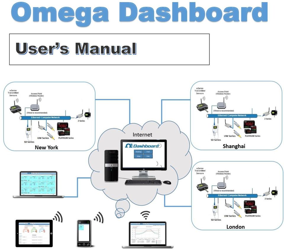
2 PART 1 INTRODUCTION The Dashboard DASHBOARD Web Server The Dashboard is a data logging software application running on a Windows or Linux computer somewhere on the network. The DASHBOARD logs/collects data from the wireless Transmitters. The Dashboard includes a Java-based Web server that can display readings, charts, and record data sent by the transmitters. The readings, data, and charts can be viewed from a Web browser. The browser accessing the Dashboard Web server, can be the same computer on which the Dashboard is installed-- or any other device with Web browsing capabilities on the local network or the Internet (a computer, tablet or smart phone). For Windows PC s The Dashboard runs as a Service in the background, rather than a Program. As long as the computer and its network connection is functioning correctly, the Dashboard will collect data from the transmitters and serve it to Web browsing clients as requested. The Dashboard can also provide data to popular Data Acquisition and Process Control programs running elsewhere on the network. Meanwhile, the computer running the Dashboard server can be used for other tasks. Chart scales are fully adjustable on the fly. For example, the chart can display one minute, one hour, one day, one week, one month or one year. Temperature and humidity can be charted across the full span (-40 to 125 C, and 0 to 100% RH) or within any narrow range such as (20 to 30 C). The OPC Server software makes it easy to integrate the wseries wireless sensor system with many popular Data Acquisition and Automation programs offered by Omega, Wonderware, iconics, Intellution, Rockwell Automation, and National Instruments, among others. The following example illustrates how you can hookup the Dashboard Software/Server to your network: The whole system consists of a single Dashboard and one or more Transmitters or iserver based Ethernet devices. All these devices will send data periodically to the Dashboard software where it serves as a gateway between the users and the Transmitters. The users can access the data through the Dashboard s web server and data acquisition software. A standard web browser can be used to monitor and chart analog current and voltage, temperature, humidity, and barometric pressure. 1

3 Figure 1.1 Dashoboard System on the Ethernet Network 2

4 PART 2 CONFIGURATION 2.1 Configuring the computer running Dashboard Software Disable Power Safe Options: The computer running Dashboard software needs to be running continuously. To do that: a) Go to Control Panel>System and Security>Power Options. Choose the Power Plan>Change Plan Settings>Change Advanced Settings. Then choose the Hard Disk>Turn Off Hard Disk Option. Reduce this number from 20 to 0 (Never). Save the settings. b) These settings may be different on Windows XP. Choose the Option to Never Turn Off Hard Disks and Never Put the System to Standby. Figure 2.1 Power Options IP Address: If this computer is used to run the Dashboard, please set a desired STATIC IP address. Refer to Appendix K to configure the STATIC IP address for Windows. It is recommended to have the computer running Dashboard hard-wired to the access point/wireless router. 2.2 Installing Dashboard Software Find the Dashboardxxx.exe in the accompanying CD or on the web. Double click that to install it. 3


5 The setup process is typical to any Windows program and asks you to choose the installation path and whether it is a new installation or an upgrade. You must have the Administration Rights to the PC when installing the Dashboard Prerequisite Wizard There is a prerequisite wizard to assist you in getting and installing those prerequisites such as Java 32bit or 64bit. The wizard does not show when it does not detect any missing prerequisites, and you can jump to next section Once you click the Next button, your browser will open a website for you to download 4

 from this page.")
6 the missing prerequisites. Since Dashboard needs either 32bit or 64bit version of Java depending on your Windows system, please just download the version it mentioned in the list. For example, here you need to download the 64bit Java from the link Windows Offline (64-bit) from this page. If it needs 32bit of Java or it does not mention the version, you can download the 32bit Java using the other two links on the same page. You can install the prerequisite applications after you download them. 5
 from this page.")

7 After you install all the applications on the list, you can click the Finish button on the Dashboard installation window and continue to install the Dashboard Install Dashboard and Ports Settings If this is the first time installing the Dashboard you can ignore the following installation screen and click Next directly. This notice is only intended for upgrading the software from the previous version, which is formally called Virtual Coordinator. 6

8 Step #1: Install the OMEGA Dashboard, following the installer instructions. Step #2: This computer may have a firewall running which will block the readings sent from the sensor (transmitter) to the Dashboard Software. 7


9 Turn off the Windows Firewall in your Control Panel Security Settings; or Open the Communications Ports (80, 50001, 21, 50002, 50006) so the data can reach the OMEGA Dashboard. Refer to Appendix I and J to configure the firewall. Step #3: Now you are ready to verify the web-server and add your Transmitters/Ethernet based devices. 8

10 2.2.3 Verify your Dashboard web server Once the installation is completed, open up a web browser like Internet Explorer, type in your PC s IP Address and a Dashboard home web page should show up. This means that the Dashboard web-server is running. You can go to any browser and type in the IP address of your computer with the Dashboard installed (the format is for example: : 81, where is the IP of the computer, 81 is the http port. If you set 80 as the port number, you can just type the IP address without port number since 80 is the default http port) using the same computer or any other computer or phone or tablet within the same network. See examples below when the port is 81: Or, when 80 is the port, you only need to type in the IP address without the port number. More info: 9
 using the same computer or any other computer or phone or tablet within the")

11 When you are on the same computer with the Dashboard installed (the server), there are three methods to access the Dashboard homepage in your browser. a. Use the network IP of your computer with the port number: e.g as seen previously. OR, b. Use the string localhost with port number: e.g OR, c. Use the lookback IP of localhost which is with port number: If you try to access the Dashboard from any other devices/computers (the clients) through network, you can only use the network IP (method a) with a port number to access the Dashboard on the server Troubleshooting You can skip this section if you can see the home page of your Dashboard now. If you 10

12 see the HTTP 404 Not Found error message when you visit the Dashboard homepage, in most cases, you need to check if the HTTP server port (it is 80 by default) you assigned has been used by any other applications on your computer. The way to know the usage of a specific port is to run a netstat an find port# command on the Command Prompt. For example, if you want to know if port 80 is taken, you can run command like this: If the port 80 or any other port you assigned as the HTTP server port is taken, you can use Port Settings tool from the Start>All Programs>OMEGA Engineering>Omega Dashboard to change the HTTP Server Port to another port. After that, you are able to use the new port number to access the homepage and check if the new port takes effect. 11

13 The Dashboard web-server is running as Windows services in the background and it runs automatically after computer/server reboot. This helps to acquire the data seamlessly without manual operation. You can go to Start>All Programs>OMEGA Engineering>Omega Dashboard >Uninstall Services (or Install Services) to uninstall the Dashboard web-server or reinstall the Dashboard web-server. 12

14 PART 3 DASHBOARD OPERATIONS 3.1 Dashboard Home Page Once the Dashboard and its Services are installed, you can access the Dashboard using an Internet Browser. Simply, open your browser, type the IP address (with a port number when the HTTP server port is not assigned to the default 80) of the computer on which the Dashboard is installed and you will see the Home Page of the Dashboard as shown in below. The IP address for the Dashboard is the same as the IP address of the computer on which the Dashboard is installed. If the computer has more than one IP address, use the IP address that is on the same network as the Access Point. The Dashboard can be accessed from the same computer on which it s installed or it can be access from a different computer on or outside the local network. Figure 3.1 Dashboard Home Page 3.1 Password Protection There are two kinds of accounts with different username and password for the Dashboard: a. Normal user account: default name is user, default password is , and it can access the Readings, Chart and Data tabs while cannot change the settings through Setup tab. b. Administrator account: default name is admin, default password is , and it can access all the four tabs on the home page. 13


15 The username and password can be changed or disabled. See the Security menu for details. Figure 3.2 Dashboard Log In Page 3.2 Add Ethernet based Devices to Dashboard Dashboard communicates with devices through Ethernet, and it gets data from the iserver on the devices board by sending command periodically. We have two types of Ethernet based devices: 1. Standalone devices with sensor or probe on them (such as isd-th, iseries, Platinum series ), and the iserver is on the device; 2. Coordinator-End Device type system who typically has one coordinator with several end devices, and the iserver is on the coordinator side while end devices connect to sensors or probes. We actually add each end device at a time though the iserver in the coordinator while the coordinator itself is invisible on the Dashboard. That also indicates all the end devices under the same coordinator (iserver) share most of the attributes from the iserver, including MAC Address, IP Address, Admin Password, Protocol, and Port for communication of the iserver. The Device ID (#), Update Rate, Device Name and Device Type are attributes from the end device and they can be different from each other Before You Start You need to prepare the 6 items of your Ethernet Devices/End Devices to add the device to Dashboard. Please check the manual for the specific device to know more information of these items. 1. IP address: The IP address of your Ethernet device. Note: for zseries and UW 14

16 series, it is the IP of the Coordinator (it is an iserver device) is the factory default IP for all of our products. If you have multiple iserver devices to add, please change the IP of your devices and make them have different IP addresses when you do the initial configuration. Please make sure all your Ethernet devices are running by accessing the device webpages on your computer first. For example, to verify the device isd-th is running on the IP : 2. Device Type: such as (ithx-sd, isd-th, isd-tc, ibtx-sd, ZED-TH ). For zseries and UW series or any other Coordinator-End Device type system, it is the type of your End Device you want to add. Please refer to the product to know the device type. You can only add one End Devices at a time. Note: Some of the products may share one Device Type option on the list: ithx-sd/w/m/d: for ithx-sd, ithx-w, ithx-w*, ithx-m, ithx-d with the Temperature and Humidity probe ibtx-sd/w/m/d: for ibtx-sd, ibtx-w, IBTX-M, IBTX-D with the Barometric pressure and Temperature probe ibthx-sd/w/m/d: for ibthx-sd, ibthx-w, IBTHX-M, IBTHX-D with the Barometric pressure, Temperature and Humidity sensor probe ithx-w3/m: for ithx-w3, ithx-m with the with the Temperature and Humidity 15
. For zseries and UW series or any other Coordinator-End Device type system, it is the type of your End Device you want to add.")
17 probe itcx-w/d: for itcx-w, itcx-d with one or two Thermocouples or RTDs ZED-T/TP: for ZED-T, ZED-TP, or any zseries End Device with only one Temperature reading ZED-TH/THP: for ZED-TH, ZED-THP, or any zseries End Device with Temperature and Humidity readings ZED-BT/BTP: for ZED-BT, ZED-BTP, or any zseries End Device with Barometric Pressure and Temperature readings ZED-BTH/BTHP: for ZED-TH, ZED-THP, or any zseries End Device with Barometric Pressure, Temperature and Humidity readings UWTC/UWRTD: for UW series with two Temperature readings RS232 Devices: for iseries and Platinum series with RS232 protocol enabled RS485 Devices: for iseries and Platinum series with RS485 protocol enabled 3. Device #: For standalone devices, it is 0 by default; For zseries and UW series, it is the Device ID you set for the End Device. 4. Admin Password: The admin password of your device/coordinator on the webpage. It is in factory default for all of our products. 5. Protocol: TCP or UDP, defined on the Configuration page on your device webpage, TCP by default. 6. Port Number: 2000 is the factory default value, you may check the port number for TCP or UDP communication on the configuration page of your device. Please refer to your Ethernet Device setting to check the iserver configuration before you add the device: 1. The TCP/ UDP option should be identical to the protocol you used in the OMEGA Dashboard; if your device does not have this option, use TCP by default. 2. Server Type: choose Command. 3. CR or Carriage Return: Choose Enable. 4. Number of connections: Choose at least 2, we suggest you use the Max value of this option. 5. Port: the port number you put in the OMEGA Dashboard when you add the device need to be identical with the port number you set here, the value is 2000 by default. This is the port on the isever board of our product for the Dashboard software to get readings from it. Note: There is another default port number 2000 when you install the Dashboard or do the port setting from the Windows Start menu. And that port is on the 16

18 computer side which is for getting all the data or reading from Dashboard software by sending TCP commands to it. Note: for the devices without some of these options, you can only check the options you have before you add the device. Note: for EIP based zseries (firmware version bigger than 3.0), you also need to check the option called Disconnect After Data Sent (see the Figure below). Please remember if any one of them above is wrong, you will fail to add the device and need to start over! If you have added the device with wrong setting and found that device in the Transmitter pull down list, you need to remove the device first and add it again. Please check the part for removing devices Open the Setup menu This Setup menu has all the configuration options for the Dashboard and the Transmitters/Ethernet devices. The Setup menu is secured with a username and a password as shown in Figure 3.2. The default username is admin and the default password is Add a Device Go to Setup->Network or TX Configuration, click Add iserver If you have added some devices before, the Add iserver option can be found on the 17

19 bottom of the Transmitter list on this page. Input the IP address and choose one device type Input the Admin Password and Device # Note: if your device does not have any password, keep it empty. 18

, you need to choose the protocol as TCP or UDP and input the Port and also input the recording interval in the Update input.")
20 Click Save Changes and then click Confirm. Depends on the network status, it may take several seconds to jump to the next step. When the webpage jumps to the Network configuration page (see below), you need to choose the protocol as TCP or UDP and input the Port and also input the recording interval in the Update input. You can also change the name of the device by checking the Name option. In most of cases, you only need to type in the port number here. After you edit this page, click Save Changes when click Confirm. You can access the setting later if you want to make any change to your settings. 19


21 Note: If you come back to this webpage later to change some settings inside of the Network field set ( such as IP Address, Port Number, Protocol ) that you have already set in the initialization configuration, we recommend you restart the services after the change to prevent unexpected errors! For changing settings outside of the Network filed set, you do not need to restart the service. Since the combination of MAC address and device # makes the unique ID for each device/client, the MAC address and Device # are not editable. The device type is also not editable. If you want to change those fixed settings, you need to remove the device from the Dashboard first and add it back with new settings. You can see the device is now in the Transmitter pull down list. The pull down list includes all the devices you have added to Dashboard. By choosing one item from the list, you can switch to the Setup page of that device or the page to add another device to Dashboard. 20
22 You will see the device on the reading page to verify the device has been added successfully: Tips: How do you restart the services? Go to Start->OMEGA Engineering->Omega Dashboard, click Install Services. If you want to change the HTTP server port or other port settings of your Dashboard, you can use the Port Settings program. If you want to stop running the Dashboard, you can click Uninstall Services. 3.3 Remove the Ethernet based Device from Dashboard You can click the name of the device on the Readings page to jump to the Setup page or 21
23 go the Setup tab and choose one device from the pull down list. If you have assigned a Group to the device, choose the Group of the device first and pick the device from that chosen Group. Then click the Sensors tab on the submenu to jump to the Sensors page. You can uncheck the Activate checkbox if you want to remove the device. Click OK when it shows a popup window. Then click Confirm. 22
24 You will see this message when the device is removed without error. Sometimes when the messages says you need to wait another transmission cycle to finish this, you need to try it again later. Note: the update time we use in this Dashboard is the time the application accesses the Ethernet device (iserver) and gets the reading back, so it might have a minor difference from the records you saved in the SD card in the SD device. Note: The Dashboard web-server is running as Windows services in the background and it runs automatically after computer/server reboot. If any unexpected error occurs, we suggest you restart the services by going to Start->OMEGA Engineering->Omega Dashboard and clicking Install Services. 3.4 TX Configuration Network Once the username and password are entered a set of menu selections will appear starting with the TX (Transmitter) Configuration menu under the Network tab. This page has all the network settings for each Transmitter selected from the top right pull down menu. For Example, in Figure below the selected Transmitter is TX85D6_0. The default name for an Ethernet based Transmitter is TX followed by the last 4 characters of the Transmitter s MAC address (i.e. 85D6) with an underscore and 23
.")
25 then the device# (i.e._0 or _1). For standalone devices, it is 0 by default; and for zseries and UW series, it is the Device ID you set for the End Device. The default name of wseries transmitters have no underscore with the device number, it only has TX followed by the last 4 characters of MAC address (i.e. TX12f6 ). Cookie feature must be enabled for the web browser. TX Configuration Setup Network Page Transmitter Pull down menu of available Transmitters Group Pull down menu of available Groups of Transmitters. Choose a Transmitter: choose a Group from the Group list first and pick the transmitter in the selected Group from the Transmitter list TX Configuration Network field set This field set includes all the important settings for communication with devices. You need to change the settings on this field accordingly after you finish any change on the device side to make the communication continue without error. Once you change any setting inside of this field of this page, a restart of services is necessary to reestablish the communication. Please go to Start->OMEGA Engineering->Omega Dashboard and click Install Services MAC Address 24
26 This is a read-only field displaying the Transmitter s MAC address IP Address This is the static IP address of the Ethernet based Transmitter. The IP address of the standalone Ethernet transmitter (such as isd-th) is unique within the same network. However, for the Coordinator-End Device type devices, all the end devices under the same coordinator share the same IP address, which is the IP address of the Coordinator since the iserver is on the coordinator side. The IP address of the coordinator is unique within the same network. If you have more than one iserver based devices in the same network, you need to assign different IP addresses for them Device Number (Device#) For standalone devices, it is 0 by default; for zseries and UW series or any Coordinator- End Device type devices, it is the Device ID you set for the End Device Admin Password The admin password of your Ethernet device or coordinator for log in to the iserver webpages. It is in factory default for all of our products Protocol TCP or UDP; you need to make sure the protocol you set on the iserver side is the same as the setting here. This is the protocol the Dashboard uses to communicate with the iserver on the Ethernet devices Port Number This is the TCP/UDP port on the iserver side for sending readings to Dashboard is the factory default value, you may check the port number for TCP or UDP communication on the configuration page of your device (iserver) Update This is the Transmitter s data transmission frequency in seconds. Depending on your update rate, your data files can become very large. For example: if you select 1s. One week can equal 604,800 readings or 1 year can equal 31,449,600 readings TX Configuration Transmitter field set Name This is the name of the Transmitter that will appear on the Dashboard s web pages. You can change it by checking the option box on the right and typing the name you want to use for that device. The default name for a Transmitter is TX followed by the last 4 characters of the Transmitter s MAC address (i.e. 85D6) with an underscore and then the device# (i.e._0 or _1). For standalone devices, it is 0 by default; and for zseries and UW series, it is the Device ID you set for the End Device. The default name of wseries transmitters have no underscore with the device number, it only has TX followed by the last 4 characters of MAC address (i.e. TX12f6 ). 25

27 Device Type This is the device type of the device you added, such as (ithx-sd, isd-th, isd-tc, ibtx-sd, ZED-TH ). For zseries and UW series or any other Coordinator-End Device type system, it is the device type of the End Device you have added. Please refer to the product or manual to know more information. To save changes done to the TX Configuration page you must click on the Save Changes button followed by the Confirm button. 3.6 TX Configuration Sensors This page contains the sensor parameters for each Transmitter. Simply, select the Transmitter from the list on the top right as shown in Figure and once the changes are applied click on the Save Changes button followed by the Confirm button. Fields are described below Last Updated This is the date and the time which the Transmitter status was last updated. The date and the time come from the computer on which the Dashboard is installed. Figure Sensors Page for Temperature, Barometric Pressure, and Humidity TX Configuration General Active If checked the Transmitter s readings will be displayed and charted on the Dashboard pages. Inactive/remove device will delete the device from Dashboard. Please refer to section 3.4 Remove the Ethernet based Device from Dashboard for details of 26

28 removing a device Group The Transmitters can be organized on different groups for viewing, readings, chart downloading, data, configuration and command line interface. Once a Group is selected, use the drop down menu for the Group next to the Transmitter drop down menu to view/edit sensor settings TX Configuration Sensor Input Type Depending on your sensor type the title may be Temperature, Barometric Pressure, Humidity, Channel 1 and 2, or Temperature 1 and Unit This determines the units of measurement for that particular sensor. Examples are % for humidity, F or C for temperature, and hpa, inhg, or mmhg for barometric pressure. The unit of Channel type input is editable and will be shown on the Readings and Chart pages. Before adding the customized unit to channel type device, the reading is displayed as gray color. After adding a unit C to it, the unit will be displayed as the global unit for the reading including the readings saved in the.csv files. And according to the unit, the display color will be changed as well. 27

29 Once the unit of measurement is selected it will be a global change throughout the Dashboard, but the unit here is only for Dashboard system, and it does not have any effect on the unit displayed on the device LCD or the unit on the iserver page or the unit in the records inside of the SD card for SD series Latest Values The latest readings are displayed to the right of the Sensors web page to make the adjustment easier if needed. To save changes done to the TX Configuration page you must click on the Save Changes button followed by the Confirm button. 3.7 TX Configuration Alarms The Dashboard can send an if an alarm condition is met. For each Transmitter there are a set of alarm events shown in Figure and described below. The check box is for sending alert when the alarm is triggered. The Indicator check box is for displaying the sensor reading as red color and adding a red dot alarm indicator besides the sensor reading on the Readings page when the alarm is triggered. The figure below shows the Humidity alarm is triggered when the Indicator check box is selected. A Transmitter can be selected from the top right drop-down menu. In order to send alarms you must configure the SMTP settings on the Management page. 28
.")
30 TX Configuration Setup Alarms Page You must check the box for each event and click on Save Changes button Temperature Event The options are High, Low, High/Low and Band. If High is selected the High field must be given a value (higher than that value is an alarm condition). If Low is selected the Low field must be given a value (lower than that value is an alarm condition). If High/Low or Band is selected, both the High and Low fields must be given values (High/Low: outside the band is an alarm condition; Band: inside of the band is an alarm condition). There is a Message box under each event. The text content typed inside the box will be included in the body of the received Barometric Pressure Events The same as Temperature defined above Humidity Events The same as Temperature defined above. 29
31 3.7.4 Channel 1 and Channel 2 Events The same as Temperature defined above Temperature 1 and Temperature 2 Events The same as Temperature defined above Lost Signal Events If the Dashboard does not receive signals from the Transmitter it will send an alarm and Lost will be displayed on the Readings page for that Transmitter. Note: for the Coordinator-End Device type of devices, in most cases, all the end devices with the same coordinator will be Lost at the same time since Dashboard loses the communication with the coordinator they share Probe Disconnected Events If the probe attached to the Transmitter is disconnected that is considered as an alarm condition Low Battery Events Once the batteries inside the Transmitter get lower than the defined Low value, an alarm will be ed. Please make sure the Low value is a reasonable value, so that the Transmitter will still be operating for some time (depending on the transmission frequency) before the batteries are completely drained. Note: All the standalone Ethernet devices do not have this Low Battery Events option since they are all AC/DC powered. It only support wseries, zseries, UW series and all the other Coordinator-End Device type devices. 3.8 TX Configuration System This webpage is only used for upgrading the firmware of wseries through the internal FTP server, and it does not support to upgrade the firmware of Ethernet or iserver based products. Please refer to the manual of wseries for the usage of upgrading the firmware of wseries Transmitter. 30

32 3.9 Dashboard Configuration This page has the configuration settings for the Dashboard shown in Figure. Fields are described below. Figure Dashboard Configuration Page UDP Server Not used for the Ethernet/iServer based products. This is only for the wseries Transmitter, please do not change the value if you are not using wseries products. The default UDP port is Please see the manual of wseries for more information TCP Server Not used for the Ethernet/iServer based products. This is only for the wseries Transmitter, please do not change the value if you are not using wseries products. The default TCP port is Please see the manual of wseries for more information Local Port This is the TCP port number on the Dashboard (physically, on the computer side where it has Dashboard installed) to which different commands can be sent to get data of one or group of devices. The commands can be used by third party software to get the data from the Dashboard. Note: Do not confuse this Local Port number on the computer side with the Port Number (default is 2000) on the Ethernet/iServer board of the device side when you add a device to Dashboard. And that Port Number is used for the Dashboard to send command to device and get readings from it. The Port Number for each device is also displayed on the Network configuration webpage (see section 3.5) and it should be identical to the port configuration of the device to get data from device Close Connection After Data Sent If checked, once the Dashboard responds back with data, it will close the TCP 31

33 connection (on Local Port) that had been made from a network host. This feature should be used if data acquisition software expects data to be ended by closing TCP connection from the client OPC Server This option should be checked only when the OPC server is used. You will need to change the Transmitter s label to be 000, 001, Refer to the web for instructions on configuring the OPC server for wseries Products Time Stamp If checked the Dashboard will respond to the commands starting with date and time Reading Unit If checked the Dashboard will respond to the commands with reading units Overview field set This part contains the information of Dashboard system including Dashboard Version, the current Date and Time, and Uptime which indicates how long Dashboard has been running Management The Dashboard can send an if an alarm condition is met. This page provides the SMTP (Simple Mail Transfer Protocol) settings needed to generate s (Figure below). For the actual alarm events for each Transmitter refer to Section 3.7. Fields are described below. Figure Management Page 32
34 Enabled If checked the SMTP is enabled on the Dashboard. If unchecked, the alert function is disabled as well SMTP Server This field specifies the IP Address or domain name of the SMTP server. For some public SMTP server, you can search online to get the server address. For example, Gmail SMTP server is smtp.gmail.com according to the Google webpage You must have an server (SMTP server) in order to receive s generated by the Dashboard SMTP Server Port This specifies the TCP port used by the SMTP Server. You need to change it according to instructions provided by your SMTP service provider. For example, Gmail SMTP server port is 465 for SSL security, and 587 for TLS security, according to the Google webpage Security This is the authentication type the server may require. The options are SSL and TLS. The default is None. When security option is changed, the SMTP server port usually needs to be changed accordingly Username / Password If authentication is required for your SMTP server, a username and a password must be entered. Username and password are case-sensitive From This is a text field and could be a name, a location, or an address To This field specifies the addresses or group address of the recipients. It can take up to 412 alphanumeric characters. addresses should be separated by a comma and a space. For example: [email protected], [email protected] Note: To receive an alert text message, you can put the address for your phone number provided by your phone service company here. For example, AT&T wireless device has the address [email protected] for each phone number, which is the 10-digit wireless phone number, followed [email protected]. Please see Appendix L for more information about sending alert text messages. Check each individually, if one is wrong none of the other s will go through. 33

35 Subject This field specifies the subject of the . s for all the alarms will have this common subject line. Example of a subject would be Temperature Alarm Reminder Interval This will force an to be resent if the alarm condition is still met. The minimum value is 1 minute and if it s set to 0 the Dashboard will not send a reminder Transmission Delay If there is an alarm condition the Dashboard will not send an until this delay period is expired. If it s set to 0 s will be sent immediately once the alarm condition is met. Usually, the Transmission Delay should be longer than the update interval of the device reading. Note: The Transmission Delay can be worked to avoid momentary alarm condition. For example, the Reminder Interval is set as 10 minutes, Transmission Delay is set as 3 minutes, and the update interval of device reading is 10 seconds. When the first time the alarm condition is triggered, the system will watch the alarm for 3 minutes. At the same time, the reading is updating each 10 seconds. If the alarm condition lasts for 3 minutes, the first will be sent at the end of that 3 minutes or if the alarm is gone within the 3 minutes, the will not be sent. After the first alert is sent, the system will send one alert each 10 minutes repeatedly (set by the Reminder Interval) if the alarm condition is still there. 3.11Security This page provides security and access settings for the Dashboard. Fields are described below. Figure 3.11 Security Page Admin A username and a password can be set for someone who is authorized to access all the menus and pages within the Dashboard. The default username is admin and the default password is To change the name and password of the admin account or disable the admin account, please click Change on the admin row to jump to the webpage below. Click Save Changes to save the new settings. 34
36 Caution: When you disable the admin password but have user password enabled, the user account becomes invalid, and all the webpages of the Dashboard can be accessed without any password User A username and a password can be set for someone who is authorized to access Readings, Chart, and Data menus only; the Setup menu cannot be accessed. The default username is user and the default password is To change the name and password of the admin account or disable the admin account, please click Change on the admin row to jump to the webpage below. Click Save Changes to save the new settings Diagnostics This page provides diagnostic information regarding power, signal, etc. for all the Transmitters. Fields are described below. Note: The Power type, Battery, Signal Strength and Success Rate are only for the based wseries devices and based Coordinator-End Device type devices (i.e. zseries). For iserver/ethernet based standalone devices, Dashboard shows N/A on those columns. 35

37 Figure 3.12 Diagnostic Page Name This is the Transmitter s name. You can jump to the Setup page of the device by click at the Transmitter s name. You can also change the Transmitter s name on the Setup page Latest This is the last date/time the Dashboard received a packet of data from the Transmitter Power This indicates whether the Transmitter or End Devices is powered by an AC adapter or battery. Some transmitters with AC adapter have battery back-up. It only supports the based wseries devices and based Coordinator-End Device type devices (i.e. zseries), and it shows N/A for iserver/ Ethernet standalone devices Battery This indicates the voltage level in the battery. It only supports the based wseries devices and based Coordinator-End Device type devices (i.e. zseries), and it shows N/A for iserver/ Ethernet standalone devices. Some transmitters with AC adapter have battery back-up; therefore, their voltage level is also displayed. A new alkaline battery regardless of its type (AA or C-cell) has about 1.59 volts. For wseries Transmitters : The two C-cell batteries in battery-powered wseries Transmitters are wired in parallel; therefore, the combined voltage level is the same as a single battery. For zseries End Devices: The full voltage level is above 3V. It is recommended to change the batteries when the voltage level gets equal to or below 2.7V Signal Strength This is the strength of the radio signal. It only supports the based wseries devices and based Coordinator-End Device type devices (i.e. zseries), and shows N/A for iserver/ Ethernet standalone devices. For wseries, it is the signal strength between the wseries Transmitter and the Access Point. For based Coordinator-End Device type devices, it is the signal strength between the End Device and Coordinator. The higher the signal strength is the better communication would be. 36
38 For wseries Transmitters: With a Signal Strength of over 20% you have a stable wireless communication. If the Signal Strength falls below 20% and stays for a long period of time you should check the Transmitter for distance and interference. If the Power Save mode is enabled the Signal Strength will only be updated if there is a packet loss. For zseries Devices: It must be noted that although the Signal Strength value being reported may be very low this does not mean that the device will not be able to receive frames reliably. It is simply indicating that the modem gain has been set to its highest level in order to receive the frame which also means highest power consumption Success Rate A low success rate indicates a longer data delay, shorter battery lifetime and high network traffic. It only supports the based wseries devices and based Coordinator-End Device type devices (i.e. zseries), and shows N/A for iserver/ Ethernet standalone devices. If the Success Rate is 100% that indicates that there is no packet loss. Having Success Rates of less than 100% is normal since the Transmitter will retransmit the lost packets Update This is the device s reading transmission frequency in seconds. For example, if it s set to 5 seconds then it means that the Dashboard will update device reading every 5 seconds. The default value is 10 seconds for all the devices. Shorter update interval means more network traffic and higher system usage Logout Once the Logout option is clicked the user will be logged out from the Dashboard. The user will be logged out automatically by closing the browser or by no longer browsing (active data readings, chart, sensor setup and diagnostics will keep login session active). 37
39 3.14 Readings This page displays the readings from all the added devices. Up to 12 devices can be displayed on each page. To see more devices on the next pages, click on Prev/Next (not shown when less than 12 devices on Dashboard) at the bottom of the page. By choosing a group from the Group pull down list, you can switch to another group. Figure below describes the fields of device reading block. By click on the Device Name, you can directly go to the Setup page of that device. 38

40 Error Messages The Reading page also shows error messages such as Open, Lost, LostED. Open : the probe or sensor is disconnected on the device. Lost : Dashboard loses the communication with the device. Note: If Dashboard loses the communication with the Coordinator of the Coordinator-End Device type system, all the End Devices under that Coordinator show Lost. LostED : only for the End Device of the Coordinator-End Device type system, it means the Coordinator loses the communication with that End Device while the Dashboard can still communicate with the Coordinator. Note: If an End Device has never established the communication with the Coordinator since the Coordinator powers up, it shows Lost instead of LostED Chart This page charts the readings for each Transmitter in real-time as well as the recorded data. Select a Transmitter from the list on the top right as shown in Figure 4.14 and the charting will start with a default one-minute period. If you have different groups of 39
41 devices, choose Group first and then choose a device from the Transmitter list. Along the chart line there are pointers that would display time-stamped sensor readings once they re pointed with the mouse. Figure 3.15 Chart Readings Page 40

42 A- Transmitter list to switch among different devices B- Current time and current reading C- Reading point tracker: move your mouse on one point to know the reading and the time stamp for it. D- Axes for all the sensors/measured channels E- Time Stamps for Chart F- Color Indicator for all Sensor Readings with Sensor Type and Unit G- Chart Display Control Field Data Source The options are Live and Recorded. If Live is selected the real-time data will be charted as a function of time period. If Recorded option is selected the past saved data will be charted per selected time period. A click on the OK button is needed to execute the change Period This determines the time period in which the live or recorded data is charted. A click on the OK button is needed to execute the change. Note: for any reason (such as computer reboot or losing communication for some time) when the reading update is interrupted, the Chart shows a blank gap on the reading trend line to indicate the interrupt. 41

43 End Date This field is active only in Recorded mode. Once it s active a date can be selected to chart the recorded data up to that date, which would be the end of the chart. The End Date can be chosen from a calendar where the word choose is located. A click on the OK button is needed to execute the change. Selecting an End Date is mandatory to chart recorded data. It s always important to first select a desired chart Period before picking an End Date Scale Setting This section allows changing the upper and lower values for the x axis on the graph. Simply, put the numbers in the min. and max. boxes and the axis limits will change accordingly Display Choice In cases where there are less points used to create a chart than what the actual collected points are choices are given to chart the minimum and maximum (min max), only minimum (min), or only maximum (max) points for any given period. In the case of min max there could be two charts; one representing all the maximum readings and the other one representing all the minimum readings. This could happen if there are sudden and continuous changes with any of the sensor readings. Once you leave the chart page for a Transmitter all the settings will get saved Gauge This page illustrates the readings in gauge format. Once the Show Setting box is checked you will be able to scale the gauge with the Start and End reading values as well as defining the Red Range as shown in Figure Click on the Save Settings button to save new settings. For Analog Gauges you can eliminate the extra digits by changing the Settings: Start: 0 End: 60 Figure 3.15 Gauge Readings Page 3.16 Data Data from all the active Transmitters gets recorded in the same computer on which the Dashboard is installed. The Data page has options to retrieve currently recorded data as well as the data that was recorded in the past called Archived Recorded Data as shown in Figure Every time the Transmitter is rebooted the current recorded data file 42


44 moves into the archived recorded data and a new log file will be generated under the current recorded data. Please choose from the Group list to switch to another group of devices. The name of the data file in the Archived Recorded Data is based on the date and the time the data file was moved into the Archived Recorded Data which is the same as when the Transmitter was rebooted. Figure 3.16 Data Page All the recorded data files are in.csv (Comma Separated Value) format and can be easily imported into a spreadsheet program like Excel. Figure 3.17.csv Recorded Data Files 43
45 APPENDIX A GLOSSARY User of this manual should be familiar with following definitions: ARP (Address Resolution Protocol) is a protocol for mapping an Internet Protocol address (IP address) to a physical machine address that is recognized in the local network. For example, the IP (IPv4) address in use today is an address that is 32-bits long. In an Ethernet local area network, however, addresses for attached devices are 48-bits long. (The physical machine address is also known as a Media Access Control or MAC address.) A table, usually called the ARP cache, is used to maintain a correlation between each MAC address and its corresponding IP address. ARP provides the protocol rules for making this correlation and providing address conversion in both directions. Coordinator-End Device type network has the star network typology which has several End Devices communicating to a Coordinator wirelessly. End Device has sensors or probes on it while Coordinator with an iserver collects data from End Devices and sends data to Dashboard through Ethernet (connected by RJ45 connector). Ethernet is a network protocol defined by the IEEE standard. Ethernet-based networks use MAC Address rather than IP Address to exchange data between computers. By using ARP and adding TCP/IP support, Ethernet devices may be connected as part of the Internet. An Ethernet LAN typically uses coaxial cable or special grades of twisted pair wires. The most commonly installed Ethernet systems are called 10BASE-T and provide transmission speeds up to 10 Mbps. Devices are connected to the cable and compete for access using a Carrier Sense Multiple Access with Collision Detection (CSMA/CD) protocol. HTTPS (also called HTTP over TLS, HTTP over SSL, and HTTP Secure) is a protocol for secure communication over a computer network, it authenticates a server with a certificate and encrypts the data for communication. IEEE b/g is the wireless Wi-Fi standard used by our wseries. IEEE is the low data rate wireless standard used by our zseries, UW series and ZW series. IP (Internet Protocol) is the method or protocol by which data is sent from one computer to another on the Internet. IP address (Internet Protocol address) is a 32-bit number that identifies each sender or receiver of information that is sent in packets across the Internet. IP Netmask is a 32-bit pattern of bits used to determine which part of the IP address is the network portion and which part is the host portion. MAC (Media Access Control) Address is your computer's unique hardware number. When you're connected to the Internet from your computer, a correspondence table relates your IP address to your computer's physical (MAC) address on the LAN. Ping is a utility that tests the network connectivity. It is used to determine if the host is capable of exchanging information with another host. Port number/socket number is a way to identify a specific process to which an Internet or other network message is to be forwarded when it arrives at a server. It is a 44
46 APPENDIX A GLOSSARY (continued) predefined address that serves as a route from the application to the Transport layer or from the Transport layer to the application of the TCP/IP system. Standalone iserver based device has sensors/probes connected to it directly and uses the iserver inside to transmit data through Ethernet (connected RJ45 connector). Sockets are a method for communication between a client program and a server program in a network and defined as "the endpoint in a connection". Information transferred across the Internet primarily occurs between sockets. SMTP Simple Mail Transfer Protocol is an Internet standard for electronic mail ( ) transfer across the Internet. SMTP clients usually use SMTP to send messages by specifying the SMTP server. The server uses SMTP to both send and receive messages. SNMP Simple Network Management Protocol is a network monitoring protocol to monitor devices connected to an Ethernet Network. SSL and TLS are both standard security technology for establishing an encrypted link between a server and a client typically a web server (website) and a browser; or a mail server and a mail client. TLS (Transport Layer Security) is the successor to the Secure Sockets Layer (SSL). TCP/IP (Transmission Control Protocol/Internet Protocol) is the basic communication language or protocol of the Internet. When you are set up with direct access to the Internet, your computer is provided with a copy of the TCP/IP program just as every other computer that you may send messages to or get information from also has a copy of TCP/IP. TCP/IP often is used as a general term to indicate generic access to the Internet. UDP/IP (User Datagram Protocol/Internet Protocol) is the TCP/IP standard protocol that allows an application program on one machine to send a datagram to an application program on another. The UDP can be either in Broadcast or Directed form. The Broadcast UDP transmits data to every node on the same network. The Directed UDP transmits data to one node only. WEP (Wired Equivalent Privacy) a security algorithm for IEEE wireless networks. Provides data confidentiality comparable to that of a traditional wired network. Recognizable by the key of 10 or 26 hexadecimal digits, is widely in use and is often the first security choice presented to users by router configuration tools. WPA Wi-Fi Protected Access and WPA2 Wi-Fi Protected Access II WPA2 provides stronger data protection and network access control. WPA2-PSK (Pre-shared key) mode encrypts the network traffic using a 256 bit key. This key can be entered as a passphrase of 8 to 63 printable ASCII characters. Enterprise Mode (Business, Government, Education) Personal Mode (SOHO, Home/Personal) WPA Authentication: IEEE 802.1X/EAP Encryption: TKIP/MIC Authentication: PSK Encryption: TKIP/MIC WPA2 Authentication: IEEE 802.1X/EAP Encryption: AES-CCMP Authentication: PSK Encryption: AES-CCMP 45
47 Appendix B IP Address An IP address is a unique 32-bit address assigned to a computer and includes: A network ID number identifying a network. A host ID number identifying a computer on the network. All IP addresses have been divided into three smaller groups (classes) A, B and C Class A addresses have 8-bits of network ID and 24-bits of host ID. They can support a large number of hosts, approximately 2 = 16,777,216 computers per network. The IP addresses range in binary from xxxxxxxx.xxxxxxxx.xxxxxxxx to xxxxxxxx.xxxxxxxx.xxxxxxxx The IP addresses range in decimal from 1.x.x.x to 127.x.x.x Class A network ID s support a very large number of hosts. Class B addresses have 16-bits of network ID and 16-bits of host ID. They can support approximately 2 16 = 65,536 computers per network. The IP addresses range in binary from xxxxxxxx.xxxxxxxx to xxxxxxxx.xxxxxxxx The IP addresses range in decimal from x.x to xxx.xxx Class B network ID s support a medium number of hosts. Class C addresses have 24-bits of network ID and 8-bits of host ID. They can support approximately 2 8 = 256 computers per network. The IP addresses range in binary from xxxxxxxx to xxxxxxxx The IP addresses range in decimal from xxx to xxx Class C network ID s support a small number of hosts. The rest of the addresses are divided into two classes, D and E. Class D networks are not assigned to the host. They are used for multicasting. The address range from 224.x.x.x to 239.x.x.x Class E networks are experimental or reserved addresses. The address range from 240.x.x.x to 247.x.x.x 46
48 Appendix C IP Netmask IP Netmask or Subnet Mask is a 32-bit pattern of ones and zeros used to determine network portion of an IP address from the host portion of the IP address. Subnet mask is a network ID that is created by borrowing bits from host portion of IP address and using them as part of a network ID. The table below shows a default subnet mask for address Classes A, B, and C. Each bit that is set to "1" in the subnet mask corresponds to the bit in the IP address that is to be used as the network ID. Each bit that is set to "0" in the subnet mask corresponds to a bit in the IP address that is to be used as the host ID. Address Class Mask Binary Value Mask Decimal Value or Dotted Notation Class A Class B Class C If your network requires more network ID s, you can extend the default subnet mask to include additional bits from the host ID. This allows for additional network ID s within the network. The table below shows some examples of subnet masks and bits moved from the hosts ID to create a new subnet. Mask Dotted Notation Mask Binary Mask Bits Class A (Default) (Default) (Default) Class B Class C To determine the number of valid hosts ID s remaining after subnetting, use the following equation: 2 n 2, where n is the number of octet digits left after the subnet mask
49 Appendix D ASCII Chart ASCII Char Dec Hex Binary No Parity ASCII Char Dec Hex Binary No parity NUL SOH A STX B ETX C EOT D ENQ E ACK F BEL G BS H HT I LF 10 0A J 74 4A VT 11 0B K 75 4B FF 12 0C L 76 4C CR 13 0D M 77 4D SO 14 0E N 78 4E SI 15 0F O 79 4F DLE P DC Q DC R DC S DC T NAK U SYN V ETB W CAN X EM Y SUB 26 1A Z 90 5A ESC 27 1B [ 91 5B FS 28 1C \ 92 5C GS 29 1D ] 93 5D RS 30 1E ^ 94 5E US 31 1F _ 95 5F SP ` ! a " b # c $ d % e & f g ( h ) I * 42 2A j 106 6A B k 107 6B , 44 2C l 108 6C D m 109 6D E n 110 6E
50 Appendix D ASCII Chart Continuation / 47 2F o 111 6F p q r s t u v w x y : 58 3A z 122 7A ; 59 3B { 123 7B < 60 3C C = 61 3D } 125 7D > 62 3E ~ 126 7E ? 63 3F DEL 127 7F ASCII Control Codes ASCII Dec Hex Ctrl Key Definition ASCII Dec Hex Ctrl Key Char Equiv. Char Equiv. Definition NUL Null Character DC Crtl Q Data Control 1 - XON SOH Crtl A Start of DC Crtl R Data Control 2 Header STX Crtl B Start of Text DC Crtl S Data Control 3 - XOFF ETX Crtl C End of Text DC Crtl T Data Control 4 EOT Crtl D End of Transmissio NAK Crtl U Negative Acknowledge ENQ Crtl E n Inquiry SYN Crtl V Synchronous Idle ACK Crtl F Acknowledge ETB Crtl W End of Trans Block BEL Crtl G Bell CAN Crtl X Cancel BS Crtl H Back Space EM Crtl Y End of Medium HT Crtl I Horizontal SUB 26 1A Crtl Z Substitute Tabulation LF 10 0A Crtl J Line Feed ESC 27 1B Crtl [ Escape VT 11 0B Crtl K Vertical FS 28 1C Crtl \ File Separator Tabulation FF 12 0C Crtl L Form Feed GS 29 1D Crtl ] Group Separator CR 13 0D Crtl M Carriage RS 30 1E Crtl Record SO 14 0E Crtl N Return Shift Out US 31 1F Crtl _ Separator Unit Separator SI 15 0F Crtl O Shift In SP Space DLE Crtl P Data Link Escape 49
51 Appendix E TCP/IP COMMAND-LINE-INTERFACE The Dashboard responds to TCP connections made to its port From anywhere on the network, data acquisition programs that support TCP/IP protocol or applications like Telnet can establish a TCP port connection to the Dashboard using its IP address and port The IP address of the Dashboard is the same as the IP address of the PC on which the Dashboard is installed. The default local port 2000 can be changed in the Dashboard if needed (see Dashboard Configuration Section 3.9). Once the TCP connection is established, the commands listed below can be used to query the Dashboard for real-time data from any or all the Transmitters. The commands sent to and the responses back from the Dashboard are all in ASCII format. Commands Descriptions ERDALL Collects readings from the Dashboard for all the Transmitters. Example: This is the response to ERDALL command for 4 transmitters. 2011/07/22 12:06:57 TXd461_ C 2011/07/22 12:06:47 TXd201_ C 24.0 C 2011/07/22 12:06:43 TX5a86_ C 47.0 % 2011/07/22 12:06:57 TXd4e4_ C hpa 48.6 % e Transmitter Name Temperature Barometric Pressure Humidity ERDBxxxxxx Collects readings from the Dashboard for a single Transmitter. xxxxx would be the Transmitter s name. Example: This is the response to ERDBTXd4e4 command. 2011/07/22 12:07:16 TXd4e4_ C hpa 48.6 % ERDRxxxxxx# Collects readings from the Dashboard for a specific sensor of a single transmitter. xxxxxx would be the Transmitter s name and # would be the first (c), second (d), or third (e) sensor reading. Example: This is the response from the Dashboard to the command ERDRTXd4e4c for the temperature reading of transmitter TXd4e /07/22 13:59:17 TXd4e4_ C ERDGx Collects readings from the Dashboard for a group of transmitters where x is the letter for that group (A, B, C,.). To put the Transmitters in a group, see Section 4.4 Example: This is the response from the Dashboard to the command ERDGA where A is a group with three devices. 2011/07/22 14:41:58 TXd4e5_ C hpa 49.2 % 2011/07/22 14:42:00 TXd503_ C 50.9 % 2011/07/22 14:41:55 TXd4ae_ C 21.7 C The commands are not case-sensitive and should be sent followed by a carriage return 50
52 Appendix F ASCII / TELNET COMMANDS TABLE Table F.1 ASCII/Commands Table Command Device / Group ID Description (see notes below if *) Example ERD ALL Get all sensor readings ERDALL ERDB Device Label Get sensor readings of an Transmitter Get reading for sensor txd430: ERDBtxd430 ERDR Device Label: Reading/parameter: a-s *1 Get individual reading or parameter Get the first temp. reading for sensor txd430: ERDRtxd430c ERDG Group Label: A-Z; ALL Get sensor readings of a group / groups of sensors EQNF Device Label Get label, status and firmware version of an Transmitter EQNG Group Label: A-Z, ALL Get label, status and firmware, version of a group/all groups of sensors EQPE Device Label Get sleep period, battery voltage, signal strength, success of an Transmitter EQPG Group Label: A-Z Get sleep period, battery voltage, signal strength, success, of a group / all groups of sensors Get readings for all group B: ERDGB Get label for sensor txd430: EQNFtxd430 Get label for all sensors: EQNGALL Get sleep period for sensor txd430: EQPEtxd430 Get sleep period, of group B: EQPGB *1 Refer to Table F.3 Note: EQNF, EQNG, EQPE and EQPG commands only work for wseries transmitters, and cannot work with any other devices. An example of the status of a Transmitter Command: EQNF003 Response: 2011/08/02 17:51: is the label for the Transmitter. " " is the bitmap representation of the internal state. The meaning for each bit is described below (bit 7 starts from the left) is version of the firmware in the Transmitter Table F.2 Status of the device Bit 7 shows if the sensor is plugged into the Transmitter. 1 means there is no sensing device detected. Bit 6 shows if the communication to the Transmitter is lost. 1 means there has not been any data received from that particular Transmitter for 1 minute or 4 times the update rate, whichever is a longer time interval. Bit 5 not used. Bit 4 not used. Bit 3 not used. Bit 2 not used. Bit 1 shows the source of power supply to the Transmitter. 1 means it s powered by an adapter and 0 means it s powered by batteries. Bit 0 not used. 51
53 Appendix F ASCII / TELNET COMMANDS TABLE (continued) Table F.3 Reading/parameter for ERDR commands Options (lower case) a b c d e f i j k l q r s Reading/parameter Sequence number (Always 1, as timestamp is used for sequence number) Device type reading / error message reading / error message reading / error message not used Update rate Battery voltage (no decimal point) Signal strength Success rate Name (Label) Status (see previous table) Firmware version Option Chart for sensor reading order c d e Temp Temp RH Temp Pressure Temp Pressure RH Temp TC Temp TC Analog Analog * See option chart for sensor reading order Note: b,j,k,l,r,s are perimeters only for wseries and not working with any other devices. Table F.4 Connector/Transmitter Types for wseries Model Description Type# wtp1 Temperature sensor with stick probe 16 wtp2 Temperature sensor with lug mount probe 16 wthp Temperature and humidity sensor 15 wthp2 Temperature and humidity sensor, short probe 15 wbthp Barometric pressure, temp and humidity sensor 13 wbtp Barometric pressure and temperature sensor 9 wtc Dual thermocouple inputs 20 wvi Analog input, Channels Enabled 24 wvi Analog input, Channel 1 Enabled 25 wvi Analog input, Channel 2 Enabled 26 52
54 Appendix G HTTPget Program This is a DOS-based TCP socket connection program used to query real-time data from the Dashboard. Simply, download this single httpget.exe file from our web site and place it somewhere in your computer s hard drive. At the DOS prompt where the httpget.exe is residing a command string can be sent to the Dashboard to receive real-time data. The figure below demonstrates the HTTPget command strings. HTTPget Command Strings 53
55 Appendix H Troubleshooting Once you apply the steps described in Section 2 and 3 and if you still cannot see the Transmitter on your Dashboard check the following items: Wired LAN If your computer is on a wired LAN on which the correct access point is also connected, make sure that you can reach the access point from your computer. This can be accomplished by pinging the IP address of the access point. Firewall Make sure that the firewall is off or the exceptions are added properly. Refer to Appendix I and J. FIREWALL FAQs: Question 1: My firewall is ON and I unchecked the exception for those ports but still the readings are seen on the webpage? Solution: Go to Control panel->administrative tools->services and restart the Windows Firewall /Internet Connection sharing service. Question 2: My firewall is ON and I removed the exception for those ports but still the readings are seen on the webpage? Solution: Same as Question 1. Question 3: My firewall is ON and I removed the exception for those but still the readings are seen on the webpage and I tried solution 1? Solution: In Internet explorer go to and do the express upgrade to make sure that all the needed patches and service packs are installed. Then try Solution 1. IMPORTANT NOTES: Refer to each section listed below for additional details. DASHBOARD OPERATIONS: Network Connection for Dashboard: It is recommended to have the computer running Dashboard hard-wired to the access point/wireless router with a static IP address. The IP address for the Dashboard is the same as the IP address of the computer on which the Dashboard is installed. If the computer has more than one IP address, use the IP address that is on the same network as the Access Point. The Dashboard can be accessed from the same computer on which it s installed or it can be access from a different computer on or outside the local network. 54
 with an underscore and then the device# (i.e._0 or _1).")
56 Appendix H Setup Menu Troubleshooting (continued) The username and password can be changed or disabled. See the Security menu for details. TX Configuration Network The default name for a Transmitter is TX followed by the last 4 characters of the Transmitter s MAC address (i.e. 85D6) with an underscore and then the device# (i.e._0 or _1). For standalone devices, it is 0 by default; and for zseries and UW series, it is the Device ID you set for the End Device. The default name of wseries transmitters have no underscore with the device number, it only has TX followed by the last 4 characters of MAC address (i.e. TX12f6 ). Cookie feature must be enabled for the web browser If the Network page shows the wrong layout (such as the webpage below shows the layout for non-wseries with a wseries device type layout), please click the Setup tab on this page to load the correct layout. 55

57 The correct layout for this device should be: Network Network DHCP for Devices To conserve battery power it s strongly recommended to use a STATIC IP address (DHCP un-checked) for your Transmitter and Ethernet devices you before you add them to Dashboard. Network Dashboard IP Address You need to make sure that the IP address for the Dashboard will not change; otherwise, the Transmitter will not retain its connection with the Dashboard. For this reason using a STATIC IP address for the Dashboard is strongly suggested. If using DHCP for the Dashboard IP, reserve the assigned IP Address in the DHCP Server table to ensure the Dashboard always gets the same IP Address. Port If the default port number (2000, or 50006) is not available, then use another number, and change the setting in the Dashboard Manager. Network Transmitter Update Depending on your update rate, your data files can become very large. For example: if you select Continuous which is about 3 readings per second. One week can equal 1,814,400 readings or 1 year can equal 94,348,800 readings. For example: if you select 1s. One week can equal 604,800 readings or 1 year can equal 31,449,600 readings. 56
58 Appendix H Troubleshooting (continued) TX Configuration Sensors Group Once a Group is selected, use the drop down menu for the Group next to the Transmitter drop down menu to view/edit sensor settings. TX Configuration Sensor Input Type Unit Once the unit of measurement is selected it will be a global change throughout the Dashboard, but the unit here is only for Dashboard system, and it does not have any effect on the unit displayed on the device LCD or the unit on the iserver page or the unit in the records inside of the SD card for SD series. Note: for wseries devices, the unit change also takes effect to the unit on the wseries LCD. TX Configuration Alarms A Transmitter can be selected from the top right drop-down menu. In order to send alarms you must configure the SMTP settings on the Management page. You must check the box for each event and click on Save Changes button. Temperature Events There is a Message box under each event. The text content typed inside the box will be included in the body of the received . TX Configuration System (for wseries devices only) The new firmware should be placed in your Dashboard s directory at Dashboard\ftpserver\res\home\public before the firmware upgrade is initiated. Refer to the web for step by step instructions. It takes about two minutes for a complete firmware upgrade. You can start firmware upgrade on one Transmitter and then move to the next ones. Username / Password You can always use a different FTP server by simply providing the above parameters for that FTP server. 57
59 Appendix H Troubleshooting (continued) Chart Along the chart line there are pointers that would display time-stamped sensor readings once they re pointed with the mouse. End Date It s always important to first select a desired chart Period before picking an End Date. Display Choice Once you leave the chart page for a Transmitter all the settings will get saved. Gauge For Analog Gauges you can eliminate the extra digits by changing the Settings: Start: 0 End: 60 Data The name of the data file in the Archived Recorded Data is based on the date and the time the data file was moved into the Archived Recorded Data which is the same as when the Transmitter was rebooted. 58
60 Appendix I Firewall Settings for Windows XP and Vista Firewall protects a computer from external attacks. They typically restrict connections to all the ports on a computer that an external program can connect to. But there are times when you need to allow external programs to send data to your PC. To do that, you add exceptions to the firewall. This involves opening up only certain ports. Ports are of type UDP or TCP. I.1 First go to Control Panel and click the icon of Windows Firewall. In case of Windows Vista, the icon is under System and Security. I.2 In General tab, Make sure that the firewall is ON and the checkbox for Don t allow exceptions is unchecked. Now, click the Exceptions tab. Figure I.1 Control Panel Figure I.2 General Tab 59
61 Appendix I Firewall Settings for Windows XP and Vista (continued) I.3 Click the button that says Add Port to add a UDP/TCP port. Figure I.3 Exceptions 60
62 Appendix I Firewall Settings for Windows XP and Vista (Continued) I.4 Add the UDP port first that is used for Transmitter data to the Dashboard. Figure I.4 Add a Port - TCP Similarly add TCP ports for (TCP port for transmitter data), 2000 (command local server), 21 (ftp port for firmware upgrade), 80 (TCP type for HTTP web server). Figure I.5 Add a Port - TCP Figure I.6 Add a Port - TCP Figure I.7 Add a Port - TCP Figure I.8 Add a Port - TCP 61
63 Appendix I Firewall Settings for Windows XP and Vista (continued) I.5 Restart the Windows Firewall service. Go to Control Panel->Administrative tools->services. Locate the Windows Firewall/Internet Connection Sharing service and restart it. For Windows Vista the name of the service is Windows Firewall only. Figure I.9 Services 62
64 Appendix J Firewall Settings for Windows 7 and Server 2008 Firewall protects a computer from external attacks. They typically restrict connections to all the ports on a computer that an external program can connect to. But there are times when you need to allow external programs to send data to your PC. To do that, you add exceptions to the firewall. This involves opening up only certain ports. Ports are of type UDP or TCP. J.1 First go to Control Panel and click the icon of System and Security. Choose the Windows Firewall. Figure J.1 System and Security Figure J.2 Windows Firewall Click the option to Turn Windows Firewall ON or OFF. Figure J.3 Turn Windows Firewall ON or OFF 63
65 Appendix J Firewall Settings for Windows 7 and Server 2008 (continued) J.2 Turn ON the firewall and check the option to Notify when Firewall blocks a program. Figure J.4 Turn Windows Firewall ON J.3 Go to Advanced settings to open the desired ports. Figure J.5 Windows Firewall - Advanced Settings 64
66 Appendix J Firewall Settings for Windows 7 and Server 2008 (continued) Then choose the section of Inbound Rules. The exceptions apply to Inbound Rules (incoming connections to the PC). Choose the New Rule link on the right side under the tab Actions. Figure J.6 Windows Firewall - Inbound Rules Choose the option to create a rule for a particular port and click Next. Enter the port number (or whatever is the port for TCP data communication between transmitter and Dashboard) and choose type of TCP. Figure J.7 Windows Firewall - Figure J.8 Windows Firewall - Rule Type Protocol and Ports Choose Allow the connection. We are allowing data from this port. Then choose the profile for Domain, Private and Public networks. Figure J.9 Windows Firewall - Action Figure J.10 Windows Firewall - Profile 65
67 Appendix J Firewall Settings for Windows 7 and Server 2008 (continued) Give a name for the rule. We give virtual_coordinator_tcp port. J.4 Now do the same thing for UDP based port Figure J.11 Windows Firewall -Name Figure J.12 Figure J.13 Windows Firewall -Protocol and Ports Windows Firewall - Name Then for FTP firmware upgrade port 21. Figure J.14 Figure J.15 Windows Firewall -Protocol and Ports Windows Firewall - Name 66
68 Appendix J Firewall Settings for Windows 7 and Server 2008 (continued) Add the port 2000 for command server as well. Figure J.16 Figure J.17 Windows Firewall -Protocol and Ports Windows Firewall - Name Finally add the HTTP(Web) server port Figure J.18 Figure J.19 Windows Firewall - Protocol and Ports Windows Firewall-Name 67
69 Appendix J Firewall Settings for Windows 7 and Server 2008 (continued) J.5 Now all the rules have been added to the inbound rules. The Dashboard should be accessible from all other computers and get the readings. Figure J.20 Windows Firewall - Inbound Rules J.6 You can enable, disable or change the properties of the rule by right click it. Figure J.21 Windows Firewall Rules 68


70 Appendix K Configuring STATIC IP Address for Windows Every active device connected to the TCP/IP network must have a unique IP address. This IP address is used to establish a connection to the Dashboard. Every computer using TCP/IP should have a unique 32-bit address which is divided into two portions, the network ID and the host ID. For instance, every computer on the same network uses the same network ID. At the same time, all of them have a different host ID. For more details about the IP address see Appendix B. K.1 Changing TCP/IP Properties on Your Computer Go to your computer s Control Panel then Network Connections. Pick the network with the proper Ethernet card. Right click and choose Properties. Look for Internet click on it and press Properties K.1 Network Connections is recommended to setup a address here so that the ransmitter will be able to send its data to the VC correctly Figure K.2 Network Connections 69
71 Appendix L Sending Text Alert Messages to a Cell Phone According to Section 3.10, once you configure the SMTP server to work with any of our networking products, you can use the following format to have Dashboard send a text message to your cell phone. Since most cell phones are capable of receiving text messages you just need to find the correct format for your cell phone provider and use it within the To list (refer to Section ) on the SMTP management page. T-Mobile [email protected] Virgin Mobile [email protected] AT&T Sprint Verizon Nextel [email protected] [email protected] [email protected] [email protected] phone_number is your 10 digit cell phone number. 70
72 71
PART 1 CONFIGURATION 1.1 Installing Dashboard Software Dashboardxxx.exe Administration Rights Prerequisite Wizard
 Omega Dashboard 1 PART 1 CONFIGURATION 1.1 Installing Dashboard Software Find the Dashboardxxx.exe in the accompanying CD or on the web. Double click that to install it. The setup process is typical to
MN-700 Base Station Configuration Guide
 MN-700 Base Station Configuration Guide Contents pen the Base Station Management Tool...3 Log ff the Base Station Management Tool...3 Navigate the Base Station Management Tool...4 Current Base Station
N600 WiFi USB Adapter
 Model WNDA3100v3 User Manual December 2014 202-11470-01 350 East Plumeria Drive San Jose, CA 95134 USA Support Thank you for selecting NETGEAR products. After installing your device, locate the serial
WRE2205. User s Guide. Quick Start Guide. Wireless N300 Range Extender. Default Login Details. Version 1.00 Edition 1, 06/2012
 WRE2205 Wireless N300 Range Extender Version 1.00 Edition 1, 06/2012 Quick Start Guide User s Guide Default Login Details LAN IP Address http://192.168.1.2 User Name admin Passwordwww.zyxel.com 1234 Copyright
3.1 RS-232/422/485 Pinout:PORT1-4(RJ-45) RJ-45 RS-232 RS-422 RS-485 PIN1 TXD PIN2 RXD PIN3 GND PIN4 PIN5 T+ 485+ PIN6 T- 485- PIN7 R+ PIN8 R-
 RJ-45 RS-232 RS-422 RS-485 PIN1 TXD PIN2 RXD PIN3 GND PIN4 PIN5 T+ 485+ PIN6 T- 485- PIN7 R+ PIN8 R-") MODEL ATC-2004 TCP/IP TO RS-232/422/485 CONVERTER User s Manual 1.1 Introduction The ATC-2004 is a 4 Port RS232/RS485 to TCP/IP converter integrated with a robust system and network management features
MODEL ATC-2004 TCP/IP TO RS-232/422/485 CONVERTER User s Manual 1.1 Introduction The ATC-2004 is a 4 Port RS232/RS485 to TCP/IP converter integrated with a robust system and network management features
Chapter 1 Configuring Internet Connectivity
 Chapter 1 Configuring Internet Connectivity This chapter describes the settings for your Internet connection and your wireless local area network (LAN) connection. When you perform the initial configuration
N300 WiFi Range Extender
 Model EX2700 User Manual July 2014 202-11395-01 350 East Plumeria Drive San Jose, CA 95134 USA Support Thank you for selecting NETGEAR products. After installing your device, locate the serial number on
Ethernet Radio Configuration Guide
 Ethernet Radio Configuration Guide for Gateway, Endpoint, and Repeater Radio Units April 20, 2015 Customer Service 1-866-294-5847 Baseline Inc. www.baselinesystems.com Phone 208-323-1634 FAX 208-323-1834
Preparing the Computers for TCP/IP Networking
 Configuration Preparing the Computers for TCP/IP Networking Configuring Windows 98, and ME for TCP/IP Networking Verifying TCP/IP Properties Configuring Windows 2000 or XP for IP Networking Install or
Vantage RADIUS 50. Quick Start Guide Version 1.0 3/2005
 Vantage RADIUS 50 Quick Start Guide Version 1.0 3/2005 1 Introducing Vantage RADIUS 50 The Vantage RADIUS (Remote Authentication Dial-In User Service) 50 (referred to in this guide as Vantage RADIUS)
Chapter 6 Using Network Monitoring Tools
 Chapter 6 Using Network Monitoring Tools This chapter describes how to use the maintenance features of your Wireless-G Router Model WGR614v9. You can access these features by selecting the items under
Linksys WAP300N. User Guide
 User Guide Contents Contents Overview Package contents 1 Back view 1 Bottom view 2 How to expand your home network 3 What is a network? 3 How to expand your home network 3 Where to find more help 3 Operating
WRE6505. User s Guide. Quick Start Guide. Wireless AC750 Range Extender. Default Login Details. Version 1.00 Edition 1, 4 2014
 WRE6505 Wireless AC750 Range Extender Version 1.00 Edition 1, 4 2014 2.4G 5G Quick Start Guide User s Guide Default Login Details LAN IP Address 192.168.1.2 User Name admin www.zyxel.com Password 1234
User s Manual TCP/IP TO RS-232/422/485 CONVERTER. 1.1 Introduction. 1.2 Main features. Dynamic DNS
 MODEL ATC-2000 TCP/IP TO RS-232/422/485 CONVERTER User s Manual 1.1 Introduction The ATC-2000 is a RS232/RS485 to TCP/IP converter integrated with a robust system and network management features designed
Chapter 3 Safeguarding Your Network
 Chapter 3 Safeguarding Your Network The RangeMax NEXT Wireless Router WNR834B provides highly effective security features which are covered in detail in this chapter. This chapter includes: Choosing Appropriate
Link Link sys E3000 sys RE1000
 User Guide High Performance Extender Wireless-N Router Linksys Linksys RE1000 E3000Wireless-N Table of Contents Contents Chapter 1: Product Overview 1 Front 1 Top 1 Bottom 1 Back 2 Chapter 2: Advanced
NetProbe Lite. Web Based 8 Channel Sensor Collector. User Manual. Version 1.2
 NetProbe Lite Web Based 8 Channel Sensor Collector User Manual Version 1.2 Copyright Information Copyright 2004-2005, Mega System Technologies, Inc. All rights reserved. Reproduction without permission
Chapter 6 Using Network Monitoring Tools
 Chapter 6 Using Network Monitoring Tools This chapter describes how to use the maintenance features of your RangeMax Wireless-N Gigabit Router WNR3500. You can access these features by selecting the items
Nokia Siemens Networks. CPEi-lte 7212. User Manual
 Nokia Siemens Networks CPEi-lte 7212 User Manual Contents Chapter 1: CPEi-lte 7212 User Guide Overview... 1-1 Powerful Features in a Single Unit... 1-2 Front of the CPEi-lte 7212... 1-2 Back of the CPEi-lte
SNMP Web card. User s Manual. Management Software for Uninterruptible Power Supply Systems
 SNMP Web card User s Manual Management Software for Uninterruptible Power Supply Systems Table of Contents 1. Overview... 3 1.1 Introduction... 3 1.2 Features... 3 1.3 Overlook... 3 1.4 Installation and
CPEi 800/825 Series. User Manual. * Please see the Introduction Section
 CPEi 800/825 Series User Manual * Please see the Introduction Section Contents Introduction...iii Chapter 1: CPEi 800/825 User Guide Overview... 1-1 Powerful Features in a Single Unit... 1-2 Front of the
2 Setting Up the Hardware for a Wired Ethernet Network... 13. 3 Setting Up the Software for an Ethernet Network... 21
 Contents 1 Networking Basics............................................... 1 Selecting a network connection........................................ 2 Wired Ethernet network...........................................
Broadband Router ESG-103. User s Guide
 Broadband Router ESG-103 User s Guide FCC Warning This equipment has been tested and found to comply with the limits for Class A & Class B digital device, pursuant to Part 15 of the FCC rules. These limits
Quick Start Guide. WRV210 Wireless-G VPN Router with RangeBooster. Cisco Small Business
 Quick Start Guide Cisco Small Business WRV210 Wireless-G VPN Router with RangeBooster Package Contents WRV210 Router Ethernet Cable Power Adapter Product CD-ROM Quick Start Guide Welcome Thank you for
TDP43ME NetPS. Network Printer Server. Control Center. for Ethernet Module
 Panduit Corp. 2010 TDP43ME NetPS PA26306A01 Rev. 01 11-2010 Network Printer Server Control Center for Ethernet Module NOTE: In the interest of higher quality and value, Panduit products are continually
A6210 WiFi USB Adapter 802.11ac USB 3.0 Dual Band User Manual
 802.11ac USB 3.0 Dual Band User Manual August 2014 202-11373-01 350 East Plumeria Drive San Jose, CA 95134 USA Support Thank you for selecting NETGEAR products. After installing your device, locate the
User Guide. E-Series Routers
 User Guide E-Series Routers Table of Contents Table of Contents Product overview E900/E1200/E1500/E2500/E3200 1 Back view 1 Bottom view 1 E4200 2 Top view 2 Back view 2 Setting Up Your E-Series Router
Wireless Router Setup Manual
 Wireless Router Setup Manual NETGEAR, Inc. 4500 Great America Parkway Santa Clara, CA 95054 USA 208-10082-02 2006-04 2006 by NETGEAR, Inc. All rights reserved. Trademarks NETGEAR is a trademark of Netgear,
Broadband Phone Gateway BPG510 Technical Users Guide
 Broadband Phone Gateway BPG510 Technical Users Guide (Firmware version 0.14.1 and later) Revision 1.0 2006, 8x8 Inc. Table of Contents About your Broadband Phone Gateway (BPG510)... 4 Opening the BPG510's
DV230 Web Based Configuration Troubleshooting Guide
 DV230 Web Based Configuration Troubleshooting Guide 1. Login settings After getting a DHCP IP address from your P1 W1MAX Modem DV-230), open any Internet browser and type in the URL address: http://10.1.1.254
WAP3205 v2. User s Guide. Quick Start Guide. Wireless N300 Access Point. Default Login Details. Version 1.00 Edition 2, 10/2015
 WAP3205 v2 Wireless N300 Access Point Version 1.00 Edition 2, 10/2015 Quick Start Guide User s Guide Default Login Details Web Address http://zyxelsetup Password www.zyxel.com 1234 Copyright 2014 ZyXEL
USER GUIDE WEB-BASED SYSTEM CONTROL APPLICATION. www.pesa.com August 2014 Phone: 256.726.9200. Publication: 81-9059-0703-0, Rev. C
 USER GUIDE WEB-BASED SYSTEM CONTROL APPLICATION Publication: 81-9059-0703-0, Rev. C www.pesa.com Phone: 256.726.9200 Thank You for Choosing PESA!! We appreciate your confidence in our products. PESA produces
How To Check If Your Router Is Working Properly
 Chapter 6 Using Network Monitoring Tools This chapter describes how to use the maintenance features of your RangeMax Dual Band Wireless-N Router WNDR3300. You can access these features by selecting the
User s Manual UPS SERIES. Network Interface Card UPS-IPCARD. I-00453 Rev B
 User s Manual UPS SERIES Network Interface Card UPS-IPCARD I-00453 Rev B TABLE OF CONTENTS INTRODUCTION............................................................. 3-4 INSTALLATION GUIDE.......................................................
User Manual. Onsight Management Suite Version 5.1. Another Innovation by Librestream
 User Manual Onsight Management Suite Version 5.1 Another Innovation by Librestream Doc #: 400075-06 May 2012 Information in this document is subject to change without notice. Reproduction in any manner
ViewPower. User s Manual. Management Software for Uninterruptible Power Supply Systems
 ViewPower User s Manual Management Software for Uninterruptible Power Supply Systems Table of Contents 1. ViewPower Overview... 2 1.1. Introduction...2 1.2. Structure...2 1.3. Applications...2 1.4. Features...2
Chapter 9 Monitoring System Performance
 Chapter 9 Monitoring System Performance This chapter describes the full set of system monitoring features of your ProSafe Dual WAN Gigabit Firewall with SSL & IPsec VPN. You can be alerted to important
DATA PROJECTOR XJ-A146/XJ-A246/XJ-A256
 DATA PROJECTOR XJ-A146/XJ-A246/XJ-A256 E Data Projector Wireless Function Guide Be sure to read the precautions in the Setup Guide that comes with the Data Projector. Be sure to keep all user documentation
SNMP Web Management. User s Manual For SNMP Web Card/Box
 SNMP Web Management User s Manual For SNMP Web Card/Box Management Software for Off-Grid Inverter Version: 1.2 Table of Contents 1. Overview... 1 1.1 Introduction... 1 1.2 Features... 1 1.3 Overlook...
Chapter 8 Router and Network Management
 Chapter 8 Router and Network Management This chapter describes how to use the network management features of your ProSafe Dual WAN Gigabit Firewall with SSL & IPsec VPN. These features can be found by
A Division of Cisco Systems, Inc. GHz 2.4 802.11g. Wireless-G. USB Network Adapter with RangeBooster. User Guide WIRELESS WUSB54GR. Model No.
 A Division of Cisco Systems, Inc. GHz 2.4 802.11g WIRELESS Wireless-G USB Network Adapter with RangeBooster User Guide Model No. WUSB54GR Copyright and Trademarks Specifications are subject to change without
Wireless Cable Gateway CG3100Dv3
 Wireless Cable Gateway CG3100Dv3 User Manual 350 East Plumeria Drive San Jose, CA 95134 USA October 2011 202-10942-01 v1.0 2011 NETGEAR, Inc. All rights reserved No part of this publication may be reproduced,
SOHO 6 Wireless Installation Procedure Windows 95/98/ME with Internet Explorer 5.x & 6.0
 SOHO 6 Wireless Installation Procedure Windows 95/98/ME with Internet Explorer 5.x & 6.0 Before You Begin Before you install the SOHO 6 Wireless, you must have: A computer with a 10/100BaseT Ethernet card
USER GUIDE Cisco Small Business
 USER GUIDE Cisco Small Business WBPN Wireless-N Bridge for Phone Adapters December 2011 Cisco and the Cisco Logo are trademarks of Cisco Systems, Inc. and/or its affiliates in the U.S. and other countries.
DATA PROJECTOR XJ-A135/XJ-A145/XJ-A235/ XJ-A245
 DATA PROJECTOR XJ-A135/XJ-A145/XJ-A235/ XJ-A245 E Data Projector Wireless Function Guide Be sure to read the precautions in the User s Guide (Basic Operations) that comes with the Data Projector. Be sure
MFC6490CW Windows Network Connection Repair Instructions
 Difficulty printing from your PC can occur for various reasons. The most common reason a networked Brother machine may stop printing, is because the connection between the computer and the Brother machine
Configuration Manual English version
 Configuration Manual English version Frama F-Link Configuration Manual (EN) All rights reserved. Frama Group. The right to make changes in this Installation Guide is reserved. Frama Ltd also reserves the
AC750 WiFi Range Extender
 Model EX6100 User Manual April 2014 202-11307-03 350 East Plumeria Drive San Jose, CA 95134 USA Support Thank you for selecting NETGEAR products. After installing your device, locate the serial number
TECHNICAL BULLETIN. Configuring Wireless Settings in an i-stat 1 Wireless Analyzer
 i-stat TECHNICAL BULLETIN Configuring Wireless Settings in an i-stat 1 Wireless Analyzer Before configuring wireless settings, please enable the wireless functionality by referring to the Technical Bulletin
UIP1868P User Interface Guide
 UIP1868P User Interface Guide (Firmware version 0.13.4 and later) V1.1 Monday, July 8, 2005 Table of Contents Opening the UIP1868P's Configuration Utility... 3 Connecting to Your Broadband Modem... 4 Setting
USER GUIDE AC2400. DUAL BAND GIGABIT Wi Fi ROUTER. Model# E8350
 USER GUIDE AC2400 DUAL BAND GIGABIT Wi Fi ROUTER Model# E8350 Table of Contents Product overview E8350..................................... 1 Setting Up Your E-Series Router Where to find more help.........................
Network Interface Table of Contents
 User Manual Network Interface Rev. 1.05 SLP-TX400 / TX400E SLP-TX403 / TX403E SLP-TX420 / TX420E SLP-TX423 / TX423E SLP-TX220 / TX220E SLP-TX223 / TX223E SLP-DX420 / DX420E SLP-DX423 / DX423E SLP-DX220
your Gateway Windows network installationguide 802.11b wireless series Router model WBR-100 Configuring Installing
 your Gateway Windows network installationguide 802.11b wireless series Router model WBR-100 Installing Configuring Contents 1 Introduction...................................................... 1 Features...........................................................
Firewall VPN Router. Quick Installation Guide M73-APO09-380
 Firewall VPN Router Quick Installation Guide M73-APO09-380 Firewall VPN Router Overview The Firewall VPN Router provides three 10/100Mbit Ethernet network interface ports which are the Internal/LAN, External/WAN,
Digicom Remote Control for the SRT
 Digicom Remote Control for the SRT To operate the SRT remotely, use Remote Desktop; this is available free for Linux, Mac OS-X (from Microsoft), and is included with Windows XP and later. As RD uses a
User s Manual Network Management Card
 User s Manual Network Management Card RMCARD202 Intelligent Network Management Card allows a UPS system to be managed, monitored, and configured Version 1.0 E-K01-SNMP005-0 TABLE OF CONTENTS Introduction
How To Check If Your Router Is Working Properly On A Nr854T Router (Wnr854) On A Pc Or Mac) On Your Computer Or Ipad (Netbook) On An Ipad Or Ipa (Networking
 On A Pc Or Mac) On Your Computer Or Ipad (Netbook) On An Ipad Or Ipa (Networking") Chapter 7 Using Network Monitoring Tools This chapter describes how to use the maintenance features of your RangeMax NEXT Wireless Router WNR854T. These features can be found by clicking on the Maintenance
Chapter 7 Using Network Monitoring Tools This chapter describes how to use the maintenance features of your RangeMax NEXT Wireless Router WNR854T. These features can be found by clicking on the Maintenance
026-1010 Rev 7 06-OCT-2011. Site Manager Installation Guide
 026-1010 Rev 7 06-OCT-2011 Site Manager Installation Guide Retail Solutions 3240 Town Point Drive NW, Suite 100 Kennesaw, GA 30144, USA Phone: 770-425-2724 Fax: 770-425-9319 Table of Contents 1 SERVER
Wireless LAN Access Point. IEEE 802.11g 54Mbps. User s Manual
 Wireless LAN Access Point IEEE 802.11g 54Mbps User s Manual Table of Contents Chapter 1 Introduction... 1 1.1 Package Contents...2 1.2 Features...2 1.3 Specifications...2 1.4 Physical Description...3 Chapter
Securing your Linksys WRT54G
 Securing your Linksys WRT54G Abstract Current implementations of the 802.11b and 802.11g wireless LAN standards have several potential pitfalls for security. However, built in security mechanisms in these
Networking. General networking. Networking overview. Common home network configurations. Wired network example. Wireless network examples
 Networking General networking Networking overview A network is a collection of devices such as computers, printers, Ethernet hubs, wireless access points, and routers connected together for communication
Chapter 2 Configuring Your Wireless Network and Security Settings
 Chapter 2 Configuring Your Wireless Network and Security Settings This chapter describes how to configure the wireless features of your DG834N RangeMax TM NEXT Wireless ADSL2+ Modem Router. For a wireless
Chapter 2 Wireless Settings and Security
 Chapter 2 Wireless Settings and Security This chapter describes how to set up the wireless features of your WGT624 v4 wireless router. In planning your wireless network, select a location for the wireless
STEP III: Enable the Wireless Network Card. STEP IV: Print out the Printer Settings pages to determine the IP Address
 Title: How do I configure the wireless printer without a network cable and install the printer driver in Windows? NOTE: For successful wireless setup, you MUST know your network security settings. STEP
AC1900, N900, and N450 WiFi Cable Data Gateways
 AC1900, N900, and N450 WiFi Cable Data Gateways Models C6300BD, CG4500BD, and CG3000Dv2 User Manual March 2015 202-11434-03 350 East Plumeria Drive San Jose, CA 95134 USA Support Thank you for selecting
IEEE 802.11b WLAN PC Card
 IEEE 802.11b WLAN PC Card User s Guide Version: 1.3 August 2001 Please install the Utility/Driver first before inserting the PCMCIA Card. FCC Class B Radio Frequency Interference Statement The manufacturer
TENVIS Technology Co., Ltd. User Manual. For H.264 Cameras. Version 2.0.0
 TENVIS Technology Co., Ltd User Manual For H.264 Cameras Version 2.0.0 Catalogue Basic Operation... 3 Hardware Installation... 3 Search Camera... 3 Get live video... 5 Camera Settings... 8 System... 8
3.5 EXTERNAL NETWORK HDD. User s Manual
 3.5 EXTERNAL NETWORK HDD User s Manual Table of Content Before You Use Key Features H/W Installation Illustration of Product LED Definition NETWORK HDD Assembly Setup the Network HDD Home Disk Utility
Configuring the WT-4 for ftp (Ad-hoc Mode)
") En Configuring the WT-4 for ftp (Ad-hoc Mode) Mac OS X Introduction This document provides basic instructions on configuring the WT-4 wireless transmitter and a Mac OS X (10.5.2) ftp server for transmission
En Configuring the WT-4 for ftp (Ad-hoc Mode) Mac OS X Introduction This document provides basic instructions on configuring the WT-4 wireless transmitter and a Mac OS X (10.5.2) ftp server for transmission
Chapter 4 Managing Your Network
 Chapter 4 Managing Your Network This chapter describes how to perform network management tasks with your ADSL2+ Modem Wireless Router. Backing Up, Restoring, or Erasing Your Settings The configuration
Quick Installation Guide DAP-1360. Wireless N 300 Access Point & Router
 DAP-1360 Wireless N 300 Access Point & Router BEFORE YOU BEGIN Delivery Package Access point DAP-1360 Power adapter DC 12V Ethernet cable (CAT 5E) (brochure). If any of the items are missing, please contact
English version. LW320/LW321 Sweex Wireless 300N Router. Package Contents. Terminology list
 LW320/LW321 Sweex Wireless 300N Router Do not expose the Sweex Wireless 300N Router to extreme temperatures. Do not place the device in direct sunlight or in the direct vicinity of heating elements. Do
Multi-Homing Dual WAN Firewall Router
 Multi-Homing Dual WAN Firewall Router Quick Installation Guide M73-APO09-400 Multi-Homing Dual WAN Firewall Router Overview The Multi-Homing Dual WAN Firewall Router provides three 10/100Mbit Ethernet
Dell SupportAssist Version 2.0 for Dell OpenManage Essentials Quick Start Guide
 Dell SupportAssist Version 2.0 for Dell OpenManage Essentials Quick Start Guide Notes, Cautions, and Warnings NOTE: A NOTE indicates important information that helps you make better use of your computer.
STORAGE SYSTEM DATALOGGER DATABASE
 STORAGE SYSTEM DATALOGGER DATABASE Database based storage system for data acquisition systems, dataloggers and transmitters Instruction Manual Introduction This storage system is database based system
Configuring Your Network s Security
 Configuring Your Network s Security Security is an important issue when using a wireless home network. Because radio waves are used to transfer information between your networked computers, it's possible
ZyAIR G-2000 Plus 802.11g Wireless 4-port Router Quick Start Guide
 ZyAIR G-2000 Plus 802.11g Wireless 4-port Router Quick Start Guide Version 3.60 3/2005 Table of Contents 1 Introducing the ZyAIR... 3 2 Hardware Connections... 4 2.1 Side Panel and Connections... 4 2.2
Linksys Gateway SPA2100-SU Manual
 Linksys Gateway SPA2100-SU Manual Manuel de l'utilisateur Table of Contents Looking for Basic Setup Instructions?... 3 Most Recent Version of this Manual... 3 Advanced Setup Instructions... 4 Wiring Your
The Wireless LAN (Local Area Network) USB adapter can be operated in one of the two following networking configurations :
 USB adapter can be operated in one of the two following networking configurations :") SAGEM Wi-Fi 11g USB ADAPTER Quick Start Guide About this guide This Quick Start Guide describes how to install and operate your SAGEM Wi-Fi 11g USB ADAPTER. Please read this manual before you install the
SAGEM Wi-Fi 11g USB ADAPTER Quick Start Guide About this guide This Quick Start Guide describes how to install and operate your SAGEM Wi-Fi 11g USB ADAPTER. Please read this manual before you install the
WAM Remote Wireless Asset Monitoring. Website User Guide
 WAM Remote Wireless Asset Monitoring Website User Guide Table of Contents Overview... 2 Login Page... 2 Quick Start Guide...3-4 Locations Page... 5 Devices Page... 5 Register Devices Page... 6 Temp or
SkyIPCam 250W Wireless Network Camera. Model # AIC250W. User s Manual
 SkyIPCam 250W Wireless Network Camera Model # AIC250W User s Manual Ver. 1B Table of Contents 1. Introduction... 4 2. Getting Started... 5 3. Installing the Setup Wizard... 6 4. Gathering Information...
This section will focus on basic operation of the interface including pan/tilt, video, audio, etc.
 Catalogue Basic Operation... 2 For Internet Explorer... 2 For Other Non-IE Web Browsers... 5 Camera Settings... 6 System... 6 About... 6 PT Setting... 7 Backup and Restore Setup... 8 NTP Setting... 8 System
Verizon Remote Access User Guide
 Version 17.12 Last Updated: August 2012 2012 Verizon. All Rights Reserved. The Verizon names and logos and all other names, logos, and slogans identifying Verizon s products and services are trademarks
This document is intended to make you familiar with the ServersCheck Monitoring Appliance
 ServersCheck Monitoring Appliance Quick Overview This document is intended to make you familiar with the ServersCheck Monitoring Appliance Although it is possible, we highly recommend not to install other
SATO Network Interface Card Configuration Instructions
 SATO Network Interface Card Configuration Instructions Table of Contents 1. Reset of wired/wireless interface card... 3 2. Installing the All-In-One Utility (recommended)... 4 3. Configuring wired/wireless
NMS300 Network Management System
 NMS300 Network Management System User Manual June 2013 202-11289-01 350 East Plumeria Drive San Jose, CA 95134 USA Support Thank you for purchasing this NETGEAR product. After installing your device, locate
GO!Enterprise MDM Device Application User Guide Installation and Configuration for Android with TouchDown
 GO!Enterprise MDM Device Application User Guide Installation and Configuration for Android with TouchDown GO!Enterprise MDM for Android, Version 3.x GO!Enterprise MDM for Android with TouchDown 1 Table
Setting up a WiFi Network (WLAN)
") Setting up a WiFi Network (WLAN) How to set up Wi-Fi on your Huawei E960 InZone Step 1: In the address field on your internet browser, type http://192.168.1.1/ Step 2: Type admin into the Password box
Setting up a WiFi Network (WLAN) How to set up Wi-Fi on your Huawei E960 InZone Step 1: In the address field on your internet browser, type http://192.168.1.1/ Step 2: Type admin into the Password box
Internet Access to a DVR365
 Configuration Details : Internet Access to DVR365 Page : 1 Internet Access to a DVR365 These instructions will show you how to connect your DVR365 to the internet via an ADSL broadband modem/router. The
TL-R402M Cable/DSL Router
 Cable/DSL Router Rev: 3.0.2 1910010053 COPYRIGHT & TRADEMARKS Specifications are subject to change without notice. is a registered trademark of TP-LINK TECHNOLOGIES CO., LTD. Other brands and product names
Network FAX Driver. Operation Guide
 Network FAX Driver Operation Guide About this Operation Guide This Operation Guide explains the settings for the Network FAX driver as well as the procedures that are required in order to use the Network
SSL Guide. (Secure Socket Layer)
") SSL Guide (Secure Socket Layer) To find basic information about network and advanced network features of your Brother machine: uu Network User's Guide. To download the latest manual, please visit the Brother
SSL Guide (Secure Socket Layer) To find basic information about network and advanced network features of your Brother machine: uu Network User's Guide. To download the latest manual, please visit the Brother
NBG2105. User s Guide. Quick Start Guide. Wireless Mini Travel Router. Default Login Details. Version 1.00 Edition 1, 11/2012
 NBG2105 Wireless Mini Travel Router Version 1.00 Edition 1, 11/2012 Quick Start Guide User s Guide LAN IP Address Default Login Details 192.168.1.1 (Router Mode) 192.168.1.2 (Other Modes) Passwordwww.zyxel.com
LW310V2 Sweex Wireless 300N Router
 LW310V2 Sweex Wireless 300N Router Please notice! On the included CD-ROM you will find the Setup Wizard. This easy install procedure will show you how to setup the router step-by-step. Do not expose the
Pharos Control User Guide
 Outdoor Wireless Solution Pharos Control User Guide REV1.0.0 1910011083 Contents Contents... I Chapter 1 Quick Start Guide... 1 1.1 Introduction... 1 1.2 Installation... 1 1.3 Before Login... 8 Chapter
BASIC INSTRUCTIONS TO CONFIGURE ZYXEL P8701T CPE USING THE WEB INTERFACE
 BASIC INSTRUCTIONS TO CONFIGURE ZYXEL P8701T CPE USING THE WEB INTERFACE 12/11/2012 Index 1 INTRODUCTION... 1-1 2 FACTORY DEFAULT SETTINGS... 2-1 3 CPE BASIC OPERATIONS... 3-1 3.1 PASSWORD MODIFICATION...
How To Industrial Networking
 How To Industrial Networking Prepared by: Matt Crites Product: Date: April 2014 Any RAM or SN 6xxx series router Legacy firmware 3.14/4.14 or lower Subject: This document provides a step by step procedure
Chapter 2 Preparing Your Network
 Chapter 2 Preparing Your Network This document describes how to prepare your network to connect to the Internet through a router and how to verify the readiness of your broadband Internet service from
IP Power Stone 4000 User Manual
 IP Power Stone 4000 User Manual Two Outlet Remote AC Power Controller Multi Link, Inc. 122 Dewey Drive Nicholasville, KY 40356 USA Sales and Tech Support 800.535.4651 FAX 859.885.6619 techsupport@multi
GO!Enterprise MDM Device Application User Guide Installation and Configuration for Android
 GO!Enterprise MDM Device Application User Guide Installation and Configuration for Android GO!Enterprise MDM for Android, Version 3.x GO!Enterprise MDM for Android 1 Table of Contents GO!Enterprise MDM