EP A1 (19) (11) EP A1 (12) EUROPEAN PATENT APPLICATION. (43) Date of publication: Bulletin 2015/39
|
|
|
- Jonathan Lamb
- 8 years ago
- Views:
Transcription
1 (19) TEPZZ 9 49A_T (11) EP A1 (12) EUROPEAN PATENT APPLICATION (43) Date of publication: Bulletin /39 (21) Application number: (1) Int Cl.: H04L 12/7 (13.01) H04L 12/717 (13.01) H04L 12/803 (13.01) (22) Date of filing:.03. (84) Designated Contracting States: AL AT BE BG CH CY CZ DE DK EE ES FI FR GB GR HR HU IE IS IT LI LT LU LV MC MK MT NL NO PL PT RO RS SE SI SK SM TR Designated Extension States: BA ME Designated Validation States: MA () Priority: IN MU (71) Applicant: Tata Consultancy Services Limited Maharashtra (IN) (72) Inventors: Rath, Hemant Kumar Karnataka (IN) Revoori, Vishvesh Karnataka (IN) Nadaf, Shameemraj Mohinuddin Karnataka (IN) Simha, Anantha Karnataka (IN) (74) Representative: Shipp, Nicholas et al Kilburn & Strode LLP Red Lion Street London WC1R 4PJ (GB) (4) Control plane optimization of communication networks (7) Optimization of control plane in a software defined network includes obtaining peer information of at least one neighbouring network controller (1) by a network controller (1) and determining a traffic profile variation. The method further includes computing of a self payoff value indicative of one of optimum utilization, underutilization and overutilization of the network controller (1). The method further includes initiating a non-zero sum game based network control plane optimization operation based on the self payoff value and the traffic profile of the neighbouring network controllers, and may include one of activating additional network controller(s) (1), transferring control of one or more network devices (6) managed by the network controller(s) (1) to a neighbouring greedy network controller (1), deactivating the network controller (1), and transferring control of one or more additional network devices (6) managed by the neighbouring network controller(s) to the greedy network controller (1). EP A1 Printed by Jouve, 7001 PARIS (FR)
 Designated Contracting States: AL AT BE BG CH CY CZ DE DK EE ES FI FR GB GR HR HU IE IS IT LI LT LU LV MC MK MT NL NO PL PT RO RS SE SI SK SM TR Designated Extension States: BA ME Designated")
2 Description TECHNICAL FIELD [0001] The present subject matter relates, in general, to communication networks and, in particular, to optimization of control plane in Software Defined Network (SDN). BACKGROUND 2 [0002] Communication networks are vastly utilized and relied upon across the globe to share information between two or more end users. A communication network, also referred to as a network, typically involves one or more network devices, such as network switches and network routers, apart from other components, for the purpose of transferring information amongst the end users. [0003] The information is transferred in the form of digitized data packets, simply referred to as packets. At a network device, packets are received at one or more input ports of and are forwarded to one or more output ports of the network device. The forwarding is based on a path or a route of the packet, for being forwarded to an end user, which may in turn be based on the configuration of the network. Typically, each forwarder in a network is configured with an in-built control logic, also referred to as the control plane. The control plane determines forwarding rules or conditions that allow the network device to control the forwarding behaviour or flow of packets between the input and output port(s) of the network device. [0004] More recently, computer networks with dynamic architectures, such as Software Defined Networks (SDNs) that allow the control logic to be decoupled from the network device and be moved to external central controllers are increasingly being used. The SDN architecture decouples the control plane of the network from the data plane and provides direct control of the network devices such that the network may be managed with greater flexibility and efficiency. BRIEF DESCRIPTION OF DRAWINGS [000] The detailed description is described with reference to the accompanying figure(s). In the figure(s), the leftmost digit(s) of a reference number identifies the figure in which the reference number first appears. The same numbers are used throughout the figure(s) to reference like features and components. Some embodiments of systems and/or methods in accordance with embodiments of the present subject matter are now described, by way of example only, and with reference to the accompanying figure(s), in which: 3 Figure 1 illustrates a network environment implementing a system for network control plane optimization in software defined network (SDN), according to an implementation of the present subject matter. Figure 2 illustrates a network controller, according to an implementation of the present subject matter. Figure 3 illustrates a central optimization controller, according to an implementation of the present subject matter. Figure 4 illustrates a network control plane optimization method, according to an implementation of the present subject matter. 4 Figure (a) illustrates an SDN topology implementing the non-zero sum game based network control plane optimization operation, according to an implementation of the present subject matter. Figure (b) illustrates an SDN topology implementing the non-zero sum game based network control plane optimization operation for a decreasing network load, according to an implementation of the present subject matter. 0 Figure 6(a) illustrates an SDN topology implementing the non-zero sum game based network control plane optimization operation, according to an implementation of the present subject matter. Figure 6(b) illustrates an SDN topology implementing the non-zero sum game based network control plane optimization operation for an increasing network load, according to an implementation of the present subject matter. Figure 7(a) illustrates an SDN topology implementing the non-zero sum game based network control plane optimization operation, according to an implementation of the present subject matter. 2

3 Figure 7(b) illustrates an SDN topology implementing the non-zero sum game based network control plane optimization operation for a change in network load, according to an implementation of the present subject matter. [0006] It should be appreciated by those skilled in the art that any block diagrams herein represent conceptual views of illustrative systems embodying the principles of the present subject matter. Similarly, it will be appreciated that any flow charts, flow diagrams, state transition diagrams, pseudo code, and the like represent various processes which may be substantially represented in computer readable medium and so executed by a computer or processor, whether or not such computer or processor is explicitly shown. DETAILED DESCRIPTION [0007] Software Defined Network (SDN) technology provides customization and optimization of data forwarding in communication networks. Modern communication networks are simplified by the SDN technology by decoupling a dataforwarding layer and control layer, for example, the data plane and the control plane. In conventional communication networks, the control plane function, such as routing, resourcing, and management functionality are performed in the network devices, such as a switch or a router itself, whereas, in case of communication networks supporting SDN, the network devices are configured to implement the data plane functions, while the control plane functions are provided by an SDN controller mapped to the network devices. Open Application Programming Interface (API) services, such as Open Flow protocol are implemented to manage the interactions between the data plane and control plane. SDN in conjunction with an Open API service provides flexibility and increased control over the network devices. [0008] Conventionally, communication networks implemented based on SDN architecture provides a logically centralized control of a physically distributed control plane. Such systems implement a distributed SDN controller with the mapping between a network device, such as a switch or a router and a controller being statically configured. The terms SDN controller, network controller and controller have been used interchangeably in the specification. Statically configured controllers make it difficult for the control plane to adapt to traffic load variations in the communication networks, such as data centre networks, enterprise networks, that have significant variations in temporal traffic and spatial traffic characteristics. In such scenarios of statically configured controllers, a controller may become overloaded if the network devices mapped to this controller observe a large traffic. Further, some controllers in the communication network may be in an overload condition while other controllers may be underutilized. The load may shift across controllers over time, depending on the temporal and spatial variations in traffic conditions and static mapping can result in non-optimal performance. [0009] Majority of the techniques follow a centralized control plane architecture, where a central controller can decide the number of controllers required and their allocation to network devices. Also, certain conventional techniques provide distributed control plane architecture for communication networks implemented based on SDN architecture. The load in such architecture is dynamically shifted to allow the controllers to operate within a specified load restriction. As the load on the communication network changes, the load on each controller also changes and the architecture dynamically expands or shrinks the controller pool as based on the change in the network load. As load imbalance occurs, a controller with heavy network load transfers its load on to another controller with relatively less load. The algorithm and techniques underlying the architecture to provide change in control pool are generally based on the existing Open Flow standard. [00] However, the presently available methods and systems for distributed controller architecture, as described above, do not provide optimal solutions for controller placement. Further, such methods and systems provide for addition and deletion of controllers based on the load of the communication network, but the number of the controllers in the network may not be optimum. If the non-optimum number of controllers in the communication network is high, it may lead to underutilization of some controllers and further result in delay in the control resolution, result in more electricity consumption, and cause high operational expenditure and capital expenditures for the communication network. On the other hand, if the number of controllers in the communication network is low, it may result in poor Quality-of-Service (QoS) of the communication network due to packet drops and delayed resolution of flows. Moreover, the decision of addition and deletion of network controllers based on the load of the communication network is taken by a centralized control entity. More often than not, a malfunctioning of the centralized control entity results in failure or improper functioning of the communication network. [0011] Further, conventionally available methods are topology specific and may not be compatible with different types of communication networks. Also, conventionally available methods are often not backward compatible making them difficult to be implemented in existing communication networks. Also, some conventionally known techniques provide solution that require incurring significant cost and expenditure of resources for their implementation. [0012] The present subject matter describes systems and methods for control plane optimization in a communication network. In an embodiment, the systems and methods allow determination of optimum number of network controllers in the communication network. Further, according to an implementation of the present subject matter, the determined optimum number of controllers may be placed at optimal locations in the control plane of the communication network. 3
![[0006] It should be appreciated by those skilled in the art that any block diagrams herein represent conceptual views of illustrative systems embodying the principles of the Similarly, it will be](/docs-images/44/14765987/images/page_3.jpg "appreciated that any flow charts, flow diagrams, state transition diagrams, pseudo code, and the like represent various processes which may be substantially represented in computer readable medium")
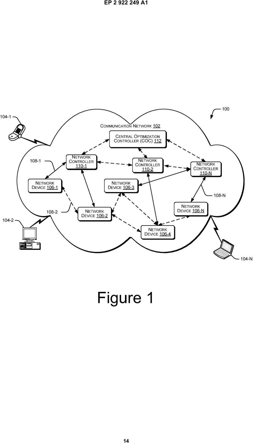
4 Placement of the controllers may be defined as mapping of controller on network devices, such as network switch in order to achieve a uniform load over the network, maximum utilization of the controllers, and minimum delay of control resolution. [0013] According to an implementation of the present subject matter, the communication network may be implemented based on SDN architecture. In one implementation, the optimum number of controller(s) is determined based on the load on the communication network. Since the load on a communication network is a function of time and changes dynamically, the number of controllers to support the load may also change dynamically. Providing optimal number of controllers may include addition or deletion of controllers dynamically. Accordingly, in one implementation of the present subject matter, network controllers may be dynamically added or deleted in the communication network, such as a SDN. Further, in one embodiment, the placement of the network controllers in the control plane may be dynamically varied. [0014] In one embodiment of the present subject matter, the optimization of the number of the controllers and their respective placement may be determined in accordance with a non-zero sum game based network control plane optimization operation. In the non-zero sum game based network control plane optimization operation, hereinafter referred to as control plane optimization operation; each network controller in the communication network computes its self payoff value. The self payoff value is indicative of whether the controller is optimally utilized, underutilized or overutilized. [00] In one implementation, any controller of the communication network which is underutilized and has a capacity to take over more load, may be considered as a greedy controller. Based on the control plane optimization operation, the greedy controller may increase its utilization by sharing load of one or more neighboring controllers. However, in case the controller is significantly underutilized, it may transfer its existing load to one or more neighboring greedy controllers and enter an inactive mode. This approach not only enables equal distribution of load across the various controllers but also ensures that the controllers that have a significantly low utilization are no longer active, thus allowing optimization of the operational cost of the communication network. [0016] In another embodiment, an over-utilized controller may off-load some of its load to one or more neighboring controllers to balance its load. For example, the load may be off-loaded to a neighboring controller that is underutilized. In one embodiment, in case the over-utilized controller is unable to off-load it load to a neighboring controller or is facing excessive load in spite of the off-loading, the overutilized controller may generate a request for activation of an additional controller in the communication network. This, again, ensures equal distribution of load across the various controllers. Also, instances where additional controllers may have to be added in the communication network are promptly identified such that there is no loss of QoS. Activation of the additional controller only at such instances ensures optimization of the operational cost of the communication network. [0017] The control plane optimization operation is carried out by each of the controllers in the communication network. The decision to add or delete network controllers to the communication network is not taken by a centralized control entity but is rather distributed across the various controllers of the communication network. Thus, the performance of the communication network is unaffected by any delay or failure in functioning of the centralized control entity. Further, the systems and methods for control plane optimization as described in accordance with various embodiments of the present subject matter are backward compatible and may also be implemented in legacy communication networks. Furthermore, the systems and methods for control plane optimization described herein are independent of the topology of the communication network. Additionally, the systems and methods for control plane optimization provide a scalable solution for network control plane optimization that may be implemented in any communication network irrespective of the size of the communication network or the amount of load that the communication network handles. [0018] The following disclosure describes systems and methods for control plane optimization in a communication network. It should be noted that the description merely illustrates the principles of the present subject matter. It will thus be appreciated that those skilled in the art will be able to devise various arrangements that, although not explicitly described herein, embody the principles of the present subject matter and are included within its scope. Furthermore, all examples recited herein are principally intended expressly to be only for pedagogical purposes to aid the reader in understanding the principles of the present subject matter and the concepts contributed by the inventor(s) to furthering the art, and are to be construed as being without limitation to such specifically recited examples and conditions. Moreover, all statements herein reciting principles, aspects, and embodiments of the present subject matter, as well as specific examples thereof, are intended to encompass equivalents thereof. [0019] While aspects of the described system and method can be implemented in any number of different computing systems, environments, and/or configurations, embodiments for the information extraction system are described in the context of the following system(s) and method(s). [00] Figure 1 illustrates a network environment implementing a system 0 for control plane optimization in communication network 2, such as a software defined network (SDN), according to an implementation of the present subject matter. In one implementation, the communication network 2 can be a public network, including multiple computing devices 4-1, N, individually and commonly referred to as computing device(s) 4 hereinafter. The computing devices 4, such as personal computers, laptops, various servers, such as blade servers, and other computing devices connected to the communication network 2 to communicate with each other. In another imple- 4

5 mentation, the communication network 2 can be a private network with a limited number of computing devices 4, such as personal computers, servers, laptops, and/or communication devices, such as PDAs, tablets, mobile phones and smart phones connected to the communication network 2 to communicate with each other. [0021] The network environment allows the computing devices 4 to transmit and receive data to and from each other. The computing devices 4 may belong to an end user, such as an individual, a service provider, an organization or an enterprise. The network environment may be understood as a public or a private network system, implementing the system 0 for control plane optimization of the communication network 2 over which the computing devices 4 may communicate with each other. [0022] The communication network 2 may be a wireless network, wired network, or a combination thereof. The communication network 2 can be a combination of individual networks, interconnected with each other and functioning as a single large network, for example, the Internet or an intranet. The communication network 2 may be any public or private network, including a local area network (LAN), a wide area network (WAN), the Internet, an intranet, a peer to peer network, and a virtual private network (VPN). According to an implementation of the present subject matter, the communication network 2 may be a software defined network. Further, embodiments of the present subject matter, the concepts of SDN may be extended to non-sdn networks also. [0023] In an implementation, the communication network 2 may include a plurality of network devices 6-1, 6-2, 6-3,..., 6-N, individually and commonly referred to as network device(s) 6 hereinafter. The network device 6 may be any network hardware device, such as network switch, simple forwarders, routers, gateways, network bridges, and hubs for mediation of data in the communication network 2. Further, a network device 6 may be hybrid network device, such as multilayer switches, proxy servers, or firewalls. The network device 6 may be utilized for communication process through the communication network 2. The network devices 6 may communicate with other network devices 6 of the communication network 2 based on communication links 8. [0024] The communication network 2 may further include a plurality of network controllers 1-1, 1-2,..., 1-N, individually and commonly referred to as controller(s) 1 hereinafter. The controller(s) 1 may be employed on a control plane of a communication network 2 and may manage the flow control of the communication network 2. The controller(s) 1 may receive data from the network devices 6 employed on a data plane of the communication network 2. Further, the controller(s) 1 may obtain a forwarding path for the requests coming from networking devices 6 and configures the networking devices 6 such that networking devices 6 may forward data to other network devices 6 or to a computing device 4-1, N. The controller(s) 1 may be a virtual controller or a physical controller. [002] In one embodiment of the present subject matter, the system 0 determines an optimum number of controller(s) 1 for the communication network 2 based on the load on the communication network 2. In one embodiment, the system 0 performs a non-zero sum game based network control plane optimization operation, interchangeably referred to as control plane optimization operation, to determine the optimum number of controller(s) 1 for the communication network 2. The control plane optimization operation has been explained in details later in this specification. [0026] In accordance with one implementation of the present subject matter, the system 0 includes a central optimization controller (COC) 112 in the communication network 2. In another embodiment of the present subject matter, the COC 112 may be a controller 1 of the communication network 2, assigned to work as COC 112. The COC 112 may optimize the number of controllers 1 in the communication network 2. The COC 112 may be communicatively coupled to the controllers 1 through communication link(s) 8-1, 8-2,..., 8-N. The COC 112 may receive requests from one or more of the ccontrollers 1 for activation or deactivation of additional controllers in the communication network 2. Based on factors, such as a current traffic profile of the controller that sends the request, the network load and quality of service parameters, the COC 112 may allow or refuse the request for activation or deactivation of virtual controllers. [0027] Activation of an additional network controller may include addition of a virtual network controller or invoking an existing dormant physical network controller. Deactivating a network controller may include deleting a virtual controller or putting an active physical controller in a dormant mode. In one example, controllers 1 may run on virtual machines. In such a network configuration, the COC 112 may provide for logical addition and deletion of the controllers 1 in the communication network 2. Logical addition and deletion of controllers 1 may be achieved through the virtual machines running the controllers 1. For instance, each controller 1 runs on a separate virtual machine. The capacity of each virtual machine, such as number of cores or CPUs, memory, disk, may be assigned dynamically. In another example, where the network configuration includes physical network controllers, the physical controllers may be dynamically invoked from a dormant mode or put in a dormant mode. The dormant mode may be a sleep mode or a switch-off mode. The COC 112 may determine to put a physical network controller on either mode based on factors, such as time or traffic profile variation of the communication network 2. [0028] To explain, the functioning of the COC 112 to optimize the number of controllers 1 in the communication network 2, the number of controllers 1 in the communication network 2 may be represented by k, wherein the value of k may vary dynamically. At any instant, the value of k controllers 1 may be within the range of k1 and k2,
![[0021] The network environment allows the computing devices 4 to transmit and receive data to and from each other.](/docs-images/44/14765987/images/page_5.jpg "The computing devices 4 may belong to an end user, such as an individual, a service provider, an organization or an enterprise.")
6 such that k1 k k2, where k1 may be the minimum number of controller(s) 1 and k2 may be the maximum number of controllers 1 in the communication network 2. In the worst case, k1 = 1 and k2 = M, where M may be the number of network devices 6 in the communication network 2. In one embodiment, the optimized number of controllers 1, i.e., the value of k may be determined based on non-zero sum game based control plane optimization operation and k1 and k2 may be obtained from the statistics of the network load change. [0029] Further, based on the control plane optimization operation, the system 0 not only provides the optimum number of controller(s) 1 at a given instance of time but also indicates an optimum placement of the respective controller(s) 1 such that delay and utilization of each of the controller(s) 1 is balanced. In this context, determining the placement of a controller 1 may be understood as ascertaining a number of network devices that may be managed by the controller 1 for a given time and identification of such network devices, such that at the load between the various controllers 1 is balanced. [00] Placements of controllers 1 may be explained referring to Figure 1 that depicts the controllers 1 in the communication network 2 to be communicatively coupled with at least one of the network device(s) 6 through communication links 8-1, 8-2,..., 8-N. Each controller 1 may run in a master-slave mode. Accordingly, the controller 1 may be master for a set of network devices 6 and may be a slave for another set of network devices 6 that may be controlled by another master controller 1. A controller 1 would be master for a network device 6, such as a switch, if the switch refers to the controller 1 for a flow table update and routing. Both master and slave controllers 1 may communicate with each other based on inter-sdn communication protocol. Further, in one embodiment of the present subject matter, the master and slave controllers 1 may be interchangeable based on the load in the communication network 2. Change in the number of controllers 1 and/or change in placement of the existing controllers 1 may result in change of state of master or slave controller 1. The control plane optimization operation to determine that change in number and placement of controller(s) may be based on optimization parameters as follows: where f is a non-linear function of the number of active controllers 1 and cost associated with the number of active controllers 1, k represents the number of active controllers 1, c represents the capital and operational expenditure associated with implementation of the communication network 2, U i represents the utilization of i th controller, Δt i represents the delay associated with i th controller, Δt th represents a pre-defined threshold value for delay constraint of i th controller, and U th represents a pre-defined threshold value of utilization for i th controller. As load on the communication network 2 varies, equation 2 may be solved such that one or more additional controllers 1 may be added or invoked to active state, or an existing controller may be deleted or put in a dormant state. Solution of equation 2 may be obtained by designing a non-zero sum game, in which each controller 1 performs the game independently and may take their decisions independently. Since the load on the network is dynamic, obtaining an optimal solution of equation 2 applicable for load conditions may not possible. Hence, use of non-zero sum game may be appropriate. [0031] As the load on the communication network 2 changes, utilization of the controllers 1 also change. Each controller 1 performs the non-zero sum game based control plane optimization operation to maximize its utilization. Each controller 1 obtains peer information from one or more neighbouring controller 1. Further, each controller 1 computes its payload which indicates whether the controller 1 is optimally utilized, underutilized or overutilized. Based on the payload, the controllers 1 manage their load and may send controller deletion message(s), or the controller addition message(s) to the COC 112. Further, based on the payload, an overutilized controller 1 may transfer its excess load to a neighbouring greedy controller 1 while an underutilized controller 1 may take over additional load from one or more neighbouring controller 1. In this context, load of a controller 1 may be based on the number of network devices 6 that may be managed by the controller 1 at any given instance of time and the volume of traffic 6
![[0029] Further, based on the control plane optimization operation, the system 0 not only provides the optimum number of controller(s) 1 at a given instance of time but also indicates an optimum](/docs-images/44/14765987/images/page_6.jpg "placement of the respective controller(s) 1 such that delay and utilization of each of the controller(s) 1 is balanced.")
7 2 3 each of these network devices 6 may be handling. Further, any controller 1 in the communication network 2 having capacity to take more load may be considered as a greedy controller. [0032] Figure 2 illustrates a network controller 1, according to an implementation of the present subject matter. According to an implementation, the controller 1 may include processor(s) 2, interface(s) 4, and memory 6 coupled to the processor(s) 2. The processor(s) 2 of the controller 1 may be implemented as one or more microprocessors, microcomputers, microcontrollers, digital signal processors, central processing units, state machines, logic circuitries, and/or any devices that manipulate signals based on operational instructions. Among other capabilities, the processor(s) 2 may be configured to fetch and execute computer-readable instructions stored in the memory 6. [0033] Further, the interface(s) 4 of the controller 1 may include a variety of software and hardware interfaces that allow the controller 1 to interact with other entities of the communication network 2, or with each other. For example, the interface(s) 4 may enable the controller 1 to communicate with network devices 6 and other devices, such as web servers and external repositories. The interface(s) 4 may also facilitate multiple communications within a wide variety of networks and protocol types, including wired networks, for example, LAN, cable, etc., and wireless networks, such as WLAN, cellular, or satellite. For the purpose, the interface(s) 4 may include one or more ports. [0034] The memory 6 may include any computer-readable medium known in the art including, for example, volatile memory, such as static random access memory (SRAM), and dynamic random access memory (DRAM), and/or nonvolatile memory, such as read only memory (ROM), erasable programmable ROM, flash memories, hard disks, optical disks, and magnetic tapes. Further, the controller 1 may include module(s) 8 and data 2. The module(s) 8 include, for example, a communication module 212, a control module 214, and other module(s) 218. [003] The data 2 may include network device data 2, and other data 224. The device data 2 may further include peer information 222. The other data 224 amongst other things, may serve as a repository for storing data that is processed, received, or generated as a result of the execution of one or more modules in the module(s) 8. [0036] According to an implementation, the communication module 212 of the controller 1 may communicate with several network devices 6 of the communication network 2. Further, the communication module 212 may communicate with neighbouring controllers in the communication network 2. Such communication may be based on inter- SDN communication protocols. Communication of the controller 1 with neighbouring controllers 1 may include request for peer information comprising routing updates, self payoff value, or may include information messages, such as offloading message, and state change message. The communication module 212 may communicate with the module(s) 8 of the controller 1 for exchange of controller messages. In one embodiment, the communication module 212 may communicate the control messages to the neighbouring controller(s) 1 at a time instance of routing updates. [0037] The network controller 1 includes the control module 214 to determine a traffic profile variation, compute a self payoff value, and update the routing tables. The configuration information of the controller 1, such as routing table may be stored in the network device data 2. Further, the peer information received by the communication module 212 from the neighbouring controllers 1 may be stored in the peer information 222. [0038] In accordance with one implementation of the present subject matter, the control module 214 determines a traffic profile variation in the communication network 2. The control module 214 may receive network traffic and load information from time to time from the communication module 212. The control module 214 analyses the traffic information received at various instances of time and determines a traffic variation profile. The traffic profile variation may be indicative of changes in a current traffic profile of the controller 1 and the neighbouring controller(s) 1 with respect to a previous traffic profile. [0039] The control module further computes a self payoff value for the controller 1. The self payoff value, also referred to as payoff, may be determined based on equation [00] where, f i represents the self payoff value of a i th controller, λ i represents a non linear function or a constant for i th controller related to the usage of the controller, U i represents the utilization of i th controller, U th represents a predefined threshold value of utilization for i th controller, δ i represents a nonlinear function or a constant for delay payoff computation for a controller i related to the delay experienced by it, Δt th represents a pre-defined threshold value for delay constraint of i th controller, and Δt i represents the delay constraint for i th controller. The values of λ i, U i, U th, δ i, δt th, Δt ti and the self payoff value may also be stored in the network device data 2. [0041] In accordance with one implementation of the present subject matter, the control module 214 includes an optimization module 216 for optimization of the controller(s) 1 in the communication network 2. The optimization module 216 performs the control plane optimization operation with the neighbouring controller(s). Based on the solution achieved by performing the operation, the optimization module 216 may decide the process to be executed to achieve maximum utilization. In one example, the optimization module 216 of an overutilized controller 1 may offload several 7
 2 of the controller 1 may be implemented as one or more microprocessors, microcomputers, microcontrollers, digital signal processors, central processing units, state machines, logic")
8 network device(s) 6 based on the solution of the control plane optimization operation. In another example, the optimization module 216 of an underutilized controller 1, may master several network device(s) 6 of the communication network 2, based on the solution of the control plane optimization operation. [0042] In an example, based on the non-zero sum game based control plane optimization operation when the controller 1 transfers control of some of the network devices 6 that it may be managing to a neighbouring controller 1 or when the controller 1 acquires control of additional network devices 6 from one or more neighbouring controllers 1, a change in placement of the controller 1 occurs. The communication module 212 may communicate control messages to inform such change in placements or transfer of control to one or more neighbouring controllers 1. In one embodiment, the communication module 212 may also communicate the control messages to the COC 112. Also, in cases where, based on the non-zero sum game based control plane optimization operation, if a decision to activate or deactivate a controller 1 is taken, the communication module 212 may further communicate the request to the COC 112. [0043] In one implementation of the present subject matter, the various control messages may be communicated asynchronously. In one more implementation of the present subject matter the communication module 212 communicates with the neighbouring controllers in an asynchronous manner to obtain the peer information. Such asynchronous communication wherein not all controllers 1 talk to each other at the same time ensures that, at any given instance of time, the volume of control messages being exchanged between the various controllers 1 of the communication network 2 is within acceptable limits and that the control messages do not overload the controllers 1. [0044] Figure 3 illustrates a central optimization controller (COC) 112, according to an implementation of the present subject matter. According to an implementation, the COC 112 may include processor(s) 2, interface(s) 4, and memory 6 coupled to the processor(s) 2. The processor(s) 2 of the COC 112 may be implemented as one or more microprocessors, microcomputers, microcontrollers, digital signal processors, central processing units, state machines, logic circuitries, and/or any devices that manipulate signals based on operational instructions. Among other capabilities, the processor(s) 2 may be configured to fetch and execute computer-readable instructions stored in the memory 6. [004] Further, the interface(s) 4 of the COC 112 may include a variety of software and hardware interfaces that allow the COC 112 to interact with other entities of the communication network 2, or with each other. For example, the interface(s) 4 may enable the COC 112 to communicate with network devices 6 and other devices, such as web servers and external repositories. The interface(s) 4 may also facilitate multiple communications within a wide variety of networks and protocol types, including wired networks, for example, LAN, cable, etc., and wireless networks, such as WLAN, cellular, or satellite. For the purpose, the interface(s) 4 may include one or more ports. [0046] The memory 6 may include any computer-readable medium known in the art including, for example, volatile memory, such as static random access memory (SRAM), and dynamic random access memory (DRAM), and/or nonvolatile memory, such as read only memory (ROM), erasable programmable ROM, flash memories, hard disks, optical disks, and magnetic tapes. Further, the COC 112 may include module(s) 8 and data 3. The module(s) 8 include, for example, a communication module 312, a controller optimization module 314, and other module(s) 316. [0047] The data 3 may include controller optimization data 318, and other data 3. The other data 3 amongst other things, may serve as a repository for storing data that is processed, received, or generated as a result of the execution of one or more modules in the module(s) 8. [0048] According to an implementation, the communication module 312 of the COC 112 may communicate with several controller(s) 1 of the communication network 2. The communication module 312 may receive request from the controllers 1 for optimization of the number of controllers 1 in the communication network 2. The request may include, request for activation of a new controller 1 in the communication network 2, or request for deactivation of an existing controller 1 from the communication network 2. [0049] The COC 112 includes the controller optimization module 314 for execution of the request received by the communication module 312. The controller optimization module 314 may activate an additional controller in the communication network 2 or may deactivate an existing controller in the communication network 2, based on the request received. Information related to controllers 1, such as the number of controllers 1 in the communication network 2, status of controllers 1, and number of controllers 1 in sleep or switched-off mode, may be stored as the controller optimization data 318. [000] Although in the above described embodiment, the COC 112 deactivates existing controllers based on received requests, in other embodiments, deactivation of a controller 1 in the communication network 2 may be executed by the controllers 1 themselves. For example, a controller 1 may perform the control plane optimization operation and upon determining that it is substantially underutilized, the controller 1 may execute a process to enter the inactive mode. Thus, the controller 1 may offload the associated network devices 6 and deactivates itself without intervention of the COC 112. For example, an inactive virtual network controller may be deleted while an inactive physical network controller may become dormant. Such inactive physical controllers may be considered to be in a dormant mode which can be realized by either switching off the controller 1 or by keeping the controller 1 in an idle state with limited 8

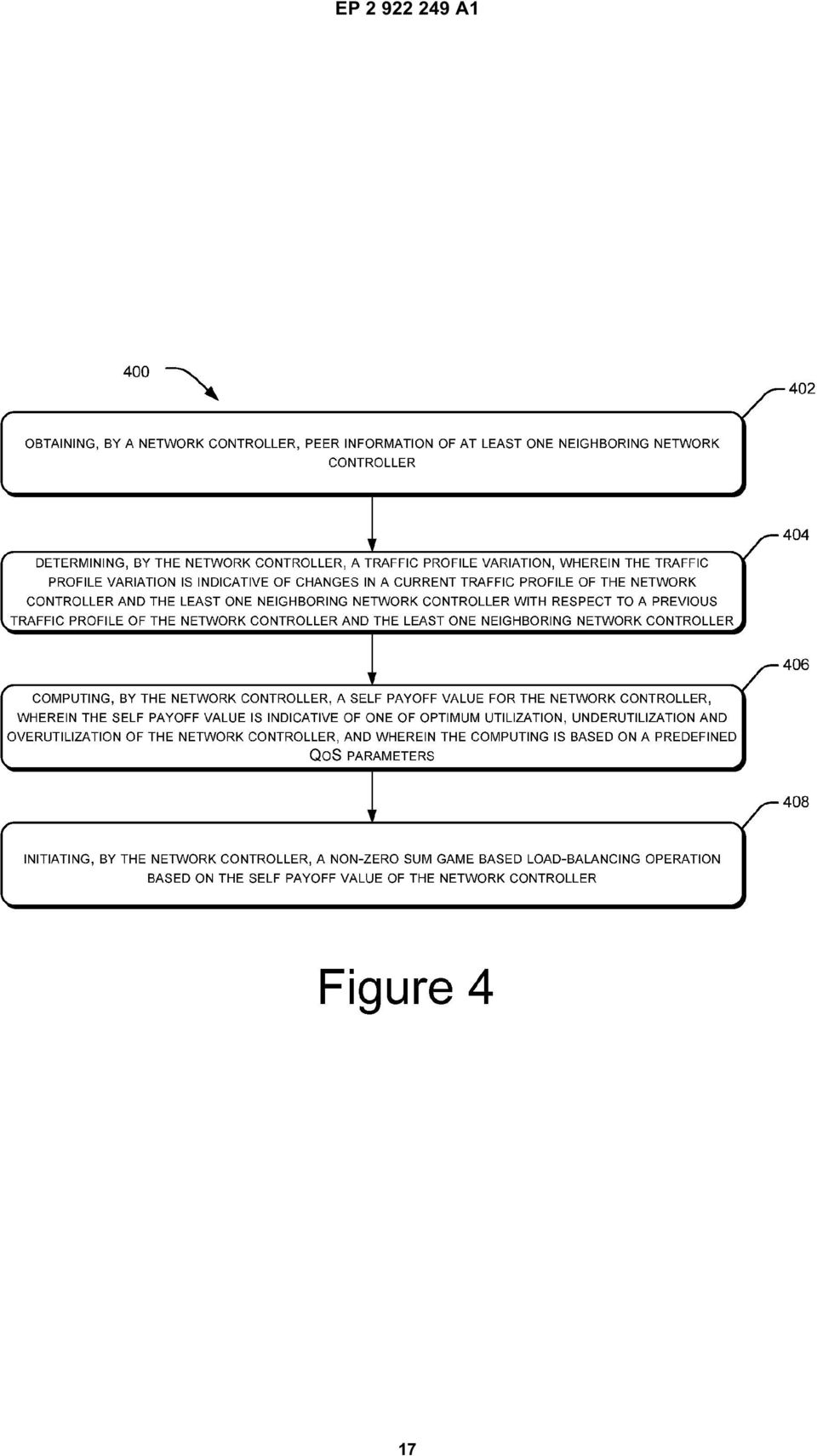
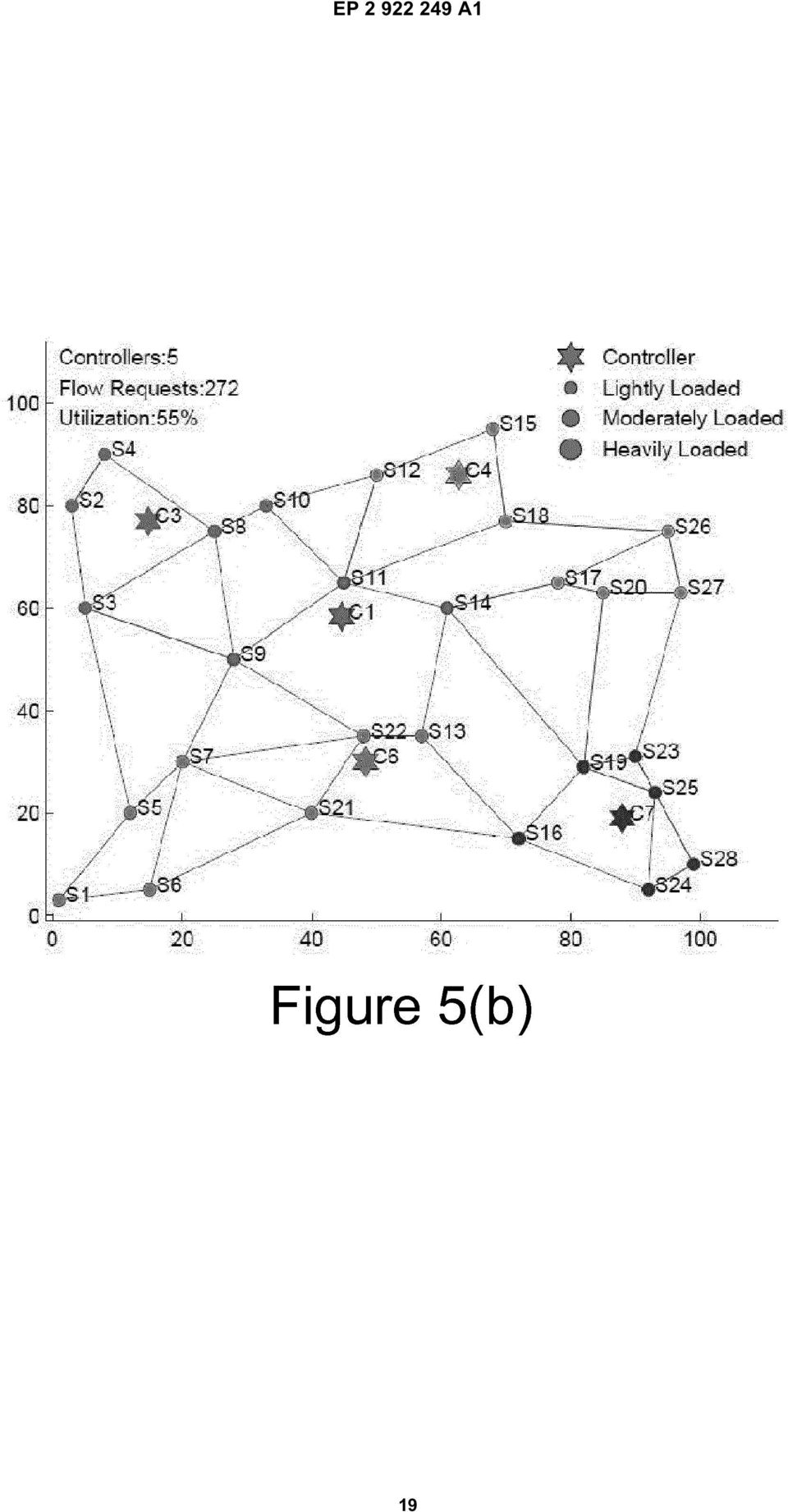
9 operations, such as sleep mode. The controller 1 which is in sleep mode can be activated and made fully operational by control message received from the COC 112 or any other controller 1. Change of state, i.e., active to inactive and vice versa may be stored in the data of the COC 112 and in the data of all neighbouring controllers 1. [001] Figure 4 illustrates a control plane optimization method, according to an implementation of the present subject matter. The method 0 may be described in the general context of computer executable instructions. Generally, computer executable instructions can include routines, programs, objects, components, data structures, procedures, modules, functions, etc., that perform particular functions or implement particular abstract data types. The method 0 may also be practiced in a distributed computing environment where functions are performed by remote processing devices that are linked through a communications network. In a distributed computing environment, computer executable instructions may be located in either a local or a remote computer storage media, including memory storage devices. [002] The order in which the method 0 is described is not intended to be construed as a limitation, and any number of the described method blocks can be combined in any order to implement the method 0, or alternative methods. Additionally, individual blocks may be deleted from the methods without departing from the spirit and scope of the subject matter described herein. Furthermore, the method 0 can be implemented in any suitable hardware, software, firmware, or combination thereof. [003] Referring to figure 4, at block 2, the method 0 may include obtaining, by a network controller 1, peer information of at least one neighbouring network controller 1. The peer information may be indicative of utilization and delay associated with the performance of the at least one neighbouring network controller 1. [004] At block 4, the method 0 includes determining a traffic profile variation by the network controller 1. The traffic profile variation may be indicative of changes in a current traffic profile of the network controller 1 and the least one neighbouring network controller 1 with respect to a previous traffic profile of the network controller 1 and the least one neighbouring network controller 1. [00] At block 6, the method 0 includes computing a self payoff value for the network controller 1, by the network controller 1. The self payoff value may be indicative of one of optimum utilization, underutilization and overutilization of the network controller 1. Further, as explained previously, the computing of self payoff value may be based on predefined QoS parameters, which may include parameters, such as maximum and minimum utilization threshold values. [006] At block 8, the method 0 includes initiating a non-zero sum game based control plane optimization operation based on the self payoff value, by the network controller 1 and neighbour s payoff values. The non-zero sum game based control plane optimization operation provides for optimizing the number and placement of controllers 1 in the communication network. The control plane optimization operation may include one of activating of at least one additional network controller 1, transferring control of one or more network devices 6 managed by the network controller 1 to a neighbouring network controller 1, deactivating the network controller 1, and transferring control of one or more additional network devices 6 to the network controller 1. [007] Figure (a) illustrates an SDN topology implementing the non-zero sum game based control plane optimization operation, according to an implementation of the present subject matter. The figure illustrates the SDN topology with 7 active controllers 1 (C1, C2,..., C7) in the communication network 2 represented by a star. The figure further illustrates 28 network devices 6 represented by circles. For the ease of explanation, the network devices 6 may be assumed to be switches (S1, S2,..., S28). The switches may be categorized in three categories based on the loads, such as lightly loaded, moderately loaded, and heavily loaded. In the example illustrated in the figure, the switches are uniformly loaded. Further, the figure illustrates communication links 8 for sharing of information amongst switches. According to the example illustrated in the figure, 323 flow requests may be severed by the 7 active controllers 1 and 47% utilization of the controllers 1 may be achieved in the illustrated example. In accordance with one embodiment of the present subject matter, the configuration of the communication network 2 may be modified, i.e., the number of placement of the controllers 1 may be changed to achieve improved utilization of the controllers 1. In one example, the SDN topology as depicted in Figure (a) may be modified to the SDN topology as depicted in Figure (b) to achieve improved utilization of the controllers 1 since 47% utilization of the controllers 1 as depicted in the example of Figure (a) may be considered low. [008] Figure (b) illustrates an SDN topology implementing the non-zero sum game based control plane optimization operation for a decreasing load, according to an implementation of the present subject matter. The network topology illustrates the same topology as of figure (a), with same number of network devices as 28 switches but with lesser number of flow requests. The topology serves 272 flow requests with active controllers and achieving a utilization of %. [009] According to an implementation of the present subject matter, each controller 1 as illustrated in the figures (a) and (b) computes a self payoff value and runs the load-optimization process at several instances of time to achieve maximum utilization. For example, controller C4 may obtain peer information of neighbouring controllers C1, C2, and C3 and information of switches of such controllers. The controller C4 determines the change in the traffic profile based on the current traffic profile and previously received traffic profile. In such situation, where the number of flow requests decreases, the controller performs the control plane optimization operation to maximize utilization. Hence, the controller 9
![[001] Figure 4 illustrates a control plane optimization method, according to an implementation of the present subject matter.](/docs-images/44/14765987/images/page_9.jpg "The method 0 may be described in the general context of computer executable instructions.")
10 C4 compares its self payoff value with the minimum threshold payoff value and maximum threshold payoff value to determine underutilization or overutilization of the controller. Based on the information about utilization of the controller, each controller performs the control plane optimization operation along with one or more neighbouring controllers. [0060] In the illustrated example, the process of performing the control plane optimization operation by each of the controllers in the network results in increased utilization by deletion of 2 controllers C2, and C. The switches mastered by controllers C2 and C may be offloaded to other active controllers before deletion. For example, the switches S17, S18, S26, and S27 originally mastered by controller C2, may be mastered by controller C4 on deletion of controller C2. Thus, controller C4 originally mastering 3 switches, may master 7 switches. Similarly, the controller C may be deleted for achieving maximum utilization of controllers. The switches S1, S, S6, and S7 originally mastered by controller C may be mastered by controller C6 on deletion of controller C. Thus, the controller C6 originally mastering 3 switches may master 7 switches. In the above described example, decision of deletion of controllers results an increase in utilization of controllers. The utilization of 47%, as illustrated in Figure (a) increases to % on deletion of two controllers, as illustrated in Figure (b). Such decision of deletion of controllers further results in decrease of operational expenditure of the communication network 2. Optimization of number of controllers for a changing network traffic is further illustrated based on figures 6(a), 6(b), 7(a), and 7(b) [0061] Figure 6(a) illustrates an SDN topology implementing the non-zero sum game based control plane optimization operation, according to an implementation of the present subject matter. The figure illustrates a SDN topology with active controllers (C2, C3, C, C6, and C7) in the network represented by a star. The figure further illustrates 28 network devices 6 represented by circles. The network devices 6 may be assumed to be switches (S1, S2... S28). The switches may be categorized in three categories based on the loads, such as lightly loaded, moderately loaded, and heavily loaded. Such categories may be represented virtually based on the size of the circle in the figure. Lightly loaded switches may be represented by a circle with a small diameter; moderately loaded switches may be represented by a circle of diameter larger than the diameter of the lightly loaded switch; while the heavily loaded switch may be represented by a circle of largest diameter among the circles of three categories of switch loads. Further, the figure illustrates communication links 8 for sharing of information amongst switches. [0062] According to the example illustrated in the figure, 367 flow requests may be served by the active controllers and 74% utilization of the controllers may be achieved in the illustrated example. The figure further illustrates non-uniform distribution of load over the switches. In accordance with one embodiment of the present subject matter, the configuration of the communication network may be modified, i.e., the number of controllers and mapping of the controllers to the switches may be changed to achieve optimum utilization of the controllers based on the network load. In one example, the SDN topology as depicted in Figure 6(a) may be modified to the SDN topology as depicted in Figure 6(b) to achieve optimum utilization of the controllers. [0063] Figure 6(b) illustrates an SDN topology implementing the non-zero sum game based control plane optimization operation for an increasing network load, according to an implementation of the present subject matter. The network topology illustrates a similar topology as of figure 6(a), with same number of network devices as 28 switches but with increased number of flow requests as 416. The topology serves 416 flow requests with 6 active controllers and achieving a utilization of 70%. [0064] According to the illustrated example, on an increase in the number of flow requests, the load on the switches S1, S2, S3, S4, S7, S9, S, S16, S17, S22, and S24 increases, the load on S decreases, while the load on other switches does not change. The network load on switches causes an imbalance of the load distribution on the active controllers as depicted in figure 6(a). As the traffic profile of the controllers change, each controller performs the control plane optimization operation to optimize the load. Based on the solutions of the control plane optimization operation performed by the controllers, a message for activation of an additional controller may be sent to the COC 112. The COC 112 activates the additional controller C4 in the network. The controllers, based on the results of the control plane optimization operation reallocate the switches mastered by each controller. Thus, the new controller C4 masters switches S1, S, and S6 offloaded by controller C7. Since the total load on the controller C7 reduces on offloading of switches to C4, the controller C7 performs the control plane optimization operation with C2 and masters switches S16 and S19. Further, as the controller C2 also performs the control plane optimization operation with its neighbouring controllers, controller C2 masters switch S27 offloaded by controller C3. Thus, as illustrated in the example, an increase in the number of flow requests may be served by increasing the number of controllers in the communication network. [006] Figure 7(a) illustrates an SDN topology implementing the non-zero sum game based control plane optimization operation, according to an implementation of the present subject matter. The figure illustrates a SDN topology with 6 active controllers (C2, C3,..., C7) in the communication network represented by a star. The figure further illustrates 28 network devices represented by circles. The network devices 6 may be assumed to be switches (S1, S2,..., S28). The switches may be categorized in three categories based on the loads, such as lightly loaded, moderately loaded, and heavily loaded. Such categories may be represented virtually based on the size of the circle in the figure. Lightly loaded switches may be represented by a circle with a small diameter; moderately loaded switches may be represented by a circle of diameter larger than the diameter of the lightly loaded switch; while the heavily loaded switch may be
![[0060] In the illustrated example, the process of performing the control plane optimization operation by each of the controllers in the network results in increased utilization by deletion of 2](/docs-images/44/14765987/images/page_10.jpg "controllers C2, and C. The switches mastered by controllers C2 and C may be offloaded to other active controllers before deletion.")
11 2 represented by a circle of largest diameter among the circles of three categories of switch loads. Further, the figure illustrates communication links 8 for sharing of information amongst switches. [0066] According to the example illustrated in the figure, 442 flow requests may be severed by the 6 active controllers and 74% utilization of the controllers may be achieved in the illustrated example. The figure further illustrates non-uniform distribution of load over the switches. In accordance with one embodiment of the present subject matter, the configuration of the communication network 2 may be modified, i.e., the number of controllers and the mapping of the controllers to the switches may be changed to achieve optimum utilization of the controllers based on the network load. In one example, the SDN topology as depicted in Figure 7(a) may be modified to the SDN topology as depicted in Figure 7(b) to achieve optimum utilization of the controllers. [0067] Figure 7(b) illustrates an SDN topology implementing the non-zero sum game based control plane optimization operation for a change in network load, according to an implementation of the present subject matter. The network topology illustrates a similar topology as of figure 7(a), with same number of network devices as 28 switches but with decreased number of flow requests as 438. The topology serves 438 flow requests with 6 active controllers and achieving a utilization of 73%. [0068] According to the illustrated example, on a decrease in the number of flow requests, the load on the switches S1, S3, S6, S 13, S, and S23 increases, load on switches S2, S7, S9, S, S11 S12, S14, S21, S24, S2, and S27 decreases, while the load on the other switches does not change. The network load on switches causes an imbalance of the load distribution on the 6 active controllers as depicted in figure 7(a). As the traffic profile for the controllers change, each controller performs the control plane optimization operation to optimize the load. As illustrated, since the decrease in the number of flow requests is small, deactivation of a controller may not provide an optimized solution. Thus, based on the results of the control plane optimization operation performed by the controllers, the controllers reallocate the switches to optimize the load distribution. Switches S7 and S9 are mastered by controller C on offloading by controller C4, based on the control plane optimization operation performed by controller C4 with controller C. Thus, as illustrated in the example, a decrease in the number of flow requests is optimized based on control plane optimization operation to achieve optimum utilization of the controllers. [0069] Although embodiments for methods and systems for controller optimization in communication networks have been described in a language specific to structural features and/or methods, it is to be understood that the invention is not necessarily limited to the specific features or methods described. Rather, the specific features and methods are disclosed as exemplary embodiments for load optimization in software defined networks. Claims 3 1. A method for optimization of a control plane comprising network controllers in a communication network, the method comprising: 4 0 obtaining, by a network controller, peer information of at least one neighbouring network controller, wherein the peer information is indicative of utilization and delay associated with performance of the at least one neighbouring network controller; determining, by the network controller, a traffic profile variation, wherein the traffic profile variation is indicative of changes in a current traffic profile of the network controller and the at least one neighbouring network controller with respect to a previous traffic profile of the network controller and the at least one neighbouring network controller; computing, by the network controller, a self payoff value for the network controller, wherein the self payoff value is indicative of one of optimum utilization, underutilization and overutilization of the network controller, and wherein the computing is based on predefined QoS parameters; and initiating, by the network controller, a non-zero sum game based network control plane optimization operation based on the self payoff value and the traffic profile of at least one neighbouring network controller, wherein the non-zero sum game based network control plane optimization operation comprises one of: activating at least one additional network controller, transferring control of one or more network devices managed by the network controller to the at least one neighbouring network controller, deactivating the network controller, and transferring control of one or more network devices managed by the at least one neighbouring network controller to the network controller. 2. The method as claimed in claim 1, wherein, for the self payoff value indicative of overutilization of the network controller, the non-zero sum game based network control plane optimization operation comprises: 11

12 generating a request for activation of the at least one additional network controller; receiving an indication of activation of the at least one additional network controller; transferring control of one or more network devices managed by the network controller to the at least one additional network controller; and generating a control message to inform the transferring to the at least one neighbouring network controller. 3. The method as claimed in claim 2, wherein the activation of the at least one additional network controller comprises one of adding a virtual network controller and invoking a dormant physical network controller. 4. The method as claimed in claim 1, wherein, for the self payoff value indicative of overutilization of the network controller, the non-zero sum game based network control plane optimization operation comprises: 2 identifying a greedy controller from amongst at least one neighbouring network controller, to undertake more load; requesting the greedy controller to accept control of one or more network devices managed by the network controller; receiving a response from the greedy controller; transferring control of one or more network devices managed by the network controller to the greedy controller based on the response; and generating a control message to inform the transferring to the at least one neighbouring network controller.. The method as claimed in claim 1, wherein, for the self payoff value indicative of underutilization of the network controller, the non-zero sum game based network control plane optimization operation, comprises deactivating the network controller. 6. The method as claimed in claim, wherein the deactivating comprises one of deleting a virtual network controller and putting a active physical network controller in a dormant mode, and wherein putting the active physical network controller in the dormant mode further comprises one of switching off the network controller and putting the active physical network controller in a sleep mode. 7. The method as claimed in claim 1, wherein, for the self payoff value indicative of underutilization of the network controller, the non-zero sum game based network control plane optimization operation comprises: 3 identifying a greedy controller from amongst at least one neighbouring network controller, to undertake more load; off-loading control of one or more network devices managed by the network controller to the greedy controller; generating a control message to inform the off-loading to the at least one neighbouring network controller; and initiating a dormant mode for the network controller. 8. A network controller (1) comprising: 4 0 a processor (2); a communication module (212) coupled to the processor (2) to obtain peer information of at least one neighbouring network controller (1), wherein the peer information is indicative of utilization and delay associated with performance of the at least one neighbouring network controller (1); a control module (214) coupled to the processor (2) to: determine a traffic profile variation, wherein the traffic profile variation is indicative of changes in a current traffic profile of the network controller (1) and the at least one neighbouring network controller (1) with respect to a previous traffic profile of the network controller (1) and the at least one neighbouring network controller (1); compute a self payoff value for the network controller (1), wherein the self payoff value is indicative of one of optimum utilization, underutilization and overutilization of the network controller (1), and wherein the computing is based on a predefined QoS parameters; and initiating a non-zero sum game based network control plane optimization operation based on the self payoff value and the traffic profile of the at least one neighbouring network controller, wherein the non-zero sum game based network control plane optimization operation comprises one of: activating at least one additional network controller (1), transferring control of one or more network devices (6) managed by the network controller (1) to the at least one neighbouring network con- 12

13 troller (1), deactivating the network controller (1), and transferring control of one or more network devices (6) managed by the at least one neighbouring network controllers to the network controller (1). 9. The network controller (1) as claimed in claim 8, wherein the communication module (212) communicates control messages to the at least one neighbouring network controller (1), wherein the control messages are indicative of activation of the at least one additional network controller (1), transfer of control of the one or more network devices (6) managed by the network controller (1) to the at least one neighbouring network controller (1), deactivation of the network controller (1), and transfer of control of the one or more network devices (6) managed by the at least one neighbouring network controllers to the network controller (1).. The network controller (1) as claimed in claim 9, wherein the communication module (212) obtains peer information of the at least one neighbouring network controller (1) and communicates the control messages to the at least one neighbouring network controller (1) asynchronously. 11. The network controller (1) as claimed in claim, wherein the communication module (212) communicates the control messages to the at least one neighbouring network controller (1) at a time instance of routing updates. 12. The network controller (1) as claimed in claim 8, wherein the communication module (212) sends a request to a central optimization controller (112) for one of activating the at least one additional network controller (1) and deactivating the network controller (1) The network controller (1) as claimed in claim 8, wherein the control module (214) updates the routing table of the network controller (1). 14. The network controller (1) as claimed in claim 8, wherein the QoS parameters comprise maximum utilization threshold value of the network controller (1), minimum utilization threshold value of the network controller (1), and minimum delay of the control resolution.. A central optimization controller (1) comprising: 3 a processor (2); a communication module (312) coupled to the processor (2) to receive a request, from a network controller (1), for activating at least one additional network controller (1) in a communication network (2); and a controller optimization module (314) coupled to the processor (2) to activate the least one additional network controller (1) in response to the request based on a current traffic profile of the network controller (1), the current traffic profile being indicative of a utilization and delay associated with performance of the network controller (1)
, transfer of control of the one or more network devices (6) managed by the network controller (1) to the at")
14 14
15

16 16

17 17
18 18

19 19
20

TEPZZ 9 Z5A_T EP 2 922 305 A1 (19) (11) EP 2 922 305 A1. (12) EUROPEAN PATENT APPLICATION published in accordance with Art.
 (11) EP 2 922 305 A1. (12) EUROPEAN PATENT APPLICATION published in accordance with Art.") (19) TEPZZ 9 ZA_T (11) EP 2 922 A1 (12) EUROPEAN PATENT APPLICATION published in accordance with Art. 13(4) EPC (43) Date of publication: 23.09.1 Bulletin 1/39 (21) Application number: 1386446.2 (22) Date
(19) TEPZZ 9 ZA_T (11) EP 2 922 A1 (12) EUROPEAN PATENT APPLICATION published in accordance with Art. 13(4) EPC (43) Date of publication: 23.09.1 Bulletin 1/39 (21) Application number: 1386446.2 (22) Date
TEPZZ 94Z968A_T EP 2 940 968 A1 (19) (11) EP 2 940 968 A1 (12) EUROPEAN PATENT APPLICATION. (51) Int Cl.: H04L 29/08 (2006.01)
 (11) EP 2 940 968 A1 (12) EUROPEAN PATENT APPLICATION. (51) Int Cl.: H04L 29/08 (2006.01)") (19) TEPZZ 94Z968A_T (11) EP 2 940 968 A1 (12) EUROPEAN PATENT APPLICATION (43) Date of publication: 04.11.20 Bulletin 20/4 (1) Int Cl.: H04L 29/08 (2006.01) (21) Application number: 1430649.7 (22) Date
(19) TEPZZ 94Z968A_T (11) EP 2 940 968 A1 (12) EUROPEAN PATENT APPLICATION (43) Date of publication: 04.11.20 Bulletin 20/4 (1) Int Cl.: H04L 29/08 (2006.01) (21) Application number: 1430649.7 (22) Date
TEPZZ 6_Z76 A_T EP 2 610 763 A1 (19) (11) EP 2 610 763 A1 (12) EUROPEAN PATENT APPLICATION. (51) Int Cl.:
 (11) EP 2 610 763 A1 (12) EUROPEAN PATENT APPLICATION. (51) Int Cl.:") (19) TEPZZ 6_Z76 A_T (11) EP 2 6 763 A1 (12) EUROPEAN PATENT APPLICATION (43) Date of publication: 03.07.2013 Bulletin 2013/27 (51) Int Cl.: G06F 17/30 (2006.01) (21) Application number: 12192220.7 (22)
(19) TEPZZ 6_Z76 A_T (11) EP 2 6 763 A1 (12) EUROPEAN PATENT APPLICATION (43) Date of publication: 03.07.2013 Bulletin 2013/27 (51) Int Cl.: G06F 17/30 (2006.01) (21) Application number: 12192220.7 (22)
EP 2 455 926 A1 (19) (11) EP 2 455 926 A1 (12) EUROPEAN PATENT APPLICATION. (43) Date of publication: 23.05.2012 Bulletin 2012/21
 (11) EP 2 455 926 A1 (12) EUROPEAN PATENT APPLICATION. (43) Date of publication: 23.05.2012 Bulletin 2012/21") (19) (12) EUROPEAN PATENT APPLICATION (11) EP 2 4 926 A1 (43) Date of publication: 23.0.2012 Bulletin 2012/21 (21) Application number: 11190024.7 (1) Int Cl.: G08B 2/14 (2006.01) G08B 2/00 (2006.01) G0B
(19) (12) EUROPEAN PATENT APPLICATION (11) EP 2 4 926 A1 (43) Date of publication: 23.0.2012 Bulletin 2012/21 (21) Application number: 11190024.7 (1) Int Cl.: G08B 2/14 (2006.01) G08B 2/00 (2006.01) G0B
TEPZZ 69 49A_T EP 2 693 349 A1 (19) (11) EP 2 693 349 A1 (12) EUROPEAN PATENT APPLICATION. (51) Int Cl.: G06F 17/30 (2006.01)
 (11) EP 2 693 349 A1 (12) EUROPEAN PATENT APPLICATION. (51) Int Cl.: G06F 17/30 (2006.01)") (19) TEPZZ 69 49A_T (11) EP 2 693 349 A1 (12) EUROPEAN PATENT APPLICATION (43) Date of publication: 0.02.2014 Bulletin 2014/06 (1) Int Cl.: G06F 17/30 (2006.01) (21) Application number: 13160696.4 (22)
(19) TEPZZ 69 49A_T (11) EP 2 693 349 A1 (12) EUROPEAN PATENT APPLICATION (43) Date of publication: 0.02.2014 Bulletin 2014/06 (1) Int Cl.: G06F 17/30 (2006.01) (21) Application number: 13160696.4 (22)
TEPZZ 87_546A T EP 2 871 546 A2 (19) (11) EP 2 871 546 A2 (12) EUROPEAN PATENT APPLICATION. (51) Int Cl.: G05B 19/05 (2006.01)
 (11) EP 2 871 546 A2 (12) EUROPEAN PATENT APPLICATION. (51) Int Cl.: G05B 19/05 (2006.01)") (19) TEPZZ 87_46A T (11) EP 2 871 46 A2 (12) EUROPEAN PATENT APPLICATION (43) Date of publication: 13.0.1 Bulletin 1/ (1) Int Cl.: G0B 19/0 (06.01) (21) Application number: 14188238.1 (22) Date of filing:
(19) TEPZZ 87_46A T (11) EP 2 871 46 A2 (12) EUROPEAN PATENT APPLICATION (43) Date of publication: 13.0.1 Bulletin 1/ (1) Int Cl.: G0B 19/0 (06.01) (21) Application number: 14188238.1 (22) Date of filing:
TEPZZ 68575_A_T EP 2 685 751 A1 (19) (11) EP 2 685 751 A1. (12) EUROPEAN PATENT APPLICATION published in accordance with Art.
 (11) EP 2 685 751 A1. (12) EUROPEAN PATENT APPLICATION published in accordance with Art.") (19) TEPZZ 687_A_T (11) EP 2 68 71 A1 (12) EUROPEAN PATENT APPLICATION published in accordance with Art. 3(4) EPC (43) Date of publication:.01.14 Bulletin 14/03 (21) Application number: 1278849.6 (22)
(19) TEPZZ 687_A_T (11) EP 2 68 71 A1 (12) EUROPEAN PATENT APPLICATION published in accordance with Art. 3(4) EPC (43) Date of publication:.01.14 Bulletin 14/03 (21) Application number: 1278849.6 (22)
TEPZZ 88_898A_T EP 2 881 898 A1 (19) (11) EP 2 881 898 A1 (12) EUROPEAN PATENT APPLICATION. (51) Int Cl.: G06N 5/04 (2006.01) G06F 17/30 (2006.
 (11) EP 2 881 898 A1 (12) EUROPEAN PATENT APPLICATION. (51) Int Cl.: G06N 5/04 (2006.01) G06F 17/30 (2006.") (19) TEPZZ 88_898A_T (11) EP 2 881 898 A1 (12) EUROPEAN PATENT APPLICATION (43) Date of publication:.06. Bulletin /24 (1) Int Cl.: G06N /04 (06.01) G06F 17/ (06.01) (21) Application number: 136680.3 (22)
(19) TEPZZ 88_898A_T (11) EP 2 881 898 A1 (12) EUROPEAN PATENT APPLICATION (43) Date of publication:.06. Bulletin /24 (1) Int Cl.: G06N /04 (06.01) G06F 17/ (06.01) (21) Application number: 136680.3 (22)
TEPZZ 87657ZA_T EP 2 876 570 A1 (19) (11) EP 2 876 570 A1 (12) EUROPEAN PATENT APPLICATION
 (11) EP 2 876 570 A1 (12) EUROPEAN PATENT APPLICATION") (19) TEPZZ 8767ZA_T (11) EP 2 876 70 A1 (12) EUROPEAN PATENT APPLICATION (43) Date of publication: 27.0.201 Bulletin 201/22 (21) Application number: 14189809.8 (1) Int Cl.: G06F 21/34 (2013.01) G08B 13/196
(19) TEPZZ 8767ZA_T (11) EP 2 876 70 A1 (12) EUROPEAN PATENT APPLICATION (43) Date of publication: 27.0.201 Bulletin 201/22 (21) Application number: 14189809.8 (1) Int Cl.: G06F 21/34 (2013.01) G08B 13/196
EP 2 492 881 A2 (19) (11) EP 2 492 881 A2 (12) EUROPEAN PATENT APPLICATION. (43) Date of publication: 29.08.2012 Bulletin 2012/35
 (11) EP 2 492 881 A2 (12) EUROPEAN PATENT APPLICATION. (43) Date of publication: 29.08.2012 Bulletin 2012/35") (19) (12) EUROPEAN PATENT APPLICATION (11) EP 2 492 881 A2 (43) Date of publication: 29.08.2012 Bulletin 2012/35 (51) Int Cl.: G08B 13/16 (2006.01) G08B 25/08 (2006.01) (21) Application number: 12386006.6
(19) (12) EUROPEAN PATENT APPLICATION (11) EP 2 492 881 A2 (43) Date of publication: 29.08.2012 Bulletin 2012/35 (51) Int Cl.: G08B 13/16 (2006.01) G08B 25/08 (2006.01) (21) Application number: 12386006.6
TEPZZ 65Z79 A_T EP 2 650 793 A1 (19) (11) EP 2 650 793 A1. (12) EUROPEAN PATENT APPLICATION published in accordance with Art.
 (11) EP 2 650 793 A1. (12) EUROPEAN PATENT APPLICATION published in accordance with Art.") (19) TEPZZ 65Z79 A_T (11) EP 2 650 793 A1 (12) EUROPEAN PATENT APPLICATION published in accordance with Art. 153(4) EPC (43) Date of publication: 16.10.2013 Bulletin 2013/42 (21) Application number: 12818771.3
(19) TEPZZ 65Z79 A_T (11) EP 2 650 793 A1 (12) EUROPEAN PATENT APPLICATION published in accordance with Art. 153(4) EPC (43) Date of publication: 16.10.2013 Bulletin 2013/42 (21) Application number: 12818771.3
TEPZZ 96 A_T EP 2 961 111 A1 (19) (11) EP 2 961 111 A1. (12) EUROPEAN PATENT APPLICATION published in accordance with Art.
 (11) EP 2 961 111 A1. (12) EUROPEAN PATENT APPLICATION published in accordance with Art.") (19) TEPZZ 96 A_T (11) EP 2 961 111 A1 (12) EUROPEAN PATENT APPLICATION published in accordance with Art. 13(4) EPC (43) Date of publication:.12.1 Bulletin 1/3 (21) Application number: 147426.7 (22) Date
(19) TEPZZ 96 A_T (11) EP 2 961 111 A1 (12) EUROPEAN PATENT APPLICATION published in accordance with Art. 13(4) EPC (43) Date of publication:.12.1 Bulletin 1/3 (21) Application number: 147426.7 (22) Date
EP 2 365 669 A1 (19) (11) EP 2 365 669 A1 (12) EUROPEAN PATENT APPLICATION. (43) Date of publication: 14.09.2011 Bulletin 2011/37
 (11) EP 2 365 669 A1 (12) EUROPEAN PATENT APPLICATION. (43) Date of publication: 14.09.2011 Bulletin 2011/37") (19) (12) EUROPEAN PATENT APPLICATION (11) EP 2 36 669 A1 (43) Date of publication: 14.09.11 Bulletin 11/37 (1) Int Cl.: H04L 12/8 (06.01) (21) Application number: 00243.6 (22) Date of filing:.03. (84)
(19) (12) EUROPEAN PATENT APPLICATION (11) EP 2 36 669 A1 (43) Date of publication: 14.09.11 Bulletin 11/37 (1) Int Cl.: H04L 12/8 (06.01) (21) Application number: 00243.6 (22) Date of filing:.03. (84)
TEPZZ 84 587A_T EP 2 843 587 A1 (19) (11) EP 2 843 587 A1 (12) EUROPEAN PATENT APPLICATION. (51) Int Cl.: G06F 21/64 (2013.01)
 (11) EP 2 843 587 A1 (12) EUROPEAN PATENT APPLICATION. (51) Int Cl.: G06F 21/64 (2013.01)") (19) TEPZZ 84 87A_T (11) EP 2 843 87 A1 (12) EUROPEAN PATENT APPLICATION (43) Date of publication: 04.03.201 Bulletin 201/ (1) Int Cl.: G06F 21/64 (2013.01) (21) Application number: 13181902.1 (22) Date
(19) TEPZZ 84 87A_T (11) EP 2 843 87 A1 (12) EUROPEAN PATENT APPLICATION (43) Date of publication: 04.03.201 Bulletin 201/ (1) Int Cl.: G06F 21/64 (2013.01) (21) Application number: 13181902.1 (22) Date
TEPZZ 8898 7A_T EP 2 889 827 A1 (19) (11) EP 2 889 827 A1 (12) EUROPEAN PATENT APPLICATION. (51) Int Cl.: G06Q 40/04 (2012.01)
 (11) EP 2 889 827 A1 (12) EUROPEAN PATENT APPLICATION. (51) Int Cl.: G06Q 40/04 (2012.01)") (19) TEPZZ 8898 7A_T (11) EP 2 889 827 A1 (12) EUROPEAN PATENT APPLICATION (43) Date of publication: 01.07.201 Bulletin 201/27 (1) Int Cl.: G06Q 40/04 (2012.01) (21) Application number: 14199864.1 (22)
(19) TEPZZ 8898 7A_T (11) EP 2 889 827 A1 (12) EUROPEAN PATENT APPLICATION (43) Date of publication: 01.07.201 Bulletin 201/27 (1) Int Cl.: G06Q 40/04 (2012.01) (21) Application number: 14199864.1 (22)
(51) Int Cl.: H04N 7/52 (2011.01)
 Int Cl.: H04N 7/52 (2011.01)") (19) TEPZZ_9776 B_T (11) EP 1 977 611 B1 (12) EUROPEAN PATENT SPECIFICATION (4) Date of publication and mention of the grant of the patent: 16.01.13 Bulletin 13/03 (21) Application number: 0683819.1 (22)
(19) TEPZZ_9776 B_T (11) EP 1 977 611 B1 (12) EUROPEAN PATENT SPECIFICATION (4) Date of publication and mention of the grant of the patent: 16.01.13 Bulletin 13/03 (21) Application number: 0683819.1 (22)
TEPZZ 69 _ZA T EP 2 692 310 A2 (19) (11) EP 2 692 310 A2. (12) EUROPEAN PATENT APPLICATION published in accordance with Art.
 (11) EP 2 692 310 A2. (12) EUROPEAN PATENT APPLICATION published in accordance with Art.") (19) TEPZZ 69 _ZA T (11) EP 2 692 3 A2 (12) EUROPEAN PATENT APPLICATION published in accordance with Art. 13(4) EPC (43) Date of publication: 0.02.14 Bulletin 14/06 (21) Application number: 1276632.0 (22)
(19) TEPZZ 69 _ZA T (11) EP 2 692 3 A2 (12) EUROPEAN PATENT APPLICATION published in accordance with Art. 13(4) EPC (43) Date of publication: 0.02.14 Bulletin 14/06 (21) Application number: 1276632.0 (22)
(51) Int Cl.: H04L 12/58 (2006.01) H04L 29/06 (2006.01)
 Int Cl.: H04L 12/58 (2006.01) H04L 29/06 (2006.01)") (19) TEPZZ_986 8 B_T (11) EP 1 986 382 B1 (12) EUROPEAN PATENT SPECIFICATION (4) Date of publication and mention of the grant of the patent: 19.02.14 Bulletin 14/08 (1) Int Cl.: H04L 12/8 (06.01) H04L
(19) TEPZZ_986 8 B_T (11) EP 1 986 382 B1 (12) EUROPEAN PATENT SPECIFICATION (4) Date of publication and mention of the grant of the patent: 19.02.14 Bulletin 14/08 (1) Int Cl.: H04L 12/8 (06.01) H04L
TEPZZ 68Z Z5A_T EP 2 680 205 A1 (19) (11) EP 2 680 205 A1 (12) EUROPEAN PATENT APPLICATION. (51) Int Cl.: G06Q 20/34 (2012.01)
 (11) EP 2 680 205 A1 (12) EUROPEAN PATENT APPLICATION. (51) Int Cl.: G06Q 20/34 (2012.01)") (19) TEPZZ 68Z ZA_T (11) EP 2 680 A1 (12) EUROPEAN PATENT APPLICATION (43) Date of publication: 01.01.14 Bulletin 14/01 (1) Int Cl.: G06Q /34 (12.01) (21) Application number: 103183.4 (22) Date of filing:
(19) TEPZZ 68Z ZA_T (11) EP 2 680 A1 (12) EUROPEAN PATENT APPLICATION (43) Date of publication: 01.01.14 Bulletin 14/01 (1) Int Cl.: G06Q /34 (12.01) (21) Application number: 103183.4 (22) Date of filing:
EP 1 675 420 A1 (19) (11) EP 1 675 420 A1 (12) EUROPEAN PATENT APPLICATION. (43) Date of publication: 28.06.2006 Bulletin 2006/26
 (11) EP 1 675 420 A1 (12) EUROPEAN PATENT APPLICATION. (43) Date of publication: 28.06.2006 Bulletin 2006/26") (19) Europäisches Patentamt European Patent Office Office européen des brevets (12) EUROPEAN PATENT APPLICATION (11) EP 1 67 4 A1 (43) Date of publication: 28.06.06 Bulletin 06/26 (1) Int Cl.: H04Q 7/34
(19) Europäisches Patentamt European Patent Office Office européen des brevets (12) EUROPEAN PATENT APPLICATION (11) EP 1 67 4 A1 (43) Date of publication: 28.06.06 Bulletin 06/26 (1) Int Cl.: H04Q 7/34
*EP001520563A1* EP 1 520 563 A1 (19) (11) EP 1 520 563 A1 (12) EUROPEAN PATENT APPLICATION. (43) Date of publication: 06.04.2005 Bulletin 2005/14
 (11) EP 1 520 563 A1 (12) EUROPEAN PATENT APPLICATION. (43) Date of publication: 06.04.2005 Bulletin 2005/14") (19) Europäisches Patentamt European Patent Office Office européen des brevets *EP001520563A1* (11) EP 1 520 563 A1 (12) EUROPEAN PATENT APPLICATION (43) Date of publication: 06.04.2005 Bulletin 2005/14
(19) Europäisches Patentamt European Patent Office Office européen des brevets *EP001520563A1* (11) EP 1 520 563 A1 (12) EUROPEAN PATENT APPLICATION (43) Date of publication: 06.04.2005 Bulletin 2005/14
TEPZZ 79ZZ8_A_T EP 2 790 081 A1 (19) (11) EP 2 790 081 A1 (12) EUROPEAN PATENT APPLICATION. (43) Date of publication: 15.10.2014 Bulletin 2014/42
 (11) EP 2 790 081 A1 (12) EUROPEAN PATENT APPLICATION. (43) Date of publication: 15.10.2014 Bulletin 2014/42") (19) TEPZZ 79ZZ8_A_T (11) EP 2 790 081 A1 (12) EUROPEAN PATENT APPLICATION (43) Date of publication: 1..14 Bulletin 14/42 (1) Int Cl.: G0D 23/19 (06.01) (21) Application number: 1414221.7 (22) Date of
(19) TEPZZ 79ZZ8_A_T (11) EP 2 790 081 A1 (12) EUROPEAN PATENT APPLICATION (43) Date of publication: 1..14 Bulletin 14/42 (1) Int Cl.: G0D 23/19 (06.01) (21) Application number: 1414221.7 (22) Date of
EP 2 354 708 A2 (19) (11) EP 2 354 708 A2 (12) EUROPEAN PATENT APPLICATION. (43) Date of publication: 10.08.2011 Bulletin 2011/32
 (11) EP 2 354 708 A2 (12) EUROPEAN PATENT APPLICATION. (43) Date of publication: 10.08.2011 Bulletin 2011/32") (19) (12) EUROPEAN PATENT APPLICATION (11) EP 2 354 708 A2 (43) Date of publication:.08.2011 Bulletin 2011/32 (51) Int Cl.: F24H 3/08 (2006.01) F24H 8/00 (2006.01) (21) Application number: 111536.8 (22)
(19) (12) EUROPEAN PATENT APPLICATION (11) EP 2 354 708 A2 (43) Date of publication:.08.2011 Bulletin 2011/32 (51) Int Cl.: F24H 3/08 (2006.01) F24H 8/00 (2006.01) (21) Application number: 111536.8 (22)
(51) Int Cl.: G06F 9/455 (2006.01) G06F 9/50 (2006.01)
 Int Cl.: G06F 9/455 (2006.01) G06F 9/50 (2006.01)") (19) TEPZZ 6987 B_T (11) EP 2 698 711 B1 (12) EUROPEAN PATENT SPECIFICATION (4) Date of publication and mention of the grant of the patent: 0.08.1 Bulletin 1/32 (21) Application number: 118777.8 (22) Date
(19) TEPZZ 6987 B_T (11) EP 2 698 711 B1 (12) EUROPEAN PATENT SPECIFICATION (4) Date of publication and mention of the grant of the patent: 0.08.1 Bulletin 1/32 (21) Application number: 118777.8 (22) Date
TEPZZ Z5786 B_T EP 2 057 863 B1 (19) (11) EP 2 057 863 B1 (12) EUROPEAN PATENT SPECIFICATION. (51) Int Cl.: H04L 12/803 (2013.01) H04L 12/46 (2006.
 (11) EP 2 057 863 B1 (12) EUROPEAN PATENT SPECIFICATION. (51) Int Cl.: H04L 12/803 (2013.01) H04L 12/46 (2006.") (19) TEPZZ Z786 B_T (11) EP 2 07 863 B1 (12) EUROPEAN PATENT SPECIFICATION (4) Date of publication and mention of the grant of the patent: 12.08.1 Bulletin 1/33 (21) Application number: 07783341.6 (22)
(19) TEPZZ Z786 B_T (11) EP 2 07 863 B1 (12) EUROPEAN PATENT SPECIFICATION (4) Date of publication and mention of the grant of the patent: 12.08.1 Bulletin 1/33 (21) Application number: 07783341.6 (22)
Our patent and trade mark attorneys are here to help you protect and profit from your ideas, making sure they re working every bit as hard as you do.
 Our patent and trade mark attorneys are here to help you protect and profit from your ideas, making sure they re working every bit as hard as you do. Our people work with everyone from multi-nationals
EUROPEAN PATENT APPLICATION. Hudson, NC 28638 (US) Chancery Lane London WC2A 1QU (GB)
 Chancery Lane London WC2A 1QU (GB)") (19) (12) Europaisches Patentamt European Patent Office Office europeen een des brevets EUROPEAN PATENT APPLICATION EP 0 889 344 A1 (43) Date of publication: (51) nt CI.6: G 02 B 6/44 07.01.1999 Bulletin
(19) (12) Europaisches Patentamt European Patent Office Office europeen een des brevets EUROPEAN PATENT APPLICATION EP 0 889 344 A1 (43) Date of publication: (51) nt CI.6: G 02 B 6/44 07.01.1999 Bulletin
US 20070139188A1 (19) United States (12) Patent Application Publication (10) Pub. No.: US 2007/0139188 A1 Ollis et al. HOME PROCESSOR /\ J\ NETWORK
 United States (12) Patent Application Publication (10) Pub. No.: US 2007/0139188 A1 Ollis et al. HOME PROCESSOR /\ J\ NETWORK") US 20070139188A1 (19) United States (12) Patent Application Publication (10) Pub. No.: US 2007/0139188 A1 Ollis et al. (43) Pub. Date: Jun. 21, 2007 (54) (75) (73) (21) (22) METHOD AND APPARATUS FOR COMMUNICATING
US 20070139188A1 (19) United States (12) Patent Application Publication (10) Pub. No.: US 2007/0139188 A1 Ollis et al. (43) Pub. Date: Jun. 21, 2007 (54) (75) (73) (21) (22) METHOD AND APPARATUS FOR COMMUNICATING
Title (fr) SOURCE IONIQUE INTERNE DOUBLE POUR PRODUCTION DE FAISCEAU DE PARTICULES AVEC UN CYCLOTRON
 SOURCE IONIQUE INTERNE DOUBLE POUR PRODUCTION DE FAISCEAU DE PARTICULES AVEC UN CYCLOTRON") Title (en) A TWIN INTERNAL ION SOURCE FOR PARTICLE BEAM PRODUCTION WITH A CYCLOTRON Title (de) DOPPELTE INTERNE IONENQUELLE FÜR PARTIKELSTRAHLHERSTELLUNG MIT EINEM ZYKLOTRON Title (fr) SOURCE IONIQUE INTERNE
Title (en) A TWIN INTERNAL ION SOURCE FOR PARTICLE BEAM PRODUCTION WITH A CYCLOTRON Title (de) DOPPELTE INTERNE IONENQUELLE FÜR PARTIKELSTRAHLHERSTELLUNG MIT EINEM ZYKLOTRON Title (fr) SOURCE IONIQUE INTERNE
GÉANT for HEAnet clients
 GÉANT for HEAnet clients Guy Roberts GÉANT CTO Office HEAnet National Conference 12 th November 2015 Global R+E connectivity for Ireland HEAnet + GÉANT provide access for Irish R+E users to the world s
EN 106 EN 4. THE MOBILE USE OF THE INTERNET BY INDIVIDUALS AND ENTERPRISES. 4.1. Introduction
 4. THE MOBILE USE OF THE INTERNET BY INDIVIDUALS AND ENTERPRISES 4.1. Introduction This chapter looks at mobile use of the internet by individuals and enterprises, benefiting from new data collected in
U.S. Patent Appl. No. 13/247.308 filed September 28, 2011 NETWORK ADDRESS PRESERVATION IN MOBILE NETWORKS TECHNICAL FIELD
 U.S. Patent Appl. No. 13/247.308 filed September 28, 2011 NETWORK ADDRESS PRESERVATION IN MOBILE NETWORKS TECHNICAL FIELD [0001] The disclosure relates to mobile networks and, more specifically, to wireless
 HU CZ FI PL SI PT IT ES NO NL FR DK SE IE GB AT DE CH LU 0 10 20 30 40 Foreigners' share Source: Eurostat More trust 3 4 5 6 7 PL HU CZ SI PT GR ES DK FI SE
TEPZZ 9 _88_A_T EP 2 921 881 A1 (19) (11) EP 2 921 881 A1 (12) EUROPEAN PATENT APPLICATION
 (11) EP 2 921 881 A1 (12) EUROPEAN PATENT APPLICATION") (19) TEPZZ 9 _88_A_T (11) EP 2 921 881 A1 (12) EUROPEAN PATENT APPLICATION (43) Date of publication: 23.09.1 Bulletin 1/39 (21) Application number: 1416041.2 (1) Int Cl.: G01T 1/ (06.01) G03B 42/02 (06.01)
(19) TEPZZ 9 _88_A_T (11) EP 2 921 881 A1 (12) EUROPEAN PATENT APPLICATION (43) Date of publication: 23.09.1 Bulletin 1/39 (21) Application number: 1416041.2 (1) Int Cl.: G01T 1/ (06.01) G03B 42/02 (06.01)
TEPZZ 879 4 A_T EP 2 879 343 A1 (19) (11) EP 2 879 343 A1 (12) EUROPEAN PATENT APPLICATION. (51) Int Cl.: H04L 29/06 (2006.01)
 (11) EP 2 879 343 A1 (12) EUROPEAN PATENT APPLICATION. (51) Int Cl.: H04L 29/06 (2006.01)") (19) TEPZZ 879 4 A_T (11) EP 2 879 343 A1 (12) EUROPEAN PATENT APPLICATION (43) Date of publication: 03.06.1 Bulletin 1/23 (1) Int Cl.: H04L 29/06 (06.01) (21) Application number: 1319144.4 (22) Date of
(19) TEPZZ 879 4 A_T (11) EP 2 879 343 A1 (12) EUROPEAN PATENT APPLICATION (43) Date of publication: 03.06.1 Bulletin 1/23 (1) Int Cl.: H04L 29/06 (06.01) (21) Application number: 1319144.4 (22) Date of
Computer Networking Networks
 Page 1 of 8 Computer Networking Networks 9.1 Local area network A local area network (LAN) is a network that connects computers and devices in a limited geographical area such as a home, school, office
(51) Int Cl.: G06F 11/14 (2006.01)
 Int Cl.: G06F 11/14 (2006.01)") (19) (12) EUROPEAN PATENT SPECIFICATION (11) EP 1 08 414 B1 (4) Date of publication and mention of the grant of the patent: 04.03.09 Bulletin 09/ (1) Int Cl.: G06F 11/14 (06.01) (21) Application number:
(19) (12) EUROPEAN PATENT SPECIFICATION (11) EP 1 08 414 B1 (4) Date of publication and mention of the grant of the patent: 04.03.09 Bulletin 09/ (1) Int Cl.: G06F 11/14 (06.01) (21) Application number:
Extending the Internet of Things to IPv6 with Software Defined Networking
 Extending the Internet of Things to IPv6 with Software Defined Networking Abstract [WHITE PAPER] Pedro Martinez-Julia, Antonio F. Skarmeta {pedromj,skarmeta}@um.es The flexibility and general programmability
Doro PhoneEasy 331ph
 Doro PhoneEasy 331ph 1 2 6 3 4 5 English 1 Ringer indicator 2 Hanging Hook for Handset 3 Redial function 4 Volume control 5 Flash button/programming 6 Speed dial memories This device is intended for the
White Paper. Requirements of Network Virtualization
 White Paper on Requirements of Network Virtualization INDEX 1. Introduction 2. Architecture of Network Virtualization 3. Requirements for Network virtualization 3.1. Isolation 3.2. Network abstraction
SUNYIT. Reaction Paper 2. Measuring the performance of VoIP over Wireless LAN
 SUNYIT Reaction Paper 2 Measuring the performance of VoIP over Wireless LAN SUBMITTED BY : SANJEEVAKUMAR 10/3/2013 Summary of the Paper The paper s main goal is to compare performance of VoIP in both LAN
Schengen routing or Schengen encryption?
 Schengen routing or Schengen encryption? Secure communication and digital sovereignty in Europe Prof. Norbert Pohlmann Internet Key Figure System (IKS) act with the right key figure IKS performs continuous
(51) Int Cl.: H04L 12/28 (2006.01) H04L 29/06 (2006.01) H04L 12/56 (2006.01)
 Int Cl.: H04L 12/28 (2006.01) H04L 29/06 (2006.01) H04L 12/56 (2006.01)") (19) (12) EUROPEAN PATENT SPECIFICATION (11) EP 1 096 7 B1 (4) Date of publication and mention of the grant of the patent: 11.03.09 Bulletin 09/11 (1) Int Cl.: H04L 12/28 (06.01) H04L 29/06 (06.01) H04L
(19) (12) EUROPEAN PATENT SPECIFICATION (11) EP 1 096 7 B1 (4) Date of publication and mention of the grant of the patent: 11.03.09 Bulletin 09/11 (1) Int Cl.: H04L 12/28 (06.01) H04L 29/06 (06.01) H04L
EUROPEAN PATENT SPECIFICATION. (51) IntCL: G06F 13/10< 200B 1 > G06F 13/42( 2 OO 601 > (56) References cited: WO-A-97/19402 US-A- 6 085 265
 IntCL: G06F 13/10< 200B 1 > G06F 13/42( 2 OO 601 > (56) References cited: WO-A-97/19402 US-A- 6 085 265") (19) J Europäisches Patentamt European Patent Office Office européen des brevets (H) EP 1246 071 B1 (12) EUROPEAN PATENT SPECIFICATION (45) Date of publication and mention of the grant of the patent: 10.05.2006
(19) J Europäisches Patentamt European Patent Office Office européen des brevets (H) EP 1246 071 B1 (12) EUROPEAN PATENT SPECIFICATION (45) Date of publication and mention of the grant of the patent: 10.05.2006
Testing ARES on the GTS framework: lesson learned and open issues. Mauro Femminella University of Perugia mauro.femminella@unipg.
 Testing ARES on the GTS framework: lesson learned and open issues Mauro Femminella University of Perugia mauro.femminella@unipg.it Outline What is ARES What testing on GTS? Our solution Performance evaluation
Hay (43) Pub. Date: Oct. 17, 2002
 Pub. Date: Oct. 17, 2002") US 20020152322A1 (19) United States (12) Patent Application Publication (10) Pub. No.: US 2002/0152322 A1 Hay (43) Pub. Date: Oct. 17, 2002 (54) (76) (21) (22) (51) (52) METHOD AND APPARATUS FOR FACILITATING
US 20020152322A1 (19) United States (12) Patent Application Publication (10) Pub. No.: US 2002/0152322 A1 Hay (43) Pub. Date: Oct. 17, 2002 (54) (76) (21) (22) (51) (52) METHOD AND APPARATUS FOR FACILITATING
Local Area Networks (LANs) Blueprint (May 2012 Release)
 Blueprint (May 2012 Release)") Local Area Networks (LANs) The CCNT Local Area Networks (LANs) Course April 2012 release blueprint lists the following information. Courseware Availability Date identifies the availability date for the
Local Area Networks (LANs) The CCNT Local Area Networks (LANs) Course April 2012 release blueprint lists the following information. Courseware Availability Date identifies the availability date for the
The proliferation of the raw processing
 TECHNOLOGY CONNECTED Advances with System Area Network Speeds Data Transfer between Servers with A new network switch technology is targeted to answer the phenomenal demands on intercommunication transfer
SAN Conceptual and Design Basics
 TECHNICAL NOTE VMware Infrastructure 3 SAN Conceptual and Design Basics VMware ESX Server can be used in conjunction with a SAN (storage area network), a specialized high speed network that connects computer
NComputing L-Series LAN Deployment
 NComputing L-Series LAN Deployment Best Practices for Local Area Network Infrastructure Scope: NComputing s L-Series terminals connect to a host computer through an Ethernet interface and IP protocol.
(51) Int Cl.: H04L 29/06 (2006.01) H04L 29/14 (2006.01)
 Int Cl.: H04L 29/06 (2006.01) H04L 29/14 (2006.01)") (19) (11) EP 1 93 994 B1 (12) EUROPEAN PATENT SPECIFICATION (4) Date of publication and mention of the grant of the patent: 16.0.12 Bulletin 12/ (1) Int Cl.: H04L 29/06 (06.01) H04L 29/14 (06.01) (21)
(19) (11) EP 1 93 994 B1 (12) EUROPEAN PATENT SPECIFICATION (4) Date of publication and mention of the grant of the patent: 16.0.12 Bulletin 12/ (1) Int Cl.: H04L 29/06 (06.01) H04L 29/14 (06.01) (21)
*EP001139245A1* EP 1 139 245 A1 (19) (11) EP 1 139 245 A1 (12) EUROPEAN PATENT APPLICATION. (43) Date of publication: 04.10.2001 Bulletin 2001/40
 (11) EP 1 139 245 A1 (12) EUROPEAN PATENT APPLICATION. (43) Date of publication: 04.10.2001 Bulletin 2001/40") (19) Europäisches Patentamt European Patent Office Office européen des brevets *EP00113924A1* (11) EP 1 139 24 A1 (12) EUROPEAN PATENT APPLICATION (43) Date of publication: 04..01 Bulletin 01/ (1) Int
(19) Europäisches Patentamt European Patent Office Office européen des brevets *EP00113924A1* (11) EP 1 139 24 A1 (12) EUROPEAN PATENT APPLICATION (43) Date of publication: 04..01 Bulletin 01/ (1) Int
(51) Int Cl.: H04L 12/58 (2006.01)
 Int Cl.: H04L 12/58 (2006.01)") (19) TEPZZ _7 Z7 B_T (11) EP 2 173 072 B1 (12) EUROPEAN PATENT SPECIFICATION (4) Date of publication and mention of the grant of the patent: 11.09.13 Bulletin 13/37 (1) Int Cl.: H04L 12/8 (06.01) (21)
(19) TEPZZ _7 Z7 B_T (11) EP 2 173 072 B1 (12) EUROPEAN PATENT SPECIFICATION (4) Date of publication and mention of the grant of the patent: 11.09.13 Bulletin 13/37 (1) Int Cl.: H04L 12/8 (06.01) (21)
Future Stars. Grade X Manual Chapter 1 Networking and Telecommunication. telecommunication. Telephones, telegrams, radios and televisions help
 Future Stars Grade X Manual Chapter 1 Networking and Telecommunication 1. Answer the following questions. a. What is telecommunication? Ans: The transfer of information at a far distance is known as telecommunication.
TEPZZ 8 8 A_T EP 2 811 282 A1 (19) (11) EP 2 811 282 A1 (12) EUROPEAN PATENT APPLICATION. (51) Int Cl.: G01N 3/04 (2006.01) G01N 3/08 (2006.
 (11) EP 2 811 282 A1 (12) EUROPEAN PATENT APPLICATION. (51) Int Cl.: G01N 3/04 (2006.01) G01N 3/08 (2006.") (19) TEPZZ 8 8 A_T (11) EP 2 811 282 A1 (12) EUROPEAN PATENT APPLICATION (43) Date of publication:.12.14 Bulletin 14/0 (1) Int Cl.: G01N 3/04 (06.01) G01N 3/08 (06.01) (21) Application number: 14170412.2
(19) TEPZZ 8 8 A_T (11) EP 2 811 282 A1 (12) EUROPEAN PATENT APPLICATION (43) Date of publication:.12.14 Bulletin 14/0 (1) Int Cl.: G01N 3/04 (06.01) G01N 3/08 (06.01) (21) Application number: 14170412.2
Design and Implementation Guide. Apple iphone Compatibility
 Design and Implementation Guide Apple iphone Compatibility Introduction Security in wireless LANs has long been a concern for network administrators. While securing laptop devices is well understood, new
Dynamic Resource Allocation in Software Defined and Virtual Networks: A Comparative Analysis
 Dynamic Resource Allocation in Software Defined and Virtual Networks: A Comparative Analysis Felipe Augusto Nunes de Oliveira - GRR20112021 João Victor Tozatti Risso - GRR20120726 Abstract. The increasing
egovernment Digital Agenda Scoreboard 2014
 egovernment Digital Agenda Scoreboard 2014 1 egovernment use in EU28 has been flat In 2013 egovernment services have been used by 41% of the EU28 population, down from 44% in 2012 and almost at the same
THE BUSINESS VALUE OF AN ERP SYSTEM
 THE BUSINESS VALUE OF AN ERP SYSTEM AJMAL BEG THE BUSINESS VALUE OF AN ERP SYSTEM AJMAL BEG ii Copyright c 2010 by Ajmal Beg. All rights reserved. This technology described in this publication is based
TEPZZ 874Z88A_T EP 2 874 088 A1 (19) (11) EP 2 874 088 A1 (12) EUROPEAN PATENT APPLICATION. (43) Date of publication: 20.05.2015 Bulletin 2015/21
 (11) EP 2 874 088 A1 (12) EUROPEAN PATENT APPLICATION. (43) Date of publication: 20.05.2015 Bulletin 2015/21") (19) TEPZZ 874Z88A_T (11) EP 2 874 088 A1 (12) EUROPEAN PATENT APPLICATION (43) Date of publication:.0. Bulletin /21 (21) Application number: 14190362. (1) Int Cl.: G06F 21/31 (13.01) G06F 21/32 (13.01)
(19) TEPZZ 874Z88A_T (11) EP 2 874 088 A1 (12) EUROPEAN PATENT APPLICATION (43) Date of publication:.0. Bulletin /21 (21) Application number: 14190362. (1) Int Cl.: G06F 21/31 (13.01) G06F 21/32 (13.01)
(51) Int Cl.: H04L 29/08 (2006.01)
 Int Cl.: H04L 29/08 (2006.01)") (19) (12) EUROPEAN PATENT SPECIFICATION (11) EP 1 987 67 B1 (4) Date of publication and mention of the grant of the patent: 28.12.11 Bulletin 11/2 (21) Application number: 07701872.9 (22) Date of filing:
(19) (12) EUROPEAN PATENT SPECIFICATION (11) EP 1 987 67 B1 (4) Date of publication and mention of the grant of the patent: 28.12.11 Bulletin 11/2 (21) Application number: 07701872.9 (22) Date of filing:
Wireless Network Standard and Guidelines
 Wireless Network Standard and Guidelines Purpose The standard and guidelines listed in this document will ensure the uniformity of wireless network access points and provide guidance for monitoring, maintaining
Wireless Network Quality of Service WHITE PAPER
 Wireless Network Quality of Service WHITE PAPER Executive Summary Most wireless deployments rely on cellular data networks for connectivity, which have bandwidth constraints. The quality of service (QoS)
51-30-10 Selecting a Firewall Gilbert Held
 51-30-10 Selecting a Firewall Gilbert Held Payoff Although a company may reap significant benefits from connecting to a public network such as the Internet, doing so can sometimes compromise the security
Computer Networks Vs. Distributed Systems
 Computer Networks Vs. Distributed Systems Computer Networks: A computer network is an interconnected collection of autonomous computers able to exchange information. A computer network usually require
Architecture of distributed network processors: specifics of application in information security systems
 Architecture of distributed network processors: specifics of application in information security systems V.Zaborovsky, Politechnical University, Sait-Petersburg, Russia vlad@neva.ru 1. Introduction Modern
VIA CONNECT PRO Deployment Guide
 VIA CONNECT PRO Deployment Guide www.true-collaboration.com Infinite Ways to Collaborate CONTENTS Introduction... 3 User Experience... 3 Pre-Deployment Planning... 3 Connectivity... 3 Network Addressing...
Overview of Network Hardware and Software. CS158a Chris Pollett Jan 29, 2007.
 Overview of Network Hardware and Software CS158a Chris Pollett Jan 29, 2007. Outline Scales of Networks Protocol Hierarchies Scales of Networks Last day, we talked about broadcast versus point-to-point
Chapter 18. Network Management Basics
 Network Management Basics > FCAPS Model Chapter 18. Network Management Basics This chapter covers the following topics: FCAPS Model Network Management Architecture Network Management Protocols An Introduction
by Kaleem Anwar, Muhammad Amir, Ahmad Saeed and Muhammad Imran
 The Linux Router The performance of the Linux router makes it an attractive alternative when concerned with economizing. by Kaleem Anwar, Muhammad Amir, Ahmad Saeed and Muhammad Imran Routers are amongst
DATA SECURITY 1/12. Copyright Nokia Corporation 2002. All rights reserved. Ver. 1.0
 DATA SECURITY 1/12 Copyright Nokia Corporation 2002. All rights reserved. Ver. 1.0 Contents 1. INTRODUCTION... 3 2. REMOTE ACCESS ARCHITECTURES... 3 2.1 DIAL-UP MODEM ACCESS... 3 2.2 SECURE INTERNET ACCESS
Network Functions Virtualization in Home Networks
 Network Functions Virtualization in Home Networks Marion Dillon Timothy Winters Abstract The current model of home networking includes relatively low- cost, failure- prone devices, requiring frequent intervention
Introduction to Computer Networks and Data Communications
 Introduction to Computer Networks and Data Communications Chapter 1 Learning Objectives After reading this chapter, you should be able to: Define the basic terminology of computer networks Recognize the
SiteCelerate white paper
 SiteCelerate white paper Arahe Solutions SITECELERATE OVERVIEW As enterprises increases their investment in Web applications, Portal and websites and as usage of these applications increase, performance
How Router Technology Shapes Inter-Cloud Computing Service Architecture for The Future Internet
 How Router Technology Shapes Inter-Cloud Computing Service Architecture for The Future Internet Professor Jiann-Liang Chen Friday, September 23, 2011 Wireless Networks and Evolutional Communications Laboratory
CDMA-based network video surveillance System Solutions
 1 Contact:Peter Zhang Email: sales10@caimore.com CDMA-based network video surveillance System Solutions Introduction In recent years, mobile communication, video surveillance for its intuitive, easy to
IP Telephony Deployment Models
 CHAPTER 2 Sections in this chapter address the following topics: Single Site, page 2-1 Multisite Implementation with Distributed Call Processing, page 2-3 Design Considerations for Section 508 Conformance,
HP Intelligent Management Center Standard Software Platform
 Data sheet HP Intelligent Management Center Standard Software Platform Key features Highly flexible and scalable deployment Powerful administration control Rich resource management Detailed performance
FNT EXPERT PAPER. // From Cable to Service AUTOR. Data Center Infrastructure Management (DCIM) www.fntsoftware.com
 www.fntsoftware.com") FNT EXPERT PAPER AUTOR Oliver Lindner Head of Business Line DCIM FNT GmbH // From Cable to Service Data Center Infrastructure Management (DCIM) Data center infrastructure management (DCIM), as understood
FNT EXPERT PAPER AUTOR Oliver Lindner Head of Business Line DCIM FNT GmbH // From Cable to Service Data Center Infrastructure Management (DCIM) Data center infrastructure management (DCIM), as understood
Procedure: You can find the problem sheet on Drive D: of the lab PCs. Part 1: Router & Switch
 University of Jordan Faculty of Engineering & Technology Computer Engineering Department Computer Networks Laboratory 907528 Lab. 2 Network Devices & Packet Tracer Objectives 1. To become familiar with
INTERNATIONAL JOURNAL OF PURE AND APPLIED RESEARCH IN ENGINEERING AND TECHNOLOGY
 INTERNATIONAL JOURNAL OF PURE AND APPLIED RESEARCH IN ENGINEERING AND TECHNOLOGY A PATH FOR HORIZING YOUR INNOVATIVE WORK SOFTWARE DEFINED NETWORKING A NEW ARCHETYPE PARNAL P. PAWADE 1, ANIKET A. KATHALKAR
(MPLS) MultiProtocol Labling Switching. Software Engineering 4C03 Computer Network & Computer Security Dr. Kartik Krishnan Winter 2004.
 MultiProtocol Labling Switching. Software Engineering 4C03 Computer Network & Computer Security Dr. Kartik Krishnan Winter 2004.") (MPLS) MultiProtocol Labling Switching Software Engineering 4C03 Computer Network & Computer Security Dr. Kartik Krishnan Winter 2004 Final Copy Researcher: Paul Chan Student ID: 9914759 Last Revised:
(MPLS) MultiProtocol Labling Switching Software Engineering 4C03 Computer Network & Computer Security Dr. Kartik Krishnan Winter 2004 Final Copy Researcher: Paul Chan Student ID: 9914759 Last Revised:
Discovering Computers 2008. Chapter 9 Communications and Networks
 Discovering Computers 2008 Chapter 9 Communications and Networks Chapter 9 Objectives Discuss the the components required for for successful communications Identify various sending and receiving devices
DL TC72 Communication Protocols: HDLC, SDLC, X.25, Frame Relay, ATM
 DL TC72 Communication Protocols: HDLC, SDLC, X.25, Frame Relay, ATM Objectives: Base training of an engineer for the installation and maintenance of Digital Telecommunications and Internetworking systems.
TEPZZ 9 49_8A_T EP 2 924 918 A1 (19) (11) EP 2 924 918 A1 (12) EUROPEAN PATENT APPLICATION
 (11) EP 2 924 918 A1 (12) EUROPEAN PATENT APPLICATION") (19) TEPZZ 9 49_8A_T (11) EP 2 924 918 A1 (12) EUROPEAN PATENT APPLICATION (43) Date of publication:.09.1 Bulletin 1/ (21) Application number: 1160836.1 (1) Int Cl.: H04L 12/18 (06.01) H04L 29/06 (06.01)
(19) TEPZZ 9 49_8A_T (11) EP 2 924 918 A1 (12) EUROPEAN PATENT APPLICATION (43) Date of publication:.09.1 Bulletin 1/ (21) Application number: 1160836.1 (1) Int Cl.: H04L 12/18 (06.01) H04L 29/06 (06.01)
Radware ADC-VX Solution. The Agility of Virtual; The Predictability of Physical
 Radware ADC-VX Solution The Agility of Virtual; The Predictability of Physical Table of Contents General... 3 Virtualization and consolidation trends in the data centers... 3 How virtualization and consolidation
Management Challenge. Managing Hardware Assets. Central Processing Unit. What is a Computer System?
 Management Challenge Managing Hardware Assets What computer processing and storage capability does our organization need to handle its information and business transactions? What arrangement of computers
TEPZZ_946 57B_T EP 1 946 257 B1 (19) (11) EP 1 946 257 B1 (12) EUROPEAN PATENT SPECIFICATION
 (11) EP 1 946 257 B1 (12) EUROPEAN PATENT SPECIFICATION") (19) TEPZZ_946 7B_T (11) EP 1 946 27 B1 (12) EUROPEAN PATENT SPECIFICATION (4) Date of publication and mention of the grant of the patent:.01.14 Bulletin 14/03 (21) Application number: 0682689.0 (22) Date
(19) TEPZZ_946 7B_T (11) EP 1 946 27 B1 (12) EUROPEAN PATENT SPECIFICATION (4) Date of publication and mention of the grant of the patent:.01.14 Bulletin 14/03 (21) Application number: 0682689.0 (22) Date
Chapter 9A. Network Definition. The Uses of a Network. Network Basics
 Chapter 9A Network Basics 1 Network Definition Set of technologies that connects computers Allows communication and collaboration between users 2 The Uses of a Network Simultaneous access to data Data
A Presentation at DGI 2014 Government Cloud Computing and Data Center Conference & Expo, Washington, DC. September 18, 2014.
 A Presentation at DGI 2014 Government Cloud Computing and Data Center Conference & Expo, Washington, DC September 18, 2014 Charles Sun www.linkedin.com/in/charlessun @CharlesSun_ 1 What is SDN? Benefits
Communication Networks. MAP-TELE 2011/12 José Ruela
 Communication Networks MAP-TELE 2011/12 José Ruela Network basic mechanisms Introduction to Communications Networks Communications networks Communications networks are used to transport information (data)
Radware ADC-VX Solution. The Agility of Virtual; The Predictability of Physical
 Radware ADC-VX Solution The Agility of Virtual; The Predictability of Physical Table of Contents General... 3 Virtualization and consolidation trends in the data centers... 3 How virtualization and consolidation
US 20140046812A1 (19) United States (12) Patent Application Publication (10) Pub. No.: US 2014/0046812 A1 FAN et al. (43) Pub. Date: Feb.
 United States (12) Patent Application Publication (10) Pub. No.: US 2014/0046812 A1 FAN et al. (43) Pub. Date: Feb.") US 20140046812A1 (19) United States (12) Patent Application Publication (10) Pub. No.: US 2014/0046812 A1 FAN et al. (43) Pub. Date: (54) EXPENSE REPORTS FOR PAYMENTS MADE (52) US. Cl. WITH A MOBILE DEVICE
US 20140046812A1 (19) United States (12) Patent Application Publication (10) Pub. No.: US 2014/0046812 A1 FAN et al. (43) Pub. Date: (54) EXPENSE REPORTS FOR PAYMENTS MADE (52) US. Cl. WITH A MOBILE DEVICE
Network Services in the SDN Data Center
 Network Services in the SDN Center SDN as a Network Service Enablement Platform Whitepaper SHARE THIS WHITEPAPER Executive Summary While interest about OpenFlow and SDN has increased throughout the tech
R-Win. Smart Wireless Communication Management System
 Smart Wireless Communication Management System General R-Win is a smart communications adapter for management of wireless communications in a SCADA/Distributed Control System. The R-Win system includes
Real-Time Analysis of CDN in an Academic Institute: A Simulation Study
 Journal of Algorithms & Computational Technology Vol. 6 No. 3 483 Real-Time Analysis of CDN in an Academic Institute: A Simulation Study N. Ramachandran * and P. Sivaprakasam + *Indian Institute of Management
COMPUTER HARDWARE. Input- Output and Communication Memory Systems
 COMPUTER HARDWARE Input- Output and Communication Memory Systems Computer I/O I/O devices commonly found in Computer systems Keyboards Displays Printers Magnetic Drives Compact disk read only memory (CD-ROM)
2015 Spring Technical Forum Proceedings
 Virtualizing the Home Network Michael Kloberdans CableLabs Abstract One of the areas of focus in the Cable industry has been a virtualized home network. This paper proposes a road map with an analysis
WISE-4000 Series. WISE IoT Wireless I/O Modules
 WISE-4000 Series WISE IoT Wireless I/O Modules Bring Everything into World of the IoT WISE IoT Ethernet I/O Architecture Public Cloud App Big Data New WISE DNA Data Center Smart Configure File-based Cloud