Fig. 1. Fig. 3. Fig. 2. Fig. 5. Fig V 4.8V. Fig V. Fig. 8
|
|
|
- Byron Long
- 8 years ago
- Views:
Transcription
1

2 A D E B C F C D E I
3 Fig. 1 1 A B Fig Fig. 3 A B 4.8V Fig V Fig V Fig V Fig V Fig. 6 II

4 IN OUT 1 4 click Fig. 9 Fig. 9a Fig. 9b 3 4 click Fig. 10 Fig IN 2 4 click OUT 8 3 Fig. 12 b c a Fig. 13 III

5 TABLE OF CONTENTS Foreword 3 Safety precautions and application limits 4 Pipette handling Maintenance and sterilisation Charging stand, power handle and power supply Instrument description 5 View Keys and functions Start button LCD display Power handle Optional charging stands Power supply Use of the instrument 6 Supply contents Inserting power handle Replacing power handle Charging power handle Parameter setting 7-19 Holding the electronic pipette 7 Left or right display reading 7 Beeping sound 8 Forward mode, programming and pipetting 9 Reverse mode, programming and pipetting 10 Stepper mode, programming and pipetting Stepper mode, excess volume control 13 Stepper mode, interruption of pipetting sequence 13 Dilution mode, programming and pipetting Dilution mode, interruption of pipetting sequence 16 Tactile mode, programming and pipetting Tactile mode, interruption of pipetting sequence 18 Mixing 19 Pipetting cycle counter 19 Operation Selection of pipetting speed 20 Charge level of power handle 20 Changing volumetric module Programming of volumetric module 23 Correction of volumetric module selection Use of Pasteur pipette 24 Adjustment of tip ejector 24 Maintenance and sterilisation Cleaning 26 Replacement of tightness parts Sterilisation 27 Instrument calibration Calibration increments 28 Calibration procedure Trouble shooting Error messages 30 Instrument reset Other failures 31 Performance Warranty 34 Ordering information Instruments, accessories and tips Exploded drawings IV-VII 1

6 2

7 Foreword Congratulation for choosing a Socorex instrument. You purchased a superior quality product built to last, and to satisfy you for a long time. The Acura electro pipette allows precision liquid handling without hand fatigue. The microprocessor-controlled instrument includes an extended life NiMH battery pack for high performance. Main user benefits Ergonomic, optimized weight and hand balance for perfect working comfort User-friendly through intuitive software programme, easy to use Display selection for left or right-handed user Extended pipetting autonomy, instant exchange of battery pack eliminates interruption of work Autoclavable volumetric modules are interchangeable on single control unit Instrument software covers all volume modules Justip adjustable ejector facilitates fitting and ejection of tips Before using the instrument for the first time, instructions must be read carefully. Special attention should be paid to the safety precautions and application limits. Keep this booklet for future reference. Manufactured under U.S. Patent No. 5, 187, 990. Socorex, Acura and Qualitips are trade marks owned by Socorex Isba SA, Switzerland. 3

8 SAFETy precautions ANd AppLiCATiON LimiTS Before using the instrument for the first time, read the safety precautions and application limits carefully. Socorex will not assume any responsibility for problems related to erroneous use of the instrument. pipette handling Refer to and follow regulations about handling of potentially hazardous reagents Before use, check tip/nozzle tightness and working condition of the instrument Emergency stop : press the set/stop key to interrupt immediately any plunger movement in stepper, dilution and tactile modes Do not use the Acura electro in areas where there is explosion or flame hazard Do not place the Acura electro on charging stand with a filled ti p Do not let liquid penetrate inside the pipette housing (upper assembly) Change volumetric module only with charged power handle in place Instrument should not be used at temperatures below 5 C and over 40 C This product should be used only for its intended purpose Mind possible hand-fatigue during serial pipetting and its potential medical consequences (such as repetitive strain injuries, RSI) maintenance and sterilisation Do not use aggressive solutions (such as acetone) to clean volumetric modules. Use water or alcohol (ethanol) instead Only the volumetric module (lower assembly) is autoclavable at 121 C. The control unit (upper assembly) is not autoclavable No liquid must penetrate inside the pipette control unit (upper assembly) nor the changing stand Refer to instructions for any operation (maintenance, change of volumetric modules) carried out on the instrument Servicing of control unit must be done by authorised, trained personnel only Use only Socorex original parts and accessories (power handle, pipette tips, spare parts) Charging stand, power handle and power supply Power handle (battery) must be completely charged before first use Power handle can be charged either separately, or when placed on the instrument For best power handle durability, avoid recharging when "low bat" is not lit Do not use any power supply other than the original one supplied by manufacturer Do not damage electrical cord or plug of charger with heavy or sharp items Do not expose pipette, power handle, charging stand or power supply to heat or liquid spillage Remove power handle from the instrument if it is stored for a long period of time ; this prevents discharge of the batteries Recycle used or damaged power handle according to applicable local laws The power handle will have longer life span if the above instructions are followed carefully 4

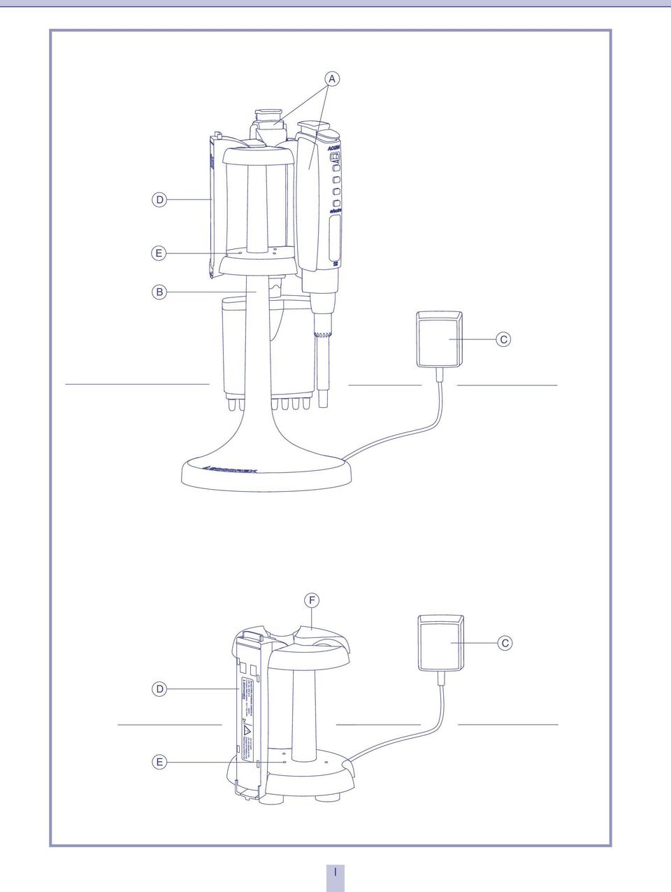
9 instrument description The Acura electro is a motorized, microprocessor controlled air displacement pipette. Energy is provided by a long life NiMH battery pack located in the pipette handle. This power handle can be replaced with a fully charged one within seconds, thus ensuring continuous work-flow without loss of set parameters. Acura electro 926 XS models allows precise and reproducible pipetting within 0.1 µl to 1000 µl. Acura electro 936 macromodels cover volumes from 0.1 to 10 ml. Multichannel Acura electro 956 with 8 and 12 channel range between 0.5 µl and 350 µl. All volumetric modules (lower assemblies) are interchangeable on the same control unit (upper assembly). The Justip ejection system provides height adjustment of the single and multichannel tip ejector. View (see p. i) A) Acura electro pipettes B) Charging stand for electronic pipette and power handle C) Power supply with cord D) Power handle E) Charging LED F) Battery charging stand Keys and functions (fig. 1) 1) 2 positions start button 2) 3 positions speed selector 3) Programming key (mode) for choosing : Pipetting modes Aspiration in tactile mode Side of display reading Installed volumetric module 4) Set key for entering selection or emergency stop 5) Selection keys (+/-) for choosing : Volumes Calibration settings Volume ranges Left/right display reading Cycle counter Mixing 6) LCD display (see fig. 3 for details) 7) Tip ejector button 8) Power handle 9) Control unit 10) Interchangeable volumetric module 11) Justip ejection system 12) Clips 13) Pipette nozzle Start button (fig. 2A) The start button has two working positions : until first stop (1) to work at the slow pipetting speed until second stop (2) to work at the selected pipetting speed LCd display (fig. 3) 1) Forward pipetting mode 2) Tactile pipetting mode 3) Reverse pipetting mode 4) Dilution mode, volume sequence (vol. 1, 2 or 3) 5) Stepper mode 6) Battery level indicator 7) Pipetting : aspirating or dispensing 8) Digits for volume display or messages 9) Current volume units (µl or ml) 10) Sign requiring user input (selection or validation) power handle (fig. 4) The rechargeable power handle contains NiMH batteries of 300 mah/4.8v. Charge a fully discharged power handle in less than 1.5 hours. Optional charging stands (fig. 5 and 6) Charging stand for 4.8V Acura electro and power handles (fig. 6) with 3 charging positions Compact battery charging stand (fig. 5) : allows to simultaneously charge up to 3 power handles power supply (fig. 7 and 8) Input : , 50/60 Hz Out put : 7.5 VDC Supplied with electrical cord and plug Various plug styles available depending on user location. See ordering information 5
 are interchangeable on the same control unit (upper assembly).")
10 use OF ThE instrument Supply contents Accessories supplied with the Acura electro may vary, depending on country. Check exact contents on packaging label. All elements also available separately. Refer to chapter Ordering information for more details. Note : Keep original packaging for adequate instrument protection during future transport or shipment. inserting power handle (fig. 4A) The power handle fits at the back of the pipette control unit. Insert and click in as shown. The initialisation starts automatically, followed by a self-calibration test. The display shows RE-CAL. Note : Charge power handle completely before first use. replacing power handle (fig. 4B) To remove the handle from control unit, press lock trigger located at the bottom of the handle and lift gently. Note : Pipetting data are kept in memory even during battery change. They will show again automatically upon re-inserting power handle. Charging power handle (fig. 5 and 6) The power handle can be charged in three different ways : 1) Attached to the electro pipette and placed on the charging stand 2) Alone, placed on charging stand 3) Alone, placed on the compact battery charging stand (to be ordered separately) The red LED goes on when charging a power handle. The green LED indicates that charging is completed and goes on stand by with minimal energy consumption. Maximal battery capacity is obtained after a few full charging/discharging cycles. At maximum capacity, power handles allow for over 3000 forward pipetting movements (full plunger stroke on a single channel micropipette) without recharging. Notes : If unused for 10 minutes, the Acura electro switches automatically to an energy saving stand-by mode (display switches off) to guarantee a longer operation. Simply press start button to re-activate instrument. 6
 To remove the handle from control unit, press lock trigger located at the bottom of the handle and lift gently.")
11 parameter SETTiNG holding the electronic pipette (fig. 1) The ergonomic shape of the Acura electro allows long pipetting series without hand fatigue. 2 Place finger rest on the phalanx of forefinger. The thumb reaches naturally start button (1) and ejector button (7), both easily activated. Multichannel casing revolves to allow the selection of the best working position Left or right display reading Configuration for left or right handed operation (> 0.5 sec.) Validate function Select Validate side (> 0.5 sec.) Back to current pipetting mode Note : After selection of left or right display reading, the last pipetting mode used will be displayed. 7

12 parameter SETTiNG Beeping sound Beep sound on keys can be turned on/off anytime. Beeping sound configuration (> 0.5 sec.) Validate function Select Validate (> 0.5 sec.) Back to current pipetting mode Note: Selecting the "off" mode will disable all warning sounds. 8
 Back to current pipetting mode Note: Selecting the \"off\" mode")
13 parameter SETTiNG Forward mode, programming and pipetting In forward mode, the exact volume desired is aspirated. Liquid dispensing is automatically followed by a short excess plunger movement (blow out). Plunger returns back to its initial position one second later. Forward pipetting Select mode Validate mode Last settings appear by default Choice of volume Ex : select 400 µl Validate volume pipetting in forward mode start button gently until first stop to work at the slow pipetting speed. fully (second stop) to work at the selected pipetting speed (fig. 2A). Aspiration dispensing Note s: Plunger stays down when start button is kept pressed, and returns to initial position when released. Slightly touch reservoir wall when dispensing. 9
 to work at the selected pipetting speed (fig. 2A).")
14 parameter SETTiNG reverse mode, programming and pipetting In reverse mode, the liquid is aspirated in excess of the selected volume. However, the set volume only will be delivered. The excess volume remains in the tip and can be kept or discarded. The reverse pipetting mode is recommended for viscous, volatile or foaming liquids. Choice of reverse pipetting mode Select Validate mode Last settings appear by default Choice of volume Ex : select 150 µl Validate volume pipetting in reverse mode start button gently until first stop to work at the slow pipetting speed. fully (second stop) to work at the selected pipetting speed (fig. 2A). Aspiration dispensing Excess volume Double click Notes : Skip purge by holding start button down after dosing is completed. The next sample is aspirated directly after release of the start button. Slightly touch reservoir wall when dispensing. 10
 to work at the selected pipetting speed (fig. 2A).")
15 parameter SETTiNG Stepper mode, programming and pipetting In stepper mode, the volume aspirated is in small excess of the sum of every single aliquot. It is distributed step by step according to volume and number of aliquots programmed by the user. Choice of stepper pipetting mode Select Validate mode Last settings appear by default Choice of volume Ex : select 50 µl Validate volume Display show maximal number of aliquots possible for the selected volume Choice : number of aliquots Ex : select 15 x Validate aliquots maximum number of aliquots Acura electro 926 XS Volume range maximum numbers µl of aliquots x 0.1 µl or 10Y 20 x 0.5 µl x 1 µl x 2.5 µl x 5 µl x 10 µl x 50 µl Acura electro 956 (8-12 channels) Volume range maxumim numbers µl of aliquots x 0.5 µl x 2.5 µl x 10 µl x 20 µl Acura electro 936 Volume range ml maximum numbers of aliquots x 0.1 ml x 0.25 ml x 0.5 ml 11

16 parameter SETTiNG pipetting in stepper mode start button gently until first stop to work at the slow pipetting speed. fully (second stop) to work at selected pipetting speed (fig. 2A). Aspiration (Ex: 15 x 50 µl) Ready dispensing Number of aliquots decrease after each dispensing dispensing Excess volume see next page Note : Slightly touch reservoir wall when dispensing. 12

17 parameter SETTiNG Stepper mode, excess volume control Current display Keep excess volume, ex. aspiration of same liquid or Blow out excess volume Double click ready for aspiration of new liquid Stepper mode, interruption of pipetting sequence Current display End of pipetting Blow out residual volume Double click ready for new filling 13

18 parameter SETTiNG dilution mode, programming and pipetting In dilution mode, up to 3 volumes of different liquids (each separated by an air bubble) will be aspirated. The total resulting volume is then dispensed in a single dose. Choice of dilution pipetting mode Select Validate mode Choice of 1st volume Ex : select 250 µl Validate volume 1 Choice of 2nd volume Ex : select 100 µl Validate volume 2 Choice of 3rd volume Ex : select 50 µl (optional) No 3rd volume? Select 0 µl Validate volume 3 Note : Air bubbles in macrotips (Acura electro 936 models) only serve the purpose of separating liquid at the lower tip area. 14
 No 3rd volume?")
19 parameter SETTiNG pipetting in dilution mode start button gently until first stop to work at the slow pipetting speed. fully (second stop) to work at the selected pipetting speed (fig. 2A). Aspiration 1st volume Aspiration air bubble Lift tip out of the liquid, Aspiration 2nd volume Aspiration air bubble Lift tip out of the liquid, Aspiration 3rd volume (if programmed) dispensing V1+V2+V3 ready for new filling Note : Slightly touch reservoir wall when dispensing. 15
 dispensing V1+V2+V3 ready for new filling Note :")
20 parameter SETTiNG dilution mode, interruption of pipetting sequence Current display End of pipetting Blow out residual volume Double click ready for new filling 16

21 parameter SETTiNG Tactile mode, programming In tactile mode, aspiration or pipetting is activated when start button is pressed. The process stops when button is released. It starts again by pressing start button. This mode is useful for liquid measurement/titration or gel loading. Choice of tactile pipetting mode Select Validate mode Last settings appear by default Choice of maximum volume Ex : select 400 µl Validate volume Tactile mode, pipetting measurement of unknown volume start button gently until first stop to aspire liquid. Release button to stop aspiration. again to continue aspiration. Aspiration of unknown volume until 1 st stop and maintain Display from 0 to 400 Release button = stop until 1 st stop = continue aspiration dispensing TACT until 2 nd stop ready for new filling 17
22 parameter SETTiNG Tactile mode, pipetting Titration or gel loading start button until second stop to aspire set volume. gently button until stop for dispensing. Release button to stop dispensing, or press again to continue distribution. Aspiration set volume until 2 nd stop dispensing End of dispensing until 1st stop and maintain Display from 400 to 0 Release button = stop until 1 st stop = continue dispensing Blow out residual volume Double click ready for new filling Note : Slightly touch reservoir wall when dispensing. Tactile mode interruption of pipetting sequence End of work Blow out residual volume Double click ready for new filling 18
23 parameter SETTiNG mixing Available in any pipetting modes (exept tactile mode), the mixing performs consecutive back and forth aspiration/dispensing of the set volume. It is only possible after pipetting or purge steps are over. mixing with 3 cycles of aspiration/dispensing or Continuous mixing 1 x Keep key pressed MIXING MIXING Back to pipetting Release key Last settings appear by default pipetting cycle counter Counter displays number of cycles performed since last zeroing. Consecutive aspiration and dispensing are counted as one cycle. display cycle counter 2 x COUNT reset counter (> 1 sec.) COUNT Back to pipetting Release key Last settings appear by default 19
24 OpErATiON Selection of pipetting speed (fig. 2B) Three pipetting speeds are available. Simply move the selector from left to right (slow/fast) to adapt working speed to the type of liquid or to a specific application. Independently 10 from the speed selection, it is always possible to aspirate or distribute at the slow speed by gently pressing start button half way (feel first stop). Pipetting speed can not be modified when working with tactile mode Charge level of power handle (fig. 3) Pay attention to battery indicator on LCD to avoid unexpected power cut-off. For appropriate handling of the power handle, refer to chapters on Replacing power handle (fig. 4B) and Charging power handle (fig. 5 and 6) for more details. LCd display SiGNiFiCATiON/CAuSE SOLuTiON Battery fully charged Battery partially charged Low battery It is recommended to charge battery after pipetting work is finished or to replace power handle Battery almost empty Energy level insufficient Instrument will switch off Replace or charge power handle immediately Note : Always keep one or more spare power handle(s) available on the charging stand. 20
25 OpErATiON Changing volumetric module Lower assembly of the Acura electro is interchangeable on a single control unit (upper assembly). Pipetting sequence must be completed before disassembling. disassembling volumetric module up 2 ml (fig. 9 and 9a inside front cover) 1 ejector button to the bottom 2 Hold screw of tip ejector and slightly turn to the left. Pull out tip ejector (see arrows on handle). 3 Unscrew barrel 4 Unclip plunger Before storing volumetric module, reassemble plunger, barrel, and ejector and place protection cap (accessory, Cat. No ) on the top. Assembling Remove protection cap and pull out plunger 5 Hold plunger between thumb and index finger and clip plunger Note : Plunger must be clicked in the control unit before assembling the module. 3 Screw on barrel 1 ejector button to the bottom 2 Introduce ejector screw into the control unit (see arrows on handle). Slightly turn right to lock. Release ejector button Enter module data in control unit prior to use, as describbed in chapter Programming volumetric module. disassembling macro volumetric module 5 ml to 10 ml (fig. 10 inside front cover) 1 Slightly turn ejector nut to unclip from ejector cap 2 Unscrew barrel, then gently pull barrel to unclip plunger rod 3 ejector button to the bottom 4 Turn ejector cap to the left and pull out Before storing volumetric module, reassemble ejector nut and cap then place protection cap (accessory, Cat. No ) on the top. Assembling Remove protection cap 5 Pull out plunger rod and introduce tip or rod in side hole to prevent from retracting 6 Introduce plunger rod in control unit and click in Note : Plunger must be clicked in the control unit before assembling the module. If difficulty to pull out plunger, use the small pin supplied in the box when ordering additional volumetric module. Hold pipette nozzle and screw barrel firmly 3 ejector button, introduce tooth of ejector cap in recess (see arrows on handle), and turn right to lock Enter module data in control unit prior to use as described in chapter Programming volumetric module. Notes : Power handle must be connected on control unit prior to re-assembling volumetric module. Watch for not activating programming keys when changing volumetric module. Important: Before the very first use of a new volumetric module, perform pipette calibration according to chapter Calibration. 21
26 OpErATiON Changing volumetric module (continued) disassembling multichannel volumetric module (fig. 12 inside front cover) 1 ejector button 2 Turn ejector nut to the left till its lowest position, unclip ejector ring and release ejector button 3 Hold volumetric module firmly with one hand and, while pulling down casing, rotate slowly to unscrew 4 Gently unclip plunger rod. Before storing volumetric module, place protection cap (accessory, Cat. No ) on the top. Assembling Remove protection cap 5 Pull out plunger rod and introduce small pin (i.e. paper clip) in side hole to prevent from retracting 6 Introduce plunger rod in control unit and click in Note : Plunger must be clicked in the control unit before assembling the module. Hold casing with fingers pulling against barrel extremities 7 Slowly screw volumetric module while positionning tooth of ejector ring in recess (see arrows on handle) 8 ejector button, turn ejector ring to the right until tooth clicks in and release ejector button Control proper functioning of ejector button. Set ejector height to desired position. Enter module data in control unit prior to use as described in chapter Programming volumetric module. Notes : Power handle must be connected on control unit prior to re-assembling volumetric module. Watch for not activating programming keys when changing volumetric module. Important: Before the very first use of a new volumetric module, perform pipette calibration according to chapter Calibration. 22
27 OpErATiON programming of volumetric module When new volumetric module is inserted in control unit, user must enter corresponding parameters prior to start working Choice of volumetric module Ex : module ranging µl Last settings appear by default Validate the choice Instrument performs a self-control test automatically Select pipetting mode according to chapter parameter setting Note : "X" stands for reduced length volumetric module. Correction of volumetric module selection It is also possible to access the menu Programming of volumetric module at anytime. Current display Access volumetric module menu (> 0.5 sec.) Validate Correction of volumetric module selection Ex : 8-channel module ranging 5-50 µl 23
28 OpErATiON Correction of volumetric module selection (continued) Correction of volumetric module (continued) Instrument performs self-control test automatically Select pipetting mode according to chapter programming Warning: The programmed volumetric module must correspond to the one fitted on the pipette assembly. use of pasteur pipette (Acura 936, 2 ml and 5 ml) Glass Pasteur pipettes are of advantage in handling PP affecting solvents. Optional adapter-nozzles fit macro models to accomodate standard 2 ml Pasteur pipettes (ext. Ø mm) in addition to Polypropylene tips. Model ml Cat. No Model ml Cat. No Slightly grease O-rings in adapter for tight Pasteur pipette fitting. Warning: Do not set volume higher than 2 ml. Adjustment of tip ejector (fig. 14 and 15) The Justip system allows instant height adjustment (+/- 2 mm) of ejector for best fitting of the tip used (optimal distance). Set the correct position (~0.5 mm space between tip and ejector) by rotating ejector screw to the left or to the right (LO - HI). Click stops prevent any unwanted change while pipetting. Note : Ejector head on multichannel models designed for soft, sequential tip removal. ~ 0.5 mm ~ 0.5 mm ~ 0.5 mm Acura 926 Acura 936 fig. 14 Acura 956 fig
29 25
30 maintenance ANd STEriLiSATiON The Acura electro requires little maintenance. To obtain long term trouble free use, special attention during pipetting and regular cleaning are recommanded. Cleaning External parts of control unit, power handle and charging stands are cleaned with damped cloth Volumetric module, once disassembled according to instructions in chapter Operation, can be cleaned, or soaked in appropriate decontamination or disinfecting solutions. Ultra-sonic bath helps to remove sticking residues Warning : No liquid must penetrate into control unit (upper assembly). On volumetric modules up to 1000 µl, plunger tightness is provided by PTFE sleeve on O-ring or with a lip seal. Grease slighthly lip seal or O-ring and sleeve. Also grease plunger, O-ring and barrel wall of macro models before reassembling Any defective part must be replaced. Order original spare parts from authorised dealers replacement of tightness parts (models 926 XS, 936 and 956) ptfe sleeve, single channel micro-volumetric modules up to 20 µl Tightness parts are not accessible on 2, 10, 10Y and 20 µl models. In case of tightness problem, the whole barrel must be changed. Do not force the plunger into the barrel. To garantee tightness, minimum friction and spare parts compatibility, the PTFE sleeve can not be changed by itself. Changing the barrel assembly, including plunger is necessary. Note : Plunger must be "clicked" with the control unit before assembling the volumetric volume. 26 Remove volumetric module from control unit according to instructions in chapter Operation (fig. 9) O-ring and ptfe sleeve, single channel micro-volumetric modules (50 µl and 100 µl) Remove volumetric module from control unit according to instructions in chapter Operation (fig. 9) Lip seal single channel micro-volumetric modules (200 µl and 1000 µl) Remove volumetric module from control unit Clean the plunger and apply thin layer of grease according to instructions in chapter Operation (fig. 9 and 9b) diameter and between the lips Slightly grease the lip seal on the external Lift both clips of the cylinder head Reposition the lip seal inside the cylinder and Remove the cylinder head clip cylinder head Gently remove the lip seal with fingers or with a tip. Reassemble according to instructions in chapter "Operation" O-ring, single channel macro-volumetric modules Remove volumetric module from control unit according to instructions in chapter Operation (fig. 9a and 10) both barrel clips with fingers to separate from bonnet for 5 ml and 10 ml modules (fig. 11) Pull out plunger assembly. Unscrew plunger rod and remove washers and spring Change parts if needed. Grease O-ring, washer and barrel Reassemble plunger assembly, barrel and bonnet according to instructions in chapter Operation
31 maintenance ANd STEriLiSATiON replacement of tightness parts (continued) Barrel change, multichannel volumetric modules Note : Tightness O-ring cannot be removed from barrel. Change barrel if tightness is deficient. Remove volumetric module from control unit according to instructions in chapter «Operation» (fig. 12) both clips of cover with pointed tool and remove casing (fig. 13) bottom clips (a) of barrel holder and separate (b) Pull out barrels (c) Apply thin, even grease layer on all surface length of plunger before reassembling Introduce barrel on plunger. Separate both plate of barrel holder, reposition barrel Clip barrel plate, all barrels must be sitting properly and aligned Place assembly in casing and clip on cover Notes : Plunger must be "clicked" with the control unit before assembling the volumetric volume. Markings on casing (volume) and on cover (Justip) should appear on opposite sides. Nozzle barrel O-rings on 200 µl module can be changed if needed (ref ) Sterilisation Only the volumetric module (lower part) is autoclavable at 121 C (20 minutes, 1 atm). Disassemble from control unit according to instructions in chapter Operation. Before autoclaving, remove nozzle filter on 936 models. Autoclave volumetric module as one assembly. Parts must be cooled down and completely dry before mounting on control unit. Check tightness and accuracy after first cycle, then regularly but at least after 50 autoclaving cycles. Correct autoclaving and resulting sterility are the responsibility of the user. Note : Setting parameters on the Acura electro must correspond to those of the assembled volumetric module. 27
32 instrument CALiBrATiON Each Acura electro pipette is factory tested for conformity according to ISO 8655 standards. Calibration parameters are permanently memorised in the instrument's micro processor. If performance results are no longer within recommended values, for instance after QC check, or replacing parts, or if changes occur in physical parameters (liquid density, temperature, atmospheric pressure), re-calibration is easily performed through the calibration menu. Factory calibration done in forward mode. Calibration can be performed in forward, reverse, step or dilution modes but not in tactile mode. Warning: A calibration is necessary before the very first use of a volumetric module other than the one supplied with the instrument (even if same range). It is recommended to control instrument performance in accordance with internal laboratory procedures (SOP / GLP, etc.) or at least once a year. Calibration increments In the calibration menu, QC-CAL is the original calibration value of a factory-calibrated instrument. Other volumetric modules purchased as accessories will display 0 as target calibration value. Calibration is performed by changing the calibration unit figure according to following values : Volumetric module (lower assembly) 2 µl 10 µl 20 µl 50 µl 100 µl 200 µl 350 µl Calibration increment ± µl ± µl ± µl ± µl ± µl ± 0.05 µl ± 0.1 µl Volumetric module (lower assembly) 1000 µl 2 ml 5 ml 10 ml Calibration increment ± 0.25 µl ± 0.5 µl ± 1.25 µl ± 2.5 µl Calibration procedure User can perform a 2-point (Vmin and Vmax) or 3-point (Vmin, Vmid and Vmax) calibration. See graphs below: Calibration increments 2-point calibration Calibration increments 3-point calibration better precision Vmin Vmax Vmin Vmid Vmax 28
33 7 instrument CALiBrATiON New calibration When performance results are no longer within recommended values, a calibration should be performed using an analytical balance after insuring perfect working condition of the instrument. Proceed as follow for each calibration point. Finish pipetting sequence Be sure desired mode is set before proceeding Access calibration menu first (> 0.5 sec.) Then press simultaneously Validate Select calibration point Validate 7 Display shows QC-CAL for a factory-calibrated instrument where the original parameters have not been modified. If modified, display shows the number of calibration increments previously selected Change calibration Ex : volume parameter reduction of 0.75 µl (= 3 x 0.25 µl / increment) on a 1000 µl model Validate Note : When purchasing a new volumetric module as an accessory, it is important to introduce calibration parameters before very first use. To do so, perform calibration according to chapter Calibration procedure. The values entered are automatically memorised for each volumetric modules and modes. 29
34 TrOuBLE ShOOTiNG Error messages LCd display CAuSE SOLuTiON Plunger sticking or dragging Plunger rod not clipped before assembling Microprocessor detected deviation between set volume and effective plunger travel Plunger rod not clipped before assembling Disassemble volumetric module according to chapter Operation Clean plunger according to chapter Maintenance Reset instrument (see below) Reconnect plunger rod according step 5 and 6 of page 21 and 22. Reset instrument (see below) Contact authorised dealer for control if error persists Reset instrument (see below) Contact authorised dealer if error become frequent Reconnect plunger rod according step 5 and 6 of page 21 and 22. Reset instrument (see below) Volumetric module disassembled when pipetting sequence is not completed Reset instrument (see below) Confirm selection of volumetric module after re-assembling Only in dilution mode Volumes programmed larger than maximal aspiration capacity Reset instrument (see below) instrument reset Error message reset Double click on start button Error message Only in dilution mode Select new volume 30
35 TrOuBLE ShOOTiNG instrument reset (continued) Or change calibration settings then Refer to chapter Calibration for new setting Other failures Observation Possible cause Action power handle does not fit pipette control unit power handle or instrument is not charging/no red light red light on charger stand not lid plug do not fit into stand No display LCd display on but no reaction when pressing start button poor instrument performance Control if compatible 4.8V power handle Control if compatible 4.8V device Micropipette or power handle not sitting correctly on stand Control for correct power supply model 4.8V Instrument in stand-by Battery is discharged Volumetric module not correctly locked Lack of tightness Instrument not calibrated Instrument pipetting viscous, or volatile solutions, liquid temperature not comprised between C Exchange with 4.8V power handle Exchange with 4.8V compatible device Reposition instrument or power handle Use 4.8V power supply start button to activate instrument Charge power handle or replace if damaged Check volumetric module Check proper tip fitting. Use tips compatible with the instrument Check tip cone, change if damaged Check O-ring PTFE sleeve, and lipseal change if damaged Perform new calibration New calibration with specific solution or temperature reduced battery life span Power handle damaged Replace power handle Too much friction in lower assembly Clean lower assembly Wrong distributed volume Long pipetting time plunger moves erratically Erroneous programming of volumetric module Plunger sticking or dragging Motor drive blocked Set parameters correctly Disassemble volumetric module, clean, apply, apply thin layer of grease on plunger Contact authorized dealer for control 31
36 performance Performance values obtained in Forward pipetting mode with bi-dist. water at constant temperature (± 0.5 C) between 20 and 25 C according to ISO Acura electro 926 XS (reduced length) Volume division inaccuracy (E%) imprecision (CV%) Tip style µl µl min. vol. mid vol. max. vol. min. vol. mid vol. max. vol <+/- 2.5 % 1 <+/- 1.2 % <+/- 0.9 % < 2.5 % 1 < 1.5 % < 0.8 % Ultra 10 µl <+/- 1.2 % 2 <+/- 0.8 % <+/- 0.6 % < 1.5 % 2 < 0.7 % < 0.35 % Ultra 10 µl Y 0.05 <+/- 1.2 % 2 <+/- 0.8 % <+/- 0.6 % < 1.7 % 2 < 0.8 % < 0.4 % 200 µl <+/- 1.2 % 2 <+/- 0.6 % <+/- 0.5 % < 1.2 % 2 < 0.4 % < 0.3 % 200 µl <+/- 1.0 % 2 <+/- 0.6 % <+/- 0.5 % < 0.7 % 2 < 0.3 % < 0.25 % 200 µl <+/- 1.0 % 2 <+/- 0.6 % <+/- 0.5 % < 0.7 % 2 < 0.3 % < 0.2 % 200 µl <+/- 1.0 % 2 <+/- 0.6 % <+/- 0.4 % < 0.6 % 2 < 0.2 % < 0.15 % 200 µl <+/- 0.8 % 2 <+/- 0.5 % <+/- 0.4 % < 0.4 % 2 < 0.15 % < 0.1 % 1000 µl Acura electro 936 Volume division inaccuracy (E%) imprecision (CV%) Tip style ml ml min. vol. mid vol. max. vol. min. vol. mid vol. max. vol <+/- 1.5 % 2 <+/- 1.0 % <+/- 0.5 % < 0.6 % 2 < 0.3 % < 0.15 % 2 ml <+/- 1.2 % 2 <+/- 0.8 % <+/- 0.5 % < 0.6 % 2 < 0.3 % < 0.15 % 5 ml <+/- 1.0 % 2 <+/- 0.7 % <+/- 0.5 % < 0.5 % 2 < 0.2 % < 0.15 % 10 ml Measurements done with nozzle protection filters. Acura electro channels Volume division inaccuracy (E%) imprecision (CV%) Tip style µl µl min. vol. mid vol. max. vol. min. vol. mid vol. max. vol <+/- 3.5 % 2 <+/- 1.5 % <+/- 1.0 % < 3.0 % 2 < 0.9 % < 0.7 % Ultra 10 µl <+/- 1.0 % 2 <+/- 0.9 % <+/- 0.8 % < 1.0 % 2 < 0.6 % < 0.4 % 200 µl <+/- 0.9 % 2 <+/- 0.7 % <+/- 0.6 % < 0.6 % 2 < 0.4 % < 0.25 % 200 µl <+/- 1.0 % 2 <+/- 0.8 % <+/- 0.6 % < 0.6 % 2 < 0.4 % < 0.25 % 350 µl Acura electro channels Volume division inaccuracy (E%) imprecision (CV%) Tip style µl µl min. vol. mid vol. max. vol. min. vol. mid vol. max. vol <+/- 3.5 % 2 <+/- 1.5 % <+/- 1.0 % < 3.0 % 2 < 0.9 % < 0.7 % Ultra 10 µl <+/- 1.0 % 2 <+/- 0.9 % <+/- 0.8 % < 1.0 % 2 < 0.6 % < 0.4 % 200 µl <+/- 0.9 % 2 <+/- 0.7 % <+/- 0.6 % < 0.6 % 2 < 0.4 % < 0.25 % 200 µl <+/- 1.0 % 2 <+/- 0.8 % <+/- 0.6 % < 0.6 % 2 < 0.4 % < 0.25 % 350 µl Performance measured at µl, 2 10% of nominal value. Notes: Use of other tips than those recommended, as well as pipetting viscous or volatile liquids may lead to performance deviation compared to those shown in the above figure. Product specifications subject to change without prior notice. Performance value obtained in Forward mode. Small deviations may exist when using other pipetting modes. To obtain best possible performance with one specific pipetting mode, it is recommended to perform a new calibration. 32
37 performance Performance values obtained in Forward pipetting mode with bi-dist. water at constant temperature (± 0.5 C) between 20 and 25 C according to ISO Acura electro 926 (regular length) Volume division inaccuracy (E%) imprecision (CV%) Tip style Volumetric µl µl min. vol. mid vol. max. vol. min. vol. mid vol. max. vol. module <+/- 3.0 % 1 <+/- 1.8 % <+/- 1.5 % < 3.0 % 1 < 1.6 % < 0.9 % Ultra 10 µl <+/- 2.2 % 2 <+/- 1.1 % <+/- 0.9 % < 1.7 % 2 < 0.8 % < 0.4 % Ultra 10 µl Y 0.05 <+/- 2.2 % 2 <+/- 1.1 % <+/- 0.9 % < 2.0 % 2 < 1.0 % < 0.6 % 200 µl Y <+/- 2.0 % 2 <+/- 1.0 % <+/- 0.8 % < 1.5 % 2 < 0.5 % < 0.4 % 200 µl <+/- 1.5 % 2 <+/- 0.8 % <+/- 0.6 % < 1.0 % 2 < 0.4 % < 0.3 % 200 µl <+/- 1.5 % 2 <+/- 0.8 % <+/- 0.6 % < 1.0 % 2 < 0.35 % < 0.25 % 200 µl <+/- 1.5 % 2 <+/- 0.8 % <+/- 0.5 % < 0.7 % 2 < 0.3 % < 0.2 % 200 µl <+/- 1.5 % 2 <+/- 0.7 % <+/- 0.5 % < 0.5 % 2 < 0.25 % < 0.15 % 1000 µl Performance measured at 1 0.5µL, 2 10% of nominal volume. Notes: Use of other tips than those recommended, as well as pipetting viscous or volatile liquids may lead to performance deviation compared to those shown in the above figure. Product specifications subject to change without prior notice. Performance value obtained in Forward mode. Small deviations may exist when using other pipetting modes. To obtain best possible performance with one specific pipetting mode, it is recommended to perform a new calibration. 33
38 WArrANTy Your Acura electro and power handle are guaranteed against any material or manufacturing defects for the period of time specified in its QC certificate. Damages due to non-respect of manufacturer s instructions, safety precautions or autoclaving conditions, as well as material colour alteration are excluded from the warranty. Repair and replacement of parts do not extend warranty time. Claims for warranty are void if instrument has been tempered. Should regular maintenance not eliminate a detected defect, return the instrument to the dealer from whom it was purchased after obtaining return authorisation. Note : Decontaminate volumetric module of the instrument prior to returning it. 34
39 35
40 OrdEriNG information micropipettes Initial package includes electronic pipette, individual QC certificat, two power handles, charging stand, power supply, accessories and operating instructions. Pipette alone is supplied with individual QC certificate, power handle, Qualitips pipette tips samples and operating instructions. Acura electro 926 XS (reduced length) Volume division Tip style initial package* pipette alone µl µl Cat. No. Cat. No Ultra 10 µl E Ultra 10 µl E Y µl YE Y µl E µl E µ L E µl E µl E Acura electro 936 Volume division Tip style initial package* pipette alone ml ml Cat. No. Cat. No ml E ml E ml E Acura electro channels Volume division Tip style initial package* pipette alone µl µl Cat. No. Cat. No Ultra 10 µl E µl E µl E µl E Acura electro channels Volume division Tip style initial package* pipette alone µl µl Cat. No. Cat. No Ultra 10 µl E µl E µl E µl E * Replace E by country code if other plug type than Europe style needed: G = UK, U = USA-Japan, A = Australia-NZ 36
41 OrdEriNG information Volumetric module all models Volumetric Volume Tip style Cat. No. module Reduced length µl Ultra 10 µl XS µl Ultra 10 µl XS µl 200 µl YXS 1 20 µl 200 µl XS µl 200 µl XS µl 200 µl XS µl 200 µl XS µl 1000 µl XS Regular µl Ultra 10 µl length µl Ultra 10 µl µl 200 µl Y 1 20 µl 200 µl µl 200 µl µl 200 µl µl 200 µl µl 1000 µl Volumetric Volume Tip style Cat. No. module Macro ml 2 ml ml 5 ml ml 10 ml channel µl Ultra 10 µl µl 200 µl µl 200 µl µl 350 µl channel µl Ultra 10 µl µl 200 µl µl 200 µl µl 350 µl Accessories and charging stands description packaging Cat. No. Power handle, blue color, NiMH 4.8V 1 / pk Power handle, blue color, NiMH 4.8V 2 / pk Charging stand 3 positions for pipettes or power handles 1 / pk Charging rack for power handles only (3 positions) 1 / pk Power supply V - Europe style plug 1 / pk E Power supply V - UK style plug 1 / pk G Power supply V USA/Japan style plug 1 / pk U Power supply V Australia/NZ style plug 1 / pk A Nozzle protection filters for 2mL and 5mL models 250 / pk Nozzle protection filters for 10mL model 100 / pk Pasteur pipette adapter nozzle for 2mL model 1 / pk Pasteur pipette adapter nozzle for 5mL model 1 / pk
42 OrdEriNG information Qualitips pipette tips Acura electro Qualitips compatibility chart 926 XS and 800 module µl µl µl (Y) 1-20 µl µl µl µl µl ml ml ml µl µl µl µl microtips, 10 µl Natural ultra-microtip B + R Natural ultra-microtip with filter FR Natural microtip B + R Natural microtip with filter FR + AFB Natural gel loading tip GR microtips, 20 µl Natural tip with filter FS + FR Natural gel loading tip with filter GFR microtips, 100 µl Natural tip with filter FR Natural gel loading tip with filter GFR microtips, 200 µl Natural universal tip B + R Yellow universal tip B + R Natural superior tip B + R Natural tip B + R Yellow tip B + R Yellow tip B + R Natural gel loading tip GR Natural extended tip with filter LFS + LFR microtips, 300/350 µl Natural tip B + R Natural tip with filter FR + AFB microtips, 1000 µl Natural universal tip B + R Natural tip B +R Blue tip B +R Blue tip B +R Natural tip with filter FR + AFB + FS macrotips Macrotip (2 ml) Macrotip B + R (5 ml) Macrotip (10 ml) x x x x x x x x x x x x x 1) x 1) x 1) x x x 1) x 1) x x x x x x 1) x x x x x x x x x x x x x x x x x x x x x x x x x x x x 1) x x x x x x x x 1) x x x x x x 38 x x x x x x x x x B = bag, F = filter, G = gel loading, L = long, R = rack, S = single wrapped, AF = autoclavable filter, ER = empty rack 1) Only to max. volume of the tip x x x x x x x x
43 NOTES 39
44 Ac u r A electro 926 XS 2, 10, 10Y, 20 µl 50, 100 µl 200 µl 1000 µl IV
45 regular lenght volumetric module 2, 10, 10Y, 20 µl all other sizes V
46 Ac u r A electro ml 5, 10 ml VI
47 Ac u r A electro µl all other sizes VII
48 DECL DECLARATION OF CONFORMITY DECLARATION OF CONFORMITY DECLARATION OF CONFORMITY SOCOREX ISBA S.A. We declare un CHAMP-COLOMB SOCOREX ISBA 7 S.A ECUBLENS/LAUSANNE CHAMP-COLOMB SOCOREX ISBA ECUBLENS/LAUSANNE SWITZERLAND S.A. Elec CHAMP-COLOMB SWITZERLAND ECUBLENS/LAUSANNE We declare SWITZERLAND under our sole responsability that our devices are in confo We declare under our sole responsability that our devices We declare under our sole Electronic responsability pipettes that ACURA our devices electro Electronic pipettes ACURA electro Electronic are in pipettes conformity ACURA with the electro following Council directives are in conformity with the following Council directives are in conformity with the following 98/79/EEC Council directives In vitro Diagnostic 89/336/EEC, and a 98/79/EEC In vitro 98/79/EEC Diagnostic 89/336/EEC, In vitro and amending Diagnosticdirectives 91/263, 92/31, 93/68/EEC Electromagnetic Compatibility 73/23/EE 89/336/EEC, and amending directives 91/263, 92/31, 93/68/EEC 89/336/EEC, and amending Electromagnetic directives Compatibility 91/263, 92/31, 93/68/EEC Electromagnetic 73/23/EEC, and Compatibility amending directive 93/68/EEC Low Voltage 73/23/EEC, and amending directive 93/68/EEC 73/23/EEC, and amending Low Voltage directive 93/68/EEC Low Voltage Ecublens Ecublens May 15 th, 2007 Ecublens Sylvain Christen May Sylvain 15 Director, th, 2007 Christen CEO Director, CEO Sylvain Christen Director, CEO Jean-Pierre Uldry Director, Jean-Pierre Engineering Uldry Director, Engineering Jean-Pierre Uldry Director, Engineering Operating instructions May 15 th, 2007in other languages are available in digital format CHAMP-CO Ecublens May 15 th, 2007 U. S. U F. C S. C F part u C. C15 S. part F 15 C C part 15 U. S. F C C part 15 (power supply) (power supply) (power supply) (power supply) (power supply) (power supply) Operating instructions F C also C part 15 avail able in other languages Operating instructions also Operating ENERGY STAR instructions also avail able in other qualified power languages avail able in other languages supply for a better environment ENERGY SOCOREX STAR ISBA S.A. CH. CHAMP-COLOMB 7 ENERGY qualified P. STAR power O. BOX 1024 ECUBLENS SWITZERLAND qualified supply for TEL. power a better 41-(0) FAX 41-(0) supply environment for a better : socorex@socorex.com environment SOCOREX ISBA S.A. CH. CHAMP-COLOMB 7 SOCOREX P. O. BOX ISBA 1024 S.A. ECUBLENS CH. CHAMP-COLOMB SWITZERLAND 7 P. TEL. O. BOX 41-(0) ECUBLENS 6000 FAX 41-(0) SWITZERLAND TEL. 41-(0) : socorex@socorex.com FAX 41-(0) socorex@socorex.com SOCOREX ISBA S.A. CH. CHAMP-COLOMB ECUBLENS/LAUSANNE SWITZERLAND socorex@socorex.com TEL FAX U. S. (power supp I.ELECTRO.E I.ELECTRO.E - C307 - C307 I.ELX.E - C611
Fixed and Adjustable Spacing Electronic Pipettes
 viaflo Fixed and Adjustable Spacing Electronic Pipettes viaflo Electronic Pipettes All viaflo pipettes function as repeaters, mixers, serial dilutors, manual pipettes, handheld sample processors and more!
CappController Pipette Controller. Operation Manual Version: 1.2. www.capp.dk
 CappController Pipette Controller Operation Manual Version: 1.2 www.capp.dk skal vises her. Table of Content 1. Safety Precautions... 1 2. General Description... 2 3. Getting Started... 4 3.1. Recharging
POSEIDON 2-29, 2-25 & 2-22 POSEIDON 2-29, 2-25 & 2-22 XT
 POSEION 2-29, 2-25 & 2-22 POSEION 2-29, 2-25 & 2-22 XT Repair Manual Index A. Safety precautions 3 B. Technical data 4 C. Structure 5-6. Service / Repair 7-23 E. Tools 24 F. Function 25-26 G. Electric
OPL BASIC. Dosing System for Professional Laundry machines. Contents
 OPL BASIC Dosing System for Professional Laundry machines Contents 1 Getting Started. Page 2 2 Installation. Page 4 3 Set Up & Operation. Page 8 4 Maintenance & Accessories. Page 10 5 Troubleshooting Page
Single Channel Electronic Pipettes MPA. Series
 Single Channel Electronic Pipettes MPA Series MPA-10 MPA-200 MPA-20 MPA-1200 Accurate pipetting at all times ISO 9000 CERTIFIED...Clearly a Better Value http://www.aandd.jp If you still think manual pipettes
National- Spencer Inc.
 9-27-2010 National- Spencer Inc. 19.2V HEAVY DUTY GREASE GUN PRODUCT SPECIFICATION Charger Input Power 110 VAC Battery Output Power 19.2V Battery Capacity 1500 MAH Battery Pack Charge Time 1 Hour Maximum
Omega Pipettor. Operating Instructions
 Omega Pipettor Operating Instructions www.argos-tech.com Argos Technologies, Inc. 1551 South Scottsdale Court, Suite 200, Elgin, IL 60123, Tel (US) 800-886-8675, Tel (outside US) 847-622-0456, Fax 847-622-0454
FCC COMPLIANCE STATEMENT FOR AMERICAN USERS
 FCC COMPLIANCE STATEMENT FOR AMERICAN USERS This equipment has been tested and found to comply with the limits for a CLASS A digital device, pursuant to Part 15 of the FCC Rules. These limits are designed
USER MANUAL WARNING! CONTENTS MODEL 1 SPECIFICATIONS READ ALL INSTRUCTIONS BEFORE PROCEEDING. Non-Programmable Single Stage Heat/Cool Thermostat
 Builder MODEL 1010 Series Non-Programmable Single Stage Heat/Cool Thermostat USER MANUAL Compatible with low voltage single stage gas, oil or electric heating or cooling systems, including single stage
Installation and Operating Manual p. 23. Radio push button 2 channel: HM-PB-2-WM55-2
 Installation and Operating Manual p. 23 Radio push button 2 channel: HM-PB-2-WM55-2 1. English edition 10/2013 Documentation 2013 eq-3 Ltd., Hong Kong All rights reserved. No parts of this manual may be
ROTOR LOADER OWNER S MANUAL
 ROTOR LOADER OWNER S MANUAL ROTOR LOADER OWNER S MANUAL WARNING IMPORTANT SAFETY INSTRUCTIONS AND GUIDELINES. Misuse of paintball equipment may cause serious injury or death. QUICK SET-UP GUIDE BATTERY
Portable Air Conditioner
 Portable Air Conditioner Owner's Manual Model:3 in 1 12,000 Btu/h Series 3 Please read this owner s manual carefully before operation and retain it for future reference. CONTENTS 1. SUMMARY...1 2. PORTABLE
OEM Manual MODEL 2350 ELECTRONIC DUAL CYLINDER SCALE
 OEM Manual MODEL 2350 ELECTRONIC DUAL CYLINDER SCALE Scaletron Industries, Ltd. Bedminster Industrial Park 53 Apple Tree Lane P.O. Box 365 Plumsteadville, PA 18949 USA Toll Free: 1-800-257-5911 (USA &
CL90i. 77-021 Please read these instructions before operating the product. 3 - Beam Self-Leveling Cross Line Laser
 3 - Beam Self-Leveling Cross Line Laser CL90i 77-01 Please read these instructions before operating the product Self-Leveling GB D F I E PT NL DK SE FIN NO PL GR CZ RU HU SK SI BG RO EE LV LT Contents
Luna/200. Luna/275. Ceiling hoist. User instruction. Important - warning. This manual must be read before the Luna is used
 Luna/200 Luna/275 Ceiling hoist User instruction! Important - warning This manual must be read before the Luna is used This manual is intended for technicians, installers, therapists and other personnel,
IH 17025 E Sigma Island 90
 INSTRUCTIONS FOR USE Kitchen extractor hood Type: IH 17025 E Sigma Island 90 Dear Customer!! You are now a user of the newest generation kitchen extractor hood type IH 17025 E Sigma Island 90. This hood
Owners & Installation Manual for the Sheridan, Mountainair, Pine Valley and Old Forge Ceiling Fan Family
 Owners & Installation Manual for the Sheridan, Mountainair, Pine Valley and Old Forge Ceiling Fan Family Part of the Kiva Lighting Family Custom Lighting and Fans Since 1992 1312 12th St NW Albuquerque,
Operating instructions Cordless K 10253 impact wrench
 Operating instructions Cordless K 10253 impact wrench Operational precautions General safety instructions warning! 1. Consider work area environment. Do not expose tools to rain. Do not use tools in damp
SECTION G2: CABLE PROCESSOR MODULE MAINTENANCE
 SECTION G2: CABLE PROCESSOR MODULE MAINTENANCE Cable Processor Module overview WARNING! When tipping the Cable Processor Module back, (after removing the toggle arm pin), use extreme caution not to drop
Inc. Wuhan. Quantity Pre-coated, ready to use 96-well strip plate 1 Plate sealer for 96 wells 4 Standard (liquid) 2
 2") Uscn Life Science Inc. Wuhan Website: www.uscnk.com Phone: +86 27 84259552 Fax: +86 27 84259551 E-mail: uscnk@uscnk.com ELISA Kit for Human Prostaglandin E1(PG-E1) Instruction manual Cat. No.: E0904Hu
Uscn Life Science Inc. Wuhan Website: www.uscnk.com Phone: +86 27 84259552 Fax: +86 27 84259551 E-mail: uscnk@uscnk.com ELISA Kit for Human Prostaglandin E1(PG-E1) Instruction manual Cat. No.: E0904Hu
Table of Contents. Overview 1. Pump Disassembly 2. Control Disassembly / Reassembly 7. Pump Reassembly 13. Adjustment Procedures DR Control 19
 Table of Contents Overview 1 Pump Disassembly 2 Control Disassembly / Reassembly 7 Pump Reassembly 13 Adjustment Procedures DR Control 19 Adjustment Procedures DRG Control 20 Adjustment Procedures DFR
Quick Start Guide See Inside for Use and Safety Information
 3 rd Generation Personal 3D Printer Quick Start Guide See Inside for Use and Safety Information The USB Mass Storage Device Contains the User Guide and Quick Start Guide in other Languages Congratulations
OPERATOR S MANUAL 18 VOLT, 1 HOUR CHARGER
 OPERATOR S MANUAL 18 VOLT, 1 HOUR CHARGER P110 Your battery charger has been engineered and manufactured to Ryobi s high standard for dependability, ease of operation, and operator safety. When properly
ArtisanLink Staining System is an automated special stains slide
 Technical Tips Tips on using the ArtisanLink Special Staining System Jamie Nowacek, BS, HT(ASCP) CM, QIHC, PMP Dako North America, Inc. Carpinteria, CA, USA ArtisanLink Staining System is an automated
MAP COFFEE MIA CAPSULE COFFEE MACHINE INSTRUCTION MANUAL MODEL: CM4725. Read this manual thoroughly before using and save it for future reference
 MAP COFFEE MIA CAPSULE COFFEE MACHINE INSTRUCTION MANUAL MODEL: CM4725 Read this manual thoroughly before using and save it for future reference Purchase MAP capsules at Harvey Norman stores nationwide
User Manual Color video door phone
 User Manual Color video door phone CDV-70KM Thank you for purchasing COMMAX products. Please carefully read this User s Guide (in particular, precautions for safety) before using a product and follow instructions
EVBIKE LCD Display Control User Guide. EVBIKE LCD Display Control User Guide WWW.EVBIKE.CZ - 1 -
 EVBIKE LCD Display Control User Guide WWW.EVBIKE.CZ - 1 - Table of Contents: 1) Description of the individual components and installation 2) Description of the measured quantities and user control display
RL HW / RL HW+ / RL HGW / RL HV / RL HVPW/RL HVPW-G
 Auto-Levelling Rotary Laser Level RL HW / RL HW+ / RL HGW / RL HV / RL HVPW/RL HVPW-G 77-496 / 77-429 / 77-439 / 77-497 / 77-427/ 77-441 Please read these instructions before operating the product Auto-Levelling
EPM3. Phase Sequence and Motor Rotation Tester. Users Manual
 EPM3 Phase Sequence and Motor Rotation Tester Users Manual 1 L1 L2 L3 2 3 A B C CAT 600V 3-PHASE TESTER 5 TEST M1 M2 BATT M3 EPM3 MOTOR ROTATION TESTER EPM3 MOTOR ROTATION DETERMINED WHILE FACING MOTOR
DIAMOND Retractable Rodding Robot Model SPRAYROD-R
 2004-12-21 2 1 (23) DIAMOND Retractable Rodding Robot Model SPRAYROD-R 2004-12-21 2 2 (23) Table of contents 1 TECHNICAL DESCRIPTION...4 1.1 MAIN DETAILS...5 1.2 COMPONENTS DESCRIPTION...5 1.2.1 Pneumatic
MAINTENANCE & TROUBLESHOOTING
 MAINTENANCE & TROUBLESHOOTING This section describes how to: clean the lens clean the fan intake filter replace the projection lamp replace the batteries in the remote control use the Kensington lock feature
HEAT PUMP PROGRAMMABLE THERMOSTAT
 HEAT PUMP PROGRAMMABLE THERMOSTAT SA PM 3 COOL TEMP Form 44014-01 r010408 Model 43168 Owners Manual 1 Congratulations! Heat Pump Programmable Thermostat Model 43168 THERMOSTAT CONTROLS Switches & Buttons...15
GREISINGER electronic GmbH
 T38.0.0X.6C-03 CO2 - Transmitter Operating Manual GT10 - CO2-1R GREISINGER electronic GmbH D - 93128 Regenstauf, Hans-Sachs-Straße 26 Tel.: +49 9402 / 9383-0, Fax: +49 9402 / 9383-33, email: info@greisinger.de
Introduction 1 The system 1 The meter 2 The display 3 The mode 3 The measurement 4 Coding the meter 4 How to obtain a drop of blood 6 Application of
 Introduction 1 The system 1 The meter 2 The display 3 The mode 3 The measurement 4 Coding the meter 4 How to obtain a drop of blood 6 Application of the blood 7 Procedure to test glucose 7 Procedure to
BLOOD COLLECTION MIXER
 USER S MANUAL BLOOD COLLECTION MIXER Model CM735 No. CAT.CM73522Ce Centron Technologies Corporation 319-25 Sadang-4-dong, Dongjak-ku Seoul, Korea 156-823 Tel. +82-2.522.7807 Fax +82-2.522.7806 Table of
Enterprise Telephone. Model 98390 OPERATING INSTRUCTIONS
 Enterprise Telephone Model 98390 OPERATING INSTRUCTIONS This Interquartz telephone has been manufactured to very high standards and is very easy to use. Please read this manual carefully to find out how
Carpet Washer. vax.co.uk VRS5W. Vax Careline: (UK) 0844 412 8455 (ROI) 1-800 928 308. Vax model number: Version 1.0
 0844 412 8455 (ROI) 1-800 928 308. Vax model number: Version 1.0") VRS5W Powermax User Guide V1.0.qxd:V1.0 23/7/10 15:35 Page 1 Vax Careline: (UK) 0844 412 8455 (ROI) 1-800 928 308 Carpet Washer Vax model number: VRS5W instruction manual Version 1.0 Please read carefully
VRS5W Powermax User Guide V1.0.qxd:V1.0 23/7/10 15:35 Page 1 Vax Careline: (UK) 0844 412 8455 (ROI) 1-800 928 308 Carpet Washer Vax model number: VRS5W instruction manual Version 1.0 Please read carefully
GeekDesk Max Instructions for Assembly & Use
 GeekDesk Max Instructions for Assembly & Use Work Sitting OR Standing! With the touch of a button... Elevate Your Work Instructions release 1.5, 2012-08-09 WELCOME! Thank you for purchasing a GeekDesk!
Ground Resistance Clamp On Tester
 USER MANUAL Ground Resistance Clamp On Tester MODEL 382357 Introduction Congratulations on your purchase of Extech s 382357 Ground Resistance Tester. This Clamp on device allows the user to measure ground
IMPORTANT SAFETY RULES TO FOLLOW
 WARNING FLOOR & CARPET CLEANER Any piece of equipment can be dangerous if not operated properly. YOU are responsible for the safe operation of this equipment. The operator must carefully read and follow
P22 Cal..22L.R. Operating Instructions. Semi-Automatic pistol USA. anl_us~1.qxd 13.08.2002 07:52 Seite 1. extractor
 anl_us~1.qxd 13.08.2002 07:52 Seite 1 manual safety extractor stabilizer frontsight slide Loaded chamber indicator rear sight hammer barrel trigger lock muzzle trigger mounting rail manual safety slide
SIMPLEX UNICAN LOCKS CHANGING THE CODE / COMBINATION 900 Series 1000 Series L1000 Series LP1000 Series EE1000 Series 2000 Series 2015 Series
 SIMPLEX UNICAN LOCKS CHANGING THE CODE / COMBINATION 900 Series 1000 Series L1000 Series LP1000 Series EE1000 Series 2000 Series 2015 Series 2400/2500 Series 3000 Series 3100 Series Simplex 5000 Series
Rousseau 10. User Guide
 Rousseau 10 User Guide Base station overview ➀ LED signals White, permanent light: - Base station ready, you can register a handset Slow flashing white light: - Paging call in progress - Active call (you
Foodservice Equipment Specialists P.O. Box 880 Saco, ME. / U.S.A. 04072 877-854-8006 * FAX (207) 283-8080
 283-8080") Foodservice Equipment Specialists P.O. Box 880 Saco, ME. / U.S.A. 04072 877-854-8006 * FAX (207) 283-8080 FOR SERVICE ASSISTANCE U.S. AND CANADA CALL: 1-877-854-8006 24 HOURS/DAY 7 DAYS/WEEK TABLE OF CONTENTS
Foodservice Equipment Specialists P.O. Box 880 Saco, ME. / U.S.A. 04072 877-854-8006 * FAX (207) 283-8080 FOR SERVICE ASSISTANCE U.S. AND CANADA CALL: 1-877-854-8006 24 HOURS/DAY 7 DAYS/WEEK TABLE OF CONTENTS
Use of Micropipettes
 Use of Micropipettes Prior to lab you should understand: The function of micropipettes in the laboratory Basic parts of micropipette What volumes are measured with P, P and P1 micopipettors How to read
Pipet-Lite. Multichannel Magnetic Assist Pipette. 8-, 12-, 16- (2x8), 24-channel models
, 24-channel models") Pipet-Lite Multichannel Magnetic Assist Pipette 8-, 12-, 16- (2x8), 24-channel models Introduction Pipet-Lite multichannel pipettes are based on the Pipet-Lite single-channel pipette which uses the patented
Pipet-Lite Multichannel Magnetic Assist Pipette 8-, 12-, 16- (2x8), 24-channel models Introduction Pipet-Lite multichannel pipettes are based on the Pipet-Lite single-channel pipette which uses the patented
Bench Autoclave. Standard Operating Procedure. For Installation, Use and Maintenance
 Bench Autoclave Standard Operating Procedure For Installation, Use and Maintenance 1. Introduction This SOP is intended for use with the following model, in a laboratory context: Type: Nuve Bench Top Steam
Duct Humidity Transmitter
 SDC-H Duct Humidity Transmitter Features Replaceable sensor element Humidity measurement for air ducts Minimum and maximum value memory 0 0V, 0 0mA or 0V, 4 0mA measuring signals selectable with jumpers
ATS Overhead Table Shelf System INSTRUCTION MANUAL
 ATS Overhead Table Shelf System INSTRUCTION MANUAL ATS Overhead Table Shelf System Instruction Manual Warranty Newport Corporation warrants this product to be free of defects in material and workmanship
Waters Corporation. Waters 2690/5 USER & TROUBLESHOOTING GUIDE
 Waters Corporation Waters 2690/5 USER & TROUBLESHOOTING GUIDE Contents 2690/5 Theory Setup procedures. Troubleshooting the 2690/5 User maintenance of the 2690/5 Spare Parts 2 2690/5 Theory 2690/5 Solvent
RI-215A Operator s Manual. Part Number: 71-0045RK Revision 0 Released: 10/3/05
 RI-215A Operator s Manual Part Number: 71-0045RK Revision 0 Released: 10/3/05 Warranty RKI Instruments, Inc., warrants gas alarm equipment sold by us to be free from defects in materials and workmanship,
EUROTUBO DELTALAB 4. PETRI DISHES AND LOOPS
 77 78 90 x 14 mm Petri Dish Made in polystyrene. Vented. Supplied in groups of 20 units, packaged in heat sealed bags. Code 200200 is ASEPTIC. Code 200209 is sterile by gamma radiation. Suitable for automatic
Operating Instructions Bedienungsanleitung Mode d emploi
 Operating Instructions Bedienungsanleitung Mode d emploi DW 400 www.bron-kobold.com Operating instructions DW 400 Before use Please read all the information contained in these operating instructions carefully.
- 2 - IMPORTANT SAFETY REMINDERS
 USER MANUAL IMPORTANT SAFETY REMINDERS This appliance should only be used for domestic cleaning, as described in this user guide. Please ensure that this guide is fully understood before operating the
Morini CM 162EI. Technical Data
 Morini CM 162EI Technical Data Caliber: Weight: Total Length: Total Height: Total Width: Length of Sight Line: Barrel Length: Type of Barrel: Number of Riflings: Functioning: Trigger: Path: Arrest Point:
Oceanscience Cable Chimp II Cableway ROV System User Guide and Warranty
 Oceanscience Cable Chimp II Cableway ROV System User Guide and Warranty Page 1 Table of Contents Introduction Page 3 Overview Page 3 Setup and Operation Page 5 Remote Control Page 6 Power Management Page
Operation Manual For NDJ-8S Digital Rotary Viscometer
 Operation Manual For NDJ-8S Digital Rotary Viscometer 1 Contents 1. General... 2 2. Main technical data... 2 3. Working principle... 2 4. Installation... 3 5. Operation procedures... 4 6. Precautions...
COLOR VIDEO DOOR PHONE CDV-71BE/D
 COLOR VIDEO DOOR PHONE CDV-71BE/D 513-11, Sangdaewon-dong, Jungwon-gu, Seongnam-si, Gyeonggi-do, Korea Int l Business Dept. : Tel.; +82-31-7393-540~550 Fax.; +82-31-745-2133 Web site : www.commax.com Printed
How To Program An Autodialer
 GJD HYL005 GSM Autodialer Instruction Manual Please read these instructions before you start the installation Features: LCD display. Programmable 9 x 32 digit phone numbers for each trigger. 10 second
Wolflite Safety Handlamp H-251E
 Wolflite Safety Handlamp H-251E & H-251 Mk1 & Mk2 Wolflite Safety Handlamp H-251E H 18Y H 17 H 31Y H 21A H 30 H 24 H 26 H 19 H 25 H 03 H 15Y H 22 H 104 H 29 H 66 H 13 H 14 H 09 H 12 H 48 H 11 H 62 H 63
Original Assembly Guide
 TCT Multipurpose Single Bevel Sliding Compound Mitre Saw Original Assembly Guide Read instructions before assembling this tool. Table of Contents GB Assembly Guide Read instructions before assembling this
Advantium 2 Plus Alarm
 ADI 9510-B Advantium 2 Plus Alarm INSTALLATION AND OPERATING INSTRUCTIONS Carefully Read These Instructions Before Operating Carefully Read These Controls Corporation of America 1501 Harpers Road Virginia
StorTrends 3400 Hardware Guide for Onsite Support
 StorTrends 3400 Hardware Guide for Onsite Support MAN-3400-SS 11/21/2012 Copyright 1985-2012 American Megatrends, Inc. All rights reserved. American Megatrends, Inc. 5555 Oakbrook Parkway, Building 200
Milwaukee USER MANUAL. Milwaukee. Smart DO Meter PORTABLE DISSOLVED OXYGEN METER MODEL: SM600. Authorized Dealer: ISMIL600 11/01
 Milwaukee Milwaukee USER MANUAL PORTABLE DISSOLVED OXYGEN METER MODEL: SM600 Smart DO Meter Authorized Dealer: ISMIL600 11/01 PROBE PREPARATION: The meter is supplied with a 9V battery. Slide off the battery
Human Free Testosterone(F-TESTO) ELISA Kit
 ELISA Kit") Human Free Testosterone(F-TESTO) ELISA Kit Catalog Number. MBS700040 For the quantitative determination of human free testosterone(f-testo) concentrations in serum, plasma. This package insert must be
Human Free Testosterone(F-TESTO) ELISA Kit Catalog Number. MBS700040 For the quantitative determination of human free testosterone(f-testo) concentrations in serum, plasma. This package insert must be
User's Manual. Heavy Duty Dissolved Oxygen Meter Model 407510
 User's Manual Heavy Duty Dissolved Oxygen Meter Model 407510 Introduction Congratulations on your purchase of Extech's Heavy Duty Dissolved Oxygen / Temperature Meter which simultaneously displays Dissolved
Get Cleaning... User Guide Vax Careline: (UK) 0844 412 8455 (ROI) 1-800 928 308. Carpet Washer. vax.co.uk. Rapide Ultra series
 0844 412 8455 (ROI) 1-800 928 308. Carpet Washer. vax.co.uk. Rapide Ultra series") W90-RU & W89-RU Series User Guide v1.4.qxd:user guide 2/3/11 10:03 Page 1 Carpet Washer User Guide Vax Careline: (UK) 0844 412 8455 Get Cleaning... What s your Vax model number? (Located on the top flap
W90-RU & W89-RU Series User Guide v1.4.qxd:user guide 2/3/11 10:03 Page 1 Carpet Washer User Guide Vax Careline: (UK) 0844 412 8455 Get Cleaning... What s your Vax model number? (Located on the top flap
Operating instructions Platform/floor scales
 KERN & Sohn GmbH Ziegelei 1 D-72336 Balingen email: info@kern-sohn.com Phone: +49-[0]7433-9933-0 Fax: +49-[0]7433-9933-149 Internet: www.kern-sohn.com Operating instructions Platform/floor scales KERN
SERVICE MANUAL 12VDC WALL THERMOSTAT AIR CONDITIONING SYSTEMS ROOFTOP UNITS ONLY
 SERVICE MANUAL 12VDC WALL THERMOSTAT AIR CONDITIONING SYSTEMS ROOFTOP UNITS ONLY! WARNING - SHOCK HAZARD! TO PREVENT THE POSSIBILITY OF SEVERE PERSONAL INJURY, DEATH, OR EQUIPMENT DAMAGE DUE TO ELECTRICAL
www.blackanddecker.co.uk Ireland Australia New Zealand
 www.blackanddecker.co.uk 3 2 4 5 5 6 1 7 UK Ireland Australia New Zealand 1 8 9 10 11 12 13 1 A 14 15 B 7 18 19 16 18 19 21 17 20 C D E 2 Intended use Your Black & Decker distance and space measurer has
OASIS-PLUS 120V READ ALL INSTRUCTIONS BEFORE OPERATING READ ALL INSTRUCTIONS BEFORE OPERATING OZONE IS A POWERFUL OXIDIZER AND MUST BE USED WITH CARE
 OASIS-PLUS 120V INFORMATION & OPERATING INSTRUCTIONS READ ALL INSTRUCTIONS BEFORE OPERATING READ ALL INSTRUCTIONS BEFORE OPERATING OZONE IS A POWERFUL OXIDIZER AND MUST BE USED WITH CARE 56041852 WARNING:
Global Water Instrumentation, Inc.
 Global Water Instrumentation, Inc. 11390 Amalgam Way Gold River, CA 95670 T: 800-876-1172 Int l: (916) 638-3429, F: (916) 638-3270 6 Tipping Bucket: RG200 02/05/10 01-343 - 1 - Congratulations on your
Operating Instructions
 PLEASE READ BEFORE USE AND SAVE. Integrated Telephone System Model No. KX-T7FXW Pulse-or-tone dialing capability Operating Instructions Preparation Basic Operation Advanced Operation Useful Information
English. Symbols used to mark instructions...3. Congratulations...5 Getting the best results...5. Warnings...6 Operating Procedure...
 2 Contents Components Attachments Guidance Installation Operation Maintenance Service Technical Troubleshooting Symbols used to mark instructions...3 Included Attachments...4 Congratulations...5 Getting
D7050/D7050TH. Installation Instructions. Multiplex Photoelectric Smoke Detectors
 D7050/D7050TH EN Installation Instructions Multiplex Photoelectric Smoke Detectors D7050/D7050TH Installation Instructions.0 Description Notices These instructions cover the installation of the D7050/D7050TH
Juice Box Stages 1&2 135&335 Installation Guide 5/10/08
 Tools Required: 8mm socket or nut driver Small flat head screwdriver Electrical tape, masking tape, or shrink tube Pep talk: Although the install looks daunting at first, once you get the learning curve
GSM HOME SECURITY SYSTEM
 Cell /Mobile phone home security system GSM HOME SECURITY SYSTEM Model : GSM-120 TABLE OF CONTENTS 1. FEATURES... 1 2. APPLICATION... 2 3. SPECIFICATIONS... 3 4. FRONT PANEL & LAYOUT DESCRIPTION...6 5.
CONTENTS. 1. CE DECLARATION OF CONFORMITY FOR MACHINES pag.11. 2. DESCRIPTION pag.12. 3. TECHNICAL SPECIFICATIONS pag.13. 4. INSTALLATION pag.
 CONTENTS 1. CE DECLARATION OF CONFORMITY FOR MACHINES pag.11. DESCRIPTION pag.1 3. TECHNICAL SPECIFICATIONS pag.13 4. INSTALLATION pag.13 5. TESTING THE AUTOMATED SYSTEM pag.19 6. MANUAL OPERATION pag.19
Daker DK 1, 2, 3 kva. Manuel d installation Installation manual. Part. LE05334AC-07/13-01 GF
 Daker DK 1, 2, 3 kva Manuel d installation Installation manual Part. LE05334AC-07/13-01 GF Daker DK 1, 2, 3 kva Index 1 Introduction 24 2 Conditions of use 24 3 LCD Panel 25 4 Installation 28 5 UPS communicator
Jet Propulsion System
 This repair manual is valid for the following jet pump variants: 0333_ 0 V3 007 3. 033_ 0 V 007 3. 0380_ 3 V 007 3. 0335_ 3 V 007 3. 033_ 66 V 008. 0338_ 66 V 008. Table of Contents Before you begin working
INSTRUCTION FOR THE USER
 GB INSTRUCTION FOR THE USER All operation relative to installation and electric connection should be carried out by skilled personnel in conformity with the regulations in force. The specific instruction
Operating instructions in the back. www.blackanddecker.co.uk PD1020L
 Operating instructions in the back www.blackanddecker.co.uk PD1020L 2 ENGLISH (Original instructions) Intended use Your Black & Decker Dustbuster handheld vacuum cleaner has been designed for vacuum cleaning
HP ProLiant DL380 G6 Carrier-Grade Server Read Before Install
 HP ProLiant DL380 G6 Carrier-Grade Server Read Before Install Carrier-Grade Instructions HP Part Number: AM275-9001A Published: July 2012 Edition: 3 Copyright 2009, 2012 Hewlett-Packard Development Company,
Service Manual. Coffee maker Senseo Viva Café HD7825/30 10/05. Philips Consumer Lifestyle
 Coffee maker Senseo Viva Café Philips Consumer Lifestyle Service Manual PRODUCT INFORMATION - This product meets the requirements regarding interference suppression on radio and TV. - After the product
CS55H HOME EDITION... WIRELESS HEADSET SYSTEM
 CS55_HO_606.qxd /6/06 : PM Page ii WARRANTY Limited Warranty This warranty covers defects in materials and workmanship of products manufactured, sold or certified by Plantronics which were purchased and
Quick guide: using CTE security straws for cryopreservation of pronuclear stages, embryos and sperm
 Quick guide: using CTE security straws for cryopreservation of pronuclear stages, embryos and sperm 1. How to prepare straws for pronuclear stages and embryos (use straws with plug, 66.5 mm) Straws are
HP UPS R1500 Generation 3
 HP UPS R1500 Generation 3 Installation Instructions Part Number 650952-001 NOTE: The rating label on the device provides the class (A or B) of the equipment. Class B devices have a Federal Communications
National Optical & Scientific Instruments Inc. 11113 Landmark 35 Drive San Antonio, Texas 78233 Phone (210) 590-9010 Fax (210) 590-1104
 590-9010 Fax (210) 590-1104") National Optical & Scientific Instruments Inc. 11113 Landmark 35 Drive San Antonio, Texas 78233 Phone (210) 590-9010 Fax (210) 590-1104 INSTRUCTIONS FOR MODELS 106, 106-L 107, 107-L 108, 108-L 109-L ELEMENTARY
National Optical & Scientific Instruments Inc. 11113 Landmark 35 Drive San Antonio, Texas 78233 Phone (210) 590-9010 Fax (210) 590-1104 INSTRUCTIONS FOR MODELS 106, 106-L 107, 107-L 108, 108-L 109-L ELEMENTARY
MULTI XS 3600. Battery charger. For lead-acid batteries 1,2-120Ah
 MULTI XS 3600 Battery charger For lead-acid batteries 1,2-120Ah User s Manual and a guide to professional battery charging For Starter/Deep Cycle batteries EN INTRODUCTION Congratulations on your purchase
Please read this owner s Manual carefully before operating the unit. - Cooling - Heating - Dehumidifying - Fan
 Please read this owner s Manual carefully before operating the unit. - Cooling - Heating - Dehumidifying - Fan TABLE OF CONTENTS INTRODUCTION 2 IMPORTANT SAFEGUARDS...2 PACKAGE CONTAINS..2 NAMES OF PARTS.3
Floodlight Range Installation Guide
 SPARTAN Floodlight Range Installation Guide CML13ATEX3007 IEC Ex CML14.0001 This installation guide provides instructions for installing the Infra-Red and White-Light SPARTAN SPX series of explosion protected
Portable Air Conditioner. OWNER S MANUAL Read these instructions before use. Model: MF08CESWW. Voltage rating: 115V~60Hz Power rating : 800W
 MODE ALARM Portable Air Conditioner OWNER S MANUAL Read these instructions before use 8 Model: MF08CESWW Voltage rating: 115V~60Hz Power rating : 800W Customer Support : 1-800-474-2147 For product inquiries
To Purchase This Item, Visit BMI Gaming www.bmigaming.com 1-800-746-2255 + 1-561-391-7200
 Table of Contents General Description and Play 2 Game Set Up 2 Loading Balloons 2 Technical Operation-General 3 Adjusting Balloon Sensor Wire 4 Programming Instructions 4 Default Settings Troubleshooting
Quick start guide smart.power smart.power smart.power
 Quick start guide Intended use: smart.power is a universal charging device for charging (in absence of other charging options) your mobile phone, your TEASI-navigation system or other devices with a 5V
SETTING UP YOUR 6000 SERIES TIME RECORDER
 INTRODUCTION The Pyramid 6000 Series Time Recorder is an electronic time recorder designed to make payroll processing easier and more efficient. The 6000 series will meet your business needs whether your
Portable Air Conditioner. OWNER S MANUAL Read these instructions before use. Model: MM14CCS. Voltage rating: 115V~60Hz Power rating : 1400W
 Portable Air Conditioner OWNER S MANUAL Read these instructions before use Model: MM14CCS Customer Support : 1-800-474-2147 Voltage rating: 115V~60Hz Power rating : 1400W For product inquiries or support
SBC90. Abrasive Blast Cabinet Assembly & Operating Instructions
 SBC90 Abrasive Blast Cabinet Assembly & Operating Instructions READ ALL INSTRUCTIONS AND WARNINGS BEFORE USING THIS PRODUCT. SAVE THESE INSTRUCTIONS FOR FUTURE REFERENCE. This manual provides important
http://waterheatertimer.org/troubleshoot-rheem-tankless-water-heater.html
 http://waterheatertimer.org/troubleshoot-rheem-tankless-water-heater.html TECHNICAL SERVICE DEPARTMENT Removal, Cleaning, & Reinstallation of the Burner Assembly For models 74 & GT199 Required tools -
Get Cleaning... User Guide Vax Careline: (UK) 0844 412 8455 (ROI) 1-800 928 308. Multifunction. vax.co.uk. 6131 Series. What s your Vax model number?
 0844 412 8455 (ROI) 1-800 928 308. Multifunction. vax.co.uk. 6131 Series. What s your Vax model number?") 6131 Series User Guide v1.1-06.09.10:user guide 09/09/2010 11:42 Page 1 User Guide Vax Careline: (UK) 0844 412 8455 Multifunction Get Cleaning... What s your Vax model number? 6 1 3 1 What s your serial
6131 Series User Guide v1.1-06.09.10:user guide 09/09/2010 11:42 Page 1 User Guide Vax Careline: (UK) 0844 412 8455 Multifunction Get Cleaning... What s your Vax model number? 6 1 3 1 What s your serial
Brief Introduction... 2. Thump Bluetooth Wireless Headphones features... 2. What s in the package?... 2. Bluetooth Wireless technology...
 Thump User Guide Thank you for choosing the Thump Bluetooth Wireless Headphones. Please read this guide carefully to ensure your ease in using your Thump features fully. Reproduction, transfer, distribution