International Guidelines on Safe Load Securing for Road Transport
|
|
|
- Clementine Phelps
- 10 years ago
- Views:
Transcription
1 International Guidelines on Safe Load Securing for Road Transport

2 WORKING TOGETHER FOR A BETTER FUTURE

3 International Guidelines on Safe Load Securing for Road Transport 2014 IRU I-0323 (en) Edition: IRU_CIT-2014 version 01 Partners: MariTerm AB; TYA; HSA. Production: IRU Secretariat General, 2014 Geneva/Switzerland

4 Foreword Umberto De Pretto The IRU International Guidelines on Safe Load Securing for Road Transport were developed to effectively respond to the gap in global guidance for professionals involved in transporting loads by road. On behalf of the IRU and all its Members on the 5 continents, I would like to extend a special word of appreciation to the IRU International Commission on Technical Affairs (CIT) and to external load securing experts for making the development of these guidelines possible. Thanks to the CIT s commitment and expertise, which have been central to this effort, this valuable document provides global guidance to all IRU Members and relevant stakeholders in the road transport industry to ensure that safety is put first. I would encourage all to follow these comprehensive guidelines and make good use of them as a source of reference to ensure safe load securing during road transport operations to benefit society as a whole. Umberto de Pretto Secretary General IRU Martin O Halloran The Health & Safety Authority has welcomed the opportunity to assist in the development of these guidelines which will help all participants in the transport chain understand and implement load securing good practice and improve compliance with load securing standards. Unsafe loads cause accidents in the workplace and on the road. Every year loading, unloading and load shift accidents injure many people and cost businesses millions in damaged goods, damaged vehicles, damaged reputation and lost work time. Vehicles carrying poorly restrained loads are a safety risk to their drivers, to road users and to people involved in unloading operations. Poorly restrained loads can greatly increase the risk of vehicles instability and rollover and loss of load on road journeys. Safe systems of work that result in properly stowed, contained and restrained loads will prevent harm to workers in the workplace, road users and members of the public on the road. Load safety is about achieving safe load systems, which involve suitable vehicle, suitable means of containment, suitable load configuration and suitable load restraint. Participants in the transport chain need to have clear planned procedures for loading, unloading, load containment and securing. Load safety begins and ends in the workplace. The guidelines provide clear practical information on how to achieve safe load securing practices in the workplace. The Health and Safety Authority are confident that the guidelines will influence a sustainable reduction in the numbers of people killed or injured as a result of load related incidents in the workplace and on the road and prevent unnecessary disruption to transport activities. Martin O Halloran Chief Executive Officer Health and Safety Authority, Ireland

5 Mårten Johansson The IRU International Commission on Technical Affairs (CIT) has developed an International Guidelines on Safe Load Securing for Road Transport. It promotes safe load securing practices for the transport of goods by road. The Guidelines are primarily based on the EN :2010 standard and also includes examples of safe practices from throughout the road transport sector. The aim of these guidelines is to enable key stakeholders involved in the international road transport industry to correctly load and secure goods on vehicles. When transport stakeholders implement load securing good practices from the outset, this will influence sustainable improvements in international workplace and road safety standards. The European Agreement concerning the International Carriage of Dangerous Goods by Road (ADR) laid down a reference making the securing of dangerous goods in accordance with European standard EN :2010; an internationally accepted level for the safe lashing of dangerous goods on vehicles involved in goods transport by road. The IRU International Commission on Technical Affairs (CIT) is confident that the guidelines will influence a reduction in the number of people injured and transport disruption as a result of load related incidents in the workplace and on the road. Thus preventing unnecessary and avoidable disruption to essential economic activities. Valuable advice is given in Annex III, the quick lashing guide, including the number of lashing straps or load securing devices needed based on the type of method, material, friction, weight, etc. Thank you to the IRU Secretariat General, all IRU CIT Members, all key stakeholders and TYA, MariTerm AB, EGC, STL Logistics Ireland, Health and Safety Authority for their involvement and contribution to this publication which increase knowledge internationally and gives practical advice on safe load securing for road transport. Mårten Johansson President IRU International Commission on Technical Affairs (CIT) Director of Technical Affairs and Lead Auditor, Swedish Association of Road Transport Companies, Stockholm

6 Contents Chapter 1 General Background Scope and objectives Applicable standards Responsibilities Physical background Load Distribution 10 Chapter 2 Vehicle Structure Side walls Headboard Rear wall Stanchions Lashing points ISO-Containers Swap bodies 16 Chapter 3 Packaging Packaging materials Packaging test method. 18 Chapter 4 Restraining Methods (securing methods and equipment) Blocking Blocking with filler Threshold blocking and panel blocking Wooden battens nailed to the load platform Wedges Lashing Top-over lashing Loop lashing Spring lashing Round turn lashing Direct lashing Combination of load securing methods Lashing equipment Webbing assemblies Chain lashing Wire rope lashing Turnbuckle 30

7 Nets or covers with lashings Ropes Attaching rails for booms and lashings in sidewalls Intermediate Blocking Bars Locking Combination of restraining methods Supporting equipment Friction mats Wood runners Shrink film and stretch film Steel or plastic band straps Edge beams Edge protectors to prevent damage to load and lashing equipment Protective spacers Tag washers 36 Chapter 5 Calculations Example 38 Chapter 6 Check of load securing Classification of deficiencies Methods of inspection 44 Chapter 7 Examples of Specific Good Practices Panels stowed on platform with A-frames Timber loads Large containers or large and heavy packages Trucks and trailers Transport of cars, vans and small trailers Steel and aluminium coils 53 Chapter 8 Training in loading and load securing in Cargo Transport Units (CTUs) Qualification of participants Regulatory authorities Training 56 Annex I: Topics to be included in a training programme 58 Annex II: Several illustrations of securing methods and equipment 60 Annex III : Quick Lashing Guide 66 Annex IV : Safe load securing checklist 74

8 Chapter 1. General Background 1.1 Scope and objectives The purpose of these road transport industry guidelines is to provide basic practical information and instruction to all persons in the transport chain involved in loading/unloading and securing load on vehicles, including consignors, carriers and shippers. They may also be useful for regulatory bodies, enforcement bodies and the judiciary. They may serve as a basis for individual countries to incorporate into vocational training programmes for Drivers and Transport Operators such as the Driver Certificate of Professional Competence and Operator Certificate of Professional Competence programmes. The guidelines aim to provide a guide for safe and effective load securing for all situations that may occur in normal traffic conditions. The guidelines should also serve as a common basis for both practical application and enforcement of load securing. During transport, all loads and their component parts should be prevented from sliding, tipping, rolling and wandering in any direction by for example blocking, lashing and/or friction. This is to protect the people involved in loading, unloading and driving the vehicle, together with other road users, pedestrians, the load itself and the vehicle. Loads must be placed on the vehicle so that they will not injure persons, cause vehicle instability in transit, shift or move within the vehicle or fall from the vehicle. Every day incidents and collisions occur in workplace and on the road resulting from loads that have not been properly stowed and/or secured. These IRU International Safe Load Securing Guidelines for Road Transport provide physical and technical background information as well as practical load securing rules for road transport. For more details reference is made to international standards. They do not overwrite the extensive test results available all over Europe for specific types of load or specific transport conditions, nor do they describe in detail all possible solutions for all possible loads. These guidelines are aimed at all participants involved in the transport chain that plan, prepare, supervise or check transport of goods by road to achieve efficient, safe and sustainable transport of all goods moved by road. These IRU International Safe Load Securing Guidelines for Road Transport based on the European standard EN :2010 are not legally binding. However they provide a much needed framework of practical information, instruction and guidance that will enable participants in the transport chain achieve safe load conditions, compliance with legal obligations and conformance with EN :2010. These IRU International Safe Load Securing Guidelines for Road Transport are intended to ease cross border transport operations in so far as load securing is concerned. When using these guidelines, duty holders must ensure that the load securing methods used are adequate for the particular situation at hand and where appropriate take further precautions. Additional guidelines can explain in more detail or can outline necessary requirements for specific load and/or specific vehicles, but they should not tend to describe additional requirements or further limitations and shall always be aligned to European standard EN :2010. More detailed information is given in the standard EN :2010 Load restraining on road vehicles Safety Part 1 Calculation of securing forces. 1.2 Applicable standards International carriers should bear in mind that individual countries may have specific requirements relative to load securing not covered in these guidelines. It is therefore always necessary to consult the relevant country authorities to enquire about specific requirements. For transport of dangerous goods by road, international legal requirements relating to load securing are laid down by the ADR Agreement. In accordance with ADR the securing of dangerous goods is deemed to be sufficient if done in accordance with the European Standards EN :2010. These safe load securing guidelines are based on physical laws related to friction, dynamics and strength of materials. However the daily application of such laws can be complex. To simplify, load securing arrangements, strength and performance of 8 General Background

9 superstructure, lashing and fittings requirements can be found in the following ISO and EN standards: ISO 1496; ISO 1161 ISO Containers EN Calculation of securing forces EN Web lashing made from man made fibres EN Lashing chains EN Lashing steel wire ropes EN Lashing points EN Tarpaulins - Minimum requirements on strength/attachments - Swap bodies and commercial vehicles EN Tarpaulins - Minimum requirements for curtainsiders - Swap bodies and commercial vehicles EN Strength of vehicle body structure EN 283 Test requirements for swap bodies EN Requirements for the construction of swap bodies ISO Securing of cargo in passenger cars and multi-purpose vehicles - Requirements and test methods ISO Securing of cargo in delivery vans - Requirements and test methods 1.3 Responsibilities Responsibilities for load securing are based on international conventions, national legislation and/ or contracts between involved parties and can differ from country to country. Notwithstanding any legislation, the list below identifies proper functional responsibilities which should be included in contracts between partners those ensuring that. 1. Correct description of the goods including at least a. the mass of each load unit b. the mass of the load c. position of the center of gravity if not in the middle d. enveloping dimensions of each load unit e. limitations for stacking and orientation to be applied during transport f. all additional information that is required for proper securing 2. Goods a. are safe and suitable for transport, are loaded b. are suitably packed c. within load units are adequately secured to prevent damage to the packaging and to prevent movement in the packaging during transport d. are ventilated so that any noxious or harmful gases are permitted to vent off 3. Dangerous goods a. are correctly classified, packed and labelled b. transport document is completed and signed 4. The load is correctly distributed in the vehicle, taking into account the load distribution on the vehicle axes and the acceptable gaps in the securing plan 5. The vehicle; a. is not overloaded during loading operations b. is properly sealed, if required c. is suitable for the load to be transported d. meets the requirements of the load securing plan e. is in sound and clean condition f. is properly closed 6. Anti slip mats, dunnage materials, blocking bars and all other securing equipment that should be fixed during loading, are properly applied in accordance with the securing plan 7. All lashing equipment 1 is properly applied in accordance with the load securing plan 8. All equipment necessary for load securing is available when starting to load visual inspection of the outside of the vehicle and of the load if accessible to check for evident unsafe situations 9. Fitting marks and placards to the vehicle as required by dangerous goods regulations 10. All information related to the load securing capacities of the vehicle is communicated to the loader 11. No unwanted interaction between goods of different types or risk class can occur 12. Lashing equipment, lashing protection material and anti slip mats are provided in sound condition 13. All current valid certificates for load restraint points on the vehicle used for the securing of the load, are available 14. Measures are put in place to prevent the movement of pests 1 Lashing equipment = lashings, chains, cables, ropes General Background 9

10 1.4 Physical background The design of load securing arrangements has to be based on: Acceleration Friction factors Safety factors Test methods These parameters and methods are addressed and described in the European Standard EN :2010. reduced in relation to the friction and the strength of the blocking device If there is no risk of the goods sliding, tipping or rolling - as shown in the tables of the quick lashing guide - then the goods can be transported without the use of lashing straps. However, there is a risk that unlashed goods will move in transit because of vibration. To prevent unlashed / unblocked load from being significantly displaced due to vibration, it is recommended to use one top over lashing with S TF 400 dan per four tonnes of load. Specific load securing arrangements are described below. Alternatively load securing may be designed or tested in accordance with the standard. In such case, a certificate should be issued and available during the transport. 1.5 Load Distribution Fig. 1. Acceleration forces The sum of effects of locking, blocking, direct and frictional lashing are allowed to be used to prevent the load from moving including sliding, tilting, rolling, wandering, substantial deformation and rotation. Load securing arrangements to prevent load from sliding, tilting and rolling should be designed in accordance with the instructions in the quick lashing guide in Annex III or equivalent instruction. To use the quick lashing guide, the following need to be considered: Securing direction Securing method and equipments Friction Dimensions/center of gravity Mass of the load If lashings are used to prevent both sliding and tipping over, proceed as follows: Calculate separately the number of lashings required to prevent sliding and the number of lashings required to prevent tipping over. The highest figure is the minimum number of lashings required. In cases where the load is blocked, the weight of the load secured by the lashings can be Transport Units are particularly sensitive to the position of the centre of gravity of the load, due to specified axle loads for maintaining steering and braking ability. Such vehicles may be equipped with specific diagrams, which show the permissible pay load as a function of the longitudinal position of its centre of gravity. Generally, the maximum pay load may be used only when the centre of gravity is positioned within narrow boundaries about half the length of the loading space. Fig. 2. Example of load distribution diagram motor vehicle two axles Fig.3. Example of load distribution diagram - semi-trailer 10 General Background

11 m t General Background 11

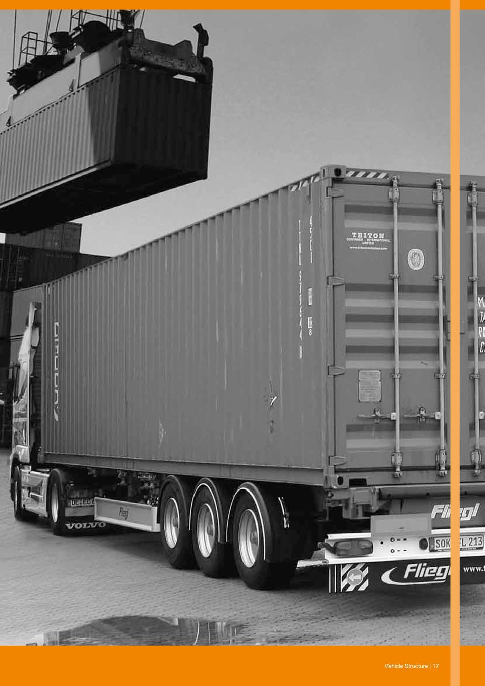
12 Chapter 2. Vehicle Structure Transport units, vehicles and swap bodies, should meet the requirements in accordance with the European standards EN 12642, EN and EN 283. The load securing arrangement in the different Cargo Transport Unit s (CTU) depends on the type of load as well as side walls, headboard and rear wall strength. Figure 4 compares strength requirements of CTU side walls, headboard and rear wall. The vehicle types marked in green have strong side walls, the yellow marked vehicles have sides for bottom blocking only and the sides of the red marked vehicles are to be regarded as weather protection only. Below the practical use of the different strengths are described. Note: that if the side walls are used for blocking of the load it is important that the specified number of laths in accordance with the test certificate are used. The laths are to be placed so that the load weight is uniformly distributed over the full length of the sides. BOX-TYPE VEHICLE COVER/STAKE VEHICLE CURTAINSIDER EN L Headboard: P = 40 % of payload, maximum 5 tonnes Rear wall: P = 25 % of payload, maximum 3.1 tonnes EN XL Headboard: P = 50 % of payload Rear wall: P = 30 % of payload Fig Vehicle Structure

13 2.1 Side walls Vehicles are grouped into the following categories depending on the strength in the side walls: EN L with strength 30 % of payload (0.3 P) EN XL with strength 40 % of payload (0.4 P) No strength at all; 0 % of payload Side walls - EN L If the side walls are built in accordance with EN L the side walls in a box trailer are able to take up 30 % of the payload (0.3 P) uniformly distributed over the full length and height. The design acceleration sideways is 0.5 g. Thus, if the friction factor is at least 0.2 the side walls are strong enough to withstand the sideway forces. Note that side walls in a curtainsider built in accordance with EN L is regarded as a weather protection only. Side walls - EN XL If the side walls are built in accordance with EN XL the side walls are able to take up 40 % of the payload (0.4 P) uniformly distributed over the full length and up to 75% of the height. The design acceleration sideways is 0.5 g. Thus, if the friction factor is at least 0.1 the side walls are strong enough to withstand the sideway forces. Note that curtain sides should be used with care if the forces from the load are not uniformly spread out over the sides. Side walls - No strength When the load is transported in a transport unit without strong sides, the whole load weight has to be secured against sideways movements by lashing in accordance with the Quick Lashing Guide. 2.2 Headboard The following strength in the headboard is possible: EN L with strength 40 % of payload (0.4 P), maximum about 5 tons (5000 dan) EN XL with strength 50 % of payload (0.5 P) Unmarked CTU or load not stowed tightly against the headboard, 0 % of payload The calculated friction factors are in accordance with EN :2010. Headboard - EN L Headboards built in accordance with EN L are able to withstand a force corresponding to 40 % of the vehicles payload (0.4 P) uniformly distributed over the full width and height. However, for vehicles with a payload of more than 12.5 tons, the strength requirement is limited to a force of 5 tons. With respect to this limit, figure 5, shows the load weight in tons that is permitted to be blocked against a headboard with a limited strength of 5 tons for different friction factors. If the load weight is larger than relevant table value additional lashings are required. Friction factor µ Load weight possible to block against the headboard in forward direction (tonne) Fig. 5. Load weight prevented from sliding by a L-headboard as function of the friction factor. Vehicle Structure 13
 uniformly distributed over the full length and height. The design acceleration sideways is 0.5 g. Thus, if the friction factor is at least 0.")
14 Headboard - EN XL If the headboard is built in accordance with EN XL the headboard is able to take up 50 % of the payload (0.5 P) uniformly distributed over the full width and up to 75% of the height. The design acceleration in forward direction is 0.8 g. Thus, if the friction factor is at least 0.3 the headboard is strong enough to withstand the forces in forward direction of a full payload. Headboard - No strength When the load is transported in a transport unit with a headboard with no strength or when it is not stowed tightly against the headboard the whole load weight has to be secured against forward movement by lashings in accordance with the Quick Lashing Guide. 2.3 Rear wall The following strength in the rear wall is possible: EN L with strength 25 % of payload (0.25 P), maximum about 3.1 tons (3100 dan) EN XL with strength 30 % of payload (0.3 P) Unmarked CTU or load not stowed tight against the rear wall, 0 % of payload The calculated friction factors are in accordance with EN :2010 Rear wall - EN L Rear walls built in accordance with EN L are able to withstand a force corresponding to 25 % of the vehicles payload (0.25 P) uniformly distributed over the full width height. However, for vehicles with a payload of more than 12.5 tons, the strength requirement is limited to a force of 3.1 tons. With respect to this limit, figure 6, shows the load weight in tons that is permitted to be blocked against a rear wall with a limited strength of 3.1 tons for different friction factors. If the load weight is larger than relevant table value additional lashings are required. Friction factor µ Load weight possible to block against the rear wall in towards the rear direction (tonne) Fig. 6. Load weight prevented from sliding by a L- rear wall as function of the friction factor Rear wall - EN XL If the rear wall is built in accordance with EN XL the rear wall is able to take up 30 % of the payload (0.3 P) uniformly distributed over the full width and up to 75% of the height. The design acceleration in towards the rear direction is 0.5 g. Thus, if the friction factor is at least 0.2 the rear wall is strong enough to withstand the forces in towards the rear direction of the full payload. Rear wall - No strength When the load is transported in a transport unit with a rear wall with no strength or when it is not stowed tightly against the rear wall, the whole load weight has to be secured against backward movement by lashings in accordance with the Quick Lashing Guide or to alternative instructions if equivalent safety could be verified. Securing against doors When doors are designed to provide a defined blocking resistance the doors may be considered as a strong load space boundary, provided the load is stowed to avoid impact loads to the doors and to prevent the load from falling out when the doors are opened. 14 Vehicle Structure

15 2.4 Stanchions Stanchions for roll-type loads, should provide transverse blocking against roll forces emanating from cylindrical packages. They should be designed so that, together, they can withstand a lateral force equivalent to 50% of the maximum load weight at half the load height (H/2) above the vehicle platform for road transport. Stanchions for other than roll-type loads should be designed so that, together, they can withstand a lateral force equivalent to 30% of the maximum load weight at half the load height (H/2) above the vehicle platform for road transport. Fig. 8. Lashing point H H/2 D=H P 2.6 ISO-Containers Fig. 7. Design of stanchions P=0.5 x maximum load 2.5 Lashing points Lashing points in load carriers should be placed in pairs, opposite each other, along the long sides with a spacing of m longitudinally and a maximum of 0.25 metres from the outer edge. Continuous lashing anchorage bars are preferable. Each lashing point should, as a minimum, be able to withstand the following lashing forces in accordance with standard EN 12640: Vehicle total weight (tonne) Strength of lashing point (dan) 3.5 to to over * *(in general dan is recommended) Fig. 9. ISO Containers Vehicle Structure 15

16 Chapter 2. Vehicle Structure End walls In accordance with the ISO standard , both the front and rear walls (rear doors) must withstand an internal load (force) equivalent to 40% of the maximum load weight, evenly distributed over the entire end wall/ door surface. 2.7 Swap bodies Sidewalls Sidewalls must withstand an internal load (force) equivalent to 60% of the maximum load weight, evenly distributed over the entire wall Attachment- and lashing points Each attachment point at the floor level shall be designed and installed in accordance with ISO standard which states that it shall provide a minimum rated load of 1,000 dan applied in any direction. Each lashing point in corner posts and at the roof shall be designed and installed to provide a minimum rated load of 500 dan applied in any direction. Fig. 10. Swapbody standing on landing legs The load force values for swap bodies are outlined in standard EN 283. This almost corresponds with the body structure standard for vehicles as specified in standard EN L (see section above). 16 Vehicle Structure
 equivalent to 60")
17 Vehicle Structure 17
18 Chapter 3. Packaging 3.1 Packaging materials Loads transported by road are often contained in packages. The CMR convention does not enforce packaging requirements, but relieves the carrier of his liability for loss or damage if the load is not properly packed. Depending on the type of product and the mode of transport, the main function of the packaging can be: weather protection supporting the product during loading and unloading preventing product damage enabling efficient load securing For large products (e.g. machinery) a dedicated packaging is used. This can be a platform to support the products and a cover that can be rigid or flexible. 3.2 Packaging test method For packages being bottom blocked only: The packaging can be considered as stable based on acceleration sideways and towards the rear if the package is able to withstand a tilt angle of at least 26.6 (rounded 27 ) without any significant deformation (Fig.11) The packaging can be considered as stable based on acceleration forward if the package is able to withstand a tilt angle of at least 38.7 (rounded 39 ) without any significant deformation Alternative test methods may be used if equivalent safety can be verified. Specific materials for transport packaging that can help to rigidify a load unit are described below. Shrink film stretch hoods stretch wrap film Pre stretched wrap film straps nets Fig. 11. Practical inclination tests sideways and lengthways 18 Packaging
 a dedicated packaging is used. This can be a platform to support the products and a cover that can be rigid or flexible. 3.")
19 Packaging 19

20 Chapter 4. Restraining Methods (securing methods and equipment) Restraining methods are principally the following: locking blocking direct lashing top-over lashing combinations of methods in conjunction with friction The restraining method(s) used should be able to withstand the varying climatic conditions (temperature, humidity etc) likely to be encountered during the journey. Annex II demonstrates several illustrations of securing methods and equipment. 4.1 Blocking Fig. 12. Blocking by headboard and sides Fig. 13. Blocking by headboard and specially designed gates Blocking or bracing means that the load is stowed to lie flush against fixed structures and fixtures on the load carrier. These may be in the form of headboards, sideboards, sidewalls or stanchions. The load can be stowed directly or indirectly by means of filling against the fixed blocking devices built into the load carrier, and these prevent any horizontal movement of the load. In practice it is difficult to achieve a tight fit against the blocking devices and a small clearance usually remains. Gaps must be kept to a minimum, especially those to the headboard. The load should be blocked against the head board either directly or by the use of filler material in between. Void spaces should be filled and may be favourably stuffed by empty pallets inserted vertically and tightened by additional timber battens as necessary. Material which may deform or shrink permanently, like rags of gunny cloth or solid foam of limited strength, should not be used for this purpose. Small gaps between unit loads and similar load items, which cannot be avoided and which are necessary for the smooth packing and unpacking of the goods, are acceptable and need not to be filled. The sum of void spaces in any horizontal direction should not exceed 15 cm height of standard pallet. However, between dense and rigid load items, such as steel, concrete or stone, void spaces should be further minimized, as far as possible. Reference to code of practice for packaging of cargo transport units (CTU Code) - IMO/ILO/UNECE. 20 Restraining Methods (securing methods and equipment)

21 4.1.1 Blocking with filler Effective securing of the load by blocking requires close stowage of the packages both against the load carrier s blocking fixtures and between the individual packages. When the load does not fill the space between the side and end boards, and is not otherwise secured the gaps must be filled with a filler material to create compressive forces that ensure a satisfactory blocking of the load. These compressive forces should be proportionate to the total load weight. Air cushions Inflatable air cushions are available both as disposable items and as recyclable products. The cushions are easy to install and are inflated by compressed air, often by means of an outlet in the truck s compressed air system. Suppliers of air cushions are expected to provide instructions and recommendations concerning load capacity and appropriate air pressure. For air cushions it is important to avoid damage as a result of wear and tear. Air cushions should never be used as filler against doors or any non rigid surfaces or partitions. Fig. 15. Air cushion in a vehicle of box type Fig. 14. Filler between the rows of load Examples of some possible filler materials are shown hereafter. When there are large gaps between the load and blocking fixtures, and high bracing forces, it is often appropriate to use blocking braces fitted with sufficiently strong wooden spacers. It is essential that blocking braces are fixed in such a way that the spacers are always at right angles to the load that is being braced. This will ensure that the blocking braces are more able to resist the forces exerted by the load. Goods pallets Goods pallets are often a suitable form of filler material. If this clearance towards the blocking is larger than the height of a EURO pallet (about 15 cm) then the gap could be filled with, for example, such pallets standing on end, for the load to be properly blocked. If the clearance towards the sideboards on any side of the load section is smaller than the height of a EURO pallet then the gap to the sideboard must be filled with suitable filling, for example planks of wood. Restraining Methods (securing methods and equipment) 21
22 Large empty spaces can alternatively be filled with empty pallets as shown below. If the packages are not sufficiently rigid and stable for threshold blocking, a corresponding blocking effect can be achieved by using panels consisting of boards or load pallets as shown in the figure below. Depending on the rigidity of the load packages, a blocking structure can be created to provide a large or small blocking surface. Fig. 18. Panel blocking in forward direction for the second layer Fig. 16. Blocking with pallets at rear Threshold blocking and panel blocking When there is a height difference between various layers, threshold blocking or panel blocking can be used for base blocking of the upper layer against the lower layer. Using some form of base material, such as load pallets, the load section is raised so that a threshold is formed, and the upper load layer is base blocked longitudinally. Fig. 19. Panel blocking of paper sheets on pallets Fig. 17. Threshold blocking of upper layer in forward direction When threshold or panel blocking is used at the rear, at least two sections of the bottom layer must be behind the blocking section. 22 Restraining Methods (securing methods and equipment)
23 4.1.3 Wooden battens nailed to the load platform On load carriers that have robust wooden platform beds of good quality, base blocking can be achieved by nailing wooden battens directly to the floor. The maximum closure force per nail can be found in the Quick Lashing Guide. For load securing with blocking only, it is recommended to have a height of about 50 mm Wedges Wedges can be used to prevent cylindrical objects moving along the loading platform (see figures 20 and 21). Wedges should have a minimum height of R/3 (one third of the roll radius) if there is no top-over lashing. If used in conjunction with top-over lashing, no more than 200 mm is required. Wedges should have an angle of about 37 toward the load, which is created out from the rectangular triangle whose sides are in the proportion 3, 4 and 5, where the 90 angle is upward. (Fig. 20). Fig. 21. Blocked wedges Lashing A lashing is a restraint device such as webbing, chain or wire rope that either ties load together or keeps load in contact with the load platform or any blocking device. Lashings should be positioned so that they are in contact only with the load to be secured and/or the securing points. They should not be bent over flexible items, side gates etc Top-over lashing Top-over lashing is a method of securing where lashings are positioned over the top of the goods in order to prevent the load section from tipping or sliding. If there is no side blocking at the bottom, for example top-over lashing can be used to press the load section towards the platform bed. Contrary to blocking, topover lashing forces the load against the load platform. Fig. 20. Wedge Even if there is neither sliding nor tipping risk, it is recommended to always use at least one top-over lashing with S TF 400 dan per every 4 tonnes of load or similar arrangement to avoid significant displacement for non-blocked load due to vibrations. Restraining Methods (securing methods and equipment) 23
24 Loop lashing Loop lashing is a form of sling lashing load to one side of the vehicle body, thereby preventing the load from sliding towards the opposite side. To achieve doubleaction lashing, loop lashings must be used in pairs, which will also prevent the load from tipping over. Two pairs of loop lashings will be required to prevent the load from twisting longitudinally. The loop lashing ability to sustain the required traction force depends upon the strength of the lashing points among other things. Fig. 22. Top-over lashing (75-90 ) Fig. 23a. Top-over lashing (30-75 ) THE LARGER THE ANGLE THE BETTER IT IS! BELOW 30 LIMITED EFFECT! Fig. 24. Loop lashing To prevent the load from moving in a longitudinal direction, loop lashing must be combined with base blocking. The loop is only providing lateral restraint, i.e. in a sideways direction. Fig. 23b Fig. 25. Loop lashing combined with base blocking 24 Restraining Methods (securing methods and equipment)
25 Spring lashing Spring lashing can be used to prevent tipping and/or sliding forwards or towards the rear. Spring lashing is a restraining method consisting of one or two slings over the corners of the load layer, the purpose of which is to prevent a load layer from tipping or sliding. Spring lashing may also be in the form of a single, closed round-sling, placed across the edge of the load layer and lashed by means of a diagonal lashing on each side. The angle to the load surface is measured in the longitudinal direction, and it is recommended that the angle is not more than 45. Fig. 28. Spring lashing preventing the goods section from sliding and tipping over in rear direction Round turn lashing Round turn lashing is, in combination with other forms of securing, a method to bind a number of packages together. Horizontal round turn load lashing is applied by binding a number of packages together in load sections and therefore reduces to some extent the risk of the load tipping over. Fig. 26. Example a spring lashing preventing forward movement Fig. 29. Horizontal round turn lashing of sections of load Fig. 27. Vertical round turn load lashing is used to bind a number of load items together to stabilise the load section and to increase vertical pressure between the layers. Risks of internal sliding are reduced. A diagonal lashing with corner strap must be calculated taking into account the angle, the friction and the lashing capacity (LC) given on the label of the lashing as required by standard EN :2010. Empty pallets holding up the lashing may be used as an alternative. Fig. 30. Vertical round turn lashing of load Restraining Methods (securing methods and equipment) 25
26 Direct lashing If the load is equipped with lashing eyes compatible with the strength of the lashing, it is possible to lash directly between the lashing eyes and the lashing points on the vehicle. Fig. 33. A combination of loop and spring lashings for steel coils Fig. 31. Direct lashing Combination of load securing methods To prevent sliding in longitudinal and transversal direction an arrangement with combined spring lashing, top-over or loop lashing and blocking as show in examples below and designed in accordance with the standard/quick Lashing Guide could be used Lashing equipment The choice of the best means of securing a load to a vehicle will depend on the type and composition of the load to be carried. Operators should equip the vehicle with the securing equipment appropriate for the types of load usually carried. If general loads are carried various types of securing equipment should be available. Web lashings made of man-made fibres (usually polyester) (see standard EN Part 2), Lashing chains (see standard EN ) or Wire lashing ropes (see standard EN ) are mainly used as lashing materials. They have a tag or label specifying the Lashing Capacity (LC) in deca-newtons (dan: the official force unit instead of kg) and the standard tension force (S TF ), which is obtained when a hand force (S HF ) of 50 dan is applied to the tensioner. Fig. 32. Combination of blocking and lashing Breaking Load 4000kg LC 1600 dan SHF 50 dan / STF 400daN 100% POLYESTER LGL 10m NOT FOR LIFTING IRU CIT VAT N XXXYYY-YYYY 2014 EN Fig. 34. Typical content of webbing strap label, marked in accordance with EN Restraining Methods (securing methods and equipment)
27 NOTE: Do not use mechanical aids such as levers, bars etc, unless the tensioning device is specially designed to be used with them. It is recommended to use legibly marked and labelled lashing equipment only. In some countries it is mandatory to have all lashings marked. Web lashings are often used for top-over (frictional) lashing, but may also be used for direct lashing (especially when the larger sizes of lashing are used). For goods with sharp edges and heavy goods such as machinery, steel, concrete, military hardware etc., lashing chains should be used. Chains should normally be used for direct lashing. Wire rope lashings are suitable for load such as wire mesh that is used for concrete reinforcing and certain types of timber loads, such as round logs stacked longitudinally. Lashings can be linked together, but combinations used in parallel should be of the same marking. They can be linked as round combinations or be fitted with end fittings for attachment to fixed devices such as rings, hooks, recesses etc. in the load carrier. For topover lashing with web lashings the tensioning device - a ratchet - shall achieve a pre-tension force of at least 10% of the lashing capacity (LC), at a hand force of 50 dan. The maximum authorised pre-tension force at 50 dan hand force is 50% of lashing capacity (LC) for all lashing equipment. All equipment used for securing loads should be regularly inspected for wear or damage. Inspection and maintenance arrangements should be in accordance with the manufacturers instructions. Special attention should be paid to webbing and rope to ensure that there are no major visible defects, such as fraying of the strands. They should also be inspected to ensure that they have not been otherwise contaminated, cut or damaged through misuse. Consult the lashing manufacturer or suppliers if there is any doubt as to whether repairs are required. Equipment made of steel should not be used if any part has got a permanent deformation such as a bent link on a chain or a bent part on the tensioner for a web lashing Webbing assemblies Webbing assemblies are suitable for securing many types of load. They usually consist of a webbing strap with some form of end fittings and incorporate a tensioning device. It is strongly recommended to use assemblies made in accordance with standard EN or equivalent. One way lashings are not covered by any standard so it is important to verify that they are of similar characteristics as standardised webbings. The tension force, which can be achieved by a hand force of 50 dan is given on the label as the standard tension force for the webbing assembly. Fig. 36. Ratchet Fig. 35. Damaged webbing should be replaced Restraining Methods (securing methods and equipment) 27
28 Chain lashing Two properties determine the strength of a chain: the thickness of the links and the quality of the metal used. Standard EN Load restraint assemblies on road vehicles Safety; Part 3: Lashing chains - gives the requirements for lashing chains. The chain used should be compatible with the requirements of the load carried. Where necessary strong packing or bevelled sections should be used on corners or sharp edges, which prevent damage to the chains and also increase the radius around which they bend thus increasing their effective strength. Fig. 37. Different types of ratchets Fig. 38. Webbing Webbing made from polyester, polyamide or polypropylene is available. Polyester loses a little strength when wet, is highly resistant to moderate strength acid but can be damaged by alkalis. Polyamide may lose up to 15% in strength when wet, is highly resistant to alkalis but can be damaged by moderate strength acids. Polypropylene is useful where chemical resistance is a requirement. Polyester straps are available in various sizes and their properties should be clearly marked in accordance with standard EN Before use, it should be verified that the metal parts are not corroded or damaged; the webbing is not cut or frayed and all stitching is sound. If any damage is found, advice should be sought from the manufacturer or suppliers. Fig. 39. Excavator diagonally lashed with chains Lashing chains shall never be used when knotted or connected with a pin or screws. Lashing chains and the edges of the loads shall be protected against abrasion and damage by using protective sleeves and/or corner protectors. Lashing chains showing any signs of damage must be replaced or returned to the manufacturer for repair. 50-mm wide reusable polyester straps with 1600 dan LC are normally used on heavy trucks. The maximum elongation is 7% at LC. 28 Restraining Methods (securing methods and equipment)
29 The following are considered to be signs of damage requiring the replacement of the faulty components: for chains: superficial fissures, elongation exceeding 3%, wear exceeding 10% of the nominal diameter, visible deformations for connecting components and tensioning devices: deformations, splits, pronounced signs of wear, signs of corrosion Repairs should only be carried out by the manufacturer or their agent. Following repair, the manufacturer shall guarantee that the original performance of the lashing chains has been restored. Any joining links in chains should always be inspected before use. Chains should only be used in conjunction with suitable tensioners and turnbuckles with a safe working load compatible with that of the chain. Below are examples of typical dimensions and strengths for Class 8 chains: Chain link diameter (mm) Break load (dan) Wire rope lashing Lashing Capacity (dan) Steel wire ropes are suitable for lashing load when used in a similar manner to chains. Single part wires should never be used for lashing as they cannot easily be assessed for serviceability and any failure will result in complete failure of the restraint. If bent over edges, ropes strength decreases depending on the bending diameter. For a rope to retain its full mechanical resistance, the diameter of the bend needs to be at least 6 times the diameter of the rope. As a rule of thumb, for smaller bending diameter, the strength is reduced by 10% for each unit under 6 (e.g. if the bending diameter equals 4 times the diameter of the rope, the rope strength is reduced by 20%; so the residual strength represents 80% of its nominal value). In any case, it must be considered that ropes laid over sharp edges only keep 25% of their normal strength. In addition, rope eyes should be squeezed with at least 4 clamps. With less clamps, the strength is reduced proportionally. The open end of an eye always should be opposite the screws. As a rule of thumb, the rope should be squeezed to half of its diameter. Wire and flat wire lashing ropes in addition to all connecting components shall be examined at regular intervals by a qualified person. The following are considered to be signs of damage: localised breaks; reduction by abrasion of the ferrule diameter by more than 5% damage of a ferrule or a splice visible wire breaks of more than 4 threads on a length of 3d, more than 6 threads on a length of 6d or more than 16 threads on a length of 30d (d=diameter of the wire) heavy wear or abrasion of the rope by more than 10% of the nominal diameter (mean value of two measurements at right angles) crushing of the rope by more than 15%, flaws and kinks for connecting components and tensioning devices: deformations, splits, pronounced signs of wear, signs of corrosion visible defects on the jaws of the rope pulley Wire lashing ropes with broken strands shall not be used. Wire lashing ropes shall only be used in a temperature range from -40 C to +100 C. At temperatures below 0 C, look for and eliminate icing on brake and traction rope of tensioning elements (winches, hoists). Care shall be taken that wire lashing ropes are not damaged by possible sharp edges of the load. Restraining Methods (securing methods and equipment) 29
30 Turnbuckle Turnbuckles are commonly used for both chains and lashing wire ropes (See standard EN ) provided with a thimble at each eye and a minimum of three or four separate U-bolt wire rope grips compliant to standard EN on each side. They must be secured against working loose and must be positioned so that bending is avoided. Fig. 40. Turnbuckle Turnbuckle with short handle to avoid overloading by 50 dan hand force (achieved tension should not be more than 50% of LC) Nets or covers with lashings Fig. 41. Load securing net Restraint system with integrated lashings can be used instead of a net. Nets used for securing or retaining certain types of load may be constructed from webbing straps or ropes of either natural or man-made fibres or steel wire. Webbing nets are generally used as barriers to divide the load space into compartments. Rope or cord nets may be used to secure loads either to pallets or directly to the vehicle as the primary restraint system. Lighter nets can be used to cover open vehicles and skips when the type of load does not require a cover sheet. Care should be taken to ensure that the metal parts of nets are not corroded or damaged, that the webbing is not cut and that all stitching is sound. Rope and cord nets should be checked for cuts or other damages to the fibres. If necessary, repairs must be carried out by a competent person before the net is used. The mesh size of the net must be smaller than the smallest part of the load. Fig. 42. Restraint system with integrated lashings 30 Restraining Methods (securing methods and equipment)
31 Ropes The use of ropes as a means for securing load is very questionable. If ropes are used for securing load, they should preferably be made from polypropylene or polyester. Polyamide (nylon) ropes are not suitable as they tend to stretch under load. Sisal or manila ropes are also unsuitable as their strength is reduced by water saturation. Ropes should be made of 3 strands and must have a minimum nominal diameter of at least 10mm. The ends of the rope should be spliced or otherwise treated to prevent fraying. Rope should be selected in relation to the maximum force to be imposed on each lashing. The manufacturer must indicate the maximum authorised load for these ropes on an attached label or sleeve. Knots and sharp bends will reduce the strength of a rope. Wet ropes should always be allowed to dry naturally Intermediate Blocking Bars Intermediate blocking bars are frequently used for load securing to the rear, particularly to secure load on partly loaded vehicles. Intermediate blocking boards are mounted onto the normal longitudinal laths or onto drop bars of curtainsiders or cover stake bodies. The maximum load bearing capacity needs to be checked on the manufacturer s information. Generally, intermediate blocking boards can withstand loads up to a maximum of 350 dan if mounted on wooden laths and 220 dan on aluminium laths Attaching rails for booms and lashings in sidewalls Sidewalls may have longitudinal rails with anchorage points, with each point usually designed to withstand a 2-tonne load in a longitudinal direction. Lashings and booms with suitable end fittings can be secured quickly and give effective blocking. This is an extremely effective method for rear blocking of remaining packages after partial unloading, but load concentration adjacent to fixing points should be avoided. Fig. 44. Intermediate blocking bars Fig. 43. Attaching rails Restraining Methods (securing methods and equipment) 31
32 4.2 Locking Freight containers, like ISO containers, swap bodies, etc., with a mass of more than 5.5 tonnes should only be carried on vehicles fitted with twist locks. Provided the twist locks are fully engaged and locked in position, the container will be adequately secured and no further restraint will be necessary. The twist locks must be maintained in a serviceable condition and a minimum of four should be used for each container carried. (ISO 1161 covers the specification for corner fittings for series 1 ISO freight containers). In most cases twist locks are fitted to the vehicle during manufacture but if fitted at a later stage, modifications to the chassis/structure must be carried out in accordance with the recommendations of the vehicle manufacturer. Twist locks should be regularly inspected for wear, damage and operation defects. Locking devices intended to prevent operating levers from moving during the journey should be given special attention. Fig. 46 & Fig. 47. Twist locks 4.3 Combination of restraining methods Combining two or more restraining methods is usually the most practical and cost efficient way for effectively securing load. For instance top-over lashing can be combined with base blocking. Fig. 45. Twist locks Care must be taken that the restraining forces from the combined restraining methods all apply concurrently and not one after the other. Each restraining method may be insufficient for safely securing the load if acting independently from the other(s). 32 Restraining Methods (securing methods and equipment)
33 4.4 Supporting equipment Friction mats Base material and spacers made of high friction material can be used to increase friction between the platform and the load, and also between load layers when required. There are different types of high friction material, for example carpets, rubber mats and sheets of paper (slip-sheets) covered with friction material. They are used in conjunction with other securing methods. The mats should have suitable properties (such as friction, strength, thickness, granularity, etc.) commensurate with the load (weight, surface, etc.) and environmental conditions (temperature, humidity, etc.) likely to be encountered during the journey. This should be verified with the manufacturer. The use of slip inhibiting material allows for the reduction in the number of lashings required. Very often the material is used as square pieces, cut off in strips of 0,5 to 1,0 m length and 150, 200 or 250 mm width. The thickness ranges from 3 to 10mm. If used carefully, such pieces may be reused several times, but they cannot fulfil their function if they become greasy. Load has to be lowered into place upon these materials since it is not possible to slide the load into position Wood runners Load sections with many rows and layers, such as sawn timber, must often be stabilised by means of cross bracing. Wood runners with square cross section are not suitable, because they may rotate in service. The width/height ratio of the cross section should be at least 2:1. Fig. 48. Friction mats WOOD RUNNERS Fig. 50. Sawn timber stabilised with wood runners Fig. 49. Friction mats Fig. 51. Secured full load of sawn timber Restraining Methods (securing methods and equipment) 33
34 4.4.3 Shrink film and stretch film Steel or plastic band straps Steel or plastic band straps are suitable for binding heavy and rigid goods, such as iron and steel products, to a pallet. They require special tensioners and cannot be re-tightened. Disposable (suitable for single use due to their one way operation) steel straps may be used for securing loads onto pallets. The pallets and load must additionally be secured to the vehicle, either by blocking or lashing. These one-way straps are not suitable to secure loads directly to the vehicle as internal tensions can build into the fixing to the vehicle and into the seals during the journey, making the removal of the steel straps hazardous. One-way steel straps that have been cut open and lie on the ground represent a tripping and cutting danger. When webbing straps are used to secure goods bound with steel straps, care must be taken to ensure that the steel straps cannot cut into the webbing straps. Fig. 52. Packaging with stretch film Small packages may easily and effectively be secured to the load pallets by means of a stretch film. A stretch film is easy to apply and the desired rigidity of form is achieved for the entire pallet load by using an appropriate number of wraps. With shrink film a plastic hood is placed over the wrapped pallet load, which is then heated to make plastic shrink and therefore make the load more rigid. Fig. 53. Band straps In open load carriers the use of steel straps is a common cause of injuries as loose ends of the straps may protrude from the sides of the carrier during transport. 34 Restraining Methods (securing methods and equipment)
35 4.4.5 Edge beams Supporting edge beams are designed to be structurally rigid (stiffened against bending) and have a right angle profile. They are used for distributing the forces from top-over lashings to the load sections and can be made of wood, aluminium or similar material of sufficient strength Edge protectors to prevent damage to load and lashing equipment Edge protectors made of wood, plastic, light alloy metal or other suitable material are used for distributing the lashing force to prevent the lashings from cutting into the load, and also for binding short ends. Edge beams provide the same or even better edge protection, but are rigid in design and therefore distribute the force from the lashings. For that purpose it is essential that edge protectors have low friction properties on the webbing face so the straps can easily slide and distribute the lashing force. On the other hand, it is in some cases advisable to use high friction edge protectors to reduce the risk of tipping. Fig. 54. Edge beam made of aluminium Fig. 55. Edge beam made of wood Fig. 56. & Fig. 57. Edge protectors to protect load and lashing Restraining Methods (securing methods and equipment) 35
36 4.4.7 Protective spacers If sharp edges can damage the cargo, use some form of protective material (see also Section 4.1.1: Blocking with filler). Tag washers should never be used in connection with dangerous goods. Tag washers usually have a round or rectangular form 50 to 130 mm side or diameter (see picture below). Fig. 59. Tag washers Fig. 58. Protective spacers Tag washers Double-sided tag washers are suitable for holding various layers together in a load row. Tag washers are available in different sizes. Tag washers can only be used with soft materials (wood etc) and should completely enter the material. There is no standard for tag washers, but some experience guide values are shown in quick lashing guide. A minimum of two tag washers has to be used. To enter into wood, a minimum of 180 dan on each tag washer is needed. Do not use too many tag washers! Friction mats (see section 4.4.1) can be an alternative to tag washers. NOTE: As tag washers are not visible once the load covers them their function is not controllable. Also be aware that the tag washers may damage the platforms surface and the load. The use of friction mats instead of tag washers is preferable. 36 Restraining Methods (securing methods and equipment)
37 Restraining Methods (securing methods and equipment) 37
38 Chapter 5. Calculations The required number of lashings for any given load, should be calculated based on the algorithms of EN :2010. By using the Quick Lashing Guide in Annex III the securing arrangement fulfils the requirement in EN :2010 with a safety margin as the quick lashing guide is a simplification. 5.1 Example When load securing arrangements are designed by calculations and/or practical tests the methods described in the standard EN :2010 should be used. In such cases a documentation outlining the basis for number of lashings used for the particular load should be prepared and made available during the transport. It is recommended to secure the load as usual and then check by the help of the tables in the quick lashing guide if the applied securing arrangement is sufficient to prevent sliding and tipping of the load in all directions. In many cases calculations can be avoided. For example, in case of blocking the load in all directions, as per manufactures instructions, in an XL coded vehicle and equipped as per certificate, no further securing is required if the friction factor between the loading platform and the load is 0.3 or higher, even for a full truck load. If calculations are necessary, they should be done in accordance with the standard EN :2010. Alternatively load securing arrangements can be tested in accordance with the instructions in the standard EN :2010. In case two or more securing methods are combined, the formulas described in the standard EN :2010 may be used in combination for calculation as described in the example right Wooden crate low centre of gravity Calculate the maximum allowed weight of the wooden box loaded on a trailer in accordance with the figure below by the help of tables in the quick lashing guide as well as the formulas in the standard EN :2010 to avoid sliding and tipping sideways, forward and towards the rear. The trailer has an ordinary plyfa floor that is swept clean and is free from frost, ice and snow. The trailer is built in accordance with the standard EN 12642, class XL and the lashing points on the trailer are designed in accordance with the standard EN 12640, each with an LC of 2000 dan. The transverse distance between the lashing points is about 2.4 m. The box is made of sawn wood and it has the following dimensions; length x breath x height = 7.8 x 1.0 x 1.0 m. The center of gravity is located in the geometrical center of the box. The box is secured by two top-over lashings and one spring lashing applied in forward direction. The lashings have an LC of 1600 dan and are pre-tensioned to 400 dan. The spring lashing is fixed to the trailer about 2 m behind the forward part of the box and the lashings thus have the following approximate angles: The top-over lashings; vertical lashing angle between the lashings and the platform α 55. Spring lashing: Vertical lashing angle between the lashing and the platform α 25 and the horizontal angle between the lashing and the longitudinal axle of the vehicle β 19. Fig. 60. A wooden box with low centre of gravity 38 Calculations
39 Sliding The friction factor µ between the box of sawn wood and the plyfa floor of the trailer is 0.45 in accordance with annex B of the standard Example of Load prevented from sliding by two top-over lashings Quick Lashing Guide By the tables for top-over lashings in the quick lashing guide in Annex III it can be seen that one top-over lashing prevents 6.4 tonnes from sliding sideways, 0.81 tonne from sliding forward and 6.4 tonnes from sliding towards the rear. These values are valid for a vertical lashing angle of degrees. As the angle is about 55 degrees the lashing prevents half the load weight from sliding only. With two lashings the load weight m in tonne prevented from sliding in the different directions by the two top over lashings is thus: Sideways: 6.4 tonnes Forward: 0.81 tonnes Towards the rear: 6.4 tonnes Formulas in the standard By the standard EN :2010 the load weight m prevented from sliding by the two top-over lashings is calculated by the help of equation 10 (EQ10) of the standard. EQ10, where: m = the load weight. The weight is obtained in kg if F T is given in Newton (N) and in tonne if F T is given in kilo Newton (kn). 1 dan = 10 N and 0.01 kn. n = 2; number of top-over lashings µ = 0.45; friction factor α = 55 ; vertical lashing angle in degrees F T = S TF = 400 dan = 4 kn g = 9.81 m/s 2, the gravity acceleration c x,y = 0.5 sideways, 0.8 forward and 0.5 towards the rear, the horizontal acceleration coefficient c z = 1.0; the vertical acceleration coefficient f s = 1.25 forward and 1.1 sideways and towards the rear; safety factor By these values the load weight m in tonne prevented from sliding in the different directions by the two top over lashings is: Sideways: 10.9 tonnes Forward: 1.4 tonnes Towards the rear: 10.9 tonnes Load weight prevented from sliding forward by the spring lashing Quick Lashing Guide From the tables for spring lashings in the quick lashing guide it can be seen that one spring lashing prevents 6.7 tonnes of load from sliding in forward direction. This is valid if the vertical lashing angle is maximum 45 degrees and the lashing is directed almost in parallel with the vehicle s side. With a longitudinal lashing angle β of 19 degrees the table value should be reduced by 15% to 5.7 tonnes. Formulas in the standard The load weight m prevented from sliding in forward direction by the spring lashing can alternatively be calculated by equation 35 (EQ35) of the standard. The influence of the spring lashing to prevent transverse sliding is neglected. EQ35, where m = the load weight. The weight is obtained in kg if F T is given in Newton (N) and in tonne if F T is given in kilonewton (kn). 1 dan = 10 N and 0.01 kn. n = 1; number of spring lashings F R = LC = 1600 dan = 16 kn µ = 0.45; friction factor f µ = 0.75; safety factor α = 25 ; vertical lashing angle in degrees β = 19 ; horizontal lashing angle in degrees g = 9.81 m/s 2, the gravity acceleration c x = 0.8; the horizontal acceleration coefficient in forward direction c z = 1.0; the vertical acceleration coefficient By these values the load weight m in tonne prevented from sliding in forward direction by the spring lashing is 7.1 tonnes. Calculations 39
40 Example of Load prevented from sliding by two top-over lashings and the spring lashing Quick Lashing Guide The previous calculations give that the two top-over lashings and the spring lashing can prevent the following cargo weight from sliding: Sideways: 6.4 tonnes Forward: = 6.5 tonnes Towards the rear: 6.4 tonnes The maximum load weight prevented from sliding by the actual securing arrangement is thus 6.4 tonnes. Formulas in the standard The above calculations give that the two top-over lashings and the spring lashing can prevent the following load weight from sliding: Sideways: 10.9 tonnes Forward: = 8.5 tonnes Towards the rear: 10.9 tonnes The maximum load weight prevented from sliding by the actual securing arrangement is thus 8.5 tonnes Tipping The stability of the box is checked by equation 3 (EQ3) of the standard. EQ3, where: b x,y = 0.5 sideways, 3.9 forward and 3.9 towards the rear; the horizontal distance from the centre of gravity and the tipping point in each direction c x,y = 0.5 sideways, 0.8 forward and 0.5 towards the rear; the horizontal acceleration coefficient c z = 1.0; the vertical acceleration coefficient d = 0.5; the vertical distance from the centre of gravity to the tipping point By these values it can be concluded that the box is stable in all directions and no lashing is required to prevent tipping. This can also be seen by the tables in the quick lashing guide with H/B = 1.0/1.0 = 1.0 and H/L = 1.0/7.8 = Conclusion The maximum allowed load weight of the box secured by two top-over lashings and one spring lashing is thus 6.4 tonnes to prevent sliding and tipping in all directions if the tables in the quick lashing guide are used and 8.5 tonnes if the formulas in the standard are used Wooden crate high center of gravity Calculate the maximum allowed weight of the wooden box loaded on a trailer in accordance with the figure 61 by the help of the formulas in the standard EN :2010 to avoid sliding and tipping sideways, forward and towards the rear. The trailer has an ordinary plyfa floor that is swept clean and is free from frost, ice and snow. The trailer is built in accordance with the standard EN 12642, class L and the lashing points on the trailer are designed in accordance with the standard EN 12640, each with an LC of 2000 dan. The transverse distance between the lashing points is about 2.4 m. The wooden box is made of sawn wood and it has the following dimensions; length x width x height = 7.8 x 1.0 x 2.4 m. The center of gravity is located in the geometrical center of the box. The box is secured by two top-over lashings and one spring lashing applied in forward direction. The lashings have an LC of 2000 dan and are pre-tensioned to 500 dan. The spring lashing is fixed to the trailer about 2.5 m behind the forward part of the box and the lashings thus have the following approximate angles: The top-over lashings; Vertical lashing angle between the lashings and the platform α 74. Spring lashing: Vertical lashing angle between the lashing and the platform α 43 and the horizontal angle between the lashing and the longitudinal axle of the vehicle β Sliding The friction factor µ between the box of sawn wood and the plyfa floor of the trailer is 0.45 in accordance with annex B of the standard. 40 Calculations
41 Fig. 61. Example of Load prevented from sliding by two top-over lashings The load weight m prevented from sliding by the two top-over lashings is based on equation 10 (EQ10) of the standard. EQ10, where Example of Load prevented from sliding forward by spring lashing The cargo weight m prevented from sliding in forward direction by the spring lashing is based on equation 35 (EQ35) of the standard. The influence of the spring lashing to prevent transverse sliding is neglected. EQ35, where m = the load weight. The weight is obtained in kg if F T is given in Newton (N) and in tonne if F T is given in kilonewton (kn). 1 dan = 10 N and 0.01 kn. n = 2; number of top-over lashings µ = 0.45; friction factor α = 74 ; vertical lashing angle in degrees F T = 500 dan = 5 kn g = 9.81 m/s 2, the gravity acceleration c x,y = 0.5 sideways, 0.8 forward and 0.5 towards the rear; the horizontal acceleration coefficient c z = 1.0; the vertical acceleration coefficient f s = 1.25 forward and 1.1 sideways and towards the rear; safety factor By these values the load weight m in tonne prevented from sliding in the different directions by the two top over lashings is: Sideways: 16.0 tonnes Forward: 2.0 tonnes Towards the rear: 16.0 tonnes m = the load weight. The weight is obtained in kg if F T is given in Newton (N) and in tonne if F T is given in kilonewton (kn). 1 dan = 10 N and 0.01 kn. n = 1; number of spring lashings F R = LC = 2000 dan = 20 kn µ = 0.45; friction factor f µ = 0.75; safety factor α = 43 ; vertical lashing angle in degrees β = 16 ; horizontal lashing angle in degrees g = 9.81 m/s 2, the gravity acceleration c x = 0.8; the horizontal acceleration coefficient in forward direction c z = 1.0; the vertical acceleration coefficient By these values the load weight m in tonne prevented from sliding in forward direction by the spring lashing is 8.2 tonnes. Calculations 41
42 Example of Load prevented from sliding by two top-over lashings and spring lashing The above calculations give that the two top-over lashings and the spring lashing can prevent the following load weight from sliding: Sideways: 16.0 tonnes Forward: = 10.2 tonnes Towards the rear: 16.0 tonnes The maximum load weight prevented from sliding by the actual securing arrangement is thus 10.2 tonnes Tipping The stability of the box is check by equation 3 (EQ3) of the standard. EQ3, where b x,y = 0.5 m sideways, 3.9 m forward and 3.9 m towards the rear; the horizontal distance from the center of gravity and the tipping point in each direction c x,y = 0.5 sideways, 0.8 forward and 0.5 towards the rear; the horizontal acceleration coefficient c z = 1.0; the vertical acceleration coefficient d = 1.2 m; the vertical distance from the center of gravity to the tipping point By these values it can be concluded that the box is stable in forward and towards the rear direction but not sideways Load weight prevented from tipping sideways by two top-over lashings The effect of the spring lashing preventing sideways tipping is neglected and the load weight m prevented from tipping by the two top-over lashings is based on equation 16 (EQ16) of the standard. For one row and the center of gravity located in the geometrical center, the load weight can be calculated by equation 16: EQ16, where m = the load weight. The weight is obtained in kg if F T is given in Newton (N) and in tonne if F T is given in kilonewton (kn). 1 dan = 10 N and 0.01 kn. n = 2; number of top-over lashings F T = S TF = 500 dan = 5 kn or = 0.5 x LC = 1000 dan = 10 kn α = 74 ; vertical lashing angle in degrees g = 9.81 m/s 2, the gravity acceleration c y = 0.5 calculated with F T = S TF or 0.6 calculated with F T = 0.5 x LC; the sideways horizontal acceleration coefficient h = 2.4 m; the height of the box w = 1.0 m; the width of the box c z = 1.0; the vertical acceleration coefficient fs = 1.1; safety factor sideways By these values the load weight m in tonne prevented from tipping sideways is the lowest of 8.9 and 8.1 tonnes. Thus the two top-over lashings can prevent 8.1 tonnes from tipping sideways Conclusion The maximum allowed load weight of the box secured by two top-over lashings and one spring lashing is thus 8.1 tonnes to prevent sliding and tipping in all directions. 42 Calculations
43 Calculations 43
44 Chapter 6. Check of load securing 6.1 Classification of deficiencies Deficiencies may be classified into one of the deficiency groups: Minor deficiency: A minor deficiency exists when the load has been properly secured but a safety advice might be appropriate Major deficiency: A major deficiency exists when the load has not been sufficiently secured and a significant shifting or overturning of the load or parts thereof is possible Dangerous deficiency: A dangerous deficiency exists when traffic safety is directly endangered due to a risk of loss of load or parts thereof or a hazard deriving directly from the load or an immediate endangering of persons When several deficiencies are present, the transport is classified in accordance with the highest deficiency group. If, in the event that there are several deficiencies, as the effects based on the combination of these deficiencies are expected to reinforce one another, the transport shall be classified in the next higher deficiency level. 6.2 Methods of inspection The method of inspection is a visual assessment of the proper use of appropriate measures in necessary amount to secure load and/or measurement of tension forces, calculation of securing efficiency and checking of certificates where appropriate. A quick inspection should include a check of: the load and individual load units securing equipment and materials securing methods In cases, where a load securing certificate is available, the inspection shall be limited to check whether the load securing is in line with the instruction in the certificate issued by a competent person. Every inspection can be summarised in the following checklist that links the deficiencies to the load, to the vehicle and to the securing methods. Deficiencies related to the load related to the vehicle and the equipment related to the securing method a. Transport packaging does not allow proper load securing b. One or more load units are not properly positioned a. The vehicle is not suitable for the load b. Obvious defects of the vehicle superstructure c. Certificates of vehicle parts that are effectively used, are not available, are false or show insufficient strength d. Securing equipment that is effectively used, does not conform to the relevant standards a. Securing is not sufficient, but can be corrected b. Securing is not sufficient and can not be corrected with equipment available c. Expert advice is required to assess the effectiveness of the load securing system 44 Check of load securing
45 Check of load securing 45
46 Chapter 7. Examples of Specific Good Practices In addition to the requirements of the Quick Lashing Guide and the calculation methods of the standard EN :2010, the arrangements below, based on practical experience, may be used for specific products. Furthermore alternative instructions/advice can be used if equivalent safety could be verified. 7.1 Panels stowed on platform with A-frames Panels of concrete, glass or wood etc. may be stowed on a platform using A -trestles. The trestles will additionally need to be secured on the loading platform. The trestle should be of adequate strength and prevented from sliding and tipping in relation to the vehicle platform. 7.2 Timber loads This section provides general guidance on measures for the safe carriage of timber, both round and sawn timber. Timber is a live commodity, which can lead to independent movement of parts of the load if the restraint is inadequate. It is essential that timber is not loaded to a height, or in such a way, as to result in the likelihood of either the vehicle or load becoming unstable. Sawn Timber Sawn timber is usually transported in standard packages complying with ISO 4472 and related standards. Be aware if not proven otherwise that in general any plastic covering on the timber will lower the coefficient of friction and more lashings may be required. These packages are generally strapped or wired at each end and before loading the straps should be checked for safety. If the straps are damaged or insecure extra care must be taken to ensure that the complete load is adequately secured to the vehicle. Packages of sawn timber should preferably be transported on loading platforms equipped with centre stanchions. Fig. 62. Insert blocking device in between panels stowed on a platform 3 Where centre stanchions are used each section should be secured for sideways movement by: At least two stanchions if the length of the section is 3.3 m or below At least three stanchions if the length of the section is above 3.3 m In addition to the centre stanchions each section should be secured by at least three top over lashings with a pretension of at least 400 dan and an LC of at least 1600 dan. In longitudinal direction the packages should be secured as any type of load. If centre stanchions are not available and where the packages are properly and rigidly bundled, the packages can be secured as any type of load. Fig. 63. Panels secured on a platform with blocking device in place Guidance for calculating the required number of lashings is found in Annex III. 46 Examples of Specific Good Practices
47 and the rear support (bolster) is not recommended, it is safer to transport it longitudinally (lying along the length of the vehicle) in several sections, each individually supported by upright supports (stanchions). Fig. 64. Stacked Longitudinally Each outer log or piece of timber shall be restrained by at least two upright supports (stanchions). The strength of the stanchions shall be sufficient to prevent the vehicle from being over width after having been exposed to a side acceleration of 0.5 g. Any timber that is shorter than the distance between two stanchions should be placed in the centre of the load and all logs should preferably be laid top to tail alternately to ensure an evenly balanced load. Where timber is supported by two pairs of stanchions, the ends of the timber should extend at least 300 mm beyond the stanchions. The centre of either top of the outside timbers must be no higher than the stanchions. The top of the middle timbers must be higher than the side timbers to crown the load and enable it to be properly tensioned by the lashings, as illustrated below: Fig. 65. Round Timber The general principles of load distribution should be adhered to, and it is important to ensure that, whenever possible, the load is blocked against the headboard. The use of chain or web lashings with tensioner is recommended and all lashings should be checked and kept tight during the whole transport operation. All lashings shall have an LC of at least 1600 dan with a pretension of at least 400 dan. It is recommended to use self-tensioning tensioner. The load and lashings should especially be checked before passing from a forest road to public highway. The transporting of timber stacked transversely (lying across the vehicle) supported by the front headboard Fig. 66. Load lashing should always add vertical load on round timber In front of the first section of the timber - between the driver cab and the timber - a headboard should be fitted in accordance with standard EN class XL and the load should be no higher than the headboard. Top-over lashings creating a vertical pressure on the timber should be tightened over each load section (timber pile) in the following numbers: a) Timber with bark: At least one lashing per load section up to a maximum length of 3.3 m. Two lashings if load section longer than 3.3 m. b) Timber with bark removed: At least two lashings per load section. Examples of Specific Good Practices 47
48 The top-over lashings should be placed - transversely - between each load section s front and rear pairs of side stanchions as symmetrically as possible. Long poles The carriage of long poles is a very specialised field of timber haulage that is generally accomplished using pole vehicles or vehicles where the timbers are secured to a trailing dolly at one end. Vehicles should be fitted with bolsters and stanchions of sufficient strength to restrain the load. Chains or web lashings are necessary for securing the load and generally a minimum of three chains or web lashings should be used, one of which should bind together any overhanging tails or the middle of an awkwardly shaped load. It should be possible to tighten the lashings using a toggle or load binder. Fig. 67. Fig. 70. Transport of long poles Fig. 68. Example of a round timber vehicle equipped with stanchions Stacked transversely Timber stacked transversely across a flatbed vehicle cannot be adequately secured by conventional restraining methods. Passing straps or chains from the front of the vehicle across the top of the timber to the rear with cross straps is not considered to be an acceptable load securing method. If timber is carried transversely then suitable side gates must be used and the load should not be higher than the side gates. 7.3 Large containers or large and heavy packages ISO-containers and similar load carriers with anchorage points for twist locks or similar locking mechanisms should preferably always be transported on loading platforms with container locks. However large containers for road transport, with or without load, can alternatively be secured with lashing and blocking in accordance with the principles of the standard EN :2010. Fig. 69. Timber stacked transversely is not recommended! 48 Examples of Specific Good Practices
49 7.4 Trucks and trailers Trucks and trailers should only be carried on vehicles suitable for that purpose. This will include having appropriate lashing points in terms of number, position and strength. In general the securing arrangements should follow the same basic principles as suggested for the carriage of off-road vehicles, but the following additional points should also be addressed: The truck or trailer should be carried with the parking brake engaged Steering wheel lock must be active and preferably with the wheels chocked The vehicle transmission should be engaged in lowest possible gear; where applicable The chocks should be securely attached to the carrying vehicle s deck The carriage of laden vehicles is not recommended but if this is necessary then extra attention should be paid to the resultant higher centre of gravity of the carried vehicle and the possible resulting loss of stability when cornering or braking. It may also be necessary to put extra lashings onto the chassis of the truck or trailer being carried to pull it down on its springs and hence help to avoid an unstable load. All loose equipment on the trucks or trailers being carried, and on the carrying vehicle, should be securely stowed. If more than one trailer is carried in piggyback fashion then each trailer should be lashed to the one on which it rests and then all those carried should be lashed to the carrying vehicle (see picture below). The truck or trailer being carried should be positioned so that its weight is fully supported by the carrying vehicle. If necessary, spreader plates should be used to avoid high localised loadings that may be caused by the landing legs of a semi-trailer for example. The restraint provided by the friction between the tyres and the deck with the parking brake on will not be sufficient to prevent movement. The truck or trailer being carried should be lashed to the carrying vehicle using appropriate lashing equipment. A tensioning device should be used in each lashing and the lashings used to restrain the fore and aft movement should be set at an angle of less than 60 from the horizontal to obtain the maximum effect. The lashings should be tested for adequate tension after the vehicle has travelled a few miles and again at intervals during the journey and be re-tensioned if necessary. Fig. 71. Trailers loaded on a trailer Lashing should be secured onto parts of the trucks or trailer s axles or chassis that are rated for the purpose. Care should be taken to avoid straining or damaging the other vehicle components such as brake pipes, hoses, electrical cables etc., through lashing over or near them. Examples of Specific Good Practices 49
50 7.5 Transport of cars, vans and small trailers 4 These vehicles should preferably be secured by using a combination of both lashing and blocking. The lashing guidelines underneath do not take into account the orientation of the vehicle on the transporting vehicle. The loading deck pillars, the ropes and the supports of the safety ropes should be cushioned to secure damage free opening of the vehicle doors The manufacturer may require inspecting new transporters and/or transporter types before approving them as suitable for the transport of his cars. The details of any such requirement must be clearly stated in the contractual agreement Equipment Car transporter equipment Special car transporters must be equipped with: two sets of ramps of approximately cm 3-4 chocks per transported vehicle 1-2 lashing straps per transported vehicle. Lashing straps must be 2.2 m long and stretch maximally by 4%. Moreover, they must be equipped with movable ( sock type) strap control and meet the norm DIN EN The label on the lashing must not be washed out to a point when it becomes impossible to read (the norm must be clearly visible) Car transporters Only special car transporters may be used for transporting cars; they must be in good condition, painted and rust-free The hydraulic systems must be functioning properly and not leaking The transporters should be equipped with stone guards above the wheels The surface of the decks and ramps must offer firm hold without sharp edges Loading ramps must be placed at a sufficiently low angle to enable easy access and prevent damage to the underbody of the transported vehicles. The recommended maximum ramp angle is 8 degrees The upper deck of a special car transporter must be equipped with safety ropes in conformity with the local legal requirements Loading and unloading of car transporters The rules that follow are specific to the loading/ unloading process. Still, the rules on car handling listed in the general section (Section 1.2.) also apply. Personnel must also be trained on these instructions before being allowed to proceed with loading, unloading or other handling When loading, adapt the loaded weight, height and length to the national requirements and to the chosen routes Before loading or unloading The transporter must be parked on level and firm ground The loading decks must be freed of all lashings, chocks, tools or other objects. It is forbidden to let lashings pending on the anti-fall guard (safety ropes) The decks of the truck and the trailer must be fixed in a suitable position for loading vehicles without causing damage to their under body All gaps in the decks (wheel indents) must be covered with track sections. The decks of the truck and the trailer must be bridged with connecting ramps During loading or unloading Cars must be driven onto/from the transporters at walking speed to reduce the probability of causing damage. Speed must be particularly reduced before driving onto or off the ramps 4 ECG OPERATIONS QUALITY MANUAL; 50 Examples of Specific Good Practices
51 Cars must be unloaded only under motor power. It is strictly forbidden to push the vehicles off the transporter, to brake with the hand brake or the clutch! It must be checked that the following distances are kept (to be measured with one s hand): Between the cars, bumper to bumper: a fist (approximately 10 cm) Between the car s roof and the upper deck: a fist (approximately 10 cm) Between overlapping vehicles: a fist (approximately 10 cm) Between a car on the truck and another on the trailer, bumper to bumper: 2 fists (approximately 20 cm) Between the car s underbody and the deck: 3 fingers (5cm absolute minimum) After loading or unloading Cars with manual transmission must be left in first gear and with the handbrake (parking brake) applied. Cars with automatic transmission must be left with the transmission selection lever in P position and the handbrake (parking brake) applied If the cars have been loaded/unloaded during the night or under any other conditions that demand the use of headlights, they have to be switched off immediately after loading/ unloading Cars must be locked during transport. Keys must be secured by the driver Cars must be lashed for transport in accordance with the lashing procedures exposed in the next section Lashing Fig. 72. Three point lashing straps with strap control in combination with wheel chocks must be used. The use of wheel chocks is not necessary if wheels are secured in troughs or chambers that are openings in the ramps/decks which serve for fixing the wheels. The wheel shall enter into the trough/chamber by ca. 1/6 of its diameter Fig. 73. Fig. 74. Fig. 75. Strap over a sleeve, no direct contact on the tyre Lashing has to proceed as follows: Anchor the first hook to the transporter deck (lashing bar) in such a way that the strap runs as vertically as possible. Then tie the strap round the wheel, making sure that the strap control is positioned correctly Anchor the second hook to the transporter deck (lashing bar) Anchor the third hook at the anchor point lying laterally away from the wheel and tighten the strap using the ratchet Examples of Specific Good Practices 51
52 7.5.4 Securing of vehicles loaded in the direction of the traffic One wheel chock in front and one behind either rear wheel Additionally secure this rear wheel by means of a three point lashing Diagonally to this wheel place one wheel chock in front of the respective front wheel If wheel chocks cannot be used for technical reasons, an additional wheel must be secured with a lashing strap Additional securing of vehicles loaded rearmost in an angled position The rearmost vehicle loaded behind the trailer s rear axle or on single car transporter, behind the rear axle of the truck, shall be additionally secured at the wheels of the rearmost axle by means of two wheel chocks and one lashing strap each. Fig. 78. Fig Securing of vehicles loaded in the direction opposite to the traffic One wheel chock in front and one behind either rear wheel Diagonally to this wheel place one wheel chock in front of and one behind the respective front wheel Additionally secure both wheels by means of one three point lashing each If wheel chocks cannot be used for technical reasons, an additional wheel must be secured with a lashing strap Fig Securing vehicles on the top deck In case a vehicle cannot be secured with wheel chocks or lashing belts within the protected area of the top deck, either one of the following must be done: The loading platform shall be lowered to allow performing of this work from the ground The wheels of one axle of the vehicle within the protected area shall be secured by means of two wheel chocks and one strap on each side If wheel chocks cannot be used for technical reasons, an additional wheel must be secured with a lashing strap. Fig Examples of Specific Good Practices
53 7.6 Steel and aluminium coils These vehicles should preferably be secured by using a combination of both lashing and blocking. The lashing guidelines underneath do not take into account the orientation of the vehicle on the transporting vehicle. The vehicle should be in such a condition that work can safely be executed. For example the boards of the loading platform of the vehicle should not be damaged. The general equipment should be available as a minimum; for the transport of special steel products it should supplemented with additional equipment. Both are specified below and considered hereafter in this chapter. For any steel product the following general equipment should be available as a minimum: safe headboard securing points loading platform securing devices Equipment for special cases: groove(s) for coils (cross-)beam or H-beam wedge bed cover Special provisions Groove A groove is recommended for coils of 4 tonnes or more and mandatory for coils of 10 tonnes or more. For coils of 4 to 10 tonnes a wedge bed may also be used (see Wedge bed hereafter). Requirements for a groove are: the slopes should have an angle of 35 degrees to the horizontal the coils, if placed in the groove, should have a minimum clearance of 20mm to the bottom Furthermore: the width/height ratio of the coils should not be lower than 70% if lower than 70%, the coils have to be stowed against a support rule of thumb: width of groove = at least 60% of coil diameter the contact area of the coil should clearly be below the top of the groove Diameter of the coil 35 degrees Minimum clearance 20mm Depth of the groove Width of the Characteristics of a groove Fig. 80. Examples of Specific Good Practices 53
54 (Cross-)beam or H-beam The use of a (cross-) beam is highly recommended as it is a good device to fix coils. It is used both for coils bore horizontal in a groove and for coils bore vertical on a pallet. There are different good constructions for a (cross-) beam. The example of a (cross-) beam given below has protection strips (in this case synthetic) on the touch side of the (cross-) beam. Fig. 81. Fig. 82. Example of a (cross)beam for blocking of coils Wedge bed A wedge bed is a construction for a coil with bore horizontal: the wedges on which the coil rests ought to go over the whole width of the coil there should be a provision to fix the spacing between the wedges of the wedge bed stable support and free space under the coil similar as for the groove-method use of anti-slip mats between the wedge bed and loading platform highly recommended Cover When products have to remain dry during the transport, they should be covered in such a way that they stay dry under all weather conditions If a cover is used it must able to be removed without hampering the (un)loading operation The cover should be at least 10 cm above the load and should not touch it The cover should not be damaged (e.g. being torn), to avoid the risk of leaks Diameter of the coil Minimum distance supports: 0,6 diameter of 35 degrees Minimum clearance 20mm Loading platform Characteristics of a wedge bed Fig Examples of Specific Good Practices
55 Examples of Specific Good Practices 55
56 Chapter 8. Training in loading and load securing in Cargo Transport Units (CTUs) 8.1 Qualification of participants Persons responsible for planning and supervision of loading and securing should be fully knowledgeable about all technical, legal and commercial requirements of this task and about all inherent risks involved. They should know the customary terminology in order to communicate effectively with consignors, carriers, forwarders and loaders. Personnel engaged in loading and securing should be trained and skilled to do this work and understand the relevant terminology in order to follow with the instructions of supervisory personnel. They should be aware of the specific risks associated with the assigned loading operation. Persons responsible for planning and supervision of loading and securing as well as personnel responsible for the actual loading and securing should receive appropriate instruction, information and training for their specific tasks before they commence loading operations. The management of a facility where CTUs are loaded and secured is responsible to ensure that all personnel involved in the loading and securing of load in CTUs or in the supervision thereof are adequately trained and appropriately qualified, commensurate with their assigned roles and responsibilities. 8.3 Training All persons should receive instruction, information and training on safe loading and securing practices, commensurate with their duties. The training should be designed to provide an appreciation of the consequences of badly loaded and secured load in CTUs, the legal requirements, the magnitude of forces which may act on load during road, rail and sea transport, as well as basic principles of loading and securing of loads in CTUs. All persons should receive detailed training concerning specific requirements for the transport, loading and securing of load in CTUs which are applicable to the functions that they perform. Such training should be followed by a sufficient period of practical assistance to experienced loaders. The competency of any person to be employed in work involving the loading and securing goods in CTUs should be verified or appropriate training provided. This may be supplemented by periodic training, as deemed appropriate by the regulatory authority. Topics for consideration, to be included in the training as appropriate, are specified in annex I. 8.2 Regulatory authorities The regulatory authority may establish minimum requirements for training and, where appropriate, qualifications for each person involved, directly or indirectly, in the loading and securing of load in CTUs, particularly in relation to dangerous loads. Regulatory authorities involved in the development or enforcement of legal requirements relating to the supervision of the safety of the transport by road, rail and sea should ensure that their personnel are adequately instructed, informed and trained, commensurate with their assigned roles and responsibilities. 56 Training in loading and load securing in Cargo Transport Units (CTUs)
57 Training in loading and load securing in Cargo Transport Units (CTUs) 57
58 Annex I. Topics to be included in a training programme 5 Topics to be included in a training programme 1 Consequences of badly loaded and secured load Injuries to persons and damage to the environment Damage to chips and CTUs Damage to load Economic consequences 2 Liabilities Different parties involved in load transport Legal responsibility Goodwill responsibility Quality assurance 3 Forces acting on the load during transport Road transport Rail transport Sea transport 4 Basic principles for loading and securing Prevention from sliding Prevention from tipping Influence of friction Basic principles for load securing Dimensions of securing arrangements for combined transport 5 CTUs types Containers Flats Swap bodies Road vehicles Rail-cars/wagons 6 Load care consciousness and planning Choice of transport means Choice of CTU type Check of CTU prior to loading Load distribution in CTUs Requirements from the consignor of load regarding load loading Condensation risks in CTUs Symbols for load handling 7 Different methods for loading and securing Lashing Blocking Increasing friction 8 Equipment for securing and protection of load Fixed equipment on CTUs Reusable load-securing equipment One-way equipment Inspection and rejection of securing equipment 5 Reference to code of practice for packaging of cargo transport units (CTU Code) - IMO/ILO/UNECE 58 Topics to be included in a training programme
59 9 On completion of loading Closing the CTU Marking and placarding Dangerous Goods. Documentation Verifying gross mass consignor. 10 Loading and securing unitised load Cases Palletised loads Bales and bundles Bags on pallets Big bags Flexible Bulk Containers Slabs and panels Barrels Pipes Cartons 11 Loading and securing of non-unitized load Different types of packaged loads loaded together loading of heavy and light loads together loading of rigid and non-rigid loads together loading of long and short loads together loading of high and low loads together loading of liquid and dry loads together 12 Loading and securing of paper products General guidelines for the loading and securing of paper products Vertical rolls Horizontal rolls Sheet paper on pallets 13 Loading and securing of load requiring special techniques Steel coils Cable drums Wire rolls Steel slabs Steel plates Big pipes Stone blocks Machines 14 Loading and securing of dangerous goods Regulations for the transport of dangerous goods Definitions Packing/loading regulations Packing/Loading, separation and securing Labelling and placarding Information transfer when transporting dangerous goods Liabilities Topics to be included in a training programme 59
60 Annex II. Several illustrations of securing methods and equipment The arrangements below showed example of securing methods in different directions. Forward, towards the rear and sideways directions are illustrated separately, and should be combined depending on the properties of the CTU and the load. 1. In forward direction 1.1. Blocking in forward direction in XL vehicles Fig. 84.Fig. 85. Fig. 86.Fig. 87. Fig. 88.Fig. 89. Fig. 90.Fig Several illustrations of securing methods and equipment
61 1.2 Lashing to prevent movement in forward direction of non full layers Fig. 92. Fig. 93. Fig. 94. Fig Towards the rear 2.1 Blocking towards the rear Fig. 96. Fig. 97. Fig. 98. Fig. 99. Several illustrations of securing methods and equipment 61
62 Fig Fig Fig Fig Lashing preventing movement towards the rear Fig Fig Fig Fig Several illustrations of securing methods and equipment
63 3 Sideways 3.1 Blocking in sideways direction in XL vehicles Fig. 108.Fig Fig Fig Fig Fig Several illustrations of securing methods and equipment 63
64 3.2 Lashing in sideways direction Fig. 114.Fig Fig Fig Fig Fig Several illustrations of securing methods and equipment
65 Several illustrations of securing methods and equipment 65
66 Annex III. Quick Lashing Guide on safe load securing for road transport This guide offers practical instructions for securing loads in accordance with the European standard EN :2010. All values in the tables are expressed as a round number of 2 digits. In the tables on pages no risk means that there is no risk of the load sliding or tipping. Conditions for securing with this guide The best option for load securing... Where possible blocking should be used as method to secure the load Blocking involves positioning the load, or parts of the load directly to the headboard, sideboards, stanchions, supports, walls or parts of the load to stop it from moving. 6 sections The load must be prevented from sliding and tipping when exposed to forces occurring during transport. The securing of load must be done using locking, blocking, lashing or a combination of these techniques. Lashing equipment Values in this guide have been calculated on the assumption that the; 2 rows... lashing points resist 2000 dan (2 tonnes under stress)... webbings have a Lashing Capacity (LC) of 1600 dan (1.6 tonnes under stress)... webbings with S TF = 400 dan (tightened to 400 kg). The straps must be tightened to a minimum of 400 kg throughout the transport. If the load is blocked to a sufficient height, this will effectively stop it from sliding and tipping. If the load is only bottom blocked, lashing may be needed to prevent tipping. See the tipping tables on pages Quick Lashing Guide
67 Headboard and rear wall Headboards and rear walls on vehicles with a payload over 12.5 tonnes built in accordance with EN L. Headboard - EN L Friction factor, µ Rear wall - EN L 4 inch (4 ) nail Load weight (in tonnes) possible to block against the headboard in forward direction 0,15 7,8 0,20 8,4 0,25 9,2 0,30 10,1 0,35 11,3 0,40 12,7 0,45 14,5 0,50 16,9 0,55 20,3 0,60 25,4 Friction factor, µ Load weight (in tonnes) possible to block against the rear wall towards the rear 0,15 9,0 0,20 10,5 0,25 12,6 0,30 15,8 0,35 21,0 0,40 31,6 If the weight of the load is greater than that shown in the tables, then in addition to blocking, lashing will be required. These values are taken from the IMO Model Course 3.18 and recalculated in accordance with EN : Load weight in tonnes where one nail will stop sliding movement µ Sideways Forwards Towards the rear each side, 4 nail 4 nail 4 nail Plain Galvi- Plain Galvi- Plain Galvinised nised nised 0,2 0,36 0,53 0,18 0,26 0,36 0,53 0,3 0,55 0,80 0,22 0,32 0,55 0,80 0,4 1,1 1,6 0,27 0,40 1,1 1,6 0,5 no risk no risk 0,36 0,53 no risk no risk 0,6 no risk no risk 0,55 0,80 no risk no risk 0,7 no risk no risk 1,1 1,6 no risk no risk Unlashed loads and the risk of movement If there is no risk of a load sliding or tipping (as shown in the tables of this guide) the load can be transported without the use of lashing straps. If there is a risk that an unlashed load will move in transit because of vibration and the load is not blocked appropriately, then it must be secured using an alternative means. Other ways to secure a load Loads can also be secured by using friction or lashing methods. Calculation for lashing requirements If lashing are used to stop the load from moving, then; 1. Calculate the number of lashing straps needed to prevent a sliding movement. 2. Calculate the number of lashing straps needed to prevent the loads from tipping. 3. The highest number of these two values shows the minimum number of lashing straps needed. Supporting edge profile In some cases, less lashing straps than the number of sections of the load can be used. Each section of the load must be secured. A supporting edge profile may be used to spread the effects of each lashing. These profiles may be constructed of wooden planks (at least 25mm x 100mm). Other material with the same strength values can also be used, such as aluminium or similar material. At least one lashing strap should be used, for every 2nd section of the load, with one at each end. Quick Lashing Guide 67
68 Sliding The friction between the load and the loading platform (or load beneath it) has a huge influence on how much one lashing can hold. The table below gives the typical friction factors for common combinations of materials contacting each other or the vehicle load platforms. The values in the table are valid only when the contact surfaces are clean, undamaged and without frost, ice or snow. If this is not the case, then a friction factor (μ) = 0,2 must be used. Special precautions shall be taken if the surfaces are oiled or greasy. Tipping To find out the maximum load weight prevented from tipping, refer to the tables on pages in this guide. The H/B (height divided by the breadth) or H/L (height divided by the length) of load to be secured must be calculated. The calculations must be rounded up to the nearest higher value shown in the tables. Load items with the centre of gravity close to their centre The following sketches explain how to measure the H(height), L(length) and B(breadth) of the load. The values in this table are for both dry and wet surfaces. H Single load item Combination of materials Friction in the contact surface factor, µ Sawn wood Sawn wood fabric base laminate/plywood...0,45 Sawn wood grooved aluminium...0,40 Sawn wood shrink film...0,30 Sawn wood stainless steel sheet...0,30 Combination of materials Friction in the contact surface factor, µ Plane wood Plane wood fabric base laminate/plywood... 0,30 Plane wood grooved aluminium...0,25 Plane wood stainless steel sheet...0,20 Plastic pallet Plastic pallet fabric base laminate/plywood...0,20 Plastic pallet grooved aluminium...0,15 Plastic pallet stainless steel sheet...0,15 B L A section of the load (showing 3 rows and 2 layers) Load items with displaced centre of gravity If the load item to be secured has a centre of gravity above its centre or out to the side, then the H, B and L measurements should be done as shown in the diagram below. H = Distance up to the centre of gravity B = Shortest distance between the centre of gravity and the sideways tipping point L = Distance according to the diagram. H B L Steel and metal Steel crate fabric base laminate/plywood... 0,45 Steel crate grooved aluminium... 0,30 Steel crate stainless steel sheet...0,20 Concrete Concrete rough sawn wood battens...0,70 Concrete smooth sawn wood battens... 0,55 Anti-slip material Rubber...0,60 Other material... According to certificate H B L forwards L towards the rear 68 Quick Lashing Guide 9 TYA, 2014
69 Top-over lashing Using the table below, you must note that the angle between the lashing and the loading platform is of great importance. The tables should be used for angles between 75 and 90. If the angle is between 30 and 75 double amount of lashing straps are needed, or you halve the table values. If the angle is less than 30, then another method of securing the load must be used Goods weight in tonnes where one top-over lashing strap will stop sliding movements µ Sideways Forwards Towards the rear 0,15 0,31 0,15 0,31 0,20 0,48 0,21 0,48 0,25 0,72 0,29 0,72 0,30 1,1 0,38 1,1 0,35 1,7 0,49 1,7 0,40 2,9 0,63 2,9 0,45 6,4 0,81 6,4 0,50 no risk 1,1 no risk 0,55 no risk 1,4 no risk 0,60 no risk 1,9 no risk 0,65 no risk 2,7 no risk 0,70 no risk 4,4 no risk Sideways H/B 1 row 2 rows 3 rows 4 rows 5 rows H/L 0,6 no risk no risk no risk 5,8 2,9 0,6 no risk no risk 0,8 no risk no risk 4,9 2,1 1,5 0,8 no risk no risk 1,0 no risk no risk 2,2 1,3 0,97 1,0 no risk no risk 1,2 no risk 4,1 1,4 0,91 0,73 1,2 no risk no risk 1,4 no risk 2,3 0,99 0,71 0,58 1,4 5,3 no risk 1,6 no risk 1,5 0,78 0,58 0,49 1,6 2,3 no risk 1,8 no risk 1,1 0,64 0,49 0,42 1,8 1,4 no risk 2,0 no risk 0,90 0,54 0,42 0,36 2,0 1,1 no risk 2,2 4,5 0,75 0,47 0,37 0,32 2,2 0,83 7,2 2,4 3,3 0,64 0,42 0,33 0,29 2,4 0,68 3,6 2,6 2,4 0,56 0,37 0,30 0,26 2,6 0,58 2,4 2,8 1,8 0,50 0,34 0,28 0,24 2,8 0,51 1,8 If you need more than one lashing strap for each section of the load, then tensioning devices should be placed alternately on both sides. Loop lashing Load weight in tonnes where one top-over lashing strap will stop tipping motion Forwards Towards the rear 3,0 1,4 0,45 0,31 0,25 0,22 3,0 0,45 1,4 3,2 1,2 0,41 0,29 0,24 0,21 3,2 0,40 1,2 The calculation values for movement forwards and towards the rear assume that lashing straps are spread equally on each section of the load. A loop lashing will secure a load item on each side with a pair of webbings. At the same time the load will be prevented from tipping. At least two loop lashings per load item should be used. If the load item contains more than one section and the sections support each other and stop any twisting from occurring, then only one loop lashing per section of the load, may be needed. Quick Lashing Guide 69
70 The The values in in these tables will will apply only when each end of of the loop lashing strap is is fastened at at different lashing points. If If both ends of of a loop lashing are fastened to to the same lashing point, then this point must hold 1.4 x x lashing LC. Spring lashing Load weight in tonnes where one loop lashing will stop sliding movement µ Sideways µ Sideways 0,15 4,7 0, ,20 5,4 0,50 no risk 0,25 6,2 0,55 no risk 0,30 7,3 0,60 no risk 0,35 8,7 0,65 no risk 0, ,70 no risk Load weight in tonnes where one loop lashing will stop tipping motion Sideways H/B 1 row 2 rows 3 rows 4 rows 5 rows 0,6 no risk no risk no risk 6,5 4,1 0,8 no risk no risk 5,6 3,1 2,3 1,0 no risk no risk 3,1 2,0 1,6 1,2 1,2 no risk 4,6 2,1 1,5 1,3 1,4 1,4 no no risk 3,0 1,6 1,2 1,0 1,6 1,6 no no risk 2,2 1,3 1,0 0,86 1,8 1,8 no no risk 1,8 1,1 0,86 0,74 2,0 2,0 no no risk 1,5 0,94 0,75 0,65 2,2 2,2 5,1 5,1 1,2 0,83 0,67 0,58 2,4 2,4 3,7 3,7 1,1 1,1 0,74 0,60 0,53 2,6 2,6 2,9 2,9 0,96 0,66 0,54 0,48 2,8 2,8 2,4 2,4 0,86 0,86 0,61 0,50 0,44 3,0 3,0 2,0 2,0 0,78 0,78 0,56 0,46 0,41 3,2 3,2 1,8 1,8 0,72 0,72 0,51 0,51 0,43 0,38 A spring lashing is used to stop movement of a load item forwards and/or towards the rear. It is important that the angle between the loading platform and the lashing strap does not exceed 45. Max 45 Max 45 The spring lashing can be done in many ways. However, if the lashing is not applied to the upper edge of the load item, the tipping limits of the load weight is reduced. For example, if the spring lashing is placed half way up the load item, then it will only secure half the load weight indicated in the table. This spring lashing set-up This spring lashing set-up has two legs on each side, has two legs on each side, which secures twice the which secures twice the weight that is indicated in the weight table. that is indicated in the table. Max Max Load weight in tonnes where one spring lashing will stop sliding movement µ Forwards Towards the rear 0,15 3,7 6,6 0,20 4,1 7,6 0,25 4,5 8,8 0,30 4,9 10 0,35 5,4 12 0,40 6,0 15 Load weight in tonnes where one spring lashing will stop tipping motion H/L Forwards Towards the rear 1,2 no risk no risk 1,4 54 no risk 1,6 26 no risk 1,8 19 no risk 2,0 15 no risk 2, , , , ,0 9,9 28 3,2 9,5 25 Direct lashing Lashings must be fixed within the green angles, as shown in the diagram. This will ensure that they secure the individual load item in accordance with the table values. µ Forwards Towards the rear 0,45 6,7 19 0,50 7,5 no risk 0,55 8,4 no risk 0,60 9,6 no risk 0,65 11 no risk 0,70 13 no risk If the angle sideways exceeds 5 the table values must be reduced with: Angle % Angle % o o o o Left and Left right and lashings right lashings The areas where you can attach lashing straps are limited Left Left by two straight lines lashings lashings running diagonally through the centre of gravity at an angle Right Right lashings of 45. lashings 60 o 30 o 60 o 30 o 70 Quick Lashing Guide
71 Load weight in tonnes where one direct lashing strap will stop sliding movement µ Sideways Forwards Towards the rear 0,15 1,5 0,82 1,5 0,20 1,8 0,95 1,8 0,25 2,2 1,1 2,2 0,30 2,6 1,3 2,6 0,35 3,3 1,4 3,3 0,40 4,2 1,7 4,2 Load weight in tonnes where one direct lashing strap will stop tipping motion Other lashing equipment µ Sideways Forwards H/B Sideways H/L Forwards Towards the rear 1,2 no risk 1,2 no risk no risk 1,4 no risk 1,4 8,2 no risk 1,6 no risk 1,6 3,8 no risk 1,8 no risk 1,8 2,6 no risk 2,0 no risk 2,0 2,0 no risk 2,2 4,1 2,2 1,7 13,0 2,4 3,2 2,4 1,5 6,9 2,6 2,6 2,6 1,4 4,9 2,8 2,3 2,8 1,2 3,9 3,0 2,0 3,0 1,2 3,3 3,2 1,9 3,2 1,1 2,9 If the LC for a chain is not 0,45 5,4 1,9 5,4 0,50 no risk 2,2 no risk 0,55 no risk 2,6 no risk 0,60 no risk 3,0 no risk 0,65 no risk 3,5 no risk 0,70 no risk 4,2 no risk Values known, for LC and S TF are marked on the lashing If the the LC LC for can a chain be set is to not 50% equipment. of the breaking load. known, the LC can be set to 50% of the breaking load. If the LC for a chain is not known, the LC can be set to 50% If the LC of for the a chain breaking is not load. known, the LC can be set to 50% of the breaking load. Towards the rear Recalculating If equipment with a different capacity to LC 1600 or S TF 400 are used, the figures in the sliding and tipping tables have to be multiplied with the following factors. When recalculating, never use larger LC or S TF than the lashing points can hold. Methods Top-over lashing Actual For sliding: S TF Actual S = Multiplication factor 400 TF Actual S = Multiplication factor 400 TF = Multiplication factor Actual S400 For tipping TF = Multiplication the smallest factor of the following factors 400 shall be used: Actual S TF Actual LC or TF Actual LC = Multiplication factor Actual 400 S TF Actual or 1600 LC or = Multiplication = factor factor Actual S 400 TF Actual LC or = Multiplication factor Loop lashing Spring lashing Direct lashing Actual LC Actual 1600LC Actual 1600LC 1600 Actual LC Actual 1600LC Actual 1600LC 1600 Actual LC Actual 1600LC Actual 1600LC 1600 Loads consisting of several layers = Multiplication factor = Multiplication factor = Multiplication factor = Multiplication factor = Multiplication factor = Multiplication factor = Multiplication factor = Multiplication factor = Multiplication factor Determination of the number of top-over lashing straps needed to secure loads items stowed in several layers when they are not blocked sideways. Using the following four steps 1. Calculate the number of lashing straps needed to secure the weight of the whole section from sliding using friction in the bottom. 2. Calculate the number of lashing straps needed to secure the weight of the upper section from sliding, using friction between the upper and lower layer. 3. Calculate the number of lashing straps needed to stop tipping of the whole section. 4. The highest number of lashings from the three calculations should be used. Quick Lashing Guide 71
72 of load tipping) 0,5 (0,6 when risk of load tipping) 0,5 The load securing arrangement must carry ,8 of the cargo weight forwards... 0,5 of the cargo weight sideways and towards the rear... 0,6 of the cargo weight sideways if there is risk of the load tipping. 0,5 (0,6 when risk of load tipping) 0,8 Rolling goods You must prevent rolling goods from moving by using wedges or similar restraints. Non-rigid goods If the goods are not rigid, then more load restraints will need to be used than is shown in this guide. 0,5 (0,6 when risk of load tipping) 0,5 72 Quick Lashing Guide
73 The Vocational Training and Working Environment Council TYA Box 1826, Solna, Sweden Telephone Fax Load secured according to the table values A N G L E S F O R T O P - 60 O V E Direct lashing 45 Spring lashing 90 Load secured using either double lashing amounts or half of the table values R L A S H I N G 30 Direct/ Spring lashing Another method of load securing must be used Quick Lashing Guide 73
74 Annex IV. Safe load securing checklist Stay safe and compliant! Correct loading and securing of goods on road vehicles is essential to ensuring safe road transport. It is important that the securing of goods on a vehicle is carried out in accordance with recognised standards, and in compliance with relevant national legal requirements for road traffic, road safety and worker protection. In order to improve load safety in practice, the IRU has developed this checklist of harmonised tips for safe loading and load securing. Before loading a vehicle Make sure that the vehicle(s), if applicable, is suitable for transport of the specified load. Determine the number and type of lashings and/or chains to best secure the load. Determine the number of anti-slip mats and other securing materials (pallets, edge protectors, etc) to best secure the load. While loading and securing the load Make sure that the load platform and the vehicle s bodywork are clean, in good condition and free from defects. Load in accordance with the 18t 18t allowed vehicle weight. Determine the optimal loading equipment for the intended load. Load cargo in accordance with the allowed vehicle axle-load distribution. Determine the best method(s) to secure the defined load (blocking, direct lashing, top-over lashing, or combinations of method. Arrange load and/or its individual units optimally (lighter goods at the top, heavier on the bottom. Load in accordance with the planned unloading sequence. 74 Safe load securing checklist
75 While loading and securing the load During the journey Avoid unnecessary space between individual load units. When appropriate, check the load securing arrangements at periodic intervals during the journey. Check that the securing arrangements distribute the forces exerted by the load as evenly as possible. If emergency braking or another abnormal condition occurs during the journey, check the load at the nearest safe place. Check that all lashings are affixed to optimise angles. Each time a load unit is unloaded, redistributed, or loaded, adapt and recheck the load securing arrangement. Check that the securing equipment and materials are in good condition and free from defects. Drive smoothly and anticipate traffic situations to avoid any sudden change of direction or heavy braking. Check that the securing equipment and materials display legible and correct markings. This checklist is provided to you by the IRU Academy, the training arm of the International Road Transport Union (IRU). See our training programmes on Check that securing arrangements do not damage the load and that the load does not damage the securing arrangements. Safe load securing checklist 75
76 International Road Transport Union Headquarters 3, rue de Varembé B.P. 44 CH-1211 Geneva 20 Switzerland Tel: Fax: Web: The IRU International Guidelines on Safe Load Securing for Road Transport was made in partnership with: 2014 IRU I-0323 (en)
European Best Practice Guidelines on Cargo Securing for Road Transport
 European Best Practice Guidelines on Cargo Securing for Road Transport EUROPEAN COMMISSION DIRECTORATE-GENERAL FOR ENERGY AND TRANSPORT Preface by Mr Jacques Barrot, Vice-President of the European Commission,
Contents. Cargo securing instructions
 GENERAL CARGO SECURING GUIDELINES FOR PULP AND PAPER PRODUCTS Transport on road accordiing tto tthe European sttandard EN 12195 1::2010 Contents Page 1. INTRODUCTION AND PREAMBLE... 3 2. BASIC CARGO SECURING
How To Ensure Safety Of Lifting Equipment
 1 of 12 2 of 12 CONTENTS 1.0 OBJECTIVES... 3 2.0 SCOPE... 3 3.0 DEFINITION OF TERMS... 3 3.2.1 Loose Lifting Tackle... 3 3.2.2 Examination... 4 3.2.3 Inspection... 4 4.0 RESPONSIBILITIES & AUTHORITIES...
Road Regulations. Regulations for External Road Transport of Steel Products
 Road Regulations Regulations for External Road Transport of Steel Products Tata Steel Mainland Europe Revision 5.0 EN Logistics & Transport - Outbound Department Date : 01/08/2011 Valid until 01/08/2013
Standard 10 Cargo Securement
 Standard 10 Cargo Securement Standard 10: Cargo Securement June 2013 10-1 The NSC Standard 10 Cargo Securement was approved by the Council of Ministers Responsible for Transportation and Highway Safety
Cotton Australia Module Restraint Guide 2012 Edition
 Cotton Australia Module Restraint Guide 2012 Edition Last Updated: January 2013 INTRODUCTION The safe loading and transport of cotton modules is vitally important in preventing injury to module transport
Safety of Loads on Vehicles
 CODE OF PRACTICE Safety of Loads on Vehicles Third edition TSO: London Following the reorganisation of the government in May 2002, the responsibilities of the former Department for Transport, Local Government
Slings, Rigging and Lifting Equipment
 A printed or saved copy is an UNCONTROLLED copy. Check that it is the latest available version before use. Title: Number: SLINGS, RIGGING AND LIFTING EQUIPMENT GM-11-038-02 Version Number: 13.0 Date Revised:
SAFE USE OF LADDERS AND STEP LADDERS
 SAFE USE OF LADDERS AND STEP LADDERS HEALTH & SAFETY UNIT REVIEWS SPRING 2006 CONTENTS 1. INTRODUCTION...1 2. SAFE SYSTEM...1 4. SAFE USE OF LADDERS...3 4.1 Leaning ladders...3 4.2 Extension ladders...3
Industrial Guideline nr. 2
 Industrial Guideline nr. 2 OFFSHORE CONTAINERS Purpose Provide guidance for the safe use of offshore containers in the Dutch mining industry taking in account Dutch legislation and European standards.
Road Regulations. Regulations for External Road Transport of Steel Products
 Road Regulations Regulations for External Road Transport of Steel Products Tata Steel Supply Chain Mainland Europe Revision 5.1 EN Outbound Department Date : 14/01/2013 Valid until 01/08/2013 Blank page
I BEAM TRACK INSTALLATION
 PDQ 0/700 FESTOON SYSTEM INSTALLATION AND MAINTENANCE INSTRUCTIONS INTRODUCTION The PDQ Festoon System was designed to run on one of three sizes of I-beams: S x., S8 x 8. and S x.. System trolleys must
CERTIFICATE NAME OF PRODUCT MANUFACTURER PRODUCT DESCRIPTION CERTIFICATION PROCEDURE. No VTT C-6044-10 Date of issue 11.10.2010, Updated July 1, 2011
 CERTIFICATE NAME OF PRODUCT No VTT C-6044-10 Date of issue 11.10.2010, Updated July 1, 2011 H-CONTROL REFLEX+ reflective insulating vapour control layer for roof and wall applications MANUFACTURER ACTIS
39HQ Airovision Air Handling Units
 39HQ Airovision Air Handling Units Mounting instructions CONTENTS 1 - TRANSPORT AND LIFTING INSTRUCTIONS... 3 1.1 - General... 3 1.2 - Transport and storage... 3 1.3 - Roof edge protection during transport
M113 VEHICLE FAMILY RUBBER TRACK INSTALLATION INSTRUCTIONS SOUCY TRACK SYSTEM 04-M113-1ENS (SPLIT IDLER) Litho d in Canada 1 04-M113-1ENS
 Litho d in Canada 1 04-M113-1ENS") M113 VEHICLE FAMILY RUBBER TRACK INSTALLATION INSTRUCTIONS (SPLIT IDLER) 1 # TABLE OF CONTENTS List of parts and tools................................................3 Installation of complete kit...................................................5
M113 VEHICLE FAMILY RUBBER TRACK INSTALLATION INSTRUCTIONS (SPLIT IDLER) 1 # TABLE OF CONTENTS List of parts and tools................................................3 Installation of complete kit...................................................5
Installation guide for the SafeLine type anchorage device. Tested in compliance with EN 795: 1996. No.: SE-...
 Installation guide for the SafeLine type anchorage device Tested in compliance with EN 795: 1996 No.: SE-... Version: 09.10.2008 SE 67 Subject to technical alterations! Contents 1. General information
Walking and Working Surface Checklist:
 Walking and Working Surfaces Purpose: This information is presented to improve the level of safety in our operations, and to inform you that we will comply with the OSHA Standard 29 CFR 1910.23. Responsibility:
ENGLISH FORK GUIDE 2013
 FORK GUIDE 2013 ENGLISH 1 With a brand which is synonymous with specialists in forest products handling attachments, BOLZONI AURAMO offers its expertise and market leading attachments for all requirements,
SAFE HANDLING OF PRECAST CONCRETE PRODUCTS
 SAFE HANDLING OF PRECAST CONCRETE PRODUCTS Safety Handling of Precast Concrete Products The lifting of any precast product requires the use of special equipment and substantial planning and knowledge.
INSTALLATION. General. Important Note. Design. Transport
 General The roof trusses you are about to install have been manufactured to precise engineering standards. To ensure that the trusses perform as designed, it is essential that they be handled, erected
RZ Guardrail System Installation Manual
 TM RZ Guardrail System Installation Manual RZ Guardrail System Compliance is based on OSHA standards: (Standards - 29 CFR) 1910.23 (e) and (Standards - 29 CFR) 1926.502 (b) Failure to read, understand
C O N V E Y O R C O M P O N E N T S C H A I N S B E L T S B E A R I N G S
 C O N V E Y O R C O M P O N E N T S C H A I N S B E L T S B E A R I N G S January 2009 Issue 6 Valu Guide Brackets The Ultimate in Adjustability and Cost Savings Valu Guide brackets are part of a family
Safe handling when securing loads on trucks
 Guidance Note Safe handling when securing Advice for road transport operators and workers who use side-gates, side-curtains, restraint lashings and lashing tensioners December 2010 Background When loading
2.0 External and Internal Forces act on structures
 2.0 External and Internal Forces act on structures 2.1 Measuring Forces A force is a push or pull that tends to cause an object to change its movement or shape. Magnitude, Direction, and Location The actual
FALL PROTECTION PROGRAM
 FALL PROTECTION PROGRAM DEPARTMENT OF RISK MANAGEMENT AND SAFETY CREATED JUNE 2009 Table of Contents Fall Protection Requirements... 1 General Fall Protection... 1 Controlled Access Zones... 1 Guardrail
Diameter. Swift Lift Round Recess Plug. Note: The diameter of the narrow recess plug is the same as the diameter of the round recess plug.
 P-5 The P-5 is hot forged from carbon steel. The formed head provis spherical seating that the Lifting Eye engages, while a disc-shaped foot is embedd in the concrete. Due to its being a forged part, the
The entire document shall be read and understood before proceeding with a test. ISTA 3B 2013 - Page 1 of 35
 Packaged-Products for Less-Than-Truckload (LTL) Shipment ISTA 3 Series General Simulation Performance Test PROCEDURE VERSION DATE Last TECHNICAL Change: NOVEMBER 2012 Last EDITORIAL Change: JANUARY 2013
Load securing for the brewing and drinks industry
 Load securing for the brewing and drinks industry Supported by An FTA best practice guide Edition 1 May 2013 A guide for operators, drivers and vehicle loaders Delivering safe, effi cient, sustainable
Loss Prevention Standard
 Loss Prevention Standard : ISSUE 3.0 Requirements for the LPCB Approval and Listing of Companies Undertaking the Maintenance and Repair of Doorsets, Shutters, and Active Smoke/Fire Barriers This standard
Super Slider ADJUSTABLE FROM 3.5-12 Model #HD26229
 Super Slider ADJUSTABLE FROM 3.5-12 Model #HD26229 IMPORTANT!!! ALL PERSONS USING THIS EQUIPMENT MUST READ AND UNDERSTAND ALL INSTRUCTIONS. FAILURE TO DO SO MAY RESULT IN SERIOUS INJURY OR DEATH. USERS
Internal Strap Assemblies (Box Vehicles)
") Commercial Body Fittings LOAD Internal Strap Assemblies (Box Vehicles) Part No. Working Buckle Webbing End Fitting Wgt. (kg) Length (mtr) CARG3309B 2.75 Overcentre 50mm Hook/Hook 0.59 CARG3312B 3.66 Overcentre
Commercial Body Fittings LOAD Internal Strap Assemblies (Box Vehicles) Part No. Working Buckle Webbing End Fitting Wgt. (kg) Length (mtr) CARG3309B 2.75 Overcentre 50mm Hook/Hook 0.59 CARG3312B 3.66 Overcentre
Luna/200. Luna/275. Ceiling hoist. User instruction. Important - warning. This manual must be read before the Luna is used
 Luna/200 Luna/275 Ceiling hoist User instruction! Important - warning This manual must be read before the Luna is used This manual is intended for technicians, installers, therapists and other personnel,
TABLE OF CONTENTS. I. TROUBLESHOOTING... 2 - Section 1.01: Common Problems/Solutions... 2
 BAL Accu-Slide System I. Table of Contents TABLE OF CONTENTS I. TROUBLESHOOTING... 2 - Section 1.01: Common Problems/Solutions... 2 II. GETTING STARTED... 5 - Section 2.01: Tools You Will Need... 5 - Section
HORIZONTAL INSTALLATION
 THERMO/SOLAR Žiar s.r.o. MANUAL FOR INSTALLATION PV SUPPORTING FRAMES HORIZONTAL INSTALLATION Technical alternation reserved A1410 1 12/2014 CONTENT ORD.NO. PAGE Mounting information 3 Mounting, flat roof
Certificate of shape stability
 1. 2. 3. 4. 5. 6. Ref. transp. packaging unit: Certificate of shape stability Ref. measuring report: Deltarack - 20120810002 Company: Deltarack Performed test: Acceleration test according to: Be RD of
Owner s Manual & Safety Instructions
 Owner s Manual & Safety Instructions Save This Manual Keep this manual for the safety warnings and precautions, assembly, operating, inspection, maintenance and cleaning procedures. Write the product s
OSHA 1910.66 Remove impacted systems and components. Inspect systems prior to use.
 Q: When do I remove my harness from service? A: ANSI (American National Standards Institute) A10.32-2004 states the service life of fall protection equipment manufactured of synthetic fiber shall be 5
Rack installation instructions
 Rack installation instructions Review the documentation that comes with the rack cabinet for safety and cabling information. Before you install the server in a rack cabinet, review the following guidelines:
Replacement Window Installation Guide Non-Impact & Impact Resistant Windows without Nailing Fin
 Replacement Window Installation Guide Non-Impact & Impact Resistant Windows without Nailing Fin americancraftsmanwindows.com Project Requirements: Failure to follow these instructions may void product
SITE SPECIFIC FALL PROTECTION PLAN
 1 THIS PLAN IS SPECIFIC TO: PROJECT & ADDRESS 1.1 THIS PLAN IS SPECIFIC TO THE FOLLOWING AREA(S) ON SITE: Parkade level: Typical level: Other: Between G/L: 1.2 THIS PLAN IS APPLICABLE TO THE FOLLOWING
Installation Instructions
 Installation Instructions READ BEFORE INSTALLING UNIT For Low Profile Window Air Conditioner INSTALLATION WARNINGS AND CAUTION Carefully read the installation manual before beginning. Follow each step
POTENTIAL HEALTH & SAFETY HAZARDS
 Number: OH&S 18.27.1 Revision Date: 2014.01.28 Crane Safety Procedures 1. PURPOSE 1.1. These procedures provide the University requirements for the operation and management of overhead travelling cranes
Load Restraint for Managers
 Load Restraint for Managers (Both Consignors and Transport Company Managers!) File name: LR for Managers 13Aug14.pdf Our Ref: Mike Robertson MD & Eng Mgr 0425 001 086 [email protected] About
For Components PIERBURG S.A.
 Procedure 04 1 / 29 Packaging Terms and Conditions For Components PIERBURG S.A. Modificaciones del documento Versión Capítulo Descripción Fecha Realizado por 00 Versión inicial 14.01.2015 J.M. Galiano
Mark Cramer Inspection Services, Inc.
 Mark Cramer Inspection Services, Inc. 492 Twentieth Avenue, Indian Rocks Beach, FL 34635-2970 (727) 595-4211 Fax (727) 596-7583 Certified Member #12085 American Society of Home Inspectors Construction
PRESENTATION ON REPAIR AND REHABILITATION OF BUILDINGS DAMAGED IN EARTHQUAKE. By H P Gupta & D K Gupta
 PRESENTATION ON REPAIR AND REHABILITATION OF BUILDINGS DAMAGED IN EARTHQUAKE By H P Gupta & D K Gupta DIFFERENT TYPES OF DAMAGES 1.Minor cracks 0.5 to 5 mm wide in load or non-load bearing walls 2.Major
Contents. 1. Foreword 1. 2. Common accidents in lifting operations 2. 3. Legislative requirements and code of practice of lifting operations 2
 Contents 1. Foreword 1 2. Common accidents in lifting operations 2 3. Legislative requirements and code of practice of lifting operations 2 4. People 3 5. Machinery 5 5.1 Cranes 6 5.1.1 Mobile crane 7
Chapter 3 Pre-Installation, Foundations and Piers
 Chapter 3 Pre-Installation, Foundations and Piers 3-1 Pre-Installation Establishes the minimum requirements for the siting, design, materials, access, and installation of manufactured dwellings, accessory
Simple Machines. What are simple machines?
 Definitions to know: Simple Machines Work done when an applied force causes an object to move in the direction of the force Energy ability to cause change; can change the speed, direction, shape, or temperature
Work at Height / Falling Objects
 Introduction This information sheet gives employers and employees practical advice on work at height and falling objects and how to eliminate or reduce the risk of harm or damage occurring. It will assist
Working at Heights and Fall Protection
 Standard Operating Procedures Working at Heights and Fall Protection Last Modified: JAN 2013 1 of 6 Working at Heights and Fall Protection I Purpose Serious accidents can result from falls. All employees
Pole Lathe and Shave Horse Design
 Pole Lathe and Shave Horse Design These pictures and accompanying words are Copyright Michael Hughes February 2002. They are not to be re-produced, in part or whole, without permission from the author.
Go-kart for little race-drivers
 Go-kart for little race-drivers Drill and drive. Go-kart What it lacks in speed, it more than makes up for in fun: the go-kart will excite little race-drivers. 1 Introduction It s only a go-kart, but it
Structural Failures Cost Lives and Time
 Structural Failures Cost Lives and Time Recent failures of storage bins, silos and other structures highlight the need to increase awareness of hazards associated with these structures. Since 2010, one
The following symbol denotes a generally compliant condition: The following symbol denotes a generally noncompliant condition:
 This guide provides compliance information to help the metal and nonmetal mining industry comply with the requirements of the Mine Safety and Health Administration s (MSHA s) ladder standards. This document
Operator s Manual EVENTER 20 / 25 Series Lifts
 Operator s Manual EVENTER 20 / 25 Series Lifts May 2013! Before operating this lift, read and understand this Operator s Manual. Become familiar with the potential hazards of this unit. Call SUMNER should
User Instruction Manual Vertical Lifelines and Vertical Lifeline Subsystems
 Instructions for the following series products: User Instruction Manual Vertical Lifelines and Vertical Lifeline Subsystems Vertical Lifelines Vertical Lifeline Subsystems (See back pages for specific
STEADYfast Stabilizer Installation Notes Fifth Wheel and Travel Trailers 11/23/13
 STEADYfast Stabilizer Installation Notes Fifth Wheel and Travel Trailers 11/23/13 (See Supplemental Instructions for trailers with heavy duty round footplates and/or Power Leveling Systems) PHONE SUPPORT
5 axle Lowbed Semitrailer with Automatic Steering Model ST 70-93 L3. (Lowbed length approx. 14,000 mm) Technical Specification no.
 Technical Specification no.") 5 axle Lowbed Semitrailer with Automatic Steering Model ST 70-93 L3 (Lowbed length approx. 14,000 mm) Technical Specification no. ST 70-93 L3 06/02 5 axle Lowbed Semitrailer with automatic steering Model
5 axle Lowbed Semitrailer with Automatic Steering Model ST 70-93 L3 (Lowbed length approx. 14,000 mm) Technical Specification no. ST 70-93 L3 06/02 5 axle Lowbed Semitrailer with automatic steering Model
VEHICLE EQUIPMENT INSTRUCTIONS
 VEHICLE EQUIPMENT INSTRUCTIONS A Table of Contents 1) Ramp and Seats 2) Passenger/Attendant Operation 3) Restraint System City CarShare addenda noted by 1) Ramp and Seats 2 Unfolding Ramp Manual Ramp Operation
Operating instructions. 3-in. x 6-ft. Anchor Strap for Skyline Horizontal Lifeline
 Reliance Industrial Products, LLC Operating instructions for 3-in. x 6-ft. Anchor Strap for Skyline Horizontal Lifeline Model # 6095 Reliance Industrial Products PO Box 140008 Denver, CO 80214 Ph. (800)
Level 1 Award in Health and Safety in a Construction Environment
 Level 1 Award in Health and Safety in a Construction Environment Student notes (sample) www.britsafe.org Membership Training Qualifications Audit and Consultancy Audit and Policy Consultancy and Opinion
THE METALITH PERIMETER SECURITY SYSTEM INSTALLATION INSTRUCTIONS. Attention
 THE METALITH PERIMETER SECURITY SYSTEM INSTALLATION INSTRUCTIONS Thank you purchasing the Metalith Perimeter Security System. The following document provides the manufacturer s recommendations for successful
Installation instructions, accessories - Handsfree for cellular phone, system B, entry level
 XC90 Section Group Weight(Kg/Pounds) Year Month 3 39 0.5/1.1 2006 07 XC90 2003, XC90 2004 IMG-249663 Page 1 of 18 Required tools A0000162 A0000163 IMG-239664 M0000232 IMG-253123 IMG-252223 Page 2 of 18
BUILDING MATERIALS, Wood, Laminated (Page 1 of 3) Viz.: Rafters; Arches; Beams; Joists; Timbers or Planks, structural or roof.
 Viz.: Rafters; Arches; Beams; Joists; Timbers or Planks, structural or roof.") BUILDING MATERIALS, Wood, Laminated (Page 1 of 3) Viz.: Rafters; Arches; Beams; Joists; Timbers or Planks, structural or roof. 1155 & 4155 LCL: Applies to all freight in less than container load quantities.
BUILDING MATERIALS, Wood, Laminated (Page 1 of 3) Viz.: Rafters; Arches; Beams; Joists; Timbers or Planks, structural or roof. 1155 & 4155 LCL: Applies to all freight in less than container load quantities.
50AI01oe 02/15. Labko GRP cesspools. Instructions for installation, operation and maintenance
 02/15 Labko GRP cesspools Instructions for installation, operation and maintenance Reliable solutions Wastewater treatment systems Contents 1 LABKO CESSPOOLS... 3 1.1 GENERAL... 3 1.2 IMPORTANT TO KNOW
Installation Instructions GOOSENECK MOUNTING KIT Chevrolet/GMC 1500/2500/3500 All except 4-door Crew-Cab
 GOOSENECK MOUNTING KIT Equipment Required: Fastener Kit: F Wrenches: 3/4, 7/8, 15/16 Drill Bits: 1/4 Other Tools: Drill WARNING: Under no circumstances do we recommend exceeding the towing vehicle manufacturers
IMPORTANT SAFETY RULES TO FOLLOW
 WARNING FLOOR & CARPET CLEANER Any piece of equipment can be dangerous if not operated properly. YOU are responsible for the safe operation of this equipment. The operator must carefully read and follow
Product Information Report Rigging Techniques
 Overview Chain Slings, Loading Angles and Choking All chain manufacturers publish working load limits for single-chain slings in straight tension and for multiple-legged slings when used at various angles.
VERTICAL / FIXED BEAM CLAMP I-BEAM ANCHOR ADJUSTABLE FROM 4-14 Model # HD26249
 VERTICAL / FIXED BEAM CLAMP I-BEAM ANCHOR ADJUSTABLE FROM 4-14 Model # HD26249 IMPORTANT!!! ALL PERSONS USING THIS EQUIPMENT MUST READ AND UNDERSTAND ALL INSTRUCTIONS. FAILURE TO DO SO MAY RESULT IN SERIOUS
Coaxial Cable Installation Accessories
 Installation Instructions Bulletin 37608 Coaxial Cable Installation Accessories Hoisting Grips for Coaxial Cable and Elliptical Waveguide READ ALL WARNINGS AND INSTRUCTIONS BEFORE INSTALLATION Antenna
758 Heavy-duty Ratchet Guy Wire Cutter
 INSTRUCTION MANUAL 758 Heavy-duty Ratchet Guy Wire Cutter Read and understand all of the instructions and safety information in this manual before operating or servicing this tool. Register this product
DIAMOND Retractable Rodding Robot Model SPRAYROD-R
 2004-12-21 2 1 (23) DIAMOND Retractable Rodding Robot Model SPRAYROD-R 2004-12-21 2 2 (23) Table of contents 1 TECHNICAL DESCRIPTION...4 1.1 MAIN DETAILS...5 1.2 COMPONENTS DESCRIPTION...5 1.2.1 Pneumatic
NEW ELECTRICAL SUBSTATION Building 300 SECTION 07 53 23 ETHYLENE-PROPYLENE-DIENE-MONOMER ROOFING WORK
 ETHYLENE-PROPYLENE-DIENE-MONOMER ROOFING WORK PART 1 GENERAL 1.1 REFERENCES The publications listed below form a part of this specification to the extent referenced. The publications are referred to within
The load carrier system designed for professionals
 The load carrier system designed for professionals THULE PROFESSIONAL The rugged time-saving system Thule Professional is a load carrier system from the world leader in utility transportation. Every aspect
Load Security Testing of Logs A Summary Report for the Log Transport Safety Council
 Load Security Testing of Logs A Summary Report for the Log Transport Safety Council P.H. Baas T.H. Mueller P. Milliken February 2004 Phone: (09) 262 2556, Fax: (09) 262 2856 PO Box 97846 South Auckland
Drive shaft, servicing
 Volkswagen Passat B6 - Drive shaft, servicing Стр. 1 из 41 40-7 Drive shaft, servicing Drive shafts, overview I - Assembly overview: Drive axle with CV joint VL100 40-7, Drive axle with CV joint VL100,
METHOD OF STATEMENT FOR STATIC LOADING TEST
 Compression Test, METHOD OF STATEMENT FOR STATIC LOADING TEST Tension Test and Lateral Test According to the American Standards ASTM D1143 07, ASTM D3689 07, ASTM D3966 07 and Euro Codes EC7 Table of Contents
ATS Overhead Table Shelf System INSTRUCTION MANUAL
 ATS Overhead Table Shelf System INSTRUCTION MANUAL ATS Overhead Table Shelf System Instruction Manual Warranty Newport Corporation warrants this product to be free of defects in material and workmanship
`Fall Protection Guidelines in Construction
 `Fall Protection Guidelines in Construction A Publication Provided by: 1681 Campus Delivery Fort Collins, Colorado 80523 (970) 491-6151 email: [email protected] web: http://www.bernardino.colostate.edu/public/
Fall Protection System: A system put in place to protect workers from falling. (i.e. installation of guardrails, fall arrest, fall restraint, etc.
 SWP (6) FALL PROTECTION PROGRAM The following information on Fall Protection has been based around the BC OHS Regulations, standards, policies and guidelines. Prior to starting work outside of BC, the
UB1 AIR CONDITIONING UNIT INSTALLATION INSTRUCTIONS
 UB1 AIR CONDITIONING UNIT INSTALLATION INSTRUCTIONS INSTALLATION INSTRUCTIONS: Carefully read these instructions before installing your new air-conditioner. AUSTRALIAN AUTOMOTIVE AIR AL00500054E 1 Table
Schlüter -KERDI-BOARD Substrate, structural panel, bonded waterproofing
 Substrate, structural panel, bonded waterproofing The universal substrate for tiles Perfect covering No matter whether you work with mosaics or large format tiles, an absolutely level substrate with straight
Chapter 10 - Scaffolding Systems
 Chapter 10 - Scaffolding Systems Contents Chapter 10 - Scaffolding Systems... 10-1 Check and Oil the Pump Jacks... 10-4 Set Pump Jack Brackets... Error! Bookmark not defined. Set Pump Jack Poles... 10-5
2016 Evolocity High Schools competition Technical regulations
 2016 Evolocity High Schools competition Technical regulations (Amended gratefully from Greenpower F24 regulations, UK) MULTI (3 + )WHEELED VEHICLES All vehicles are subject to scrutineering and compete
Hand chain 6,0m 1000kg
 Manual Hand chain 6,0m 1000kg Table of contents 1. Safety instructions... 3 1.1. For safe and efficient operation... 3 2. Designated use of the chain hoist... 4 3. Start-up... 5 4. Maintenance and cleaning...
INSTRUCTION FOR ASSEMBLY. 150x180 v Traditional sauna cabin
 INSTRUCTION FOR ASSEMBLY 150x180 v Traditional sauna cabin 1. SAUNA PLAN 1800 LIGHT UNDER THE BENCH VENTILATION OUTLET UPPER BENCH 600 1500 LOWER BENCH 400 700 1656 956 HEATER 366 381 690 815 Light switch
Operating, Installation, and Maintenance Instructions
 ELKHART BRASS MFG. CO., INC. 1302 WEST BEARDSLEY AVENUE P.O. BOX 1127 ELKHART IN 46515 (574) 295-8330 FAX (574) 293-9914 Operating, Installation, and Maintenance Instructions RAM Personal Portable Monitor
UBC Product Quality Specifications
 Management Process/Procedures Manual UBC Product Quality Specifications AR-001 Rev 09 Date: 9/12/2013 Supersedes: 3/1/2011 Document Manager: Larry Dudak Approved by: Larry Dudak Note: This is considered
OWNER S MANUAL Table Tennis Table Patent Pending
 OWNER S MANUAL Table Tennis Table Patent Pending Be sure to write your model number and serial number here for future reference. You can find these numbers printed on the bottom of the table. MODEL # T8179
SECTION 15076 CEMENT-MORTAR LINED AND COATED STEEL PIPE
 SECTION 15076 CEMENT-MORTAR LINED AND COATED (CML&C) STEEL PIPE PART 1 GENERAL 1.01 DESCRIPTION This section designates the requirements for steel pipe fabrication, test in shop, installation of steel
7. PRINCIPAL STEPS 8. POTENTIAL HAZARDS 9. RECOMMENDED CONTROLS
 ACTIVITY HAZARD ANALYSIS (AHA) 1. Contract Number: 2. Contractor Name: 3. Date prepared: 4. Title/Activity Performed: FIXED SCAFFOLDING 5. Location: 6. Estimated Date of Completion: 7. PRINCIPAL STEPS
1-800-295-5510 uline.com SPECIFICATIONS
 H-1394, H-1395, H-1396 H-1397, H-3859, H-3860 π GRAVITY CONVEYOR 1-800-295-5510 uline.com SPECIFICATIONS Conveyor Bed Width In (mm) 18, 24, 30 (457, 610, 762) Load Capacity Per Linear Foot (305mm) Lbs
Rating when used as a weight carrying hitch without spring bars:
 BOLT-TOGETHER WEIGHT DISTRIBUTING HITCH SYSTEM Rating when used as a weight distributing hitch with spring bars: Part Number 48051 4805 48053 48054 Max Tongue Weight 550 Ibs. 750 Ibs. 1000 Ibs. 1400 lbs.
REARWARD- & FORWARD-FACING USER MANUAL ECE R44 04. GROUP WEIGHT AGE 0+/1 0-18 kg 6m-4y
 REARWARD- & FORWARD-FACING USER MANUAL ECE R44 04 GROUP WEIGHT AGE 0+/1 0-18 kg 6m-4y 1 Thank you for choosing BeSafe izi Combi ISOfix. BeSafe has developed this seat with much care, to protect your child
BUILT-IN DISHWASHER INSTALLATION INSTRUCTIONS
 BUILT-IN DISHWASHER INSTALLATION INSTRUCTIONS PLEASE READ COMPLETE INSTRUCTIONS BEFORE YOU BEGIN LEAVE INSTALLATION INSTRUCTIONS AND USER'S GUIDE WITH OWNER ALL ELECTRIC WIRING AND PLUMBING MUST BE DONE
Removable Aluminium posts
 Post Solent Sail Shades Ltd 120 Billington Gardens Hedge End Southampton SO30 2RT Tel/Fax: 01489 788243 www.solentsailshades.co.uk Email: [email protected] Removable Aluminium posts Single Pole
2100 AD 015 0009 Mirror Elevator Ball Nut Replacement Procedure
 2100 AD 015 0009 Mirror Elevator Ball Nut Replacement Procedure Derek Guenther 1/28/2015 Rev. Purpose The purpose of this document is to describe the procedure necessary to replace one of the ball nuts
Speed-Mat Rectangle Cutter
 Speed-Mat Rectangle Cutter 1 Honeycomb baseboard. 2 Left hold down. 14 3 Bottom hold down. 4 4 Left / right rule. 8 5 8 5 Left / right rule pointer. 1 6 Top / bottom rule. 7 Top / bottom rule pointer.