MJ-327 VHF FM TRANSCEIVERS
|
|
|
- Jasmine Pierce
- 10 years ago
- Views:
Transcription
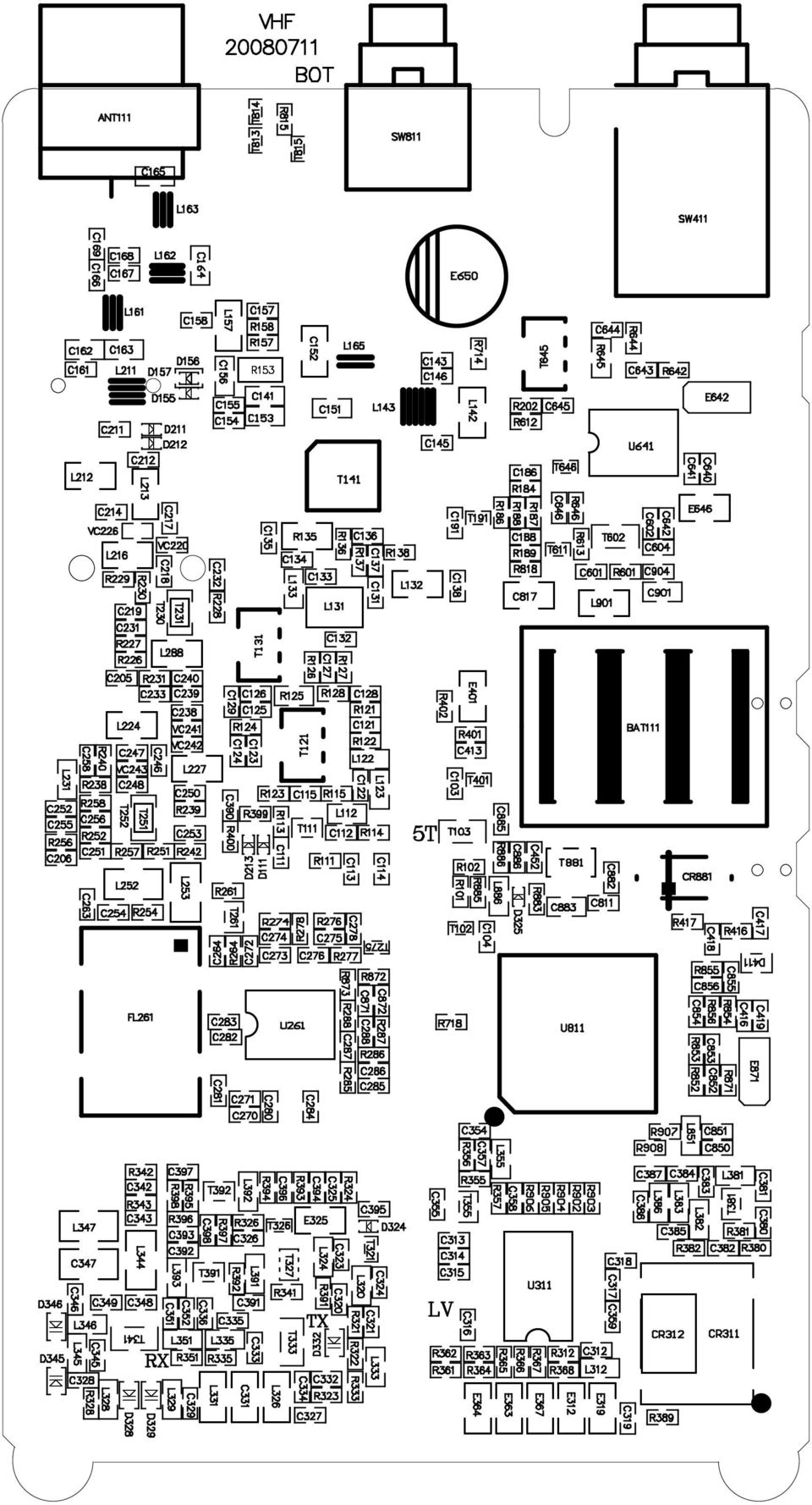
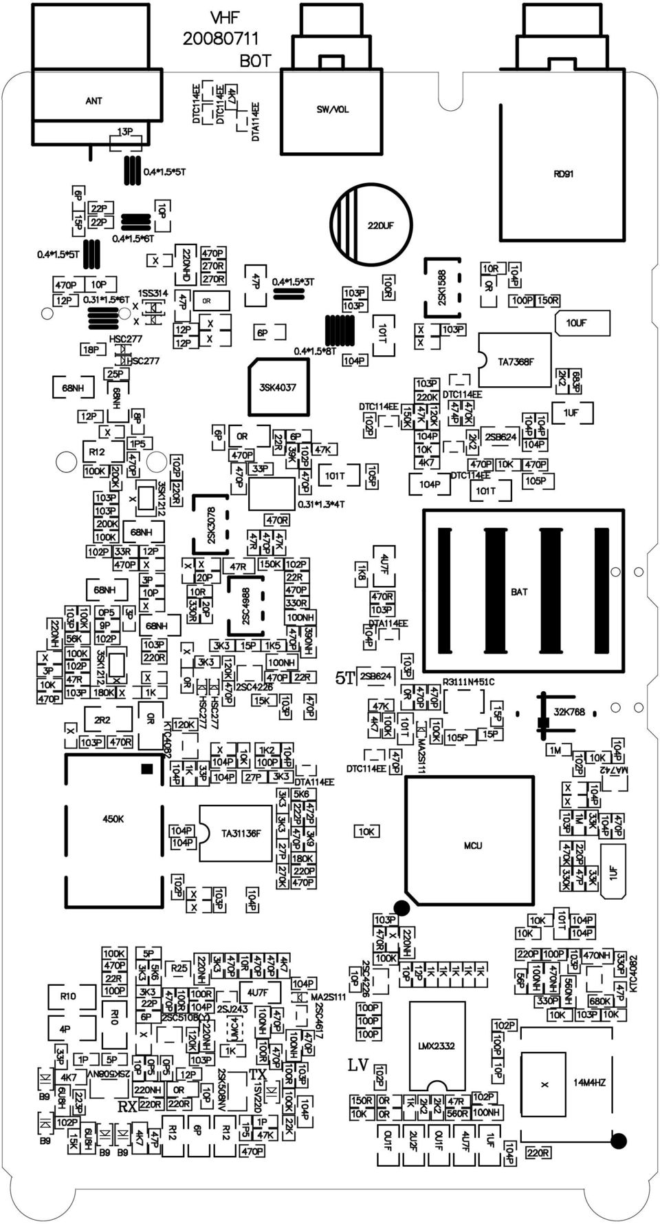
1 SERVICE MANUAL MJ- VHF FM TRANSCEIVERS

2 SPECIFICATIONS GENERAL Frequencyy Range Workingg Temperate --MHz -0 ~+ Operating Voltage DC.V Current Consumption.A(transmit W) Sensitivity Adjust Antenna impedance 0mV 0Ω TRANSMITTER Frequency Stability Output Power Maxx Frequency Deviation Audio Distortion Adjacent Channel Power Occupied Bandwidth RF Sensitivity : Audio Output ±ppm W(High),W(Low) KHz % -db KHz μv 0.W Audio Distortion 0% All stated specifications are subject to change without notice or obligation.
,W(Low) KHz % -db KHz μv 0.")
3 CIRCUIT DESCRIPTION. Frequency configuration The receiver utilizes double conversion. The first IF is.mhz and the second IF is 0kHz. The first local oscillator signal is supplied from the PLL circuit. The PLL circuit in the transmitter generates the ecessary frequencies. Fig. shows the frequencies.. Receiver The freauency configuration of the receiver is shown in Fig.. ) Front - end RF amplifier An incoming signal from the antenna is applied to an RF amplifier (T) after passing through a transmit/receive switch circuit (D,D,D) and a -pole LC filter(l,c).after the signal is amplified (T), the signal is filtered by a band pass filter (a -pole LC filter) (L0,C0,L,L) to eliminate unwanted signals before it is passed to the first mixer. The voltage of these diodes are controlled by to track the MPU(U) center frequency of the band pass filter. (See Fig. )
, the signal is filtered by a band pass filter (a -pole LC filter) (L0,C0,L,L) to eliminate unwanted signals before it is passed to the first mixer.")
4 ) First Mixer The signal from the RF amplifier is heterodyned with the first local oscillator signal from the PLL frequency synthesizer circuit at the first mixer (T) to create a.mhz first intermediate frequency (st IF) signal. The first IF signal is then fed through crystal filters (FL,FL) to further remove spurious signals. ) IF amplifier The first IF signal is amplified by T, and then enters U (FM processing IC). The signal is heterodyned again with a second local oscillator signal within U to create a 0kHz second IF signal. The second IF signal is then fed through a 0kHz ceramic filter (FL) to further eliminate unwanted signals before it is amplified and FM detected in FL0. ) AF amplifier The recovered AF signal obtained from U goes to the microprocessor(u). The processed AF signal passes through an AF volume control and is amplified to a sufficient level to drive a loud speaker by an AF power amplifier (U). ) Squelch Part of the AF signal from the IC enters the FM IC again,and the noise component is amplified and rectified by a filter and an amplifier to produce a DC voltage corresponding to the noise level. The DC signal from the FM IC goes to the analog port of the microprocessor (U). U determines whether to output sounds from the speaker by checking whether the input voltage is higher or lower than the preset value.to output sounds from the speaker, U sends a high signal to the AF Power Iines and turns U on through T,T. ) Receive signaling QT/DQT The output signal from FM IC (U) enters the microprocessor(u).u determines whether the QT or DQT matches the preset value, and controls the AF Power and the speaker output sounds according to the squelch results. PLL frequency synthesizer The PLL circuit generates the first local oscillator signal for reception and the RF signal for transmission. ) PLL The frequency step of the PLL circuit is and.khz and so on. A 9.MHz reference oscillator signal is divided at U by a fixed counter to produce the or.khz reference frequency. The voltage controlled oscillator (VCO) output signal is buffer amplified by T0, then divided in U by a programmable counter. The divided signal is compared in phase with the or.khz reference signal in the phase comparator in U. The output signal from the phase comparator is filtrered through a low-pass filter and passed to the VCO to control the oscillator frequency. ) VCO The operating frequency is generated by T0 in transmit mode and T in receive mode. The oscillator frequency is controlled by applying the VCO control voltage, obtained from the phase comparator, to the varactor diodes (D0 and D in transmit mode and D0 and D in receive mode). The TC/RC pin is set low in receive mode causing T off, and turn T on. The TC/RC pin is set hight in transmit mode causing T off,and T9,T9 on.

5 ) UNLOCK DETECTOR FB If a pulse signal appears at the LD pin of U, an unlock condition occurs, and the DC voltage obtained from D09, and C causes the voltage applied to the PLL-LD pin of the microprocessor to go low. When the microprocessor detects this condition, the transmitter is disabled, ignoring the push-totalk switch input signal. ( See Fig.). Transmitter )Microphone Amplifier The signal from the microphone passes through U.The signal passes through the Audio processor(u) for the maximum deviation adjustment,and goes to the VCO modulation input. )Drive and Final Amplifier The signal from the T/R switch(d and D) is amplified by the pre-drive(t.t0) and drive amplifier(t) to 0mW.The output of the drive amplifier is amplified by the RF power amplifier(t) to.0w(w when the power is low).the RF power amplifier consists of two MOS FET stages.the output of the RF power amplifier consists of two MOS FET stages.the output of the RF power amplifier is then passed through the harmonic filter (LPF) and antenna switch (D,D)and applied to the antenna terminal.. Power supply There are four V power supplies for the microprocessor: M,C,R,and T,M for microprocessor is always output while the power is on.m for microprocessor is always output while the power is on.m is always output,but turns off when the power is turned off to prevent malfunction of the microprocessor. C is a common V and is output when SAVE is not set to OFF. R is V for reception and output during reception. T is V for transmission and output during transmission..control Circuit The control circuit consists of a microprocessor (U) and its peripheral circuits.it controls the T-R unit.u mainly performs the following: () Switching between transmission and reception by the PTT signal input. () Reading system,group,frequency,and program data from the memory circuit. () Sending frequency program data to the PLL. () Controlling squelch on/off by the DC voltage from the squelch circuit. () Controlling the audio mute circuit by the decode data input. () Transmitting tone and encode data.
 for the maximum deviation adjustment,and goes to the VCO modulation input.")
6 )Memory Circuit Memory circuit consists of the CPU (U) and an EEPROM(U).An EEPROM has a capacity of K bits that contains the transceiver control program for the CPU and data such as Transceiver channels and operation features )Low Battery Warning The battery voltage is checked using by the microprocessor. () The red LED blinks when the battery voltage falls below.v. () A Warning tone generates when the red LED blinking. ( See Fig.)
 The red LED blinks when the battery vo")
7 ADJUSTMENT Required Test Equipment The following items are required to adjust radio parameters:. Regulated power supply Supply voltage: -V DC Current: A or more. Digital multimeter Voltage range: FS = Approx. 0V Current: 0A or more Input resistance: High impedance. Oscilloscope Measurable frequency: Audio frequency. Audio dummy load Impedance: ohm Dissipation: W or more Jack:.mm. SSG Output frequency: 00MHz or more Output level: -0dBu/0.uV -0dBu/V Modulation: FM. Spectrum Analyzer Measuring range: Up to GHz or more. Power meter Measurable frequency: Up to 00MHz Impedance: 0, unbalanced Measuring range: 0.W -0W. Audio volmeter Measurable frequency: Up to 00KHz Sensitivity: mv to 0V 9. Audio generator Output frequency: Hz to 0KHz

8 Output impedance: 00, unbalanced 0.Distortion meter/sinad meter Measurable frequency: khz Input level: Up to 0dB Distortion: % - 00%.Frequency counter Measurable frequency: Up to 00MHz Measurable stability: Approx. +/-0.ppm.Linear detector Measurable frequency: Up to 00MHz Characteristics: Flat CN: 0dB or more Note Standard modulation: khz +/-.khz/dev Reference sensitivity: db SINAD Specified audio output leve: 00mW at

9 00P 0P 0P 0P 0P 0P 0P 0P 0P P P P P P P P P 0P 0P 9P 0P 00K 0 0K 0K K 0KD 0K K K K K 00 Capacitance C9. C. C. C. C. C. C. C. C9. C0. C 00 Capacitance C. C0. C. C9. C0. C. C0. C90 C0. C. C0. C. C. C9. 00 Capacitance C9. C. C9. C. C. C. C. C. C9. C9 00 Capacitance C. C0. C. C. C. C. C0. C. C0. C. C 00 Capacitance C. C 00 Capacitance C 00 Capacitance C. C9 00 Capacitance C 00 Capacitance C. C. C 00 Capacitance C0. C. C9 00 Capacitance C. C 00 Capacitance C. C. C 00 Capacitance C 00 Capacitance C. C9. C. C0. C. C0. C. C. C. C. C. C9 00 Capacitance C. C. C 00 Capacitance C0. C 00 Capacitance C 00 Capacitance C 00 Capacitance C 00 Capacitance C 00 Capacitance C 00 Capacitance C 00 Resistor R 00 Resistor R0. R. R0. R. R 00 Resistor R. R0. R. R. R. R 00 Resistor R. R. R. R9. R. R. R. R. R0. R. R909. R90 00 Resistor R0 00 Resistor R. R9 00 Resistor R 00 Resistor R9. R9. R9. R9. R9. R9 00 Resistor R 00 Resistor R0 00 Resistor R. R. R9. R. R9. R900. R90 00 Resistor R. R 00 Resistor R

10 M M 00K 0K K K K K 0K K K 90K 9K K K9 K K K K 0K K K 9 K UF UF UF 0UF 0UF 0T GREEN RED SS DAN SK DTAEE DTCEE MRF9 SB C CHORD LM 00 Resistor R. R. R 00 Resistor R. R 00 Resistor R 00 Resistor R9 00 Resistor R0. R 00 Resistor R 00 Resistor R 00 Resistor R. R 00 Resistor R. R. R9. R 00 Resistor R. R. R. R. R. R 00 Resistor R. R 00 Resistor R 00 Resistor R. R 00 Resistor R. R. R 00 Resistor R 00 Resistor R 00 Resistor R0. R9. R. R. R 00 Resistor R0. R. R. R. R. R. R 00 Resistor R 00 Resistor R. R 00 Resistor R 00 Resistor R0 00 Resistor R 00 Resistor R. R 00 Resistor R 0 Resistor R. R. R 0 Resistor L 00 Pol-Cap E 00 Pol-Cap E 00 Pol-Cap E. E. E. C9 A Pol-Cap E. E9 B Pol-Cap E9 00 Ind L0. L 00 G-LED D 00 R-LED D USM Diode D USM Diode D ESM Transistor T. T ESM Transistor T0 ESM Transistor T USM Transistor T TSM Transistor T0 SO IC U SO IC U SO IC U

11 LM LM90V F A MHZ 0K MONI PTT SCR JP Bottom Comment 0P 00P 0P 0P 0P 0P 0P P P P P P 0P 0P P P P P P 0P P P SO IC U SSOP IC U SSOP IC U SOT9 IC U9 F-CS0 Oscillator CR Var-Res RV. RV Button SW Button SW Button SW Connectors JP Footprint Name Designators Quantity 00 Capacitance C. C. C C. C. C. C. C. C. Capacitance C. C C. C. C9. C0. C. C. Capacitance C. C. C. C. C. C. C C. C. C. C. C9. C. Capacitance C0. C. C. C. C0. C. C. C. C. C9. C. C. 0 C. C C0. C. C. C. C. C. Capacitance C. C. C. C. C9. C. C9. C. C. C0. C0. C. 00 C0. C. C. R 00 Capacitance C 00 Capacitance C. C. C. C9. R. VC C. C. C. C. C0. C. 00 Capacitance C 00 Capacitance C. C. C. C 00 Capacitance C 00 Capacitance C. C9 00 Capacitance C. VC0 00 Capacitance C. C 00 Capacitance C. C. C 00 Capacitance C 00 Capacitance C 00 Capacitance C. C. C9 00 Capacitance C 00 Capacitance C. C 00 Capacitance C. C 00 Capacitance C. C. C 00 Capacitance C. C. C

12 C0. C. C. C. C. C. C. C. C. C. C0. C. 00 Capacitance C. C. C. C0. C. C. 9 C. C. C. C9. C9. C9. C9. C. C0. C. C90 P 00 Capacitance C P 00 Capacitance C P 00 Capacitance C9. C0. C P 00 Capacitance C P 00 Capacitance C. C9 P 00 Capacitance C0 P 00 Capacitance C. C. C9. C9 P 00 Capacitance C 9P 00 Capacitance VC 0P 00 Capacitance L 0P 00 Capacitance C. C90 0P 00 Capacitance C. C P 00 Capacitance C 00 Capacitance C. L P 00 Capacitance C P 00 Capacitance C 0P 00 Capacitance C P 00 Capacitance C P 00 Capacitance C P 00 Capacitance C 00 Resistor R. R. R00. R 00K 00 Resistor R. R9. R0. R. R. R. R. R. R Resistor R. R. R9. R9. R 0K 00 Resistor R9. R. R. R. R0. R. R. R0. R. R90. R90 00 Resistor R. R9. C 0K 00 Resistor R. R. R. R9 0K 00 Resistor R. R 00 Resistor R. R K 00 Resistor R. R 0K 00 Resistor R. R K 00 Resistor R. R. R. R. R90. R90. R90. R90. R90 9 K 00 Resistor R K 00 Resistor R K 00 Resistor R0 M 00 Resistor R. R 00K 00 Resistor R. R0

13 0K K R 0K K 0K K R 9K K K9 0K K R K K K 0K R K 0UF UF UF UF UF 0UF 00NH 0NH 90NH 0NH 0NH 0NHD UH 0T 0T NH R0 R 00 Resistor R 00 Resistor R. R9. R. R. R9 00 Resistor R 00 Resistor R. R. R. R 00 Resistor R 00 Resistor R. R 00 Resistor R. R. R. C 00 Resistor R 00 Resistor R. C 00 Resistor R. R 00 Resistor R 00 Resistor R 00 Resistor R. R. R. R9. R9. R9. R99. R 00 Resistor R 00 Resistor R. R 00 Resistor R. R. R0. C 00 Resistor R0. R. R. R. R 00 Resistor R. R. R 00 Resistor R0. R. R. R 00 Resistor R 00 Resistor R 00 Resistor R9. R 00 Resistor R 00 Resistor L. R 00 Resistor R 00 Resistor L9. L 00 Resistor R. R. L 00 Pol-Cap E. E 00 Pol-Cap E9. E 00 Pol-Cap E 00 Pol-Cap E. E. E0 A Pol-Cap E A Pol-Cap E 00 Ind L. L. L. L0. L. L 00 Ind L. L. L. L9. L9 00 Ind L 00 Ind L. L 00 Ind L 00 Ind L 00 Ind L. L 00 Ind L. L 00 Ind L. L. L90 00 Ind L. L. L. L. L 00 Ind L. L 00 Ind L. L. L

14 R T T T T T T HSC MAS SS SV0 B9 MA SC SJ DTAEE DTCEE SC SC0(Y) KTC0 R UMC SB SK0NV RN SC9 SK SK0 SK SK0 MCU TAF TAF LM MHZ K 0K BAT 00 Ind L 0.*.mm Coil-Ind L 0.*.mm Coil-Ind L 0.*.mm Coil-Ind L. L 0.*.mm Coil-Ind L 0.*.mm Coil-Ind L 0.*.mm Coil-Ind L ESC Diode D. D. D. D ESC Diode D. D USC Diode D USC Diode D USC Diode D. D9. D. D USM Diode D ESM Transistor T ESM Transistor T ESM Transistor T. T0. T ESM Transistor T0. T9. T. T. T. T USM Transistor T. T USM Transistor T9 USM Transistor T. T USM Transistor T9 USV Transistor T TSM Transistor T0. T0 TSM Transistor T. T TSV Transistor T SOT9 Transistor T SOT9 Transistor T SOT9 Transistor T SOT Transistor T. T HWSON- Transistor T QFP IC U SSOP0 IC U SSOP IC U SSOP0 IC U Oscillator CR Oscillator CR Filters FL Battery BAT

15 EPLODED VIEW A 0 B A B B B C C C C C C C C

16

17
18

19
20 K K K 00P K 0P0P LCD C0 C 00P /RD /WR 00P DATA VSS OSCO OSCI VLCD VDD C C HVU ANT P P P P P P P 0P 0.*.*T T P 0NH( 叠 层 ) UH P 9 0.*.*T 0.*.*T 0.*.*T HSC HSC P NH( 绕 线 ) NH VHF P R( 绕 线 ) P 00K R NH( 绕 线 ) R 0P P SK(YK-) P NH( 绕 线 ) 0P 9P P NH( 绕 线 ) 9P 0P 0K P 0nH( 叠 层 ) TP 0P 0 R( 绕 线 ) SK(YK-) P R( 绕 线 ) 0P 0P M0 9P M0 0P 0 0K R 0 K SC(QY) 0UF P SC(QY) 0P 0K TAFN 0P P 00P 0P 0K K 0C DTAEE 0P P TP 0NH R 0P P 0 0NH 0K 0P P 0K 0P 0 0K K9 0K P K TP K K K P P 0P 0μF 0K SQ P N/W RI VCC SW-VOL P 0P VCC 0P 0P K SB 0UF 9 0K 0K 0P 0 9 TAF K DTCEE() 00P P SK(NG) 0UF 0P DTCEE() BAT VCC BATT 0UF 0P 0P K SP JACK K SP 00P C P P P P M P K N.U. 0P K 0P 0K P K 0P K 0P 00K 0P 00K K K 9P M FUSE PB 00NH( 磁 珠 ) UF SR-00 0P 0P P P P P P VCC P C 0T( 磁 珠 ) R K SC(BR) UF DC SW MAS UMC 00K K C RVCO SJ HSC HSC K TVCO K K P 0nH( 叠 层 ) R 0 C K K P 0 P R 0nH( 叠 层 ) R 0 0K 00P 0P 0nH( 叠 层 ) 0P 0P 0P 0P R0( 绕 线 ) P K 0P K R( 绕 线 ) P SV0 0P P R_VCO P K P R0( 绕 线 ) T_VCO P R( 绕 线 ) 0P P 00K 0P B9 B9 B9 B9 0 μh( 磁 珠 ) 0P K μh( 磁 珠 ) 00P 00nH C 0K K K μf 0μF K 0μF TP M 0P P 0P K 0K 0P AUR F/M 00K 00K 00K K 0P 0P 0K 00K 0P K K 0P 0P 0P 0K 0P 0 9 P SK(B) P TONE 0P 0P K V 90K CHORD K 00K DATA CLK R-ANI 0P VR 00K 0P 0P K9 0K LM K K 0K 0K LM K 0P 0K VR 0K P K 0P AUR 0.*.*T P K(B) 0K(B) 0K(B) VCC 0T( 磁 珠 ) 0T 0K(B) RQA000 0K(B) LM90() VCC P K 0K(B) 0P 0P NH( 叠 层 ) R 00P T DTCEE 9K 0K 0P P K 0K 0P 0P K P 0P SK0(UW) M 0K 0UF 0P R0J( 绕 线 ) 0T( 磁 珠 ) R K 0P LM90() 0P 0K DTCEE K R 0K 0P 0P 0P SC(RF) P APC PB PB PB 90NH( 磁 珠 ) V T 00NH( 叠 层 ) R 0P K9 K P 9 /CS 0 /IRQ S0 R 00NH( 叠 层 ) SC(R) S0 BI S K 0K S /BI S S LCD Driver C0 C C 0P C C 0NH( 叠 层 ) 00K S 0P S S S0 S S9 0P 9 S9 R 0 S0 U S P P S S S S S S S S K 0 CLK PB P0 K DTCEE() OUT DATA PB K IN STB P9 LED 00P Fin 三 色 背 光 灯 PC0 GND LM 00P Fin GDN 00P LED BACK_LIGHT DTCEE() CP CP 0P VP VP 9 00P VCC VCC 0 N N LED(R) VCC 0P LED LED VCC R 00nH( 叠 层 ) DTCEE() UF LED LED LED(G) DTCEE() 0P 0P C 键 盘 灯 LED FOUT VCC 0P PC 9M 0P LED BACK_LIGHT GND VT 0K P 9K K K QT/DQT P P P P P P0 PC0 PC PC TONE UF K K K PC MICO MICI VSS V 0P 0P 9 0 VDD K P P P P P 0T T-ANI P P L L C TONE K K K P 0 0P O U T P 0P 9 P P MCU IN TP K K P P 9 P P A V S S AUR 0K /R E S E T P P A V D D 0 M P P K C 0P R 00K R 00K D N.U. MAS 0 9 0T P9 P9 P9 P9 P9 P9 P9 P90 PB PB PB RI 0P RO K 0P 0K V 0P SC(BR) RNC-TR-FA out Gnd in T C K K K K P90 P9 P9 P9 P9 0K V T M 0P V 0P K P C 0P K K K P K PB SC(BR) 0K N N N N N 0K 0K P M 0P ALARM MONI 9 D V T 0P K P DTCEE() K O < 0P K K 0 N/W * 0 # K 0P T () K > A B C 0K K 0P T UF VCC K P 0K 0K 0K P T 0UF 0P 0P SB(BV) V 0P VCC MA 0P () K 0P Vin μf P 0K SC A GND K 0P 0P 0P Vout R 0UF P K SS(N9) V P K μf V 0K 0P K V DTAYE 00K SB(BV) 0P 0P UF VO K 0P SC(L) V K 0T( 磁 珠 ) 0P 0UF V K K K K C 0UF V K 00K 0P SB(BV) 0P 0 0P 0P K 0 0 V MIC MIC JACK 0 PTT K 0K V SW-CH 0P P P P P P9 P9 P

Circuit Description. The signal from the antenna is passed through atransmission/reception selector circuit and is
 Circuit Description.RECEIVER The signal from the antenna is passed through atransmission/reception selector circuit and is amplified by T7. The signalafter amplified enter to 86 for processing thenoutput
MAINTENANCE & ADJUSTMENT
 MAINTENANCE & ADJUSTMENT Circuit Theory The concept of PLL system frequency synthesization is not of recent development, however, it has not been a long age since the digital theory has been couplet with
VHF COMMUNICATION TRANSCEIVER
 ATR-500 VHF COMMUNICATION TRANSCEIVER ON OFF OPERATION MANUAL Manual Number 01.125.010.08 REVISION 1.3, Jan 20. 2005 from S/N 00301 04 Contents 1 SECTION 1 GENERAL INFORMATION...3 1.1 INTRODUCTION...3
Kenwood introduces. new HF/50MHz All-Mode Transceiver
 New Product Release Information Oct 2014 TS-590SG HF/ 50MHz All-Mode TRANSCEIVER_ Kenwood introduces Updated to new G version new HF/50MHz All-Mode Transceiver Four years ago we launched our best-selling
LM 358 Op Amp. If you have small signals and need a more useful reading we could amplify it using the op amp, this is commonly used in sensors.
 LM 358 Op Amp S k i l l L e v e l : I n t e r m e d i a t e OVERVIEW The LM 358 is a duel single supply operational amplifier. As it is a single supply it eliminates the need for a duel power supply, thus
Features. Applications. Transmitter. Receiver. General Description MINIATURE MODULE. QM MODULATION OPTIMAL RANGE 1000m
 Features MINIATURE MODULE QM MODULATION OPTIMAL RANGE 1000m 433.05 434.79 ISM BAND 34 CHANNELS AVAILABLE SINGLE SUPPLY VOLTAGE Applications IN VEHICLE TELEMETRY SYSTEMS WIRELESS NETWORKING DOMESTIC AND
ZLPLL Local Oscillator
 ZLPLL Local Oscillator Wayne Knowles, ZL2BKC [email protected] Contents 1 Introduction... 3 2 Specifications... 3 3 Performance... 4 3.1 Phase Noise... 4 3.2 Output Level... 4 3.3 Harmonic Level...
Amplifier for Small Magnetic and Electric Wideband Receiving Antennas (model AAA-1B)
") Amplifier for Small Magnetic and Electric Wideband Receiving Antennas (model AAA-1B) 1. Description and Specifications Contents 1.1 Description 1.2 1.2 Specifications 1.3 1.3 Tested parameters in production
Amplifier for Small Magnetic and Electric Wideband Receiving Antennas (model AAA-1B) 1. Description and Specifications Contents 1.1 Description 1.2 1.2 Specifications 1.3 1.3 Tested parameters in production
ic- 2730a (USA, EXP) ic- 2730e (Europe)
 ic- 2730e (Europe)") November 2014 VHF/UHF DUAL BAND TRANSCEIVERS ic- 2730a (USA, EXP) ic- 2730e (Europe) Icom proudly announces the debut of the new VHF/UHF dual band transceiver, IC-2730A/2730E. It is the successor of the
November 2014 VHF/UHF DUAL BAND TRANSCEIVERS ic- 2730a (USA, EXP) ic- 2730e (Europe) Icom proudly announces the debut of the new VHF/UHF dual band transceiver, IC-2730A/2730E. It is the successor of the
A CW QRP Transceiver for 20 m band. How it works I'll describe individually the three boards and the relative tuning devices.
 A CW QRP Transceiver for 20 m band The little QRP presented in this article may be built in a gradual manner, in fact it is divided in two main modules (plus VFO), you may also complete only a single part
SR450 RECEIVER OPERATING INSTRUCTIONS 1892 1128
 SR450 RECEIVER OPERATING INSTRUCTIONS 1892 1128 These operating instructions are intended to provide the user with sufficient information to install and operate the module correctly. The Wood & Douglas
Turbo X. www.smartwireless.co.uk. 594 channel UHF true diversity
 Turbo X 594 channel UHF true diversity The new Turbo X series from Smart Wireless is the culmination of two years of research and development into advanced wireless technology. Using sophisticated RF design
Product Information S N O. Portable VIP protection CCTV & Alarm System 2
 Product Information S N O Portable VIP protection CCTV & Alarm System 2 G O V E R N M E N T A L S E C U R I T Y S O L U T I VIP KIT Rapid Deployment VIP Protection Kit The VIP KIT has been designed to
TOTALLY SOLID STATE NON-DIRECTIONAL RADIO BEACONS 190-535 khz
 TOTALLY SOLID STATE NON-DIRECTIONAL RADIO S 190-535 khz This family of radio transmitters has been developed as extremely efficient, highly reliable Non Directional Beacons. ND2000A/4000A» MODULAR CONSTRUCTION»
Alpha 10 SERVICE MANUAL. Downloaded from www.cbradio.nl. MAX 10 Meter Amateur Transceiver AM/FM/CW/SSB 6 BAND PROGRAMMABLE MODEL AM-1000.
 Alpha 10 MAX 10 Meter Amateur Transceiver MODEL AM-1000 AM/FM/CW/SSB 6 BAND PROGRAMMABLE SERVICE MANUAL Downloaded from www.cbradio.nl Cover Page LOUDER TALKBACK MOD Alpha 10 Max - Model AM-1000 4.7K Resistor
Enhanced In-house Voice Communication over Power- Line Network
 International Journal of Scientific and Research Publications, Volume 3, Issue 7, July 2013 1 Enhanced In-house Voice Communication over Power- Line Network Asif Hassan Senior Lecturer, Dept. of ECE, HMSIT,
Modification Details.
 Front end receiver modification for DRM: AKD Target Communications receiver. Model HF3. Summary. The receiver was modified and capable of receiving DRM, but performance was limited by the phase noise from
How To Use A Sound Card With A Subsonic Sound Card
 !"## $#!%!"# &"#' ( "#' )*! #+ #,# "##!$ -+./0 1" 1! 2"# # -&1!"#" (2345-&1 #$6.7 -&89$## ' 6! #* #!"#" +" 1##6$ "#+# #-& :1# # $ #$#;1)+#1#+
DATA SHEET. TDA8560Q 2 40 W/2 Ω stereo BTL car radio power amplifier with diagnostic facility INTEGRATED CIRCUITS. 1996 Jan 08
 INTEGRATED CIRCUITS DATA SHEET power amplifier with diagnostic facility Supersedes data of March 1994 File under Integrated Circuits, IC01 1996 Jan 08 FEATURES Requires very few external components High
www.fmtalkinghouse.com
 www.fmtalkinghouse.com 24x7 FM Announcement System (Talking Sign) 2009 FM TALKING HOUSE All rights reserved Talking Sign 24x7 FM Announcement System Description: The 24x7 FM Announcement System or Talking
THE R551N RECEIVER FAQ FAULT FINDING THE REDIFON COMMUNICATIONS RECEIVER R551N. Date: October 10th 1995 by: Jan Verduyn G5BBL
 THE R551N RECEIVER FAQ FAULT FINDING THE REDIFON COMMUNICATIONS RECEIVER R551N Introduction: Date: October 10th 1995 by: Jan Verduyn G5BBL Recently a number of Redifon R551N receivers have appeared on
How To Sell A Talan
 The TALAN represents state-of-the-art capability to rapidly and reliably detect and locate illicit tampering and security vulnerabilities on both digital and analog telephone systems. Marketing Characteristics
POCKET SCOPE 2. The idea 2. Design criteria 3
 POCKET SCOPE 2 The idea 2 Design criteria 3 Microcontroller requirements 3 The microcontroller must have speed. 3 The microcontroller must have RAM. 3 The microcontroller must have secure Flash. 3 The
Single Transistor FM Transmitter Design
 Single Transistor FM Transmitter Design In telecommunications, frequency modulation (FM) conveys information over a carrier wave by varying its frequency. FM is commonly used at VHF radio frequencies for
VJ 6040 Mobile Digital TV UHF Antenna Evaluation Board
 VISHAY VITRAMON Multilayer Chip Capacitors Application Note GENERAL is a multilayer ceramic chip antenna designed for receiving mobile digital TV transmissions in the UHF band. The target application for
Kit 106. 50 Watt Audio Amplifier
 Kit 106 50 Watt Audio Amplifier T his kit is based on an amazing IC amplifier module from ST Electronics, the TDA7294 It is intended for use as a high quality audio class AB amplifier in hi-fi applications
unit:mm 3022A-DIP12F 0.5 0.81 2.54
 Ordering number:enn1718b Monolithic Linear IC LA4550 2-Channel AF Power Amplifier for Radio, Tape Recorder Use Features Low quiescent current. On-chip 2 channels permitting use in stereo and bridge amplifier
INTEGRATED CIRCUITS DATA SHEET. TDA7000 FM radio circuit. Product specification File under Integrated Circuits, IC01
 INTEGRATED CIRCUITS DATA SHEET File under Integrated Circuits, IC01 May 1992 GENERAL DESCRIPTION The is a monolithic integrated circuit for mono FM portable radios, where a minimum on peripheral components
Baseband delay line QUICK REFERENCE DATA
 FEATURES Two comb filters, using the switched-capacitor technique, for one line delay time (64 µs) Adjustment-free application No crosstalk between SECAM colour carriers (diaphoty) Handles negative or
PolyBot Board. User's Guide V1.11 9/20/08
 PolyBot Board User's Guide V1.11 9/20/08 PolyBot Board v1.1 16 pin LCD connector 4-pin SPI port (can be used as digital I/O) 10 Analog inputs +5V GND GND JP_PWR 3-pin logic power jumper (short top 2 pins
Experiment # (4) AM Demodulator
 AM Demodulator") Islamic University of Gaza Faculty of Engineering Electrical Department Experiment # (4) AM Demodulator Communications Engineering I (Lab.) Prepared by: Eng. Omar A. Qarmout Eng. Mohammed K. Abu Foul Experiment
Islamic University of Gaza Faculty of Engineering Electrical Department Experiment # (4) AM Demodulator Communications Engineering I (Lab.) Prepared by: Eng. Omar A. Qarmout Eng. Mohammed K. Abu Foul Experiment
Content. Maintenance. Features ENGLISH. 1 transceiver 1 antenna 1 battery pack 1 belt clip 1 fast desktop charger User manual
 Contents Maintenance... 2 Features... 2 Main indicators/controls... 3 LCD display... 5 Basic operations... 6 Advanced operations... 15 Menu operations Self-Programming mode... 17 Self-programming chart...
Part Number Description Packages available
 Features 3 digital I/O Serial Data output Connects directly to RF Modules Easy Enc / Dec Pairing Function Minimal External Components Required Performs all encoding/decoding of data for Reliable Operation.
VCO Phase noise. Characterizing Phase Noise
 VCO Phase noise Characterizing Phase Noise The term phase noise is widely used for describing short term random frequency fluctuations of a signal. Frequency stability is a measure of the degree to which
DRM compatible RF Tuner Unit DRT1
 FEATURES DRM compatible RF Tuner Unit DRT1 High- Performance RF Tuner Frequency Range: 10 KHz to 30 MHz Input ICP3: +13,5dBm, typ. Noise Figure @ full gain: 14dB, typ. Receiver Factor: -0,5dB, typ. Input
Youkits TJ2B 2016 SSB CW HF TRANSCEIVER OPERATION GUIDE
 Youkits TJ2B 2016 SSB CW HF TRANSCEIVER OPERATION GUIDE TJ2B is a high-performance QRP portable multi-band SSB/CW transceiver, used with DDS as LO, offering wide frequency coverage and fine tuning rate.
Series AMLDL-Z Up to 1000mA LED Driver
 FEATURES: Click on Series name for product info on aimtec.com Series Up to ma LED Driver Models Single output Model Input Voltage (V) Step Down DC/DC LED driver Operating Temperature range 4ºC to 85ºC
SA605 High performance low power mixer FM IF system
 RF COMMUNICATIONS PRODUCTS High performance low power mixer FM IF system Replaces data of November 3, 1992 RF Communications Handbook 1997 Nov 07 Philips Semiconductors DESCRIPTION The is a high performance
Wireless. with Personal Mix Control and EP3 Dynamic Earphones
 Wireless In-Ear Monitor Systems with Personal Mix Control and EP3 Dynamic Earphones Why In-Ear Monitors? Clarity is first among the many reasons to make the switch from traditional floor monitors to wireless
Homebuilt HF Radios for Use Underground Paul R. Jorgenson KE7HR
 Homebuilt HF Radios for Use Underground Paul R. Jorgenson KE7HR With the good success in using Amateur Band HF radio for underground communications, I started looking for cheaper alternatives to the $500+
Application Note SAW-Components
 Application Note SAW-Components Principles of SAWR-stabilized oscillators and transmitters. App: Note #1 This application note describes the physical principle of SAW-stabilized oscillator. Oscillator
LOW POWER NARROWBAND FM IF
 Order this document by MC336B/D The MC336B includes an Oscillator, Mixer, Limiting Amplifier, Quadrature Discriminator, Active Filter, Squelch, Scan Control and Mute Switch. This device is designed for
Absolute maximum. User Manual
 RTX-MID-3V/ is an RF digital data transceiver working on the ISM free-license band of 433.92 MHz, in half-duplex way, ASK modulated and fast switch time TX RX and RX TX. It s ideal for low cost solutions,
VMR6512 Hi-Fi Audio FM Transmitter Module
 General Description VMR6512 is a highly integrated FM audio signal transmitter module. It integrates advanced digital signal processor (DSP), frequency synthesizer RF power amplifier and matching network.
PT2508/3508 VHF/UHF HANDHELD TRANSCEIVER INSTRUCTION MANUAL
 PT2508/3508 VHF/UHF HANDHELD TRANSCEIVER INSTRUCTION MANUAL 0681 0681 TO THE USER THANK YOU! We are grateful you have chosen application. for your land mobile We believe this easy to use transceiver will
AppNote 404 EM MICROELECTRONIC - MARIN SA. EM4095 Application Note RFID. Title: Product Family: TABLE OF CONTENT. Application Note 404
 EM MICROELECTRONIC - MARIN SA AppNote 0 Title: Product Family: Application Note 0 EM095 Application Note RFID Part Number: EM095 Keywords: RFID Transceiver, Reader Chip, EM095 Date: 5 September 00 TABLE
Spread Spectrum Clock Generator
 Spread Spectrum Clock Generator DESCRIPTION is a clock generator for EMI (Electro Magnetic Interference) reduction. The peak of unnecessary (EMI) can be attenuated by making the oscillation frequency slightly
GSM Interfacing Board
 Campus Component Pvt. Ltd. DISCLAIMER Information furnished is believed to be accurate and reliable at the time of publication. However, Campus Component Pvt. Ltd. assumes no responsibility arising from
Tire pressure monitoring
 Application Note AN601 Tire pressure monitoring 1 Purpose This document is intended to give hints on how to use the Intersema pressure sensors in a low cost tire pressure monitoring system (TPMS). 2 Introduction
Lecture 1: Communication Circuits
 EECS 142 Lecture 1: Communication Circuits Prof. Ali M. Niknejad University of California, Berkeley Copyright c 2005 by Ali M. Niknejad A. M. Niknejad University of California, Berkeley EECS 142 Lecture
Rayson. Bluetooth Module
 Rayson Class2 BC04-ext Module Features Bluetooth Module BTM-182 Outline Class2 module with printed pcb antenna Bluetooth standard Ver. 2.1 + EDR compliant. Low current consumption : Hold,Sniff,Park,Deep
DESIGN AND IMPLMENTATION OF INTELLIGENT MOBILE PHONE DETECTOR
 DESIGN AND IMPLMENTATION OF INTELLIGENT MOBILE PHONE DETECTOR Christian C. Mbaocha Department of Electrical/Electronic Engineering, Federal University of Technology, NIGERIA. [email protected] ABSTRACT
Optimizing VCO PLL Evaluations & PLL Synthesizer Designs
 Optimizing VCO PLL Evaluations & PLL Synthesizer Designs Today s mobile communications systems demand higher communication quality, higher data rates, higher operation, and more channels per unit bandwidth.
Wireless Audio Link IC
 BH7F Wireless Audio Link IC BH7F The BH7F is a FM stereo transmitter IC that transmits simple configuration. The IC consists of a stereo modulator for generating stereo composite signals and a FM transmitter
The basic set up for your K2 to run PSK31 By Glenn Maclean WA7SPY
 The basic set up for your K2 to run PSK31 By Glenn Maclean WA7SPY I am by no means an expert on PSK31. This article is intended to help someone get on PSK31 with a K2. These are the things I did to get
FM TRANSMITTER & RECEIVER HYBRID MODULES. FM-RTFQ SERIES FM-RRFQ SERIES. Transmitter. Receiver. Applications
 FM Radio Transmitter & Receivers Available as or or 868MHz Transmit Range up to 20m Miniature Packages Data Rate up to 9.6Kbps No Adjustable Components Very Stable Operating Frequency Operates from 20
DATA SHEET. TDA1518BQ 24 W BTL or 2 x 12 watt stereo car radio power amplifier INTEGRATED CIRCUITS
 INTEGRATED CIRCUITS DATA SHEET File under Integrated Circuits, IC01 July 1994 GENERAL DESCRIPTION The is an integrated class-b output amplifier in a 13-lead single-in-line (SIL) plastic power package.
HD61202U. (Dot Matrix Liquid Crystal GraphicDisplay Column Driver)
") HD622U (Dot Matrix Liquid Crystal GraphicDisplay Column Driver) Description HD622U is a column (segment) driver for dot matrix liquid crystal graphic display systems. It stores the display data transferred
HD622U (Dot Matrix Liquid Crystal GraphicDisplay Column Driver) Description HD622U is a column (segment) driver for dot matrix liquid crystal graphic display systems. It stores the display data transferred
TDA2040. 20W Hi-Fi AUDIO POWER AMPLIFIER
 20W Hi-Fi AUDIO POWER AMPLIFIER DESCRIPTION The TDA2040 is a monolithic integrated circuit in Pentawatt package, intended for use as an audio class AB amplifier. Typically it provides 22W output power
DDS VFO CONSTRUCTION MANUAL. DDS VFO Construction Manual Issue 1 Page 1
 DDS VFO CONSTRUCTION MANUAL DDS VFO Construction Manual Issue 1 Page 1 Important Please read before starting assembly STATIC PRECAUTION The DDS VFO kit contains the following components which can be damaged
PLL Frequency Synthesizer Evaluation Kit. PE3293-EK User s Manual
 PLL Frequency Synthesizer Evaluation Kit PE3293-EK User s Manual 6175 NANCY RIDGE DRIVE, SAN DIEGO, CA 92121 (858) 455-0660, FAX (858) 455-0770 http://www.peregrine-semi.com 1 Table of Contents FCC Labeling
The new Velleman Projects catalogue is now available. Download your copy here: www.vellemanprojects.eu
 The new Velleman Projects catalogue is now available. Download your copy here: www.vellemanprojects.eu Modifications and typographical errors reserved - Velleman nv. H8098 IP 2 (rev.1.0) Velleman NV, Legen
APPLICATION NOTE AP050830
 APPLICATION NOTE AP050830 Selection and use of Ultrasonic Ceramic Transducers Pro-Wave Electronics Corp. E-mail: [email protected] URL: http://www.prowave.com.tw The purpose of this application note
OPTIMA MK2 OWNERS MANUAL & USER GUIDE. Downloaded from www.cbradio.nl. 24.500 29.999 Mhz 50W All Mode HF Mobile Transceiver
 OPTIMA MK2 OWNERS MANUAL & USER GUIDE Downloaded from www.cbradio.nl 24.500 29.999 Mhz 50W All Mode HF Mobile Transceiver (February 2012 production) REV 1.61 Copyright January 2012 by YeticomNZ. All rights
PSM 900 and PSM 1000 Personal Monitor Systems TWO SYSTEMS. INFINITE POSSIBILITIES.
 PSM 900 and PSM 1000 Personal Monitor Systems TWO SYSTEMS. INFINITE POSSIBILITIES. PSM 900 AND PSM 1000 PERSONAL MONITOR SYSTEMS. ONLY FROM SHURE. PSM 900 PSM 1000 PSM 900 and PSM 1000 Personal Monitor
A PIC16F628 controlled FLL (Frequency Locked Loop) VFO for HF
 VFO for HF") Abstract A PI6F628 controlled FLL (Frequency Locked Loop) VFO for HF It is described a device which joins in a single microprocessor a digital programmable frequency meter and a control logic capable to
Abstract A PI6F628 controlled FLL (Frequency Locked Loop) VFO for HF It is described a device which joins in a single microprocessor a digital programmable frequency meter and a control logic capable to
Design and Certification of ASH Radio Systems for Japan
 Design and Certification of ASH Radio Systems for Japan RFM s second-generation ASH radio hybrids are being used in a wide variety of applications in Japan, operating under the Japanese BIJAKU radio regulations.
Hear The Future...Now! SIEM-2T/SIEM-2R
 Hear The Future...Now! SIEM-2T/SIEM-2R UHF PLL Mono In Ear Monitoring System 856 59508-03 ATTENTION Please pay high attention to the following information. The guideline published by Occupational Safety
AN1991. Audio decibel level detector with meter driver
 Rev. 2.1 20 March 2015 Application note Document information Info Keywords Abstract Content SA604A, LM358, RSSI, cellular radio The SA604A can provide a logarithmic response proportional to the input signal
Lab Experiment 1: The LPC 2148 Education Board
 Lab Experiment 1: The LPC 2148 Education Board 1 Introduction The aim of this course ECE 425L is to help you understand and utilize the functionalities of ARM7TDMI LPC2148 microcontroller. To do that,
THE BASICS OF PLL FREQUENCY SYNTHESIS
 Supplementary Reading for 27 - Oscillators Ron Bertrand VK2DQ http://www.radioelectronicschool.com THE BASICS OF PLL FREQUENCY SYNTHESIS The phase locked loop (PLL) method of frequency synthesis is now
Introduction to Receivers
 Introduction to Receivers Purpose: translate RF signals to baseband Shift frequency Amplify Filter Demodulate Why is this a challenge? Interference (selectivity, images and distortion) Large dynamic range
Operation Manual for Users
 Operation Manual for Users Model No.: FLTAMFMRCD!!!!!!!!!! ATTENTION!!!!!!!!!! THE RESET BUTTON MUST BE PRESSED TO ENSURE PROPER OPERATION. SEE INSTRUCTION MANUAL Table of Contents Table of Contents ---------------------------------------------------------------------------------------------
RDF1. RF Receiver Decoder. Features. Applications. Description. Ordering Information. Part Number Description Packages available
 RDF1 RF Receiver Decoder Features Complete FM Receiver and Decoder. Small Form Factor Range up to 200 Metres* Easy Learn Transmitter Feature. Learns 40 transmitter Switches 4 Digital and 1 Serial Data
TELIKOU Intercom System. MS-500(4+1 channel) Main Station Instruction Manual
 Main Station Instruction Manual") TELIKOU Intercom System MS-500(4+1 channel) Main Station Instruction Manual TELIKOU Systems All Rights Reserved While TELIKOU makes every attempt to maintain the accuracy of the information contained in
TELIKOU Intercom System MS-500(4+1 channel) Main Station Instruction Manual TELIKOU Systems All Rights Reserved While TELIKOU makes every attempt to maintain the accuracy of the information contained in
AM TRANSMITTERS & RECEIVERS
 Reading 30 Ron Bertrand VK2DQ http://www.radioelectronicschool.com AM TRANSMITTERS & RECEIVERS Revision: our definition of amplitude modulation. Amplitude modulation is when the modulating audio is combined
TK-8302/8302H SERVICE MANUAL KCT-60 CONTENTS UHF FM TRANSCEIVER
 UHF FM TRANSCEIVER TK-/H CONNECTION CABLE KCT- SERVICE MANUAL 9-9 PRINTED IN JA PAN B-- (N) Modular jack (E--) Key top (K9-9-) Panel assy (A--) Badge (B-9-) CONTENTS GENERAL... SYSTEM SET-UP... REALIGNMENT...
VOLUME AND TONE CONTROL - PREAMPLIFIER K8084
 H8084IP-1 VOLUME AND TONE CONTROL - PREAMPLIFIER K8084 When using one of our amplifiers (big or small), you always need a volume control and preferably also a tone control Features & specifications When
DVB-T Television Repeater Jim Andrews, KH6HTV
 AN-23 DTV Rptr.doc (6/1/2015) p. 1 of 5 Application Note AN-23 June, 2015 DVB-T Television Repeater Jim Andrews, KH6HTV Fig. 1 A 70cm, Digital TV Repeater, block diagram. The FCC allows licensed amateur
FM Radio Transmitter & Receiver Modules
 FM Radio Transmitter & Receiver Modules T5 / R5 Features MINIATURE SIL PACKAGE FULLY SHIELDED DATA RATES UP TO 128KBITS/S RANGE UPTO 300 METRES SINGLE SUPPLY VOLTAGE INDUSTRY PIN COMPATIBLE QFMT5-434 TEMP
SUPERSTAR TABLE OF CONTENTS AM/FM/USB/LSB/CW AMATEUR MOBILE TRANSCEIVER WITH BUILT-IN FREQUENCY COUNTER OWNER S MANUAL. Downloaded from www.cbradio.
 SUPERSTAR TABLE OF CONTENTS AM/FM/USB/LSB/CW AMATEUR MOBILE TRANSCEIVER WITH BUILT-IN FREQUENCY COUNTER PAGE CHAPTER 1 Specifications............................................... 2 CHAPTER 2 Installation.................................................
RD625. Digital Migration Radio. Wall Mount Repeater for Indoor. http://support.hytera.com. www.hytera.com
 Digital Migration Radio Wall Mount Repeater for Indoor Light, Small, Compact Design RF Power 1~25W with 100% Duty Cycle DMR & Analogue Auto Switch http://support.hytera.com www.hytera.com is a 25W, DMR
SF16-FMD. 16-Bit 3-D Sound Board with FM Radio. User Manual
 SF16-FMD 16-Bit 3-D Sound Board with FM Radio User Manual SF16-FMD 16-Bit 3-D Sound Board with FM Radio User Manual All rights reserved. No part of this publication may be produced, transmitted, transcribed,
Single channel data transceiver module WIZ2-434
 Single channel data transceiver module WIZ2-434 Available models: WIZ2-434-RS: data input by RS232 (±12V) logic, 9-15V supply WIZ2-434-RSB: same as above, but in a plastic shell. The WIZ2-434-x modules
A Low Frequency Adapter for your Vector Network Analyzer (VNA)
") Jacques Audet, VE2AZX 7525 Madrid St, Brossard, QC, Canada J4Y G3: [email protected] A Low Frequency Adapter for your Vector Network Analyzer (VNA) This compact and versatile unit extends low frequency
Jacques Audet, VE2AZX 7525 Madrid St, Brossard, QC, Canada J4Y G3: [email protected] A Low Frequency Adapter for your Vector Network Analyzer (VNA) This compact and versatile unit extends low frequency
HP 8970B Option 020. Service Manual Supplement
 HP 8970B Option 020 Service Manual Supplement Service Manual Supplement HP 8970B Option 020 HP Part no. 08970-90115 Edition 1 May 1998 UNIX is a registered trademark of AT&T in the USA and other countries.
TX 2C/RX 2C TOY CAR REMOTE CONTROLLER WITH FIVE FUNCTIONS
 TOY CAR REMOTE CONTROLLER WITH FIVE FUNCTIONS DESCRIPTION The TX 2C/RX 2C is a pair of CMOS LSIs designed for remote controlled car applications. The TX 2C/RX 2C has five control keys for controlling the
PLL frequency synthesizer
 ANALOG & TELECOMMUNICATION ELECTRONICS LABORATORY EXERCISE 4 Lab 4: PLL frequency synthesizer 1.1 Goal The goals of this lab exercise are: - Verify the behavior of a and of a complete PLL - Find capture
TDA7318D DIGITAL CONTROLLED STEREO AUDIO PROCESSOR
 TDA738 DIGITAL CONTROLLED STEREO AUDIO PROCESSOR INPUT MULTIPLEXER: - 4 STEREO INPUTS - SELECTABLE INPUT GAIN FOR OPTIMAL ADAPTION TO DIFFERENT SOURCES INPUT AND OUTPUT FOR EXTERNAL EQUALIZER OR NOISE
Tx/Rx A high-performance FM receiver for audio and digital applicatons
 Tx/Rx A high-performance FM receiver for audio and digital applicatons This receiver design offers high sensitivity and low distortion for today s demanding high-signal environments. By Wayne C. Ryder
POCKET AUDIO GENERATOR K8065
 POCKET AUDIO GENERATOR K8065 Great little gadget for service repair, testing, education, etc... ILLUSTRATED ASSEMBLY MANUAL H8065IP-1 VELLEMAN NV Legen Heirweg 33 9890 Gavere Belgium Europe www.velleman.be
HARDWARE MANUAL. BrightSign HD120, HD220, HD1020. BrightSign, LLC. 16795 Lark Ave., Suite 200 Los Gatos, CA 95032 408-852-9263 www.brightsign.
 HARDWARE MANUAL BrightSign HD120, HD220, HD1020 BrightSign, LLC. 16795 Lark Ave., Suite 200 Los Gatos, CA 95032 408-852-9263 www.brightsign.biz TABLE OF CONTENTS OVERVIEW... 1 Block Diagram... 2 Ports...
Data Acquisition Module with I2C interface «I2C-FLEXEL» User s Guide
 Data Acquisition Module with I2C interface «I2C-FLEXEL» User s Guide Sensors LCD Real Time Clock/ Calendar DC Motors Buzzer LED dimming Relay control I2C-FLEXEL PS2 Keyboards Servo Motors IR Remote Control
IC-756 Pro III vs. Pro II
 IC-756 Pro III vs. Pro II Improvements in the Pro III vs. the Pro II Adam Farson VA7OJ IC-756Pro3 Information & Links Copyright 2006 North Shore Amateur Radio Club NSARC HF Operators 756Pro3 vs. Pro2 1
SLX WIRELESS SYSTEM The out-of-the-box wireless solution
 Wireless Systems PGW PGX SLX ULX UHF-R SLX WIRELESS SYSTEM The out-of-the-box wireless solution Sound installations need powerful wireless tools which can be set-up quickly and used confidently. SLX Wireless
Simple PWM Boost Converter with I/O Disconnect Solves Malfunctions Caused when V OUT <V IN
 Simple PWM Boost Converter with I/O Disconnect Solves Malfunctions Caused when V OUT
PS 29M DUAL CHANNEL BELTPACK IN METAL CASE
 PS 29M DUAL CHANNEL BELTPACK IN METAL CASE USER MANUAL October 2013 This product is designed and manufactured by: ASL Intercom BV Zonnebaan 42 3542 EG Utrecht The Netherlands Phone: +31 (0)30 2411901 Fax:
RX-AM4SF Receiver. Pin-out. Connections
 RX-AM4SF Receiver The super-heterodyne receiver RX-AM4SF can provide a RSSI output indicating the amplitude of the received signal: this output can be used to create a field-strength meter capable to indicate
Modulation and Demodulation
 16 Modulation and Demodulation 16.1 Radio Broadcasting, Transmission and Reception 16. Modulation 16.3 Types of Modulation 16.4 Amplitude Modulation 16.5 Modulation Factor 16.6 Analysis of Amplitude Modulated
Wireless Security Camera
 Wireless Security Camera Technical Manual 12/14/2001 Table of Contents Page 1.Overview 3 2. Camera Side 4 1.Camera 5 2. Motion Sensor 5 3. PIC 5 4. Transmitter 5 5. Power 6 3. Computer Side 7 1.Receiver