Circuit Description. The signal from the antenna is passed through atransmission/reception selector circuit and is
|
|
|
- Erin Black
- 8 years ago
- Views:
Transcription
1 Circuit Description.RECEIVER The signal from the antenna is passed through atransmission/reception selector circuit and is amplified by T7. The signalafter amplified enter to 86 for processing thenoutput the audio, the audio signal is amplified by UTC8 and output by the speaker at last. ANI ANT. ANTW T7 T7 U U 86 ANTSW 86 Figure. RECEIVER CIRCUIT U5 U5 UTC8 UTC8 SP.TRANSMITTER The signal from the microphone passes through 86, after modulation in the carrier modulation, the modulation signal with the carrier promotes by buffer T,T, and amplified by T then sends to the antenna terminals.. ANI ANT. U U T T T T T T T Figure.TRANSMITTER CIRCUIT

2 .TRANSMISSION/RECEPTION SELECTOR CIRCUIT The transmission output is passed through the transmission/reception selector circuit and low-pass filter to the antenna. The transmission/reception selector circuit, which consists of diodes D6, D60, D6 and D6, is turned on during transmission and off during reception to switch the signal..digital CONTROL CIRCUIT SIDE KEY AND EODER CIRCUIT The signal from side key and encoder is directly input to the processor. Reset and backup circuit When turn on the power,apositive pulse is output from the reset circuit consisting of D8, C8and R8 to the third feed of resetterminal on U8 microprocessor.when turnoff the power, U57detects a. Vdrop, and outputalow signal, itoutputs data to U8 and enter backup mode. Figure,digital control circuit BATTERY VOLTAGE TEST CIRCUIT Power supply voltage after partial pressure input to the microprocessor analog interface BATTERY SAVE CIRCUIT The squelch is off during receive. The power circuit enters battery save mode if no key has been pressed for five seconds.the circuit is controlled by microprocessor directly.

3 5.86 DESCRIPTION MAINLY SECTION DESCRIPTION.DSP consists of IF amplifier,fm modulation, RSSI calculator,afc control circuit, audio/audio mixer filter,ctcss/dcs filter and so on..synthesizer mainly functions: The synthesizer produces a local oscillator signal, used to switch the RF input to a continuous low medium frequency. Synthesizer provides the base clock to adjust the VCO frequency..base CLOCK 86 ports more base clocks, for example,.8 MHz,MHz and so on..serial CONTROL INTERFACE Athree lines serial control interface is used to read the main IC and 86 control record. Serial control is characters in length, 8 bit numeric string and 6bit address string.

4

5

6

7
8

9

10
11

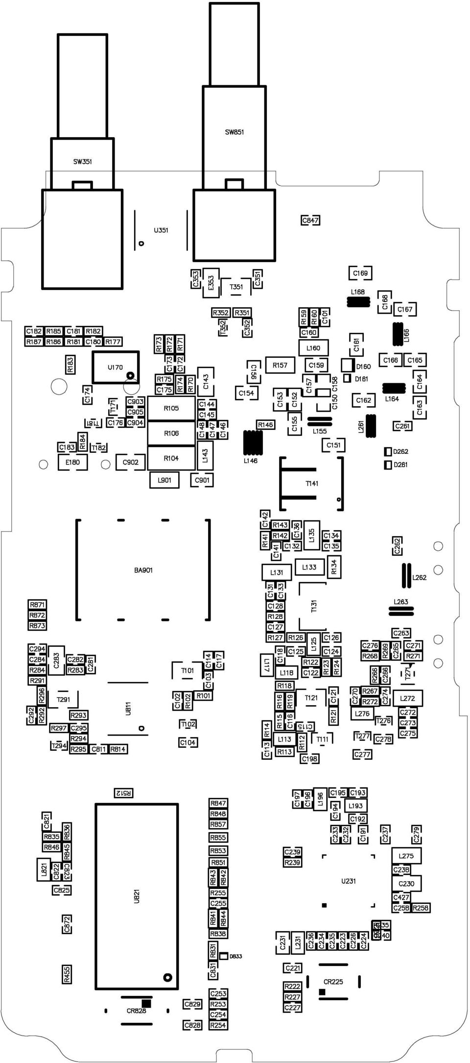
12 E D C B A 5 6 VDD Out GND NU NU 6 VDD COUT VDD VDD 5 6 CBC NU CLK NU 7 0 DATA NU 8 NU GND Vcc A0 WP A 6 CK A 5 DA GND 5C VC 6 XOUT GND AVDD SCLK SDIO AVDD XTAL XTAL MODE SENB Cc PDN AVDD PABIAS AVDD RFOUT T O VCC O GND IN- 8 IN+ IN out in E D C B A TX_P TX_P T T T T T SW87 ALARM SW85 PTT SW8 CALL SW8 MONI SW85A SW-6 R87 00K D875 LED(R) R875.5K T875 DTCEE C876 R87 5K R8 C87 C85 C8 C8 D877 LED(G) R877 T877 DTCEE R8 R87 0K R85 0 R85 0 R856 0 R858 0 R86 C878 C87 R88 R857 C858 R87 K7 R85 K7 R8 K7 R8 K7 R855 C856 RX_LED TX_LED BATDET R85 C85 R85 C85 PTT ALARM D8 CH CH CH CH C8 R8 0K C8 RDA_SDIO/CALL MONI/BEEP TX_LED C8 R8 T8 U8 RQ7A C89 P C88 P CR88.768KHz RDA_SQ VOX_DET RDA_PDN CHORD_SCLK BATDET RDA_SCLK/PTT APC P 7 _ 6 OS C I P 7 _ 5 OS C O P 7 _ R E S E T P 7 _ P 5 _ 0 ALARM RXD RXD P 7 _ P 5 _ P 7 _ P 5 _ R D A _ S D IO /C A L L P 7 _ 0 P 5 _ RDA_CODE IN/OUT RX_LED RDA_SCLK/PTT PTT C85 V C C P 5 _ V D D P 5 _ 5 V S S P 5 _ 6 P 6 _ 7 P 6 _ 0 P 6 _ 6 P 6 _ P 6 _ 5 6 P 6 _ RDA_CSS IN/OUT MONI/BEEP CH CH CH CH TX_LED P 6 _ P 6 _ CHORD_SCLK R5 0K RDA_INT RDA_SCLK/PTT RDA_PDN VOX_DET RDA_SQ APC TXD C8 L8 0T C8 U8 SMP8UD-0600 R5 K R5 5 R5 K C5 C55 U5 AUDIO-6 C8 NU NU 5 R55 56K RDA_CODE IN/OUT RDA_CSS IN/OUT C5 RDA_SDIO/CALL APC APC P_AMP P_AMP TXD TXD VOX_DET VOX_DET R8 0K C8 R K C MONI/BEEP R55 M R D A _C OD E I N / OU T R D A _S D I O/C A LL RV 50K D5 KDS C55 C0 U8 C08 R7 R55 K7 C55 7P TXD RXD C5 APC P_AMP R0 P_AMP RDA_INT CR5 6MHz T0 SB6 C0 RDA_CSS IN/OUT RDA_SCLK/PTT RDA_PDN RDA_SQ C7 T5 MRF97 R5 K7 C 0P R5 K R5 70K R9 0K C5 C6 0P C C5 7P C5 R5 8K R5 0 C56 C C0 R0 K C9 C5 05P R5 R6 C5 T0 DTCEE U RDA86 C58 R58 K GPIO0/CSS_IO GPIO/CODE_IO GPIO/INT GPIO/SDO AFOUT P_TX C0 _IN AVDD GPIO5/TXON 7 GPIO/RXON GPIO6/SQ GPIO7/VOX RFIN AVDD C0 0uF/6V C7 05P R7 R6 K7 L96 C95 C 0P C97 L9 C8 0P C9 C0 C C7 C98 C96 C9 C9 C9 L 0T C6 P_RX T L75 nh L R C7 C 05P C77 C7 C75 P C79 R R C5 R5 T77 DTCEE C7 C C C6 R7 L7 nh T7 SK8 R7 R9 K9 R6 K5 C T76 DTAYE C70 C7 L7 90NH L8 5NH T SC56 R R68 00K R69 00K C7 R8 C P L76 0T R67 00K R66 M C65 C8 R R C78 C76 C66 C7 C R APC C8 R7 L5 C5 R8 K T8 SK8 R8 00K R6 7R C6 C5 C8 C8 05P L 0T L 0./.5/T T HE078 R8 M C R 0P E80.7uF (T.Y.) U70B LM90V C5 C C 0P R86 K C C5 C 5P C7 C80 R8 R85 80K R L5.NH R77 0K R8 0K C8 C C6 R R 7R BATT T C76 L 0T L6 8T(05) T HE0009 U70A LM90V C75 00P R75 50K T C uf R6 L55 C5 R7 50K R7 50K C C6 C7 R7 50K R7 50K C5 C7 BATT T R70 50K C7 C8 T7 DTCEE E5 R8 C9 K R57 R59 T5 R5 SA6 E56 C56 R7 E5 uf uf/0v U5 C57 C59 00K R C UTC8 C60 C6 P T 8K KTC08(HF) R5 K R55 C55 K R5 C5 K T5 DTCEE C5 C5 7P RDA_SCLK/PTT RDA_SCLK/PTT RDA_SCLK/PTT TXD TXD TXD RXD RXD RXD AF AF AF APC AF i P_AMP P_AMP R87 0K T8 DTAYE C55 C58 C50 P R58 C5 E5 0uF TX_P R0 0. R05 0. R06 0. BATT C5 0P TXD RXD AF AF i BATT RDA_SCLK/PTT IN- SP- SP+ RXD TXD C5 P AF AF i R95 K7 C56 R57 0.*.*T L6 NH C6 P C9 C95 C57 5P L6 C6 8P R9 R59 7 C60 C59 00P C58 T9 DTCEE R85 0K BATT R60 7 L60 0NH D60 HVC D6 HVC D6 HSC77 R9 K T9 SB6 R97 0K C905 R88 0K R87 0 R86 0 R96 00K R9 00K C9 C6 P L6 T(0) C6 P E9 0uF/6V C90 C8 R9 K C9 C6 D6 HSC77 U9 CE60AP Gnd R8 C90 0uF/0V C6 P C6 P C66 P L6 L66 T(00) 5T(00) T8 SK8 C9 C9 C90 C65 6P E9 0uF/0V R8 7 R8 K C68 P5 L68 5T(00) C67 P J8 BATT C907 R8 K8 C8.7uF/6V L90 0T C90 05P C69 P C8 C906 L69 0K BA90 BATTERY ANT60 ANT- C8 0P R5 SW5A RD80S SP5 SP- JK5 ST JK8 ST-
 R877 T877 DTCEE R8 R87 0K R85 0 R85 0 R856 0 R858 0 R86 C878 C87 R88 R857 C858 R87 K7 R85 K7 R8 K7 R8 K7 R855 C856 RX_LED TX_LED BATDET R85 C85")
13 - I I Block Diagram + - LDF ANT PGA ADC ANT SW LNA + 0/90 Q PGA Q ADC PA RFOUT PA_drvier VCO DVDD.V LDO AVDD LDO Synthesize Benchmark frequencyinput AF AMP DSP Core Audio filter SubCH filter FM modem AFC loop RSSI DAC ADC GPIO Interface Bus LIMITER AMP HPF INT/GPIO SQ/GPIO VOX/GPIO PTT PTT PDN MCU SEN LAMP SCLK SDIO CTSIN CTSOUT MONI EODER

14 BOM MODEL speficition qty position number capacitance 0P5 C00 C7 5P C00 C6 C75 C7 0P C00 5 C C6 C C9 C8 P C00 C89 C88 5P C00 C6 C 7P C00 C6 C P C00 C 00P C00 C75 C00 9 C878 C876 C5 C5 C5 C8 C77 C8 C8 C7 C7 C76 C5 C C7 C8 C7 C0 R7 C00 5 C55 C9 C56 C9 C85 C8 C7 C C7 C C C8 C0 C90 C7 C00 9 C5 C9 C59 C58 C57 C55 C5 C5 C9 C5 C5 C78 C C8 C5 C66 C58 C6 C8 C8 C C5 C87 C8 C8 C0 C905 C70 C8 05P C00 C5 C7 C8 0P C00 C8 P C00 C C00 8 C907 C906 C858 C856 C85 C85 C85 C8 C8 C56 C76 C65 C60 C7 C6 C5 C C C C C80 C7 C0 C9 C95 C87 C9 C90 7P C00 C55 C5 7P C00 C5 P C060 C6 6P C060 C69 0P C060 C6 P C060 C68 C66 P C060 C67 0P C060 C65 P C060 C6 56P C060 C5 68P C060 C59 05P C060 C C90 C060 C6 0uF/0V(06P) C0805 C90 E9 E9 C0 uf(05p) C0805 C E5.7uF(75P) C0805 E80 C8 uf EIA6 E56 0uF E-06L E5 resistance R00 7 R R C C98 C6 C5 R6 K R00 6 R5 R8 R5 R5 R9 R5 K5 R00 R6 R875 K8 R00 R8 K R00 R0 R9 C55
 C0805 C90 E9 E9 C0 uf(05p) C0805 C E5.")
15 K9 R00 R9 K7 R00 8 R95 R85 R8 R8 R55 R5 R87 R6 8K R00 R 0K R00 0 R9 R8 R88 R87 R77 R87 R8 R85 R97 R8 R00 5 R59 R58 R57 R5 R K R00 R58 K R00 R K R00 R55 R86 R00 7 R8 R5 R8 R857 R855 R85 R85 R9 R7 R R R7 R88 R86 R8 R8 R0 7R R00 R R6 5K R00 R87 56K R00 R55 8K R00 R5 00K R00 8 R9 R96 R69 R68 R67 R8 R87 R7 0 R00 7 R87 R858 R856 R85 R85 R5 R86 50K R00 6 R75 R7 R7 R7 R7 R70 80K R00 R85 0K R00 R8 R00 R5 R877 7 R00 R60 R59 0K R00 R5 R00 R7 R7 R8 70K R00 R5 7 R00 R8 5 R00 R5 68 R00 R8 M R00 R55 R66 R8 R060 R L96 L9 L5 R0805 R57 0K R06 L R06 R06 R05 R0 50K RV08 RV induction 7NH L060 L6 L5 00NH L060 L8 L6 L75 0nH L060 L7 L60 90NH L060 L7 0T L060 L76 L8 L 0T L0805 L L L90 0.*.5*5T 5T L L6 0.*.5*6T 6T L6 L68 L66 0.*.5*8T 8T L6 0.*.*T T L55 diode LED(G) D060 D877 LED(R) D060 D875 HSC77 D-ESC D6 D6 HVC D-ESC D6 D60 KDS D-USM-MA7 D5 audion RQA0009 T-NA-SK76 T

16 SK8 T-ESM-SK8 T8 T8 DTAYE T-ESM-DTAEE T76 T8 DTCEE T-ESM-DTAEE 7 T877 T875 T5 T77 T0 T9 T7 078 T-SOT89-SK078 T SA6 T-TSM-SB6 T5 SB6 T-TSM-SB6 T9 T0 SC56 T-TSM-SC56(R5) T RQ7A T-US U8 SK8 T-US-SK8 T7 MRF97 T-USM-MRF97 T5 KTC08(HF) T-USM-MRF97 T integration RDA86 U-QFN(RDA86) U AUDIO-6 U-SOIC6 U5 SMP8VD-0800 U-SOP8 U8 C08 U-SOP8 U8 UTC8 U-SOP8 U5 HT7 U-SOT89-5A U9 LM90V U-SSOP8 U70 other 6MHz FX-DS005 CR5.768KHz FX-DS060 CR88 BATTERY JK-C BC-7S--D BA90 SP- JP-SM.7- SP5 PTT S-SKRT- SW85 CALL S-SS08GS6 SW8 MONI S-SS08GS6 SW8 BATT J-TEST POINT J8 pinouts ANT- PX--ANT ANT SW-6 S-ED08CO SW85 RD80S S-R087FENS SW5 ST- JK-ST-06 JK8 ST-0-06 JK-ST-0-06 JK5 ALARM S-SKHLLBA00 SW87 PCB CW5080-0

17 Chip Pin Description Pin No. Pin Name Function description OSCI Clock crystal input pin OCSO Clock crystal output pin RESER Reset pin ALARM Alarm key detection pin 5 RXD read and write frequency data 6 RDA_SDIL/CALL RDA SDIL and CALL key control pin 7 RDA_CEDE IN/OUT 86 data input/output pin 8 RDA_CSS IN/OUT 86 CTCSS input/output pin 9 MONI/BEEP squelch key/beep control pin 0 CH encoder control pin CH encoder control pin CH encoder control pin CH encoder control pin TX_LED transmit indicator light 5 RDA_INT 86 data control pin 6 RX_LED receive indicator light 7 TXD read and write frequency data 8 PTT PTT key control pin 9 VSS ground pin 0 VDD power VCC APC auto power control RDA_SCLK/PTT 86 data control pin BATDET power detection pin 5 RDA_SEN 86 data control pin 6 RDA_PDN 86 data control pin 7 VOX-DET VOX detection pin 8 RDA_SQ squelch control pin

18 SPECIFICATION Frequency Range 00-70MHz Channel Number 6 Channel Step Antenna Impedance Microphone Impedance work voltage Frequency Stability.5KHz 50Ω KΩ 7.V DC ± ppm Transmitter carrier output power modulation sensitivity 5W 8-mV Modulation Distortion 5% Modulation Limited Adjacent Channel Power Intermodulatohn Rejection 5KHz 65dB 0dB RECEIVER Sensitivity 0.uV Audio Distortion 5% SN RATE -0 Co-Channel Rejection Blocking Adjacent Channel Selectivity Spurious Radiation -8dB 85dB 55dB 55dB

MJ-327 VHF FM TRANSCEIVERS
 SERVICE MANUAL MJ- VHF FM TRANSCEIVERS SPECIFICATIONS GENERAL Frequencyy Range Workingg Temperate --MHz -0 ~+ Operating Voltage DC.V Current Consumption.A(transmit W) Sensitivity Adjust Antenna impedance
VMR6512 Hi-Fi Audio FM Transmitter Module
 General Description VMR6512 is a highly integrated FM audio signal transmitter module. It integrates advanced digital signal processor (DSP), frequency synthesizer RF power amplifier and matching network.
Tire pressure monitoring
 Application Note AN601 Tire pressure monitoring 1 Purpose This document is intended to give hints on how to use the Intersema pressure sensors in a low cost tire pressure monitoring system (TPMS). 2 Introduction
Features. Applications. Transmitter. Receiver. General Description MINIATURE MODULE. QM MODULATION OPTIMAL RANGE 1000m
 Features MINIATURE MODULE QM MODULATION OPTIMAL RANGE 1000m 433.05 434.79 ISM BAND 34 CHANNELS AVAILABLE SINGLE SUPPLY VOLTAGE Applications IN VEHICLE TELEMETRY SYSTEMS WIRELESS NETWORKING DOMESTIC AND
MAINTENANCE & ADJUSTMENT
 MAINTENANCE & ADJUSTMENT Circuit Theory The concept of PLL system frequency synthesization is not of recent development, however, it has not been a long age since the digital theory has been couplet with
DRM compatible RF Tuner Unit DRT1
 FEATURES DRM compatible RF Tuner Unit DRT1 High- Performance RF Tuner Frequency Range: 10 KHz to 30 MHz Input ICP3: +13,5dBm, typ. Noise Figure @ full gain: 14dB, typ. Receiver Factor: -0,5dB, typ. Input
GTS-4E Hardware User Manual. Version: V1.1.0 Date: 2013-12-04
 GTS-4E Hardware User Manual Version: V1.1.0 Date: 2013-12-04 Confidential Material This document contains information highly confidential to Fibocom Wireless Inc. (Fibocom). Fibocom offers this information
ZLPLL Local Oscillator
 ZLPLL Local Oscillator Wayne Knowles, ZL2BKC w.knowles@xtra.co.nz Contents 1 Introduction... 3 2 Specifications... 3 3 Performance... 4 3.1 Phase Noise... 4 3.2 Output Level... 4 3.3 Harmonic Level...
Chapter 6 PLL and Clock Generator
 Chapter 6 PLL and Clock Generator The DSP56300 core features a Phase Locked Loop (PLL) clock generator in its central processing module. The PLL allows the processor to operate at a high internal clock
Rayson Technology Co., Ltd.
 Rayson Bluetooth Module BC05-MM Class2 Stereo Module BTM-730 Features The module is a Max.4dBm( Class2 ) module. Fully Qualified Bluetooth v2.0+edr system. Integrated Switched-Mode Regulator. Integrated
Part Number Description Packages available
 Features 3 digital I/O Serial Data output Connects directly to RF Modules Easy Enc / Dec Pairing Function Minimal External Components Required Performs all encoding/decoding of data for Reliable Operation.
RX-AM4SF Receiver. Pin-out. Connections
 RX-AM4SF Receiver The super-heterodyne receiver RX-AM4SF can provide a RSSI output indicating the amplitude of the received signal: this output can be used to create a field-strength meter capable to indicate
Lecture 1: Communication Circuits
 EECS 142 Lecture 1: Communication Circuits Prof. Ali M. Niknejad University of California, Berkeley Copyright c 2005 by Ali M. Niknejad A. M. Niknejad University of California, Berkeley EECS 142 Lecture
Wireless Security Camera
 Wireless Security Camera Technical Manual 12/14/2001 Table of Contents Page 1.Overview 3 2. Camera Side 4 1.Camera 5 2. Motion Sensor 5 3. PIC 5 4. Transmitter 5 5. Power 6 3. Computer Side 7 1.Receiver
NTE2053 Integrated Circuit 8 Bit MPU Compatible A/D Converter
 NTE2053 Integrated Circuit 8 Bit MPU Compatible A/D Converter Description: The NTE2053 is a CMOS 8 bit successive approximation Analog to Digital converter in a 20 Lead DIP type package which uses a differential
Web Site: www.parallax.com Forums: forums.parallax.com Sales: sales@parallax.com Technical: support@parallax.com
 Web Site: www.parallax.com Forums: forums.parallax.com Sales: sales@parallax.com Technical: support@parallax.com Office: (916) 624-8333 Fax: (916) 624-83 Sales: (888) 512-124 Tech Support: (888) 997-8267
Kenwood introduces. new HF/50MHz All-Mode Transceiver
 New Product Release Information Oct 2014 TS-590SG HF/ 50MHz All-Mode TRANSCEIVER_ Kenwood introduces Updated to new G version new HF/50MHz All-Mode Transceiver Four years ago we launched our best-selling
How to Simplify the Design of an RF Remote Control Using a Highly-Integrated Transmitter SoC
 How to Simplify the Design of an RF Remote Control Using a Highly-Integrated Transmitter SoC Designing radio frequency (RF) remote controls has never been easier thanks to the advent of highlyintegrated,
FM TRANSMITTER & RECEIVER HYBRID MODULES. FM-RTFQ SERIES FM-RRFQ SERIES. Transmitter. Receiver. Applications
 FM Radio Transmitter & Receivers Available as or or 868MHz Transmit Range up to 20m Miniature Packages Data Rate up to 9.6Kbps No Adjustable Components Very Stable Operating Frequency Operates from 20
Content. Maintenance. Features ENGLISH. 1 transceiver 1 antenna 1 battery pack 1 belt clip 1 fast desktop charger User manual
 Contents Maintenance... 2 Features... 2 Main indicators/controls... 3 LCD display... 5 Basic operations... 6 Advanced operations... 15 Menu operations Self-Programming mode... 17 Self-programming chart...
Rayson. Bluetooth Module
 Rayson Class2 BC04-ext Module Features Bluetooth Module BTM-182 Outline Class2 module with printed pcb antenna Bluetooth standard Ver. 2.1 + EDR compliant. Low current consumption : Hold,Sniff,Park,Deep
VHF COMMUNICATION TRANSCEIVER
 ATR-500 VHF COMMUNICATION TRANSCEIVER ON OFF OPERATION MANUAL Manual Number 01.125.010.08 REVISION 1.3, Jan 20. 2005 from S/N 00301 04 Contents 1 SECTION 1 GENERAL INFORMATION...3 1.1 INTRODUCTION...3
RDF1. RF Receiver Decoder. Features. Applications. Description. Ordering Information. Part Number Description Packages available
 RDF1 RF Receiver Decoder Features Complete FM Receiver and Decoder. Small Form Factor Range up to 200 Metres* Easy Learn Transmitter Feature. Learns 40 transmitter Switches 4 Digital and 1 Serial Data
Using the Teridian 73M2901CE in 4-Wire and Leased Line Applications
 A Maxim Integrated Products Brand 7M90CE V. bis Single Chip Modem APPLICATION NOTE AN_90CE_0 February 009 Introduction Using the Teridian 7M90CE in -Wire and Leased Line Applications The Teridian 7M90
FM TRANSMITTER & RECEIVER HYBRID MODULES. FM-RRFQ SERIES. Transmitter. Receiver. Applications
 FM Radio Transmitter & Receivers Available As or or 88MHz Transmit Range Up To 0m Miniature Packages Data Rate upto 9.Kbps No Adjustable Components Very Stable Operating Frequency Operates from 0 to +8
A RF18 Remote control receiver MODULE
 A RF18 Remote control receiver MODULE User Guide No part of this document may be reproduced or transmitted (in electronic or paper version, photocopy) without Adeunis RF consent. This document is subject
M80 EVB User Guide M80. Quectel Cellular Engine. EVB User Guide M80_EVB_UGD_V1.2 M80_EVB_UGD_V1.2-0-
 M80 Cellular Engine EVB User Guide M80_EVB_UGD_V1.2 M80_EVB_UGD_V1.2-0- Document Title M80 EVB User Guide Version 1.2 Date 2012-08-13 Status Document Control ID Released M80_EVB_UGD_V1.2 General Notes
CMOS 5GHz WLAN 802.11a/n/ac RFeIC WITH PA, LNA, AND SPDT
 CMOS 5GHz WLAN 802.11a/n/ac RFeIC WITH PA, LNA, AND SPDT Description RFX8055 is a highly integrated, single-chip, single-die RFeIC (RF Front-end Integrated Circuit) which incorporates key RF functionality
A CW QRP Transceiver for 20 m band. How it works I'll describe individually the three boards and the relative tuning devices.
 A CW QRP Transceiver for 20 m band The little QRP presented in this article may be built in a gradual manner, in fact it is divided in two main modules (plus VFO), you may also complete only a single part
24-Bit Analog-to-Digital Converter (ADC) for Weigh Scales FEATURES S8550 VFB. Analog Supply Regulator. Input MUX. 24-bit Σ ADC. PGA Gain = 32, 64, 128
 for Weigh Scales FEATURES S8550 VFB. Analog Supply Regulator. Input MUX. 24-bit Σ ADC. PGA Gain = 32, 64, 128") 24-Bit Analog-to-Digital Converter (ADC) for Weigh Scales DESCRIPTION Based on Avia Semiconductor s patented technology, HX711 is a precision 24-bit analogto-digital converter (ADC) designed for weigh
24-Bit Analog-to-Digital Converter (ADC) for Weigh Scales DESCRIPTION Based on Avia Semiconductor s patented technology, HX711 is a precision 24-bit analogto-digital converter (ADC) designed for weigh
Board Layout & Guidelines Using the
 Board Layout & Guidelines Using the AM/FM Tuner from Silicon Labs Agenda Company overview Broadcast audio product portfolio Si473x block diagram and technical highlights g Design and layout guidelines
USB to serial chip CH340
 The DataSheet of CH340 (the first) 1 1. Introduction USB to serial chip CH340 English DataSheet Version: 1D http://wch.cn CH340 is a USB bus convert chip and it can realize USB convert to serial interface,
AN383. Si47XX ANTENNA, SCHEMATIC, LAYOUT, AND DESIGN GUIDELINES. 1. Introduction
 Si47XX ANTENNA, SCHEMATIC, LAYOUT, AND DESIGN GUIDELINES 1. Introduction This document provides general Si47xx design guidelines and AM/FM/SW/LW/WB antenna selections which includes schematic, BOM, layout
AMIS-52150. Low power Transceiver with Clock and Data Recovery
 AMIS-52150 Low power Transceiver with Clock and Data Recovery Introduction The AMIS 52150 is a cost-effective, ultra-low power single-chip wireless transceiver. It combines the proven Amplitude Shift Key/On-Off
FLYPORT Wi-Fi 802.11G
 FLYPORT Wi-Fi 802.11G System on module 802.11g WIFI - Infrastructure mode - softap mode - Ad hoc mode Microchip PIC 24F 16 bit processor Microchip MRF24WG0MA/MB - Native WiFi 802.11g transceiver - PCB
TS5010 TeraTune Programmable Bandpass Filter
 FEATURES 0MHz to 90MHz Tunability 240 Frequency Steps Constant Q, Two-pole Butterworth Bandpass 1W Power Handling 0µs Tuning Speed Serial/Parallel Modes -40C to +85C DESCRIPTION The TS5010 series of TeraTune
Turbo X. www.smartwireless.co.uk. 594 channel UHF true diversity
 Turbo X 594 channel UHF true diversity The new Turbo X series from Smart Wireless is the culmination of two years of research and development into advanced wireless technology. Using sophisticated RF design
US-SPI New generation of High performances Ultrasonic device
 US-SPI New generation of High performances Ultrasonic device Lecoeur Electronique - 19, Rue de Courtenay - 45220 CHUELLES - Tel. : +33 ( 0)2 38 94 28 30 - Fax : +33 (0)2 38 94 29 67 US-SPI Ultrasound device
Pmod peripheral modules are powered by the host via the interface s power and ground pins.
 Digilent Pmod Interface Specification Revision: November 20, 2011 1300 NE Henley Court, Suite 3 Pullman, WA 99163 (509) 334 6306 Voice (509) 334 6300 Fax Introduction The Digilent Pmod interface is used
TDA7318D DIGITAL CONTROLLED STEREO AUDIO PROCESSOR
 TDA738 DIGITAL CONTROLLED STEREO AUDIO PROCESSOR INPUT MULTIPLEXER: - 4 STEREO INPUTS - SELECTABLE INPUT GAIN FOR OPTIMAL ADAPTION TO DIFFERENT SOURCES INPUT AND OUTPUT FOR EXTERNAL EQUALIZER OR NOISE
ADS9850 Signal Generator Module
 1. Introduction ADS9850 Signal Generator Module This module described here is based on ADS9850, a CMOS, 125MHz, and Complete DDS Synthesizer. The AD9850 is a highly integrated device that uses advanced
Class2 BC04-ext Module
 Rayson Class2 BC04-ext Module Features Bluetooth Module BTM-112 Outline The module is a Max.4( Class2 ) module. Bluetooth standard Ver. 2.0 + EDR conformity. Internal 1.8V regulator Low current consumption
HARDWARE MANUAL. BrightSign HD120, HD220, HD1020. BrightSign, LLC. 16795 Lark Ave., Suite 200 Los Gatos, CA 95032 408-852-9263 www.brightsign.
 HARDWARE MANUAL BrightSign HD120, HD220, HD1020 BrightSign, LLC. 16795 Lark Ave., Suite 200 Los Gatos, CA 95032 408-852-9263 www.brightsign.biz TABLE OF CONTENTS OVERVIEW... 1 Block Diagram... 2 Ports...
FM Radio Transmitter & Receiver Modules
 FM Radio Transmitter & Receiver Modules T5 / R5 Features MINIATURE SIL PACKAGE FULLY SHIELDED DATA RATES UP TO 128KBITS/S RANGE UPTO 300 METRES SINGLE SUPPLY VOLTAGE INDUSTRY PIN COMPATIBLE QFMT5-434 TEMP
INTEGRATED CIRCUITS DATA SHEET. TDA7000 FM radio circuit. Product specification File under Integrated Circuits, IC01
 INTEGRATED CIRCUITS DATA SHEET File under Integrated Circuits, IC01 May 1992 GENERAL DESCRIPTION The is a monolithic integrated circuit for mono FM portable radios, where a minimum on peripheral components
Interfacing Analog to Digital Data Converters
 Converters In most of the cases, the PIO 8255 is used for interfacing the analog to digital converters with microprocessor. We have already studied 8255 interfacing with 8086 as an I/O port, in previous
VJ 6040 Mobile Digital TV UHF Antenna Evaluation Board
 VISHAY VITRAMON Multilayer Chip Capacitors Application Note GENERAL is a multilayer ceramic chip antenna designed for receiving mobile digital TV transmissions in the UHF band. The target application for
U10 EVB User Guide U10. Quectel Cellular Engine. EVB User Guide U10_EVB_UGD_V1.0 U10_EVB_UGD_V1.0-1 -
 U10 Cellular Engine EVB User Guide U10_EVB_UGD_V1.0 U10_EVB_UGD_V1.0-1 - Document Title EVB User Guide Version 1.0 Date 2012-03-01 Status Document Control ID Released U10_EVB_UGD_V1.0 General Notes offers
Optimizing VCO PLL Evaluations & PLL Synthesizer Designs
 Optimizing VCO PLL Evaluations & PLL Synthesizer Designs Today s mobile communications systems demand higher communication quality, higher data rates, higher operation, and more channels per unit bandwidth.
Voice Dialer Speech Recognition Dialing IC
 Speech Recognition Dialing IC Speaker Dependent IC for Voice Dialing Applications GENERAL DESCRIPTION The IC, from the Interactive Speech family of products, is an application specific standard product
Simple SDR Receiver. Looking for some hardware to learn about SDR? This project may be just what you need to explore this hot topic!
 Michael Hightower, KF6SJ 13620 White Rock Station Rd, Poway, CA 92064; kf6sj@arrl.net Simple SDR Receiver Looking for some hardware to learn about SDR? This project may be just what you need to explore
FEATURES DESCRIPTION APPLICATIONS BLOCK DIAGRAM. PT2248 Infrared Remote Control Transmitter
 Infrared Remote Control Transmitter DESCRIPTION PT2248 is an infrared remote control transmitter utilizing CMOS Technology. It is capable of 18 functions and a total of 75 commands. Single-shot and continuous
Digital Guitar Effects Pedal
 Digital Guitar Effects Pedal 01001000100000110000001000001100 010010001000 Jonathan Fong John Shefchik Advisor: Dr. Brian Nutter SPRP499 Texas Tech University jonathan.fong@ttu.edu Presentation Outline
IrDA Transceiver with Encoder/Decoder
 PRELIMINARY IrDA Transceiver with Encoder/Decoder FEATURES Micropower in the Sleep Mode, (2µA) 3V to 5V Operation Wide Dynamic Receiver Range from 200nA to 50mA Typical Direct Interface to IrDA Compatible
U4224B. Time-Code Receiver with Digitized Serial Output. Description. Features. Block Diagram
 UB Time-Code Receiver with Digitized Serial Output Description The UB is a bipolar integrated straight-through receiver circuit in the frequency range of 0 to 0 khz. The device is designed for radio-controlled
Absolute maximum. User Manual
 RTX-MID-3V/ is an RF digital data transceiver working on the ISM free-license band of 433.92 MHz, in half-duplex way, ASK modulated and fast switch time TX RX and RX TX. It s ideal for low cost solutions,
TS34119 Low Power Audio Amplifier
 SOP-8 DIP-8 Pin assignment: 1. CD 8. VO2 2. FC2 7. Gnd 3. FC1 6. Vcc 4. Vin 5. VO1 General Description The TS34119 is a low power audio amplifier, it integrated circuit intended (primarily) for telephone
US-Key New generation of High performances Ultrasonic device
 US-Key New generation of High performances Ultrasonic device US-Key connected to a laptop computer US-Key Ultrasound device single channel Features USB2 High Speed connection Ultralow noise preamplifier
How To Use A Sound Card With A Subsonic Sound Card
 !"## $#!%!"# &"#' ( "#' )*! #+ #,# "##!$ -+./0 1" 1! 2"# # -&1!"#" (2345-&1 #$6.7 -&89$## ' 6! #* #!"#" +" 1##6$ "#+# #-& :1# # $ #$#;1)+#1#+
Wireless Temperature
 Wireless Temperature connected freedom and Humidity Sensor Using TELRAN Application note TZ1053AN-06 Oct 2011 Abstract Dr. C. Uche This application note describes the complete system design (hardware and
LM 358 Op Amp. If you have small signals and need a more useful reading we could amplify it using the op amp, this is commonly used in sensors.
 LM 358 Op Amp S k i l l L e v e l : I n t e r m e d i a t e OVERVIEW The LM 358 is a duel single supply operational amplifier. As it is a single supply it eliminates the need for a duel power supply, thus
TOTALLY SOLID STATE NON-DIRECTIONAL RADIO BEACONS 190-535 khz
 TOTALLY SOLID STATE NON-DIRECTIONAL RADIO S 190-535 khz This family of radio transmitters has been developed as extremely efficient, highly reliable Non Directional Beacons. ND2000A/4000A» MODULAR CONSTRUCTION»
FM/AM RADIO IC CD2003GP/GB. 1 Overview. 2 Block Diagram And Pin Descriptions
 CD2003GP/GB FM/AM RADIO IC 1 Overview The CD2003GP/GB is a monolithic IC designed for use as a FM/AM radio system. Combined with audio power amplifier IC, a suitable FM/AM radio can be constituted. Its
ic- 2730a (USA, EXP) ic- 2730e (Europe)
 ic- 2730e (Europe)") November 2014 VHF/UHF DUAL BAND TRANSCEIVERS ic- 2730a (USA, EXP) ic- 2730e (Europe) Icom proudly announces the debut of the new VHF/UHF dual band transceiver, IC-2730A/2730E. It is the successor of the
November 2014 VHF/UHF DUAL BAND TRANSCEIVERS ic- 2730a (USA, EXP) ic- 2730e (Europe) Icom proudly announces the debut of the new VHF/UHF dual band transceiver, IC-2730A/2730E. It is the successor of the
ET-BASE AVR ATmega64/128
 ET-BASE AVR ATmega64/128 ET-BASE AVR ATmega64/128 which is a Board Microcontroller AVR family from ATMEL uses MCU No.ATmega64 and ATmega128 64PIN. Board ET-BASE AVR ATmega64/128 uses MCU s resources on
Massachusetts Institute of Technology Department of Electrical Engineering and Computer Science. 6.002 Electronic Circuits Spring 2007
 Massachusetts Institute of Technology Department of Electrical Engineering and Computer Science 6.002 Electronic Circuits Spring 2007 Lab 4: Audio Playback System Introduction In this lab, you will construct,
Wireless monitoring system for temperature and humidity based on ZigBee
 Wireless monitoring system for temperature and humidity based on ZigBee Abstract Jianjun Chen* Shaoxing University uanpei College, Shaoxing, Zhejiang, 3000, China Received March 04, www.cmnt.lv Traditional
MG2639 Module Hardware Design User Manual. Version:V1.0
 MG2639 Module Hardware Design User Manual Version:V1.0 Copyright Statement Copyright 2010 by ZTE Corporation All rights reserved. No part of this publication may be excerpted, reproduced, translated or
ULC Technology: High-performance gate array package using multiple metal layer CMOS technology featuring sub-micron channel lengths (0.
 SIR Endec for IrDA Applications Integrated Interface Circuits TOIM ULC Technology: High-performance gate array package using multiple metal layer CMOS technology featuring sub-micron channel lengths (0.
THE R551N RECEIVER FAQ FAULT FINDING THE REDIFON COMMUNICATIONS RECEIVER R551N. Date: October 10th 1995 by: Jan Verduyn G5BBL
 THE R551N RECEIVER FAQ FAULT FINDING THE REDIFON COMMUNICATIONS RECEIVER R551N Introduction: Date: October 10th 1995 by: Jan Verduyn G5BBL Recently a number of Redifon R551N receivers have appeared on
Ignition Alert Anti-Theft Security System for Motorbikes with Remote Control Amit Yadav, Anushri Jha, Neelesh Gupta amitrinku007@yahoo.
 Ignition Alert Anti-Theft Security System for Motorbikes with Remote Control Amit Yadav, Anushri Jha, Neelesh Gupta amitrinku007@yahoo.com Abstract There are many vehicle security system are available
A Low Frequency Adapter for your Vector Network Analyzer (VNA)
") Jacques Audet, VE2AZX 7525 Madrid St, Brossard, QC, Canada J4Y G3: jacaudet@videotron.ca A Low Frequency Adapter for your Vector Network Analyzer (VNA) This compact and versatile unit extends low frequency
Jacques Audet, VE2AZX 7525 Madrid St, Brossard, QC, Canada J4Y G3: jacaudet@videotron.ca A Low Frequency Adapter for your Vector Network Analyzer (VNA) This compact and versatile unit extends low frequency
8051 Serial Port. Crystal TXD. I/O Device RXD. Embedded Systems 1 5-1 8051 Peripherals
 8051 Serial Port The 8051 contains a UART Universal Asynchronous Receiver Transmitter The serial port is full-duplex It can transmit and receive simultaneously 2 Port 3 pins are used to provide the serial
Department of Electrical and Computer Engineering Ben-Gurion University of the Negev. LAB 1 - Introduction to USRP
 Department of Electrical and Computer Engineering Ben-Gurion University of the Negev LAB 1 - Introduction to USRP - 1-1 Introduction In this lab you will use software reconfigurable RF hardware from National
SAH2217 Enhanced ATHEROS GPS Module with ultra high sensitivity and antenna open/short detection/protection
 SAH2217 Enhanced ATHEROS GPS Module with ultra high sensitivity and antenna open/short detection/protection 20F-8, No.107, Sec 1,Jhongshan Rd. Sinjhuang City, Taipei County 242, Taiwan Phone: +886-2-8522-7628
Preliminary and proprietary Information of YAMAR Electronics Ltd. Subject to change without notice.
 YAMAR Electronics Ltd Preliminary Data Sheet - UART over Powerline, for AC/DC Multiplex Network This information is preliminary and may be changed without notice 1 GENERAL The is a second generation transceiver
SM1231 USER GUIDE SM1231 RF MODULE USER GUIDE
 SM1231 RF MODULE Revision 1.0 11/2009 Page 1 of 8 www.semtech.com Table of Contents Table of Contents...2 Index of Figures...2 Index of Tables...2 1 Introduction...3 2 Reference Design...3 3 PCB Layout...6
DX 2517. AM FM SSB CW PA Amateur Base Station Transceiver OWNER S MANUAL RX / TX 2 4 POWER NF CHANNEL MODE RF POWER OFF CAL OFF OFF CALIBRATE
 1 2 3 6 4050 ULA 6070 TI 80 90 100 9 DX 2517 2517 RX / TX 0 2 4 SWR WATTS SET 81012 22 1 010 3 2030 5 MOD 7 ON dbover 9 SIGNAL +20 +40+60 PA FM AM USB LSB CW POWER ON SWR NB / ANL R.BEEP +10KHz NF CHANNEL
Product Information S N O. Portable VIP protection CCTV & Alarm System 2
 Product Information S N O Portable VIP protection CCTV & Alarm System 2 G O V E R N M E N T A L S E C U R I T Y S O L U T I VIP KIT Rapid Deployment VIP Protection Kit The VIP KIT has been designed to
Introduction to Receivers
 Introduction to Receivers Purpose: translate RF signals to baseband Shift frequency Amplify Filter Demodulate Why is this a challenge? Interference (selectivity, images and distortion) Large dynamic range
Micro-Step Driving for Stepper Motors: A Case Study
 Micro-Step Driving for Stepper Motors: A Case Study N. Sedaghati-Mokhtari Graduate Student, School of ECE, University of Tehran, Tehran, Iran n.sedaghati @ece.ut.ac.ir Abstract: In this paper, a case study
Alpha 10 SERVICE MANUAL. Downloaded from www.cbradio.nl. MAX 10 Meter Amateur Transceiver AM/FM/CW/SSB 6 BAND PROGRAMMABLE MODEL AM-1000.
 Alpha 10 MAX 10 Meter Amateur Transceiver MODEL AM-1000 AM/FM/CW/SSB 6 BAND PROGRAMMABLE SERVICE MANUAL Downloaded from www.cbradio.nl Cover Page LOUDER TALKBACK MOD Alpha 10 Max - Model AM-1000 4.7K Resistor
Maintenance Manual. VIRTUAL SITE 800 MHz (DTES-800 EDACS SITE EXTENDER) ericssonz LBI-39147 TABLE OF CONTENTS
 ericssonz LBI-39147 TABLE OF CONTENTS") Maintenance Manual VIRTUAL SITE 800 MHz (DTES-800 EDACS SITE EXTENDER) TABLE OF CONTENTS RF BOARD 19D902123G20...LBI-38841 RF BOARD 19D902123G22...LBI-38849 ericssonz NOTICE! This manual covers Ericsson
Maintenance Manual VIRTUAL SITE 800 MHz (DTES-800 EDACS SITE EXTENDER) TABLE OF CONTENTS RF BOARD 19D902123G20...LBI-38841 RF BOARD 19D902123G22...LBI-38849 ericssonz NOTICE! This manual covers Ericsson
AND8336. Design Examples of On Board Dual Supply Voltage Logic Translators. Prepared by: Jim Lepkowski ON Semiconductor. http://onsemi.
 Design Examples of On Board Dual Supply Voltage Logic Translators Prepared by: Jim Lepkowski ON Semiconductor Introduction Logic translators can be used to connect ICs together that are located on the
Baseband delay line QUICK REFERENCE DATA
 FEATURES Two comb filters, using the switched-capacitor technique, for one line delay time (64 µs) Adjustment-free application No crosstalk between SECAM colour carriers (diaphoty) Handles negative or
Homebuilt HF Radios for Use Underground Paul R. Jorgenson KE7HR
 Homebuilt HF Radios for Use Underground Paul R. Jorgenson KE7HR With the good success in using Amateur Band HF radio for underground communications, I started looking for cheaper alternatives to the $500+
LC7218, 7218M, 7218JM
 Ordering number : EN4758B CMOS LSI LC7218, 7218M, 7218JM PLL Frequency Synthesizer for Electronic Tuning in AV Systems Overview The LC7218, LC7218M and LC7218JM are PLL frequency synthesizers for electronic
HAC-LM Series Low Power Data Radio Module
 HAC-LM Series Low Power Data Radio Module Version 3.0 SHENZHEN HAC TELECOM TECHNOLOGY CO., LTD Address : 3rd Area, 19 th Fl, Tower A, HaiSong Building, Tai Ran 9 th Rd, Futian, ShenZhen, China. Tel : +86-755-23981078
AN437. Si4432 RF PERFORMANCE AND FCC COMPLIANCE TEST RESULTS. 1. Introduction. 2. Relevant Measurements to comply with FCC
 Si4432 RF PERFORMANCE AND FCC COMPLIANCE TEST RESULTS 1. Introduction This document provides measurement results and FCC compliance results for the Si4432B when operated from 902 928 MHz. The measurement
TRIPLE PLL FIELD PROG. SPREAD SPECTRUM CLOCK SYNTHESIZER. Features
 DATASHEET ICS280 Description The ICS280 field programmable spread spectrum clock synthesizer generates up to four high-quality, high-frequency clock outputs including multiple reference clocks from a low-frequency
VCO Phase noise. Characterizing Phase Noise
 VCO Phase noise Characterizing Phase Noise The term phase noise is widely used for describing short term random frequency fluctuations of a signal. Frequency stability is a measure of the degree to which
PCAN-MicroMod Universal I/O Module with CAN Interface. User Manual. Document version 2.1.0 (2014-01-16)
") PCAN-MicroMod Universal I/O Module with CAN Interface User Manual Document version 2.1.0 (2014-01-16) Products taken into account Product Name Part number Model PCAN-MicroMod IPEH-002080 with firmware
PCAN-MicroMod Universal I/O Module with CAN Interface User Manual Document version 2.1.0 (2014-01-16) Products taken into account Product Name Part number Model PCAN-MicroMod IPEH-002080 with firmware
SG901-1091 Miniature Wi-Fi Radio
 SG901-1091 Miniature Wi-Fi Radio Overview The SG901-1091 WiFi module is optimized to simplify successful integration into systems requiring the latest performance with small size. This module is a highly
Adding Heart to Your Technology
 RMCM-01 Heart Rate Receiver Component Product code #: 39025074 KEY FEATURES High Filtering Unit Designed to work well on constant noise fields SMD component: To be installed as a standard component to
ONCORE ENGINEERING NOTE UT Plus Oncore
 ONCORE ENGINEERING NOTE UT Plus Oncore 1. Product Description 2. Mechanical 3. Electrical 4. Pin-Out Diagram 5. EMC Considerations 6. RTC (Real Time Clock) 7. 1PPS Signal Description 8. TTL Serial Interface
nrf24l01 Single Chip 2.4GHz Transceiver Product Specification
 nrf24l01 Single Chip 2.4GHz Transceiver Product Specification Key Features Worldwide 2.4GHz ISM band operation Up to 2Mbps on air data rate Ultra low power operation 11.3mA TX at 0dBm output power 12.3mA
RD625. Digital Migration Radio. Wall Mount Repeater for Indoor. http://support.hytera.com. www.hytera.com
 Digital Migration Radio Wall Mount Repeater for Indoor Light, Small, Compact Design RF Power 1~25W with 100% Duty Cycle DMR & Analogue Auto Switch http://support.hytera.com www.hytera.com is a 25W, DMR
Spin Semiconductor FV-1 Reverb IC PN: SPN1001. Delay Memory DSP CORE. ROM and Program Control PLL. XTAL Drvr XTAL. Spin.
 Featuring Virtual Analog Technology PN: SPN1001 FEATURES Integrated stereo ADC and DAC 8 internal demonstration programs + 8 external programs Easy customization with external EEPROM 3 potentiometer inputs
AN-812 APPLICATION NOTE
 AN- APPLICATION NOTE One Technology Way P.O. Box 90 Norwood, MA 00-90, U.S.A. Tel: 7.9.700 Fax: 7.. www.analog.com Microcontroller-Based Serial Port Interface (SPI ) Boot Circuit by Alfredo Barriga INTRODUCTION
Memory Module Specifications KVR667D2D4F5/4G. 4GB 512M x 72-Bit PC2-5300 CL5 ECC 240-Pin FBDIMM DESCRIPTION SPECIFICATIONS
 Memory Module Specifications KVR667DD4F5/4G 4GB 5M x 7-Bit PC-5300 CL5 ECC 40- FBDIMM DESCRIPTION This document describes s 4GB (5M x 7-bit) PC-5300 CL5 SDRAM (Synchronous DRAM) fully buffered ECC dual