Application Note AN015
|
|
|
- Catherine Perkins
- 10 years ago
- Views:
Transcription
1 RF Modem Reference Design By K.H. Torvmark Keywords Reference design RS-232 CC1000 Application Example Modem Interfacing CC1000 with SPI Cable replacement Protocol example Microchip PIC Introduction This reference design for an RF modem demonstrates both low-level and protocollevel design using the CC1000 RF transceiver. Software and hardware are described in detail A pair of RF modems function as a wireless replacement for an ordinary RS- 232 serial cable. The modem will function with equipment and software supporting hardware handshaking and half-duplex communication. The function of the modem is completely transparent, but data rate, RF frequency and other parameters are user-definable. The hardware is designed as a motherboard in which a CC1000PP plugand-play module can be inserted. The use of modules allows the basic RF modem design to be used with different RF modules. The software handles transceiver configuration and data flow. SWRA076 Page 1 of 24

2 Table of Contents Description...3 Configuration...4 Basic operation...6 Hardware...6 Microcontroller...7 Temperature sensor...8 Schematics...9 Bill of materials...12 Software...14 Resource usage...14 Packet protocol...14 Source files...15 Software implementation...15 Main program...17 Interrupt handler...18 Operation...19 Performance...22 Modifications...23 Source code and PCB documentation...23 References...24 SWRA076 Page 2 of 24

3 Description Figure 1: Photo of the RF modem and the CC1000PP module The RF modem communicates with a PC or other RS-232 devices over an RS-232 link. In transmit mode, the modem reads data from the RS-232 serial interface, creates packets containing the data, and transmits these packets over the RF link. In receive mode, it looks for valid packets. When one is received, the data contained within the packet is extracted and sent to the attached RS-232 device or PC. A CC1000PP plug-and-play module (described in detail in [1]) is used for RF communication. Computer 1 Computer 2 RF Modem RF Modem Figure 2: Basic RF modem System SWRA076 Page 3 of 24
 is used for RF communication.")

4 In most cases, an RS-232 serial port is full duplex. As the RF link is a half-duplex link (data cannot travel in both directions at the same time), some form of data flow control is necessary. The RF modem is designed to use hardware handshaking to tell the PC when it is able to receive data and when it is not. Configuration The RF modem can be configured by holding down button 2 (S3) when power to the modem is switched on or when the modem is restarted by pressing the reset button (S1). If the modem is connected to a PC running a suitable terminal-emulation program such as the HyperTerminal program furnished with most versions of Microsoft Windows, the user sees the Configuration menu similar to the one shown below. The menu gives the user acces to a set of configuration and test features and enables the user to change the data rate and various RF parameters. The data can then be saved into non-volatile EEPROM data memory, so that the settings are retained when power is switched off. Communication between the PC and the RF modem occurs at baud, 8 data-bits, 1 stop-bit, and no parity. Figure 3: Configuration menu Table 1 provides a summary of each function in the Configuration menu. SWRA076 Page 4 of 24

5 Function D - Dump CC1000 registers E Set RF data rate F Default settings C Calibrate R RX mode T TX mode L PLL lock B Button configuration O Load configuration from SmartRF Studio X Exit from configuration menu Description This function dumps the contents of the CC1000 s registers to the terminal program. It can be used to examine the configuration of the CC1000 to see if it is being configured correctly. This function sets the data rate of the RF link and specifies the type of coding. For a link to function, both modems must be set to the same setting. te that the microcontroller is not fast enough to function with data rates above 19.2kbit/s. This setting is stored in EEPROM. This function enables the user to reset the configuration to one of the three defaults. The setting selected depends on the Chipcon plug-and-play module that is inserted: 433 MHz (Europe) requires the CC1000PP-433;, MHz (Europe) or 905 MHz (US) requires the CC1000PP-868. This function calibrates the CC1000. A message is displayed indicating whether on not the calibration was successful (determined by whether the PLL is in lock). Puts the CC1000 into RX mode. Puts the CC1000 into TX mode. Reads out the PLL lock status. This is useful for troubleshooting. This function lets the user specify the character to be transmitted when the buttons on the RF modem are pressed. This function enables the user to import data from SmartRF Studio When selected, the user is prompted to send register data from SmartRF Studio. From the File Menu in Register View, a register data file can be generated by selecting Print registers to file. Using Microsoft s HyperTerminal, this file can be transmitted to the RF modem by choosing Send Text File from the Transfer menu. Other terminal-emulation programs should have a similar function. This option closes the Configuration menu and starts normal operation. Table 1: Configuration menu options Parameter Allowable settings RF data rate 0.3 kbit/s Manchester, 0.6 kbit/s NRZ, 0.6 kbit/s Manchester, 1.2 kbit/s NRZ, 1.2 kbit/s Manchester, 2.4 kbit/s NRZ, 2.4 kbit/s Manchester, 4.8 kbit/s NRZ, 4.8 kbit/s Manchester, 9.6 kbit/s NRZ, 9.6 kbit/s Manchester, 19.2 kbit/s NRZ, 19.2 kbit/s Manchester, 38.4 kbit/s NRZ, 38.4 kbit/s Manchester, 76.8 kbit/s NRZ te: Data rates above 19.2 kbit/s do not work due to workload on the microcontroller Default data rate is 4.8 kbit/s Manchester. Button 1 character Any ASCII character (default: Y ) Button 2 character Any ASCII character (default: Z ) Other RF parameters Three factory configurations (433 MHz, 869 MHz, 905 MHz). Settings can be downloaded from SmartRF Studio into the modem. Default : 433 MHz. Table 2: Configurable parameters SWRA076 Page 5 of 24

6 Basic operation After it has been properly set up, the RF modem can be used to replace an RS-232 cable with a wireless link. Hardware handshaking must be used. For a simple test of the system, use a terminal emulation program. Any characters typed on one computer will appear on the monitor of the other computer. The range of the system depends on the RF frequency, data rate, output power and type of antenna used. Environmental conditions will also affect the range; interference from nearby radio sources may reduce range drastically. If the system is used indoors, a phenomenon known as multi-path fading may be a problem, but can usually be resolved by moving the RF modem around a bit or changing the RF frequency. In normal operation, data packets are sent when the buttons on the modem are pressed. The character sent, however, depends on the settings made in the Configuration menu. This functionality exists to be able to use the RF modem as a remote controller for a PC. Three LEDs on the RF modem are used as status indicators. The green LED (D2) functions as a power-on indicator, the yellow LED (D4) is lit when the modem is transmitting RF data or when button 2 (S3) is pressed, and the red LED (D3) is lit when the modem is receiving RF data or when button 1 (S2) is pressed. Hardware Figure 4 shows a block diagram of the RF modem. The RS-232 signals are level-converted to interface to the standard 3V CMOS signal levels used by the RF modem. The RS-232 data lines are connected to the built-in UART of the Microchip microcontroller. The RF modem functions as data communication equipment (DCE) according to the RS-232 definitions, so the RF Modem can be connected to a PC using a standard serial cable. D S U B RS-232 level converter Microchip PIC16LF876 microcontroller CC1000PP Plug-andplay RF module LEDs Buttons Temperature sensor Figure 4: RF Modem hardware block diagram The RF Modem has two primary buttons, three LEDs and a reset button for resetting the microcontroller. A temperature sensor is included for crystal temperature drift compensation; a feature not implemented in the software. SWRA076 Page 6 of 24

7 This hardware platform is very versatile; and by simply reprogramming the microcontroller, can be used for many purposes other than a modem. Microcontroller The PIC16LF876 microcontroller from Microchip performs all the control functions in the RF Modem. The microcontroller runs on a 10 MHz crystal clock. It interfaces to the RS-232 port using its internal UART, which can be configured to use all standard RS-232 communication baud rates. Communication with the CC1000 is handled via the PIC s built-in SPI interface, or by using general I/O-pins. The PIC16LF876 has 8 kilobytes of program memory, sufficient for these types of applications. It has a data memory of 368 bytes and 256 bytes of non-volatile EEPROM data memory. PORTC PC7 I DATA_IN (RS-232: TD) RC6 O DATA_OUT (RS-232: RD) RC5 O PDATA (Output) RC4 I PDATA (Input) RC3 O CLOCK / PCLK RC2 O STROBE / PALE RC1 I/O DIO RC0 O READY (RS-232: CTS) PORTB PB7 I ICD pin RB6 I ICD pin RB5 I RX_TX (RS-232: RTS) RB4 I PD (RS-232: DTR) RB3 I LVP programming pin RB2 I CHP_OUT (CC1000) RB1 O AWAKE (RS-232: DSR) RB0 I DCLK PORTA RA5 I/O TD LED / Button 2 RA4 O Carrier Detect LED / SYNC (RS- 232: CD) RA3 I Unused analog input RA2 I/O RD LED / Button 1 RA1 I RSSI input RA0 I Temperature sensor analog input Table 3: I/O pin usage for the PIC16LF876 microcontroller The microcontroller can be reprogrammed by using the In-Circuit Debugger (ICD) module available from Microchip. This module plugs into the modular jack on the RF modem. For further details, consult the documentation from Microchip [2]. SWRA076 Page 7 of 24

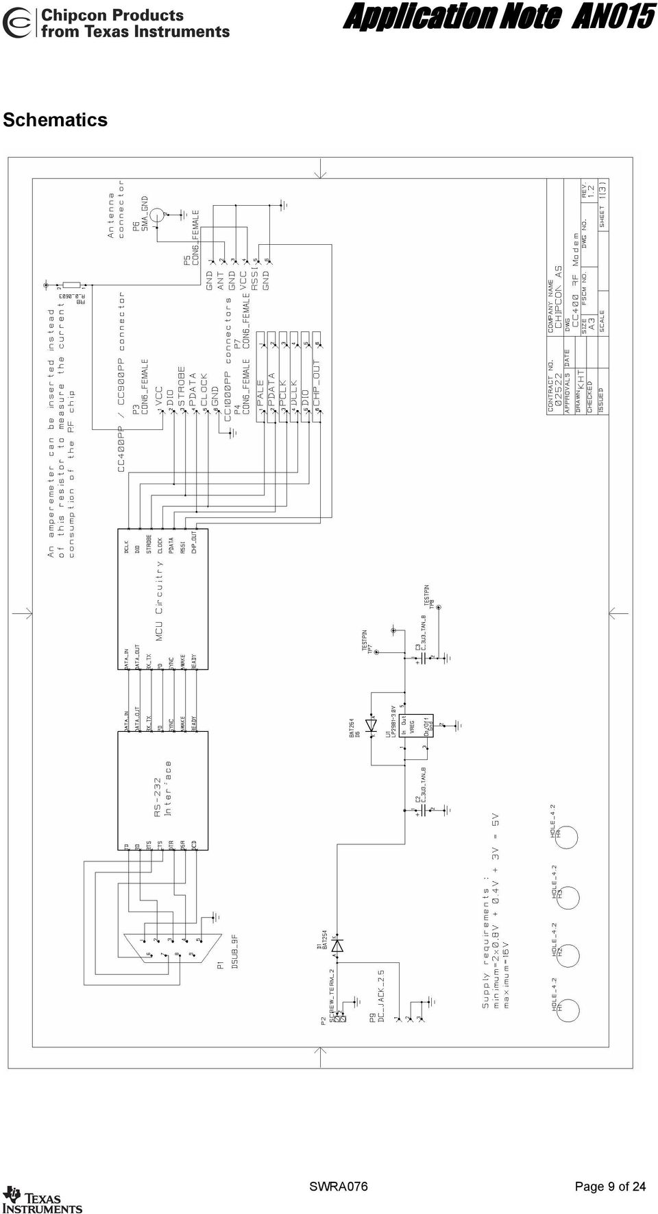
8 The following settings should be used in Microchip s MPLAB software when reprogramming the PIC: Oscillator: HS Watchdog: OFF Power-up timer: ON Brown-out detect: OFF Low-voltage program: OFF Code Protect Data EE: OFF Flash Memory Write: Memory written to by EECON Code protect Code protection OFF Erase all before program must be turned OFF Temperature sensor An analogue temperature sensor is located on the RF modem PCB right under the plug-andplay module. This temperature sensor is connected to an ADC input on the microcontroller, and can be used for compensating transceiver crystal drift due to temperature. Although the ideal placement for such a sensor would be right next to the transceiver crystal, this is not possible in this reference design, because the crystal is located on another PCB. Chipcon recommends that the sensor and the crystal be positioned as close to each other as possible in temperature compensation applications. See [4] for more information about the temperature sensor. The current version of the RF Modem software does not implement temperature drift compensation. SWRA076 Page 8 of 24

9 Schematics SWRA076 Page 9 of 24
10 SWRA076 Page 10 of 24

11 SWRA076 Page 11 of 24

12 Bill of materials Ref. Description Value Part C1 Capacitor nF C_100N_0603_X7R_K_50 C2 Capacitor, tantalium 3.3uF C_3U3_TAN_B C3 Capacitor, tantalium 3.3uF C_3U3_TAN_B C4 Capacitor nF C_100N_0603_X7R_K_50 C5 Capacitor nF C_100N_0603_X7R_K_50 C6 Capacitor nF C_100N_0603_X7R_K_50 C7 Capacitor nF C_100N_0603_X7R_K_50 C8 Capacitor nF C_100N_0603_X7R_K_50 C9 Capacitor nF C_100N_0603_X7R_K_50 C10 Capacitor nF C_100N_0603_X7R_K_50 C11 Capacitor nF C_100N_0603_X7R_K_50 C12 Capacitor nF C_100N_0603_X7R_K_50 C13 Capacitor nF C_100N_0603_X7R_K_50 C14 Capacitor nF C_100N_0603_X7R_K_50 C15 Capacitor pF C_15P_0603_NP0_G_50 C16 Capacitor pF C_15P_0603_NP0_G_50 D1 Diode, Si BAT254 D2 LED, green, SMD LED_CL150GCD D3 LED, red, SMD LED_CL150URCD D4 LED, yellow, SMD LED_CL150YCD D5 Diode, Si BAT254 D6 Diode, Si BAT254 H1 Circuit Board Support Distance 12.5mm H2 Circuit Board Support Distance 12.5mm H3 Circuit Board Support Distance 12.5mm H4 Circuit Board Support Distance 12.5mm P1 D-Sub, 9 pin, female DSUB_9F P2 2 pin terminal, screw SCREW_TERM_2 P3 Connector, 0.9 mm pin, female CON6_FEMALE P4 Connector, 0.9 mm pin, female CON6_FEMALE P5 Connector, 0.9 mm pin, female CON6_FEMALE P6 SMA connector, straight SMA P7 Connector, 0.9 mm pin, female CON6_FEMALE P8 6-pin modular jack MODULAR_CONN_6 P9 DC jack, 2.5mm center pin DC_JACK_2.5 R1 Resistor kΩ R_47K_0603_G R2 Resistor Ω R_470_0603_J R3 Resistor Ω R_470_0603_J R4 Resistor Ω R_470_0603_J R5 Resistor Ω R_0_0603 R8 Resistor Ω R_0_0603 S1 Push button, SMD PUSH_BUTTON S2 Push button, SMD PUSH_BUTTON S3 Push button, SMD PUSH_BUTTON TP1 Testpoint TESTPIN TP2 Testpoint TESTPIN TP3 Testpoint TESTPIN TP4 Testpoint TESTPIN TP5 Testpoint TESTPIN TP6 Testpoint TESTPIN SWRA076 Page 12 of 24

13 TP7 Testpoint TESTPIN TP8 Testpoint TESTPIN U1 National Semiconductor LP V LP V low drop-out regulator U2 Maxim RS-232 Transceiver, SO-16 MAX3232 U3 Maxim RS-232 Transceiver, SO-16 MAX3232 U4 Microchip PIC16LF876 microcontroller, PIC16LF876 SO-28 U5 National Semiconductor LM61 LM61 temperature sensor, SOT23 X MHz Crystal, 16pF load, HC-49- SMD X_10.000/50/30/10/16 SWRA076 Page 13 of 24

14 Software The software for the PIC microcontroller is written for the IAR PIC16 C-compiler. The highest priority task of the software is performed by the external interrupt handler, which is triggered by transitions in the DCLK clock coming from the CC1000. The main program handles state transitions, writes data in the RX buffer to the UART, reads any incoming data from the UART and stores it in the TX buffer, and handles the time-out and button debouncing timers. Configuration of the CC1000 is performed either using general I/O pins or the PIC s SPI interface. If the symbol SPI is defined, the SPI code is used; otherwise the slower general I/O pin-based code is used. For more details on CC1000 configuration issues, see Chipcon application note AN009. Resource usage Most of the microcontroller s SRAM data memory is used for buffering the incoming and outgoing data streams. When data arrives from the UART, the UART main program stores the data in the TX buffer, and an RF packet is sent only after a timeout or when the buffer is full. When data is received via RF, the data is buffered in the RX ring buffer, and sent to the PC via the UART. The EEPROM data memory is used for non-volatile storage of configuration parameters. These parameters may be changed by entering the configuration mode at start up. The required data is read from the EEPROM memory as needed. Packet protocol The protocol chosen for the RF modem is a simple variable-length packet protocol. Field Length Format, usage Preamble 32 bits Alternating 0s and 1s Start-of-Frame / 2 bytes 0x33CC for modem application Unique Identifier Unit address 1 byte 0 for broadcast, for unit address, not currently used Data length 1 byte Length of data payload Data Variable Data payload, maximum length is 64 bytes Table 4: Data protocol The maximum packet length for the RF modem software is 64 bytes. If the modem receives a packet a greater data length than this, the packet is discarded. SWRA076 Page 14 of 24

15 Source files The software consists of several source code files. A quick overview of the files is provided in the table below. File name rfmodem_cc1000.c modemhw.h cc1000.c cc1000.h configure.c configure.h getchar.c putchar.c simpleio.c simpleio.h interrupt.c main.h Short description Main program source file Header file defining the I/O pin usage Function library for configuring and using CC1000. See application note AN009 for more information. Header file for cc1000.c, also includes definitions for all the registers of the CC1000. Configuration menu source file Header file for configure.c Implements the C library function getchar() using the UART Implements the C library function putchar() using the UART Implements simple replacements for standard I/O functions like printf() and scanf(). Uses the getchar() and putchar() functions implemented in getchar.c and putchar.c Header file for simpleio.c Contains the RF modem interrupt handler Header file used by interrupt.c to gain access to variables shared with the main program Table 5: Summary of software source files All of these files can be downloaded from Chipcon s web site at All other files referenced are standard ANSI C library files and should be provided by the compiler vendor. Software implementation The software is implemented as a state machine with three different states. RESET IDLE TX Buffer full or timeout elapsed Valid preamble and SOF detected RX TX Finished receiving data or error detected Finshed sending data in buffer Figure 5: State diagram In the IDLE state, the modem looks for a valid incoming preamble and for data from the RS- 232 interface. If the RF modem detects a valid incoming preamble and it is followed by a valid SWRA076 Page 15 of 24

16 start-of-frame (SOF) word, the modem enters the RX state. If the transmit buffer is full or if the timeout period has expired since the last character was received from the RS-232 interface, the modem enters the TX state. In the RX state, header data is handled in the interrupt handler, data is buffered in a circular buffer and transmitted via the RS-232 interface in the main program. In the TX state, the data in the transmit buffer is sent to the CC1000 for transmission. State switching is performed by the main program; the interrupt routine updates a NextState variable when a state change is to occur. SWRA076 Page 16 of 24

17 Main program The figure below is a flowchart of the main program, implemented in the main() function in rfmodem.c. Power up Initialise PIC registers Initialise and calibrate CC1000 Button 2 pressed? Enter configuration mode Show startup message Loop forever Should state change occur? Change state Update state of averaging filter Data in RX circular buffer? Send data to UART UART received data? Store data in TX buffer Buffer full? Enter TX state Time-out timer triggered? Button debouncing timer triggered? Button pressed? Put character in buffer Enter TX state Figure 6: Main program flowchart SWRA076 Page 17 of 24

18 Interrupt handler The figure below is a flow chart of the interrupt handler, implemented in interrupt.c for interrupts generated by transitions on the DCLK pin of the CC1000. The processing that is done depends on the current state of the software. Interrupt triggered TX State? IDLE RX Write bit to CC1000 Read bit from CC1000 Read bit from CC1000 Sent entire packet? Finished with byte? Declared valid preamble? Finished with byte? Enter IDLE state SOF part 2? SOF correct? Received SOF? Enter RX mode Enter IDLE state Receiving valid preamble bits? Load next byte into shift register Packet size? Store value Declare error Write byte to RX circular buffer Enough valid preamble bits received? Finished with packet? Enter IDLE state Declare preamble found Return from interrupt Figure 7: Interrupt handler flow chart SWRA076 Page 18 of 24

19 Operation The diagrams below, generated from a logic analyzer, illustrate the operation of the RF Modem and show how the I/O lines behave during communication. The figure blow shows a packet consisting of a single ASCII a being received. Once a valid preamble is detected, the averaging filter is locked. The lock averaging filter command to the CC1000 can be seen to the left in this figure, appearing as a short transition in the PALE, PCLK and PDATA signals. The receiver then receives the first part of the SOF and, once this is accepted, it enters the RX state. The READY signal is set high (indicating to the PC that it will not accept serial data), and the RX LED is lit (active low). The header data is processed, indicating that this packet contains only one byte of payload data. This data byte is stored in the receive ring-buffer. As soon as the last bit of the message is received, the averaging filter is unlocked (the second transition of the PALE, PCLK and PDATA signals). Packet reception is then complete. The ring buffer is processed when sufficient time is available and the data is sent to the UART (signal on DATA_OUT line). Figure 8: I/O lines during reception of a short packet SWRA076 Page 19 of 24

20 The figure below shows the CC1000 being configured by using the SPI interface of the microcontroller. The configuration is very fast; programming a register takes 9 us. The SPI interface is configured for reading data on the falling edge of the clock and the clock idle state is set to HIGH to communicate with the CC1000. As the transmit and receive lines of the SPI interface are connected together to form a two-wire interface, the SPI output is set to be an input when reading data from the CC1000. Figure 9: I/O lines during CC1000 configuration SWRA076 Page 20 of 24

21 Figure 10 shows a long string of ASCII characters being received ( abcdefghijklmnopqrstuvwxyzABCDEFGHIJKLMNOPQRSTUVWXYZ ). This string is 62 characters long, and therefore split into two packets. In between the two packets is also a rejected packet, the RF Modem goes into the RX state, but the second half of the SOF is not correct, and the modem returns to the IDLE state. Figure 10: I/O lines during reception of long packets SWRA076 Page 21 of 24
22 The figure below is an enlargement of the middle of the transmission shown in Figure 10. The time between UART transmissions is 670us. Figure 11: Close-up of middle of long packet Performance The C-code presented in this application note works for data rates up to 19.2kbit/s. At rates faster than this, the interrupt routine does not execute fast enough to keep up with the data flow. For a data rate of 38.4kbit/s, the PIC16 microcontroller has only time to execute 65 instructions for each bit. The machine code created by the compiler is not fast enough to do this, but a handwritten interrupt routine in assembly can be able to execute fast enough. Due to time by the microcontroller during mode switching, packet loss is higher at 19.2kbit/s than at the lower data rates. Implementing an optimized interrupt handler in assembly is left as an exercise for the reader. Operation at 76.8kbit/s is not possible with the current design, as this leaves only 32 instructions for each bit too few to implement the functionality needed. While the CC1000 has no problems operating at a data rate of 76.8 kbit/s, the microcontroller does. There are two ways to reach this data rate; either use a faster microcontroller or a byte-oriented serial interface to handle the data interface. The PIC16F876 has a maximum clock rate of 10 MHz when run on a 3.0V supply voltage. It processes instructions at one-fourth this rate, executing 2.5 million instructions per second (MIPS). Preliminary information from Microchip indicates that the PIC18F242 may be a viable alternative. The PIC18 is pin-compatible, and can run at 20 MHz (5 MIPS) at 3.0V. The SWRA076 Page 22 of 24
23 instruction set is also more efficient, so the PIC18 should be able to handle a 76.8kbit/s data rate. Because the instruction set is different, the source code would have to be ported to IAR s PIC18 compiler. Several other available microcontrollers run at speeds of up to 1MIPS/MHz clock. For instance the new megaavr microcontrollers from Atmel can run at up to 8 MHz with a 3.0V supply voltage, giving a performance of 8 MIPS. This makes operation with very high data rates possible. Another way of increasing the maximum data rate is to use a byte-oriented serial port to interface with the CC1000. A USART or an SPI interface can be used. This has not been done in this reference design because the USART is used for RS-232 interface and the SPI interface is used for CC1000 configuration. In a design that does not need an RS-232 interface, the USART can be connected to the data interface of the CC1000 instead. This will decrease the microcontroller s processing-load by a factor of almost 8. Byte synchronization will have to be handled by looking for the end of the SOF, and then starting USART reception at the correct time. Modifications The RF modem software can be modified for different applications: For low-power use, the RF modem software can be modified so that the receiver polls regularly instead of being on all the time. If this is implemented, the preamble should be lengthened so that it lasts longer than the polling period. Support for repeaters can be quite easily added by implementing a hop counter. For adding error correction and/or detection, an ACK/NAK handshake protocol can be added, together with CRC checking. Some form of forward error correction (FEC) can be beneficial. Temperature compensation of the reference crystal may be added for applications where very good frequency accuracy is important. Source code and PCB documentation The PCB docuemtnation files (including Gerber-format files for PCB production) and full source code for the RF modem software can be downloaded from Chipcon s web site at SWRA076 Page 23 of 24
24 References [1] CC1000PP Plug-and-play reference design, Chipcon 2002 [2] MPLAB ICD User s Guide, Microchip Technology Inc [3] Microchip PIC16F87X Data Sheet, Microchip Technology Inc [4] LM61 2.7V, SOT-23 or TO-92 Temperature Sensor Data Sheet, National Semiconductor Corporation 2001 Contact Information Chipcon is a world-wide supplier of RFICs. For further information on the products from Chipcon please contact us or visit our web site. An updated list of distributors is also available at our web site. Chipcon AS Gaustadalléen 21 N-0349 Oslo, NORWAY Telephone : (+47) Telefax : (+47) [email protected] Web site : Disclaimer Chipcon AS believes the furnished information is correct and accurate at the time of this printing. However, Chipcon AS reserves the right to make changes to this application note and the product(s) it describes without notice. Chipcon AS assumes no responsibility for the use of the described information. Information and product updates as well as the most recent news are available at Chipcon s web site. SmartRF is a registered trademark of Chipcon AS. All other trademarks or registered trademarks are the sole property of their respective owners. SWRA076 Page 24 of 24
RC2200DK Demonstration Kit User Manual
 Demonstration Kit User Manual Table of contents TABLE OF CONTENTS... 1 QUICK INTRODUCTION... 2 INTRODUCTION... 3 DEMONSTRATION BOARD... 4 POWER SUPPLY SECTION... 5 RS-232 INTERFACE... 6 CONNECTORS... 7
Using Xbee 802.15.4 in Serial Communication
 Using Xbee 802.15.4 in Serial Communication Jason Grimes April 2, 2010 Abstract Instances where wireless serial communication is required to connect devices, Xbee RF modules are effective in linking Universal
Date Rev. Details Author
 Jtech engineering ltd J - Te c h E n g i n e e ring, L t d. 11080 Bond Boulevard Delta BC V4E 1M7 Canada Tel: 604 543 6272 Fax: 604 543 6476 http://www.jtecheng.com AUTODIALER USER S MANUAL REVISION HISTORY
Single channel data transceiver module WIZ2-434
 Single channel data transceiver module WIZ2-434 Available models: WIZ2-434-RS: data input by RS232 (±12V) logic, 9-15V supply WIZ2-434-RSB: same as above, but in a plastic shell. The WIZ2-434-x modules
ET-BASE AVR ATmega64/128
 ET-BASE AVR ATmega64/128 ET-BASE AVR ATmega64/128 which is a Board Microcontroller AVR family from ATMEL uses MCU No.ATmega64 and ATmega128 64PIN. Board ET-BASE AVR ATmega64/128 uses MCU s resources on
Develop a Dallas 1-Wire Master Using the Z8F1680 Series of MCUs
 Develop a Dallas 1-Wire Master Using the Z8F1680 Series of MCUs AN033101-0412 Abstract This describes how to interface the Dallas 1-Wire bus with Zilog s Z8F1680 Series of MCUs as master devices. The Z8F0880,
SKP16C62P Tutorial 1 Software Development Process using HEW. Renesas Technology America Inc.
 SKP16C62P Tutorial 1 Software Development Process using HEW Renesas Technology America Inc. 1 Overview The following tutorial is a brief introduction on how to develop and debug programs using HEW (Highperformance
Elettronica dei Sistemi Digitali Costantino Giaconia SERIAL I/O COMMON PROTOCOLS
 SERIAL I/O COMMON PROTOCOLS RS-232 Fundamentals What is RS-232 RS-232 is a popular communications interface for connecting modems and data acquisition devices (i.e. GPS receivers, electronic balances,
What is Easy-Radio? Devices Covered. Frequency Hopping Transceiver. Where x00 denotes frequency of operation. E.g. 400 = 433MHz
 What is Easy-Radio? Easy-Radio modules combine low power radio transmitters, receivers or transceivers with on-board microcontrollers to produce intelligent RF modules that provide simple to use wireless
RN-WIFLY-EVAL-UM. WiFly Evaluation Kit. 2012 Roving Networks. All rights reserved. RN-WIFLY-EVAL-UM Version 1.32r 10/9/2012 USER MANUAL
 WiFly Evaluation Kit 2012 Roving Networks. All rights reserved. Version 1.32r 10/9/2012 USER MANUAL OVERVIEW This document describes the hardware and software setup for Roving Networks evaluation kits,
EasyPIC4 User s Manual
 SOFTWARE AND HARDWARE SOLUTIONS FOR THE EMBEDDED WORLD MikroElektronika - Books - Compilers User s Manual PIC MICROCHIP DEVELOPMENT BOARD 3in1 mikro IN-CIRCUIT DEBUGGER USB 2.0 IN-CIRCUIT PROGRAMMER With
The Programming Interface
 : In-System Programming Features Program any AVR MCU In-System Reprogram both data Flash and parameter EEPROM memories Eliminate sockets Simple -wire SPI programming interface Introduction In-System programming
Tutorial for MPLAB Starter Kit for PIC18F
 Tutorial for MPLAB Starter Kit for PIC18F 2006 Microchip Technology Incorporated. All Rights Reserved. WebSeminar Title Slide 1 Welcome to the tutorial for the MPLAB Starter Kit for PIC18F. My name is
Quick Start Guide. MRB-KW01 Development Platform Radio Utility Application Demo MODULAR REFERENCE BOARD
 Quick Start Guide MRB-KW01 Development Platform Radio Utility Application Demo MODULAR REFERENCE BOARD Quick Start Guide Get to Know the MRB-KW01x Module UART Selector ANT 1 RFIO (TX/RX) USB 2.0 Serial
Programming and Using the Courier V.Everything Modem for Remote Operation of DDF6000
 Programming and Using the Courier V.Everything Modem for Remote Operation of DDF6000 1.0 Introduction A Technical Application Note from Doppler System July 5, 1999 Version 3.x of the DDF6000, running version
An Introduction to MPLAB Integrated Development Environment
 An Introduction to MPLAB Integrated Development Environment 2004 Microchip Technology Incorporated An introduction to MPLAB Integrated Development Environment Slide 1 This seminar is an introduction to
Fondamenti su strumenti di sviluppo per microcontrollori PIC
 Fondamenti su strumenti di sviluppo per microcontrollori PIC MPSIM ICE 2000 ICD 2 REAL ICE PICSTART Ad uso interno del corso Elettronica e Telecomunicazioni 1 2 MPLAB SIM /1 MPLAB SIM is a discrete-event
Accurate Measurement of the Mains Electricity Frequency
 Accurate Measurement of the Mains Electricity Frequency Dogan Ibrahim Near East University, Faculty of Engineering, Lefkosa, TRNC [email protected] Abstract The frequency of the mains electricity supply
STK500... User Guide
 STK500... User Guide Table of Contents Section 1 Introduction... 1-1 1.1 Starter Kit Features...1-1 1.2 Device Support...1-2 Section 2 Getting Started... 2-1 2.1 Unpacking the System...2-1 2.2 System
RN-XV-RD2 Evaluation Board
 RN-XV-RD2 Evaluation Board 2012 Roving Networks. All rights reserved. -1.01Version 1.0 9/28/2012 USER MANUAL OVERVIEW This document describes the hardware and software setup for Roving Networks RN-XV-RD2
RN-131-PICTAIL & RN-171-PICTAIL Evaluation Boards
 RN-131-PICTAIL & RN-171-PICTAIL Evaluation Boards 2012 Roving Networks. All rights reserved. Version 1.0 9/7/2012 USER MANUAL OVERVIEW The RN-131 and RN-171 WiFly radio modules are complete, standalone
Serial Communications
 April 2014 7 Serial Communications Objectives - To be familiar with the USART (RS-232) protocol. - To be able to transfer data from PIC-PC, PC-PIC and PIC-PIC. - To test serial communications with virtual
Lab Experiment 1: The LPC 2148 Education Board
 Lab Experiment 1: The LPC 2148 Education Board 1 Introduction The aim of this course ECE 425L is to help you understand and utilize the functionalities of ARM7TDMI LPC2148 microcontroller. To do that,
Software User Guide UG-461
 Software User Guide UG-461 One Technology Way P.O. Box 9106 Norwood, MA 02062-9106, U.S.A. Tel: 781.329.4700 Fax: 781.461.3113 www.analog.com ezlinx icoupler Isolated Interface Development Environment
PICmicro tm Development Board
 PICmicro tm Development Board Crownhill Associates smart electronic solutions Disclaimer In order to comply with EMC directive 89/336/EEC, this product should not be used outside of a classroom or laboratory
Advanced Data Capture and Control Systems
 Advanced Data Capture and Control Systems Tronisoft Limited Email: [email protected] Web: www.tronisoft.com RS232 To 3.3V TTL User Guide RS232 to 3.3V TTL Signal Converter Modules P/N: 9651 Document
MFRD52x. Mifare Contactless Smart Card Reader Reference Design. Document information
 Rev. 2.1 17. April 2007 Preliminary Data Sheet Document information Info Keywords Content MFRC522, MFRC523, MFRC52x, MFRD522, MFRD523, Mifare Contactless Smart Card Reader Reference Design, Mifare Reader
SPI. Overview and Use of the PICmicro Serial Peripheral Interface. Getting Started: SPI
 SPI Overview and Use of the PICmicro Serial Peripheral Interface In this presentation, we will look at what the Serial Peripheral Interface, otherwise known as the SPI, is, and how it is used to communicate
RS-232 COMMUNICATIONS
 Technical Note D64 0815 RS-232 COMMUNICATIONS RS-232 is an Electronics Industries Association (EIA) standard designed to aid in connecting equipment together for serial communications. The standard specifies
Dial-Up / Leased-Line Modem. User Manual. AGM Electronics, Inc Dial-Up / Leased-Line Modem, Series ( ) 5019-1 Manual Rev A + - DLM CTS RTS DTR DSR
 5019-1 Manual Rev A + - DLM CTS RTS DTR DSR") AGM Electronics, Inc Dial-Up / Leased-Line Modem, Series ( ) 5019-1 Manual Rev A User Manual + - CD CTS RTS DTR. DSR RI RX TX PHONE LINE DLM Dial-Up / Leased-Line Modem Dial-Up / Leased-Line Modem CONTENTS
AGM Electronics, Inc Dial-Up / Leased-Line Modem, Series ( ) 5019-1 Manual Rev A User Manual + - CD CTS RTS DTR. DSR RI RX TX PHONE LINE DLM Dial-Up / Leased-Line Modem Dial-Up / Leased-Line Modem CONTENTS
The modular concept of the MPA-3 system is designed to enable easy accommodation to a huge variety of experimental requirements.
 HARDWARE DESCRIPTION The modular concept of the MPA-3 system is designed to enable easy accommodation to a huge variety of experimental requirements. BASE MODULE GO LINE Digital I/O 8 Analog Out AUX 1
Data sheet Wireless UART firmware version 4.02
 Data sheet Wireless UART firmware version 4.02 BLUETOOTH is a trademark owned by Bluetooth SIG, Inc., U.S.A. and licensed to Free2move Rev: 22 December 2008 Table of contents 1 GENERAL INFORMATION...4
USB / Data-Acquisition Module NOW LEAD-FREE
 USB / Data-Acquisition Module NOW LEAD-FREE DLP-TEMP-G Features: Digital I/Os, Analog Inputs (0- Volts) or any combination USB. and.0 Compatible Interface th Generation Silicon from FTDI Supports Up To
PolyBot Board. User's Guide V1.11 9/20/08
 PolyBot Board User's Guide V1.11 9/20/08 PolyBot Board v1.1 16 pin LCD connector 4-pin SPI port (can be used as digital I/O) 10 Analog inputs +5V GND GND JP_PWR 3-pin logic power jumper (short top 2 pins
MCB3101 (Class I) WiRobot Serial Bluetooth Wireless Module User Manual
 WiRobot Serial Bluetooth Wireless Module User Manual") MCB3101 (Class I) WiRobot Serial Bluetooth Wireless Module User Manual Version: 1.0.1 Dec. 2005 Table of Contents I. Introduction 2 II. Operations 2 II.1. Theory of Operation 2 II.2. Configuration (PC-PC
MCB3101 (Class I) WiRobot Serial Bluetooth Wireless Module User Manual Version: 1.0.1 Dec. 2005 Table of Contents I. Introduction 2 II. Operations 2 II.1. Theory of Operation 2 II.2. Configuration (PC-PC
KTA-223 Arduino Compatible Relay Controller
 8 Relay Outputs 5A 250VAC 4 Opto-Isolated Inputs 5-30VDC 3 Analog Inputs (10 bit) Connections via Pluggable Screw Terminals 0-5V or 0-20mA Analog Inputs, Jumper Selectable 5A Relay Switching Power Indicator
ARM Thumb Microcontrollers. Application Note. Software ISO 7816 I/O Line Implementation. Features. Introduction
 Software ISO 7816 I/O Line Implementation Features ISO 7816-3 compliant (direct convention) Byte reception and transmission with parity check Retransmission on error detection Automatic reception at the
Wireless Temperature
 Wireless Temperature connected freedom and Humidity Sensor Using TELRAN Application note TZ1053AN-06 Oct 2011 Abstract Dr. C. Uche This application note describes the complete system design (hardware and
PICAXE RF CONNECT KIT (AXE213)
") PICAXE RF CONNECT KIT (AXE213) Kit Contents: PCB AXE213 Transmitter & Receiver PCB Pair R1-3 10k resistor (brown black orange gold) R4-5 470 resistor (yellow violet brown gold) R6 22k resistor (red red
PICAXE RF CONNECT KIT (AXE213) Kit Contents: PCB AXE213 Transmitter & Receiver PCB Pair R1-3 10k resistor (brown black orange gold) R4-5 470 resistor (yellow violet brown gold) R6 22k resistor (red red
M68EVB908QL4 Development Board for Motorola MC68HC908QL4
 M68EVB908QL4 Development Board for Motorola MC68HC908QL4! Axiom Manufacturing 2813 Industrial Lane Garland, TX 75041 Email: [email protected] Web: http://www.axman.com! CONTENTS CAUTIONARY NOTES...3 TERMINOLOGY...3
LOW COST GSM MODEM. Description. Part Number
 Dual Band 900 / 1800 MHz Fax, SMS and Data Integral SIM Card holder Siemens TC-35i GSM Engine Rugged Extruded Aluminium Enclosure Compact Form Factor 86 x 54 x 25mm RS232 Interface with Auto baud rate
Web Site: www.parallax.com Forums: forums.parallax.com Sales: [email protected] Technical: [email protected]
 Web Site: www.parallax.com Forums: forums.parallax.com Sales: [email protected] Technical: [email protected] Office: (916) 624-8333 Fax: (916) 624-8003 Sales: (888) 512-1024 Tech Support: (888) 997-8267
How To Program A Microcontroller Board (Eb064) With A Psp Microcontroller (B064-74) With An Ios 2.5V (Power) And A Ppt (Power Control) (Power Supply) (
 With A Psp Microcontroller (B064-74) With An Ios 2.5V (Power) And A Ppt (Power Control) (Power Supply) (") dspic / PIC24 Multiprogrammer datasheet EB064-00 00-1 Contents 1. About this document... 2 2. General information... 3 3. Board layout... 4 4. Testing this product... 5 5. Circuit description... 6 Appendix
dspic / PIC24 Multiprogrammer datasheet EB064-00 00-1 Contents 1. About this document... 2 2. General information... 3 3. Board layout... 4 4. Testing this product... 5 5. Circuit description... 6 Appendix
RN-131-PICTAIL & RN-171-PICTAIL Web-Server Demo Application
 RN-131-PICTAIL & RN-171-PICTAIL Web-Server Demo Application 2012 Roving Networks. All rights reserved. RN-131/171-PICTAIL-UM Version 1.0 1/8/2013 OVERVIEW The RN-131 and RN-171 WiFly radio modules are
1.1 Connection. 1.1.1 Direct COM port connection. 1. Half duplex RS232 spy cable without handshaking
 POS function Marchen POS-DVR surveillance system is a professional surveillance integrated with POS system. By bringing video and POS transaction data together, the POS-DVR surveillance system provides
MX PIC24F Educational Module User Manual
 MX PIC24F Educational Module User Manual Revision History Date Description Initial release. Table of Contents 1. Introduction... 3 1.1. Package Contents... 3 1.2. Key Hardware Features... 4 2. Hardware
Secure My-d TM and Mifare TM RFID reader system by using a security access module Erich Englbrecht ([email protected]) V0.1draft
 V0.1draft") Application Report Secure My-d TM and Mifare TM RFID reader system by using a security access module Erich Englbrecht ([email protected]) V0.1draft Embedded RF ABSTRACT This application report describes
Application Report Secure My-d TM and Mifare TM RFID reader system by using a security access module Erich Englbrecht ([email protected]) V0.1draft Embedded RF ABSTRACT This application report describes
PICNet 1. PICNet 1 PIC18 Network & SD/MMC Development Board. Features. Applications. Description
 Features PICNet 1 PIC18 Network & SD/MMC Development Board IC Sockets for 28 or 40-pin Microchip PIC18F Microcontrollers IC Socket for 8-pin serial EEPROM Multiple MCU Oscillator sources Full 10BaseT IEEE
User Manual IC-485AI 2002-09-27
 User Manual IC-485AI Note: This equipment has been tested and found to comply ith the limits for a Class A digital device pursuant to Part 15 of the FCC Rules. These limits are designed to provide reasonable
Technical description MX-1 VB Edge
 1 (7) Technical description MX-1 VB Edge 2 (7) Table of Contents 1 General description...3 2 Connectors...4 3 ON/OFF operation...5 4 Power...5 5 LED indicators...6 6 Enclosure...6 7 Mounting...6 8 and
TURBO PROGRAMMER USB, MMC, SIM DEVELOPMENT KIT
 TURBO PROGRAMMER USB, MMC, SIM DEVELOPMENT KIT HARDWARE GUIDE This document is part of Turbo Programmer documentation. For Developer Documentation, Applications and Examples, see http:/// PRELIMINARY (C)
Quectel Cellular Engine
 Cellular Engine GSM UART Port Application Notes GSM_UART_AN_V1.01 Document Title GSM UART Port Application Notes Version 1.01 Date 2009-11-16 Status Document Control ID Release GSM_UART_AN_V1.01 General
Chapter 13. PIC Family Microcontroller
 Chapter 13 PIC Family Microcontroller Lesson 01 PIC Characteristics and Examples PIC microcontroller characteristics Power-on reset Brown out reset Simplified instruction set High speed execution Up to
RS232 Board datasheet
 RS232 Board datasheet Contents 1. About this document 2. General information 3. Board Layout 4. Getting Started 5. Circuit Description Appendix 1 Circuit Diagram Copyright 2004 Matrix Multimedia Limited
Bluetooth to Serial Adapter
 Bluetooth to Serial Adapter Third Edition, Oct 2007 Version 3.0 771-BTS1009C3-001 Contents 1.0 Features....P.2 2.0 Package Content....P.2 3.0 Hard Drives Requirement.P.2 4.0 Specifications.P.3 5.0 Pin
Tire pressure monitoring
 Application Note AN601 Tire pressure monitoring 1 Purpose This document is intended to give hints on how to use the Intersema pressure sensors in a low cost tire pressure monitoring system (TPMS). 2 Introduction
Implementing SPI Master and Slave Functionality Using the Z8 Encore! F083A
 Application Note Implementing SPI Master and Slave Functionality Using the Z8 Encore! F083A AN026701-0308 Abstract This application note demonstrates a method of implementing the Serial Peripheral Interface
USBSPYDER08 Discovery Kit for Freescale MC9RS08KA, MC9S08QD and MC9S08QG Microcontrollers User s Manual
 USBSPYDER08 Discovery Kit for Freescale MC9RS08KA, MC9S08QD and MC9S08QG Microcontrollers User s Manual Copyright 2007 SofTec Microsystems DC01197 We want your feedback! SofTec Microsystems is always on
Real Time Clock USB Evaluation Board V3.0
 Real Time Clock USB Evaluation Board V.0 Application Note February 9, 008 RTC EVB Intersil RTC Devices Supported Introduction This evaluation board provides a platform for testing Intersil Real Time Clock
Modbus Communications for PanelView Terminals
 User Guide Modbus Communications for PanelView Terminals Introduction This document describes how to connect and configure communications for the Modbus versions of the PanelView terminals. This document
T3 Mux M13 Multiplexer
 T3 Mux M13 Multiplexer User Manual [Type the abstract of the document here. The abstract is typically a short summary of the contents of the document. Type the abstract of the document here. The abstract
A RF18 Remote control receiver MODULE
 A RF18 Remote control receiver MODULE User Guide No part of this document may be reproduced or transmitted (in electronic or paper version, photocopy) without Adeunis RF consent. This document is subject
ABACOM - netpio. http://www.abacom-online.de/div/setup_netpio.exe
 ABACOM - netpio Download http://www.abacom-online.de/div/setup_netpio.exe The ABACOM netpio board is a 10Mbit network interface designed for measurement and control applications. The board is available
Hello, and welcome to this presentation of the STM32L4 reset and clock controller.
 Hello, and welcome to this presentation of the STM32L4 reset and clock controller. 1 The STM32L4 reset and clock controller manages system and peripheral clocks. STM32L4 devices embed three internal oscillators,
Chapter 4 T1 Interface Card
 Chapter 4 T1 Interface Card GENERAL This chapter describes DTE interface options that may be required if application requirements change. It also describes software configuration for the T1 interface card.
Serial Communications
 Serial Communications 1 Serial Communication Introduction Serial communication buses Asynchronous and synchronous communication UART block diagram UART clock requirements Programming the UARTs Operation
Microcontroller Based Low Cost Portable PC Mouse and Keyboard Tester
 Leonardo Journal of Sciences ISSN 1583-0233 Issue 20, January-June 2012 p. 31-36 Microcontroller Based Low Cost Portable PC Mouse and Keyboard Tester Ganesh Sunil NHIVEKAR *, and Ravidra Ramchandra MUDHOLKAR
AN3265 Application note
 Application note Handling hardware and software failures with the STM8S-DISCOVERY Application overview This application is based on the STM8S-DISCOVERY. It demonstrates how to use the STM8S window watchdog
Web Site: www.parallax.com Forums: forums.parallax.com Sales: [email protected] Technical: [email protected]
 Web Site: www.parallax.com Forums: forums.parallax.com Sales: [email protected] Technical: [email protected] Office: (916) 624-8333 Fax: (916) 624-8003 Sales: (888) 512-1024 Tech Support: (888) 997-8267
FLYPORT Wi-Fi 802.11G
 FLYPORT Wi-Fi 802.11G System on module 802.11g WIFI - Infrastructure mode - softap mode - Ad hoc mode Microchip PIC 24F 16 bit processor Microchip MRF24WG0MA/MB - Native WiFi 802.11g transceiver - PCB
SUDT AccessPort TM Advanced Terminal / Monitor / Debugger Version 1.37 User Manual
 SUDT AccessPort TM Advanced Terminal / Monitor / Debugger Version 1.37 User Manual Version 1.0 - January 20, 2015 CHANGE HISTORY Version Date Description of Changes 1.0 January 20, 2015 Initial Publication
2.0 Command and Data Handling Subsystem
 2.0 Command and Data Handling Subsystem The Command and Data Handling Subsystem is the brain of the whole autonomous CubeSat. The C&DH system consists of an Onboard Computer, OBC, which controls the operation
IPG/7700 Hardware Manual SYSTECH. Document number 80-001099-7 Revision A
 IPG/7700 Hardware Manual SYSTECH C O R P O R A T I O N Document number 80-001099-7 Revision A Created 2010, and Protected Under the U.S. Copyright Act of 1976. Copyright 2010, SYSTECH Corporation All Rights
Designing VM2 Application Boards
 Designing VM2 Application Boards This document lists some things to consider when designing a custom application board for the VM2 embedded controller. It is intended to complement the VM2 Datasheet. A
Using the HCS12 Serial Monitor on Wytec Dragon-12 boards. Using Motorola s HCS12 Serial Monitor on Wytec s Dragon-12 boards
 Using Motorola s HCS12 Serial Monitor on Wytec s Dragon-12 boards Wytec s Dragon-12 development boards are pre-installed with DBug-12, a small monitor program which allows a user to interact with the board
Microtronics technologies Mobile: 99707 90092
 For more Project details visit: http://www.projectsof8051.com/rfid-based-attendance-management-system/ Code Project Title 1500 RFid Based Attendance System Synopsis for RFid Based Attendance System 1.
EZmoto V2. Product description Rev. 6 10/01/2014. EZmoto V2 Product description Rev.6 10/01/2014
 EZmoto V2 Product description Rev. 6 10/01/2014 1 Contents 1. Overview... 3 2. Hardware Interface Description... 3 2.1 Main features of the EZmoto... 3 2.2 Hardware block diagram... 4 2.3 Internal Hardware
LDG Electronics External Meter Serial Communications Protocol Specification
 M1000 METER PROTOCOL SPECIFICATION MANUAL REV A LDG Electronics External Meter Serial Communications Protocol Specification LDG Electronics 1445 Parran Road St. Leonard MD 20685-2903 USA Phone: 410-586-2177
Display Message on Notice Board using GSM
 Advance in Electronic and Electric Engineering. ISSN 2231-1297, Volume 3, Number 7 (2013), pp. 827-832 Research India Publications http://www.ripublication.com/aeee.htm Display Message on Notice Board
Part Number Description Packages available
 Features 3 digital I/O Serial Data output Connects directly to RF Modules Easy Enc / Dec Pairing Function Minimal External Components Required Performs all encoding/decoding of data for Reliable Operation.
Wireless monitoring system for temperature and humidity based on ZigBee
 Wireless monitoring system for temperature and humidity based on ZigBee Abstract Jianjun Chen* Shaoxing University uanpei College, Shaoxing, Zhejiang, 3000, China Received March 04, www.cmnt.lv Traditional
Bluetooth Serial Adapter
 RN-BT-SRL-UM Bluetooth Serial Adapter 0 Roving Networks. All rights reserved. RN-BT-SRL-UM-.0 Version.0 //0 USER MANUAL RN-BT-SRL-UM-.0 OVERVIEW Roving Networks offers a variety of Bluetooth serial adapters
Programming Flash Microcontrollers through the Controller Area Network (CAN) Interface
 Interface") Programming Flash Microcontrollers through the Controller Area Network (CAN) Interface Application te Programming Flash Microcontrollers through the Controller Area Network (CAN) Interface Abstract This
Programming Flash Microcontrollers through the Controller Area Network (CAN) Interface Application te Programming Flash Microcontrollers through the Controller Area Network (CAN) Interface Abstract This
MDM192 MULTI-DROPS DIGITAL MODEM FOR PRIVATE LINE. USER GUIDE Document reference : 9010709-03
 MDM192 MULTI-DROPS DIGITAL MODEM FOR PRIVATE LINE USER GUIDE Document reference : 9010709-03 If you have questions about the MDM192 or desire assistance, contact ETIC TELECOMMUNICATIONS at the following
PM1122 INT DIGITAL INTERFACE REMOTE
 PM1122 INT DIGITAL INTERFACE REMOTE PM1122 INT front panel description: 1. Clear wireless remotes knob: push this button for more than 2 seconds to clear the list of all assigned wireless remote settings
BIT COMMANDER. Serial RS232 / RS485 to Ethernet Converter
 BIT COMMANDER Serial RS232 / RS485 to Ethernet Converter (Part US2000A) Copyrights U.S. Converters 1 Contents Overview and Features... 3 Functions..5 TCP Server Mode... 5 Httpd Client Mode.5 TCP Auto mode....6
The $25 Son of a cheap timer This is not suitable for a beginner. You must have soldering skills in order to build this kit.
 The $25 Son of a cheap timer This is not suitable for a beginner. You must have soldering skills in order to build this kit. Micro Wizard has been manufacturing Pinewood Derby timers for over 10 years.
WIZ-Embedded WebServer User s Manual (Ver. 1.0)
") [텍스트 입력] WIZ-Embedded WebServer User s Manual (Ver. 1.0) 2007 WIZnet Inc. All Rights Reserved. For more information, visit our website at www.wiznet.co.kr Document History Information Revision Data Description
[텍스트 입력] WIZ-Embedded WebServer User s Manual (Ver. 1.0) 2007 WIZnet Inc. All Rights Reserved. For more information, visit our website at www.wiznet.co.kr Document History Information Revision Data Description
Design and Implementation of Home Monitoring System Using RF Technology
 International Journal of Advances in Electrical and Electronics Engineering 59 Available online at www.ijaeee.com & www.sestindia.org/volume-ijaeee/ ISSN: 2319-1112 Design and Implementation of Home Monitoring
DESIGN OF SMS ENABLED CAR SECURITY SYSTEM
 DESIGN OF SMS ENABLED CAR SECURITY SYSTEM K. A. Amusa Federal University of Agriculture, Abeokuta, O. O. Nuga Federal University of Agriculture, Abeokuta, A. A. Adetomi Federal University of Agriculture,
USER GUIDE EDBG. Description
 USER GUIDE EDBG Description The Atmel Embedded Debugger (EDBG) is an onboard debugger for integration into development kits with Atmel MCUs. In addition to programming and debugging support through Atmel
USB to serial chip CH340
 The DataSheet of CH340 (the first) 1 1. Introduction USB to serial chip CH340 English DataSheet Version: 1D http://wch.cn CH340 is a USB bus convert chip and it can realize USB convert to serial interface,
Keep it Simple Timing
 Keep it Simple Timing Support... 1 Introduction... 2 Turn On and Go... 3 Start Clock for Orienteering... 3 Pre Start Clock for Orienteering... 3 Real Time / Finish Clock... 3 Timer Clock... 4 Configuring
Bluetooth HC-06 with serial port module Easy guide
 1 Bluetooth HC-06 with serial port module Easy guide This manual consists of 3 parts: PART 1. Overview of Bluetooth HC-06 module with serial port. PART 2. Installing Bluetooth HC-06 module with Bolt 18F2550
LoRa FAQs. www.semtech.com 1 of 4 Semtech. Semtech Corporation LoRa FAQ
 LoRa FAQs 1.) What is LoRa Modulation? LoRa (Long Range) is a modulation technique that provides significantly longer range than competing technologies. The modulation is based on spread-spectrum techniques
EVAL-UFDC-1/UFDC-1M-16
 Evaluation Board for Universal Frequency-to- Digital Converters UFDC-1 and UFDC-1M-16 EVAL-UFDC-1/UFDC-1M-16 FEATURES Full-Featured Evaluation Board for the Universal Frequency-to-Digital Converters UFDC-1
The Analyst RS422/RS232 Tester. With. VTR, Monitor, and Data Logging Option (LOG2) User Manual
 User Manual") 12843 Foothill Blvd., Suite D Sylmar, CA 91342 818 898 3380 voice 818 898 3360 fax www.dnfcontrolscom The Analyst RS422/RS232 Tester With VTR, Monitor, and Data Logging Option (LOG2) User Manual Manual
12843 Foothill Blvd., Suite D Sylmar, CA 91342 818 898 3380 voice 818 898 3360 fax www.dnfcontrolscom The Analyst RS422/RS232 Tester With VTR, Monitor, and Data Logging Option (LOG2) User Manual Manual
Ocean Controls RC Servo Motor Controller
 Ocean Controls RC Servo Motor Controller RC Servo Motors: RC Servo motors are used in radio-controlled model cars and planes, robotics, special effects, test equipment and industrial automation. At the
HANDLING SUSPEND MODE ON A USB MOUSE
 APPLICATION NOTE HANDLING SUSPEND MODE ON A USB MOUSE by Microcontroller Division Application Team INTRODUCTION All USB devices must support Suspend mode. Suspend mode enables the devices to enter low-power
Data Cables. Schmitt TTL LABORATORY ELECTRONICS II
 Data Cables Data cables link one instrument to another. Signals can attenuate or disperse on long wires. A direct wire works best for short cables of less than 10 ft. A TTL cable connection can use a Schmitt