PREPARATION FOR TESTING
|
|
|
- Samantha Jennings
- 10 years ago
- Views:
Transcription
1
2 Table of Contents INTRODUCTION WHAT IS OBD?... 1 YOU CAN DO IT!... 2 SAFETY PRECAUTIONS SAFETY FIRST!... 3 ABOUT THE SCAN TOOL VEHICLES COVERED... 5 BATTERY REPLACEMENT... 6 SCAN TOOL CONTROLS CONTROLS AND INDICATORS... 7 DISPLAY FUNCTIONS... 8 ONBOARD DIAGNOSTICS COMPUTER ENGINE CONTROLS DIAGNOSTIC TROUBLE CODES (DTCs) OBD2 MONITORS PREPARATION FOR TESTING PRELIMINARY VEHICLE DIAGNOSTIC WORKSHEET BEFORE YOU BEGIN VEHICLE SERVICE MANUALS USING THE SCAN TOOL CODE RETRIEVAL PROCEDURE THE ENHANCED MAIN MENU VIEWING ENHANCED DTCs VIEWING ABS DTCs VIEWING SRS DTCs ERASING DIAGNOSTIC TROUBLE CODES (DTCs) I/M READINESS TESTING ABOUT REPAIRSOLUTIONS LIVE DATA MODE VIEWING LIVE DATA CUSTOMIZING LIVE DATA (PIDs) RECORDING (CAPTURING) LIVE DATA LIVE DATA PLAYBACK ADDITIONAL TESTS SPECIAL TEST MENU VIEWING VEHICLE INFORMATION ADJUSTMENTS AND SETTINGS GENERIC (GLOBAL) OBD2 PID LIST VEHICLE APPLICATIONS - MAKES COVERED (ABS) DOMESTIC MAKES ASIAN MAKES (OPTIONAL UPGRADE) EUROPEAN MAKES (OPTIONAL UPGRADE) VEHICLE APPLICATIONS - MAKES COVERED (SRS) DOMESTIC MAKES ASIAN MAKES (OPTIONAL UPGRADE) EUROPEAN MAKES (OPTIONAL UPGRADE) GLOSSARY GLOSSARY OF TERMS AND ABBREVIATIONS WARRANTY AND SERVICING LIMITED ONE YEAR WARRANTY SERVICE PROCEDURES i CarScan+ ABS/SRS
... 53 I/M READINESS TESTING.")
3 Introduction WHAT IS OBD? WHAT IS OBD? The Scan Tool is designed to work on all OBD2 compliant vehicles. All 1996 and newer vehicles (cars, light trucks and SUVs) sold in the United States are OBD2 compliant. One of the most exciting improvements in the automobile industry was the addition of onboard diagnostics (OBD) on vehicles, or in more basic terms, the computer that activates the vehicle s CHECK ENGINE light. OBD1 was designed to monitor manufacturer-specific systems on vehicles built from 1981 to Then came the development of OBD2, which is on all 1996 cars and light trucks sold in the U.S. Like its predecessor, OBD2 was adopted as part of a government mandate to lower vehicle emissions. But what makes OBD2 unique is its universal application for all late model cars and trucks - domestic and import. This sophisticated program in the vehicle s main computer system is designed to detect failures in a range of systems, and can be accessed through a universal OBD2 port, which is usually found under the dashboard. For all OBD systems, if a problem is found, the computer turns on the CHECK ENGINE light to warn the driver, and sets a Diagnostic Trouble Code (DTC) to identify where the problem occurred. A special diagnostic tool, such as the Scan Tool, is required to retrieve these codes, which consumers and professionals use as a starting point for repairs. The Scan Tool provides the additional ability to retrieve enhanced DTCs from most Chrysler/Jeep, Ford/Mazda, GM/Isuzu, Honda/Acura and Toyota/Lexus vehicles, as well as Anti-Lock Brake System (ABS) DTCs, Supplemental Restraint System (SRS) DTCs and vehicle information. The types of enhanced data available depends on the vehicle make. CarScan+ ABS/SRS 1

4 You Can Do It! EASY TO USE - EASY TO VIEW - EASY TO DEFINE Easy To Use.... Connect the Scan Tool to the vehicle s test connector. Turn the ignition key "On. The Scan Tool will automatically link to the vehicle s computer. Easy To View.... The Scan Tool retrieves stored codes, Freeze Frame data and I/M Readiness status. Codes, I/M Readiness status and Freeze Frame data are displayed on the Scan Tool s display screen. System status is indicated by LED indicators. Easy To Define.... Read code definitions from the Scan Tool s display. View Freeze Frame data. View Live Data. View Anti-Lock Braking System (ABS) DTCs View Supplemental Restraint System (SRS) DTCs 2 CarScan+ ABS/SRS

5 Safety Precautions SAFETY FIRST! SAFETY FIRST! To avoid personal injury, instrument damage and/or damage to your vehicle; do not use the Scan Tool before reading this manual. This manual describes common test procedures used by experienced service technicians. Many test procedures require precautions to avoid accidents that can result in personal injury, and/or damage to your vehicle or test equipment. Always read your vehicle's service manual and follow its safety precautions before and during any test or service procedure. ALWAYS observe the following general safety precautions: When an engine is running, it produces carbon monoxide, a toxic and poisonous gas. To prevent serious injury or death from carbon monoxide poisoning, operate the vehicle ONLY in a well-ventilated area. To protect your eyes from propelled objects as well as hot or caustic liquids, always wear approved safety eye protection. When an engine is running, many parts (such as the coolant fan, pulleys, fan belt etc.) turn at high speed. To avoid serious injury, always be aware of moving parts. Keep a safe distance from these parts as well as other potentially moving objects. Engine parts become very hot when the engine is running. To prevent severe burns, avoid contact with hot engine parts. PR N DL Before starting an engine for testing or troubleshooting, make sure the parking brake is engaged. Put the transmission in park (for automatic transmission) or neutral (for manual transmission). Block the drive wheels with suitable blocks. Connecting or disconnecting test equipment when the ignition is ON can damage test equipment and the vehicle's electronic components. Turn the ignition OFF before connecting the Scan Tool to or disconnecting the Scan Tool from the vehicle s Data Link Connector (DLC). CarScan+ ABS/SRS 3

6 Safety Precautions SAFETY FIRST! To prevent damage to the on-board computer when taking vehicle electrical measurements, always use a digital multimeter with at least 10 MegOhms of impedance. Fuel and battery vapors are highly flammable. To prevent an explosion, keep all sparks, heated items and open flames away from the battery and fuel / fuel vapors. DO NOT SMOKE NEAR THE VEHICLE DURING TESTING. Don't wear loose clothing or jewelry when working on an engine. Loose clothing can become caught in the fan, pulleys, belts, etc. Jewelry is highly conductive, and can cause a severe burn if it makes contact between a power source and ground. 4 CarScan+ ABS/SRS

7 About the Scan Tool VEHICLES COVERED VEHICLES COVERED The Scan Tool is designed to work on all OBD2 compliant vehicles. All 1996 and newer vehicles (cars and light trucks) sold in the United States are OBD2 compliant. Federal law requires that all 1996 and newer cars and light trucks sold in the United States must be OBD2 compliant; this includes all Domestic, Asian and European vehicles. Some 1994 and 1995 vehicles are OBD2 compliant. To find out if a 1994 or 1995 vehicle is OBD2 compliant, check the following: 1. The Vehicle Emissions Control Information (VECI) Label. This label is located under the hood or by the radiator of most vehicles. If the vehicle is OBD2 compliant, the label will state OBD II Certified. VEHICLE EMISSION CONTROL INFORMATION VEHICLE MANUFACTURER ENGINE FAMILY EFN2.6YBT2BA DISPLACEMENT 2.6L OBD II CERTIFIED THIS VEHICLE CONFORMS TO U.S. EPA AND STATE OF CALIFORNIA REGULATIONS APPLICABLE TO 1999 MODEL YEAR NEW TLEV PASSENGER CARS. REFER TO SERVICE MANUAL FOR ADDITIONAL INFORMATION TUNE-UP CONDITIONS: NORMAL OPERATING ENGINE TEMPERATURE, ACCESSORIES OFF, COOLING FAN OFF, TRANSMISSION IN NEUTRAL EXHAUST EMISSIONS STANDARDS STANDARD CATEGORY CERTIFICATION IN-USE TLEV TLEV INTERMEDIATE OBD II CERTIFIED SPARK PLUG TYPE NGK BPRE-11 GAP: 1.1MM CATALYST 2. Government Regulations require that all OBD2 compliant vehicles must have a common sixteen-pin Data Link Connector (DLC) Some 1994 and 1995 vehicles have 16-pin connectors but are not OBD2 compliant. Only those vehicles with a Vehicle Emissions Control Label stating OBD II Certified are OBD2 compliant. Data Link Connector (DLC) Location The 16-pin DLC is usually located under the instrument panel (dash), within 12 inches (300 mm) of center of the panel, on the driver s side of most vehicles. It should be easily accessible and visible from a kneeling position outside the vehicle with the door open. LEFT CORNER OF DASH NEAR CENTER OF DASH BEHIND ASHTRAY CarScan+ ABS/SRS 5
 Label.")
8 About the Scan Tool BATTERY REPLACEMENT On some Asian and European vehicles the DLC is located behind the ashtray (the ashtray must be removed to access it) or on the far left corner of the dash. If the DLC cannot be located, consult the vehicle s service manual for the location. BATTERY REPLACEMENT Replace batteries when the battery symbol is visible on display and/or the 3 LEDS are all lit and no other data is visible on screen. 1. Locate the battery cover on the back of the Scan Tool. 2. Slide the battery cover off (use your fingers). 3. Replace batteries with three AA-size batteries (for longer life, use Alkaline-type batteries). 4. Reinstall the battery cover on the back of the Scan Tool. Adjustments After Battery Installation The first time the Scan Tool is turned on, you must select the desired display language (English, French or Spanish) and unit of measurement (USA or Metric) as follows: 1. Press the POWER/LINK button to turn the Scan Tool ON. The Select Language screen displays. 2. Use the UP and DOWN buttons, as necessary, to highlight the desired display language. 3. When the desired display language is selected, press the ENTER button to confirm your selection. The Select Unit screen displays. 4. Use the UP and DOWN buttons, as necessary, to highlight the desired unit of measurement. 5. When the desired unit of measurement is selected, press the ENTER button to confirm your selection. After the initial language and unit of measurement selections are performed, these, as well as other settings, can be changed as desired. Proceed to ADJUSTMENTS AND SETTINGS on page 76 for further instructions. 6 CarScan+ ABS/SRS
. 3.")
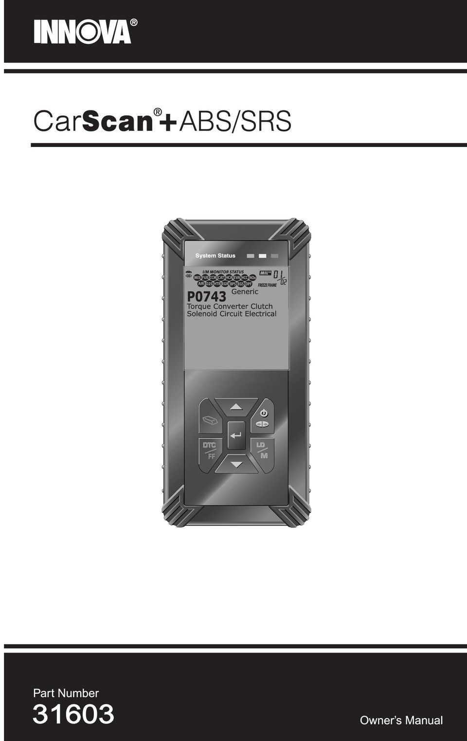
9 Scan Tool Controls CONTROLS AND INDICATORS CONTROLS AND INDICATORS Figure 1. Controls and Indicators See Figure 1 for the locations of items 1 through 12, below. 1. ERASE button - Erases Diagnostic Trouble Codes (DTCs), and Freeze Frame data from your vehicle s computer, and resets Monitor status. 2. ENTER button - When in MENU mode, confirms the selected option or value. 3. button - Displays the DTC View screen and/or scrolls the LCD display to view DTCs and Freeze Frame data. 4. POWER/LINK button - When the Scan Tool IS NOT connected to a vehicle, turns the Scan Tool On and Off. When the Scan Tool is connected to a vehicle, links the Scan Tool to the vehicle s PCM to retrieve diagnostic data from the computer s memory. To turn the Scan Tool "On", you must press and hold the POWER/LINK button for approximately 3 seconds. 5. button When pressed while linked to a vehicle, places the Scan Tool in "Live Data" mode. When pressed and held while linked to a vehicle, displays the Mode Selection Menu. CarScan+ ABS/SRS 7

10 Scan Tool Controls DISPLAY FUNCTIONS 6. DOWN button - When in MENU mode, scrolls DOWN through the menu and submenu selection options. When LINKED to a vehicle, scrolls DOWN through the current display screen to display any additional data. 7. UP button - When in MENU mode, scrolls UP through the menu and submenu selection options. When LINKED to a vehicle, scrolls UP through the current display screen to display any additional data. 8. GREEN LED - Indicates that all engine systems are running normally (all Monitors on the vehicle are active and performing their diagnostic testing, and no DTCs are present). 9. YELLOW LED - Indicates there is a possible problem. A Pending DTC is present and/or some of the vehicle s emission monitors have not run their diagnostic testing. 10. RED LED - Indicates there is a problem in one or more of the vehicle s systems. The red LED is also used to show that DTC(s) are present. DTCs are shown on the Scan Tool s display. In this case, the Malfunction Indicator ( Check Engine ) lamp on the vehicle s instrument panel will light steady on. 11. Display - Displays settings Menu and submenus, test results, Scan Tool functions and Monitor status information. See DISPLAY FUNCTIONS, following, for more details. 12. CABLE - Connects the Scan Tool to the vehicle s Data Link Connector (DLC). DISPLAY FUNCTIONS Figure 2. Display Functions See Figure 2 for the locations of items 1 through 14, following. 1. I/M MONITOR STATUS field - Identifies the I/M Monitor status area. 8 CarScan+ ABS/SRS
. 9.")
11 Scan Tool Controls DISPLAY FUNCTIONS 2. Monitor icons - Indicate which Monitors are supported by the vehicle under test, and whether or not the associated Monitor has run its diagnostic testing (Monitor status). When a Monitor icon is solid, it indicates that the associated Monitor has completed its diagnostic testing. When a Monitor icon is flashing, it indicates that the vehicle supports the associated Monitor, but the Monitor has not yet run its diagnostic testing. 3. Vehicle icon - Indicates whether or not the Scan Tool is being properly powered through the vehicle s Data Link Connector (DLC). A visible icon indicates that the Scan Tool is being powered through the vehicle s DLC connector. 4. Link icon - Indicates whether or not the Scan Tool is communicating (linked) with the vehicle s on-board computer. When visible, the Scan Tool is communicating with the computer. If the Link icon is not visible, the Scan Tool is not communicating with the computer. 5. Computer icon - When this icon is visible it indicates that the Scan Tool is linked to a personal computer. Optional software is available that makes it possible to upload retrieved data to a personal computer. 6. Scan Tool Internal Battery icon - When visible, indicates the Scan Tool batteries are low and should be replaced. If the batteries are not replaced when the battery symbol is "on", all 3 LEDs will light up as a last resort indicator to warn you that the batteries need replacement. No data will be displayed on screen when all 3 LEDs are lit. 7. DTC Display Area - Displays the Diagnostic Trouble Code (DTC) number. Each fault is assigned a code number that is specific to that fault. 8. Test Data Display Area - Displays DTC definitions, Freeze Frame data, Live Data and other pertinent test information messages. 9. FREEZE FRAME icon - Indicates that there is Freeze Frame data from Priority Code (Code #1) stored in the vehicle s computer memory. 10. PERMANENT icon - Indicates the currently displayed DTC is a Permanent code. 11. PENDING icon - Indicates the currently displayed DTC is a Pending code. 12. MIL icon - Indicates the status of the Malfunction Indicator Lamp (MIL). The MIL icon is visible only when a DTC has commanded the MIL on the vehicle s dashboard to light. 13. Code Number Sequence - The Scan Tool assigns a sequence number to each DTC that is present in the computer s memory, starting with 01. This number indicates which code is currently displayed. Code number 01 is always the highest priority code, and the one for which Freeze Frame data has been stored. CarScan+ ABS/SRS 9

12 Scan Tool Controls DISPLAY FUNCTIONS If 01 is a Pending code, there may or may not be Freeze Frame data stored in memory. 14. Code Enumerator - Indicates the total number of codes retrieved from the vehicle s computer. 10 CarScan+ ABS/SRS

13 Onboard Diagnostics COMPUTER ENGINE CONTROLS COMPUTER ENGINE CONTROLS The Introduction of Electronic Engine Controls Electronic Computer Control Systems make it possible for vehicle manufacturers to comply with the tougher emissions and fuel efficiency standards mandated by State and Federal Governments. As a result of increased air pollution (smog) in large cities, such as Los Angeles, the California Air Resources Board (CARB) and the Environmental Protection Agency (EPA) set new regulations and air pollution standards to deal with the problem. To further complicate matters, the energy crisis of the early 1970s caused a sharp increase in fuel prices over a short period. As a result, vehicle manufacturers were not only required to comply with the new emissions standards, they also had to make their vehicles more fuel-efficient. Most vehicles were required to meet a miles-per-gallon (MPG) standard set by the U.S. Federal Government. Precise fuel delivery and spark timing are needed to reduce vehicle emissions. Mechanical engine controls in use at the time (such as ignition points, mechanical spark advance and the carburetor) responded too slowly to driving conditions to properly control fuel delivery and spark timing. This made it difficult for vehicle manufacturers to meet the new standards. A new Engine Control System had to be designed and integrated with the engine controls to meet the stricter standards. The new system had to: Respond instantly to supply the proper mixture of air and fuel for any driving condition (idle, cruising, low-speed driving, high-speed driving, etc.). Calculate instantly the best time to ignite the air/fuel mixture for maximum engine efficiency. Perform both these tasks without affecting vehicle performance or fuel economy. Vehicle Computer Control Systems can perform millions of calculations each second. This makes them an ideal substitute for the slower mechanical engine controls. By switching from mechanical to electronic engine controls, vehicle manufacturers are able to control fuel delivery and spark timing more precisely. Some newer Computer Control Systems also provide control over other vehicle functions, such as transmission, brakes, charging, body, and suspension systems. CarScan+ ABS/SRS 11

14 Onboard Diagnostics COMPUTER ENGINE CONTROLS The Basic Engine Computer Control System The Computer Control System consists of an on-board computer and several related control devices (sensors, switches, and actuators). The on-board computer is the heart of the Computer Control System. The computer contains several programs with preset reference values for air/fuel ratio, spark or ignition timing, injector pulse width, engine speed, etc. Separate values are provided for various driving conditions, such as idle, low speed driving, high-speed driving, low load, or high load. The preset reference values represent the ideal air/fuel mixture, spark timing, transmission gear selection, etc., for any driving condition. These values are programmed by the vehicle manufacturer, and are specific to each vehicle model. Most on-board computers are located inside the vehicle behind the dashboard, under the passenger s or driver s seat, or behind the right kick panel. However, some manufacturers may still position it in the engine compartment. Vehicle sensors, switches, and actuators are located throughout the engine, and are connected by electrical wiring to the on-board computer. These devices include oxygen sensors, coolant temperature sensors, throttle position sensors, fuel injectors, etc. Sensors and switches are input devices. They provide signals representing current engine operating conditions to the computer. Actuators are output devices. They perform actions in response to commands received from the computer. The on-board computer receives information inputs from sensors and switches located throughout the engine. These devices monitor critical engine conditions such as coolant temperature, engine speed, engine load, throttle position, air/fuel ratio etc. The computer compares the values received from these sensors with its preset reference values, and makes corrective actions as needed so that the sensor values always match the preset reference values for the current driving condition. The computer makes adjustments by commanding other devices such as the fuel injectors, idle air control, EGR valve or Ignition Module to perform these actions. OUTPUT DEVICES Fuel Injectors Idle Air Control EGR Valve Ignition Module TYPICAL COMPUTER CONTROL SYSTEM On-Board Computer INPUT DEVICES Coolant Temperature Sensor Throttle Position Sensor Fuel Injectors INPUT DEVICES Oxygen Sensors 12 CarScan+ ABS/SRS

15 Onboard Diagnostics COMPUTER ENGINE CONTROLS Vehicle operating conditions are constantly changing. The computer continuously makes adjustments or corrections (especially to the air/fuel mixture and spark timing) to keep all the engine systems operating within the preset reference values. On-Board Diagnostics - First Generation (OBD1) With the exception of some 1994 and 1995 vehicles, most vehicles from 1982 to 1995 are equipped with some type of first generation On-Board Diagnostics. Beginning in 1988, California s Air Resources Board (CARB), and later the Environmental Protection Agency (EPA) required vehicle manufacturers to include a self-diagnostic program in their on-board computers. The program would be capable of identifying emissions-related faults in a system. The first generation of Onboard Diagnostics came to be known as OBD1. OBD1 is a set of self-testing and diagnostic instructions programmed into the vehicle s on-board computer. The programs are specifically designed to detect failures in the sensors, actuators, switches and wiring of the various vehicle emissions-related systems. If the computer detects a failure in any of these components or systems, it lights an indicator on the dashboard to alert the driver. The indicator lights only when an emissions-related problem is detected. The computer also assigns a numeric code for each specific problem that it detects, and stores these codes in its memory for later retrieval. These codes can be retrieved from the computer s memory with the use of a Code Reader or a Scan Tool. On-Board Diagnostics - Second Generation (OBD2) In addition to performing all the functions of the OBD1 System, the The OBD2 System is OBD2 System has been enhanced with an enhancement of the new Diagnostic Programs. These programs closely monitor the functions OBD1 System. of various emissions-related components and systems (as well as other systems) and make this information readily available (with the proper equipment) to the technician for evaluation. The California Air Resources Board (CARB) conducted studies on OBD1 equipped vehicles. The information that was gathered from these studies showed the following: A large number of vehicles had deteriorating or degraded emissions-related components. These components were causing an increase in emissions. CarScan+ ABS/SRS 13
, and later the Environmental Protection Agency (EPA) required vehicle manufacturers to include a self-diagnostic program in their on-board")
16 Onboard Diagnostics COMPUTER ENGINE CONTROLS Because OBD1 systems only detect failed components, the degraded components were not setting codes. Some emissions problems related to degraded components only occur when the vehicle is being driven under a load. The emission checks being conducted at the time were not performed under simulated driving conditions. As a result, a significant number of vehicles with degraded components were passing Emissions Tests. Codes, code definitions, diagnostic connectors, communication protocols and emissions terminology were different for each manufacturer. This caused confusion for the technicians working on different make and model vehicles. To address the problems made evident by this study, CARB and the EPA passed new laws and standardization requirements. These laws required that vehicle manufacturers to equip their new vehicles with devices capable of meeting all of the new emissions standards and regulations. It was also decided that an enhanced on-board diagnostic system, capable of addressing all of these problems, was needed. This new system is known as On-Board Diagnostics Generation Two (OBD2). The primary objective of the OBD2 system is to comply with the latest regulations and emissions standards established by CARB and the EPA. The Main Objectives of the OBD2 System are: To detect degraded and/or failed emissions-related components or systems that could cause tailpipe emissions to exceed by 1.5 times the Federal Test Procedure (FTP) standard. To expand emissions-related system monitoring. This includes a set of computer run diagnostics called Monitors. Monitors perform diagnostics and testing to verify that all emissions-related components and/or systems are operating correctly and within the manufacturer s specifications. To use a standardized Diagnostic Link Connector (DLC) in all vehicles. (Before OBD2, DLCs were of different shapes and sizes.) To standardize the code numbers, code definitions and language used to describe faults. (Before OBD2, each vehicle manufacturer used their own code numbers, code definitions and language to describe the same faults.) To expand the operation of the Malfunction Indicator Lamp (MIL). To standardize communication procedures and protocols between the diagnostic equipment (Scan Tools, Code Readers, etc.) and the vehicle s on-board computer. OBD2 Terminology The following terms and their definitions are related to OBD2 systems. Read and reference this list as needed to aid in the understanding of OBD2 systems. 14 CarScan+ ABS/SRS

17 Onboard Diagnostics COMPUTER ENGINE CONTROLS Powertrain Control Module (PCM) - The PCM is the OBD2 accepted term for the vehicle s on-board computer. In addition to controlling the engine management and emissions systems, the PCM also participates in controlling the powertrain (transmission) operation. Most PCMs also have the ability to communicate with other computers on the vehicle (ABS, ride control, body, etc.). Monitor - Monitors are diagnostic routines programmed into the PCM. The PCM utilizes these programs to run diagnostic tests, and to monitor operation of the vehicle s emissions-related components or systems to ensure they are operating correctly and within the vehicle s manufacturer specifications. Currently, up to fifteen Monitors are used in OBD2 systems. Additional Monitors will be added as the OBD2 system is further developed. Not all vehicles support all fifteen Monitors. Enabling Criteria - Each Monitor is designed to test and monitor the operation of a specific part of the vehicle s emissions system (EGR system, oxygen sensor, catalytic converter, etc.). A specific set of conditions or driving procedures must be met before the computer can command a Monitor to run tests on its related system. These conditions are known as Enabling Criteria. The requirements and procedures vary for each Monitor. Some Monitors only require the ignition key to be turned On for them to run and complete their diagnostic testing. Others may require a set of complex procedures, such as, starting the vehicle when cold, bringing it to operating temperature, and driving the vehicle under specific conditions before the Monitor can run and complete its diagnostic testing. Monitor Has/Has Not Run - The terms Monitor has run or Monitor has not run are used throughout this manual. Monitor has run, means the PCM has commanded a particular Monitor to perform the required diagnostic testing on a system to ensure the system is operating correctly (within factory specifications). The term Monitor has not run means the PCM has not yet commanded a particular Monitor to perform diagnostic testing on its associated part of the emissions system. Trip - A Trip for a particular Monitor requires that the vehicle is being driven in such a way that all the required Enabling Criteria for the Monitor to run and complete its diagnostic testing are met. The Trip Drive Cycle for a particular Monitor begins when the ignition key is turned On. It is successfully completed when all the Enabling Criteria for the Monitor to run and complete its diagnostic testing are met by the time the ignition key is turned Off. Since each of the fifteen monitors is designed to run diagnostics and testing on a different part of the engine or emissions system, the Trip Drive Cycle needed for each individual Monitor to run and complete varies. CarScan+ ABS/SRS 15

18 Onboard Diagnostics DIAGNOSTIC TROUBLE CODES (DTCs) OBD2 Drive Cycle - An OBD2 Drive Cycle is an extended set of driving procedures that takes into consideration the various types of driving conditions encountered in real life. These conditions may include starting the vehicle when it is cold, driving the vehicle at a steady speed (cruising), accelerating, etc. An OBD2 Drive Cycle begins when the ignition key is turned On (when cold) and ends when the vehicle has been driven in such a way as to have all the Enabling Criteria met for all its applicable Monitors. Only those trips that provide the Enabling Criteria for all Monitors applicable to the vehicle to run and complete their individual diagnostic tests qualify as an OBD2 Drive Cycle. OBD2 Drive Cycle requirements vary from one model of vehicle to another. Vehicle manufacturers set these procedures. Consult your vehicle s service manual for OBD2 Drive Cycle procedures. Do not confuse a Trip Drive Cycle with an OBD2 Drive Cycle. A Trip Drive Cycle provides the Enabling Criteria for one specific Monitor to run and complete its diagnostic testing. An OBD2 Drive Cycle must meet the Enabling Criteria for all Monitors on a particular vehicle to run and complete their diagnostic testing. Warm-up Cycle - Vehicle operation after an engine off period where engine temperature rises at least 40 F (22 C) from its temperature before starting, and reaches at least 160 F (70 C). The PCM uses warm-up cycles as a counter to automatically erase a specific code and related data from its memory. When no faults related to the original problem are detected within a specified number of warm-up cycles, the code is erased automatically. DIAGNOSTIC TROUBLE CODES (DTCs) Diagnostic Trouble Codes (DTCs) are meant to guide you to the proper service procedure in the vehicle s service manual. DO NOT replace parts based only on DTCs without first consulting the vehicle s service manual for proper testing procedures for that particular system, circuit or component. Diagnostic Trouble Codes (DTCs) are codes that identify a specific problem area. DTCs are alphanumeric codes that are used to identify a problem that is present in any of the systems that are monitored by the on-board computer (PCM). Each trouble code has an assigned message that identifies the circuit, component or system area where the problem was found. OBD2 diagnostic trouble codes are made up of five characters: The 1st character is a letter (B, C, P or U). It identifies the main system where the fault occurred (Body, Chassis, Powertrain, or Network). The 2nd character is a numeric digit (0 thru 3). It identifies the type of code (Generic or Manufacturer-Specific). Generic DTCs are codes that are used by all vehicle manufacturers. The standards for generic DTCs, as well as their definitions, are set by the Society of Automotive Engineers (SAE). 16 CarScan+ ABS/SRS

19 Onboard Diagnostics DIAGNOSTIC TROUBLE CODES (DTCs) Manufacturer-Specific DTCs are codes that are controlled by the vehicle manufacturers. The Federal Government does not require vehicle manufacturers to go beyond the standardized generic DTCs in order to comply with the new OBD2 emissions standards. However, manufacturers are free to expand beyond the standardized codes to make their systems easier to diagnose. The 3rd character is a letter or a numeric digit (0 thru 9, A thru F). It identifies the specific system or sub-system where the problem is located. The 4th and 5th characters are letters or numeric digits (0 thru 9, A thru F). They identify the section of the system that is malfunctioning. OBD2 DTC EXAMPLE P Injector Circuit Malfunction, Cylinder 1 B C P U - Body Chassis Powertrain Network P Generic Manufacturer Specific Generic ("P" Codes) and Manufacturer Specific ("B", "C" and "U" Codes) Includes both Generic and Manufacturer Specific Codes Identifies the system where the problem is located. "P" Code systems are listed below. "B", "C" and "U" Code systems will vary. 0 - Fuel and Air Metering; Auxiliary Emission Controls 1 - Fuel and Air Metering Fuel and Air Metering (injector circuit malfunction only) Ignition System or Misfire Auxiliary Emission Control System Vehicle Speed Control and Idle Control System Computer Output Circuits Transmission Transmission 9 - Transmission A - Hybrid Propulsion B - Hybrid Propulsion C - Hybrid Propulsion Identifies what section of the system is malfunctioning CarScan+ ABS/SRS 17
.")
20 Onboard Diagnostics DIAGNOSTIC TROUBLE CODES (DTCs) DTCs and MIL Status When the vehicle s on-board computer detects a failure in an emissions-related component or system, the computer s internal diagnostic program assigns a diagnostic trouble code (DTC) that points to the system (and subsystem) where the fault was found. The diagnostic program saves the code in the computer s memory. It records a Freeze Frame of conditions present when the fault was found, and lights the Malfunction Indicator Lamp (MIL). Some faults require detection for two trips in a row before the MIL is turned on. The Malfunction Indicator Lamp (MIL) is the accepted term used to describe the lamp on the dashboard that lights to warn the driver that an emissions-related fault has been found. Some manufacturers may still call this lamp a Check Engine or Service Engine Soon light. There are two types of DTCs used for emissions-related faults: Type A and Type B. Type A codes are One-Trip codes; Type B DTCs are usually Two-Trip DTCs. When a Type A DTC is found on the First Trip, the following events take place: The computer commands the MIL On when the failure is first found. If the failure causes a severe misfire that may cause damage to the catalytic converter, the MIL flashes once per second. The MIL continues to flash as long as the condition exists. If the condition that caused the MIL to flash is no longer present, the MIL will light steady On. A DTC is saved in the computer s memory for later retrieval. A Freeze Frame of the conditions present in the engine or emissions system when the MIL was ordered On is saved in the computer s memory for later retrieval. This information shows fuel system status (closed loop or open loop), engine load, coolant temperature, fuel trim value, MAP vacuum, engine RPM and DTC priority. When a Type B DTC is found on the First Trip, the following events take place: The computer sets a Pending DTC, but the MIL is not ordered On. Freeze Frame data may or may not be saved at this time depending on manufacturer. The Pending DTC is saved in the computer s memory for later retrieval. If the failure is found on the second consecutive trip, the MIL is ordered On. Freeze Frame data is saved in the computer s memory. If the failure is not found on the second Trip, the Pending DTC is erased from the computer s memory. The MIL will stay lit for both Type A and Type B codes until one of the following conditions occurs: 18 CarScan+ ABS/SRS

21 Onboard Diagnostics OBD2 MONITORS If the conditions that caused the MIL to light are no longer present for the next three trips in a row, the computer automatically turns the MIL Off if no other emissions-related faults are present. However, the DTCs remain in the computer s memory as a history code for 40 warm-up cycles (80 warm-up cycles for fuel and misfire faults). The DTCs are automatically erased if the fault that caused them to be set is not detected again during that period. Misfire and fuel system faults require three trips with similar conditions before the MIL is turned Off. These are trips where the engine load, RPM and temperature are similar to the conditions present when the fault was first found. After the MIL has been turned off, DTCs and Freeze Frame data stay in the computer s memory. Erasing the DTCs from the computer s memory can also turn off the MIL. See ERASING DIAGNOSTIC TROUBLE CODES (DTCs) on page 53, before erasing codes from the computer s memory. If a Diagnostic Tool or Scan Tool is used to erase the codes, Freeze Frame data will also be erased. OBD2 MONITORS To ensure the correct operation of the various emissions-related components and systems, a diagnostic program was developed and installed in the vehicle s on-board computer. The program has several procedures and diagnostic strategies. Each procedure or diagnostic strategy is made to monitor the operation of, and run diagnostic tests on, a specific emissions-related component or system. These tests ensure the system is running correctly and is within the manufacturer s specifications. On OBD2 systems, these procedures and diagnostic strategies are called Monitors. Currently, fifteen Monitors are supported by OBD2 systems. Additional monitors may be added as a result of Government regulations as the OBD2 system grows and matures. Not all vehicles support all fifteen Monitors. Additionally, some Monitors are supported by spark ignition vehicles only, while others are supported by compression ignition vehicles only. Monitor operation is either Continuous or Non-Continuous, depending on the specific monitor. Continuous Monitors Three of these Monitors are designed to constantly monitor their associated components and/or systems for proper operation. Continuous Monitors run constantly when the engine is running. The Continuous Monitors are: Comprehensive Component Monitor (CCM) Misfire Monitor Fuel System Monitor CarScan+ ABS/SRS 19
22 Onboard Diagnostics OBD2 MONITORS Non-Continuous Monitors The other twelve Monitors are non-continuous Monitors. Noncontinuous Monitors perform and complete their testing once per trip. The non-continuous Monitors are: Oxygen Sensor Monitor Oxygen Sensor Heater Monitor Catalyst Monitor Heated Catalyst Monitor EGR System Monitor EVAP System Monitor Secondary Air System Monitor The following Monitors became standard beginning in The majority of vehicles produced before this time will not support these Monitors NMHC Monitor NOx Adsorber Monitor Boost Pressure System Monitor Exhaust Gas Sensor Monitor PM Filter Monitor The following provides a brief explanation of the function of each Monitor: Comprehensive Component Monitor (CCM) - This Monitor continuously checks all inputs and outputs from sensors, actuators, switches and other devices that provide a signal to the computer. The Monitor checks for shorts, opens, out of range value, functionality and rationality. Rationality: Each input signal is compared against all other inputs and against information in the computer s memory to see if it makes sense under the current operating conditions. Example: The signal from the throttle position sensor indicates the vehicle is in a wide-open throttle condition, but the vehicle is really at idle, and the idle condition is confirmed by the signals from all other sensors. Based on the input data, the computer determines that the signal from the throttle position sensor is not rational (does not make sense when compared to the other inputs). In this case, the signal would fail the rationality test. The CCM is supported by both spark ignition vehicles and compression ignition vehicles. The CCM may be either a One-Trip or a Two-Trip Monitor, depending on the component. 20 CarScan+ ABS/SRS
23 Onboard Diagnostics OBD2 MONITORS Fuel System Monitor - This Monitor uses a Fuel System Correction program, called Fuel Trim, inside the on-board computer. Fuel Trim is a set of positive and negative values that represent adding or subtracting fuel from the engine. This program is used to correct for a lean (too much air/not enough fuel) or rich (too much fuel/not enough air) air-fuel mixture. The program is designed to add or subtract fuel, as needed, up to a certain percent. If the correction needed is too large and exceeds the time and percent allowed by the program, a fault is indicated by the computer. The Fuel System Monitor is supported by both spark ignition vehicles and compression ignition vehicles. The Fuel System Monitor may be a One-Trip or Two-Trip Monitor, depending on the severity of the problem. Misfire Monitor - This Monitor continuously checks for engine misfires. A misfire occurs when the air-fuel mixture in the cylinder does not ignite. The misfire Monitor uses changes in crankshaft speed to sense an engine misfire. When a cylinder misfires, it no longer contributes to the speed of the engine, and engine speed decreases each time the affected cylinder(s) misfire. The misfire Monitor is designed to sense engine speed fluctuations and determine from which cylinder(s) the misfire is coming, as well as how bad the misfire is. There are three types of engine misfires, Types 1, 2, and 3. - Type 1 and Type 3 misfires are two-trip monitor faults. If a fault is sensed on the first trip, the computer temporarily saves the fault in its memory as a Pending Code. The MIL is not commanded on at this time. If the fault is found again on the second trip, under similar conditions of engine speed, load and temperature, the computer commands the MIL On, and the code is saved in its long term memory. - Type 2 misfires are the most severe type of misfire. When a Type 2 misfire is sensed on the first trip, the computer commands the MIL to light when the misfire is sensed. If the computer determines that a Type 2 misfire is severe, and may cause catalytic converter damage, it commands the MIL to flash once per second as soon as the misfire is sensed. When the misfire is no longer present, the MIL reverts to steady On condition. The Misfire Monitor is supported by both spark ignition vehicles and compression ignition vehicles. Catalyst Monitor - The catalytic converter is a device that is installed downstream of the exhaust manifold. It helps to oxidize (burn) the unburned fuel (hydrocarbons) and partially burned fuel (carbon monoxide) left over from the combustion process. To accomplish this, heat and catalyst materials inside the converter react with the exhaust gases to burn the remaining fuel. Some materials inside the catalytic converter also have the ability to store oxygen, and release it as needed to oxidize hydrocarbons and carbon monoxide. In the process, it reduces vehicle emissions by converting the polluting gases into carbon dioxide and water. The computer checks the efficiency of the catalytic converter by monitoring the oxygen sensors used by the system. One sensor is located before (upstream of) the converter; the other is located after (downstream of) the converter. If the catalytic converter loses its ability to store oxygen, CarScan+ ABS/SRS 21
24 Onboard Diagnostics OBD2 MONITORS the downstream sensor signal voltage becomes almost the same as the upstream sensor signal. In this case, the monitor fails the test. The Catalyst Monitor is supported by spark ignition vehicles only. The Catalyst Monitor is a Two-Trip Monitor. If a fault is found on the first trip, the computer temporarily saves the fault in its memory as a Pending Code. The computer does not command the MIL on at this time. If the fault is sensed again on the second trip, the computer commands the MIL On and saves the code in its long-term memory. Heated Catalyst Monitor - Operation of the heated catalytic converter is similar to the catalytic converter. The main difference is that a heater is added to bring the catalytic converter to its operating temperature more quickly. This helps reduce emissions by reducing the converter s down time when the engine is cold. The Heated Catalyst Monitor performs the same diagnostic tests as the catalyst Monitor, and also tests the catalytic converter s heater for proper operation. The Heated Catalyst Monitor is supported by spark ignition vehicles only. This Monitor is also a Two-Trip Monitor. Exhaust Gas Recirculation (EGR) Monitor - The Exhaust Gas Recirculation (EGR) system helps reduce the formation of Oxides of Nitrogen during combustion. Temperatures above 2500 F cause nitrogen and oxygen to combine and form Oxides of Nitrogen in the combustion chamber. To reduce the formation of Oxides of Nitrogen, combustion temperatures must be kept below 2500 F. The EGR system recirculates small amounts of exhaust gas back into the intake manifold, where it is mixed with the incoming air/fuel mixture. This reduces combustion temperatures by up to 500 F. The computer determines when, for how long, and how much exhaust gas is recirculated back to the intake manifold. The EGR Monitor performs EGR system function tests at preset times during vehicle operation. The EGR Monitor is supported by both spark ignition vehicles and compression ignition vehicles. The EGR Monitor is a Two-Trip Monitor. If a fault is found on the first trip, the computer temporarily saves the fault in its memory as a Pending Code. The computer does not command the MIL on at this time. If the fault is sensed again on the second trip, the computer commands the MIL On, and saves the code in its long-term memory. Evaporative System (EVAP) Monitor - OBD2 vehicles are equipped with a fuel Evaporative system (EVAP) that helps prevent fuel vapors from evaporating into the air. The EVAP system carries fumes from the fuel tank to the engine where they are burned during combustion. The EVAP system may consist of a charcoal canister, fuel tank cap, purge solenoid, vent solenoid, flow monitor, leak detector and connecting tubes, lines and hoses. Fumes are carried from the fuel tank to the charcoal canister by hoses or tubes. The fumes are stored in the charcoal canister. The computer controls the flow of fuel vapors from the charcoal canister to the engine via a purge solenoid. The computer energizes or de-energizes the purge solenoid (depending on solenoid design). The purge solenoid opens a valve to allow engine vacuum to draw the fuel vapors from the canister 22 CarScan+ ABS/SRS
25 Onboard Diagnostics OBD2 MONITORS into the engine where the vapors are burned. The EVAP Monitor checks for proper fuel vapor flow to the engine, and pressurizes the system to test for leaks. The computer runs this Monitor once per trip. The EVAP Monitor is supported by spark ignition vehicles only. The EVAP Monitor is a Two-Trip Monitor. If a fault is found on the first trip, the computer temporarily saves the fault in its memory as a Pending Code. The computer does not command the MIL on at this time. If the fault is sensed again on the second trip, the PCM commands the MIL On, and saves the code in its long-term memory. Oxygen Sensor Heater Monitor - The Oxygen Sensor Heater Monitor tests the operation of the oxygen sensor s heater. There are two modes of operation on a computer-controlled vehicle: openloop and closed-loop. The vehicle operates in open-loop when the engine is cold, before it reaches normal operating temperature. The vehicle also goes to open-loop mode at other times, such as heavy load and full throttle conditions. When the vehicle is running in open-loop, the oxygen sensor signal is ignored by the computer for air/fuel mixture corrections. Engine efficiency during open-loop operation is very low, and results in the production of more vehicle emissions. Closed-loop operation is the best condition for both vehicle emissions and vehicle operation. When the vehicle is operating in closed-loop, the computer uses the oxygen sensor signal for air/fuel mixture corrections. In order for the computer to enter closed-loop operation, the oxygen sensor must reach a temperature of at least 600 F. The oxygen sensor heater helps the oxygen sensor reach and maintain its minimum operating temperature (600 F) more quickly, to bring the vehicle into closed-loop operation as soon as possible. The Oxygen Sensor Heater Monitor is supported by spark ignition vehicles only. The Oxygen Sensor Heater Monitor is a Two-Trip Monitor. If a fault is found on the first trip, the computer temporarily saves the fault in its memory as a Pending Code. The computer does not command the MIL on at this time. If the fault is sensed again on the second trip, the computer commands the MIL On, and saves the code in its long-term memory. Oxygen Sensor Monitor - The Oxygen Sensor monitors how much oxygen is in the vehicle s exhaust. It generates a varying voltage of up to one volt, based on how much oxygen is in the exhaust gas, and sends the signal to the computer. The computer uses this signal to make corrections to the air/fuel mixture. If the exhaust gas has a large amount of oxygen (a lean air/fuel mixture), the oxygen sensor generates a low voltage signal. If the exhaust gas has very little oxygen (a rich mixture condition), the oxygen sensor generates a high voltage signal. A 450mV signal indicates the most efficient, and least polluting, air/fuel ratio of 14.7 parts of air to one part of fuel. The oxygen sensor must reach a temperature of at least F, and the engine must reach normal operating temperature, for the computer to enter into closed-loop operation. The oxygen sensor only functions when the computer is in closed-loop. A properly operating oxygen sensor reacts quickly to any change in oxygen content in the CarScan+ ABS/SRS 23
26 Onboard Diagnostics OBD2 MONITORS exhaust stream. A faulty oxygen sensor reacts slowly, or its voltage signal is weak or missing. The Oxygen Sensor Monitor is supported by spark ignition vehicles only. The Oxygen Sensor Monitor is a Two-Trip monitor. If a fault is found on the first trip, the computer temporarily saves the fault in its memory as a Pending Code. The computer does not command the MIL on at this time. If the fault is sensed again on the second trip, the computer commands the MIL On, and saves the code in its long-term memory. Secondary Air System Monitor - When a cold engine is first started, it runs in open-loop mode. During open-loop operation, the engine usually runs rich. A vehicle running rich wastes fuel and creates increased emissions, such as carbon monoxide and some hydrocarbons. A Secondary Air System injects air into the exhaust stream to aid catalytic converter operation: 1. It supplies the catalytic converter with the oxygen it needs to oxidize the carbon monoxide and hydrocarbons left over from the combustion process during engine warm-up. 2. The extra oxygen injected into the exhaust stream also helps the catalytic converter reach operating temperature more quickly during warm-up periods. The catalytic converter must heat to operating temperature to work properly. The Secondary Air System Monitor checks for component integrity and system operation, and tests for faults in the system. The computer runs this Monitor once per trip. The Secondary Air System Monitor is a Two-Trip monitor. If a fault is found on the first trip, the computer temporarily saves this fault in its memory as a Pending Code. The computer does not command the MIL on at this time. If the fault is sensed again on the second trip, the computer commands the MIL On, and saves the code in its long-term memory. Non-Methane Hydrocarbon Catalyst (NMHC) Monitor - The non-methane hydrocarbon catalyst is a type of catalytic converter. It helps to remove non-methane hydrocarbons (NMH) left over from the combustion process from the exhaust stream. To accomplish this, heat and catalyst materials react with the exhaust gases to convert NMH to less harmful compounds. The computer checks the efficiency of the catalyst by monitoring the quantity of NMH in the exhaust stream. The monitor also verifies that sufficient temperature is present to aid in particulate matter (PM) filter regeneration. The NMHC Monitor is supported by compression ignition vehicles only. The NMHC Monitor is a Two-Trip Monitor. If a fault is found on the first trip, the computer temporarily saves the fault in its memory as a Pending Code. The computer does not command the MIL on at this time. If the fault is sensed again on the second trip, the computer commands the MIL On, and saves the code in its long-term memory. 24 CarScan+ ABS/SRS
27 Onboard Diagnostics OBD2 MONITORS NOx Aftertreatment Monitor - NOx aftertreatment is based on a catalytic converter support that has been coated with a special washcoat containing zeolites. NOx Aftertreatment is designed to reduce oxides of nitrogen emitted in the exhaust stream. The zeolite acts as a molecular "sponge" to trap the NO and NO2 molecules in the exhaust stream. In some implementations, injection of a reactant before the aftertreatment purges it. NO2 in particular is unstable, and will join with hydrocarbons to produce H2O and N2. The NOx Aftertreatment Monitor monitors the function of the NOx aftertreatment to ensure that tailpipe emissions remain within acceptable limits. The NOx Aftertreatment Monitor is supported by compression ignition vehicles only. The NOx Aftertreatment Monitor is a Two-Trip Monitor. If a fault is found on the first trip, the computer temporarily saves the fault in its memory as a Pending Code. The computer does not command the MIL on at this time. If the fault is sensed again on the second trip, the computer commands the MIL On, and saves the code in its long-term memory. Boost Pressure System Monitor - The boost pressure system serves to increase the pressure produced inside the intake manifold to a level greater than atmospheric pressure. This increase in pressure helps to ensure compete combustion of the air-fuel mixture. The Boost Pressure System Monitor checks for component integrity and system operation, and tests for faults in the system. The computer runs this Monitor once per trip. The Boost Pressure System Monitor is supported by compression ignition vehicles only. The Boost Pressure System Monitor is a Two- Trip Monitor. If a fault is found on the first trip, the computer temporarily saves the fault in its memory as a Pending Code. The computer does not command the MIL on at this time. If the fault is sensed again on the second trip, the computer commands the MIL On, and saves the code in its long-term memory. Exhaust Gas Sensor Monitor - The exhaust gas sensor is used by a number of systems/monitors to determine the content of the exhaust stream. The computer checks for component integrity, system operation, and tests for faults in the system, as well as feedback faults that may affect other emission control systems. The Exhaust Gas Sensor Monitor is supported by compression ignition vehicles only. The Exhaust Gas Sensor Monitor is a Two-Trip Monitor. If a fault is found on the first trip, the computer temporarily saves the fault in its memory as a Pending Code. The computer does not command the MIL on at this time. If the fault is sensed again on the second trip, the computer commands the MIL On, and saves the code in its long-term memory. CarScan+ ABS/SRS 25
28 Onboard Diagnostics OBD2 MONITORS PM Filter Monitor - The particulate matter (PM) filter removes particulate matter from the exhaust stream by filtration. The filter has a honeycomb structure similar to a catalyst substrate, but with the channels blocked at alternate ends. This forces the exhaust gas to flow through the walls between the channels, filtering the particulate matter out. The filters are self-cleaning by periodic modification of the exhaust gas concentration in order to burn off the trapped particles (oxidizing the particles to form CO2 and water). The computer monitors the efficiency of the filter in trapping particulate matter, as well as the ability of the filter to regenerate (self-clean). The PM Filter Monitor is supported by compression ignition vehicles only. The PM Filter Monitor is a Two-Trip Monitor. If a fault is found on the first trip, the computer temporarily saves the fault in its memory as a Pending Code. The computer does not command the MIL on at this time. If the fault is sensed again on the second trip, the computer commands the MIL On, and saves the code in its long-term memory. OBD2 Reference Table The table below lists current OBD2 Monitors, and indicates the following for each Monitor: A. Monitor Type (how often does the Monitor run; Continuous or Once per trip) B. Number of trips needed, with a fault present, to set a pending DTC C. Number of consecutive trips needed, with a fault present, to command the MIL On and store a DTC D. Number of trips needed, with no faults present, to erase a Pending DTC E. Number and type of trips or drive cycles needed, with no faults present, to turn off the MIL F. Number of warm-up periods needed to erase the DTC from the computer s memory after the MIL is turned off 26 CarScan+ ABS/SRS
29 Onboard Diagnostics OBD2 MONITORS Name of Monitor A B C D E F Comprehensive Component Monitor Continuous Misfire Monitor (Type 1 and 3) Misfire Monitor (Type 2) Fuel System Monitor Catalytic Converter Monitor Oxygen Sensor Monitor Oxygen Sensor Heater Monitor Exhaust Gas Recirculation (EGR) Monitor Evaporative Emissions Controls Monitor Secondary Air System (AIR) Monitor NMHC Monitor NOx Adsorber Monitor Boost Pressure System Monitor Exhaust Gas Sensor Monitor PM Filter Monitor Continuous Continuous 1 Continuous 1 1 or 2 1 Once per trip Once per trip Once per trip Once per trip Once per trip Once per trip Once per trip Once per trip Once per trip Once per trip Once per trip 3 - similar conditions 3 - similar conditions 3 - similar conditions trips trips trips trips trips trips trips trips trips trips trips 40 CarScan+ ABS/SRS 27
30 Preparation for Testing PRELIMINARY VEHICLE DIAGNOSTIC WORKSHEET PRELIMINARY VEHICLE DIAGNOSTIC WORKSHEET The purpose of this form is to help you gather preliminary information on your vehicle before you retrieve codes. By having a complete account of your vehicle's current problem(s), you will be able to systematically pinpoint the problem(s) by comparing your answers to the fault codes you retrieve. You can also provide this information to your mechanic to assist in diagnosis and help avoid costly and unnecessary repairs. It is important for you to complete this form to help you and/or your mechanic have a clear understanding of your vehicle's problems. NAME: DATE: VIN*: YEAR: MAKE: MODEL: ENGINE SIZE: VEHICLE MILEAGE: *VIN: Vehicle Identification Number, found at the base of the windshield on a metallic plate, or at the driver door latch area (consult your vehicle owner's manual for location). TRANSMISSION: Automatic Manual Please check all applicable items in each category. DESCRIBE THE PROBLEM: 28 CarScan+ ABS/SRS
31 Preparation for Testing PRELIMINARY VEHICLE DIAGNOSTIC WORKSHEET WHEN DID YOU FIRST NOTICE THE PROBLEM: Just Started Started Last Week Started Last Month Other: LIST ANY REPAIRS DONE IN THE PAST SIX MONTHS: m PROBLEMS STARTING No symptoms Will not crank ENGINE QUITS OR STALLS No symptoms Right after starting When shifting into gear During steady-speed driving IDLING CONDITIONS No symptoms Is too slow at all times Is too fast RUNNING CONDITIONS No symptoms Runs rough Lacks power Bucks and jerks Poor fuel economy Hesitates or stumbles on accelerations Cranks, but will not start Starts, but takes a long time Right after vehicle comes to a stop While idling During acceleration When parking Is sometimes too fast or too slow Is rough or uneven Fluctuates up and down Backfires Misfires or cuts out Engine knocks, pings or rattles Surges Dieseling or run-on CarScan+ ABS/SRS 29
32 Preparation for Testing PRELIMINARY VEHICLE DIAGNOSTIC WORKSHEET AUTOMATIC TRANSMISSION PROBLEMS (if applicable) No symptoms Vehicle does not move Shifts too early or too late when in gear Changes gear incorrectly Jerks or bucks PROBLEM OCCURS Morning Afternoon Anytime ENGINE TEMPERATURE WHEN PROBLEM OCCURS Cold Warm Hot DRIVING CONDITIONS WHEN PROBLEM OCCURS Short - less than 2 miles With headlights on 2-10 miles During acceleration Long - more than 10 miles Mostly driving downhill Stop and go Mostly driving uphill While turning Mostly driving level While braking Mostly driving curvy At gear engagement roads With A/C operating Mostly driving rough roads DRIVING HABITS Mostly city driving Drive less than 10 miles per day Highway Drive 10 to 50 miles per day Park vehicle inside Drive more than 50 miles per Park vehicle outside day GASOLINE USED 87 Octane 89 Octane 91 Octane More than 91 Octane WEATHER CONDITIONS WHEN PROBLEM OCCURS F (0-13 C) Above 55 F (13 C) Below freezing (32 F / 0 C) CHECK ENGINE LIGHT / DASH WARNING LIGHT Sometimes ON Always ON Never ON PECULIAR SMELLS "Hot" Sulfur ("rotten egg") Burning rubber STRANGE NOISES Rattle Knock Gasoline Burning oil Electrical Squeak Other 30 CarScan+ ABS/SRS
33 Preparation for Testing BEFORE YOU BEGIN BEFORE YOU BEGIN The Scan Tool aids in monitoring electronic- and emissionsrelated faults in your vehicle and retrieving fault codes related to malfunctions in these systems. Mechanical problems such as low oil level or damaged hoses, wiring or electrical connectors can cause poor engine performance and may also cause a fault code to set. Fix any known mechanical problems before performing any test. See your vehicle s service manual or a mechanic for more information. Check the following areas before starting any test: Check the engine oil, power steering fluid, transmission fluid (if applicable), engine coolant and other fluids for proper levels. Top off low fluid levels if needed. Make sure the air filter is clean and in good condition. Make sure all air filter ducts are properly connected. Check the air filter ducts for holes, rips or cracks. Make sure all engine belts are in good condition. Check for cracked, torn, brittle, loose or missing belts. Make sure mechanical linkages to engine sensors (throttle, gearshift position, transmission, etc.) are secure and properly connected. See your vehicle s service manual for locations. Check all rubber hoses (radiator) and steel hoses (vacuum/fuel) for leaks, cracks, blockage or other damage. Make sure all hoses are routed and connected properly. Make sure all spark plugs are clean and in good condition. Check for damaged, loose, disconnected or missing spark plug wires. Make sure the battery terminals are clean and tight. Check for corrosion or broken connections. Check for proper battery and charging system voltages. Check all electrical wiring and harnesses for proper connection. Make sure wire insulation is in good condition, and there are no bare wires. Make sure the engine is mechanically sound. If needed, perform a compression check, engine vacuum check, timing check (if applicable), etc. CarScan+ ABS/SRS 31
34 Preparation for Testing VEHICLE SERVICE MANUALS VEHICLE SERVICE MANUALS Always refer to the manufacturer s service manual for your vehicle before performing any test or repair procedures. Contact your local car dealership, auto parts store or bookstore for availability of these manuals. The following companies publish valuable repair manuals: Haynes Publications 861 Lawrence Drive Newbury Park, California Phone: Web: Mitchell Danielson Street Poway, California Phone: Web: Motor Publications 5600 Crooks Road, Suite 200 Troy, Michigan Phone: Web: FACTORY SOURCES Ford, GM, Chrysler, Honda, Isuzu, Hyundai and Subaru Service Manuals Helm Inc Hamilton Avenue Highland Park, Michigan Phone: Web: 32 CarScan+ ABS/SRS
35 Using the Scan Tool CODE RETRIEVAL PROCEDURE CODE RETRIEVAL PROCEDURE Retrieving and using Diagnostic Trouble Codes (DTCs) for troubleshooting vehicle operation is only one part of an overall diagnostic strategy. Never replace a part based only on the DTC definition. Each DTC has a set of testing procedures, instructions and flow charts that must be followed to confirm the location of the problem. This information is found in the vehicle's service manual. Always refer to the vehicle's service manual for detailed testing instructions. Check your vehicle thoroughly before performing any test. See BEFORE YOU BEGIN on page 31 for details. ALWAYS observe safety precautions whenever working on a vehicle. See SAFETY PRECAUTIONS on page 3 for more information. 1. Turn the ignition off. 2. Locate the vehicle's 16-pin Data Link Connector (DLC). See page 5 for connector location. Some DLCs have a plastic cover that must be removed before connecting the Scan Tool cable connector. If the Scan Tool is ON, turn it OFF by pressing the POWER/LINK button BEFORE connecting the Scan Tool to the DLC. 3. Connect the Scan Tool cable connector to the vehicle s DLC. The cable connector is keyed and will only fit one way. If you have problems connecting the cable connector to the DLC, rotate the connector 180 and try again. If you still have problems, check the DLC on the vehicle and on the Scan Tool. Refer to your vehicle s service manual to properly check the vehicle s DLC. 4. Turn the ignition on. DO NOT start the engine. 5. When the Scan Tool s cable connector is properly connected to the vehicle s DLC, the unit automatically turns ON. CarScan+ ABS/SRS 33
36 Using the Scan Tool CODE RETRIEVAL PROCEDURE If the unit does not power on automatically when connected to the vehicle s DLC connector, it usually indicates there is no power present at the vehicle s DLC connector. Check your fuse panel and replace any burned-out fuses. If replacing the fuse(s) does not correct the problem, consult your vehicle s repair manual to identify the proper computer (PCM) fuse/circuit, and perform any necessary repairs before proceeding. 6. The Scan Tool will automatically start a check of the vehicle s computer to determine which type of communication protocol it is using. When the Scan Tool identifies the computer s communication protocol, a communication link is established. The protocol type used by the vehicle s computer is shown on the display. A PROTOCOL is a set of rules and procedures for regulating data transmission between computers, and between testing equipment and computers. As of this writing, five different types of protocols (ISO 9141, Keyword 2000, J1850 PWM, J1850 VPW and CAN) are in use by vehicle manufacturers. The Scan Tool automatically identifies the protocol type and establishes a communication link with the vehicle s computer. 7. After approximately 10~60 seconds, the Scan Tool will retrieve and display any Diagnostic Trouble Codes, Monitor Status and Freeze Frame Data retrieved from the vehicle s computer memory. If the Scan Tool fails to link to the vehicle s computer a Linking Failed message shows on the Scan Tool s display. - Verify the connection at the DLC, and verify the ignition is ON. - Turn the ignition OFF, wait 5 seconds, then turn back ON to reset the computer. - Ensure your vehicle is OBD2 compliant. See VEHICLES COVERED on page 5 for vehicle compliance verification information. 34 CarScan+ ABS/SRS
37 Using the Scan Tool CODE RETRIEVAL PROCEDURE The Scan Tool will display a code only if codes are present in the vehicle s computer memory. If no codes are present, the message No Powertrain DTCs or Freeze Frame Data presently stored in the vehicle s computer. Press the DTC button to view your Enhanced DTC s display. Press the button to enter the enhanced mode (see THE ENHANCED MAIN MENU on page 39). The Scan Tool is capable of retrieving and storing up to 32 codes in memory, for immediate or later viewing. 8. To read the display: Refer to DISPLAY FUNCTIONS on page 8 for a description of display elements. A visible icon indicates that the Scan Tool is being powered through the vehicle s DLC connector. A visible icon indicates that the Scan Tool is linked to (communicating with) the vehicle s computer. The I/M Monitor Status icons indicate the type and number of Monitors the vehicle supports, and provides indications of the current status of the vehicle s Monitors. A solid Monitor icon indicates the associated Monitor has run and completed its testing. A blinking Monitor icon indicates the associated Monitor has not run and completed its testing. The upper right hand corner of the display shows the number of the code currently being displayed, the total number of codes retrieved, and whether or not the displayed code commanded the MIL on. If the code being displayed is a PENDING code, the PENDING icon is shown. If the code being displayed is a PERMANENT code, the PERMA- NENT icon is shown. The Diagnostic Trouble Code (DTC) and related code definition are shown in the lower section of the display. In the case of long code definitions, a small arrow is shown in the upper/lower right-hand corner of the Scan Tool display area to indicate the presence of additional information. Use the and buttons, as necessary, to view the additional information. If a definition for the currently displayed code is not available, an advisory message shows on the Scan Tool s display. 9. Read and interpret Diagnostic Trouble Codes/system condition using the display and the green, yellow and red LEDs. CarScan+ ABS/SRS 35
38 Using the Scan Tool CODE RETRIEVAL PROCEDURE The green, yellow and red LEDs are used (with the display) as visual aids to make it easier to determine engine system conditions. Green LED Indicates that all engine systems are OK and operating normally. All monitors supported by the vehicle have run and performed their diagnostic testing, and no trouble codes are present. All Monitor icons will be solid. Yellow LED Indicates one of the following conditions: A. A PENDING CODE IS PRESENT If the yellow LED is illuminated, it may indicate a Pending code is present. Check the Scan Tool s display for confirmation. A Pending code is confirmed by the presence of a numeric code and the word PENDING on the Scan Tool s display. B. MONITOR NOT RUN STATUS If the Scan Tool s display shows a zero (indicating there are no DTC s present in the vehicle s computer memory), but the yellow LED is illuminated, it may be an indication that some of the Monitors supported by the vehicle have not yet run and completed their diagnostic testing. Check the Scan Tool s display for confirmation. All Monitor icons that are blinking have not yet run and completed their diagnostic testing; all Monitor icons that are solid have run and completed their diagnostic testing. Red LED Indicates there is a problem with one or more of the vehicle s systems. The red LED is also used to indicate that DTC(s) are present (displayed on the Scan Tool s screen). In this case, the Malfunction Indicator (Check Engine) lamp on the vehicle s instrument panel will be illuminated. DTC s that start with P0, P2 and some P3 are considered Generic (Universal). All Generic DTC definitions are the same on all OBD2 equipped vehicles. The Scan Tool automatically displays the code definitions (if available) for Generic DTC s. 36 CarScan+ ABS/SRS
39 Using the Scan Tool CODE RETRIEVAL PROCEDURE DTC s that start with P1 and some P3 are Manufacturer specific codes and their code definitions vary with each vehicle manufacturer. When a Manufacturer specific DTC is retrieved, the LCD display shows a list of vehicle manufacturers. Use the UP and DOWN buttons, as necessary, to highlight the appropriate manufacturer, then press the ENTER button to display the correct code definition for your vehicle. A confirmation message shows on the LCD display. - If the correct manufacturer is shown, press the ENTER button to continue. - If the correct manufacturer is not shown, press the button to return to the list of vehicle manufacturers. If the manufacturer for your vehicle is not listed, use the UP and DOWN buttons, as necessary, to select Other manufacturer and press the ENTER button for additional DTC information. If the definition for the currently displayed code is not available, an advisory message shows on the Scan Tool s LCD display. 10. If more than one DTC was retrieved, and to view Freeze Frame Data, press and release the button, as necessary. Each time the button is pressed and released, the Scan Tool will scroll and display the next DTC in sequence until all DTCs in its memory have displayed. Freeze Frame Data (if available) will display after DTC #1. Whenever the Scroll function is used to view additional DTCs and Freeze Frame Data, the Scan Tool's communication link with the vehicle's computer disconnects. To re-establish communication, press the POWER/LINK button again. In OBD2 systems, when an emissionsrelated engine malfunction occurs that causes a DTC to set, a record or snapshot of engine conditions at the time that the malfunction occurred is also saved in the vehicle s computer memory. The record saved is called Freeze Frame data. Saved engine conditions include, but are not limited to: engine speed, CarScan+ ABS/SRS 37
40 Using the Scan Tool CODE RETRIEVAL PROCEDURE open or closed loop operation, fuel system commands, coolant temperature, calculated load value, fuel pressure, vehicle speed, air flow rate, and intake manifold pressure. If more than one malfunction is present that causes more than one DTC to be set, only the code with the highest priority will contain Freeze Frame data. The code designated 01 on the Scan Tool display is referred to as the PRIORITY code, and Freeze Frame data always refers to this code. The priority code is also the one that has commanded the MIL on. Retrieved information can be uploaded to a Personal Computer (PC) with the use of optional software (see instructions included with the software for more information). 11. When the last retrieved DTC has been displayed and the button is pressed, the Scan Tool enters the enhanced mode. See VIEWING ENHANCED DTCs on page 40 to view enhanced DTCs for your vehicle. If you do not wish to view enhanced DTCs, press the button to return to the OBD2 DTC screen. If a Manufacturer specific DTC was retrieved during the code retrieval process, and the manufacturer selected for the code was not Chrysler/Jeep, Ford/Mazda, GM/Isuzu, Honda/Acura, or Toyota/Lexus, pressing the button after display of the last retrieved DTC returns the screen to the first retrieved DTC (the Enhanced DTC menu is not displayed). 12. Determine engine system(s) condition by viewing the Scan Tool s display for any retrieved Diagnostic Trouble Codes, code definitions, Freeze Frame data and Live Data, interpreting the green, yellow and red LEDs. If DTC s were retrieved and you are going to perform the repairs yourself, proceed by consulting the Vehicle s Service Repair Manual for testing instructions, testing procedures, and flow charts related to retrieved code(s). If you plan to take the vehicle to a professional to have it serviced, complete the PRELIMINARY VEHICLE DIAGNOSTIC WORKSHEET on page 28 and take it together with the retrieved codes, freeze frame data and LED information to aid in the troubleshooting procedure. To prolong battery life, the Scan Tool automatically shuts Off approximately three minutes after it is disconnected from the vehicle. The DTCs retrieved, captured Live Data Information, Monitor Status and Freeze Frame data (if any) will remain in the Scan Tool s memory, and may be viewed at any time by turning the unit On. If the Scan Tool s batteries are removed, or if the Scan Tool is re-linked to a vehicle to retrieve codes/data, any prior codes/data in its memory are automatically cleared. 38 CarScan+ ABS/SRS
41 Using the Scan Tool THE ENHANCED MAIN MENU THE ENHANCED MAIN MENU Following the code retrieval procedure (see CODE RETRIEVAL PROCEDURE on page 33), when the last retrieved DTC has been displayed and the button is pressed, the Scan Tool enters the enhanced mode. The enhanced mode provides the ability to retrieve enhanced DTCs from most Chrysler/Jeep, Ford/Mazda, GM/Isuzu, Honda/Acura and Toyota/Lexus vehicles. The types of enhanced data available depends on the vehicle make. You can also retrieve Anti-Lock Brake System (ABS) DTCs, and Supplemental Restraint System (SRS) DTCs. The screen shown when the Scan Tool enters the enhanced mode depends on the type(s) of DTC(s) returned during the code retrieval process: When the last retrieved DTC has been displayed and the button is pressed, the Enhanced Menu displays. Use the UP and DOWN buttons, as necessary, to highlight the desired option, then press the ENTER button to view the selected information, or, press the button to return to the DTC screen. - If no DTCs were retrieved, or only generic DTCs were retrieved, and View ABS DTCs, View SRS DTCs or View Enhanced DTCs is selected, the Select Manufacturer screen displays. Use the UP and DOWN buttons, as necessary, to highlight the appropriate manufacturer, then press the ENTER button to view the selected information. If the manufacturer of the vehicle from which codes were retrieved is not listed, press the button to return to the DTC screen. Enhanced data is not available for your vehicle. If a Manufacturer specific DTC was retrieved, and the manufacturer selected for the code was Chrysler, Jeep, Ford, Mazda, General Motors, Isuzu, Honda, Acura, Toyota or Lexus, the Select Data menu displays, as appropriate. Use the UP and DOWN buttons, as necessary, to highlight the desired option, the press the ENTER button to view the selected information, or, press the button to return to the DTC screen. CarScan+ ABS/SRS 39
42 Using the Scan Tool VIEWING ENHANCED DTCs If a Manufacturer specific DTC was retrieved, and the manufacturer selected for the code was not Chrysler, Jeep, Ford, Mazda, General Motors, Isuzu, Honda, Acura, Toyota or Lexus, the message This vehicle does not support Enhanced communication displays. Press the button to return to the Enhanced Menu. Enhanced data is not available for your vehicle. To view Enhanced DTCs: Select Enhanced DTCs from the Enhanced Main Menu (then choose the appropriate manufacturer if prompted). Refer to VIEWING ENHANCED DTCs on page 40 to view enhanced DTCs for your vehicle. To view ABS DTCs: Select ABS DTCs from the Enhanced Main Menu (then choose the appropriate manufacturer if prompted). Refer to VIEWING ABS DTCs on page 48 to view ABS DTCs for your vehicle. To view SRS DTCs: Select SRS DTCs from the Enhanced Main Menu (then choose the appropriate manufacturer if prompted). Refer to VIEWING SRS DTCs on page 51 to view SRS DTCs for your vehicle. VIEWING ENHANCED DTCs Refer to the appropriate paragraph to view enhanced data for your vehicle: Chrysler/Jeep... page 40 Ford/Mazda... page 42 GM/Isuzu... page 44 Honda/Acura... page 45 Toyota/Lexus... page 47 Chrysler/Jeep Enhanced DTCs When the Scan Tool enters the enhanced mode (and Chrysler/Jeep is selected, if prompted), the Chrysler Enhanced menu displays. You may view either Engine DTCs or Transmission DTCs. 1. Use the UP and DOWN buttons, as necessary, to highlight the desired option, then press the ENTER button. 40 CarScan+ ABS/SRS
43 Using the Scan Tool VIEWING ENHANCED DTCs Transmission DTCs are not supported on most Chrysler/Jeep vehicles manufactured prior to A One moment please message displays while the Scan Tool retrieves the selected DTCs. If the Scan Tool fails to link to the vehicle s computer, a Linking Failed message shows on the Scan Tool s display. - Verify the ignition is ON, then press the POWER/LINK button to continue. 2. To read the display: Refer to DISPLAY FUNCTIONS on page 8 for a description of LCD display elements. A visible icon indicates that the Scan Tool is being powered through the vehicle s DLC connector. The upper right hand corner of the display shows the number of the code currently being displayed, the total number of codes retrieved. The Diagnostic Trouble Code (DTC) and related code definition are shown in the lower section of the LCD display. I/M MONITOR STATUS icons are not displayed when viewing enhanced DTCs. In the case of long code definitions, or when viewing Freeze Frame data, a small arrow is shown in the upper/lower right-hand corner of the code display area to indicate the presence of additional information. Use the and buttons, as necessary, to view the additional information. The Scan Tool will display a code only if codes are present in the vehicle s computer memory. If no codes are present, a No Enhanced DTC s are presently stored in the vehicle s computer is displayed. Press the button to return to the Chrysler Enhanced menu. 3. If more than one code was retrieved press the button, as necessary, to display additional codes one at a time. CarScan+ ABS/SRS 41
44 Using the Scan Tool VIEWING ENHANCED DTCs Whenever the Scroll function is used to view additional codes, the Scan Tool s communication link with the vehicle s computer disconnects. To re-establish communication, press the POWER/LINK button again. 4. When the last retrieved DTC has been displayed and the button is pressed, the Scan Tool returns to the Chrysler Enhanced menu. To view additional enhanced DTCs, repeat steps 1 through 4, above. To exit the enhanced mode, press the button. The Scan Tool returns to the Main Menu. Ford/Mazda Enhanced DTCs Mazda Enhanced DTCs are available for Mazda-branded Ford vehicles only. When the Scan Tool enters the enhanced mode (and Ford/Mazda is selected, if prompted), the Ford/Mazda Enhanced menu displays. You may view DTCs for either the Continuous Memory Test, KOEO (Key On Engine Off) Test or KOER (Key On Engine Running) Test. 1. Use the UP and DOWN buttons, as necessary, to highlight the desired option, then press the ENTER button. When choosing to view KOER Test DTCs, start the vehicle s engine before making your selection. A One moment please message displays, while the Scan Tool retrieves the selected DTCs. If the Scan Tool fails to link to the vehicle s computer, a Linking Failed message shows on the Scan Tool s Display. - Verify the ignition is ON, then press the POWER/LINK button to continue. If the KOER Test was selected, and the vehicle s engine is not running, an advisory message shows on the Scan Tool s display. - Press the ENTER button to return to the Ford/Mazda Enhanced menu. 2. An instructional message shows on the Scan Tool s display. Perform test procedures as appropriate. 42 CarScan+ ABS/SRS
45 Using the Scan Tool VIEWING ENHANCED DTCs If the Continuous Memory or KOEO test was selected, turn the ignition OFF, then back ON. Press the ENTER button to start the test. - A One moment please message displays while the test is in progress. If the KOER test was selected, press the ENTER button to continue. - A One moment please message displays while the test is in progress. - Turn the steering wheel to the right, then release. - Press and release the brake pedal. - Cycle the overdrive switch (if equipped). 3. To read the display: Refer to DISPLAY FUNCTIONS on page 8 for a description of LCD display elements. A visible icon indicates that the Scan Tool is being powered through the vehicle s DLC connector. The upper right hand corner of the display shows the number of the code currently being displayed, the total number of codes retrieved. The Diagnostic Trouble Code (DTC) and related code definition are shown in the lower section of the LCD display. I/M MONITOR STATUS icons are not displayed when viewing enhanced DTCs. In the case of long code definitions, or when viewing Freeze Frame data, a small arrow is shown in the upper/lower right-hand corner of the code display area to indicate the presence of additional information. Use the and buttons, as necessary, to view the additional information. The Scan Tool will display a code only if codes are present in the vehicle s computer memory. If no codes are present, a No Enhanced DTC s are presently stored in the vehicle s computer is displayed. Press the button to return to the Ford/Mazda Enhanced menu. CarScan+ ABS/SRS 43
46 Using the Scan Tool VIEWING ENHANCED DTCs 4. If more than one code was retrieved press the button, as necessary, to display additional codes one at a time. Whenever the Scroll function is used to view additional codes, the Scan Tool s communication link with the vehicle s computer disconnects. To re-establish communication, press the POWER/LINK button again. 5. When the last retrieved DTC has been displayed and the button is pressed, the Scan Tool returns to the Ford/Mazda Enhanced menu. To view additional enhanced DTCs, repeat steps 1 through 5, above. To exit the enhanced mode, press the button. The Scan Tool returns to the Main Menu. General Motors/Isuzu Enhanced DTCs When the Scan Tool enters the enhanced mode (and General Motors/Isuzu is selected, if prompted), the GM/Isuzu Enhanced menu displays. You may view the MIL DTC, Current DTC, Fail Since Clear DTC or History DTC. 1. Use the UP and DOWN buttons, as necessary, to highlight the desired option, then press the ENTER button. A One moment please message displays while the Scan Tool retrieves the selected DTCs. If the Scan Tool fails to link to the vehicle s computer, a Linking Failed message shows on the Scan Tool s display. - Verify the ignition is ON, then press the POWER/LINK button to continue. 2. To read the display: Refer to DISPLAY FUNCTIONS on page 8 for a description of LCD display elements. A visible icon indicates that the Scan Tool is being powered through the vehicle s DLC connector. The upper right hand corner of the display shows the number of the code currently being displayed, the total number of codes retrieved. 44 CarScan+ ABS/SRS
47 Using the Scan Tool VIEWING ENHANCED DTCs The Diagnostic Trouble Code (DTC) and related code definition are shown in the lower section of the LCD display. I/M MONITOR STATUS icons are not displayed when viewing enhanced DTCs. In the case of long code definitions, or when viewing Freeze Frame data, a small arrow is shown in the upper/lower right-hand corner of the code display area to indicate the presence of additional information. Use the and buttons, as necessary, to view the additional information. The Scan Tool will display a code only if codes are present in the vehicle s computer memory. If no codes are present, a No Enhanced DTC s are presently stored in the vehicle s computer is displayed. Press the button to return to the GM Enhanced menu. 3. If more than one code was retrieved press the button, as necessary, to display additional codes one at a time. Whenever the Scroll function is used to view additional codes, the Scan Tool s communication link with the vehicle s computer disconnects. To re-establish communication, press the POWER/LINK button again. 4. When the last retrieved DTC has been displayed and the button is pressed, the Scan Tool returns to the GM/Isuzu Enhanced menu. To view additional enhanced DTCs, repeat steps 1 through 4, above. To exit the enhanced mode, press the button. The Scan Tool returns to the Main Menu. Honda/Acura Enhanced DTCs When the Scan Tool enters the enhanced mode (and Honda/Acura is selected, if prompted), the Honda Acura Enhanced menu displays. Depending on the protocol used to communicate with your vehicle, the Honda/Acura Enhanced menu provides options to view: Confirmed DTCs or Temporary DTCs Confirmed DTCs or Pending DTCs 1. Use the UP and DOWN buttons, as necessary, to highlight the desired option, then press the ENTER button. CarScan+ ABS/SRS 45
48 Using the Scan Tool VIEWING ENHANCED DTCs A One moment please message displays while the Scan Tool retrieves the selected DTCs. If the Scan Tool fails to link to the vehicle s computer, a Linking Failed message shows on the Scan Tool s display. - Verify the ignition is ON, then press the POWER/LINK button to continue. 2. To read the display: Refer to DISPLAY FUNCTIONS on page 8 for a description of LCD display elements. A visible icon indicates that the Scan Tool is being powered through the vehicle s DLC connector. The upper right hand corner of the display shows the number of the code currently being displayed, the total number of codes retrieved. The Diagnostic Trouble Code (DTC) and related code definition are shown in the lower section of the LCD display. I/M MONITOR STATUS icons are not displayed when viewing enhanced DTCs. In the case of long code definitions, or when viewing Freeze Frame data, a small arrow is shown in the upper/lower right-hand corner of the code display area to indicate the presence of additional information. Use the and buttons, as necessary, to view the additional information. The Scan Tool will display a code only if codes are present in the vehicle s computer memory. If no codes are present, a No Enhanced DTC s are presently stored in the vehicle s computer is displayed. Press the button to return to the Honda/Acura Enhanced menu. 3. If more than one code was retrieved press the button, as necessary, to display additional codes one at a time. Whenever the Scroll function is used to view additional codes, the Scan Tool s communication link with the vehicle s computer disconnects. To re-establish communication, press the POWER/LINK button again. 46 CarScan+ ABS/SRS
49 Using the Scan Tool VIEWING ENHANCED DTCs 4. When the last retrieved DTC has been displayed and the button is pressed, the Scan Tool returns to the Honda/Acura Enhanced menu. To view additional enhanced DTCs, repeat steps 1 through 4, above. To exit the enhanced mode, press the button. The Scan Tool returns to the Main Menu. Toyota/Lexus Enhanced DTCs When the Scan Tool enters the enhanced mode (and Toyota/Lexus is selected, if prompted), the Toyota/Lexus Enhanced menu displays. Depending on the protocol used to communicate with your vehicle, the Toyota/Lexus Enhanced menu provides options to view: Current DTCs, History DTCs or Pending DTCs Current DTCs, Historical DTCs or Readiness DTCs 1. Use the UP and DOWN buttons, as necessary, to highlight the desired option, then press the ENTER button. A One moment please message displays, while the Scan Tool retrieves the selected DTCs. If the Scan Tool fails to link to the vehicle s computer, a Linking Failed message shows on the Scan Tool s Display. - Verify the ignition is ON, then press the POWER/LINK button to continue. 2. To read the display: Refer to DISPLAY FUNCTIONS on page 8 for a description of LCD display elements. A visible icon indicates that the Scan Tool is being powered through the vehicle s DLC connector. The upper right hand corner of the display shows the number of the code currently being displayed, the total number of codes retrieved. The Diagnostic Trouble Code (DTC) and related code definition are shown in the lower section of the LCD display. CarScan+ ABS/SRS 47
50 Using the Scan Tool VIEWING ABS DTCs I/M MONITOR STATUS icons are not displayed when viewing enhanced DTCs. In the case of long code definitions, or when viewing Freeze Frame data, a small arrow is shown in the upper/lower right-hand corner of the code display area to indicate the presence of additional information. Use the and buttons, as necessary, to view the additional information. The Scan Tool will display a code only if codes are present in the vehicle s computer memory. If no codes are present, a No Enhanced DTC s are presently stored in the vehicle s computer is displayed. Press the button to return to the Toyota/Lexus Enhanced menu. 3. If more than one code was retrieved press the button, as necessary, to display additional codes one at a time. Whenever the Scroll function is used to view additional codes, the Scan Tool s communication link with the vehicle s computer disconnects. To re-establish communication, press the POWER/LINK button again. 4. When the last retrieved DTC has been displayed and the button is pressed, the Scan Tool returns to the Toyota/Lexus Enhanced menu. To view additional enhanced DTCs, repeat steps 1 through 4, above. To exit the enhanced mode, press the button. The Scan Tool returns to the Main Menu. VIEWING ABS DTCs Refer to Vehicle Applications - Makes Covered (ABS) on page 86 for vehicle makes covered. Please visit pro.innova.com for a complete list of vehicles covered. Reading ABS DTCs 1. The screen shown when View ABS DTCs is selected from the Enhanced Main Menu (and the appropriate vehicle manufacturer is selected, if prompted) depends on the vehicle make. For Chrysler/Jeep vehicles ONLY: The Chrysler/Jeep ABS Menu displays. Use the UP and DOWN buttons, as necessary, to highlight Read ABS DTCs, then press the ENTER button. Proceed to step CarScan+ ABS/SRS
51 Using the Scan Tool VIEWING ABS DTCs For GM/Isuzu vehicles ONLY: The GM/Isuzu ABS Menu displays. Use the UP and DOWN buttons, as necessary, to highlight the desired option, Current DTC or History DTC, then press the ENTER button. Proceed to step 2. For Ford/Mazda, Honda/Acura and Toyota/Lexus vehicles: Proceed to step A "One moment please" message displays while the Scan Tool retrieves the selected DTCs. If the Scan Tool fails to link to the vehicle s computer, a "Linking Failed" message shows on the Scan Tool s display. - Verify the ignition is ON, then press the POWER/LINK button to continue. If the vehicle does not support ABS communication, an advisory message shows on the Scan Tool s display. Press the button to return to the Enhanced Main Menu. 3. To read the display: Refer to DISPLAY FUNCTIONS on page 8 for a description of LCD display elements. A visible icon indicates that the Scan Tool is being powered through the vehicle s DLC connector. A visible icon indicates that the Scan Tool is linked to (communicating with) the vehicle s computer. The upper right hand corner of the display shows the number of the code currently being displayed, the total number of codes retrieved. The Diagnostic Trouble Code (DTC) and related code definition are shown in the lower section of the LCD display. I/M MONITOR STATUS icons are not displayed when viewing ABS DTCs. CarScan+ ABS/SRS 49
52 Using the Scan Tool VIEWING ABS DTCs In the case of long code definitions, a small arrow is shown in the upper/lower right-hand corner of the code display area to indicate the presence of additional information. Use the UP and DOWN buttons, as necessary, to view the additional information. The Scan Tool will display a code only if codes are present in the vehicle s computer memory. If no codes are present, a "No ABS DTC s are presently stored in the vehicle s computer" is displayed. Press the button to return to the Enhanced Main Menu. 4. If more than one code was retrieved press the button, as necessary, to display additional codes one at a time. Whenever the Scroll function is used to view additional codes, the Scan Tool s communication link with the vehicle s computer disconnects. To re-establish communication, press the POWER/LINK button again. 5. When the last retrieved DTC has been displayed and the button is pressed, the Scan Tool returns to the Enhanced Main Menu. To exit the enhanced mode, press the button. The Scan Tool returns to the Main Menu. Erasing ABS DTCs If you plan to take the vehicle to a Service Center for repair, DO NOT erase the ABS DTCs from the vehicle s computer. If the codes are erased, valuable information that might help the technician troubleshoot the problem will be erased. 1. With the Scan Tool in ABS Mode (see Reading ABS DTCs on page 48 for details), press the ERASE button. 2. A confirmation message shows on the LCD display. If you are sure you want to proceed, press the ERASE button to erase the ABS DTCs from the vehicle s computer. If you do not want to continue with the erase process, press the button to exit the erase mode and return to the Enhanced Main Menu. 3. If you chose to erase ABS DTCs, a progress screen displays while the erase function is in progress. 50 CarScan+ ABS/SRS
53 Using the Scan Tool VIEWING SRS DTCs If the erase was successful, a confirmation message shows on the LCD display. Press the POWER/ LINK button to re-link the Scan Tool to the vehicle. If the erase was not successful, an advisory message shows on the LCD display. Verify that the Scan Tool is properly connected to the vehicle s DLC and that the ignition is on, then repeat steps 2 and 3, above. Erasing ABS DTCs does not fix the problem(s) that caused the code(s) to be set. If proper repairs to correct the problem(s) that caused the code(s) to be set are not made, the code(s) will appear again as soon as the vehicle is driven long enough for the problem to recur. VIEWING SRS DTCs Refer to Vehicle Applications - Makes Covered (SRS) on page 87 for vehicle makes covered. Please visit pro.innova.com for a complete list of vehicles covered. Reading SRS DTCs 1. The screen shown when View SRS DTCs is selected from the Enhanced Main Menu (and the appropriate vehicle manufacturer is selected, if prompted) depends on the vehicle make. For GM/Isuzu vehicles ONLY: The GM/Isuzu ABS Menu displays. Use the UP and DOWN buttons, as necessary, to highlight the desired option, Current DTC or History DTC, then press the ENTER button. Proceed to step 2. For Chrysler/Jeep, Ford/Mazda, Honda/Acura and Toyota/Lexus vehicles: Proceed to step A "One moment please" message displays while the Scan Tool retrieves the selected DTCs. If the Scan Tool fails to link to the vehicle s computer, a "Linking Failed" message shows on the Scan Tool s display. - Verify the ignition is ON, then press the POWER/LINK button to continue. CarScan+ ABS/SRS 51
54 Using the Scan Tool VIEWING SRS DTCs If the vehicle does not support SRS communication, an advisory message shows on the Scan Tool s display. Press the button to return to the Enhanced Main Menu. 3. To read the display: Refer to DISPLAY FUNCTIONS on page 8 for a description of LCD display elements. A visible icon indicates that the Scan Tool is being powered through the vehicle s DLC connector. A visible icon indicates that the Scan Tool is linked to (communicating with) the vehicle s computer. The upper right hand corner of the display shows the number of the code currently being displayed, the total number of codes retrieved. The Diagnostic Trouble Code (DTC) and related code definition are shown in the lower section of the LCD display. I/M MONITOR STATUS icons are not displayed when viewing SRS DTCs. In the case of long code definitions, a small arrow is shown in the upper/lower right-hand corner of the code display area to indicate the presence of additional information. Use the UP and DOWN buttons, as necessary, to view the additional information. The Scan Tool will display a code only if codes are present in the vehicle s computer memory. If no codes are present, a "No SRS DTC s are presently stored in the vehicle s computer" is displayed. Press the button to return to the Enhanced Main Menu. 4. If more than one code was retrieved press the button, as necessary, to display additional codes one at a time. Whenever the Scroll function is used to view additional codes, the Scan Tool s communication link with the vehicle s computer disconnects. To re-establish communication, press the POWER/ LINK button again. 5. When the last retrieved DTC has been displayed and the button is pressed, the Scan Tool returns to the Enhanced Main Menu. To exit the enhanced mode, press the button. The Scan Tool returns to the Main Menu. 52 CarScan+ ABS/SRS
55 Using the Scan Tool ERASING DIAGNOSTIC TROUBLE CODES (DTCs) Erasing SRS DTCs If you plan to take the vehicle to a Service Center for repair, DO NOT erase the SRS DTCs from the vehicle s computer. If the codes are erased, valuable information that might help the technician troubleshoot the problem will be erased. 1. With the Scan Tool in SRS Mode (see Reading SRS DTCs on page 51 for details), press the ERASE button. 2. A confirmation message shows on the LCD display. If you are sure you want to proceed, press the ERASE button to erase the SRS DTCs from the vehicle s computer. If you do not want to continue with the erase process, press the button to exit the erase mode and return to the Enhanced Main Menu. 3. If you chose to erase SRS DTCs, a progress screen displays while the erase function is in progress. If the erase was successful, a confirmation message shows on the LCD display. Press the POWER/ LINK button to re-link the Scan Tool to the vehicle. If the erase was not successful, an advisory message shows on the LCD display. Verify that the Scan Tool is properly connected to the vehicle s DLC and that the ignition is on, then repeat steps 2 and 3, above. Erasing SRS DTCs does not fix the problem(s) that caused the code(s) to be set. If proper repairs to correct the problem(s) that caused the code(s) to be set are not made, the code(s) will appear again as soon as the vehicle is driven long enough for the problem to recur. ERASING DIAGNOSTIC TROUBLE CODES (DTCs) When the Scan Tool s ERASE function is used to erase DTCs from the vehicle's on-board computer, "Freeze Frame" data and manufacturer-specific enhanced data are also erased. CarScan+ ABS/SRS 53
56 Using the Scan Tool ERASING DIAGNOSTIC TROUBLE CODES (DTCs) If you plan to take the vehicle to a Service Center for repair, DO NOT erase the codes from the vehicle's computer. If the codes are erased, valuable information that might help the technician troubleshoot the problem will also be erased. Erase DTCs from the computer's memory as follows: When DTCs are erased from the vehicle's computer memory, the I/M Readiness Monitor Status program resets the status of all Monitors to a not run "flashing" condition. To set all of the Monitors to a DONE status, an OBD2 Drive Cycle must be performed. Refer to your vehicle's service manual for information on how to perform an OBD2 Drive Cycle for the vehicle under test. The Scan Tool must be connected to the vehicle s DLC to erase the codes from the computer s memory. If you press the ERASE button when the Scan Tool is not connected to the vehicle s DLC, the erase instruction screen displays. The Erase function can be performed only from the OBD2 DTC screen. The Erase function cannot be performed while the Scan Tool is in enhanced mode. 1. If not connected already, connect the Scan Tool to the vehicle's DLC, and turn the ignition "On. (If the Scan Tool is already connected and linked to the vehicle's computer, proceed directly to step 4. If not, continue to step 2.) 2. Turn the ignition on. DO NOT start the engine. Press and release the POWER/LINK button to establish communication with the vehicle's computer. 3. Press and release the ERASE button. A confirmation message shows on the display. If you are sure you want to proceed, press the ERASE button to erase DTCs from the vehicle s computer. If you do not want to continue with the erase process, press the button to exit the erase mode. 54 CarScan+ ABS/SRS
57 Using the Scan Tool I/M READINESS TESTING 4. If you chose to erase DTCs, a progress screen displays while the erase function is in progress. If the erase was successful, a confirmation message shows on the display. Press the POWER/LINK button to return to the DTC screen. If the erase was not successful, an advisory message shows on the display. Verify that the Scan Tool is properly connected to the vehicle s DLC and that the ignition is on, then repeat steps 2 and 3, above. Erasing DTCs does not fix the problem(s) that caused the code(s) to be set. If proper repairs to correct the problem that caused the code(s) to be set are not made, the code(s) will appear again (and the check engine light will illuminate) as soon as the vehicle is driven long enough for its Monitors to complete their testing. I/M READINESS TESTING I/M is an Inspection and Maintenance program legislated by the Government to meet federal clean-air standards. The program requires that a vehicle be taken periodically to an Emissions Station for an "Emissions Test" or "Smog Check, where the emissions-related components and systems are inspected and tested for proper operation. Emissions Tests are generally performed once a year, or once every two years. On OBD2 systems, the I/M program is enhanced by requiring vehicles to meet stricter test standards. One of the tests instituted by the Federal Government is called I/M 240. On I/M 240, the vehicle under test is driven under different speeds and load conditions on a dynamometer for 240 seconds, while the vehicle's emissions are measured. Emissions tests vary depending on the geographic or regional area in which the vehicle is registered. If the vehicle is registered in a highly urbanized area, the I/M 240 is probably the type of test required. If the vehicle is registered in a rural area, the stricter dynamometer type test may not be required. I/M Readiness Monitors I/M Readiness shows whether the various emissions-related systems on the vehicle are operating properly and are ready for Inspection and Maintenance testing. CarScan+ ABS/SRS 55
58 Using the Scan Tool I/M READINESS TESTING State and Federal Governments enacted Regulations, Procedures and Emission Standards to ensure that all emissions-related components and systems are continuously or periodically monitored, tested and diagnosed whenever the vehicle is in operation. It also requires vehicle manufacturers to automatically detect and report any problems or faults that may increase the vehicle's emissions to an unacceptable level. The vehicle's emissions control system consists of several components or sub-systems (Oxygen Sensor, Catalytic Converter, EGR, Fuel System, etc.) that aid in reducing vehicle emissions. To have an efficient Vehicle Emission Control System, all the emissionsrelated components and systems must work correctly whenever the vehicle is in operation. To comply with State and Federal Government regulations, vehicle manufacturers designed a series of special computer programs called "Monitors" that are programmed into the vehicle's computer. Each of these Monitors is specifically designed to run tests and diagnostics on a specific emissions-related component or system (Oxygen Sensor, Catalytic Converter, EGR Valve, Fuel System, etc.) to ensure their proper operation. Currently, there are a maximum of fifteen Monitors available for use. Each Monitor has a specific function to test and diagnose only its designated emissions-related component or system. The names of the Monitors (Oxygen Sensor Monitor, Catalyst Monitor, EGR Monitor, Misfire Monitor, etc.) describe which component or system each Monitor is designed to test and diagnose. Emissions Inspection and Maintenance (I/M) Readiness Monitor Status Information I/M Readiness Monitor Status shows which of the vehicle's Monitors have run and completed their diagnosis and testing, and which ones have not yet run and completed testing and diagnosis of their designated sections of the vehicle's emissions system. If a Monitor was able to meet all the conditions required to enable it to perform the self-diagnosis and testing of its assigned engine system, it means the monitor "HAS RUN. If a Monitor has not yet met all the conditions required for it to perform the self-diagnosis and testing of its assigned engine system; it means the Monitor "HAS NOT RUN. The Monitor Run/Not Run status does not show whether or not a problem exists in a system. Monitor status only indicates whether a particular Monitor has or has not run and performed the self-diagnosis and testing of its associated system. 56 CarScan+ ABS/SRS
59 Using the Scan Tool I/M READINESS TESTING Performing I/M Readiness Quick Check When a vehicle first comes from the factory, all Monitors indicate a HAVE RUN status. This indicates that all Monitors have run and completed their diagnostic testing. The HAVE RUN status remains in the computer's memory, unless the Diagnostic Trouble Codes are erased or the vehicle's computer memory is cleared. The Scan Tool allows you to retrieve Monitor/System Status Information to help you determine if the vehicle is ready for an Emissions Test (Smog Check). In addition to retrieving Diagnostic Trouble Codes, the Scan Tool also retrieves Monitor Run/Not Run status. This information is very important since different areas of the state/country have different emissions laws and regulations concerning Monitor Run/Not Run status. Before an Emissions Test (Smog Check) can be performed, your vehicle must meet certain rules, requirements and procedures legislated by the Federal and state (country) governments where you live. 1. In most areas, one of the requirements that must be met before a vehicle is allowed to be Emissions Tested (Smog Checked) is that the vehicle does not have any Diagnostic Trouble Codes present (with the exception of PENDING Diagnostic Trouble Codes). 2. In addition to the requirement that no Diagnostic Trouble Codes be present, some areas also require that all the Monitors that a particular vehicle supports indicate a "Has Run" status condition before an Emissions Check may be performed. 3. Other areas may only require that some (but not all) Monitors indicate a "Has Run" status before an Emissions Test (Smog Check) may be performed. Monitors with a "Has Run" status indicate that all the required conditions they needed to perform diagnosis and testing of their assigned engine area (system) have been met, and all diagnostic testing has completed successfully. Monitors with a "Has Not Run" status have not yet met the conditions they need to perform diagnosis and testing of their assigned engine area (system), and have not been able to perform diagnostic testing on that system. The green, yellow and red LEDs provide a quick way to help you determine if a vehicle is ready for an Emissions Test (Smog Check). Follow the instructions below to perform the Quick Check. Perform the CODE RETRIEVAL PROCEDURE as described on page 33, then interpret the LED indications as follows: CarScan+ ABS/SRS 57
60 Using the Scan Tool I/M READINESS TESTING Interpreting I/M Readiness Test Results 1. GREEN LED - Indicates that all engine systems are "OK" and operating normally (all Monitors supported by the vehicle have run and performed their self-diagnostic testing). The vehicle is ready for an Emissions Test (Smog Check), and there is a good possibility that it can be certified. 2. YELLOW LED - Determine from the CODE RETRIEVAL PROCEDURE (page 33) which of the two possible conditions is causing the yellow LED to light. If a "PENDING" Diagnostic Trouble Code is causing the yellow LED to light, it is possible that the vehicle will be allowed to be tested for emissions and certified. Currently, most areas (states / countries) will allow an Emissions Test (Smog Check) to be performed if the only code in the vehicle's computer is a "PENDING" Diagnostic Trouble Code. If the illumination of the Yellow LED is being caused by monitors that have not run their diagnostic testing, then the issue of the vehicle being ready for an Emissions Test (Smog Check) depends on the emissions regulations and laws of your local area. - Some areas require that all Monitors indicate a "Has Run" status before they allow an Emissions Test (Smog Check) to be performed. Other areas only require that some, but not all, Monitors have run their self-diagnostic testing before an Emissions Test (Smog Check) may be performed. - From the code retrieval procedure, determine the status of each Monitor (a solid Monitor icon shows Monitor "Has Run" status, a flashing Monitor icon indicates "Has Not Run" status). Take this information to an emissions professional to determine (based on your test results) if your vehicle is ready for an Emissions Test (Smog Check). 58 CarScan+ ABS/SRS
61 Using the Scan Tool I/M READINESS TESTING 3. RED LED - Indicates there is a problem with one or more of the vehicle's systems. A vehicle displaying a red LED is definitely not ready for an Emissions Test (Smog Check). The red LED is also an indication that there are Diagnostic Trouble Code(s) present (displayed on the Scan Tool's screen). The Malfunction Indicator (Check Engine) Lamp on the vehicle's instrument panel will light steady. The problem that is causing the red LED to light must be repaired before an Emissions Test (Smog Check) can be performed. It is also suggested that the vehicle be inspected/repaired before driving the vehicle further. If the Red LED was obtained, there is a definite problem present in the system(s). In these cases, you have the following options. Repair the vehicle yourself. If you are going to perform the repairs yourself, proceed by reading the vehicle service manual and following all its procedures and recommendations. Take the vehicle to a professional to have it serviced. The problem(s) causing the red LED to light must be repaired before the vehicle is ready for an Emissions Test (Smog Check). Using the I/M Readiness Monitor Status to Confirm a Repair The I/M Readiness Monitor Status function can be used (after repair of a fault has been performed) to confirm that the repair has been performed correctly, and/or to check for Monitor Run Status. Use the following procedure to determine I/M Readiness Monitor Status: 1. Using retrieved Diagnostic Trouble Codes (DTCs) and code definitions as a guide, and following manufacturer's repair procedures, repair the fault or faults as instructed. 2. After the fault or faults have been repaired, connect the Scan Tool to the vehicle's DLC and erase the code or codes from the vehicle's computer memory. See page 53 for procedures for ERASING DIAGNOSTIC TROUBLE CODES (DTCs) from the vehicle's on-board computer. Write the codes down on a piece of paper for reference before erasing. 3. After the erase procedure is performed, most of the Monitor icons on the Scan Tool s display will be flashing. Leave the Scan Tool connected to the vehicle, and perform a Trip Drive Cycle for each "flashing" Monitor: Misfire, Fuel and Comprehensive Component Monitors run continuously and their icons will always be on solid, even after the erase function is performed. CarScan+ ABS/SRS 59
62 Using the Scan Tool ABOUT REPAIRSOLUTIONS Each DTC is associated with a specific Monitor. Consult the vehicle's service manual to identify the Monitor (or Monitors) associated with the faults that were repaired. Follow the manufacturer's procedures to perform a Trip Drive Cycle for the appropriate Monitors. While observing the Monitor icons on the Scan Tool s display, perform a Trip Drive Cycle for the appropriate Monitor or Monitors. If the vehicle needs to be driven in order to perform a Trip Drive Cycle, ALWAYS have a second person help you. One person should drive the vehicle while the other person observes the Monitor icons on the Scan Tool for Monitor RUN status. Trying to drive and observe the Scan Tool at the same time is dangerous, and could cause a serious traffic accident. 4. When a Monitor's Trip Drive Cycle is performed properly, the Monitor icon on the Scan Tool s display changes from "flashing" to "solid, indicating that the Monitor has run and finished its diagnostic testing. If, after the Monitor has run, the MIL on the vehicle's dash is not lit, and no stored or pending codes associated with that particular Monitor are present in the vehicle's computer, the repair was successful. If, after the Monitor has run, the MIL on the vehicle's dash lights and/or a DTC associated with that Monitor is present in the vehicle's computer, the repair was unsuccessful. Refer to the vehicle's service manual and recheck repair procedures. ABOUT REPAIRSOLUTIONS RepairSolutions is a web-based service created to assist professional technicians in quickly and accurately diagnosing and repairing today s vehicles. RepairSolutions allows you to view, save, and the diagnostic data retrieved from a vehicle s on-board computer(s) using an Innova Pro Scan Tool. RepairSolutions also provides access to an extensive knowledge database including: Verified Fixes Find the most likely fixes reported and verified by ASE Technicians for the retrieved DTCs. Step-By-Step Repair Instructions View available repair instructions to properly perform the fix. How-To-Repair Videos Watch repair video tutorials for valuable repair tips. Technical Service Bulletins Research known problems reported by vehicle manufacturers. Safety Recalls Research known safety concerns applicable to a vehicle. And much more. Please visit for additional information. 60 CarScan+ ABS/SRS
63 Using the Scan Tool ABOUT REPAIRSOLUTIONS Hardware Requirements: Innova Pro Scan Tool Mini USB Cable (included with tool) Minimum System Operating Requirements: Windows PC System Windows XP, Windows Vista, or Windows MD Ram Pentium III Processor One available USB port Internet Connection Internet Explorer 5.5, Netscape 7.0 or Firefox 1.0 browser Accessing RepairSolutions 1. Link your Scan Tool to a vehicle and retrieve diagnostic data. 2. Visit pro.innova.com, download and install the latest RepairSolutions software for your Scan Tool. Select the Support tab, then choose Troubleshoot/Download. 3. Connect the Scan Tool to your PC using a Mini USB cable (cable included). Your default web browser launches automatically and connects to the pro.innova.com website. 4. Login to your RepairSolutions account using your registered Address and Password. If you have not yet established an account, you must register for a FREE RepairSolutions account before proceeding. CarScan+ ABS/SRS 61
64 Live Data Mode VIEWING LIVE DATA The Scan Tool is a special diagnostic tool that communicates with the vehicle's computer. The Scan Tool lets you view and/or "capture" (record) "real-time" Live Data. This information includes values (volts, rpm, temperature, speed etc.) and system status information (open loop, closed loop, fuel system status, etc.) generated by the various vehicle sensors, switches and actuators. In effect the Scan Tool lets you view, in "real time", the same signal values generated by the sensors, actuators, switches and/or vehicle system status information used by the vehicle's computer when calculating and conducting system adjustments and corrections. The real time (Live Data) vehicle operating information (values/status) that the computer supplies to the Scan Tool for each sensor, actuator, switch, etc. is called Parameter Identification (PID) Data. Each PID (sensor, actuator switch, status, etc.) has a set of operating characteristics and features (parameters) that serve to identify it. The Scan Tool displays this information for each sensor, actuator, switch or status that is supported by the vehicle under test. WARNING: If the vehicle must be driven in order to perform a troubleshooting procedure, ALWAYS have a second person help you. One person should drive the vehicle while the other person observes the Scan Tool data. Trying to drive and operate the Scan Tool at the same time is dangerous, and could cause a serious traffic accident. VIEWING LIVE DATA 1. While linked to the vehicle, start the engine, then press and release the button. The Main Menu displays. 2. Use the UP and DOWN buttons, as necessary, to highlight View Live Data, then press the ENTER button. 3. Real-time Live Data (PID) information supported by the vehicle under test displays. Remember, what you are viewing is "real-time" Live Data. The values (volts, rpm, temperature, vehicle speed, system status etc) for the various PIDS displayed may change as the vehicle's operating conditions change. 4. A vehicle usually supports several PIDs, however, only a limited amount of PID data can be displayed on the screen at one time. If additional PID data is available, a small arrow will be shown on the display. Use the the UP and DOWN buttons, as necessary, to scroll up or down to view all available PID data. 62 CarScan+ ABS/SRS
65 Live Data Mode CUSTOMIZING LIVE DATA (PIDs) If communication with the vehicle is lost while viewing Live Data, a Communication Lost" message shows on the Scan Tool's display. 5. Press and release the ENTER button to view the currently selected PID in graph mode. Press and release the ENTER button again to return to the PID list. 6. Press and hold the ENTER button to view the expanded definition for the currently selected PID. Press and release the ENTER button again to return to the PID list. 7. If you experience vehicle problems, view and/or compare the Live Data (PID) information displayed on the Scan Tool to specifications in the vehicle's repair manual. If desired, you can "customize" the Live Data display to show only those PIDs you are interested in viewing. See Customizing Live Data (PIDs) below for details. You may also choose to "capture" (record) Live Data for later viewing. See RECORDING (CAPTURING) LIVE DATA on page 64 for details. CUSTOMIZING LIVE DATA (PIDs) This feature lets you customize the Scan Tool display to show only those PIDs that are of interest at the current time. You can customize the Live Data display by placing the Scan Tool in "Custom Live Data" mode and selecting only the PIDs that you wish to display. To customize the Live Data display, proceed as follows: 1. While linked to the vehicle, start the engine, then press and release the button. The Main Menu displays. 2. Use the UP and DOWN buttons, as necessary, to highlight Live Data Menu, then press the ENTER button. The Live Data menu displays. 3. Use the UP and DOWN buttons, as necessary, to highlight Custom Live Data, then press the ENTER button. CarScan+ ABS/SRS 63
66 Live Data Mode RECORDING (CAPTURING) LIVE DATA The "Custom Live Data" menu displays, with the first PID in the menu highlighted. 4. Use the UP and DOWN buttons to scroll through the available PIDs. When the PID you wish to display is highlighted, press the ENTER button to select it (a "checkmark" will show in the checkbox to the right of the PID to confirm your selection). Repeat the procedure until only the PIDs you want to display have all been selected. To deselect a currently selected PID, highlight the PID, then press the ENTER button. The checkmark will be removed from the checkbox. 5. When you are finished making your selection(s), scroll to the end of the PID list and highlight the word DONE, then press the ENTER button. The Scan Tool is now in "Custom Live Data" mode. Only the PIDs you selected are shown on the Scan Tools display. 6. To exit the "Custom Live Data" mode, press the button until the Main Menu displays. RECORDING (CAPTURING) LIVE DATA You can record and save several frames of Live Data information for each PID supported by the vehicle in the Scan Tool's memory. Recorded Live Data can serve as valuable information to help you in the troubleshooting of vehicle problems. There are two ways that the Scan Tool can "record" Live Data: Record by DTC Trigger Record by Manual Trigger If the POWER/LINK button is pressed at any time while in Live Data mode, any stored (recorded) Live Data will be cleared (erased) from the Scan Tool s memory. Record by DTC Trigger This function automatically records (captures) Live Data information when a DTC sets and saves it in the Scan Tool s memory. The recorded (captured) data can be a valuable troubleshooting aid, particularly if you are experiencing a fault that is causing a DTC to set. 1. While linked to the vehicle, start the engine, then press and release the button. The Main Menu displays. 64 CarScan+ ABS/SRS
67 Live Data Mode RECORDING (CAPTURING) LIVE DATA 2. Use the UP and DOWN buttons, as necessary, to highlight Live Data Menu, then press the ENTER button. The Live Data menu displays. 3. Use the UP and DOWN buttons, as necessary, to highlight Record Live Data, then press the ENTER button. 4. Use the UP and DOWN buttons, as necessary, to highlight Record by DTC trigger, then press the ENTER button. If DTCs are presently stored in the vehicle s computer, an advisory message displays. Use the UP and DOWN buttons, as necessary, to highlight Erase DTCs, then press the ENTER button to erase DTCs from the vehicle s computer. When the Erase process is complete, the Record by DTC Trigger screen displays. 5. When the "Record by DTC Trigger" screen displays, select the desired trigger point as follows: The Scan Tool is capable of recording approximately 100 frames of Live Data. Record by DTC trigger lets you select the point in time at which you wish the Scan Tool to begin recording Live Data. You can set the trigger point to record the 100 frames of data before an event (when the DTC sets), after the event, or in the middle (50 frames before and 50 frames after the event. Beginning - records approximately 100 frames of Live Data after the DTC sets. Middle - records approximately 50 frames of Live Data before and 50 frames after the DTC sets. End - records approximately 100 frames of Live Data before the DTC sets. 6. Use the UP and DOWN buttons, as necessary, to select the desired trigger point, then press the ENTER button. A "One moment please..." message shows on the display. When the Scan Tool is ready to record Live Data, the "Record Live Data" screen displays. CarScan+ ABS/SRS 65
68 Live Data Mode RECORDING (CAPTURING) LIVE DATA 7. Put the engine in the operating condition that causes the DTC to set. If necessary, drive the vehicle until you reach the vehicle speed at which the problem occurs. 8. When the Scan Tool detects a fault that causes a DTC to set, it automatically records and saves approximately 20 frames of Live Data information in its memory (according to your trigger selection) for each PID supported by the vehicle. All three LEDs will blink for three seconds to indicate that Live Data is being recorded, and a "One moment please..." message shows on the display, along with the number of the frame being recorded. When recording is complete, a confirmation screen displays, asking if you would like to view the recorded data. Use the UP and DOWN buttons, as necessary, to select Yes or No, as desired, then press the ENTER button. If Yes is selected, the Scan Tool enters "Playback" mode from which you can view a frame-by-frame playback of recorded Live Data (see LIVE DATA PLAYBACK on page 68 for details). If No is selected, the display returns to the "Main Menu". 9. You can exit the "Record Live Data Mode" at any time by pressing the button until the "Main Menu" displays. If desired, you can transfer the recorded Live Data information to a personal computer with the use of optional software (see instructions included with the software for more information). Record by Manual Trigger This option lets you select the precise time at which the Live Data recording will occur. Record by Manual Trigger can be a very valuable diagnostic tool when troubleshooting intermittent problems that do not meet the requirements for a DTC to set. Even though a DTC is not present, the intermittent problems will sometimes manifest themselves briefly, for a few fractions of a second and/or only at certain vehicle speeds or vehicle operating conditions. 1. While linked to the vehicle, start the engine, then press and release the button. The Main Menu displays. 2. Use the UP and DOWN buttons, as necessary, to highlight Live Data Menu, then press the ENTER button. 66 CarScan+ ABS/SRS
69 Live Data Mode RECORDING (CAPTURING) LIVE DATA The Live Data menu displays. 3. Use the UP and DOWN buttons, as necessary, to highlight Record Live Data, then press the ENTER button. The "Record Live Data Menu" displays. 4. Use the UP and DOWN buttons, as necessary, to highlight Record by manual trigger, then press the ENTER button. 5. When the "Record by Manual Trigger" screen displays, select the desired trigger point as follows: The Scan Tool is capable of recording approximately 100 frames of Live Data. Record by DTC trigger lets you select the point in time at which you wish the Scan Tool to begin recording Live Data. You can set the trigger point to record the 100 frames of data before an event (when the DTC was set), after the event, or in the middle (50 frames before and 50 frames after the event. Beginning - records approximately 100 frames of Live Data after the ENTER button was pressed. Middle - records approximately 50 frames of Live Data before and 50 frames after the ENTER button was pressed. End - records approximately 100 frames of Live Data before the ENTER button was pressed. 6. Use the UP and DOWN buttons, as necessary, to select the desired trigger point, then press the ENTER button. A "One moment please..." message shows on the display. When the Scan Tool is ready to record Live Data, the "Record Live Data" screen displays. 7. Put the engine in the operating condition where the problem manifests itself. If necessary, drive the vehicle until you reach the vehicle speed at which the problem occurs. 8. When the problem occurs, press and release the ENTER button. CarScan+ ABS/SRS 67
70 Live Data Mode LIVE DATA PLAYBACK All three LEDs will blink for three seconds to indicate that Live Data is being recorded, and a "One moment please..." message shows on the display, along with the number of the frame being recorded. When recording is complete, a confirmation screen displays, asking if you would like to view the recorded data. Use the UP and DOWN buttons, as necessary, to select Yes or No, as desired, then press the ENTER button. If Yes is selected, the Scan Tool enters "Playback" mode from which you can view a frame-by-frame playback of recorded Live Data (see LIVE DATA PLAYBACK on page 68 for details). If No is selected, the display returns to the "Main Menu". 9. You can exit the "Record Live Data Mode" at any time by pressing the button until the "Main Menu" displays. If desired, you can transfer the recorded Live Data information to a personal computer with the use of optional software (see instructions included with the software for more information). Important Information 1. When Live Data capture is initiated, the green, yellow and red LEDs on the Scan Tool will flash three times to indicate that Live Data is being saved to the Scan Tool's memory. LIVE DATA PLAYBACK Once Live Data has been recorded, it is saved in the Scan Tool's memory. You can view recorded Live Data immediately after recording by selecting Yes from the Record Live Data confirmation screen (see RECORDING (CAPTURING) LIVE DATA on page 64 for more information), or you can view it later using the "Playback" function. 1. With the Scan Tool not connected to a vehicle, press the POWER/LINK button. The "To Link" screen shows on the Scan Tool's display. 2. Press the button to place the Scan Tool in "Live Data Playback" mode. The display shows the recorded Live Data, beginning with the "trigger" frame. 68 CarScan+ ABS/SRS
71 Live Data Mode LIVE DATA PLAYBACK When you select Yes from the Record Live Data confirmation screen, the Scan Tool enters the "Live Data Playback" mode, and the display shows the recorded Live Data, beginning with the "trigger" frame. A vehicle usually supports several PIDs, however, only a limited amount of PID data can be displayed on the screen at one time. If additional PID data is available, a small arrow will be shown on the display. Use the UP and DOWN buttons, as necessary, to scroll up or down to view all available PID data. When viewing recorded Live Data, look for any irregularities in any of the PID values/signal information (LTFT %, RPM, MAP, TEMP, etc.). If any PIDs are not within specification, or irregularities are detected, follow the procedures in the vehicle's service repair manual to perform additional troubleshooting and repair. When recorded Live Data is played back, all available PIDs are shown, even if you have customized the Live Data selections. If there is no Live Data currently stored in the Scan Tool's memory, an advisory message shows on the display. Press the button to exit the "Live Data Playback" mode. 3. When you have viewed all PID information for the current frame of Live Data, use the DOWN button to scroll to the end of the PID list. Highlight Next Frame or Previous Frame, as desired, then press the ENTER button. 4. When you have finished viewing the recorded Live Data, exit the Live Data Playback mode using the appropriate procedure shown below: If the Scan Tool is connected to a vehicle, use the DOWN button to scroll to the end of the PID list, highlight Exit Playback, then press the ENTER button. If the Scan Tool is not connected to a vehicle, press the button. CarScan+ ABS/SRS 69
72 Additional Tests SPECIAL TEST MENU In addition to retrieving Diagnostic Trouble Codes (DTCs) and viewing Live Data, you can use the Scan Tool to perform additional diagnostic tests, to view diagnostic and vehicle information stored in your vehicle's on-board computer, and to configure the Scan Tool for your particular needs. SPECIAL TEST MENU Additional tests are accessed through the Special Test Menu. The following functions are available from the "Special Test Menu:" O2 Sensor Test - Retrieves and displays O2 sensor monitor test results from your vehicle's on-board computer. Non-Continuous Test - Retrieves and displays test results for emission-related powertrain components and systems that are not continuously monitored. EVAP Leak Test - Performs a leak test for the vehicle's EVAP system. 1. Start the engine. 2. Press and release the button. The Main Menu displays. 3. Use the UP and DOWN buttons, as necessary, to highlight Special Test, then press the ENTER button. The Special Test Menu displays. O2 Sensor Test OBD2 regulations require that applicable vehicles monitor and test operation of the oxygen (O2) sensors to identify problems that can affect fuel efficiency and vehicle emissions. These tests are performed automatically when engine operating conditions are within predefined limits. Results of these tests are stored in the on-board computer's memory. The O2 Sensor Test function lets you retrieve and view O2 sensor monitor test results for the most recently completed tests from your vehicle's on-board computer. Vehicles are equipped with multiple O2 sensors. O2 sensors are installed both upstream of (before) and downstream of (after) the exhaust system Catalytic Converters. The name of an O2 sensor identifies its location in the exhaust system. The name of each O2 sensor is made up of three parts: O2S XX YY -or- O2S X Y O2S - this is the basic designation for all O2 sensors. 70 CarScan+ ABS/SRS
73 Additional Tests SPECIAL TEST MENU X or XX - These characters identify the location of the O2 sensor in relation to a cylinder bank. An O2 sensor for cylinder bank 1 is identified by the designation 1 or "B1"; a sensor for cylinder bank 2 is identified as 2 or "B2." Bank One indicates the side of the engine where cylinder number one is located (V-type engines). Bank Two is opposite of Bank One. Y or YY - These characters identity the location of the O2 sensor in relation to the exhaust system catalyst. An O2 sensor located upstream of the catalyst is identified by the designation 1 or "S1", a sensor located downstream of the Catalytic Converter is identified as 2 or "S2." For example, O2S12 or O2SB1S2 is the designation for the downstream O2 sensor for cylinder bank 1. The Scan Tool does not perform O2 sensor tests, but retrieves results from the most recently performed O2 sensor tests from the on-board computer's memory. You may retrieve O2 sensor test results for only one test of one sensor at any given time. 1. From the "Special Test Menu", use the UP and DOWN buttons, as necessary, to highlight O2 Sensor Test, then press the ENTER button. 2. A "One moment please..." message displays while the request is sent to the vehicle's on-board computer. The "Select Sensor" screen displays. The screen shows all O2 sensors applicable to the vehicle under test. If O2 sensor tests are not supported by the vehicle under test, an advisory message shows on the Scan Tool's display. Press the button to return to the System Test Menu. 3. Use the UP and DOWN buttons, as necessary, to highlight the O2 sensor for which you wish to view test results, then press the ENTER button. 4. When test results have been retrieved, data for the selected sensor test will show on the Scan Tool's display. 5. When you have finished viewing the retrieved test data, press the button to return to the "Select sensor" screen. CarScan+ ABS/SRS 71
74 Additional Tests SPECIAL TEST MENU 6. Repeat steps 3 through 5 to view test results for additional sensors. When you have finished viewing the retrieved test data, press the button to return to the Main Menu screen. Non-Continuous Test The Non-Continuous Test function retrieves and displays test results for emission-related powertrain components and systems that are not continuously monitored. The tests available are determined by the vehicle manufacturer. The Scan Tool does not perform non-continuous test, but retrieves results from the most recently performed tests from the on-board computer s memory. You may retrieve noncontinuous test results for only one test at any given time. 1. From the "Special Test Menu", use the UP and DOWN buttons, as necessary, to highlight Non-Continuous Test, then press the ENTER button. 2. A One moment please... message displays while the request is sent to the vehicle s on-board computer. The Select Test screen displays. The screen shows all tests applicable to the vehicle under test. Refer to the vehicle s service repair manual for information related to non-continuous tests. If non-continuous tests are not supported by the vehicle under test, an advisory message shows on the Scan Tool's display. Press the button to return to the Special Test menu. 3. Use the UP and DOWN buttons, as necessary, to highlight the desired test, then press the ENTER button. 4. When test results have been retrieved, data for the selected test will show on the Scan Tool s display. The display shows the following information: Test ID number Module ID number Component ID number Min or Max test limit 72 CarScan+ ABS/SRS
75 Additional Tests SPECIAL TEST MENU Only one test limit, either Min or Max, is shown for any given test. Test Value and status Status is calculated by the Scan Tool by comparing the Test Value against the displayed test limit (either Min or Max). Status is shown as either Low, High or OK. 5. Press the button to return to the Select Test screen. When you have finished viewing the retrieved test data, press the button to return to the Main Menu screen. 6. Repeat steps 3 through 5 to view test results for additional tests. EVAP Leak Test The EVAP Leak Test function lets you initiate a leak test for the vehicle's EVAP system. The Scan Tool does not perform the leak test, but signals to vehicle's on-board computer to initiate the test. The vehicle manufacturer determines the criteria and method for stopping the test once it has been started. BEFORE using the EVAP Leak Test function, refer to the vehicle's service repair manual to determine the procedures necessary to stop the test. 1. From the "Special Test Menu", use the UP and DOWN buttons as necessary, to highlight System Test, then press the ENTER button. 2. A "One moment please..." message displays while the request is sent to the vehicle's on-board computer. Some vehicle manufacturers do not allow Scan Tools or other external devices to control vehicle systems. If the EVAP Leak Test is not supported by the vehicle under test, an advisory message shows on the Scan Tool's display. Press the button to return to the System Test menu. 3. When the EVAP leak test has been initiated by the vehicle's on-board computer, a confirmation message shows on the Scan Tool's display. Press the button to return to the Main Menu. CarScan+ ABS/SRS 73
76 Additional Tests VIEWING VEHICLE INFORMATION VIEWING VEHICLE INFORMATION The Vehicle Info function offers three options for retrieving reference information for the vehicle under test; Vehicle ID, Available Modules and IPT (In-Use Performance Tracking). Retrieving Vehicle ID Information The Vehicle ID function is applicable to model year 2000 and newer OBD2-compliant vehicles. The Scan Tool can retrieve a list of information (provided by the vehicle manufacturer), unique to the vehicle under test, from the vehicle's onboard computer. This information may include: The vehicle's VIN number The control module identification number The vehicle's calibration ID(s). These IDs uniquely identify the software version(s) for the vehicle's control module(s). The Vehicle's Calibration Verification Number(s) (CVNs) required by ODB2 regulations. CVNs are used to determine if emission-related calibrations for the vehicle under test have been changed. One or more CVNs may be returned by the vehicle's computer. 1. While linked to the vehicle, press and release the button. The Main Menu displays. 2. Use the UP and DOWN buttons, as necessary, to highlight Vehicle Info, then press the ENTER button. The Vehicle Info Menu displays. 3. Use the UP and DOWN buttons, as necessary, to highlight Vehicle ID, then press the ENTER button. 4. A "One moment please..." message displays while the requested information is retrieved from the vehicle's computer. The first time the Vehicle ID function is used, it may take several minutes to retrieve the information from the vehicle's computer. 5. When the retrieval process is completed, the vehicle ID information is shown on the Scan Tool's display. Use the UP and DOWN buttons, as necessary, to view the entire list. 6. When you have finished viewing the retrieved vehicle ID information, press the button to exit. 74 CarScan+ ABS/SRS
77 Additional Tests VIEWING VEHICLE INFORMATION Viewing Available Modules The Scan Tool can retrieve a list of modules supported by the vehicle under test. 1. While linked to the vehicle, press and release the button. The Main Menu displays. 2. Use the UP and DOWN buttons, as necessary, to highlight Vehicle Info, then press the ENTER button. The Vehicle Info Menu displays. 3. Use the UP and DOWN buttons, as necessary, to highlight Available Modules, then press the ENTER button. 4. A "One moment please..." message displays while the requested information is retrieved from the vehicle's computer. 5. When the retrieval process is completed, a complete list of modules supported by the vehicle under test is shown on the Scan Tool's display. Use the UP and DOWN buttons, as necessary, to view the entire list. 6. When you have finished viewing the list of available modules, press the button to return to exit. Viewing In-use Performance Tracking (IPT) The Scan Tool can retrieve In-use Performance Tracking (IPT) statistics for monitors supported by the vehicle under test. Two values are returned for each monitor; the number of times that all conditions necessary for a specific monitor to detect a malfunction have been encountered (XXXCOND), and the number of times that the vehicle has been operated under the specific conditions for the monitor (XXXCOMP). Statistics are also provided for the number of times the vehicle has been operated in OBD monitoring conditions (OBDCOND), and the number of times the vehicle s engine has been started (IGNCNTR). 1. While linked to the vehicle, press and release the button. The Main Menu displays. CarScan+ ABS/SRS 75
78 Additional Tests ADJUSTMENTS AND SETTINGS 2. Use the UP and DOWN buttons, as necessary, to highlight Vehicle Info, then press the ENTER button. The Vehicle Info Menu displays. 3. Use the UP and DOWN buttons, as necessary, to highlight IPT, then press the ENTER button. 4. A One moment please... message displays while the requested information is retrieved from the vehicle s computer. If In-use Performance Tracking is not supported by the vehicle under test, an advisory message shows on the Scan Tool s display. Press the button to exit. 5. When the retrieved process is completed, In-use Performance Tracking statistics for monitors supported by the vehicle under test are shown on the Scan Tool s display. Use the UP and DOWN buttons, as necessary, to view the entire list. 6. When you have finished viewing the statistics, press the button to exit. ADJUSTMENTS AND SETTINGS The Scan Tool lets you make several adjustments and settings to configure the Scan Tool to your particular needs. It also contains an OBD2 DTC Library that allows you to search for DTC definitions. The following functions, adjustments and settings can be performed when the Scan Tool is in Tool Setting Menu Mode : Adjust Brightness: Adjusts the brightness of the display screen. Audible Tone: Turns the Scan Tool s audible tone on and off. When turned on, a tone sounds each time a button is pressed. Display Backlight: Turns the display backlight on and off. DTC Library - Library of OBD2 DTC definitions. Firmware Version: Displays the Scan Tool s firmware version. Select Language: Sets the display language for the Scan Tool to English, French or Spanish. Unit of Measurement: Sets the Unit of Measurement for the Scan Tool s display to USA or Metric. Adjustments and settings can be made only when the Scan Tool is NOT connected to a vehicle. 76 CarScan+ ABS/SRS
79 Additional Tests ADJUSTMENTS AND SETTINGS To enter the Tool Setting Menu Mode: 1. With the Scan Tool on the Code Retrieval screen, press and release the button. The Main Menu displays. 2. Use the UP and DOWN buttons, as necessary, to highlight Tool Settings, then press the ENTER button. The Tool Setting Menu displays. 3. Make adjustments and settings as described in the following paragraphs. Adjusting Display Brightness 1. Use the UP and DOWN buttons, as necessary, to highlight Adjust Brightness in the Tool Setting Menu, then press the ENTER button. The Adjust Brightness screen displays. The Brightness field shows the current brightness setting, from 1 to Press the UP button to decrease the brightness of the display (make the display darker). 3. Press the DOWN button to increase the brightness of the display (make the display lighter). 4. When the desired brightness is obtained, press the ENTER button to save your changes and return to the Tool Setting Menu. Enabling the Audible Tone 1. Use the UP and DOWN buttons, as necessary, to highlight Audible Tone in the Tool Setting Menu, then press the ENTER button. The Audible Tone screen displays. 2. Press the UP or DOWN button, as necessary, to highlight ON or OFF as desired. 3. When the desired option is selected, press the ENTER button to save your changes and return to the Tool Setting Menu. CarScan+ ABS/SRS 77
80 Additional Tests ADJUSTMENTS AND SETTINGS Using the Backlight 1. Use the UP and DOWN buttons, as necessary, to highlight Display Backlight in the Tool Setting Menu, then press the ENTER button. The Display Backlight screen displays. 2. Press the UP and DOWN button, as necessary, to select the desired backlight mode, either ON or OFF. 3. When the desired backlight mode is selected, press the ENTER button to save your changes. The display returns to the Tool Setting Menu, and the backlight turns on or off as selected. Searching for a DTC Definition Using the DTC Library 1. Use the UP and DOWN buttons, as necessary, to highlight DTC Library in the Tool Setting Menu, then press the ENTER button. The Enter DTC screen displays. The screen shows the code P0001, with the P highlighted. 2. Use the UP and DOWN buttons, as necessary, to scroll to the desired DTC type (P=Powertrain, U=Network, B=Body, C=Chassis), then press the button. The selected character displays solid, and the next character is highlighted. 3. Select the remaining characters in the DTC in the same way, pressing the button to confirm each character. When you have selected all the DTC characters, press the ENTER button to view the DTC definition. If you entered a Generic DTC (DTCs that start with P0, P2 and some P3 ): - The selected DTC and DTC definition (if available) show on the Scan Tool s display. 78 CarScan+ ABS/SRS
81 Additional Tests ADJUSTMENTS AND SETTINGS If a definition for the DTC you entered is not available, an advisory message shows on the Scan Tool s display. If you entered a Manufacturer- Specific DTC (DTCs that start with P1 and some P3 ): - The Select Manufacturer screen displays. - Use the UP and DOWN buttons, as necessary, to highlight the appropriate manufacturer, then press the ENTER button to display the correct DTC for your vehicle. If a definition for the DTC you entered is not available, an advisory message shows on the Scan Tool s display. 4. If you wish to view definitions for additional DTCs, press the ENTER button to return to the Enter DTC screen, and repeat steps 2 and When all desired DTCs have been viewed, press the button to exit the DTC Library. Viewing the Firmware Version 1. Use the UP and DOWN buttons, as necessary, to highlight Firmware Version in the Tool Setting Menu, then press the ENTER button. The Firmware Version screen displays. The screen shows the Scan Tool s current firmware version. 2. Press the ENTER button to return to the Tool Setting Menu. Selecting the Display Language 1. Use the UP and DOWN buttons, as necessary, to highlight Select Language in the Tool Setting Menu, then press the ENTER button. CarScan+ ABS/SRS 79
82 Additional Tests ADJUSTMENTS AND SETTINGS The Select Language screen displays. The currently selected display Language is highlighted. 2. Press the UP or DOWN button, as necessary, to highlight the desired display language. 3. When the desired display language is highlighted, press the ENTER button to save your changes and return to the Tool Setting Menu (shown in the selected display language). Setting the Unit of Measurement 1. Use the UP and DOWN buttons, as necessary, to highlight Unit of Measurement in the Tool Setting Menu, then press the ENTER button. 2. Press the UP or DOWN button, as necessary, to highlight the desired Unit of Measurement. 3. When the desired Unit of Measurement value is selected, press the ENTER button to save your changes and return to the Tool Setting Menu. Exiting the Tool Setting Menu Mode 1. Press the button. The LCD display returns to the DTC screen (if data is currently stored in the Scan Tool s memory) or the To Link screen (if no data is stored). 80 CarScan+ ABS/SRS
83 Generic (Global) OBD2 PID List The following is a list of Generic (Global) PIDs and their descriptions. Tool Display Unit Value PID Description ACC Pedal D % XXX.X Accelerator Pedal Position D ACC Pedal E % XXX.X Accelerator Pedal Position E ACC Pedal F % XXX.X Accelerator Pedal Position F Air Status - UPS, DNS, Commanded Secondary Air Status OFF Ambient *C / XXX Ambient Air Temperature *F Aux Input - On / Off Auxiliary Input Status Status BARO kpa XXX / Barometric Pressure /inhg XX.X Calc LOAD % XXX.X Calculated LOAD Value CAT Temp 11 *C / *F XXXX.X Catalyst Temperature Bank 1- Sensor 1 CAT Temp 12 *C / *F XXXX.X Catalyst Temperature Bank 1- Sensor 2 CAT Temp 21 *C / *F XXXX.X Catalyst Temperature Bank 2- Sensor 1 CAT Temp 22 *C / *F XXXX.X Catalyst Temperature Bank 2- Sensor 2 Command % XXX.X Commanded EGR EGR Command % XXX.X Commanded Evaporative Purge EVAP Command % XXX.X Commanded Throttle Actuator TAC Dist DTC Clr km XXXXX Distance since DTC Cleared /mile Dist MIL ON km XXXXX Distance Traveled while MIL ON /mile s ECT *C / XXX / XXX Engine Coolant Temp *F ECU Volts V XX.XXX Control Module Voltage EGR Error % XXX.X EGR Error Eng RPM min XXXXX Engine RPM EQ Ratio - X.XXX Commanded Equivalence Ratio EQ Ratio 11 - X.XXX Bank 1 - Sensor 1 Equivalence Ratio EQ Ratio 12 - X.XXX Bank 1 - Sensor 2 Equivalence Ratio EQ Ratio 13 - X.XXX Bank 1 - Sensor 3 Equivalence Ratio EQ Ratio 14 - X.XXX Bank 1 - Sensor 4 Equivalence Ratio CarScan+ ABS/SRS 81
84 Generic (Global) OBD2 PID List Tool Display Unit Value PID Description EQ Ratio 21 - X.XXX Bank 2 - Sensor 1 Equivalence Ratio EQ Ratio 22 - X.XXX Bank 2 - Sensor 2 Equivalence Ratio EQ Ratio 23 - X.XXX Bank 2 - Sensor 3 Equivalence Ratio EQ Ratio 24 - X.XXX Bank 2 - Sensor 4 Equivalence Ratio EVAP Press Pa /in H2O XXXX.XX /XX.XXX Evap System Vapor Pressure FP / Vac kpa /PSI XXXX.XXX /XXX.X Fuel Rail Pressure relative tovacuum Fuel Level % XXX.X Fuel Level Input Fuel Press kpa XXX / Fuel Rail Pressure /PSI XX.X Fuel Press kpa XXXXX Fuel Rail Pressure /PSI /XXXX.X Fuel Sys 1 - OL Fuel System 1 Status Fuel Sys 1 - CL Fuel System 1 Status Fuel Sys 1 - OL-Drive Fuel System 1 Status Fuel Sys 1 - OL-Fault Fuel System 1 Status Fuel Sys 1 - CL-Fault Fuel System 1 Status Fuel Sys 2 - OL Fuel System 2 Status Fuel Sys 2 - CL Fuel System 2 Status Fuel Sys 2 - OL-Drive Fuel System 2 Status Fuel Sys 2 - OL-Fault Fuel System 2 Status Fuel Sys 2 - CL-Fault Fuel System 2 Status IAT *C / XXX / XXX Intake Air Temperature *F LOAD Value % XXX.X Absolute Load Value LTFT B1 % XXX.X Long Term Fuel Trim-Bank 1 LTFT B2 % XXX.X Long Term Fuel Trim-Bank 2 LTFT B3 % XXX.X Long Term Fuel Trim-Bank 3 LTFT B4 % XXX.X Long Term Fuel Trim-Bank 4 MAF g/s ;l b/min XXX.XX /XXXX.X Air Flow Rate from Mass Air Flow Sensor MAP kpa XXX / Intake Manifold Absolute Pressure /PSI XX.X MIL On Time hrs, XXXX, XX Engine Run Time while MIL ON min Monitor Status - ICONS on Monitor Status this Driving Cycle Display O2S B1 S1 V X.XXX Bank 1 - Sensor 1 O2S B1 S1 ma ma X.XXX Bank 1 - Sensor 1 O2S Current 82 CarScan+ ABS/SRS
85 Generic (Global) OBD2 PID List Tool Display Unit Value PID Description O2S B1 S1 V V X.XXX Bank 1 - Sensor 1 O2S Voltage O2S B1 S2 V X.XXX Bank 1 - Sensor 2 O2S B1 S2 ma X.XXX Bank 1 - Sensor 2 O2S Current ma O2S B1 S2 V V X.XXX Bank 1 - Sensor 2 O2S Voltage O2S B1 S3 V X.XXX Bank 1 - Sensor 3 O2S B1 S3 ma X.XXX Bank 1 - Sensor 3 O2S Current ma O2S B1 S3 V V X.XXX Bank 1 - Sensor 3 O2S Voltage O2S B1 S4 V X.XXX Bank 1 - Sensor 4 O2S B1 S4 ma X.XXX Bank 1 - Sensor 4 O2S Current ma O2S B1 S4 V V X.XXX Bank 1 - Sensor 4 O2S Voltage O2S B2 S1 V X.XXX Bank 2 - Sensor 1 O2S B2 S1 ma X.XXX Bank 2 - Sensor 1 O2S Current ma O2S B2 S1 V V X.XXX Bank 2 - Sensor 1 O2S Voltage O2S B2 S2 V X.XXX Bank 2 - Sensor 2 O2S B2 S2 ma X.XXX Bank 2 - Sensor 2 O2S Current ma O2S B2 S2 V V X.XXX Bank 2 - Sensor 2 O2S Voltage O2S B2 S3 V X.XXX Bank 2 - Sensor 3 O2S B2 S3 ma X.XXX Bank 2 - Sensor 3 O2S Current ma O2S B2 S3 V V X.XXX Bank 2 - Sensor 3 O2S Voltage O2S B2 S4 V X.XXX Bank 2 - Sensor 4 O2S B2 S4 ma X.XXX Bank 2 - Sensor 4 O2S Current ma O2S B2 S4 V V X.XXX Bank 2 - Sensor 4 O2S Voltage O2S Location - O2S11 Oxygen Sensor, Bank 1, Sensor 1 O2S Location - O2S12 Oxygen Sensor, Bank 1, Sensor 2 O2S Location - O2S13 Oxygen Sensor, Bank 1, Sensor 3 O2S Location - O2S14 Oxygen Sensor, Bank 1, Sensor 4 O2S Location - O2S21 Oxygen Sensor, Bank 2, Sensor 1 O2S Location - O2S22 Oxygen Sensor, Bank 2, Sensor 1 O2S Location - O2S23 Oxygen Sensor, Bank 2, Sensor 3 O2S Location - O2S24 Oxygen Sensor, Bank 2, Sensor 4 O2S Location - O2S11 Oxygen Sensor, Bank 1, Sensor 1 O2S Location - O2S12 Oxygen Sensor, Bank 1, Sensor 2 O2S Location - O2S21 Oxygen Sensor, Bank 2, Sensor 1 O2S Location - O2S22 Oxygen Sensor, Bank 2, Sensor 2 O2S Location - O2S31 Oxygen Sensor, Bank 3, Sensor 1 O2S Location - O2S32 Oxygen Sensor, Bank 3, Sensor 2 O2S Location - O2S41 Oxygen Sensor, Bank 4, Sensor 1 O2S Location - O2S42 Oxygen Sensor, Bank 4, Sensor 2 OBD Support - OBD2 OBD Requirements CarScan+ ABS/SRS 83
86 Generic (Global) OBD2 PID List Tool Display Unit Value PID Description OBD Support - OBD OBD Requirements OBD Support - OBD and OBD Requirements OBD2 OBD Support - OBD1 OBD Requirements OBD Support - No OBD OBD Requirements OBD Support - EOBD OBD Requirements OBD Support - EOBD and OBD Requirements OBD2 OBD Support - EOBD and OBD Requirements OBD OBD Support - EOBD, OBD Requirements OBD and OBD2 OBD Support - JOBD OBD Requirements OBD Support - JOBD and OBD Requirements OBD2 OBD Support - JOBD and OBD Requirements EOBD OBD Support - JOBD, OBD Requirements EOBD and OBD2 PTO Status - On / Off Power Take Off Status Rel TPS % XXX.X Relative Throttle Position Spark Adv deg XX Ignition Timing Advance #1 Cylinder STFT B1 % XXX.X Short Term Fuel Trim-Bank 1 STFT B1 S1 % XXX.X Bank 1 - Sensor 1 STFT B1 S2 % XXX.X Bank 1 - Sensor 2 STFT B1 S3 % XXX.X Bank 1 - Sensor 3 STFT B1 S4 % XXX.X Bank 1 - Sensor 4 STFT B2 % XXX.X Short Term Fuel Trim-Bank 2 STFT B2 S1 % XXX.X Bank 2 - Sensor 1 STFT B2 S2 % XXX.X Bank 2 - Sensor 2 STFT B2 S3 % XXX.X Bank 2 - Sensor 3 STFT B2 S4 % XXX.X Bank 2 - Sensor 4 STFT B3 % XXX.X Short Term Fuel Trim-Bank 3 STFT B4 % XXX.X Short Term Fuel Trim-Bank 4 Time DTC Clr hrs, XXXX, XX Time since DTC Cleared min Time Since sec XXXX Time Since Engine Start Start TPS % XXX.X Absolute Throttle Position TPS B % XXX.X Absolute Throttle Position B TPS C % XXX.X Absolute Throttle Position C 84 CarScan+ ABS/SRS
87 Generic (Global) OBD2 PID List Tool Display Unit Value PID Description Veh Speed km/h XXX / XXX Vehicle Speed Sensor / mph Warm-up DTC Clr - XXX # Warm-ups since DTC Cleared CarScan+ ABS/SRS 85
88 Vehicle Applications - Makes Covered (ABS) The Scan Tool has the ability to retrieve and erase ABS codes. Vehicle makes supported by the Scan Tool are shown below. Please visit pro.innova.com for a complete list of vehicles covered. DOMESTIC MAKES BUICK CADILLAC CHEVROLET CHRYSLER DODGE FORD GMC HUMMER JEEP LEXUS LINCOLN MERCURY OLDSMOBILE PONTIAC SCION TOYOTA ASIAN MAKES (OPTIONAL UPGRADE) ACURA HONDA HYUNDAI INFINITI KIA NISSAN EUROPEAN MAKES (OPTIONAL UPGRADE) AUDI BMW MERCEDES-BENZ MINI VOLKSWAGEN 86 CarScan+ ABS/SRS
89 Vehicle Applications - Makes Covered (SRS) The Scan Tool has the ability to retrieve and erase SRS codes. Vehicle makes supported by the Scan Tool are shown below. Please visit pro.innova.com for a complete list of vehicles covered. DOMESTIC MAKES BUICK CADILLAC CHEVROLET CHRYSLER DODGE FORD GMC HUMMER JEEP LEXUS LINCOLN MERCURY OLDSMOBILE PONTIAC SCION TOYOTA ASIAN MAKES (OPTIONAL UPGRADE) ACURA HONDA HYUNDAI INFINITI KIA NISSAN EUROPEAN MAKES (OPTIONAL UPGRADE) AUDI BMW MERCEDES-BENZ MINI VOLKSWAGEN CarScan+ ABS/SRS 87
90 Glossary GLOSSAY OF TERMS AND ABBREVIATIONS GLOSSARY OF TERMS AND ABBREVIATIONS CARB California Air Resources Board CCM Central Control Module Computer Control System An electronic control system, consisting of an on-board computer and related sensors, switches and actuators, used to ensure peak performance and fuel efficiency while reducing pollutants in the vehicle s emissions. DIY Do-It-Yourself DLC Data Link Connector Drive Cycle An extended set of driving procedures that takes into consideration the various types of driving conditions encountered in real life. Driving Condition A specific environmental or operation condition under which a vehicle is operated; such as starting the vehicle when cold, driving at steady speed (cruising), accelerating, etc. DTC(s) Diagnostic Trouble Code(s) EGR Exhaust Gas Recirculation EPA Environmental Protection Agency EVAP Evaporative Emissions System Fault Code See DTCs Freeze Frame A digital representation of engine and/or emissions system conditions present when a fault code was recorded. FTP Fuel Tank Pressure Generic Code A DTC that applies to all OBD2 compliant vehicles. I/M Readiness An indication of whether or not a vehicle s emissionsrelated system are operating properly and are ready for Inspection and Maintenance testing. I/M Test / Emissions Test / Smog Check A functional test of a vehicle to determine if tailpipe emissions are within Federal/State/Local requirements. LCD Liquid Crystal Display LED Light Emitting Diode LTFT Long Term Fuel Trim, is a program in the vehicle s computer designed to add or subtract fuel from the vehicle to compensate for operating conditions that vary from the ideal A/F ratio (long term). Manufacturer Specific Code A DTC that applies only to OBD2 compliant vehicles made by a specific manufacturer. MIL Malfunction Indicator Lamp (also referred to as Check Engine light OBD1 On-Board Diagnostics Version 1 (also referred to as OBD I ) 88 CarScan+ ABS/SRS
91 Glossary GLOSSAY OF TERMS AND ABBREVIATIONS OBD2 On-Board Diagnostics Version 2 (also referred to as OBD II ) On-Board Computer The central processing unit in the vehicle s computer control system. PCM Powertrain Control Module Pending Code A code recorded on the first trip for a two-trip code. If the fault that caused the code to be set is not detected on the second trip, the code is automatically erased. PID Parameter Identification STFT Short Term Fuel Trim, is a program in the vehicle s computer designed to add or subtract fuel from the vehicle to compensate for operating conditions that vary from the ideal A/F ratio. The vehicle uses this program to make minor fuel adjustments (fine tune) on a short-term basis. Trip Drive Cycle Vehicle operation that provides the necessary driving condition to enable a vehicle Monitor to run and complete its diagnostic testing. VECI Vehicle Emission Control Information Decal CarScan+ ABS/SRS 89
92 Notes 90 CarScan+ ABS/SRS
93 Notes CarScan+ ABS/SRS 91
94 Notes 92 CarScan+ ABS/SRS
95 Warranty and Servicing LIMITED ONE YEAR WARRANTY The Manufacturer warrants to the original purchaser that this unit is free of defects in materials and workmanship under normal use and maintenance for a period of one (1) year from the date of original purchase. If the unit fails within the one (1) year period, it will be repaired or replaced, at the Manufacturer s option, at no charge, when returned prepaid to the Service Center with Proof of Purchase. The sales receipt may be used for this purpose. Installation labor is not covered under this warranty. All replacement parts, whether new or remanufactured, assume as their warranty period only the remaining time of this warranty. This warranty does not apply to damage caused by improper use, accident, abuse, improper voltage, service, fire, flood, lightning, or other acts of God, or if the product was altered or repaired by anyone other than the Manufacturer s Service Center. The Manufacturer, under no circumstances shall be liable for any consequential damages for breach of any written warranty of this unit. This warranty gives you specific legal rights, and you may also have rights, which vary from state to state. This manual is copyrighted with all rights reserved. No portion of this document may be copied or reproduced by any means without the express written permission of the Manufacturer. THIS WARRANTY IS NOT TRANSFERABLE. For service, send via U.P.S. (if possible) prepaid to Manufacturer. Allow 3-4 weeks for service/repair. SERVICE PROCEDURES If you have any questions, require technical support or information on UPDATES and OPTIONAL ACCESSORIES, please contact your local store, distributor or the Service Center. USA & Canada: (877) (6:00 AM-6:00 PM PST, 7 days a week) All others: (714) (6:00 AM-6:00 PM PST, 7 days a week) FAX: (714) (24 hr.) Web: pro.innova.com CarScan+ ABS/SRS 93
96
ABOUT THE DIAGNOSTIC TOOL
 Table of Contents INTRODUCTION WHAT IS OBD?... 1 YOU CAN DO IT!... 2 SAFETY PRECAUTIONS SAFETY FIRST!... 3 ABOUT THE DIAGNOSTIC TOOL VEHICLES COVERED... 5 BATTERY REPLACEMENT... 6 DIAGNOSTIC TOOL CONTROLS
1. SAFETY PRECAUTIONS AND WARNINGS
 Table of Contents 1. SAFETY PRECAUTIONS AND WARNINGS...1 2. INTRODUCTION...3 2.1 On Board Diagnostics (OBD)...3 2.2 Vehicles Covered...4 2.3 Diagnostic Trouble Codes (DTCs)...6 2.4 Location of the Data
APPENDIX D PUBLIC AWARENESS INFORMATION
 APPENDIX D PUBLIC AWARENESS INFORMATION READINESS FAILURE FACT SHEET Beginning December 2004, New York will implement a new motor vehicle emission testing program in 53 of New York s upstate counties,
Emissions Readiness Monitor Strategies
 Emissions Readiness Monitor Strategies A presentation by NYS DMV s Office of Clean Air for New York State Automobile Dealers Association 10/30/2012 1 What is the payoff for mastering readiness monitor
INTRODUCTION What is OBD?... 1 YOU CAN DO IT!... 2. SAFETY PRECAUTIONS Safety First!... 3
 G G M M Table of Contents Title Page No. INTRODUCTION What is OBD?..................................... 1 YOU CAN DO IT!....................................... 2 SAFETY PRECAUTIONS Safety First!......................................
Global OBD Vehicle Communication Software Manual
 Global OBD Vehicle Communication Software Manual August 2013 EAZ0025B43C Rev. A Trademarks Snap-on is a trademark of Snap-on Incorporated. All other marks are trademarks or registered trademarks of their
E - THEORY/OPERATION
 E - THEORY/OPERATION 1995 Volvo 850 1995 ENGINE PERFORMANCE Volvo - Theory & Operation 850 INTRODUCTION This article covers basic description and operation of engine performance-related systems and components.
ON-Board Diagnostic Trouble Codes
 ON-Board Diagnostic Trouble Codes The list below contains standard diagnostic trouble codes (DTC s) that are used by some manufacturers to identify vehicle problems. The codes provide below are generic
Harrison R&D www.obdscan.net Houston, TX. OBDScan Manual Version March 22, 2005
 OBDScan Manual Version March 22, 2005 Congratulations for choosing the Harrison R&D OBDScan. We have made every attempt to insure your success with this product. Please take time to read through these
INSTRUMENT PANEL. 1995 Volvo 850 DESCRIPTION & OPERATION. 1995-96 ACCESSORIES & EQUIPMENT Volvo Instrument Panels
 INSTRUMENT PANEL 1995 Volvo 850 1995-96 ACCESSORIES & EQUIPMENT Volvo Instrument Panels 850 WARNING: When working around steering column and before performing repairs, disconnect and shield battery ground
Diagnostics Scanner RAC-HP104
 Diagnostics Scanner RAC-HP104 Environmental Protection Waste electrical products should not be disposed of with household waste. Please recycle where facilities exist. Check with your local authority or
ENGINE DIAGNOSTICS & CONTROL
 ENGINE DIAGNOSTICS & CONTROL CONTROL SYSTEM WIRING DIAGRAM Page 1 Page 2 MONITORING SYSTEM AND CONTROL SYSTEM DEVICE RELATIONSHIP CHART : Applicable Component Input Battery Ignition switch A/C switch,
PREPARATION FOR TESTING
 Table of Contents INTRODUCTION WHAT IS OBD?... 1 YOU CAN DO IT!... 2 SAFETY PRECAUTIONS SAFETY FIRST!... 3 ABOUT THE TOOL BATTERY INSTALLATION / REPLACEMENT... 5 ADJUSTMENTS/SETTINGS AND DTC LIBRARY...
Volvo Vehicle Communications Software Manual
 Volvo Vehicle Communications Software Manual August 2013 EAZ0025B47A Rev. C Trademarks Snap-on is a trademark of Snap-on Incorporated. All other marks are trademarks or registered trademarks of their respective
Technical Service Information
 Technical Service Information COMPLAINT: CAUSE: 1996-20 DEFINITIONS When a VW/Audi vehicle is exhibiting a symptom or is in fail-safe, the technician, in many cases, is unable to communicate with the on-board
Table of Contents. 1.what is OBD2. 2. Product Information. 1. Safety Precautions and Warnings 1. obd2 was developed by the Califrnia Air Resources
 Table of Contents 1. Safety Precautions and Warnings 1 2. General Information 2.1 On-Board-Diagnostics (OBD )II 2 2.2 Diagnostic Trouble Codes (DTCs) 2 2.3 Location of the Data Link Connector (DTC) 3 2.4
Questions and Answers
 Emissions Warranties for 1995 and Newer Light-duty Cars and Trucks under 8,500 Pounds Gross Vehicle Weight Rating (GVWR) Federally required emission control warranties protect you, the vehicle owner, from
Fault codes DM1. Industrial engines DC09, DC13, DC16. Marine engines DI09, DI13, DI16 INSTALLATION MANUAL. 03:10 Issue 5.0 en-gb 1
 Fault codes DM1 Industrial engines DC09, DC13, DC16 Marine engines DI09, DI13, DI16 03:10 Issue 5.0 en-gb 1 DM1...3 Abbreviations...3 Fault type identifier...3...4 03:10 Issue 5.0 en-gb 2 DM1 DM1 Fault
DTC Database (OBD-II Trouble Codes)
") Auto Consulting S.a.s di Cofano A. & C. Attrezzature diagnostiche Elaborazioni elettroniche Formazione tecnica DTC Database (OBD-II Trouble Codes) Definitions for generic powertrain diagnostic trouble
Auto Consulting S.a.s di Cofano A. & C. Attrezzature diagnostiche Elaborazioni elettroniche Formazione tecnica DTC Database (OBD-II Trouble Codes) Definitions for generic powertrain diagnostic trouble
Powertrain DTC Summaries EOBD
 Powertrain DTC Summaries Quick Reference Diagnostic Guide Jaguar XJ Range V6, V8 N/A and V8 SC 2003.5 Model Year Refer to pages 2 9 for important information regarding the use of Powertrain DTC Summaries.
Table of Contents 1. SAFETY PRECAUTIONS AND WARNINGS... 1 2. GENERAL INFORMATION... 2 3. USING THE SCAN TOOL... 6
 Table of Contents 1. SAFETY PRECAUTIONS AND WARNINGS... 1 2. GENERAL INFORMATION... 2 2.1 ON-BOARD DIAGNOSTICS (OBD) II... 2 2.2 DIAGNOSTIC TROUBLE CODES (DTCS)... 2 2.3 LOCATION OF THE DATA LINK CONNECTOR
SAS light Check Engine Malfunction Indicator Lamp
 SAS light Check Engine Malfunction Indicator Lamp Here's how to do it: In car ECM Diagnostics/ECM Reset procedure: 1) Sit in the driver's seat. 2) Turn the ignition key to the ON position and wait three
ECM Diagnosis. Section 11. Learning Objectives:
 Section 11 ECM Diagnosis Learning Objectives: 1. Diagnose ECM specific Diagnostic Trouble Codes. 2 Troubleshooting the diagnostic circuit. 3. Reprogramming the ECU. Engine Control Systems II - Course 874
DTC P0440 Evaporative Emission Control System Malfunction. DTC P0442 Evaporative Emission Control System Leak Detected (Small Leak)
") EINE (5VZFE) DI225 DI9TT01 DTC P0440 Evaporative Emission Control System Malfunction DTC P0442 Evaporative Emission Control System Leak Detected (Small Leak) CIRCUIT DESCRIPTION The vapor pressure sensor,
EINE (5VZFE) DI225 DI9TT01 DTC P0440 Evaporative Emission Control System Malfunction DTC P0442 Evaporative Emission Control System Leak Detected (Small Leak) CIRCUIT DESCRIPTION The vapor pressure sensor,
NISSAN FIGARO FAULT CODES AND DIAGNOSTICS
 NISSAN FIGARO FAULT CODES AND DIAGNOSTICS The Nissan Figaro uses an engine management system with the acronym ECCS you ll see it in large letters on the plenum box when you open the bonnet. It stands for
Scan Tool Test Procedures Steve Zack - SPX. Scan Tool Test Procedures
 Scan Tool Test Procedures Steve Zack - SPX Scan Tool Test Procedures Steve Zack - SPX 1 PCM Input Tests While performing many of these tests, to obtain the fastest possible Datastream refresh rate, please
YOU CAN DO IT!... 1. SAFETY PRECAUTIONS Safety First... 2
 CAR READER Table of Contents Title Page No. YOU CAN DO IT!............................................. 1 SAFETY PRECAUTIONS Safety First............................................. 2 ABOUT THE CAR READER
Module 6 Engine Control Module (ECM)
") Module 6 Engine Control Module (ECM) Author: Grant Swaim E-mail: [email protected] URL: www.tech2tech.net Phone: (336) 632-9882 Fax: (336) 632-9688 Postal Address: Tech-2-Tech Website PO Box 18443 Greensboro,
Module 6 Engine Control Module (ECM) Author: Grant Swaim E-mail: [email protected] URL: www.tech2tech.net Phone: (336) 632-9882 Fax: (336) 632-9688 Postal Address: Tech-2-Tech Website PO Box 18443 Greensboro,
OBDII: PAST, PRESENT & FUTURE
 OBDII: PAST, PRESENT & FUTURE All 1996 and newer model year passenger cars and light trucks are OBDII-equipped, but the first applications were actually introduced back in 94 on a limited number of vehicle
Electronic Diesel Control EDC 16
 Service. Self-Study Programme 304 Electronic Diesel Control EDC 16 Design and Function The new EDC 16 engine management system from Bosch has its debut in the V10-TDI- and R5-TDI-engines. Increasing demands
Evaporative emissions system
 just a test. Evaporative emissions system 20-48 Function description of EVAP canister system Depending upon the air pressure and ambient temperature, fuel vapor will form above the level of fuel in the
DIAGNOSIS SYSTEM (3S GTE and 5S FE)
") Diagnosis System (3SGTE and 5SFE) FI39 DIAGNOSIS SYSTEM (3SGTE and 5SFE) DESCRIPTION The ECM contains a builtin, selfdiagnosis system by which troubles with the engine signal network are detected and a
Diagnosis System (3SGTE and 5SFE) FI39 DIAGNOSIS SYSTEM (3SGTE and 5SFE) DESCRIPTION The ECM contains a builtin, selfdiagnosis system by which troubles with the engine signal network are detected and a
RA Automotive. Silver Scan-Tool for the testing of OBD functionality. Peter Stoß Senior Manager RA Automotive. Mai 2008
 RA Automotive Silver Scan-Tool for the testing of OBD functionality Peter Stoß Senior Manager RA Automotive RA Consulting GmbH Zeiloch 6a D-76646 Bruchsal Tel +49 (0)7251 3862-0 Fax +49 (0)7251 3862-11
CARB Executive Order Exemption Process for a Hydrogen-fueled Internal Combustion Engine Vehicle Status Report
 INL/EXT-07-13321 U.S. Department of Energy FreedomCAR & Vehicle Technologies Program CARB Executive Order Exemption Process for a Hydrogen-fueled Internal Combustion Engine Vehicle Status Report John Fleming
Emission Control Systems Warranties
 2004 Chevrolet TrailBlazer - 2WD Emission Control Systems Warranties This section outlines the emission warranties that General Motors provides for your vehicle in accordance with the U.S. Federal Clean
CReaderVI User s Manual 2011-03-01 V1.00.001
 2011-03-01 V1.00.001 Trademark Information LAUNCH is a registered trademark of LAUNCH TECH CO., LTD. (LAUNCH) in China and other countries. All other LAUNCH trademarks, service marks, domain names, logos
Oregon Fuel Injection
 FORD POWERSTROKE DIAGNOSTICS 1994-2003 This guide is not a substitute for the proper diagnostic manuals and a scan tool. It is intended to be used with the proper tools to help diagnose and solve drivability
Erasmus Intensive Programme Radom, 07-20.04.2013
 Erasmus Intensive Programme Radom, 07-20.04.2013 Vehicle diagnostics -EOBD- Krzysztof Górski UTH Radom 2 INTRODUCTION Poor quality of the air we breathe impacts on our health. The main sources of toxic
SAN DIEGO COMMUNITY COLLEGE DISTRICT MIRAMAR COLLEGE ASSOCIATE DEGREE COURSE OUTLINE
 AUTO 085 CIC Approval: 05/26/2005 BOT APPROVAL: 07/14/2005 STATE APPROVAL: EFFECTIVE TERM: Fall 2005 SECTION I SAN DIEGO COMMUNITY COLLEGE DISTRICT MIRAMAR COLLEGE ASSOCIATE DEGREE COURSE OUTLINE SUBJECT
Module 21 Fuel Injectors - Dual Point Injection (DPI)
") Module 21 Fuel Injectors - Dual Point Injection (DPI) Author: Grant Swaim E-mail: [email protected] URL: www.tech2tech.net Phone: (336) 632-9882 Fax: (336) 632-9688 Postal Address: Tech-2-Tech Website
Module 21 Fuel Injectors - Dual Point Injection (DPI) Author: Grant Swaim E-mail: [email protected] URL: www.tech2tech.net Phone: (336) 632-9882 Fax: (336) 632-9688 Postal Address: Tech-2-Tech Website
DTC Summaries. V8 AJ26 Engine Management 1997. Refer to page 2 for important information regarding the use of this Summary.
 DTC Summaries V8 AJ26 Engine Management 1997 OBD II MONITORING CONDITIONS: When testing for DTC reoccurrence, it can be determined if the Service Drive Cycle was of sufficient length by performing a PDU
Signature and ISX CM870 Electronics
 Signature and ISX CM870 Electronics Cummins West Training Center System Description General Information The Signature and ISX CM870 engine control system is an electronically operated fuel control system
CP9125 OBD II PocketScan Code Reader For use with OBD II Compliant Vehicles
 CP9125 OBD II PocketScan Code Reader For use with OBD II Compliant Vehicles 4 1 2 3 1 2 3 4 LCD Display - Is a Single Line Display with 8 characters. ERASE Key - Used to Erase Trouble Codes and I/M Monitor
Driveability Diagnostics, OBD I & II
 Driveability Diagnostics, OBD I & II By Steve Zack - SPX Technical Trainer and Technical Specialist, JA Echols & Assoc Since the dawn of on-board diagnostics (OBD) in motor vehicles, the process of diagnosing
The On-Board Refueling Vapor Recovery (ORVR) Evaporative Emission (EVAP) system.
 Evaporative Emission (EVAP) system.") «1A: Description and Operation» Overview The Evaporative Emission (EVAP) system prevents fuel vapor build-up in the sealed fuel tank. Fuel vapors trapped in the sealed tank are vented through the vapor
«1A: Description and Operation» Overview The Evaporative Emission (EVAP) system prevents fuel vapor build-up in the sealed fuel tank. Fuel vapors trapped in the sealed tank are vented through the vapor
Automotive Sensor Simulator. Automotive sensor simulator. Operating manual. AutoSim
 Automotive sensor simulator Operating manual AutoSim Contents Introduction.. page 3 Technical specifications.... page 4 Typical application of AutoSim simulator..... page 4 Device appearance... page 5
Electronic Power Control
 Service. Self-Study Programme 210 Electronic Power Control Design and Function With the Electronic Power Control system, the throttle valve is actuated only by an electric motor. This eliminates the need
A/C-HEATER SYSTEM - AUTOMATIC
 A/C-HEATER SYSTEM - AUTOMATIC 1995 Volvo 850 1995-96 Auto. A/C-Heater Systems Volvo 850 * PLEASE READ THIS FIRST * WARNING: To avoid injury from accidental air bag deployment, read and carefully follow
Diagnostic Trouble Code (DTC) Charts and Descriptions
 Charts and Descriptions") 2007 PCED On Board s SECTION 4: Powertrain DTC Charts and Descriptions Procedure revision date: 03/29/2006 Trouble Code (DTC) Charts and Descriptions Note: Refer to the applicable Workshop Manual section
2007 PCED On Board s SECTION 4: Powertrain DTC Charts and Descriptions Procedure revision date: 03/29/2006 Trouble Code (DTC) Charts and Descriptions Note: Refer to the applicable Workshop Manual section
Unit 8. Conversion Systems
 Unit 8. Conversion Systems Objectives: After completing this unit the students should be able to: 1. Describe the Basic conversion systems 2. Describe main conversion kit types. 3. Describe how the CNG
Lotus Service Notes Section EMR
 ENGINE MANAGEMENT SECTION EMR Sub-Section Page Diagnostic Trouble Code List EMR.1 3 Component Function EMR.2 7 Component Location EMR.3 9 Diagnostic Guide EMR.4 11 CAN Bus Diagnostics; Lotus TechCentre
Powertrain DTC (P000-P0999) for EOBD Vehicles (Directive 98/69/EC of the European Parliament)
 for EOBD Vehicles (Directive 98/69/EC of the European Parliament)") Powertrain DTC (P000-P0999) for EOBD Vehicles (Directive 98/69/EC of the European Parliament) 1 Trouble Fault location Probable cause code 1 P0000 No fault found - P0001 Fuel volume regulator control -
Powertrain DTC (P000-P0999) for EOBD Vehicles (Directive 98/69/EC of the European Parliament) 1 Trouble Fault location Probable cause code 1 P0000 No fault found - P0001 Fuel volume regulator control -
Volkswagen Audi OBD-II Readiness Code Charts
 Volkswagen Audi OBD-II Readiness Code Charts February 2013 EAZ0031B02A Rev. E Trademark Acknowledgments Snap-on is a trademark of Snap-on Incorporated. All other marks are trademarks of their respective
Important: Always perform the Diagnostic System Check - Vehicle prior to using this diagnostic procedure. P0106, P0107 P0107
 Page 1 of 5 DTC P0106 DTC Descriptor 2006 Pontiac GTO GTO (VIN V) Service Manual Document ID: 1417869 DTC P0106: Manifold Absolute Pressure (MAP) Sensor Diagnostic Fault Information Important: Always perform
Battery Tester. GxT Incorporated, Cheboygan MI, U.S.A. All Rights Reserved E040-01G. 40 & 42HD Operator s Manual
 Battery Tester GxT Incorporated, Cheboygan MI, U.S.A. All Rights Reserved E040-01G 40 & 42HD Operator s Manual SPECIFICATIONS Measurement Range...Ferret 40... Ferret 42HD Battery Volts... 4.0 to 19.99...
Lotus Service Notes Section EMP
 ENGINE MANAGEMENT SECTION EMP Sub-Section Page Diagnostic Trouble Code List EMP.1 3 'Lotus Scan' Diagnostic Tool EMP.2 43 Engine Management Component Location EMP.3 45 Mechanical Throttle Setting Procedure
DRIVEABILITY MALFUNCTION INDICATOR LAMP
 DRIVEABILITY MALFUNCTION INDICATOR LAMP Article No. (MIL) ILLUMINATED WITH DIAGNOSTIC TROUBLE 01-7-8 CODES (DTCS) P0455, P0456, P0457, P0442, P1442, P1443, P1450 OR P1455 ROTUNDA VACUTEC 522 LEAK DETECTOR
VOLKSWAGEN POWERTRAIN CONTROL SYSTEMS DIAGNOSTICS ONE
 LEARNING GUIDE POWERTRAIN SPECIALIST VOLKSWAGEN POWERTRAIN CONTROL SYSTEMS DIAGNOSTICS ONE COURSE NUMBER: PT310-01 Notice Due to the wide range of vehicles makes and models, the information given during
ENGINE CONTROLS AND FUEL SYSTEMS
 ENGINE CONTROLS AND FUEL SYSTEMS SPRING 2005 FORD VEHICLE COMPUTER RELEARN PROCEDURES Performing repairs or service on any of the following may require you to initiate a computer relearn procedure in order
TSB #: 74 Date: 9/7/2013 HOLDEN VE/WM HVAC & A/C DIAGNOSTIC HINTS
 HOLDEN VE/WM HVAC & A/C DIAGNOSTIC HINTS TSB #: 74 Date: 9/7/2013 Initial Once Read: In this technical bulletin we have listed diagnostic advice relating to the Holden VE/WM HVAC & A/C system. This information
Service Information Trucks
 Service Information Trucks Group 28 Release2 Engine Control Module (ECM), Diagnostic Trouble Code (DTC), Guide 2010 Emissions CHU CXU GU TD 89047073 Foreword The descriptions and service procedures contained
Typical ECM/PCM Inputs
 Typical ECM/PCM Inputs The computer system components fall into two categories: sensors (inputs) and controlled components (outputs). Each system has sensors. Not every system has all the ones listed,
CReader V User s Manual. PDF version provided by ScanTool.net, LLC www.scantool.net
 CReader V User s Manual PDF version provided by ScanTool.net, LLC www.scantool.net CReaderV Trademark Information LAUNCH is a registered trademark of LAUNCH TECH CO., LTD. (LAUNCH) in China and other countries.
System Diagnosis. Proper vehicle diagnosis requires a plan before you start
 System Diagnosis Proper vehicle diagnosis requires a plan before you start Following a set procedure to base your troubleshooting on will help you find the root cause of a problem and prevent unnecessary
VEHICLE SPEED CONTROL SYSTEM
 PL VEHICLE SPEED CONTROL SYSTEM 8H - 1 VEHICLE SPEED CONTROL SYSTEM TABLE OF CONTENTS page DESCRIPTION AND SPEED CONTROL SYSTEM...1 SPEED CONTROL SERVO-PCM OUTPUT....2 SPEED CONTROL SWITCHES PCM INPUT...2
DIAGNOSING FORD MISFIRES
 A2003 Ford F-150 V8 rolls into your shop, with the customer complaint that the vehicle runs rough at times. This occurs mostly under light-to-moderate acceleration and the Check Engine light is not illuminated.
United States Air and Radiation EPA420-F-95-014 Environmental Protection December 1995 Agency
 United States Air and Radiation EPA420-F-95-014 Environmental Protection December 1995 Agency Office of Mobile Sources --------------------------------------------------------------------- EPA Environmental
Austin High School Automotive Service Technology Engine Repair 9 th grade Course Syllabus
 Austin High School Automotive Service Technology Engine Repair 9 th grade Course Syllabus 1 Prerequisites: Students entering the Automotive Technology Program for engine repair must be of the ninth grade
DTC P0125 Insufficient Coolant Temperature for Closed Loop Fuel Control
 EINE (5VZFE) DI195 DI8YY02 DTC P0125 Insufficient Coolant Temperature for Closed Loop Fuel Control CIRCUIT DESCRIPTION To obtain a high purification rate of the CO, HC and x components of the exhaust gas,
Table of Contents. Precautions and WarningsUT...1
 TU1.UT TUSafety TU2.UT TUGeneral TU3.UT TU4.UT TUReview TU5.UT TUDiagnosticsUT TU6.UT TUpdating TU7.UT TUAppendixUT TU8.UT TUWarranty Table of Contents Precautions and WarningsUT...1 InformationUT...2
i ChatterBox! Motorcycle Security
 i Before you Start the Installation * Please read this manual to become familiar with the requirements necessary to complete the installation. * Use a high quality multi-meter to test all wires before
LAND ROVER FUEL INJECTION SYSTEMS
 LAND ROVER FUEL INJECTION SYSTEMS INTRODUCTION Land Rover vehicles use one of two types of electronically controlled fuel injection systems: Multiport Fuel Injection (MFI) or Sequential Multiport Fuel
Introduction to Electronic Signals
 Introduction to Electronic Signals Oscilloscope An oscilloscope displays voltage changes over time. Use an oscilloscope to view analog and digital signals when required during circuit diagnosis. Fig. 6-01
DESCRIPTION. DTC P0351 Ignition Coil "A" Primary / Secondary Circuit. DTC P0352 Ignition Coil "B" Primary / Secondary Circuit
 1 of 10 6/4/2012 10:38 PM Last Modified: 3-27-2012 6.4 C From: 201203 Model Year: 2013 Model: FR-S Doc ID: RM000000XH40PUX Title: FA20 ENGINE CONTROL: SFI SYSTEM: P0351-P0354: Ignition Coil "A" Primary
COMMON RAIL SYSTEM (CRS) SERVICE MANUAL: Operation
 SERVICE MANUAL: Operation") ISUZU ELF 4HK1/4JJ1 Engine COMMON RAIL SYSTEM (CRS) SERVICE MANUAL: Operation Issued : June 2007 Revised : July 2009 00400601EA 2009 DENSO CORPORATION All rights reserved. This material may not be reproduced
ISUZU ELF 4HK1/4JJ1 Engine COMMON RAIL SYSTEM (CRS) SERVICE MANUAL: Operation Issued : June 2007 Revised : July 2009 00400601EA 2009 DENSO CORPORATION All rights reserved. This material may not be reproduced
www.diyobd.fr 1 CAN OBDII SCANNER User s Manual CAN OBDII SCANNER USER S MANUAL Version: 8.08 CAN OBDII SCANNER Do-It-Auto
 1 User s Manual www.diyobd.fr USER S MANUAL 1 Do-It-Auto Email: [email protected] Version: 8.08 MSN: [email protected] Yahoo: [email protected] Skype: diyobd.fr Table of Contents 1.0 - Introduction --------------------------------------------------------------------------------------
TOYOTA ELECTRONIC TRANSMISSION CHECKS & DIAGNOSIS
 Checks and Adjustments The transmission requires regular maintenance intervals if it is to continue to operate without failure. As we discussed in previous sections, transmission fluid loses certain properties
LPEFI Liquid Propane Electronic Fuel Injection General Diagnostic Manual
 LPEFI Liquid Propane Electronic Fuel Injection General Diagnostic Manual Revision 10 February, 2014 Manual # M4-121-10 Bi-Phase Technologies, LLC Eagan, Minnesota, U.S.A. This manual is for general diagnosis
Note: This information obtained from internet sources and not verified- use at your own risk!!!!
 Cummins Engine Diagnostic Fault Codes for 2003 and later engines (generally for 2004 and later Alpines; see page 13 for earlier engine diagnostic codes): Note: This information obtained from internet sources
Diagnostic Fault Codes For Cummins Engines
 Section - Diagnostic Fault Codes For Cummins Engines Applies to Engine Models T, T, QSL T, QSM, QS, QSK9, QSK, QST, QSK//8 Note: These fault codes are current at date of publication. Always refer to engine
Fossil fuel heating equipment
 Fossil fuel heating equipment principles and troubleshooting techniques Application Note This application note was written to provide you with an understanding of the basic principles of fossil fuel heating
Service Manual Trucks
 Service Manual Trucks Group 36 Vehicle Electronic Control Unit (MID 144), Diagnostic Trouble Code (DTC), Guide From build date 1.2007 PV776-88951780 Foreword The descriptions and service procedures contained
Saint Paul Public Schools Secondary Course Syllabus. Course Title: Automotive Technology 3 Course Length: Quarter/Semester/Trimester
 Saint Paul Public Schools Secondary Course Syllabus Grade Level: 9-12 High School Subject Area: Technology Education Course number: T406131 Course Title: Automotive Technology 3 Course Length: Quarter/Semester/Trimester
Troubleshooting. Appendix B. B.1 Chrysler Communications Problems. B.1.1 Common Vehicle Problems. Engine (Except LH Models)
") Troubleshooting This chapter contains manufacturer-specific information for troubleshooting problems with scan tool-to-vehicle communications. For general troubleshooting information, see the user s manual
Troubleshooting This chapter contains manufacturer-specific information for troubleshooting problems with scan tool-to-vehicle communications. For general troubleshooting information, see the user s manual
FAULT CODE READER OBD11 FOR PETROL ENGINES PART NO
 FAULT CODE READER OBD11 FOR PETROL ENGINES PART NO 77004 HANDBOOK FAULT CODE READER FOR PETROL ENGINES with OBD11 INDEX Page 1. Introduction 4 2. Instructions 5 3. Common Terms 6 4. Precautions 6 5. Fault
Wynn s Extended Care
 Wynn s Extended Care Every car deserves to receive the very best care... especially yours. How Do You Keep Your Reliable Transportation Reliable? Count on Wynn s Because Wynn s has been caring for cars
SMOG CHECK INSPECTION PROCEDURES MANUAL
 SMOG CHECK INSPECTION PROCEDURES MANUAL August 2009 BUREAU OF AUTOMOTIVE REPAIR PREFACE This manual is incorporated by reference in Section 3340.45, Title 16, of the California Code of Regulations. It
Transform any computer into a powerful automotive diagnostic scan tool with performance analysis capabilities! ~ Visit us online at MyScanTool.
 Transform any computer into a powerful automotive diagnostic scan tool with performance analysis capabilities! ~ Visit us online at MyScanTool.com ~ Copyright 2005-2006 by Gore Research. All Rights Reserved.
BOSCH D-JETRONIC Volkswagen: Type 3 & 4
 BOSCH D-JETRONIC Volkswagen: Type 3 & 4 MANIFOLD PRESSURE CONTROL SYSTEM (MPC) DESCRIPTION The Bosch D-Jetronic electronic fuel injection system is composed of 3 major subsystems: the air intake system,
Jing Sun Department of Naval Architecture and Marine Engineering University of Michigan Ann Arbor, MI USA
 Automotive Powertrain Controls: Fundamentals and Frontiers Jing Sun Department of Naval Architecture and Marine Engineering University of Michigan Ann Arbor, MI USA Julie Buckland Research & Advanced Engineering
GO GREEN AND SAVE GREEN
 Wireless Fleet Management Cuts Emissions While Reducing Operating Costs Table of Contents 3 Executive Summary 3 Section I. Introduction 4 Section II. The Solution Wireless Fleet Management with Diagnostic
INSTALLATION MANUAL 3RP / 5RP 4-BUTTON SERIES VEHICLE SECURITY SYSTEMS
 3RP / 5RP 4-BUTTON SERIES VEHICLE SECURITY SYSTEMS INSTALLATION MANUAL Before you begin the installation Read the INSTRUCTIONS! Always use a multi-meter when verifying vehicle wiring. Before mounting the
Apprenticeship Training Standard. Automotive Service Technician. Trade Code: 310S
 Apprenticeship Training Standard Automotive Service Technician Trade Code: 310S Development Date: January 2003 Please Note: Apprenticeship Training and Curriculum Standards were developed by the Ministry
Turbocharger system components, servicing
 21-1 Turbocharger system components, servicing Engine codes: AAZ, 1Z, AHU Observe rules of cleanliness Page 21-10 Turbocharger hoses and lines, connecting Page 21-11 WARNING! Do not re-use any fasteners
PROCEDURES FOR SELF DIAGNOSTICS
 PROCEDURES FOR SELF DIAGNOSTICS Baum Tools Unlimited Inc. March 31, 1999 TAU 2.1 READING ACTUAL VALUES 1. Remove the operating console from the TAU 2. At the upper side of the operating consol there is
Department of Consumer Affairs Bureau of Automotive Repair Smog Check Inspector & Smog Check Repair Technician Licensing Examinations
 PSI licensure:certification 3210 E Tropicana Las Vegas, NV 89121 www.psiexams.com Department of Consumer Affairs Bureau of Automotive Repair Smog Check Inspector & Smog Check Repair Technician Licensing
FORD DIGITAL CODE READER. (Front Cover)
") FORD DIGITAL CODE READER (Front Cover) Table of Contents Title Page No. YOU CAN DO IT!................................................ ii CHAPTER 1 - GENERAL INFORMATION SAFETY PRECAUTIONS.........................................
FORD DIGITAL CODE READER (Front Cover) Table of Contents Title Page No. YOU CAN DO IT!................................................ ii CHAPTER 1 - GENERAL INFORMATION SAFETY PRECAUTIONS.........................................
CDS TROUBLESHOOTING SECTION I. VACUUM. 1.0. Weak vacuum at wand. Gauge reads normal (10hg to 14hg)
") CDS TROUBLESHOOTING SECTION I. VACUUM 1.0. Weak vacuum at wand. Gauge reads normal (10hg to 14hg) 1.1. Clogged hoses or wand tube. Disconnect hoses and carefully check for an obstruction. 1.2. Excessive
CDS TROUBLESHOOTING SECTION I. VACUUM 1.0. Weak vacuum at wand. Gauge reads normal (10hg to 14hg) 1.1. Clogged hoses or wand tube. Disconnect hoses and carefully check for an obstruction. 1.2. Excessive
Application for an Out-Of-State Inspection of a Delaware Registered Vehicle
 1 Application for an Out-Of-State Inspection of a Delaware Registered Vehicle *This application must be completed and returned to the Delaware Division of Motor Vehicles, Emission and/or OBD II printout
Outboard Engine Supplement
 Outboard Engine Supplement Version 6 Software Rinda Technologies, Inc. www.rinda.com Outboard Engine Supplement Rinda Technologies Inc. 4563 N. Elston Ave. Chicago, IL 60630 USA Tel: (773) 736-6633 Fax: