Raspberry-Pi VGA Fen Logic Ltd. 8 September 2014 G.J. van Loo
|
|
|
- Donna Golden
- 10 years ago
- Views:
Transcription
1 Raspberry-Pi VGA Fen Logic Ltd. 8 September 2014 G.J. van Loo Introduction The GNU GPLv3 license is applicable to this manual and the related databases: VGA adaptor for the Raspberry-Pi computer. Copyright 2014 Fen Logic Ltd. This document and the related databases are free: you can redistribute it and/or modify it under the terms of the GNU General Public License as published by the Free Software Foundation, either version 3 of the License, or any later version. This document and the related databases are distributed in the hope that it will be useful, but WITHOUT ANY WARRANTY; without even the implied warranty of MERCHANTABILITY or FITNESS FOR A PARTICULAR PURPOSE. See the GNU General Public License for more details. You should have received a copy of the GNU General Public License along with this database. If not, see Thus like with the GNU software, you can replicate this hardware, make derivatives etc. All I ask is that the original designer (Fen Logic Ltd.) gets mentioned in any direct or indirect copies of this work. Note that the GPLv3 mentions: "The GNU General Public License is a free, copyleft license for software and other kinds of works." For contact about this document and/or the databases: [email protected]. The adapter (all SMD resistors are at the other side of the board) Information VGA From the birth of the Raspberry-Pi there have been complaints about the lack of a VGA output. That has now been remedied. But only for the B+ and at the cost of losing most of your GPIOs. The BCM2835 has a parallel display interface on the GPIO pins. I did not publish this in the 2835 datasheet as 50% of the DPI pins where not on the GPIO connector, making it impossible to get any decent video out. The B+ however has all of the necessary DPI signals brought out. Dom has been working on the software side and the new DPI (read: VGA) driver software has been added to the latest release. Resolution & Quality The VGA output supports the same resolutions as your HDMI one. Thus from 640x480 up to 1920x fps. At the highest resolution the pixel quality is almost as good as HDMI. If you look very closely there is a slight pixel crawl. The adapter uses a simple resistor ladder network as digitalto-analogue converter. Therefore the colour quality depends on how well balanced your resistors are. 1

2 The video shown uses an adapter with 1% SMD resistors. There is a slight colour banding and with 6 bits per channel you have a maximum of colours. Double screen In contrast to the composite video, the DPI interface can be run independent of the HDMI. Thus next to the HDMI screen, the VGA can be used as second monitor. The software for that is still under development but I expect that to arrive in the next two week. Beware that running two screens at maximum resolution will really eat into your SDRAM bandwidth. In fact it has not tried yet, so it might not be possible. Where to buy Nowhere: you can t buy this anywhere for several reasons which you can find in the manual. But you can make it yourself, or find yourself an enthusiastic partner and have it made. All the data is in the public domain at Github: Besides the usual: (Manual, schematics), you will also find the data base for the PCB and the Gerber files. The PCB design supports both through-hole and SMD parts. The design consists of: 1 PCB 2 connectors 20 resistor. The cost is not prohibited but having a single PCB made is rather expensive so you might want to collect a group of interested people and order a batch. I expect in due time that a far-east manufacturer sees fit to sell them for two dollars. (Batteries not included). I am in contact with a PCB manufacturer who might put the PCB in their on-line shop for direct purchase. Design The design database consists of: design_data/schematic/vga.opj Cadence 16.6 project file design_data/schematic/vga.dsn Cadence 16.6 schematics database design_data/schematic/vga.gif Screendump of schematic. design_data/pcb/vga.pcb Pads 9.4 PCB database design_data/pcb/gerbers/* gerber files, RS-274-X format & readme. documents/vga_manual.docx This manual (word 2013) documents/vga_manual.pdf This manual (pdf). Notes The schematic below shows two columns of resistors. You can mix through-hole or SMD but for each signal you should mount only one resistor. Thus one of R1 or R2. One of R3 or R4 etc. The design violates the GPIO specification. You should not draw more than 16mA from a pin. Thus the minimum resistor is 3.3/0.016 = 206 Ohms. But you will notice that the HSYNC and VSYNC resistor are less. I tried 200 Ohm but found that it does not work on some monitors. On the prototype I used 100 Ohm resistors, you might even have to go down to 80 ohms. The PCB is NOT EMC tested and is likely to radiate a lot. Fortunately the EMC rules do not apply for home-made electronics. But still you might keep it away from sensitive electronics. The quality from the colours greatly depends on how accurate your resistors are. Certainly the 499 Ohm should be 1% accurate. You might want to use 500Ohm instead but at 1% that is about the same as 499Ohm. The 500 Ohm ones are a lot more difficult (and expensive) to obtain. 2

3 Calculations If you use a different number of GPIO pins the resistor values have to change. These calculations might help you with that. The impedance of a VGA monitors is 75 Ohms for the colour signals. The Raspberry-Pi has 3.3 volts coming out of the GPIO pins. The VGA colours signal should be 700mV. From that we can calculate what the series resistor should be: Rs = 3.3/0.7*75-75 = 278 Ohms. The series resistors are split into 6 values in the ratio of 1:2:4:8:16:32. These values are placed in parallel. 1/Rs = 1/x + 1/2x + 1/4x + 1/8x + 1/16x + 1/32x A bit of maths gives us that x = 547 Ohms. Thus officially we need resistor value of 547, 1094, 2189, 4378, 8757, ohms. But those are difficult to obtain so I rounded down to 500, 1K, 2K, 4K, 8K and 16K. The value of the Hsync and Vsycn resistors have been determined empirical. FAQ How much CPU power does it use? Non more than the HDMI output. The video signal is generated by the DPI peripheral, not by bitbashing the GPIO pins. However the DPI interface has a much shallower FIFO and thus it is more likely that the driver does not gets its data in time from the SDRAM (underrun). This shows up as a horizontal hick-up on the screen. How many GPIO pins does it use? It uses the GPIO pins Thus you only have 6 GPIO pins left: Can I use it on the A or B? No, it only works on the B+. It is no so much the number of GPIO pins required, the right GPIO pins are required. The VGA output must have access to at least the MS bits of each colour channel and on the A and B these are not on the GPIO header for all three colours. Can I use it with the computer module? The board will not plug into the computer module as that does not have a GPIO header. But you can connect the GPIO pins as in the schematic. Does it work with Minecraft? Yes, although Minecraft on the Pi writes directly to an image buffer the VGA handling is the same as the HDMI. (Yes, I tried it :-) Can I have two independent screens? Ultimately yes. At the moment the drivers for two independent screens are under development. (In the demo video we cheated a bit).. Running two screens (or three with the DSI screen?) will use up a lot of SDRAM bandwidth and not all resolutions on all screens will be possible. Will it work for XBMC? Yes, I have been told the change are already in the latest release. Can I reduce the number of GPIO pins it uses? Yes. You can drop the LS colours bits of each channel which will free up more GPIO pins but the picture quality will get worse as you lose more colours. If you use less resistors you also have to adapt the values. (See section: Calculations). Bits/channel Colours

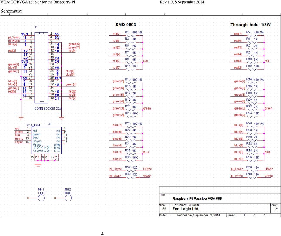
4 Schematic: 4
5 Parts: J1: Female connector 2x20 pins, 0.1 pitch, straight, through hole. J2: Female D-sub 15 pins, angled, VGA pin pattern. I don t know in how far all VGA connectors have the same footprint. I used a VGA connector from Farnell: (AMPHENOL L77HDE15SD1CH4R). Rx: Resistor 1/8W 1%, values as in schematic. Installation Run rpi-update. Copy the file dt-blob-dpi.bin to boot partition of sdcard, renaming it to dt-blob.bin (The file is part of the git-hub database download: setup/dt-blob-dpi.bin). Don t forget that the dt-blob.bin will disable all GPIOs 2-21 for any other use. Thus if you switch back to HDMI you might also want to give the dt-blob.bin file a different name. Add this to config.txt enable_dpi_lcd=1 display_default_lcd=1 You should now be able to boot with VGA resolution on VGA connector. You can change resolution with, e.g. dpi_group=2 dpi_mode=82 (for 1080p60. ) Or: dpi_group=2 dpi_mode=86 (for 1366x768@60) You should notice that these settings are identical to the HDMI settings. The DPI interface (which we use to make the VGA signal) can work in different colour modes. The default mode is 666 (6 Red, 6 Green, 6 Blue colours). Other supported formats are: 565 (5 Red, 6 Green, 5 Blue colours) and 888 (8 Red, 8 Green, 8 Blue colours). Also there are different ways in which the 666 and 565 colours bits can be output on the GPIO line. Please see the table below. Mode RGB bits GPIO You select the mode using: dpi_output_format=x (X in range 1..7) The VGA adaptor PCB is designed up for mode 5. 5

6 Assembly: First mount all the resistors, then the connectors. Make sure you enter the connectors from the right side! The connectors are at the same side as the surface mount resistors. I have made a colour diagram to indicate where the resistors go as the silkscreen was un readable on my PCBs.: SMD side (And connector side). Through-hole side: Red = 499 Ohm Orange = 1K Ohm Yellow = 2K Ohm Green = 4K Ohm Blue = 8K Ohm Purple = 16k Ohm White = Ohm 6

HARDWARE MANUAL. BrightSign HD120, HD220, HD1020. BrightSign, LLC. 16795 Lark Ave., Suite 200 Los Gatos, CA 95032 408-852-9263 www.brightsign.
 HARDWARE MANUAL BrightSign HD120, HD220, HD1020 BrightSign, LLC. 16795 Lark Ave., Suite 200 Los Gatos, CA 95032 408-852-9263 www.brightsign.biz TABLE OF CONTENTS OVERVIEW... 1 Block Diagram... 2 Ports...
Pololu DRV8835 Dual Motor Driver Shield for Arduino
 Pololu DRV8835 Dual Motor Driver Shield for Arduino Pololu DRV8835 Dual Motor Driver Shield for Arduino, bottom view with dimensions. Overview This motor driver shield and its corresponding Arduino library
RGB for ZX Spectrum 128, +2, +2A, +3
 RGB for ZX Spectrum 128, +2, +2A, +3 Introduction... 2 Video Circuitry... 3 Audio Circuitry... 8 Lead Wiring... 9 Testing The Lead... 11 Spectrum +2A/+3 RGB Differences... 12 Circuitry Calculations...
DKWF121 WF121-A 802.11 B/G/N MODULE EVALUATION BOARD
 DKWF121 WF121-A 802.11 B/G/N MODULE EVALUATION BOARD PRELIMINARY DATA SHEET Wednesday, 16 May 2012 Version 0.5 Copyright 2000-2012 Bluegiga Technologies All rights reserved. Bluegiga Technologies assumes
HARDWARE MANUAL HD222, HD1022. BrightSign, LLC. 16780 Lark Ave., Suite B Los Gatos, CA 95032 408-852-9263 www.brightsign.biz
 HARDWARE MANUAL HD222, HD1022 BrightSign, LLC. 16780 Lark Ave., Suite B Los Gatos, CA 95032 408-852-9263 www.brightsign.biz 1 TABLE OF CONTENTS Overview... 1 Block Diagram... 2 HD222... 3 HD1022... 4 Hardware
Best Practices in PCB Design: Exporting Gerber Files
 Page 1 of 5 Improve your ni.com experience. Login or Create Document Type: Tutorial NI Supported: Yes Publish Date: Mar 4, 2009 Best Practices in PCB Design: Exporting Gerber Files Overview This document
Switch board datasheet EB007-00-1
 Switch board datasheet EB007-00-1 Contents 1. About this document... 2 2. General information... 3 3. Board layout... 4 4. Testing this product... 5 5. Circuit description... 6 Appendix 1 Circuit diagram
Technical description MX-1 VB Edge
 1 (7) Technical description MX-1 VB Edge 2 (7) Table of Contents 1 General description...3 2 Connectors...4 3 ON/OFF operation...5 4 Power...5 5 LED indicators...6 6 Enclosure...6 7 Mounting...6 8 and
How to connect to a Class II router using a mobile-phone data cable specifically for Solwise & Safecom routers
 USB to router s serial port How to connect to a Class II router using a mobile-phone data cable specifically for Solwise & Safecom routers by Neo at RouterTech.Org Introduction Routers based on the AR7RD/AR7WRD
Quick Start Guide. The Raspberry Pi Single Board Computer. Source: Raspberry Pi & Wiki
 Quick Start Guide The Raspberry Pi Single Board Computer Source: Raspberry Pi & Wiki Chapter 1: RPi Hardware Basic Setup Typical Hardware You Will Need While the RPi can be used without any additional
RC2200DK Demonstration Kit User Manual
 Demonstration Kit User Manual Table of contents TABLE OF CONTENTS... 1 QUICK INTRODUCTION... 2 INTRODUCTION... 3 DEMONSTRATION BOARD... 4 POWER SUPPLY SECTION... 5 RS-232 INTERFACE... 6 CONNECTORS... 7
An0067. Cable-set Reference Guide. Rev. 2.0 - December 2007 - ETH_An0067_USM20-2007- 12
 An0067 Cable-set Reference Guide Rev. 2.0 - December 2007 - ETH_An0067_USM20-2007- 12 2 Introduction Disclaimer The information in this manual has been carefully checked and is believed to be accurate.
MONOCHROME RGB YCbCr VIDEO DIGITIZER
 Active Silicon SNAPPER-PMC-8/24 MONOCHROME RGB YCbCr VIDEO DIGITIZER High quality analogue video acquisition board with square pixel sampling for CCIR, EIA (RS-170) standards, and nonstandard video formats.
Kit for TLM051 monitor
 1 (5) 1 GENERAL DESCRIPTION The is an operating monitor unit with or without loudspeaker. The 1W mono audio amplifier sent its output signal to the PCB ø 3,5 mm stereo jacket and one board connectors.there
MANUAL FOR RX700 LR and NR
 MANUAL FOR RX700 LR and NR 2013, November 11 Revision/ updates Date, updates, and person Revision 1.2 03-12-2013, By Patrick M Affected pages, ETC ALL Content Revision/ updates... 1 Preface... 2 Technical
3.2 inch QVGA TFT Color LCD User s Guide Version 1 & 2
 3.2 inch QVGA TFT Color LCD - User s Guide 3.2 inch QVGA TFT Color LCD User s Guide Version 1 & 2 Give graphics and to your application! EA2-USG-0701 v2.1 Rev A 3.2 inch QVGA TFT Color LCD - User s Guide
HARDWARE MANUAL. BrightSign XD230, XD1030, XD1230. BrightSign, LLC. 16780 Lark Ave., Suite B Los Gatos, CA 95032 408-852-9263 www.brightsign.
 HARDWARE MANUAL BrightSign XD230, XD1030, XD1230 BrightSign, LLC. 16780 Lark Ave., Suite B Los Gatos, CA 95032 408-852-9263 www.brightsign.biz 1 TABLE OF CONTENTS Overview... 1 Block Diagram... 2 XD230...
Connecting Retro or Vintage Computers to a PC Monitor.
 Connecting Retro or Vintage Computers to a PC Monitor. A technical briefing by J. S. Technology. Introduction. Home computing in the 1980s was just starting to bloom. There was a realisation that the science
KiCad Step by Step Tutorial
 KiCad Step by Step Tutorial Copyright 2006 David Jahshan: kicad at iridec.com.au Copyright: Please freely copy and distribute (sell or give away) this document in any format. Send any corrections and comments
SYSTEM 45. C R H Electronics Design
 SYSTEM 45 C R H Electronics Design SYSTEM 45 All in one modular 4 axis CNC drive board By C R Harding Specifications Main PCB & Input PCB Available with up to 4 Axis X, Y, Z, & A outputs. Independent 25
Wireless Security Camera
 Wireless Security Camera Technical Manual 12/14/2001 Table of Contents Page 1.Overview 3 2. Camera Side 4 1.Camera 5 2. Motion Sensor 5 3. PIC 5 4. Transmitter 5 5. Power 6 3. Computer Side 7 1.Receiver
Color Mark Sensor with Red or Green LED E3S-VS
 Color Mark Sensor with Red or Green LED Rugged IP67 Color Mark Sensor 1 ms response time Detects a wide variety of color marks PNP or NPN output ls Light-on/ Dark-on operation, wire selectable Vertical
MODULE BOUSSOLE ÉLECTRONIQUE CMPS03 Référence : 0660-3
 MODULE BOUSSOLE ÉLECTRONIQUE CMPS03 Référence : 0660-3 CMPS03 Magnetic Compass. Voltage : 5v only required Current : 20mA Typ. Resolution : 0.1 Degree Accuracy : 3-4 degrees approx. after calibration Output
Prototyping Printed Circuit Boards
 Prototyping Printed Circuit Boards From concept to prototype to production. (HBRC) PCB Design and Fabrication Agenda Introduction Why PCBs? Stage 1 Understanding the rules Stage 2 Planning the board. Stage
ASP-DTH. DVI & Audio to HDMI Converter. User Manual. Manual Number: 100901
 ASP-DTH DVI & Audio to HDMI Converter User Manual Manual Number: 100901 Safety and Notice The ASP-DTH DVI & Audio to HDMI Converter has been tested for conformity to safety regulations and requirements,
Advanced Data Capture and Control Systems
 Advanced Data Capture and Control Systems Tronisoft Limited Email: [email protected] Web: www.tronisoft.com RS232 To 3.3V TTL User Guide RS232 to 3.3V TTL Signal Converter Modules P/N: 9651 Document
Uneeda Audio Universal Pad Board
 Uneeda Audio Universal Pad Board Sometimes you need a fixed attenuator when you are designing a sound system. Sometimes this is to force a microphone input to accept a line level signal, sometimes it is
How To Use A Ves-0116 Video Splitter With Audio And Video From A Computer Or Tv Aten (Ves-116)
") User Manual VS-0116 Read this guide thoroughly and follow the installation and operation procedures carefully in order to prevent any damage to the units and/or any devices that connect to them. This package
User Manual VS-0116 Read this guide thoroughly and follow the installation and operation procedures carefully in order to prevent any damage to the units and/or any devices that connect to them. This package
Series. Laser air Leddura Lexinus Mensa. 70 inch. Smart innovation! When function matters.
 Leddura Lexinus Mensa Series When function matters. High quality displays suitable for all applications. Stay connected to your audience via the built-in wireless access point for a productive and collaborative
maxon motor maxon motor control EPOS Positioning Controller Cable Starting Set Edition June 2006 part number 302287 Positioning Controller
 control EPOS Positioning Controller Cable Starting Set Edition June 2006 24/1 part number 302287 Positioning Controller Documentation Cable Starting Set 1 Table of contents 1 Table of contents... 2 2 Table
VideoMate V200/V200F Analog Standalone TV Box Start Up Guide
 VideoMate V200/V200F Analog Standalone TV Box Start Up Guide Compro Technology, Inc. www.comprousa.com 1 Table of Contents About This Guide... 3 VideoMate V200/V200F TV Box Contents... 4 Install V200/V200F
DATASHEET. ADAM Arduino Display Adaptor Module. Arduino Compatible Shield P/N: 4Display-Shield-FT843 For the 4D Systems 4DLCD-FT843 Display
 DATASHEET ADAM Arduino Display Adaptor Module Arduino Compatible Shield P/N: 4Display-Shield-FT843 For the 4D Systems 4DLCD-FT843 Display Document Date: 8 th January 2014 Document Revision: 1.0 Uncontrolled
How To Use A Watt Saver On A Microcontroller (Watt Saver) On A Cell Phone Or Mp3 Player
 On A Cell Phone Or Mp3 Player") Watt Saver for a Cell Phone AC Adapter Reference Design Document Number: DRM130 Rev 1, 10/2013 2 Freescale Semiconductor, Inc. Contents Section number Title Page Chapter 1 Introduction 1.1 Overview...5
Watt Saver for a Cell Phone AC Adapter Reference Design Document Number: DRM130 Rev 1, 10/2013 2 Freescale Semiconductor, Inc. Contents Section number Title Page Chapter 1 Introduction 1.1 Overview...5
The $25 Son of a cheap timer This is not suitable for a beginner. You must have soldering skills in order to build this kit.
 The $25 Son of a cheap timer This is not suitable for a beginner. You must have soldering skills in order to build this kit. Micro Wizard has been manufacturing Pinewood Derby timers for over 10 years.
Laboratory 2. Exercise 2. Exercise 2. PCB Design
 Exercise 2. PCB Design Aim of the measurement Introducing to the PCB design Creating a schematic of an analog circuit, making simulations on it and designing a Printed circuit board for it. Keywords Printed
BUILDING INSTRUCTIONS
 etap2hw 38 mm I2C to LCD Interface BUILDING INSTRUCTIONS October 2013 P. Verbruggen Rev 1.01 15-Oct-13 Page 1 Table of Contents Chapter 1 General Information 1.1 ESD Precautions 1.2 Further Supplies 1.3
KiCad Step by Step Tutorial
 KiCad Step by Step Tutorial Copyright 2006 David Jahshan: kicad at iridec.com.au 2011 Update Copyright 2011 Phil Hutchinson Copyright: Please freely copy and distribute (sell or give away) this document
VF2F. USB Flash Disk File-to-file Transfer Vinculum Evaluation Kit. Future Technology Devices International Ltd. Preliminary - Subject to Change
 Future Technology Devices International Ltd. VF2F USB Flash Disk File-to-file Transfer Vinculum Evaluation Kit http://www.vinculum.com Copyright Future Technology Devices International Ltd. 2006 1. Introduction
SYSTEM 4C. C R H Electronics Design
 SYSTEM 4C C R H Electronics Design SYSTEM 4C All in one modular 4 axis CNC drive board By C R Harding Specifications Main PCB & Input PCB Available with up to 4 Axis X, Y, Z, A outputs. Independent 25
XPort Universal Demo Board User Guide
 XPort Universal Demo Board User Guide Part Number 900-563 Revision A September 2009 Copyright and Trademark Contacts 2009 Lantronix. All rights reserved. No part of the contents of this book may be transmitted
Designing a Schematic and Layout in PCB Artist
 Designing a Schematic and Layout in PCB Artist Application Note Max Cooper March 28 th, 2014 ECE 480 Abstract PCB Artist is a free software package that allows users to design and layout a printed circuit
HT-150 Owner s Manual
 HT-150 Owner s Manual 1 x 5 HDMI to HDBaseT Distribution Amplifier PureLink TM 535 East Crescent Avenue Ramsey, NJ 07446 USA Tel: +1.201.488.3232 Fax: +1.201.621.6118 E-mail: [email protected] www.purelinkav.com
Camera Sensor Driver Development And Integration
 Camera Sensor Driver Development And Integration Introduction Camera enables multimedia on phones. It is going to be an important human machine interface, adding to augmented reality possibilities on embedded
Web Site: www.parallax.com Forums: forums.parallax.com Sales: [email protected] Technical: [email protected]
 Web Site: www.parallax.com Forums: forums.parallax.com Sales: [email protected] Technical: [email protected] Office: (916) 624-8333 Fax: (916) 624-8003 Sales: (888) 512-1024 Tech Support: (888) 997-8267
Chapter 1 Hardware and Software Introductions of pcduino
 Chapter 1 Hardware and Software Introductions of pcduino pcduino is a high performance, cost effective mini PC platform that runs PC like OS such as Ubuntu Linux. It outputs its screen to HDMI enabled
SMARTCARD XPRO. Preface. SMART ARM-based Microcontrollers USER GUIDE
 SMART ARM-based Microcontrollers SMARTCARD XPRO USER GUIDE Preface Atmel SMARTCARD Xplained Pro is an extension board to the Atmel Xplained Pro evaluation platform. Atmel SMARTCARD Xplained Pro is designed
UniPi technical documentation REV 1.1
 technical documentation REV 1.1 Contents Overview... 2 Description... 3 GPIO port map... 4 Power Requirements... 5 Connecting Raspberry Pi to UniPi... 5 Building blocks... 5 Relays... 5 Digital Inputs...
SBC8600B Single Board Computer
 SBC8600B Single Board Computer 720MHz TI s Sitara AM3359 ARM Cortex-A8 Microprocessor Onboard 512MByte DDR3 SDRAM and 512MByte NAND Flash UARTs, 2*USB Host and 1*OTG, 2*Ethernet, CAN, RS485, LCD/TSP, Audio,
USER MANUAL VS92A / VS94A / VS98A
 Video Splitter USER MANUAL VS92A / VS94A / VS98A FCC Information This equipment has been tested and found to comply with the limits for a Class B digital device, pursuant to Part 15 of the FCC Rules. These
RS-232 to TTL Converter Cables SuperDroid Robots 2013 www.superdroidrobots.com
 Description: Designed for easy conversion of a RS-232 signals from a computer to TTL signals in order to interface a computer to a microcontroller or similar electronic devices Features: 72-inch in length
X. Dealing with Signature Differences
 X. Dealing with Signature Differences One of the most often asked questions that Tracker users ask is "when is a different signature considered a fault?". Simply put, "what makes a bad signature?". To
VJ 6040 Mobile Digital TV UHF Antenna Evaluation Board
 VISHAY VITRAMON Multilayer Chip Capacitors Application Note GENERAL is a multilayer ceramic chip antenna designed for receiving mobile digital TV transmissions in the UHF band. The target application for
FLYPORT Wi-Fi 802.11G
 FLYPORT Wi-Fi 802.11G System on module 802.11g WIFI - Infrastructure mode - softap mode - Ad hoc mode Microchip PIC 24F 16 bit processor Microchip MRF24WG0MA/MB - Native WiFi 802.11g transceiver - PCB
QT1 Xplained Pro. Preface. Atmel QTouch USER GUIDE
 Atmel QTouch QT1 Xplained Pro USER GUIDE Preface Atmel QT1 Xplained Pro kit is a set of two extension boards that enables evaluation of self- and mutual capacitance mode touch using the Peripheral Touch
XBee USB Adapter Board (#32400)
") Web Site: www.parallax.com Forums: forums.parallax.com Sales: [email protected] Technical: [email protected] Office: (916) 624-8333 Fax: (916) 624-8003 Sales: (888) 512-1024 Tech Support: (888) 997-8267
Web Site: www.parallax.com Forums: forums.parallax.com Sales: [email protected] Technical: [email protected] Office: (916) 624-8333 Fax: (916) 624-8003 Sales: (888) 512-1024 Tech Support: (888) 997-8267
Product Brief. 2.0 microtoled. Intelligent GOLDELOX Display Module. µtoled-20-g2. www.4dsystems.com.au Rev 1.0
 Product Brief 2.0 microtoled Intelligent GOLDELOX Display Module µtoled-20-g2 www.4dsystems.com.au Rev 1.0 MESSAGE FROM THE CEO To our valued customers, Thank you for your interest in 4D Systems and the
Future Technology Devices International Ltd
 Future Technology Devices International Ltd Datasheet UMFT200XD Breakout Modules 1 Introduction UMFT200XD is a USB to I 2 C breakout module The UMFT200XD breakout module utilizes FTDI s FT200XQ IC to convert
Roku BrightSign Compact Hardware Guide
 Roku BrightSign Compact Hardware Guide PCBA: C Version:.1 Saratoga, CA, USA 1 Table of Contents OVERVIEW... 3 PORTS... 5 POWER CONNECTOR... 5 DB9 RS232 CONNECTOR... 5 DB15 SWITCH/LED CONNECTOR... 6 ETHERNET...
USB 2.0 VGA ADAPTER USER MANUAL
 USB 2.0 VGA ADAPTER USER MANUAL CONTENTS INTRODUCTION... 3 FEATURES... 3 SYSTEM REQUIREMENTS... 3 PACKAGE CONTENTS... 3 SUPPORTED COMMON DISPLAY RESOLUTION... 4 TECHNICAL SPECIFICATIONS... 4 INSTALLATION
CH7101A. CH7101A HDMI to VGA Converter GENERAL DESCRIPTION
 Chrontel Brief Datasheet HDMI to VGA Converter FEATURES HDMI Receiver compliant with HDMI 1.4 specification Analog RGB output for VGA with Triple 9-bit DAC up to 200MHz pixel rate. Sync signals can be
HDMI Modulator single DVB-T. High Definition. User Manual
 HDMI Modulator single DVB-T High Definition User Manual HDMI to DVB T Modulator User Manual CONTENTS Page 1. REAR PANEL 3 2. CONNECTING YOUR SYSTEΜ 4 3. FRONT PANEL BUTTONS 4 4. OPERATING INSTRUCTIONS
POCKET SCOPE 2. The idea 2. Design criteria 3
 POCKET SCOPE 2 The idea 2 Design criteria 3 Microcontroller requirements 3 The microcontroller must have speed. 3 The microcontroller must have RAM. 3 The microcontroller must have secure Flash. 3 The
UPS PIco. to be used with. Raspberry Pi B+, A+, B, and A. HAT Compliant. Raspberry Pi is a trademark of the Raspberry Pi Foundation
 UPS PIco Uninterruptible Power Supply with Peripherals and I 2 C control Interface to be used with Raspberry Pi B+, A+, B, and A HAT Compliant Raspberry Pi is a trademark of the Raspberry Pi Foundation
The modular concept of the MPA-3 system is designed to enable easy accommodation to a huge variety of experimental requirements.
 HARDWARE DESCRIPTION The modular concept of the MPA-3 system is designed to enable easy accommodation to a huge variety of experimental requirements. BASE MODULE GO LINE Digital I/O 8 Analog Out AUX 1
RGB - CGA, EGA, HD to VGA Converter ID# 657
 RGB - CGA, EGA, HD to VGA Converter ID# 657 Operation Manual Introduction Features The RGB, CGA, EGA, HD to VGA Converter PCB board is designed for application in Industry and Gaming. Used for the easy
M68EVB908QL4 Development Board for Motorola MC68HC908QL4
 M68EVB908QL4 Development Board for Motorola MC68HC908QL4! Axiom Manufacturing 2813 Industrial Lane Garland, TX 75041 Email: [email protected] Web: http://www.axman.com! CONTENTS CAUTIONARY NOTES...3 TERMINOLOGY...3
Bluetooth + USB 16 Servo Controller [RKI-1005 & RKI-1205]
![Bluetooth + USB 16 Servo Controller [RKI-1005 & RKI-1205]](/thumbs/40/21161302.jpg "Bluetooth + USB 16 Servo Controller [RKI-1005 & RKI-1205]") Bluetooth + USB 16 Servo Controller [RKI-1005 & RKI-1205] Users Manual Robokits India [email protected] http://www.robokitsworld.com Page 1 Bluetooth + USB 16 Servo Controller is used to control up to
Bluetooth + USB 16 Servo Controller [RKI-1005 & RKI-1205] Users Manual Robokits India [email protected] http://www.robokitsworld.com Page 1 Bluetooth + USB 16 Servo Controller is used to control up to
VE02AL / VE05AL / VE02ALR VGA & Stereo Audio CAT5 Extender with Chainable Output
 VE02AL / VE05AL / VE02ALR VGA & Stereo Audio CAT5 Extender with Chainable Output Introduction: VE02AL, VE05AL is designed for VGA +Stereo Audio signal over cost effective CAT5 cable to instead of VGA and
CMOS OV7660 Camera Module 1/5-Inch 0.3-Megapixel Module Datasheet
 CMOS OV7660 Camera Module 1/5-Inch 0.3-Megapixel Module Datasheet Rev 1.0, June 2013 Table of Contents 1 Introduction...2 2 Features...3 3 Key Specifications...4 4 Application...4 5 Pin Definition...6
VS-0202 VS-0204. User Manual
 User Manual VS-0202 VS-0204 Read this guide thoroughly and follow the installation and operation procedures carefully in order to prevent any damage to the units and/or any devices that connect to them.
PCB Design. Gabe A. Cohn. May 2010. Using Altium Designer/DXP/Protel. Electrical Engineering University of Washington
 PCB Design Using Altium Designer/DXP/Protel Gabe A. Cohn May 2010 Electrical Engineering University of Washington Printed Circuit Board Steps 1. Draw schematics 2. Attach footprints for all components
UGLYDATV 0.1 by F5OEO Evariste
 UGLYDATV 0.1 by F5OEO Evariste November 2014 Introduction This documentation describes a solution to use the Raspberry Pi as a main component of a DVB-S modulator. Two modes are available : - Output I/Q
ABB Drives. User s Manual HTL Encoder Interface FEN-31
 ABB Drives User s Manual HTL Encoder Interface FEN-31 HTL Encoder Interface FEN-31 User s Manual 3AUA0000031044 Rev B EN EFFECTIVE: 2010-04-06 2010 ABB Oy. All Rights Reserved. 5 Safety instructions
Product Information S N O. Portable VIP protection CCTV & Alarm System 2
 Product Information S N O Portable VIP protection CCTV & Alarm System 2 G O V E R N M E N T A L S E C U R I T Y S O L U T I VIP KIT Rapid Deployment VIP Protection Kit The VIP KIT has been designed to
Amplifier for Small Magnetic and Electric Wideband Receiving Antennas (model AAA-1B)
") Amplifier for Small Magnetic and Electric Wideband Receiving Antennas (model AAA-1B) 1. Description and Specifications Contents 1.1 Description 1.2 1.2 Specifications 1.3 1.3 Tested parameters in production
Amplifier for Small Magnetic and Electric Wideband Receiving Antennas (model AAA-1B) 1. Description and Specifications Contents 1.1 Description 1.2 1.2 Specifications 1.3 1.3 Tested parameters in production
ARDUINO SEVERINO SERIAL SINGLE SIDED VERSION 3 S3v3 (REVISION 2) USER MANUAL
 USER MANUAL") ARDUINO SEVERINO SERIAL SINGLE SIDED VERSION 3 S3v3 (REVISION 2) USER MANUAL X1: DE-9 serial connector Used to connect computer (or other devices) using RS-232 standard. Needs a serial cable, with at least
ARDUINO SEVERINO SERIAL SINGLE SIDED VERSION 3 S3v3 (REVISION 2) USER MANUAL X1: DE-9 serial connector Used to connect computer (or other devices) using RS-232 standard. Needs a serial cable, with at least
If anything is damaged or missing, contact your dealer.
 User Manual CS-62 Read this guide thoroughly and follow the installation and operation procedures carefully in order to prevent any damage to the units and/or any devices that connect to them. This package
SMEMA Surface Mount Equtpment Manufacturers Association
 SMEMA Surface Mount Equtpment Manufacturers Association SMEMA Mechanical Equipment Interface Standard Introduction The SMEMA machine interface standards were developed to facilitate the interface of equipment
USB to RS-422/485 Serial Adapter
 USB to RS-422/485 Serial Adapter User Manual Ver. 2.00 All brand names and trademarks are properties of their respective owners. Contents: Chapter 1: Introduction... 3 1.1 Product Introduction... 3 1.2
78 Battery Converter HDMI to SDI
 Battery Converter HDMI to SDI 78 Battery Converter HDMI to SDI Blackmagic Battery Converter HDMI to SDI 1 2 3 USB SDI OUT SDI OUT HDMI LOCK Battery Converter HDMI to SDI 1 2 3 HDMI ON BATT OFF 0 10 50
MOTION COORDINATOR MC206X Quick Connection Guide
 I/O Connector 1 Analogue In / Inputs 0-7 5 Way Connector Power /CANbus I/O Connector 2 24V Power / I/O 8-15 I/O Connector 3 WDOG / Ref Encoder / Analogue Outputs USB Serial A Serial B Axes 0-3 Encoder
PolyBot Board. User's Guide V1.11 9/20/08
 PolyBot Board User's Guide V1.11 9/20/08 PolyBot Board v1.1 16 pin LCD connector 4-pin SPI port (can be used as digital I/O) 10 Analog inputs +5V GND GND JP_PWR 3-pin logic power jumper (short top 2 pins
Advanced LED Controller (LED Chaser)
") Advanced LED Controller (LED Chaser) Introduction. Advanced LED controller (also known as LED Chaser) is microcontroller based circuit designed to produce various visual LED light effects by controlling
Advanced LED Controller (LED Chaser) Introduction. Advanced LED controller (also known as LED Chaser) is microcontroller based circuit designed to produce various visual LED light effects by controlling
Chord Limited. Mojo Dac Headphone Amplifier OPERATING INSTRUCTIONS
 Chord Limited Mojo Dac Headphone Amplifier OPERATING INSTRUCTIONS -!1 - Cleaning and care instructions: Mojo requires no special care other than common sense. Spray window cleaner (clear type) may be used
EZmoto V2. Product description Rev. 6 10/01/2014. EZmoto V2 Product description Rev.6 10/01/2014
 EZmoto V2 Product description Rev. 6 10/01/2014 1 Contents 1. Overview... 3 2. Hardware Interface Description... 3 2.1 Main features of the EZmoto... 3 2.2 Hardware block diagram... 4 2.3 Internal Hardware
STUDY OF CELLPHONE CHARGERS
 STUDY OF CELLPHONE CHARGERS Author : Suraj Hebbar Systems Lab, CeNSE,IISc Banglore ABSTRACT This report shows charging nature of different cellphone chargers with different cellphones. Here we took into
Easy Step 1000 Stepper Driver Module
 Easy Step 1000 Stepper Driver Module STEPPER MOTOR DRIVER MODULE Example Connection Diagram 2 The Easy Step 1000 (ES1000) is intended to be the link between a microprocessor and stepper motor. The ES1000
Part Number: 250-1859
 General Applicability 2010 Honda Insight 07- Kia Optima / Forte / Rondo/ 10- Sedona / 12 Soul 10- Hyundai Tucson / Elantra Touring ETC 2012 Accent / Elantra/ Genesis Recommended Tools Safety Tools Gloves,
Cumbria Designs T-1. SSB/CW Filter kit (4.9152MHz) User Manual
 User Manual") Cumbria Designs T-1 SSB/CW Filter kit (4.9152MHz) User Manual CONTENTS 1 INTRODUCTION 2 2 CIRCUIT DESCRIPTION 2 3 ASSEMBLY 2 4 TESTING 4 The Steading Stainton PENRITH Cumbria CA11 0ES UK 1 Introduction
Cumbria Designs T-1 SSB/CW Filter kit (4.9152MHz) User Manual CONTENTS 1 INTRODUCTION 2 2 CIRCUIT DESCRIPTION 2 3 ASSEMBLY 2 4 TESTING 4 The Steading Stainton PENRITH Cumbria CA11 0ES UK 1 Introduction
NXP enables DisplayPort
 HDMI DVI DP VGA NXP enables DisplayPort NXP DisplayPort Level Shifters, Multiplexers and Adapter selection guide DisplayPort is becoming increasingly popular within the computing industry. It is a royalty-free
PCAN-ISA. CAN Interface for ISA. User Manual
 PCAN-ISA CAN Interface for ISA User Manual Products taken into account Product Name Model Item Number PCAN-ISA Single Channel One CAN channel IPEH-002074 PCAN-ISA Dual Channel Two CAN channels IPEH-002075
QUICK INSTALLATION. MSX-E1516 Ethernet digital I/O system 02.04-08/2014
 QUICK INSTALLATION MSX-E1516 Ethernet digital I/O system 02.04-08/2014 Addi-data GmbH Airpark Business Center Airport Boulevard B210 77836 Rheinmünster Germany Tel: +49 7229 1847-0 Fax: +49 7229 1847-200
nanoetxexpress Specification Revision 1.0 Figure 1 nanoetxexpress board nanoetxexpress 26.02.2009 Specification Rev 1.
 nanoetxexpress Specification Revision 1.0 Figure 1 nanoetxexpress board Specification Rev 1.0 Page 1 of 12 Contents Figure 1 nanoetxexpress board...1 1. Introduction...3 2. Module Configuration...4 3.
PCS300 Universal IP Reporting Module V1.0
 PCS300 Universal IP Reporting Module V1.0 Reference and Installation Manual Patents: One or more of the following US patents may apply: 7046142, 6215399, 6111256, 6104319, 5920259, 5886632, 5721542, 5287111,
5inch HDMI LCD User Manual
 5inch HDMI LCD User Manual Features 800 480 high resolution Directly-pluggable into any revision of Raspberry Pi (only except the first generation Pi model B which requires an HDMI cable) Driver is provided
Quick Start Guide for High Voltage Solar Inverter DC-AC Board EVM. Version 1.3
 Quick Start Guide for High Voltage Solar Inverter DC-AC Board EVM Version 1.3 Introduction This document talks about the quick start principles for the high voltage solar inverter DC-AC board. From this
LMU-5000. Hardware and Installation Guide
 LMU-5000 Hardware and Installation Guide Plan The Installation Verify Power, Ground and Ignition. Be sure to check each source (power, ground and ignition) to ensure that the proper signaling exists. This
VFS24/32HDIP. Public Display IP Monitor User Manual
 VFS24/32HDIP Public Display IP Monitor User Manual 2 Contents Before You Begin...4 Side Panel Control buttons...6 Connections...7 OSD Function...7 LCD monitor Mounting Guide...9 Getting started... 10 Power
WHITE PAPER. LVDS Flat Panel Display Interface on Intel Desktop Boards. July 2009 Order Number: E77911-001
 WHITE PAPER LVDS Flat Panel Display Interface on Intel Desktop Boards July 2009 Order Number: E77911-001 Revision History Revision Revision History Date 1.0 Initial release of the LVDS Flat Panel Interface