Roku BrightSign Compact Hardware Guide
|
|
|
- Lee Skinner
- 9 years ago
- Views:
Transcription
1 Roku BrightSign Compact Hardware Guide PCBA: C Version:.1 Saratoga, CA, USA 1

2 Table of Contents OVERVIEW... 3 PORTS... 5 POWER CONNECTOR... 5 DB9 RS232 CONNECTOR... 5 DB15 SWITCH/LED CONNECTOR... 6 ETHERNET... 9 USB... 9 DB15 VGA CONNECTOR... 9 TRIPLE RCA COMPONENT HD VIDEO CONNECTOR /8 AUDIO CONNECTORS HDMI CONNECTOR V SERIAL CONNECTOR POWER USAGE ENVIRONMENTAL MECHANICAL THEORY OF OPERATION POWER SUPPLY RESET PNX8935 CPU BUILT IN FLASH SDRAM SERIAL PORT VIDEO ENCODER AND FILTER HDMI ENCODER AUDIO OUTPUTS ON BOARD LEDS ON BOARD SWITCH RESET SWITCH/GPIO BUTTON: SDHC & SD FLASH SLOT NAND FLASH ETHERNET USB APPENDIX A FLOW CHART: (FOR REPAIR CENTER USE) (1) POWER START (2) POWER LED COMES ON, NO SERIAL PORT OUTPUT GENERAL TROUBLESHOOTING NOTES: ) VTT (1.25V) SHOULD BE HALF OF VDD (2.5V)
.")
3 Overview This hardware reference manual specifies the hardware interfaces on the Brightsign Compact, as well as providing a guide to troubleshoot the hardware of the Brightsign Compact for in-field service. This manual will not describe any software functions. The Brightsign Compact is a device that can be used to drive a variety of HDTV and computer monitors for digital sign and kiosk applications. As well as driving the Video Display, the Compact has many different control interfaces built in to allow the sign to be controlled. There are several different models of Brightsign Compact that Roku sells. This hardware manual will document all the features on the Compact, even though certain models of the Compact may not have every feature. For example, only some models of the Compact have the Ethernet interface. Brightsign

4 Compact Block Diagram

5 Ports On back of the unit: Power plug for 5V power input at 3A 10/100 Ethernet jack HDMI connector Triple RCA jacks for Component Hi-Def output (Y-Pr-Pb). DB15 VGA video connector. Stereo 1/8 mini plugs for audio output On the side of the unit: USB connector GPIO button Reset button On front of the unit: SD & SDHC flash card slot Green Flash Activity LED Green Power LED Red Status/Err LED Yellow Upgrade LED DA15 Female for GPIO, IR in & out, and 3.3V power. DB9 Male RS232 1/8 serial connector (0-5V serial) Note: Unless otherwise specified, Roku recommends that all cable lengths be 10 Meters or less. The customer may be able to use longer cables in specific cases, but the customer must test the cable to see if it will work. Generally higher quality cables with lower capacitances can be run longer than cheaper cables. Power Connector The power connector on our board is rated at 3A. The plug to go into our connector is standard 5.5MM plug, center positive, with a 1.65MM center pin hole. The power is over voltage protected and reverse polarity protected with two 5W 6V zener diodes. Note that we actually supply our board with 5.2V in order to meet the HDMI specification, but we will refer to this voltage in this document as 5V. DB9 RS232 connector RS232 connector is a male DB9. The HD2000 is a DTE device (like a PC). The input to our chip accepts up to +25V and -25V, so it is compatible with standard +12 and -12 volt signaling. The output of our chip is rated at +5.4V and -5.4V typical which exceeds the voltage required by the RS232 specification. The baud rate is 115,200, No parity, 8 data bits, 1 stop bit. No hardware or software flow control. Maximum cable length is 50 Meters, total cable capacitance 2500pF (using lower capacitance cable allows longer than 50 Meters). The TX and RX signal will look like this:
 Note: Unless otherwise specified, Roku recommends that all cable lengths be 10 Meters or less.")
6 The pinout of the DB9 on the REVB HD2000 board is as follows (NC=No Connect): pin Description pin Description 1 NC 2 Receive data into HD Transmit data out of 4 Available 500mA HD Ground 6 NC 7 Optional TX 2 nd channel 8 Optional RX 2 nd channel 9 NC DB15 Switch/LED connector The Switch/Led connector is a DB15 Female. This connector is used to allow the Compact to control external LEDs or other devices requiring 24mA of current or less. Connect the LED outputs to the LED ANODE and connect LED CATHODE to ground. If you want to connect up some other device then the output is capable of sourcing or sinking up to 24mA at 3.3V, but we do have a series resistor of 100 Ohms in each line. This connector also allows connecting up external contact closures to ground. In order to connect a switch, connect one side of the switch to the switch input, and connect the other side of the switch to one of the ground pins on the DB25 connector. Finally the connector can also supply 3.3V at up to 500mA to an external device. The 3.3V output is polyfuse protected and can source up to 500mA. If a Brightsign is driving the inputs on another Brightsign, then you can at most drive 3 inputs from 1 output. Calculations follow showing why this is: The GPIO outputs have 100 Ohm series resistors, the inputs have 1K pullup resistors to 3.3V, and the input threshold on the 541 chips is 2V high, and.8v low. The high voltage is not a problem, but the low voltage can be if there are too many inputs connected to 1 output. Here are the calculations: 1 out driving 1 in: V=3.3*100/( )=0.3 1 out driving 2 in: V=3.3*100/( )= out driving 3 in: V=3.3*100/( )= out driving 4 in: V=3.3*100/( )=0.94 (Too high, so we can only let 1 output drive 3 inputs MAX!)

7 The DB15 female has the following pinout: pin Description pin Description 1 IR Blaster output 2 Ground 3 Button 6 I/O 4 Button 5 I/O 5 Button 3 I/O 6 Ground 7 Button 1 I/O V 500mA 9 Ground 10 Button 7 I/O 11 Ground 12 Button 4 I/O 13 Button 2 I/O 14 Ground 15 Button 0 I/O DA15 female as viewed from the back of Brightsign Compact: Roku makes a button/led/ir board that can be used to demonstrate how the GPIO and IR works. Here is the schematic to that board as an example of how to connect things to the GPIO connector:

8 In this example schematic, we are using a Vishay TSOP39338 IR receiver, which can operate properly on 3.3V. The TSOP39138 will also work. We are using a Honeywell SEP IR Diode as the IR blaster output.

9 Ethernet The Brightsign Compact has a standard RJ45 connector for 10/100 base T Ethernet. Maximum cable length is 100 Meters. The pinout of the RJ45 is as follows: pin Description pin Description 1 TX+ 2 TX- 3 RX+ 4 RC to ground 5 RC to ground 6 RX 7 RC to ground 8 RC to ground USB The Brightsign Compact has a high speed (480 mbit) USB host port. Maximum cable length is 5 Meters. The port has the following pinout: pin Description pin Description 1 VBUS 2 D- 3 D+ 4 Ground DB15 VGA connector The VGA connector is able to output RGB video. The connector has the following pinout: pin Description pin Description 1 RED analog video output 2 GREEN analog video output 3 BLUE analog video output 4 NC 5 Digital ground 6 Analog ground 7 Analog ground 8 Analog ground 9 +5V DDC supply 10 Digital ground 11 NC 12 DDC SDA 13 HSYNC output 14 VSYNC output 15 DDC SCL Triple RCA Component HD video connector The component triple RCA connector is a able to output the following formats: 480P video: Y from Green jack, Pr from Red jack, and Pb from Blue jack. 720P video: Y from Green jack, Pr from Red jack, and Pb from Blue jack.

10 1080i video: Y from Green jack, Pr from Red jack, and Pb from Blue jack. 1/8 Audio connectors The Brightsign Compact has one 1/8 female audio connectors. The connector has a stereo audio signal. The full scale voltage output of the audio is 2V RMS, with no load. The minimum load resistance that should be connected to the audio output is 5K Ohms. The connector is NOT capable of driving headphones directly. If you need to drive headphones, look into our Brightsign Expander module, which can drive 3 sets of 5 Ohm headphones directly. The audio connector has the following pinout: Tip: Left audio Ring: Right audio Base: Ground for audio signal HDMI connector The HDMI connector is used to send digital video and audio to HDMI enabled sink devices. This is the pinout of the HDMI connector: pin Description pin Description 1 TX2p 2 Ground 3 TX2n 4 TX1p 5 Ground 6 TX1n 7 TX0p 8 Ground 9 TX0n 10 TXCp 11 Ground 12 TXCn 13 CEC 14 NC 15 DDC SCL 16 DDC SDA 17 Ground 18 +5V DDC 19 HPD (Hot Plug Detect) 20 Ground 5V Serial connector The HD2000 has a single 1/8 female connector 5V serial access. This port is used to communicate with devices that require 0 and 5V serial signaling. This connector has the following pinout: Tip: Receive data Ring: Transmit data Base: Ground

11 Power usage The power supply on the Brightsign Compact is a 15W 3A power supply. The Brightsign Compact will use approximately 1A of power when playing a 720p or 1080i MPEG2 HD source file. 1A at 5.2V is about 5W. This implies that there is 2A of additional available power that can be used by peripherals connected to the Brightsign Compact. The user should not connect up any combination of peripherals that will exceed 2A draw. If more than 2A is drawn, then the external power supply will shut down due to overcurrent conditions. The unit will not be damaged, but it may cause the unit to reboot or to not operate properly until the overload is removed. This 2A can be shared any way you like on the following connectors. Ethernet About 180mA when transferring data USB 1500mA max (USB spec is 500mA, but we decided to put out more current on the USB connector just like some PCs do, in order to be able to use the Brightsign Expander in some cases without an additional 5V power supply). DB9 5V 500mA DB25 3.3V 500mA HDMI 5V 55mA max Each of 6 LED outputs on DB25 up to 24mA each IR Blaster output Up to 24mA Environmental The Brightsign Compact is designed to be used between the temperatures of 0 to 40C with 90% maximum relative humidity, non-condensing.

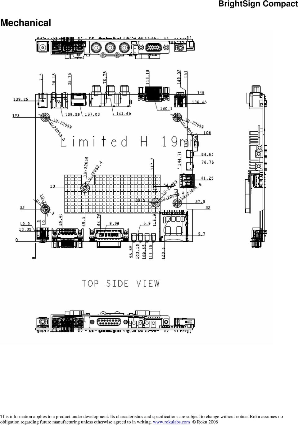
12 Mechanical
13 Theory of operation Power Supply The Brightsign Compact has a five voltages present. These are 5V, 3.3V, 2.5V, 1.8Vand 1.2V. 5V comes in from the power connector and is used directly for USB, the video filter chip.. 3.3V is created from 5V by a Semtech SC196 switching regulator. Similar regulators are used to create 2.5V for the DDR SDRAM, 1.8V for the HDMI chip, and 1.2V for the PNX8935 core voltage. Reset The Brightsign Compact has a Low Voltage Reset circuit made up of a ADM809SAKS. This circuit will hold the RESET_L signal low until a valid 3.3V power is present. PNX8935 CPU The Brightsign Compact has a Philips PNX8935 Multimedia CPU in it. This CPU runs on 3.3V, 2.5V, and 1.2V. The PNX8935 runs from a 27MHz oscillator. The PNX8935 is reset by the signal RESET_L from the low voltage reset circuit going into the RESET_IN pin on the PNX8935. When the RESET_IN pin goes from low to high, then the PNX8935 will boot from NAND flash. Built in Flash The HD2000 contains 3 flash devices. The boot code in the PNX8935 instructs the PNX8935 to continue the boot process by reading additional code from the on board NAND flash. This flash can be updated in the field, either from on the flash slots or USB mass storage. Part of the NAND flash is also used to hold non-volatile parameters. The contents of the boot flash is copied into the SDRAM, then the PNX8935 jumps to the boot code. There is also a serial settings flash that can be used to contain non-volatile settings. The last flash is the Ethernet flash that is used to configure the Ethernet PHY chip. SDRAM The HD2000 contains four DDR SDRAM devices. When the PNX8935 boots, it will copy the code from the NAND flash device into SDRAM, and then execute the code from SDRAM. The SDRAM runs at clock rate 200MHz, with data rate 400MHz. Serial Port The Brightsign Compact has a built in UART that that communicates with the RS232 level shifter. The MAX232 creates valid RS232 voltage levels for the transmit pin by using a capacitive voltage switcher. Video Encoder and Filter The PNX8935 streams decoded video out of the QVCP5L digital port using single data rate clock, and it also streams the same video out of the on board DACs. Analog video comes out of the PNX8935 and is connected to the FMS6203 video filter chip. This chip has a programmable cutoff frequency of either 8MHz, 16MHz or 32MHz, or no filter. Since the video filter has a low impedance output, we can drive both VGA and COMPONENT 75Ohm terminated cables at the same time with no degradation (with the

14 same signal). Some VGA monitors will sync at 720p and 1080i, so only in this case can a picture be displayed on both component and VGA at the same time. HDMI encoder The QVCP5L video is also sent over to the TDA9984B HDMI encoder chip, which drives the HDMI data out of the Brightsign Compact. The HDMI chip is also connected to I2S audio and SPDIF audio, so that audio will be driven out the HDMI connector. The TDA9984A is capable of upscaling video to 1080P. Audio outputs The Brightsign Compact has a single AK4420 high quality audio DAC device. This device take in digital audio signals from the PNX8935 for I2S audio. The AUD_LRCIN signal is the framing signal for the audio, running at the frame rate of the audio source. The frame rate is usually either 44.1KHz or 48KHz. AUD_BITCLK signal is typically 64 times higher than AUD_LRCIN. The AUD_MCLK is usually 4 times faster than the AUD_BITCLK signal. The I2S audio is also routed to the HDMI chip. The audio output from the AK4420 DAC is sent directly to the audio output jack. The AK4420 can drive a 5K load with a 2V RMS signal. On Board LEDs There are 4 on board LEDs, as follows: Green Flash Activity LED, one anytime the SD card is being accessed. Green Power LED, is on any time the board is powered up and not in reset. Yellow Upgrade LED, flashes when the board is being upgraded. Red Status/Err LED On Board Switch The on board switch is connected to a GPIO32. There is a pullup on the button so that GPIO32 is high normally, and it is pulled low when the button is pressed. Reset switch/gpio button: The on board reset switch is connected to GPIO12. Pressing the reset button down will make GPIO12 go low. If you hold the reset button low for approximately 10 seconds, then the board will be hard reset. When the board goes into reset, then the power LED will go out until the reset button is released. SDHC & SD Flash Slot The SDHC & SD flash slot supports SHDC and SD flash cards. Power is controlled by internal mosfets inside the SMSC USB2250 USB Flash controller chip.

15 NAND flash The HD2000 has a built in NAND flash. All the code for the unit is stored on the NAND flash, and it may also be possible to store some content on the NAND flash. The NAND flash is connected to the PCI/XIO bus on the PNX8950. Ethernet 10/100 Base T Ethernet is implemented on the HD2000 by a Realtek RTL8100C PHY controller. This device takes the PNX8950 Ethernet signals and converts them to the differential Ethernet signals. The PHY chip is also connected to an on-board Ethernet magnetic and a RJ45 for cable termination. The DM9161 chip is able to signal to the PNX8950 that its state has changed by toggling the INT_ETH line, which is connected to GPIO11. USB The USB 2.0 High speed host controller is implemented internally inside the PNX8935 SOC chip. There is also a dual over-current protected switch TPS2069 device, which is used to turn on and off power to the USB device, and to detect over-current situations.

16 Appendix A Flow Chart: (for Repair Center Use) (1) Power Start No LEDs on Is the Output power adapter 5V DC? No Replace Power Adapter Is the Voltage of L2 = 5V? Yes Is the Voltage of TP16 3.3V? Yes No No Check D12 & D33 for shorts Check U17, L3, C204 Check U33, Reset circuit U36, R76, D5

17 (2) Power LED comes on, no serial port output No serial port output Is there 2.5V DC at TP18? No Check U18, L5, C212 Yes Yes Is there 1.2V DC at TP20? Yes Is there 16MHz at TP7? Yes Is RESET_L high at pin 1 of U15 after powerup? Is SYS_RES_OUT_N high at C188 after powerup? Check U25 for good program and good solder joints, check SDRAM No No No No Check U20, L6, C223 Check U3, Y3, C186, C187, R134, Nand flash U25 Check U15, U36, S2 Check U3 Check nand contents U25, check nand bus, check sdram

18 (3) Power LED comes on, Red led is out, unit is booting. Serial port tests are in order. Connect a PC to the HD2000 using a null modem cable (Wire up 2-3, 3-2, 5-5). Set the terminal program to ,N,8,1. In order to see all boot messages, hold S1 down while powering the unit on or while using S2 to reset the unit. A) If the serial port is not working, then check U6 and P4. B) Use the dir command to test reading the SD flash card. Use dir USB1: and dir USB2: command to test reading from external USB mass storage devices. If the SD card fails to read, check U12 and the SD socket, and associated resistors. If the USB mass storage reads fail, check U30, U32, and P9. C) Use the videoplay command to test the video and audio outputs, for example videoplay test.mp3 or videoplay test.mpg. If the analog audio fails to work, check U1. Check for the audio master clock on R7, should be MHz or MHz. Check for audio bit clock R9, should be ¼ of the MCLK. Check for LRCLK on R11, should be 44.1KHz or 48KHz. Check for audio data on R13. Check passives on outputs of U1. The voltage output of the audio during this test (fullscale) is 2V RMS, with no load. Check AUD_AVCC5V power supply. D) Connect a Roku Brightsign Compact Test board to the DA15. Run the following script to test the LEDs. If any LED fails to come on, then check U8, U9, U10, U11 and the resistors on the outputs of these. [TBD: Need GPIO LED script for Compact inserted here] E) Connect a Roku Brightsign Compact Test board to the DA15. Run the following script to test the buttons on the test board. Press each button and the screen should show which button is pressed. a led should blink on and off several ight for each button pressed. If any switch fails to read, or is stuck on, then check U7 as well as the resistors and beads on the inputs to U7. This script will test the side panel switch as well as the switches connected to the DA15. [TBD: Need GPIO button script for Compact inserted here] F) Connect a Ethernet cable to a switch. Exit the shell by typing exit and return. Now type ifconfig eth (Use an unused address on your network). The switch should show link on, and you should be able to ping the unit and ping other things on your network. If this does not work, check U5, Y1, T1, P3 and associated passives.

19 General troubleshooting notes: 1) VTT (1.25V) should be half of VDD (2.5V)
 should be")
HARDWARE MANUAL. BrightSign HD120, HD220, HD1020. BrightSign, LLC. 16795 Lark Ave., Suite 200 Los Gatos, CA 95032 408-852-9263 www.brightsign.
 HARDWARE MANUAL BrightSign HD120, HD220, HD1020 BrightSign, LLC. 16795 Lark Ave., Suite 200 Los Gatos, CA 95032 408-852-9263 www.brightsign.biz TABLE OF CONTENTS OVERVIEW... 1 Block Diagram... 2 Ports...
HARDWARE MANUAL. BrightSign XD230, XD1030, XD1230. BrightSign, LLC. 16780 Lark Ave., Suite B Los Gatos, CA 95032 408-852-9263 www.brightsign.
 HARDWARE MANUAL BrightSign XD230, XD1030, XD1230 BrightSign, LLC. 16780 Lark Ave., Suite B Los Gatos, CA 95032 408-852-9263 www.brightsign.biz 1 TABLE OF CONTENTS Overview... 1 Block Diagram... 2 XD230...
HARDWARE MANUAL HD222, HD1022. BrightSign, LLC. 16780 Lark Ave., Suite B Los Gatos, CA 95032 408-852-9263 www.brightsign.biz
 HARDWARE MANUAL HD222, HD1022 BrightSign, LLC. 16780 Lark Ave., Suite B Los Gatos, CA 95032 408-852-9263 www.brightsign.biz 1 TABLE OF CONTENTS Overview... 1 Block Diagram... 2 HD222... 3 HD1022... 4 Hardware
BrightSign Expander Hardware Guide
 Hardware Guide PCBA: Rev C Version: 0.1 Saratoga, CA, USA 1 Table of Contents OVERVIEW... 3 EXPANDER BLOCK DIAGRAM... 4 PORTS... 6 POWER CONNECTOR... 6 OPTICAL SPDIF CONNECTOR... 6 DB25 SWITCH/LED CONNECTOR...
Whale 3. User Manual and Installation Guide. DC Servo drive. Contents. 1. Safety, policy and warranty. 1.1. Safety notes. 1.2. Policy. 1.3. Warranty.
 Whale 3 DC Servo drive User Manual and Installation Guide Contents 1. Safety, policy and warranty. 1.1. Safety notes. 1.2. Policy. 1.3. Warranty. 2. Electric specifications. 2.1.Operation ranges. 3. Connections
RGB for ZX Spectrum 128, +2, +2A, +3
 RGB for ZX Spectrum 128, +2, +2A, +3 Introduction... 2 Video Circuitry... 3 Audio Circuitry... 8 Lead Wiring... 9 Testing The Lead... 11 Spectrum +2A/+3 RGB Differences... 12 Circuitry Calculations...
EZmoto V2. Product description Rev. 6 10/01/2014. EZmoto V2 Product description Rev.6 10/01/2014
 EZmoto V2 Product description Rev. 6 10/01/2014 1 Contents 1. Overview... 3 2. Hardware Interface Description... 3 2.1 Main features of the EZmoto... 3 2.2 Hardware block diagram... 4 2.3 Internal Hardware
STF201-22 & STF201-30
 Description The STF201 is a combination EMI filter and line termination device with integrated TVS diodes for use on downstream USB ports. It is constructed using a proprietary technology that allows passive
Smarthome SELECT Bluetooth Wireless Stereo Audio Receiver and Amplifier INTRODUCTION
 Smarthome SELECT Bluetooth Wireless Stereo Audio Receiver and Amplifier INTRODUCTION The Smarthome SELECT Bluetooth Wireless Stereo Audio Receiver and Amplifier is a multi-functional compact device. It
HT-150 Owner s Manual
 HT-150 Owner s Manual 1 x 5 HDMI to HDBaseT Distribution Amplifier PureLink TM 535 East Crescent Avenue Ramsey, NJ 07446 USA Tel: +1.201.488.3232 Fax: +1.201.621.6118 E-mail: [email protected] www.purelinkav.com
T3 Mux M13 Multiplexer
 T3 Mux M13 Multiplexer User Manual [Type the abstract of the document here. The abstract is typically a short summary of the contents of the document. Type the abstract of the document here. The abstract
The $25 Son of a cheap timer This is not suitable for a beginner. You must have soldering skills in order to build this kit.
 The $25 Son of a cheap timer This is not suitable for a beginner. You must have soldering skills in order to build this kit. Micro Wizard has been manufacturing Pinewood Derby timers for over 10 years.
SABRE Lite Development Kit
 SABRE Lite Development Kit Freescale i.mx 6Quad ARM Cortex A9 processor at 1GHz per core 1GByte of 64-bit wide DDR3 @ 532MHz UART, USB, Ethernet, CAN, SATA, SD, JTAG, I2C Three Display Ports (RGB, LVDS
ASP-DTH. DVI & Audio to HDMI Converter. User Manual. Manual Number: 100901
 ASP-DTH DVI & Audio to HDMI Converter User Manual Manual Number: 100901 Safety and Notice The ASP-DTH DVI & Audio to HDMI Converter has been tested for conformity to safety regulations and requirements,
User Manual PT-E-HIP
 User Manual PT-E-HIP PT-E-HIP User Manual Contents PT-E-HIP-TX Transmitter 1. Introduction 2. How It Connects 3. Features 4. Transmitter Unit Panel Layout PT-E-HIP-RX Receiver 5. Transmitter Unit Panel
SBC8600B Single Board Computer
 SBC8600B Single Board Computer 720MHz TI s Sitara AM3359 ARM Cortex-A8 Microprocessor Onboard 512MByte DDR3 SDRAM and 512MByte NAND Flash UARTs, 2*USB Host and 1*OTG, 2*Ethernet, CAN, RS485, LCD/TSP, Audio,
DK40 Datasheet & Hardware manual Version 2
 DK40 Datasheet & Hardware manual Version 2 IPC@CHIP DK40 Evaluation module Beck IPC GmbH http://www.bcl.de page 1 of 11 Table of contents Table of contents... 2 Basic description... 3 Characteristics...
ARDUINO SEVERINO SERIAL SINGLE SIDED VERSION 3 S3v3 (REVISION 2) USER MANUAL
 USER MANUAL") ARDUINO SEVERINO SERIAL SINGLE SIDED VERSION 3 S3v3 (REVISION 2) USER MANUAL X1: DE-9 serial connector Used to connect computer (or other devices) using RS-232 standard. Needs a serial cable, with at least
ARDUINO SEVERINO SERIAL SINGLE SIDED VERSION 3 S3v3 (REVISION 2) USER MANUAL X1: DE-9 serial connector Used to connect computer (or other devices) using RS-232 standard. Needs a serial cable, with at least
CH7101A. CH7101A HDMI to VGA Converter GENERAL DESCRIPTION
 Chrontel Brief Datasheet HDMI to VGA Converter FEATURES HDMI Receiver compliant with HDMI 1.4 specification Analog RGB output for VGA with Triple 9-bit DAC up to 200MHz pixel rate. Sync signals can be
HDMI Switch USER MANUAL VS481A
 HDMI Switch USER MANUAL VS481A FCC Information This equipment has been tested and found to comply with the limits for a Class B digital device, pursuant to Part 15 of the FCC Rules. These limits are designed
ARM Cortex -A8 SBC with MIPI CSI Camera and Spartan -6 FPGA SBC1654
 ARM Cortex -A8 SBC with MIPI CSI Camera and Spartan -6 FPGA SBC1654 Features ARM Cortex-A8 processor, 800MHz Xilinx Spartan-6 FPGA expands vision processing capabilities Dual MIPI CSI-2 CMOS camera ports,
EVOline Multimedia Modules
 243 EVOline VGA cable EVOline DVI-A cable EVOline DVI-D cable EVOline HDMI cable Cable properties Flame retardant self extinguishing VW-1 Halogen free yes yes yes Colour Black Black Outer diameter 7,2
Product Information S N O. Portable VIP protection CCTV & Alarm System 2
 Product Information S N O Portable VIP protection CCTV & Alarm System 2 G O V E R N M E N T A L S E C U R I T Y S O L U T I VIP KIT Rapid Deployment VIP Protection Kit The VIP KIT has been designed to
STF203-15 THRU STF203-33
 Description The STF03 is a combination EMI filter and line termination device with integrated diodes for use on upstream USB ports. It is constructed using a proprietary technology that allows passive
Modular Video Matrix Switchers and Signal Cards
 AVS800 AVS-4I-DVI AVS-4I-VGA AVS-4I-HDB AVS-4I-HDM AVS1600 AVS-4O-DVI AVS-4O-VGA AVS-4O-HDB AVS-4O-HDM AVS-4I-UNI Product Data Sheet Modular Video Matrix Switchers and Signal Cards AVS800, front view AVS800,
RFS-805. Digital Modulator AV to COFDM. User Manual
 RFS-805 Digital Modulator AV to COFDM User Manual 1. Purpose of use RFS-805 is a digital modulator designed for a processing audio and video signals into COFDM (DVB-T) multiplex. 2. Installation The connections
Advanced Data Capture and Control Systems
 Advanced Data Capture and Control Systems Tronisoft Limited Email: [email protected] Web: www.tronisoft.com RS232 To 3.3V TTL User Guide RS232 to 3.3V TTL Signal Converter Modules P/N: 9651 Document
UniPi technical documentation REV 1.1
 technical documentation REV 1.1 Contents Overview... 2 Description... 3 GPIO port map... 4 Power Requirements... 5 Connecting Raspberry Pi to UniPi... 5 Building blocks... 5 Relays... 5 Digital Inputs...
The basic set up for your K2 to run PSK31 By Glenn Maclean WA7SPY
 The basic set up for your K2 to run PSK31 By Glenn Maclean WA7SPY I am by no means an expert on PSK31. This article is intended to help someone get on PSK31 with a K2. These are the things I did to get
PCAN-MicroMod Universal I/O Module with CAN Interface. User Manual. Document version 2.1.0 (2014-01-16)
") PCAN-MicroMod Universal I/O Module with CAN Interface User Manual Document version 2.1.0 (2014-01-16) Products taken into account Product Name Part number Model PCAN-MicroMod IPEH-002080 with firmware
PCAN-MicroMod Universal I/O Module with CAN Interface User Manual Document version 2.1.0 (2014-01-16) Products taken into account Product Name Part number Model PCAN-MicroMod IPEH-002080 with firmware
How To Sell A Talan
 The TALAN represents state-of-the-art capability to rapidly and reliably detect and locate illicit tampering and security vulnerabilities on both digital and analog telephone systems. Marketing Characteristics
ELAN DIGITAL SYSTEMS LTD. SL232 PC- CARD USER S GUIDE
 ELAN DIGITAL SYSTEMS LTD. LITTLE PARK FARM ROAD, SEGENSWORTH WEST, FAREHAM, HANTS. PO15 5SJ. TEL: (44) (0)1489 579799 FAX: (44) (0)1489 577516 e-mail: [email protected] website: http://www.pccard.co.uk
PolyBot Board. User's Guide V1.11 9/20/08
 PolyBot Board User's Guide V1.11 9/20/08 PolyBot Board v1.1 16 pin LCD connector 4-pin SPI port (can be used as digital I/O) 10 Analog inputs +5V GND GND JP_PWR 3-pin logic power jumper (short top 2 pins
8-Port HDMI Switch USER MANUAL VS0801H
 8-Port HDMI Switch USER MANUAL VS0801H FCC Information This equipment has been tested and found to comply with the limits for a Class B digital device, pursuant to Part 15 of the FCC Rules. These limits
IPG/7700 Hardware Manual SYSTECH. Document number 80-001099-7 Revision A
 IPG/7700 Hardware Manual SYSTECH C O R P O R A T I O N Document number 80-001099-7 Revision A Created 2010, and Protected Under the U.S. Copyright Act of 1976. Copyright 2010, SYSTECH Corporation All Rights
RN-WIFLY-EVAL-UM. WiFly Evaluation Kit. 2012 Roving Networks. All rights reserved. RN-WIFLY-EVAL-UM Version 1.32r 10/9/2012 USER MANUAL
 WiFly Evaluation Kit 2012 Roving Networks. All rights reserved. Version 1.32r 10/9/2012 USER MANUAL OVERVIEW This document describes the hardware and software setup for Roving Networks evaluation kits,
PRELIMINARY USER MANUAL
 KRAMER ELECTRONICS LTD. PRELIMINARY USER MANUAL MODELS: KDS-EN3 HD Video Encoder/Streamer KDS-DEC3 HD Video Decoder P/N: 2900-300375 Rev 1 Contents 1 Introduction 1 2 Getting Started 2 2.1 Achieving the
mdm-mp3 minidirector with MP3 Player
 minidirector with MP3 Player User Manual December 15, 2014 V1.02 Copyright Light O Rama, Inc. 2007, 2008 Table of Contents Introduction... 4 What s in the Box... 4 Hardware Utility Version... 5 Important
HP4000EX Hardware Manual
 INFORMATION TO USER CAUTION RISK OF ELECTRIC SHOCK, DO NOT OPEN! CAUTION: TO REDUCE THE RISK OF ELECTRIC SHOCK, DO NOT REMOVE COVER (OR BACK). NO USER SERVICEABLE PARTS INSIDE. REFER SERVICING TO QUALIFIED
User manual Compact Web PLC WP240 series IEC-line
 User manual Compact Web PLC WP240 series IEC-line update: 09-01-2014 IEC-line by OVERDIGIT overdigit.com 1. General description The WP240 device is a PLC, programmable in IEC61131-3 language using CoDeSys
Arduino Due Back. Warning: Unlike other Arduino boards, the Arduino Due board runs at 3.3V. The maximum. Overview
 R Arduino Due Arduino Due Front Arduino Due Back Overview The Arduino Due is a microcontroller board based on the Atmel SAM3X8E ARM Cortex-M3 CPU (datasheet). It is the first Arduino board based on a 32-bit
Designing VM2 Application Boards
 Designing VM2 Application Boards This document lists some things to consider when designing a custom application board for the VM2 embedded controller. It is intended to complement the VM2 Datasheet. A
Technical Information Jumpers, Connectors and Memory JXM7031 (7031-xxx) MicroATX Motherboard Dual Jasper Forest Processors
 MicroATX Motherboard Dual Jasper Forest Processors") Technical Information Jumpers, Connectors and Memory JXM7031 (7031-xxx) MicroATX Motherboard Dual Jasper Forest Processors Dimension Diagram * = Pin 1 = Card Slots are on.800 centers Notes: All dimensions
Technical Information Jumpers, Connectors and Memory JXM7031 (7031-xxx) MicroATX Motherboard Dual Jasper Forest Processors Dimension Diagram * = Pin 1 = Card Slots are on.800 centers Notes: All dimensions
(2012 10 24) manual_tocomsat duo LITE.indd 20-1 2012-10-24 7:44:57
 manual_tocomsat duo LITE.indd 20-1 2012-10-24 7:44:57") (2012 10 24) manual_tocomsat duo LITE.indd 20-1 2012-10-24 7:44:57 TABLE OF CONTENTS Table of Contents Table of Contents Safety Warning General Information Package Contents & Features Front Panel Rear
(2012 10 24) manual_tocomsat duo LITE.indd 20-1 2012-10-24 7:44:57 TABLE OF CONTENTS Table of Contents Table of Contents Safety Warning General Information Package Contents & Features Front Panel Rear
USER MANUAL V5.0 ST100
 GPS Vehicle Tracker USER MANUAL V5.0 ST100 Updated on 15 September 2009-1 - Contents 1 Product Overview 3 2 For Your Safety 3 3 ST100 Parameters 3 4 Getting Started 4 4.1 Hardware and Accessories 4 4.2
HDMI/DVI to VGA/Component & Audio Break out Converter
 HDMI/DVI to VGA/Component & Audio Break out Converter User Manual (HCV VA) All information is subject to change without notice. All names & trademarks are property of their respective owners. Rev.1002
HDMI Matrix Switch USER MANUAL VM0404H
 HDMI Matrix Switch USER MANUAL VM0404H FCC Information This equipment has been tested and found to comply with the limits for a Class B digital device, pursuant to Part 15 of the FCC Rules. These limits
M68EVB908QL4 Development Board for Motorola MC68HC908QL4
 M68EVB908QL4 Development Board for Motorola MC68HC908QL4! Axiom Manufacturing 2813 Industrial Lane Garland, TX 75041 Email: [email protected] Web: http://www.axman.com! CONTENTS CAUTIONARY NOTES...3 TERMINOLOGY...3
HydraPort 12 Module Connection Ports HPX-1200SL, Brushed Aluminum (FG560-03-SL) HPX-1200BL, Black Anodized (FG560-03-BL)
 HPX-1200BL, Black Anodized (FG560-03-BL)") DATA SHEET HydraPort 12 Module Connection Ports HPX-1200SL, Brushed Aluminum (FG560-03-SL) HPX-1200BL, Black Anodized (FG560-03-BL) Overview With space for up to 12 modules, the HPX-1200 allows you to
DATA SHEET HydraPort 12 Module Connection Ports HPX-1200SL, Brushed Aluminum (FG560-03-SL) HPX-1200BL, Black Anodized (FG560-03-BL) Overview With space for up to 12 modules, the HPX-1200 allows you to
Setup guide. point to point wall plate extenders
 SDS-1002/3 point to point wall plate extenders Setup guide For more information visit our website, or talk to one of our technical team tel: +44 (0) 1306 628264 www.smart-e.co.uk SDS-1002 & 1003 SETUP
TCP/IP MODULE CA-ETHR-A INSTALLATION MANUAL
 TCP/IP MODULE CA-ETHR-A INSTALLATION MANUAL w w w. c d v g r o u p. c o m CA-ETHR-A: TCP/IP Module Installation Manual Page Table of Contents Introduction...5 Hardware Components... 6 Technical Specifications...
RC2200DK Demonstration Kit User Manual
 Demonstration Kit User Manual Table of contents TABLE OF CONTENTS... 1 QUICK INTRODUCTION... 2 INTRODUCTION... 3 DEMONSTRATION BOARD... 4 POWER SUPPLY SECTION... 5 RS-232 INTERFACE... 6 CONNECTORS... 7
MANUAL PC1000R [email protected]
 MANUAL PC1000R [email protected] Features The APart PC1000R is a professional multisource CD/USB/SD card music player, equipped with balanced and unbalanced analog outputs, coaxial and optical digital
MOTION COORDINATOR MC206X Quick Connection Guide
 I/O Connector 1 Analogue In / Inputs 0-7 5 Way Connector Power /CANbus I/O Connector 2 24V Power / I/O 8-15 I/O Connector 3 WDOG / Ref Encoder / Analogue Outputs USB Serial A Serial B Axes 0-3 Encoder
Tele Eye DT Series. Installation Guide. Dialup CCTV Transmitter DT-103G DT-103P DT-103D
 Tele Eye DT Series Dialup CCTV Transmitter DT-103G DT-103P DT-103D Installation Guide Notice: Signal Communications Limited reserves the right to make improvements to the product described in this manual
Pmod peripheral modules are powered by the host via the interface s power and ground pins.
 Digilent Pmod Interface Specification Revision: November 20, 2011 1300 NE Henley Court, Suite 3 Pullman, WA 99163 (509) 334 6306 Voice (509) 334 6300 Fax Introduction The Digilent Pmod interface is used
A+ Guide to Managing and Maintaining Your PC, 7e. Chapter 1 Introducing Hardware
 A+ Guide to Managing and Maintaining Your PC, 7e Chapter 1 Introducing Hardware Objectives Learn that a computer requires both hardware and software to work Learn about the many different hardware components
Bluetooth to Serial Adapter
 Bluetooth to Serial Adapter Third Edition, Oct 2007 Version 3.0 771-BTS1009C3-001 Contents 1.0 Features....P.2 2.0 Package Content....P.2 3.0 Hard Drives Requirement.P.2 4.0 Specifications.P.3 5.0 Pin
Troubleshooting Tips Lifestyle SA-2 & SA-3 Amplifier. Troubleshooting Tips
 Troubleshooting Tips Lifestyle SA-2 & SA-3 Amplifier Refer to the Lifestyle SA-2 & SA-3 Amplifier service manuals, part number 271720 for schematics, PCB layouts and parts lists. Preventative Repair Measures
HDCATS-100. Installation Guide
 HDCATS-100 Installation Guide 1 Contents Description... 3 Features... 4 Application Diagram... 4 Installation... 5 Local HD port... 6 IR Configuration... 7 Serial Data(RS232)... 8 Ethernet Data... 9 Specifications...
User Guide FFFA001106. www.focusrite.com
 User Guide FFFA001106 www.focusrite.com TABLE OF CONTENTS OVERVIEW.... 3 Introduction...3 Features.................................................................... 3 Box Contents...3 System Requirements....4
VS-0202 VS-0204. User Manual
 User Manual VS-0202 VS-0204 Read this guide thoroughly and follow the installation and operation procedures carefully in order to prevent any damage to the units and/or any devices that connect to them.
DMX-K-DRV. Integrated Step Motor Driver + (Basic Controller) Manual
 Manual") DMX-K-DRV Integrated Step Motor Driver + (Basic Controller) Manual DMX-K-DRV Manual page 1 rev 1.33 COPYRIGHT 2007 ARCUS, ALL RIGHTS RESERVED First edition, June 2007 ARCUS TECHNOLOGY copyrights this document.
DMX-K-DRV Integrated Step Motor Driver + (Basic Controller) Manual DMX-K-DRV Manual page 1 rev 1.33 COPYRIGHT 2007 ARCUS, ALL RIGHTS RESERVED First edition, June 2007 ARCUS TECHNOLOGY copyrights this document.
Note monitors controlled by analog signals CRT monitors are controlled by analog voltage. i. e. the level of analog signal delivered through the
 DVI Interface The outline: The reasons for digital interface of a monitor the transfer from VGA to DVI. DVI v. analog interface. The principles of LCD control through DVI interface. The link between DVI
SBC6245 Single Board Computer
 SBC6245 Single Board Computer 400MHz Atmel AT91SAM9G45 ARM 926EJ-STM Microcontroller On Board 128MB Nand Flash plus 128MB DDR2 SDRAM RS232, RS485, Ethernet, USB Host, LCD, Touch Screen, RTC, Supports for
1 Technical Description Lokal-200PC
 1 Technical Description Lokal-200PC 1.1 Overview laptop with in-built accummulator USB connection correlator box internal power supply laptop (if the device has been supplied by F.A.S.T.) BNC aerial connection
Part Number Description Packages available
 Features 3 digital I/O Serial Data output Connects directly to RF Modules Easy Enc / Dec Pairing Function Minimal External Components Required Performs all encoding/decoding of data for Reliable Operation.
Installation Guide. AXIS 2191 Audio Module Sight, Speech and Sound over IP!
 Installation Guide AXIS 2191 Audio Module Sight, Speech and Sound over IP! AXIS 2191 Installation Guide Page 1 of 7 The AXIS 2191 Audio Module The AXIS 2191 Audio Module is an add-on device that provides
NTE2053 Integrated Circuit 8 Bit MPU Compatible A/D Converter
 NTE2053 Integrated Circuit 8 Bit MPU Compatible A/D Converter Description: The NTE2053 is a CMOS 8 bit successive approximation Analog to Digital converter in a 20 Lead DIP type package which uses a differential
Sam440ep-flex User Guide
 Sam440ep-flex User Guide version 0.2 22 May 2009 Please check you local regulations for disposal of electronic devices ACube Systems S.r.l. Via Tabacco, 58-36061 Bassano del Grappa (VI) Italy tel. +39
Modification of an AOR AR-8600 receiver to tune it with a ACECO FC-3002 frequency finder
 Modification of an AOR AR-8600 receiver to tune it with a ACECO FC-3002 frequency finder Matthias DD1US updated June 2 nd 2011 Description of the ACECO FC-3002 unit: The ACECO FC-3002 is a handheld frequency
Banana Pi Open-Source Router Board
 Banana Pi Open-Source Router Board The Banana Pi Router Board is a 300Mbps Wireless N Router with both wired and wireless network connections designed specifically for smart home networking use. With 2T2R
Hardware. NetDCUA5. Documentation. PRELIMINARY This document is subject to change without notice. Version 0.01 (2013-02-22)
") Hardware Documentation Version 0.01 (2013-02-22) PRELIMINARY This document is subject to change without notice. NetDCUA5 About This Document This document describes the hardware of the NetDCUA5. The latest
Hardware Documentation Version 0.01 (2013-02-22) PRELIMINARY This document is subject to change without notice. NetDCUA5 About This Document This document describes the hardware of the NetDCUA5. The latest
Data Acquisition Module with I2C interface «I2C-FLEXEL» User s Guide
 Data Acquisition Module with I2C interface «I2C-FLEXEL» User s Guide Sensors LCD Real Time Clock/ Calendar DC Motors Buzzer LED dimming Relay control I2C-FLEXEL PS2 Keyboards Servo Motors IR Remote Control
VOICE RECORDING SYSTEM ISDN PRI / BRI
 Sense Box VOICE RECORDING SYSTEM ISDN PRI / BRI / Analog SUB-SYSTEM ISDN2, ISDN30 Sense Box USER MANUAL TABLE OF CONTENTS 1. STATUTORY INFORMATION... 3 1.1 SAFETY WARNING... 3 1.2 SAFETY EXTRA LOW VOLTAGE
Cabling Specifications
 APPENDIX A This appendix provides cabling and pinout information for feature cards on the Cisco AS5350XM and Cisco AS5400XM universal gateways. It contains the following sections: 2-Port and 4-Port T1
Web Site: www.parallax.com Forums: forums.parallax.com Sales: [email protected] Technical: [email protected]
 Web Site: www.parallax.com Forums: forums.parallax.com Sales: [email protected] Technical: [email protected] Office: (916) 624-8333 Fax: (916) 624-83 Sales: (888) 512-124 Tech Support: (888) 997-8267
Elettronica dei Sistemi Digitali Costantino Giaconia SERIAL I/O COMMON PROTOCOLS
 SERIAL I/O COMMON PROTOCOLS RS-232 Fundamentals What is RS-232 RS-232 is a popular communications interface for connecting modems and data acquisition devices (i.e. GPS receivers, electronic balances,
VE02AL / VE05AL / VE02ALR VGA & Stereo Audio CAT5 Extender with Chainable Output
 VE02AL / VE05AL / VE02ALR VGA & Stereo Audio CAT5 Extender with Chainable Output Introduction: VE02AL, VE05AL is designed for VGA +Stereo Audio signal over cost effective CAT5 cable to instead of VGA and
Chapter 5 Cubix XP4 Blade Server
 Chapter 5 Cubix XP4 Blade Server Introduction Cubix designed the XP4 Blade Server to fit inside a BladeStation enclosure. The Blade Server features one or two Intel Pentium 4 Xeon processors, the Intel
Video/Cameras, High Bandwidth Data Handling on imx6 Cortex-A9 Single Board Computer
 Video/Cameras, High Bandwidth Data Handling on imx6 Cortex-A9 Single Board Computer The SBC4661 is a powerful 1 GHz Quad Core Cortex-A9 with multiple video ports, quad USB3.0 and dual GigE Ethernet. Using
How to connect to a Class II router using a mobile-phone data cable specifically for Solwise & Safecom routers
 USB to router s serial port How to connect to a Class II router using a mobile-phone data cable specifically for Solwise & Safecom routers by Neo at RouterTech.Org Introduction Routers based on the AR7RD/AR7WRD
DKWF121 WF121-A 802.11 B/G/N MODULE EVALUATION BOARD
 DKWF121 WF121-A 802.11 B/G/N MODULE EVALUATION BOARD PRELIMINARY DATA SHEET Wednesday, 16 May 2012 Version 0.5 Copyright 2000-2012 Bluegiga Technologies All rights reserved. Bluegiga Technologies assumes
- 35mA Standby, 60-100mA Speaking. - 30 pre-defined phrases with up to 1925 total characters.
 Contents: 1) SPE030 speech synthesizer module 2) Programming adapter kit (pcb, 2 connectors, battery clip) Also required (for programming) : 4.5V battery pack AXE026 PICAXE download cable Specification:
CelluLine CGW-TS GSM Cellular Gateway. Installation and Programming Manual
 CelluLine CGW-TS GSM Cellular Gateway Installation and Programming Manual CelluLine CGW-TS GSM Cellular Gateway Installation and Programming Manual CGWTS-M001A Version 1, Release 1, December 2004 NOTICE
ABACOM - netpio. http://www.abacom-online.de/div/setup_netpio.exe
 ABACOM - netpio Download http://www.abacom-online.de/div/setup_netpio.exe The ABACOM netpio board is a 10Mbit network interface designed for measurement and control applications. The board is available
Options for ABB drives, converters and inverters. User s manual FDPI-02 diagnostics and panel interface
 Options for ABB drives, converters and inverters User s manual FDPI-02 diagnostics and panel interface Table of contents Table of contents 3 1. FDPI-02 diagnostics and panel interface Safety..............................................
PCS0100en 02.2008. Persy Control Services B.V. Netherlands
 P-Bus Gateway PBGW2.128 Universal gateway between the P-bus protocol and open standard protocols. The variety of available electrical interfaces on the gateway offers a wide range of possibilities for
M2M 3350 GSM/GPRS Modem User s Manual & Reference Guide Revision 1 June 2007
 M2M 3350 GSM/GPRS Modem User s Manual & Reference Guide Revision 1 June 2007 1999-2007 by Laipac Technology, Inc. All rights reserved The Specifications and information regarding the products in this manual
UPS PIco. to be used with. Raspberry Pi B+, A+, B, and A. HAT Compliant. Raspberry Pi is a trademark of the Raspberry Pi Foundation
 UPS PIco Uninterruptible Power Supply with Peripherals and I 2 C control Interface to be used with Raspberry Pi B+, A+, B, and A HAT Compliant Raspberry Pi is a trademark of the Raspberry Pi Foundation
COPYRIGHT TRADEMARKS
 COPYRIGHT This guide is proprietary to SAMSUNG Electronics Co., Ltd. and is protected by copyright. No information contained herein may be copied, translated, transcribed or duplicated for any commercial
Embedded Display Module EDM6070
 Embedded Display Module EDM6070 Atmel AT91SAM9X35 Based Single Board Computer BY Product Overview Version 1.0 Dated: 3 rd Dec 2013 Table of Contents Product Overview... 2 Introduction... 2 Kit Contents...
Bluetooth UART/RS232 Module
 Introduction BLUEMORE600 is a professional, slim, wireless module ready for integration in brand new or existing electronic products. Based on CSR chipset BC03MM it s fully compatible for Serial Port profiles.
User s Manual of Board Microcontroller ET-MEGA2560-ADK ET-MEGA2560-ADK
 User s Manual of Board Microcontroller ET-MEGA2560-ADK ET-MEGA2560-ADK Because Arduino that is the development project on AVR MCU as Open Source has been published, it is popular and widespread shortly.
SBC8100 Single Board Computer
 SBC8100 Single Board Computer TI OMAP3530 Processor based on 600MHz ARM Cortex-A8 core (for SBC8100) TI DM3730 Processor based on 1GHz ARM Cortex-A8 core (for SBC8100 Plus) Flexible Design with a Tiny
This application note is written for a reader that is familiar with Ethernet hardware design.
 AN18.6 SMSC Ethernet Physical Layer Layout Guidelines 1 Introduction 1.1 Audience 1.2 Overview SMSC Ethernet products are highly-integrated devices designed for 10 or 100 Mbps Ethernet systems. They are
Notice. Reverse engineering and disassembly are prohibited.
 Notice The information in this document is subject to change without notice. Every effort has been made in the preparation of this document to ensure accuracy of the contents, but all statements, information,
AN 17.18. SMSC Design Guide for Power Over Ethernet Applications. 1 Introduction. 1.1 Power Over Ethernet
 AN 17.18 SMSC Design Guide for Power Over Ethernet Applications 1 Introduction 1.1 Power Over Ethernet Power over Ethernet (POE) has emerged as a practical method of providing power to Ethernet devices
Media Gateway Hardware
 Media Gateway Hardware Getting to Know Your Media Gateway E-1 Media Gateway Front Panel E-1 Media Gateway Back Panel E-2 Media Player Front Panel E-2 Media Player Back Panel E-3 MP 2050 Front E-3 MP 2050
Convenient Accessibility
 Conference Table Connectivity Box HDMI / VGA / Mini DisplayPort to HDMI Output with Fast Charge USB Port StarTech ID: BOX4HDECP The BOX4HDECP Automatic Conference Table Connectivity Box features a concealed,