KUSTER ELECTRONIC GAUGES
|
|
|
- Randall Rose
- 10 years ago
- Views:
Transcription
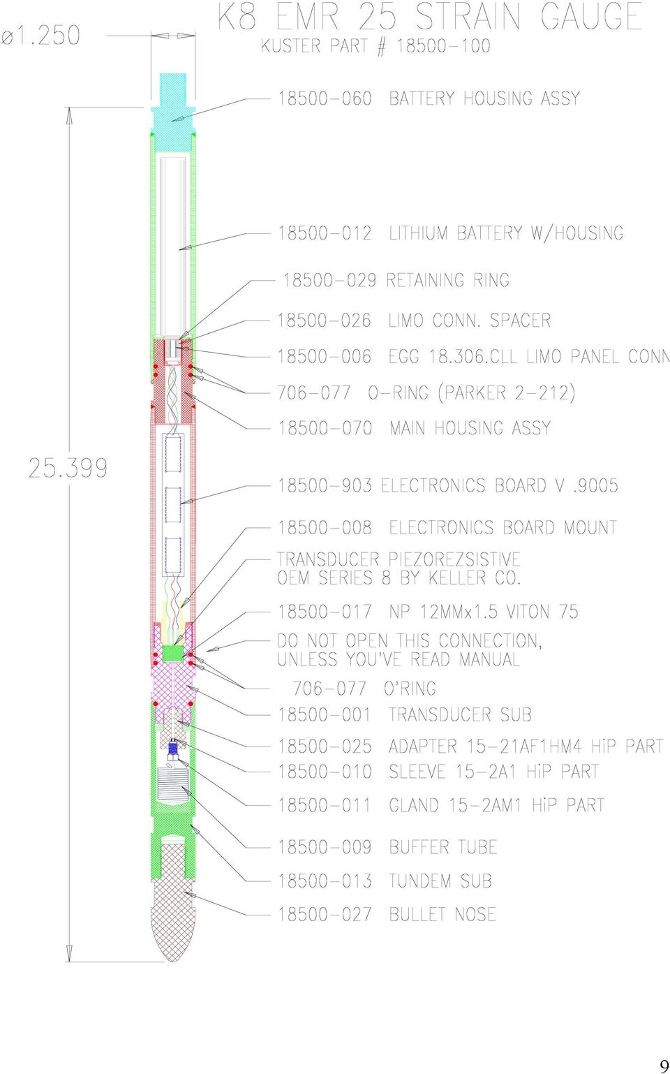
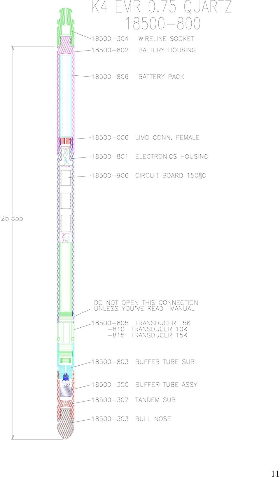
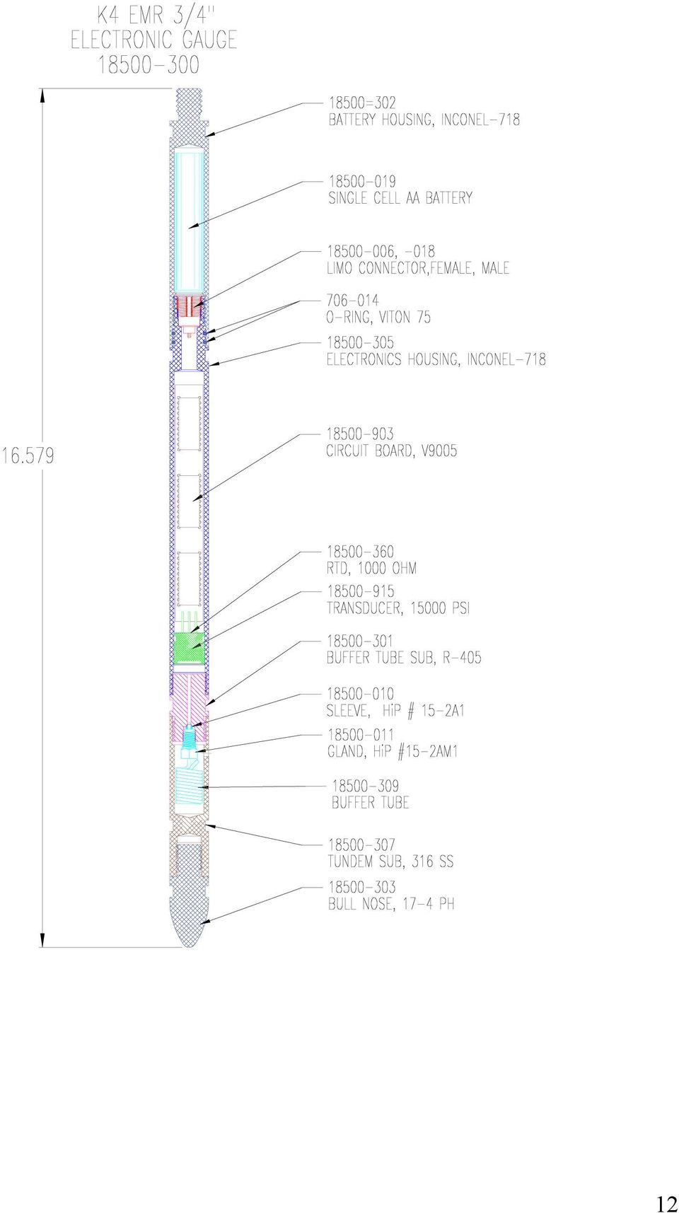
1 Kuster Company 2900 E. 29th Street Long Beach, CA USA Telephone Fax KUSTER ELECTRONIC GAUGES K8 EMR 25, K8 EMR 39, K4 EMR ¾, K4 EMR ¾ QUARTZ SERVICE MANUAL

2 ATTENTION: K8 EMR 25, K8 39 EMR QUARTZ, K4 EMR ¾, K4 EMR ¾ QUARTZ GAUGES: DURING ASSEMBLE/ DISASSEMBLE WRENCHES ARE TO BE PLACED ON THE CLOSEST FLATS. NO PIPE WRENCHES ARE TO BE USED ON KUSTER MEMORY GAUGES. K8 EMR 25, K8 EMR 39 QUARTZ, K4 EMR ¾ QUARTZ GAUGES: IN ORDER TO AVOID TOOL MALFUNCTIONING, O RINGS UNDER THE ELECTRONICS HOUSING SHOULD BE REPLACED STRICTLY ACCORDING THE PROCEDURE, DESCRIBED AT THE END OF THIS MANUAL. WARNING: ALL ELECTRONIC GAUGES: UNDER NO CIRCUMSTANCES IS THE TEMPERATURE RATING OF THE BATTERIES TO BE EXCEEDED. WORK PREPARATION: 1. Make sure that the tool is able to meet the anticipated requirements of the well to be surveyed, i.e. pressure and temperature limitations. 2. Make sure that the battery meets the requirements of the well to be surveyed 3. Check the battery voltage using the supplied battery tester. With the load adapter attached to the DMM, the selector switch to Vdc, and the battery connected to the load adapter. Turn on DMM and read voltage. The battery should be disconnected from the load adapter before 1 minute has elapsed. The load adapter has a 100Ω resistor internally, which simulates the load of the instrument and also serves to wake up the battery under certain conditions. The checking of a battery without the load adapter does not accurately reflect the condition of the battery. The voltage of the battery should in ranges specified in Battery Voltage and Usage Section of this manual. 4. Verify the instrument has a current DWT verification on file. Ideally, the instrument should have been calibrated within the previous year, with a two or four point dead weight check following the last survey. 5. Connect gauge through interface to the computer 6. Program the gauge with desired rate. (See software operational manual for a more detailed explanation of programming options) 7. Apply a bead of Kuster hi-temp thread lube to all threads and across o ring glands 8. Disconnect the buffer tube assembly from transducer sub 9. Drop some oil into the transducer sub until it s full. Never insert syringe or any other device into the transducer port more than 1/8 as damage to transducer may occur. 10. Using oil pump fill buffer tube assembly with a light mineral oil. Don t try too hard pushing the pump lever. Slow, but steady force until oil flows from the end of the tube, that s all you need. 11. Install buffer tube assembly on the gauge 2

3 12. Fill up the tandem sub with the mineral oil. 13. Install tandem sub on the gauge 14. Wipe the oil residues from the gauge and put a piece of scotch tape on the tandem sub hole. Don t forget to take it off before running the tool into the well. 15. Install bull nose Now tool is ready and could be delivered to the well site. AFTER ARRIVAL: 1. Connect the battery and note date and time of connection 2. Verify proper operation of the instrument by viewing 4 flashes on the battery s LED. 3. Install battery housing hand tight and finishing tightening with wrenches. Do not over torque. 4. Connect wireline socket. 5. Remove the tape from the tandem sub put gauge into the well. 6. With the lubricator pressured up, allow the gauge at least 15 minutes within the lubricator to stabilize before running in the hole. 7. If a static gradient is being run, allow at least ten minutes per stop to allow the gauge to stabilize and to provide for a sufficient number of samples to be recorded. Note: the tool should not be pulled in or out in the hole faster than 50 m/min. AFTER THE SURVEY; 1. Pull gauge out of the well. 2. Wash down exterior of tool and wipe dry. 3. Remove battery housing and disconnect the battery (note the time and date). 4. Disconnect tandem sub from the gauge. 5. Disconnect buffer tube assembly 6. Wash down nose of tool, tandem sub and buffer tube assembly with solvent. 7. Flush transducer port with solvent using syringe and allow to drain 8. Flush and fill buffer tube assembly with clean silicone oil and set aside 9. Connect gauge through comm. box to the computer, wait for four LED flashes on comm. box and download data to the hard drive (See software operational manual) 10. Remove old o rings from I/O connector side of the gauge 3

4 11. Wipe clean the threads and O ring surfaces and inspect visually all threads for signs of damage, galling and etc. 12. Install two new O rings under the battery housings 13. Lube threads with Kuster high temp lube 14. Program tool for 2 point DWT 15. Install battery and battery housing 16. Run 2 point DWT 17. Download the data from the gauge. 18. Review, record & file 2 point DWT 19. Fill transducer port with fresh oil and install buffer tube assembly onto it. 20. Install tandem sub and bull nose BATTERY VOLTAGE AND USAGE Given the variety of tests and surveys that exist in the downhole environment a definitive guideline for battery usage is impossible. The technician needs to use a certain amount of judgment on when to use or not to use a particular battery pack. The decision should be based on three things. 1. The length of the test (survey) to be run. 2. The amount of time a battery has been used. 3. The voltage the battery shows on the digital multimeter with the load (battery tester) applied. The circuit board electronics of both the strain and quartz gauges require approximately 3 volts minimum to operate correctly. And the quartz transducer requires 6.5 volts minimum to operate correctly. Since lithium batteries maintain the maximum stated voltage for the useable life of the battery; once the voltage starts to drop their useable life is short indeed. For example: Our AA batteries are rated at 1.5Ah. But this number is taken after 80% of the life has been used. The remaining voltage is approximately 2.5volts. Not enough to operate the gauge properly. 1Ah leaves approximately 3-3.2volts left. Realistically the battery should not be used past 1Ah. Of course this is where the judgment of the operator comes into play. Also don't forget that lithium batteries passivate (go to sleep) and need to be awakened. This can cause the voltage to be much lower than it really is. Wake them up by warming them or using the battery load tester. Recommendation: AA lithium- no load voltage- 3.2volts... Do not use. CC lithium- no load voltage- of 6.9 volts...do not use. Recommendation: AA lithium- with load adapter- 2.9 volts... Do not use. CC lithium- with load adapter- 6.5 volts...do not use. 4

5 LITHIUM OXYHALIDE PRIMARY CELLS Basic Handling Note: With the exception of QTC and PC cells, every Electrochem lithium battery is equipped with an internal safety fuse. These very fast acting fuse elements can be opened with even the slightest short circuit. Therefore, use care in handling these products to prevent any potential short circuit condition. If a cell fuse should open, do not attempt to repair it yourself. Contact Electrochem distributor for assistance. Safety Although every Electrochem lithium battery is designed and manufactured for safe operation, it is important to observe several key points: Never store or operate a battery above its designated maximum temperature. Never store cells of different chemistry, size, age, or discharge depth. Under no circumstances should the terminal cap of a cell be removed. Do not crush, puncture, or attempt to disassemble a cell or battery pack. Never use excessive force, or hammering to free batteries lodged inside any type of housing. Standard industrial safety practices, such as the wearing of eye protection, should always be employed when handling batteries or other high power energy devices. Shipping Electrochem lithium batteries are shipped in full compliance with all rules and regulations governing proper packaging as set forth by the United Nations and enforced by various international agencies. Whenever re-shipping lithium batteries, the customer must ensure that all methods used are in compliance with the latest regulations. Disposal The regulations concerning the disposal of lithium batteries vary widely. Local disposal regulations differ and subject to change. Contact the proper Environmental Agency in your area for questions regarding the disposal of lithium batteries. Specifications 3B1065 Series PMX150 (AA cells) Open circuit voltage at room temperature..3.9v Rated discharge current..20ma Rated capacity Ah Maximum continuous discharge current ma Operating temperature range..-40c to +150C -40F to +302F Weight...15 g Safety fuse....4 A link Lithium weight.0.5 g This product is not restricted under DOT or IATA shipping regulations 5

6 DISASSEMBLE/ ASSEMBLE K8 EMR 25, K8 EMR 39 QUARTZ GAUGES IN ORDER TO CHANGE O RINGS UNDER ELECTRONIC HOUSING The frequency of changing o rings under an electronic housing should be dependent on well fluid types, temperature and gauge usage intensity. With high content H2S we recommend changing these o rings every 6 months or 1000 hours in well, which ever comes first. The frequency of changing o rings under battery housing is up to the tool operator discretion. They should be replaced at the first evidences of wear. All Kuster electronic gauges are furnished with Parker company Viton o rings, which cover the majority of well fluids in the field, however the last decision on which type of o rings to use is up to the operator of the gauge. Wrong choice could lead to tool malfunctioning and denial of warranty. Consult with the o ring manufacturer, if you are not sure that these o rings are suitable for your applications. It is mainly a concern for the well fluids with high content of H2S. Electronic housing disassemble: 1). Looking at the connector that the battery pack plugs into, you should see the snap ring that holds the connector into the housing. Remove this ring. (A small jewelers screwdriver is the recommended tool to use). 2). Attach the removal/install tool and gently pull the connector up out of the housing. Disconnect the removal/install tool from the connector. If a removal/install tool is not available, use the comm. Box connector. 3). Hold the gauge with the connector hanging down. Remove the spacer from the housing. 4). Remove the lower snap ring. Do not let it slip into the upper snap ring groove! 5). Remove the O ring from under the connector s lip. 6). As you unscrew the main housing from the transducer sub feed the connector through the opening in the housing. 7). Remove the main housing from the electronics board-transducer sub assembly. Remove the removal/install tool from the connector. 8). Set the transducer sub /electronics circuit board assembly upright on a clean work bench. (avoid touching any exposed part of the circuit board with your hand). 9). Slide the new O-rings over the connector assembly and circuit board. Push them into the proper grooves in the transducer sub. Reassembly: 1). Feed the removal/install tool through the main housing from the connector opening to the transducer sub opening. 2). Attach the removal/install tool to the lemo connector. Push the spacer over the connector shaft and wrap some tape behind it so it can t come off of the connector when it is fed through the housing. 3). Feed the electronics board/connector back through main housing keeping the slack out of the connector wires. Do not pull on the connector/board assembly. Just use the install tool to guide the connector through the opening. 4). Once the connector/spacer is through the opening remove the install tool and the tape. 5). Push the lower snap ring into the connector opening and seat it on the step in the housing. 6). The spacer rests on top of the snap ring. 7). Replace the O ring under the connector lip and feed the connector and O ring through the opening. Make sure the wires stay below the connector and spacer. The connector can be turned to twist the wires as you feed them into the opening. This makes keeping the wires below the connector easier. 6

7 8). Press on the connector so the upper snap ring grove is visible and install the upper snap ring using a small screwdriver. 7

8 8

9 9
10 10

11 11
12 12
Trillium 40 Axis Spring Tensioner Wire Replacement Instructions
 Trillium 40 Axis Spring Tensioner Wire Replacement Instructions 1 Overview The objective is to replace the broken axis spring tensioner wire. This requires the following tasks: 1. Remove the seismometer
Step-by-step instructions:
 Spark plug thread repair for Ford Triton cylinder heads Step-by-step instructions: Identification Installation Verification Specifically designed and tested for 4.6L, 5.4L, and 6.8L 2 and 4 valve heads,
TRS 090/105 Compressor. Repair Procedures
 TRS 090/105 Compressor Repair Procedures GENERAL FGG All repair and service operations should be performed on a clean bench and with the use of clean tools. Use genuine parts and correct tools for all
3. SEISCO PARTS & SERVICE REMOVAL AND REPAIR GUIDE
 4 3. SEISCO PARTS & SERVICE REMOVAL AND REPAIR GUIDE A. Changing the Control Board B. Replacing a Heating Element C. Thermistor Replacement D. High Limit Switch Replacement E. Level Detector Replacement
Char-Lynn Hydraulic Motor. Repair Information. 10 000 Series. October, 1997
 Char-Lynn Hydraulic Motor October, 1997 Repair Information Geroler Motor Two Speed 001 27 Retainer inside bore of valve plate bearingless motors only 4 15 16 3 6 35 Parts Drawing 25 2 2 1 19 17 36 40 47
INSTALL/REMOVAL INSTRUCTIONS: WINDOW REGULATOR
 REMOVAL/INSTALL OF WINDOW REGULATOR (741-644) Cadillac Escalade, Chevrolet Suburban, Chevrolet Tahoe, GMC Yukon, Chevrolet Silverado, GMC Sierra 2000 05 General Tech Tips: Use painter s tape rather than
Round Housing with Side Ports
 Power Steering Steering Control Unit (SCU) Parts and Repair Information 5 Series Steering Control Units 001 Square Housing with Side Ports Round Housing with Side Ports T E L RP Round Housing with End
INSTALL/REMOVAL INSTRUCTIONS: WINDOW REGULATOR
 REMOVAL/INSTALL OF WINDOW REGULATOR (741-306) Honda Accord 2003 07 General Tech Tips: Use painter s tape rather than duct tape to secure window. It will not damage paint or leave sticky residue. A plastic
2006 JUDY SERVICE GUIDE
 2006 JUDY SERVICE GUIDE For exploded diagram and part number information, refer to the Spare Parts Catalog available on our website at www.rockshox.com. Information contained in this publication is subject
5800 Temperature Sensor Cable Assembly
 5800 Temperature Sensor Cable Assembly Removal and Replacement Instruction Sheet #60-4702-070 Revision D, January 14, 2013 Overview The 5800 has two refrigeration temperature sensors, one attached to the
Char-Lynn Spool Valve Hydraulic Motors. Repair Information. W Series Geroler Motors
 Char-Lynn Spool Valve Hydraulic Motors Repair Information W Series Geroler Motors with Parking Brake 004 Nut Key Ring, Retaining Bearing Ring, Retaining Ring, Retaining Washer (Thick), Pressure Washer,
2006 HEADSHOK Service Video #1
 LEFTY SPEED DLR DAMPING CARTRIDGE This document explains how to properly remove, disassemble, inspect, reassemble and reinstall the Lefty Speed DLR2 damping cartridge. It is a document to be used in conjunction
Service Guide 12/27/03 TESTING, SERVICE & REPAIR GUIDE (For SH Space Heating Models & RA Water Heating Models)
") TESTING, SERVICE & REPAIR GUIDE (For SH Space Heating Models & RA Water Heating Models) WARNING - HIGH VOLTAGE AC electrical circuits are connected to this heater. Do not attempt any service work on the
TESTING, SERVICE & REPAIR GUIDE (For SH Space Heating Models & RA Water Heating Models) WARNING - HIGH VOLTAGE AC electrical circuits are connected to this heater. Do not attempt any service work on the
This is the civilian transfer case with the cooling loop only found in the driven gear half of the front case.
 INTRODUCTION The Transfer case used in the AMG Hummer is a New Venture Gear, model 242. This case has been in use for the H-1/Hummer since the early 1990 s. There have been modifications to the internal
Tri-Homo Style Operation and Maintenance Instructions
 Tri-Homo Style Operation and Maintenance Instructions One Research Drive Stratford, CT 06615 (203) 375-0063 www.sonicmixing.com 1 Installation and Start-up Do not perform following adjustments without
Volkswagen New Beetle 2.0 Liter 4-cyl General, Engine (Engine Code AEG) 17 Engine-Lubrication system (Page GR-17)
 17 Engine-Lubrication system (Page GR-17)") 17 Engine-Lubrication system (Page GR-17) Lubrication system components, removing and installing Oil pan, removing and installing Oil pressure and oil pressure switch, checking Dynamic oil pressure warning
17 Engine-Lubrication system (Page GR-17) Lubrication system components, removing and installing Oil pan, removing and installing Oil pressure and oil pressure switch, checking Dynamic oil pressure warning
12-Volt Negative Ground Installation Instructions
 12-Volt Negative Ground Installation Instructions For Part Number: 1141, 1164, 1165, 1181 CAUTION!!! Before installing, please read the following important information... 1. The Ignitor is designed for
Water Tec of Tucson Water Systems
 Water Tec of Tucson Water Systems Water Filter Owner s Manual Water Tec of Tucson www.water-tec.com 4601 S. 3 RD Avenue Tucson, AZ 85714 (520) 790-1512 Fax (520) 745-0549 1 MAIN COMPONENTS Your water treatment
Section 7 Adjustment, Repair and Replacement
 Section 7 Adjustment, Repair, and Replacement Page 7-1 Section 7 Adjustment, Repair and Replacement Section Contents Page Overview...7-5 Belts Belt Guard Removal/Installation...7-7 Belt Removal/Installation...7-11
For exploded diagram and part number information, refer to the Spare Parts Catalog available on our website at www.rockshox.com.
 For exploded diagram and part number information, refer to the Spare Parts Catalog available on our website at www.rockshox.com. 2 0 0 5 D U K E A I R X C / S L / R A C E S E R V I C E G U I D E Information
INSTALLATION AND OPERATING INSTRUCTIONS For Model GL1 Gate Locks
 Securitron Magnalock Corp. www.securitron.com ASSA ABLOY, the global leader Tel 800.624.5625 [email protected] in door opening solutions INSTALLATION AND OPERATING INSTRUCTIONS For Model GL1 Gate
Drive shaft, servicing
 Volkswagen Passat B6 - Drive shaft, servicing Стр. 1 из 41 40-7 Drive shaft, servicing Drive shafts, overview I - Assembly overview: Drive axle with CV joint VL100 40-7, Drive axle with CV joint VL100,
1998½-2007 Dodge Ram 5.9L Cummins
 9 January 2014 1081130-33 Dodge Cummins Low Fuel Pressure Alarm Light Kit (I-00143) 1 1998½-2007 Dodge Ram 5.9L Cummins LOW FUEL PRESSURE ALARM LIGHT - Installation Manual - Part Number Sequence: 1081130
Waters Corporation. Waters 2690/5 USER & TROUBLESHOOTING GUIDE
 Waters Corporation Waters 2690/5 USER & TROUBLESHOOTING GUIDE Contents 2690/5 Theory Setup procedures. Troubleshooting the 2690/5 User maintenance of the 2690/5 Spare Parts 2 2690/5 Theory 2690/5 Solvent
Ozone Generator Manual
 ENMET Corporation PO Box 979 Ann Arbor, MI 48106-0979 Ozone Generator Manual 80003-118 MCN-282, 05/14/04 Table of Contents 1.0 INTRODUCTION... 1 1.1 Unpack...1 1.2 Check Order...1 1.3 Serial Numbers...1
Micrio WS1 Replacement Wind Speed Sensor and WC1 Replacement Wind Compass Sensor for Raymarine ST50 and ST60 Wind Instruments. Rev 4.
 Micrio WS1 Replacement Wind Speed Sensor and WC1 Replacement Wind Compass Sensor for Raymarine ST50 and ST60 Wind Instruments. Rev 4.1 The Micrio WS1 Wind Speed Sensor and WC1 Compass Sensor are direct
Depending on which elastic support you have you can secure the V2 power unit to the following seat bracket tubes: EXTERNAL DIAMETER 27.
 ASSEMBLY 1 - EPS V2 POWER UNIT (SOLUTION 5) 1.1 - POSITIONING INSIDE THE SEAT TUBE WITH ELASTIC SUPPORT IN THE SEAT BRACKET TUBE Depending on which elastic support you have you can secure the V2 power
TABLE OF CONTENTS. I. TROUBLESHOOTING... 2 - Section 1.01: Common Problems/Solutions... 2
 BAL Accu-Slide System I. Table of Contents TABLE OF CONTENTS I. TROUBLESHOOTING... 2 - Section 1.01: Common Problems/Solutions... 2 II. GETTING STARTED... 5 - Section 2.01: Tools You Will Need... 5 - Section
Polaris 9300 & 9400 Series Robotic Cleaner
 Polaris 9300 & 9400 Series Robotic Cleaner Zodiac Pool Systems, Inc. 1-800-822-7933 www.zodiacpoolsystems.com Regional Extension Instructor ext. Sales Representatives ext. ext. Service Manager ext. ext.
13. REAR WHEEL/BRAKE/SUSPENSION
 13. REAR WHEEL/BRAKE/SUSPENSION 13 3.5~4.5kg-m 8.0~10.0kg-m 0.8~1.2kg-m 3.0~4.0kg-m 2.4~3.0kg-m 3.5~4.5kg-m 6.0~8.0kg-m 13-0 13. REAR WHEEL/BRAKE/SUSPENSION 13 REAR WHEEL/BRAKE/SUSPENSION SERVICE INFORMATION...
For exploded diagram and part number information, refer to the Spare Parts Catalog available on our website at www.rockshox.com.
 For exploded diagram and part number information, refer to the Spare Parts Catalog available on our website at www.rockshox.com. Information contained in this publication is subject to change at anytime
Rebuild Instructions for 70001 and 70010 Transmission
 Rebuild Instructions for 70001 and 70010 Transmission Brinn, Incorporated 1615 Tech Drive Bay City, MI 48706 Telephone 989.686.8920 Fax 989.686.6520 www.brinninc.com Notice Read all instructions before
http://waterheatertimer.org/troubleshoot-rheem-tankless-water-heater.html
 http://waterheatertimer.org/troubleshoot-rheem-tankless-water-heater.html TECHNICAL SERVICE DEPARTMENT Removal, Cleaning, & Reinstallation of the Burner Assembly For models 74 & GT199 Required tools -
2003-2004 SID REAR SERVICE GUIDE
 2003-2004 SID REAR SERVICE GUIDE For exploded diagram and part number information, refer to the Spare Parts Catalog available on our website at www.rockshox.com. Contact your local distributor or visit
Survival Laser SL-001BB Laser Parts Bundle Assembly & Operation Instructions
 Survival Laser SL-001BB Laser Parts Bundle Assembly & Operation Instructions WARNING: READ ALL INSTRUCTIONS AND THE ENCLOSED SAFETY PRECAUTIONS BEFORE ASSEMBLY AND USE Assemble and use these parts ONLY
Cooling system components, removing and installing
 Engine BHW Cooling system components, removing and installing Page 1 / 24 19-1 Cooling system components, removing and installing Warning! When doing any repair work, especially in the engine compartment,
81000 Series Aluminum Gate Valve Installation and Repair Manual
 High Vacuum Valves Leader in Quality and Value 81000 Series Aluminum Gate Valve Installation and Repair Manual Dear Customer, Thank you for choosing HVA as your vacuum valve supplier. Your valve will give
ADDING AN ELECTRIC AUXILIARY FAN TO RADIATOR STACK ON 03 ALPINE COACH
 ADDING AN ELECTRIC AUXILIARY FAN TO RADIATOR STACK ON 03 ALPINE COACH The original design of the 03 Alpine Coaches (and perhaps other years as well) did not include any kind of engine fan engage mechanism
SDX Submersible Depth Transmitter User Manual
 SDX Submersible Depth Transmitter User Manual January 2011 USER INFORMATION Stevens makes no warranty as to the information furnished in these instructions and the reader assumes all risk in the use thereof.
MTX-D, Oil Temperature/Pressure Gauge
 MTX-D, Oil Temperature/Pressure Gauge 1 Mounting and Sensor Installation... 3 1.1 Mounting the Gauge... 3 1.2 Oil Temp Sensor... 3 1.3 Oil Pressure Sensor... 3 2 Wiring... 3 2.1 Main Gauge Wiring... 4
INSTALL/REMOVAL INSTRUCTIONS: WINDOW LIFT MOTOR
 REMOVAL/INSTALL OF WINDOW LIFT MOTOR (742-273) Ford Expedition 1997 2002, Lincoln Navigator 1998 2002, Ford F-150 Super Crew Cab 2001 General Tech Tips: Use painter s tape rather than duct tape to secure
CHROME FRONT BRAKE MASTER CYLINDER KIT
 -J075 REV. 009-0-0 CHROME FRONT BRAKE MASTER CYLINDER KIT GENERAL Kit Number 5-99D, 5-99D Models These Chrome Master Cylinder Kits are designed to replace the original equipment front brake master cylinder
SELF INSTALLATION GUIDE
 Ultrafast Fibre-optic Broadband SELF INSTALLATION GUIDE Gigaclear install permission July2012 v1.0 Before you begin Please make sure you have the correct length of cable. Bear in mind that you may need
DTM04 TANK MONITOR DTM08 TANK MONITOR Dtm12 TANK MONITOR. Installation and Operation Manual
 DTM04 TANK MONITOR DTM08 TANK MONITOR Dtm12 TANK MONITOR Installation and Operation Manual 1 ENGLISH Safety Instructions 2 Features 2-3 Specifications 3 Installation 4-5 Wiring Diagrams 6-7 Warranty 8
Installing the Video Input and TV Tuner Cards in a Compact Computer or a Dual PCI-Slot Tower Computer
 Installing the Video Input and TV Tuner Cards in a Compact Computer or a Dual PCI-Slot Tower Computer This booklet describes how to install the video input and TV tuner cards in a compact Macintosh computer
POSEIDON 2-29, 2-25 & 2-22 POSEIDON 2-29, 2-25 & 2-22 XT
 POSEION 2-29, 2-25 & 2-22 POSEION 2-29, 2-25 & 2-22 XT Repair Manual Index A. Safety precautions 3 B. Technical data 4 C. Structure 5-6. Service / Repair 7-23 E. Tools 24 F. Function 25-26 G. Electric
Joplin Rebuild Instructions
 Joplin Rebuild Instructions This is a step by step list of instruction on how to rebuild the Crankbrothers Joplin post. It may not always be required to completely tear-down the post to do the work needed
PTU Series Ultrahigh-Purity Pressure Transducers
 PTU Series UltrahighPurity Pressure Transducers User s Manual The Swagelok PTU series pressure transducer provides electronic monitoring of system pressure for ultrahighpurity applications. The PTU series
TUTORIAL. REbUILdING. front CALIpER O-RING CONVERSION CORVETTE 1965-82. Part #: HT-1
 Part #: HT-1 1965-82 CORVETTE O-RING CONVERSION front CALIpER REbUILdING TUTORIAL Choosing a Brake Caliper Rebuild Kit Standard Lip Seals vs. O-Ring Seals Lip seal design seals are used on 1965-1982 Corvette
GENUINE PARTS INSTALLATION INSTRUCTIONS
 GENUINE PARTS INSTALLATION INSTRUCTIONS 1. DESCRIPTION: Auto-Dimming Mirror Kit with Compass and HomeLink 2. APPLICATION: Titan 3. PART NUMBER: 999L1 WS000 4. KIT CONTENTS: Item Qty Description Service
ENGINE FUEL FUEL FILTER... FUEL HEATER... INJECTOR... SUPPLY PUMP... COMMON RAIL... FUEL PRESSURE LIMITTER...
 FUEL FILTER............................ FUEL HEATER.......................... INJECTOR.............................. SUPPLY PUMP.......................... COMMON RAIL.......................... FUEL PRESSURE
Clif Mock. True-Cut C21/C22 Isokinetic Sampler. User Manual. Manual No. 9104500142, Rev. B
 Clif Mock True-Cut C21/C22 Isokinetic Sampler User Manual Manual No. 9104500142, Rev. B 2004 NuFlo Technologies, Inc. All information contained in this publication is confidential and proprietary property
CappController Pipette Controller. Operation Manual Version: 1.2. www.capp.dk
 CappController Pipette Controller Operation Manual Version: 1.2 www.capp.dk skal vises her. Table of Content 1. Safety Precautions... 1 2. General Description... 2 3. Getting Started... 4 3.1. Recharging
SIG 556 Match Sear/Hammer Installation
 SIG 556 Match Sear/Hammer Installation ShootingSight LLC 2012 Safety Warning Always verify your firearm is unloaded before working on it. These instructions are meant as a supplemental guide to an armorer
AXLE SHAFTS - FRONT. 1998 Pontiac Bonneville MODEL IDENTIFICATION DESCRIPTION & OPERATION TROUBLE SHOOTING REMOVAL & INSTALLATION
 AXLE SHAFTS - FRONT 1998 Pontiac Bonneville 1998-99 DRIVE AXLES FWD Axle Shafts - Cars - "C", "G" & "H" Bodies GM Aurora, Bonneville, Eighty Eight, LeSabre, LSS, Park Avenue, Regency, Riviera MODEL IDENTIFICATION
Bubble King. User Manual
 Bubble King User Manual TABLE OF CONTENTS 1. Before You Begin... 3 What Is Included... 3 Unpacking Instructions... 3 Claims... 3 Text Conventions... 3 Icons... 3 Document Information... 3 Product at a
Portable Air Conditioner
 Portable Air Conditioner Owner's Manual Model:3 in 1 12,000 Btu/h Series 3 Please read this owner s manual carefully before operation and retain it for future reference. CONTENTS 1. SUMMARY...1 2. PORTABLE
Owner s Manual. Models: 2S5P & 3S5P OPERATION AND MAINTENANCE OF SELF-PRIMING CENTRIFUGAL TRASH PUMPS PEDESTAL DRIVE
 Owner s Manual Models: 2S5P & 3S5P OPERATION AND MAINTENANCE OF SELF-PRIMING CENTRIFUGAL TRASH PUMPS PEDESTAL DRIVE WARNING!! Installation & Operating Instructions Self-Priming Centrifugal Pump DO NOT
Figure 2 The fan and shroud also needs to be removed for access to the four a/c compressor bolts and removal of the compressor from the top.
 Here are some pictures to show what s required when replacing the A/C compressor, expansion valve and receiver/drier on a 2001 Volvo V70. Even if you don t replace these A/C parts these pictures can help
Class 5 to 7 Truck and Bus Hydraulic Brake System
 Class 5 to 7 Truck and Bus Hydraulic Brake System Diagnostic Guide 1st Edition * 5+0 Important Service tes The information in this publication was current at the time of printing. The information presented
Juice Box Stages 1&2 135&335 Installation Guide 5/10/08
 Tools Required: 8mm socket or nut driver Small flat head screwdriver Electrical tape, masking tape, or shrink tube Pep talk: Although the install looks daunting at first, once you get the learning curve
ZAPPY 3 OWNER S MANUAL. Read this manual completely before riding your Electric ZAPPY 3.
 ZAPPY 3 OWNER S MANUAL Read this manual completely before riding your Electric ZAPPY 3. TECHNICAL INFORMATION Model No. : ZAPPY 3 Product size Type of motor Motor power Battery type Battery Charger Charging
site monitoring Kit Site Monitoring Kit User Manual we prove it.
 site monitoring Kit 1 User Manual Site Monitoring Kit User Manual we prove it. 2 site monitoring Kit Content 1. Introduction 3 2. Content of the Site Monitoring Kit 4 3. Preparation 6 1. Positioning of
BETTIS CONVERSION INSTRUCTIONS TO CONVERT HD SERIES ACTUATORS TO HD-M3, HD-SR-M3 HD-M3HW OR HD-SR-M3HW SERIES PNEUMATIC ACTUATORS
 BETTIS CONVERSION INSTRUCTIONS TO CONVERT HD SERIES ACTUATORS TO HD-M3, HD-SR-M3 HD-M3HW OR HD-SR-M3HW SERIES PNEUMATIC ACTUATORS PART NUMBER: 132581 REVISION: A RELEASE DATE: 24 March 2000 Page 1 of 10
Installation and Operation Manual. Digital Remote Meter for Monitoring System Performance. Version: RM-1
 REMOTE METER TM Installation and Operation Manual. Digital Remote Meter for Monitoring System Performance. Version: RM-1 1098 Washington Crossing Road Washington Crossing, PA 18977 USA www.morningstarcorp.com
IMPACT SPRINKLER TROUBLESHOOTING GUIDE
 RAIN USE AND OPERATION BIRD IMPACT SPRINKLER TROUBLESHOOTING GUIDE The diagrams below depict typical Rain Bird sprinklers with all available controls. Your particular model may have only some of these
Stainless Steel Single and Dual Circulation Kits
 Instruction Sheet P/N 160780 01 Stainless Steel Single and Dual Circulation Kits Introduction The single and dual high-pressure circulation kits allow you to vary and control the circulation rate of coating
TUTORIAL. REbUILdING. REAR CALIpER O-RING CONVERSION CORVETTE 1965-82. Part #: HT-2
 Part #: HT-2 1965-82 CORVETTE O-RING CONVERSION REAR CALIpER REbUILdING TUTORIAL Choosing a Brake Caliper Rebuild Kit Standard Lip Seals vs. O-Ring Seals Lip seal design seals are used on 1965-1982 Corvette
12 Volt 30 Amp Digital Solar Charge Controller
 12 Volt 30 Amp Digital Solar Charge Controller User s Manual WARNING Read carefully and understand all INSTRUCTIONS before operating. Failure to follow the safety rules and other basic safety precautions
Fire Hydrant Troubleshooting
 Fire Hydrant Troubleshooting Pulsation or chatter during opening and flow of water from hydrant. Loose condition in stem at lower valve plate nut. Tighten lower valve plate nut and secure with SS lock
Volkswagen Jetta, Golf, GTI 1999, 2000 2.8 Liter VR6 2V Engine Mechanical, Engine Code(s): AFP 17 Engine-Lubrication (Page GR-17)
: AFP 17 Engine-Lubrication (Page GR-17)") 17 Engine-Lubrication (Page GR-17) Lubrication system components, removing and installing Oil filter housing, disassembling and assembling Oil pan, removing and installing Oil pressure and oil pressure
17 Engine-Lubrication (Page GR-17) Lubrication system components, removing and installing Oil filter housing, disassembling and assembling Oil pan, removing and installing Oil pressure and oil pressure
FUEL CELL CAR SCIENCE KIT ASSEMBLY GUIDE. Battery operation instructions:
 FUEL CELL CAR SCIENCE KIT ASSEMBLY GUIDE Battery operation instructions: 1. The removing and inserting of batteries is to be conducted by the adults only. Unscrew the screw holding the battery pack s cover
OPERATIONS AND MAINTENANCE INFORMATION FOR: THE CANPLAS BACKWATER VALVE THE CHEMTROL BALL SHUT OFF VALVE SUMP PUMPS AND WASTEWATER EJECTOR PUMPS
 OPERATIONS AND MAINTENANCE INFORMATION FOR: THE CANPLAS BACKWATER VALVE THE CHEMTROL BALL SHUT OFF VALVE SUMP PUMPS AND WASTEWATER EJECTOR PUMPS THE LOUISVILLE AND JEFFERSON COUNTY METROPOLITAN SEWER DISTRICT
Fleck 4650. Service Manual INSTALLATION AND START-UP PROCEDURE TABLE OF CONTENTS JOB SPECIFICATION SHEET
 Fleck 4650 Service Manual TABLE OF CONTENTS JOB SPECIFICATION SHEET...1 INSTALLATION AND START-UP PROCEDURE...1 CONTROL VALVE DRIVE ASSEMBLY...2 CONTROL DRIVE ASSEMBLY FOR CLOCK...3 BYPASS VALVE ASSEMBLY...4
Elecraft K3 KPA3 Power Connector Replacement Revision A Review, April 16, 2012 Copyright 2012, Elecraft, Inc. All Rights Reserved
 Introduction Elecraft K3 KPA3 Power Connector Replacement Revision A Review, April 16, 2012 Copyright 2012, Elecraft, Inc. All Rights Reserved The connectors furnishing high current to the KPA3 module
How To Fix A Car With A Carbide Engine
 Section 12 Adjustment, Repair, and Replacement Page 12-1 Section 12 Adjustment, Repair and Replacement Section Contents Page Overview...12-5 Belts Belt Guard Removal/Installation...12-7 Belt Removal/Installation...12-11
IMPORTANT DOCUMENTATION DO NOT DISCARD!
 PART NO.: 6441-263C SERIES GRT 3 JAW PARALLEL GRIPPERS INFORMATION SHEET IMPORTANT DOCUMENTATION DO NOT DISCARD! Use this information sheet to assist with gripper installation and setup. File with maintenance
Installation and Troubleshooting Instructions for Electric Tankless Residential Water Heaters.
 Model Number: Serial Number: Information Manual Installation and Troubleshooting Instructions for Electric Tankless Residential Water Heaters. ATTENTION: IF YOU ARE NOT A LICENSED PLUMBER OR A LICENSED
FPU SYSTEMS OPERATION MANUAL BOH OFFICE MODULE (INCLUDING REPAIR PARTS & SPECIAL TOOL LIST) BOH FPU Field Pack/up Units CHAPTER 5
 BOH FPU Field Pack/up Units CHAPTER 5") FPU SYSTEMS OPERATION MANUAL BOH OFFICE MODULE (INCLUDING REPAIR PARTS & SPECIAL TOOL LIST) BOH FPU Field Pack/up Units CHAPTER 5 UNIT MAINTENANCE INSTRUCTIONS This page was intentionally left blank 0022
FPU SYSTEMS OPERATION MANUAL BOH OFFICE MODULE (INCLUDING REPAIR PARTS & SPECIAL TOOL LIST) BOH FPU Field Pack/up Units CHAPTER 5 UNIT MAINTENANCE INSTRUCTIONS This page was intentionally left blank 0022
INGROUND, ROPED, AND HOLELESS JACK SEAL REPLACEMENT
 D. L. Martin Company INGROUND, ROPED, AND HOLELESS JACK SEAL REPLACEMENT TYPICAL HYDRAULIC JACK HEAD ASSEMBLY 1 TOOLS REQUIRED: 1) Container to hold hydraulic fluid. 2) Clean rags and protective covers
2013 VTech Printed in China 91-009656-000 US
 Rechargeable Power Pack User s Manual 2013 VTech Printed in China 91-009656-000 US INTRODUCTION The Rechargeable Power Pack makes it easier than ever to keep the InnoTab 3 or InnoTab 3S charged and ready
Table of Contents. Overview 1. Pump Disassembly 2. Control Disassembly / Reassembly 7. Pump Reassembly 13. Adjustment Procedures DR Control 19
 Table of Contents Overview 1 Pump Disassembly 2 Control Disassembly / Reassembly 7 Pump Reassembly 13 Adjustment Procedures DR Control 19 Adjustment Procedures DRG Control 20 Adjustment Procedures DFR
Navico-Northstar 2kW JRC Radar Package, Scanner Cable Removal and Replacement
 Navico-Northstar 2kW JRC Radar Package, Scanner Cable Removal and Replacement This work instruction describes the methods and means for which to remove and reinstall optional scanner cable configurations
SERVICE GUIDE For WARN PULLZALL 120v AC &100v AC P/N 685000 & 685001
 SERVICE GUIDE For WARN PULLZALL 120v AC &100v AC P/N 685000 & 685001 REPAIR / REPLACEMENT INSTRUCTIONS TROUBLE SHOOTING GUIDE 986765A2.doc Page 1 of 50 WARNING This guide identifies potential hazards and
HP ProLiant DL380 G6 Carrier-Grade Server Read Before Install
 HP ProLiant DL380 G6 Carrier-Grade Server Read Before Install Carrier-Grade Instructions HP Part Number: AM275-9001A Published: July 2012 Edition: 3 Copyright 2009, 2012 Hewlett-Packard Development Company,
Trace Dissolved Oxygen Sensor
 Instruction Sheet PN 51A-499ATRDO/rev.G September 2010 Model 499A TrDO Trace Dissolved Oxygen Sensor For additional information, please visit our website at www.emersonprocess.com/raihome/liquid/. CAUTION
Overview PARTS LIST. B. Lever mounting base C. Flush handle assembly D. Grey/Blue float stop E. Grey float (Full Flush) F. Flush valve washer
 F. Flush valve washer") Overview READ ENTIRE INSTRUCTIONS BEFORE STARTING INSTALLATION PARTS LIST A. Flush valve B. Lever mounting base C. Flush handle assembly D. Grey/Blue float stop E. Grey float (Full Flush) F. Flush valve
Overview READ ENTIRE INSTRUCTIONS BEFORE STARTING INSTALLATION PARTS LIST A. Flush valve B. Lever mounting base C. Flush handle assembly D. Grey/Blue float stop E. Grey float (Full Flush) F. Flush valve
DIY Wearable Pi with Near-Eye Video Glasses
 DIY Wearable Pi with Near-Eye Video Glasses Created by Ruiz Brothers Last updated on 2015-02-20 09:31:15 AM EST Guide Contents Guide Contents Overview 3D Printing Disassembly Assembly Video Configurations
Doc.No. NDP 192U-02. Electric Pump Controller CE-124P. Instruction Manual
 Doc.No. NDP 192U-02 Electric Pump Controller CE-124P Instruction Manual 1. Parts Name and Function 1) POWER LED Indicate that CE-124P is powered up. 2) START/STOP KEY (SELECTOR KEY) Used to start and stop
2003 ACCORD - Automatic Transmission Removal
 2003 ACCORD - Automatic Transmission Removal Special Tools Required Engine support hanger, A and Reds AAR-T-12566 Engine hanger balancer bar VSB02C000019 Front subframe adapter VSB02C000016 These special
Post Mount Light Installation*
 Post Mount Light Installation* *For the general installation of most Post Mount Spotlights, many vehicles may need slight modifications to these instructions. You will need the following tools: High torque
300 SERIES 331, 332, 333, 344, 356 AND 367 MODELS
 Section: MOYNO 500 PUMPS Page: 1 of 8 Date: March 1, 1998 SERVICE MANUAL MOYNO 500 PUMPS 300 SERIES 331, 332, 333, 344, 356 AND 367 MODELS Mechanical Seal Models Packing Gland Models MODELS DESIGN FEATURES
IMPORTANT SAFETY RULES TO FOLLOW
 WARNING FLOOR & CARPET CLEANER Any piece of equipment can be dangerous if not operated properly. YOU are responsible for the safe operation of this equipment. The operator must carefully read and follow
STEERING SYSTEM - POWER
 STEERING SYSTEM - POWER 1990 Nissan 240SX 1990 STEERING Nissan - Power Rack & Pinion Axxess, Maxima, Pulsar NX, Sentra, Stanza, 240SX, 300ZX DESCRIPTION The power steering system consists of a rack and
Back-Up Camera Installation Guide
 Hz Hz In This Guide: Back-up camera installation requires connecting power wiring to the existing reverse lighting circuit and adding a chassis ground, as well as routing a video signal cable to the front
ELECTRIC BICYCLE OWNER S MANUAL
 ELECTRIC BICYCLE OWNER S MANUAL For Owners of EG Bali 500EX and EG Milan 500EX Electric Bicycle Table of Contents Descriptions: Page Installation Instructions 2 How to install the bicycle out of the box
Service Manual Rol-Lift
 R 2000 Service Manual Rol-Lift Series: T and E Developed by Generic Parts Service This manual is intended for basic service and maintenance of the Rol-Lift pallet jack. The pallet jacks you are servicing
Operation Manual Magic Bowling. Warning Please read this manual carefully before using this machine
 Operation Manual Magic Bowling Warning Please read this manual carefully before using this machine Preface 1. Company profile: Zhongshan star amusement equipment Co., Ltd, ltd, which designs and manufactures
Replacement Instructions. Warning: During this procedure, keep small parts away from children.
 apple ibook G4 Memory Card Replacement Instructions Follow the instructions in this sheet carefully. Failure to follow these instructions could damage your equipment and void its warranty. Note: Written
MIC-WKT and MIC-WKT-IR
 MIC-WKT and MIC-WKT-IR Installation Manual Bosch Security Systems EN Installation and Operation Manual MIC-WKTI and MIC-WKT-IR Installation Manual EN 2 MIC-WKT and MIC-WKT-IR Washer Pump Drive Card Kits