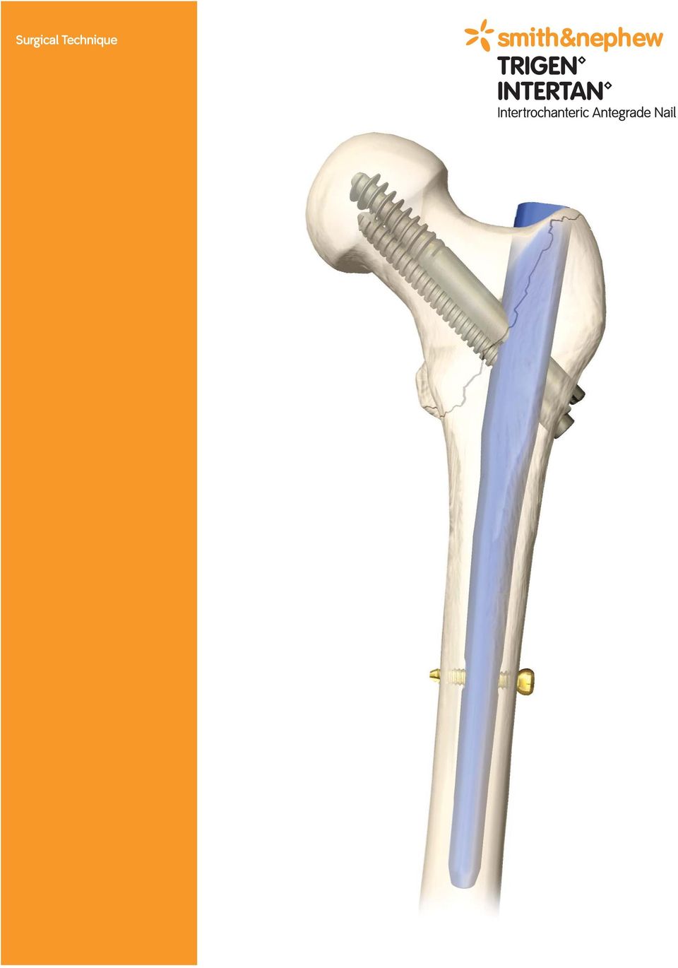
TRIGEN INTERTAN Intertrochanteric Antegrade Nail Surgical Technique. Table of Contents
|
|
|
- Maria Townsend
- 10 years ago
- Views:
Transcription
1 Surgical Technique
2

3 TRIGEN INTERTAN Intertrochanteric Antegrade Nail Surgical Technique As described by: Andreas H. Ruecker, MD Thomas A. Russell, MD Roy W. Sanders, MD Paul Tornetta, MD Table of Contents Features INTERTAN System Case Examples Design Features Nail Specifications Indications Surgical Technique Patient Positioning Incision Entry Point Fracture Reduction Nail Length Measurement Preparation of the Medullary Canal Target Device Assembly Nail Insertion Anteversion Alignment AP Alignment Guide Pin Insertion Lag Screw Measurement Single Lag Screw Insertion Integrated Interlocking Lag Screw Insertion Distal Locking Nail Cap Insertion Nail Extraction Catalog Information Nota Bene The technique description herein is made available to the healthcare professional to illustrate the author s suggested treatment for the uncomplicated procedure. In the final analysis, the preferred treatment is that which addresses the needs of the specific patient. 1

4 Introduction INTERTAN Nails - Designed for Stability The TRIGEN INTERTAN nail was designed as a trochanteric portal intramedullary nail especially shaped for fractures of the proximal femur. The INTERTAN system offers anatomically shaped trapezoidal implants as opposed to conventional circular shaped intramedullary nails. The INTERTAN system offers an integrated interlocking screw option to increase stability and resistance to intra-operative and post-operative femoral head rotation, thus eliminating excessive sliding and the possibility of Z-effect. The INTERTAN screw is a 4th generation intramedullary nail combining the rotational stability of the original RUSSELL-TAYLOR Reconstruction Nail with the enhanced sliding and compression of the IMHS Intramedullary Hip Screw. The INTERTAN system screw utilizes the best of both concepts. The option of a single lag screw device placed in the femoral head is available for rotationally stable proximal femur fractures. Devices in the proximal femur are at their greatest stress levels when the hip is placed through its flexion extension arc (ex: chair rise and climbing stairs). During this event, the trapezoidal shape of the INTERTAN system enhances stability of the implant within the femur. In addition, the integrated interlocking screw configuration imparts rotational stability in the femoral head and neck segment, and offers a greater resistance to cutout. With these features, the INTERTAN system provides an innovative treatment option for proximal femur fractures. 2

5 This next generation nail in the TRIGEN system provides these clear advantages: Implants Additional strength and stability with a unique integrated interlocking screw and trapezoidal nail shape Improved resistance to femoral head rotation and cutout Active compression achieved through a linear motion without rotation Single subtrochanteric lag screw option for stable fractures below the lesser trochanter Preloaded cannulated set screw converts the construct to a fixed angle device The small proximal diameter of the nail promotes preservation of the lateral wall of the greater trochanter and gluteus medius tendon Clothespin tip for stress modulation in the femoral shaft Potential for improved patient mobility and recovery Instrumentation Familiar, easy to use, minimally invasive TRIGEN instrumentation Anti-rotation bar maintains stability during drilling and screw insertion Alignment guides for proper lag screw placement in the femoral neck and head 3

6 INTERTAN System Case Examples Case 1 Preoperative AP Preoperative Lateral Postoperative AP Postoperative Lateral 12 Month AP 12 Month Lateral 4

7 Case 2 Preoperative AP Postoperative AP Postoperative Lateral 5

8 Design Features Two-screw integrated interlocking provides: Improved resistance to femoral head rotation and cutout Active compression achieved through a linear motion without rotation 4 Lateral offset for trochanteric insertion Preloaded cannulated set screw converts construct to a fixed angle device or allows for post operative sliding Figure 8 cross-section to improve resistance of cutout Trapazoidal nail shape provides additional strength and stability in the proximal femur during flexion extension similar to hip stem prosthesis Small proximal diameter of the nail promotes preservation of the lateral wall of the greater trochanter and gluteus medius tendon Distal slot for static or 5mm of dynamization and rotational stability Clothespin tip for stress modulation in the femoral shaft which reduces stiffness that can cause thigh pain and periprosthetic fracture Optional distal diameters for optimal fit in femoral canal 6

9 Implant Specifications 11mm Minor diameter tapers from mm 7.8 mm 32mm 7mm 15.25mm Integrated interlocking screws (sold together) mm mm 28.3mm 16.25mm 18, 20cm 5mm 10, 11.5, 13mm 40mm / 18cm 60mm / 20cm NOTE: These views are not to scale and should be used as a pictorial representation only. 7

10 Implant Specifications continued 16.25mm 28.3mm 15.25mm 2m AP Bow 26-46cm 10, 11.5, 13mm 40mm 20mm 15mm 11mm 32mm Minor diameter tapers from mm Subtrochanteric lag screw mm NOTE: These views are not to scale and should be used as a pictorial representation only. 8

11 Indications INTERTAN nails are indicated for simple long bone fractures; severely comminuted, spiral, long oblique and segmental fractures; nonunions and malunions; polytrauma and multiple fractures; prophylactic nailing of impending pathologic fractures; reconstruction following tumor resection and grafting; bone lengthening and shortening; subtrochanteric fractures; ipsilateral femoral shaft/neck fractures; intertrochanteric fractures; and intracapsular fractures. 9

12 Templates Use the Smith & Nephew Preoperative INTERTAN nail templates to determine the appropriate neck angle, nail length, nail diameter and proper screw length. All INTERTAN nail templates are available with 117% magnification to compensate for radiographic magnification. Please keep in mind that variations in magnification do occur. 110mm 115mm *120mm *125mm 130 Template Lag Screw Centerline 105mm 20mm 100mm 95mm When selecting the appropriate nail size take all aspects of the fracture into consideration. 10mm Top of Nail *70mm *75mm 80mm 85mm 90mm cm mm 15.2mm mm Shaft Diameter Lateral View 10.0mm 11.5mm 13.0mm* A/P View 18cm 20cm* 5.0mm Gold Screw RIGHT LEFT 20 *Special Request Orthopaedics Smith & Nephew, Inc. mm mm Brooks Road Memphis, TN USA 117% Magnification Telephone: For information: Trademark of Smith & Nephew. Reg. US Pat. & TM Off. For orders and order inquiries: / TRIGEN INTERTAN Nail X-ray Template Set Cat. No

13 Patient Positioning Place the patient in the supine position on a fracture or radiolucent table with the unaffected limb extended below the affected limb and trunk. Flex the affected hip 15º-40º. Apply traction through a skeletal traction pin or with the fracture table foot holder. Adjust the affected limb for length and rotation by comparison with the unaffected limb. Check rotation by rotating the C-arm in line with the femoral neck anteversion and then make the appropriate correction. This is best checked by visualizing the femoral anteversion proximally and matching it with the correct rotation of the knee. The lateral decubitus position may be selected in certain fracture configurations at the surgeon s discretion. For short nails only (not recommended for long nail procedures), flex the hip and knee of the unaffected extremity and place it in a leg holder. Abduction and internal rotation of the hip allows unimpeded fluoroscopic imaging. 11

14 Incision Palpate the trochanter. Make a 3cm incision approximately 2-3cm proximal to the greater trochanter. Carry the incision through the fascia. Do not damage the gluteal muscles by excessive manipulation. 12

15 Entry Point Assemble the entry portal tube to the entry portal handle and insert the honeycomb. The tube assembly is oriented so that the superior side of the bevel is medial or lateral as desired. Advance the assembly until it rests against the lateral aspect of the greater trochanter. TRIGEN Tip: Attaching suction to the entry portal handle provides an unobstructed view of the entry site, assists in blood evacuation, and minimizes aerosolization of blood to the operative team. Attach the 3.2mm guide pin to the mini-connector. The entry point for the guide pin is in line with the medullary canal in the ML view and 4º from center in the AP view. Insert the guide pin through the honeycomb and advance 2-3cm into the cortex at the tip of the greater trochanter. Once proper placement of the guide pin is achieved, remove the honeycomb. TRIGEN Tip: A two guide pin technique may be used. The first pin is inserted through one of the off-center holes in the honeycomb just lateral to the tip of the greater trochanter. The honeycomb is then rotated to access the definitive site of precise portal placement. The second guide pin can then be easily and accurately placed in the definitive site. Entry Portal Tube Cat. No Entry Portal Handle Cat. No mm Guide Pin Cat. No Honeycomb Cat. No Mini-Connector Cat. No

16 Opening the Proximal Femur Insert the 12.5mm entry reamer until it clicks into the 16mm channel reamer. Attach the channel reamer assembly to power for reaming of the proximal section of the femur. Introduce the assembly over the 3.2mm guide pin through the entry portal tube and advance 1-2cm into bone. The reamer assembly is then manipulated under image until the shaft axis and intended path of the reamer form an angle of approximately 4 in the AP view and is in line with the center of the femoral canal in the ML view. Caution should be taken not to over estimate the angle, as too much of a lateral insertion angle may make advancement of the nail more difficult. Once the correct orientation is obtained, the reamer assembly is advanced to full depth seated against the entry portal tube. Remove the 12.5mm entry reamer and guide pin, keeping the entry portal tube and channel reamer in place. TRIGEN Tip: View the channel reamer as a three step process: 1. Capture the guide wire with 1st 10mm of channel reamer insertion. 2.The next 20mm of the channel reamer aligns for varus, valgus, flexion, and extension alignment. 3.Controls trajectory of reamer path from proximal metaphysis into the medullary canal. Note: Use caution not to insert the guide pin in so deeply, that a false trajectory is made in the proximal femur introducing a malalignment at the fracture. Note: If the entry portal tube is not used, ensure that the channel reamer has reached the level of the lesser trochanter. 12.5mm Entry Reamer Cat. No mm Channel Reamer Cat. No

17 Fracture Reduction Assemble the modular reducer and attach the T-handle. Introduce the assembly through the channel reamer and entry portal tube. Use the reducer to manipulate the proximal fragment and reduce the fracture. Insert the reducer to the level of the distal epiphyseal scar once the distal fragment has been captured. TRIGEN Tip: If the fracture is severely displaced, use the curved tip of the reducer to direct the 3.0mm x 1000mm ball tip guide rod into the distal fragment of the femur. Under fluoroscopy, stop the reducer as it approaches the fracture site. Pass the guide rod through the reducer until the tip of the guide rod can be visualized at the end of the curved reducer. Rotate the reducer and direct the guide rod to capture the distal fragment then advance the reducer into the distal fragment. The gripper is useful in holding onto the guide rod during insertion, proper placement, and removal. Reducer Cat. No T-handle Cat. No mm x 1000mm Ball Tip Guide Rod Cat. No Gripper Cat. No

18 Guide Rod Placement Insert the 3.0mm ball-tipped guide rod through the reducer and into the distal femur. The guide rod should be placed center-center in the shaft of the femur in the AP and ML views stopping in the region of the distal epiphyseal scar. This minimizes the chance of eccentric anterior placement of the nail in osteopenic femurs. 3.0mm x 1000mm Ball Tip Guide Rod Cat. No Reducer Cat. No

19 Nail Length Measurement If a long nail has been chosen, it will be necessary to measure for nail length. Confirm the distal tip of the 3.0mm x 1000mm ball tip guide rod is located at the desired position in the distal femur. Slide the ruler over the proximal end of the guide rod. Advance the open end of the ruler through the channel reamer and entry portal tube. The tip of the ruler should be at the level of the greater trochanter. Read the nail length from the calibrations exposed at the other end of the ruler. 3.0mm x 1000mm Ball Tip Guide Rod Cat. No Ruler Cat. No

20 Preparation of Medullary Canal Canal preparation is dependent upon surgical preference. If diaphyseal reaming is planned, use progressive reamers over the guide rod through the channel reamer and entry portal tube. Sequentially ream in 0.5mm increments to approximately 1mm larger than the chosen nail diameter. The obturator may be used to ensure the guide rod stays in position during reaming. Periodically move the reamer back and forth in the femoral canal to clear debris from the cutting flutes of the reamer. TRIGEN Tip: The obturator is used during sequential reaming to maintain the position of the guide rod in the canal. The holes in the black obturator head can be used to hold the exposed end of the guide rod as reamer removal begins. The obturator shaft can then be inserted into the cannulation of the reamer to continue holding the guide rod position. Note: The channel reamer will not accommodate reamer heads larger than 12.5mm. Obturator Cat. No Reamer Shaft (Optional) Cat. No Reamer Set (Optional) Cat. No

21 Target Device Assembly Select the appropriate radiolucent drill guide drop based upon the neck angle chosen and attach the drop to the drill guide handle. Confirm the pre-loaded cannulated set screw does not obstruct the lag screw hole in the nail. Insert the 7/16 guide bolt into the drill guide handle and attach the nail using the guide bolt wrench with T-handle. Ensure that the guide bolt is properly seated and threaded into the nail. Any nail incorrectly attached will not accurately target. Verify targeting accuracy by inserting the lag screw drill sleeve into the drill guide and confirm the 11mm lag screw drill passes easily through the nail. Once the correct nail assembly has been verified remove the drill sleeve and attach the Impactor onto the drill guide to insert the nail. 7/16 Guide Bolt Cat. No Guide Bolt Wrench Cat. No T-handle Cat. No Impactor Cat. No Drill Guide Drop Cat. No x 19
22 Nail Insertion Verify proper fracture reduction. Advance the nail over the guide rod with the drill guide in the lateral position and carefully seat in the proximal femur. Final nail position is achieved with a gentle impaction force applied by the slotted hammer after confirmation of proper anteversion and AP alignment. Select the appropriate radiolucent drill guide drop based upon the neck angle chosen and attach the drop to the drill guide handle. TRIGEN Tip: For long nails, orient the nail and guide 90º anteriorly. Advance the nail over the guide rod until the nail taper is reached and then rotate the guide to the lateral position. Drill Guide Handle Cat. No Slotted Hammer Cat. No
23 Anteversion Alignment Anteversion alignment is achieved using the radio-opaque embedded wire in the drill guide handle. Position the C-Arm for an anteverted lateral image. Rotate the drill guide until both the nail and wire are centered within the femoral head. This may also require adjustment of the C-Arm. Drill Guide Handle Cat. No
24 AP Alignment Rotate the C-Arm to the AP position. Attach the alignment tower to the drill guide and insert the alignment arm. Verify the markings on the alignment arm match the operative side. Use the C-Arm to position the drill guide so the alignment arm and the center of the lag screw hole in the nail are in line with the femoral head. The alignment arm facilitates visualization of the central axis of the lag screw. Center-center alignment applies to both the single subtrochanteric lag screw and the 11.0mm lag screw of the integrated interlocking screws. Alignment Tower Cat. No Alignment Arm Cat. No
25 Final Seating of the Nail Remove the guide rod prior to the last 2cm of final seating. Confirm the nail is in the desired position and exert a gentle impaction force with the hammer to fully seat the nail. Note: The trapezoidal cross section of the nail helps control rotation during insertion similar to the press fit of uncemented hip stem techniques. Note: If excessive impaction force was necessary, check to make sure the guide bolt is still tight and the set screw has not migrated into the lag screw hole. If the nail fails to advance sufficiently, use biplanar imaging of the nail tip and the fracture zone to identify the source of impingement. Additional reaming may be required, especially in the proximal metphyseal diaphyseal junction. If the 16mm channel reamer was previously used, use the 17mm channel reamer. In young strong bone, a narrow proximal metaphyseal to diaphyseal transition may require sequential flexible canal reaming over the guide wire to facilitate nail insertion. Note: Since the channel reamer must be removed for reaming over 12.5mm, exercise caution not to ream out the lateral cortex in the proximal femur. 17mm Channel Reamer Cat. No
26 Guide Pin Insertion Insert the adjustable lag screw drill sleeve and the 4.0mm drill sleeve trocar into the drill guide. Firmly press the trocar tip into the skin. Use this mark to make a small incision down to bone. Advance the drill sleeve and drill sleeve trocar through the incision. Verify the lag screw sleeve locks into the drill guide. Note: Both sleeves should rest gently against bone. If the drill sleeves are pushed aggressively in position the drill guide may deflect. Note: The lag screw drill sleeve is adjustable. The 0 setting will accommodate most patients. Confirm the desired anteversion with the C-Arm in the lateral position. Lag Screw Drill Sleeve Cat. No mm Sleeve Trocar Cat. No
27 Make sure that the trocar sleeve is gently resting against bone and insert the 4.0mm long AO pilot drill. Open the lateral cortex under power. Remove the drill bit and replace the trocar sleeve with the lag screw 3.2mm guide pin sleeve. Advance the 3.2mm guide pin through the guide pin sleeve while maintaining the correct anteversion. Final positioning of the guide pin should be done with the C-Arm in the AP plane. Insert the guide pin until the tip reaches the optimal tip-to-apex distance (TAD). Reconfirm the final placement of the pin in both planes. TRIGEN Tip: Utilize the 4.0mm drill sleeve trocar to optimize drill position in the lateral cortex and help prevent cephalad malposition of the guide pin. Note: Do not use the trocar sleeve to read guide pin markings. The 3.2mm guide pin sleeve must be seated within lag screw drill sleeve. 4.0mm Long AO Pilot Drill Cat. No mm Guide Pin Cat. No Lag Screw 3.2mm Guide Pin Sleeve Cat. No
28 Lag Screw Measurement Read the calibrations off the guide pin for lag screw measurement. Alternatively, lag screw measurement may be obtained by inserting the lag screw length gauge over the guide pin until it sits flush with the end of the lag screw 3.2mm guide pin sleeve. Confirm the guide pin sleeve is seated flush within the lag screw drill sleeve for an accurate measurement. Lag screw measurement is determined by lining up the end of the guide pin with the calibrations on the length gauge. Note: The lag screw measurement is independent of the proximity of the drill sleeve to the lateral cortex of the femur. At this point in the procedure it is necessary to determine if a single lag screw or an integrated interlocking lag screw will be chosen. Once you commit to a single lag screw technique you cannot use the integrated interlocking screw technique. The single lag screw steps are tabbed in Blue. The integrated interlocking screw steps are tabbed in Green. Lag Screw Length Gauge Cat. No
29 Single Lag Screw Insertion Single Lag Screw Drilling Confirm that the guide pin tip is 5mm from subcondular bone for adequate screw depth. Drill over the guide pin under image using the 11.0mm lag screw drill. Confirm the guide pin is not being forced forward. Drill until the lag screw drill reaches the measured guide pin depth. This will be indicated by the markings on the shaft of the lag screw drill. Care should be taken to ensure that orientation of the drill guide handle is not altered. Markings on the lag screw drill reference the face of the drill sleeve. Single Lag Screw Insertion TRIGEN Tip: Use the obturator to maintain the position of the guide pin during lag screw drill removal. Lag Screw Selection If compression is not needed then select a lag screw length equal to the measurement taken from the drilling depth. For example, if the drilling depth was 100mm then select a 100mm lag screw. If compression is needed then select a lag screw length equal to the measurement taken from the guide pin minus the desired amount of compression. For example, if the drilling depth was 100mm and up to 5mm of compression is needed, then select a 95mm lag screw. By selecting a 90mm lag screw a maximum of 10mm of compression can be achieved. Note: It is not recommended to exceed 10mm of compression. 11mm Lag Screw Drill Cat. No Subtroch Lag screwdriver Cat. No T-handle Cat. No
30 Single Lag Screw Insertion Single Lag Screw Insertion continued Lag Screw Insertion Without Compression Attach the selected INTERTAN Subtrochanteric Lag Screw to the subtroch lag screwdriver. Thread the compressing dial onto the end of the driver until the 0 mark is visible. Attach the T-handle and insert the driver assembly into the lag screw drill sleeve. Advance the driver by rotating it clockwise until the dial is flush against the drill sleeve. At final seating, the T-handle must be positioned perpendicular or parallel to the drill guide to properly orient the lag screw. INTERTAN Lag Screw Insertion With Compression Attach the selected subtrochanteric lag screw to the subtroch lag screwdriver. Option #1: 5mm of Compression If the lag screw selected is 5mm less than what was drilled for, thread the compressing dial onto the end of the driver until the 5 mark is visible. Option #2: 10mm of Compression If the lag screw selected is 10mm less than what was drilled for, thread the compressing dial onto the end of the driver until the 10 mark is visible. Attach the T-handle and insert the driver assembly into the lag screw drill sleeve. Advance the driver by rotating it clockwise until the compressing dial is flush against the drill sleeve. At final seating, the T-handle must be positioned perpendicular or parallel to the drill guide to properly orient the lag screw. T-handle Cat. No Subtroch Lag Screwdriver Cat. No Compressing Dial Cat. No
31 Compression is achieved by rotating the compressing dial clockwise until desired compression is achieved or the 0 mark on the subtroch lag driver is visible. Note: The red marking on the driver signifies that the compression limit has been reached. Single Lag Screw Insertion Locking Set Screw To prevent sliding, tighten the set screw firmly using the set screwdriver and T-handle assembly. To permit sliding, reverse the set screw ¼ turn counterclockwise once the set screw is tightened. Screw design prevents medial screw migration into the femoral head. Confirm the set screw is engaged in a migration limiting slot on the lag screw by gently turning the T-handle. If turning the T-handle is limited, then the set screw is properly engaged. T-handle Cat. No Subtroch Lag Screwdriver Cat. No Compressing Dial Cat. No
32 Integrated Interlocking Lag Screw Insertion Integrated Interlocking Lag Screw Insertion Compression Screw Preparation Attach the 7.0mm compression screw starter drill to power and perforate the lateral cortex beneath the lag screw 3.2mm guide pin sleeve to prepare the bone for the head of the compression screw. Advance the drill until the built in positive stop abuts the guide pin sleeve. Remove the starter drill. Note: It is imperative to abut the starter drill prior to drilling for the compression screw. The starter drill prepares the lateral cortex for the compression screw head which is larger than its shaft. Failure to complete this step may cause inefficient compression and/or cephalad malposition. Attach the 7.0mm compression screw drill to power and insert it into the same hole as the starter drill. Advance the drill under fluoroscopy to a depth 5mm less than the guide pin depth. The markings on the compression screw are read from the face of the lag screw drill sleeve. Remove the compression screw drill and replace it with the anti-rotation bar. The anti-rotation bar should be introduced using hand force only. If the starter drill has not been sufficiently used, the lateral cortex may deflect the anti-rotation bar. If deflection occurs, reuse the starter drill to clear away the bone at the nail interface to facilitate anti-rotation bar insertion. Note: The anti-rotation bar provides stability of the head and neck segment during lag screw drilling. INTERTAN Lag Screw Drilling Drill over the guide pin using the 11.0mm lag screw drill. Confirm under image the guide pin is not being forced forward beyond the desired depth. Markings on the lag screw drill reference the face of the drill sleeve and confirm guide pin depth. Care should be taken to ensure orientation of the drill guide handle is not altered. TRIGEN Tip: Use the obturator to maintain the position of the guide pin during drilling. 7.0mm Compression Screw Starter Drill Cat. No mm Compression Screw Drill Cat. No Anti-Rotation Bar Cat. No
33 INTERTAN Lag Screw Selection If compression is not needed then select the lag screw length that is equal to the measurement taken from the drilling depth. For example, if the drilling depth was 100mm, then select a 100mm Lag Screw. If compression is needed then select the lag screw length that is equal to the measurement taken from the drilling depth minus the desired amount of compression. For example, if the drilling depth was 100mm and up to 5mm of compression is needed, then select a 95mm lag screw. By selecting a 90mm lag screw, a maximum of 10mm of compression can be achieved. The INTERTAN lag screw will be packaged with the 7.0mm compression screw. The compression screw is 5mm shorter than the lag screw. Integrated Interlocking Lag Screw Insertion Note: It is not recommended to exceed 10mm of compression. INTERTAN Lag Screw Insertion Without Compression Attach the selected INTERTAN lag screw to the lag screwdriver. Insert the driver assembly into the lag screw drill sleeve. Gently advance the driver through the drilled hole. Rotate the driver, inserting the screw until the 0 mark on the driver is in line with the face of the lag screw drill sleeve. At final seating, the T-handle of the lag screwdriver must be perpendicular to the drill guide to allow for the removal of the anti-rotation bar. Remove the anti-rotation bar. Next attach the compression screw to the compression screw hexdriver. Once the compression screw is properly secured, attach the T-handle to the hexdriver. Advance the compression screw by rotating the T-handle clockwise until the blue line on the driver shaft is aligned with the face of the lag screw drill sleeve. Lag Screwdriver Cat. No Compression Screw Hexdriver Cat. No T-handle Cat. No
34 Integrated Interlocking Lag Screw Insertion Integrated Interlocking Lag Screw Insertion continued TRIGEN Tip: Even if no compression was planned 2-3mm of compression can be achieved by rotating the compression screw T-handle until the red line on the lag screwdriver becomes visible. Do not compress past the red line. TRIGEN Tip: If additional compression is needed then remove the compression screw hexdriver and assemble the compressing dial onto the lag screwdriver. Thread the compressing dial until is abuts the lag screw drill sleeve. Gently rotate the compressing dial clockwise under image until desired compression is achieved. A maximum of 5mm of compression may be achieved. INTERTAN Lag Screw Insertion With Compression Attach the selected INTERTAN lag screw to the lag screwdriver. Insert the driver assembly into the lag screw drill sleeve. Gently advance the driver through the drilled hole. Note: Release any traction on the fracture to allow compression. Option #1: 5mm of Compression Rotate the driver, inserting the screw until the 5 mark on the driver is in line with the face of the lag screw drill sleeve. At final seating, the T-handle of the lag screwdriver must be perpendicular to the drill guide to allow for the removal of the anti-rotation bar. Option #2: 10mm of Compression Rotate the driver, inserting the screw until the 10 mark on the driver is in line with the face of the lag screw drill sleeve. At final seating, the T-handle of the lag screwdriver must be perpendicular to the drill guide to allow for the removal of the anti-rotation bar. Anti-Rotation Bar Cat. No Lag Screwdriver Cat. No
35 Remove the anti-rotation bar. Next attach the compression screw to the compression screw hexdriver. Once the compression screw is properly secured, attach the T-handle to the hexdriver. Advance the compression screw by rotating the T-handle clockwise until the blue line on the driver shaft is aligned with the face of the lag screw drill sleeve. At this point the compression screw is seated within the nail and compression can begin. Continue to rotate the T-handle to linearly compress the fracture. Rotating the T-handle will cause the gear mechanism of the integrated interlocking screws to migrate the lag screwdriver back as compression occurs. When the blue line below the 0 mark on the lag screwdriver becomes visible, it is recommended to stop compression. Integrated Interlocking Lag Screw Insertion TRIGEN Tip: An additional 2-3mm of compression can be achieved by rotating the compression screw T-handle until the red line on the lag screwdriver becomes visible. Once the red line becomes visible, the compression limit has been reached. Locking Set Screw To prevent sliding, tighten the preassembled set screw firmly using the set screwdriver and T-handle assembly. Note: The integrated interlocking lag screw is incapable of superior migration. Note: The INTERTAN subtrochanteric lag screw is incapable of superior migration only if the set screw is engaged. Compression Screw Hexdriver Cat. No Set Screwdriver Cat. No
36 Distal Locking Short Nails Insert the 4.0mm drill sleeve into the 9.0mm drill sleeve and place this assembly through the drill guide. Make a stab incision and seat the drill sleeve assembly to bone. Drill through both cortices using the 4.0mm long AO pilot drill. The screw length can be determined using the drill bit calibrations measured against the 4.0mm drill sleeve or the screw depth gauge. Attach the appropriate length internal captured 5.0mm screw to the medium hexdriver. Attach the T-handle to the hexdriver and insert the screw. Targeted static (proximal) and dynamic (distal) locking options are available. TRIGEN Tip: Use the screwdriver release handle through the T-handle to release the hexdriver from the screw. 4.0mm Drill Sleeve Cat. No mm Drill Sleeve Cat. No mm Long AO Pilot Drill Cat. No Screw Depth Gauge Cat. No Medium Hexdriver Cat. No
37 Distal Locking Long Nails Distal locking in the long nail will require a free hand technique. Use the screw length sleeve, 4.0mm short AO pilot drill and the short hexdriver for this technique. Once perfect circles are established, make a stab incision. The short pilot drill is used under power to drill through the locking holes in the nail. The screw length can be determined using the drill bit calibrations measured against the 4.0mm drill sleeve or the screw depth gauge. Attach the appropriate length screw to the short hexdriver, connect the T-handle and insert the screw until it is fully seated. Screw Length Sleeve Cat. No mm Short AO Pilot Drill Cat. No Short Hexdriver Cat. No
38 Nail Cap Insertion It is recommended to use a nail cap to close the proximal end of the nail if osseous ingrowth is a concern. Attach the nail cap to the medium hexdriver and then attach the T-handle. Insert the assembly into the incision near the greater trochanter and insert the end cap rotating the T-handle clockwise. Note: The nail cap should be fully seated and flush within the nail at final seating. Medium Hexdriver Cat. No Nail Cap Cat. No
39 Nail Extraction Technique Through a small incision, remove any distal locking screws using the short hex driver. Make an incision over the proximal end of the nail. Under fluoroscopy, place a 3.2mm guide pin into the driving end of the nail. A mallet may be used to insert the guide pin, but usually power equipment is available and can be used for percutaneous placement. When the guide pin is in the nail, make a one inch incision about the guide pin and advance the 12.5mm entry reamer over the pin to remove the osseous ingrowth overlying the nail. Note that the tip of the reamer is straight for approximately one-half inch before flaring out. It is this portion of the reamer that enters the nail. After reaming, remove the reamer and the guide pin and insert the 3.0mm ball tip guide rod. Attach the extractor to the impactor and tighten, then thread the extractor into the nail (with the guide rod in place). Place the guide bolt wrench shaft into the impactor slot and turn clockwise until the impactor is securely engaged into the nail. After the impactor is securely engaged in the nail, remove the remaining lag screw. Single Lag Screw Removal Make a small incision at the lateral aspect of the INTERTAN subtrochanteric lag screw and remove any osseous ingrowth that may have formed into the screw. Attach the lag screwdriver to the lag screw. Confirm the lag screwdriver is fully seated and the lag screw is captured. Remove the screw rotating the T-handle counterclockwise. 12.5mm Entry Reamer Cat. No mm Guide Pin Cat. No IMHS CP Nail Extractor Cat. No
40 Nail Extraction Technique continued Integrated Interlocking Lag Screw Removal Make a small incision at the lateral aspect of the integrated interlocking lag screw and remove any osseous ingrowth that may have formed into the screws. Attach the long INTERTAN hexdriver to the inferior compression screw. Confirm the hexdriver is fully seated and remove the screw rotating the T-handle counterclockwise. Once the compression screw has been removed attach the lag screwdriver to the superior lag screw and remove the screw rotating the T-handle counterclockwise. Confirm that all locking screws have been removed and remove the nail. Gently backslap the impactor with the slotted hammer if needed. Use extreme caution not to exert any side loads on the impactor extractor assembly. Excessive pulling and pushing on the end of the impactor handle could result in premature failure of the extractor device. In the event of extractor, re-tighten the gripper adjacent to the impactor and proceed with the extraction. Recommended usage for the extractor: 7-10 times then replace. 38
41 An Alternative Method for Extraction Jamming the Guide Rods Utilizing two guide rods, one 3.0mm ball tip and one 2.0mm smooth guide rod, advance the ball tip guide rod past the end of the nail then insert the smooth guide rod in a similar manner, past the tip of the nail. Once both rods are in place, attach the gripper to the end of the ball tipped guide rod and pull back to wedge the ball tip with the smooth guide rod and the end of the nail. Backslap against the gripper to remove the nail. Cat. No. Description mm x 700mm smooth mm x 1000mm ball tip mm x 900mm smooth mm x 900mm ball tip mm x 900mm ball tip Note: Other items that may be helpful in removal are as follows: Cat. No. Description Large Extractor Hook Small Extractor Hook Small Easy Out Large Easy Out 39
42 Set Maps INTERTAN Base Tray Cat. No TRIGEN Instrument Tray Cat. No
43 Catalog Information Screws Cat. No. Description Qty TRIGEN 5.0mm Internal Captured 25mm-50mm Screw Set Internal Hex Captured Screw 5.0mm x 25mm Internal Hex Captured Screw 5.0mm x 30mm Internal Hex Captured Screw 5.0mm x 35mm Internal Hex Captured Screw 5.0mm x 40mm Internal Hex Captured Screw 5.0mm x 45mm Internal Hex Captured Screw 5.0mm x 50mm INTERTAN Lag/Compression Screw Kit Set INTERTAN Compression Screw 30mm INTERTAN Lag/Comp Screw Kit 80mm x 75mm INTERTAN Lag/Comp Screw Kit 85mm x 80mm INTERTAN Lag/Comp Screw Kit 90mm x 85mm INTERTAN Lag/Comp Screw Kit 95mm x 90mm INTERTAN Lag/Comp Screw Kit 100mm x 95mm INTERTAN Lag/Comp Screw Kit 105mm x 100mm INTERTAN Lag/Comp Screw Kit 110mm x 105mm INTERTAN Lag/Comp Screw Kit 115mm x 110mm INTERTAN Subtrochanteric Lag Screw Set INTERTAN Subtrochanteric Lag Screw 105mm INTERTAN Subtrochanteric Lag Screw 100mm INTERTAN Subtrochanteric Lag Screw 110mm INTERTAN Subtrochanteric Lag Screw 115mm INTERTAN Subtrochanteric Lag Screw 80mm INTERTAN Subtrochanteric Lag Screw 85mm INTERTAN Subtrochanteric Lag Screw 90mm INTERTAN Subtrochanteric Lag Screw 95mm 3 41
44 Catalog Information Nails Short Cat. No. Description Qty INTERTAN mm & 11.5mm x 18cm Set INTERTAN 10mm x 18cm INTERTAN 11.5mm x 18cm INTERTAN mm & 11.5mm x 18cm Set INTERTAN 10mm x 18cm INTERTAN 11.5mm x 18cm Long Cat. No. Description Qty INTERTAN mm x 34-40cm Set INTERTAN 10mm x 34cm 125 Left Lime INTERTAN 10mm x 34cm 125 Right Rose INTERTAN 10mm x 36cm 125 Left Lime INTERTAN 10mm x 36cm 125 Right Rose INTERTAN 10mm x 38cm 125 Left Lime INTERTAN 10mm x 38cm 125 Right Rose INTERTAN 10mm x 40cm 125 Left Lime INTERTAN 10mm x 40cm 125 Right Rose INTERTAN mm x 34-40cm Set INTERTAN 10mm x 34cm 130 Left Lime INTERTAN 10mm x 34cm 130 Right Rose INTERTAN 10mm x 36cm 130 Left Lime INTERTAN 10mm x 36cm 130 Right Rose INTERTAN 10mm x 38cm 130 Left Lime INTERTAN 10mm x 38cm 130 Right Rose INTERTAN 10mm x 40cm 130 Left Lime INTERTAN 10mm x 40cm 130 Right Rose 1 42
45 Long continued Cat. No. Description Qty INTERTAN mm x 34-40cm Set INTERTAN 11.5mm x 34cm 125 Left Lime INTERTAN 11.5mm x 34cm 125 Right Rose INTERTAN 11.5mm x 36cm 125 Left Lime INTERTAN 11.5mm x 36cm 125 Right Rose INTERTAN 11.5mm x 38cm 125 Left Lime INTERTAN 11.5mm x 38cm 125 Right Rose INTERTAN 11.5mm x 40cm 125 Left Lime INTERTAN 11.5mm x 40cm 125 Right Rose INTERTAN mm x 34-40cm Set INTERTAN 11.5mm x 34cm 130 Left Lime INTERTAN 11.5mm x 34cm 130 Right Rose INTERTAN 11.5mm x 36cm 130 Left Lime INTERTAN 11.5mm x 36cm 130 Right Rose INTERTAN 11.5mm x 38cm 130 Left Lime INTERTAN 11.5mm x 38cm 130 Right Rose INTERTAN 11.5mm x 40cm 130 Left Lime INTERTAN 11.5mm x 40cm 130 Right Rose 1 Disposables Cat. No. Description Qty INTERTAN Disposable Set mm Long AO Pilot Drill (4.0mm x 333mm) mm Short AO Pilot Drill (4.0mm x 161mm) mm x 1000mm Ball Tip Guide Rod mm Guide Pin (3.2mm x 343mm) 3 43
46 Catalog Information Instruments INTERTAN System INTERTAN Instrument Set Cat. No Tray Outer Case Cat. No Lid for Outer Case (Shown with Case) Cat. No Set Screwdriver Cat. No Drill Guide Handle Cat. No Radiolucent Drill Guide Drop Cat. No Radiolucent Drill Guide Drop Cat. No (135 Special Order) 11mm Lag Screw Drill Cat. No Lag Screw Tap Cat. No Alignment Tower Cat. No INTERTAN Instrument Tray Cat. No Lag Screw Drill Sleeve Cat. No Lag Screw 3.2mm Guide Pin Sleeve Cat. No
47 7.0mm Compression Screw Drill Cat. No Compression Screw Hexdriver Cat. No Lag Screw Length Gauge Cat. No mm Channel Reamer Cat. No mm Channel Reamer Cat. No Alignment Arm Cat. No Lag Screwdriver Cat. No Subtroch Lag Screwdriver Cat. No Compressing Dial Cat. No mm Compression Screw Starter Drill Cat. No /16 Guide Bolt Cat. No mm Drill Sleeve Trocar Cat. No Anti-Rotation Bar Cat. No IMHS CP Nail Extractor Cat. No
48 Catalog Information Instruments TRIGEN System TRIGEN System Base Set Cat. No Tray Outer Case Cat. No Lid for Outer Case (Shown with Case) Cat. No mm Medium Hexdriver Cat. No mm Short Hexdriver Cat. No mm Entry Reamer Cat. No Guide Bolt Wrench Cat. No mm Drill Sleeve Cat. No Multipurpose Driver Cat. No Not Shown Mini Connector Cat. No Screw Depth Gauge Cat. No Cannulated Awl Cat. No
49 Entry Portal Tube Cat. No T-handle Trocar Cat. No Honeycomb Cat. No Reducer Cat. No Obturator Cat. No Ruler Cat. No Gripper Cat. No Impactor Cat. No Slotted Hammer Cat. No mm Drill Sleeve Cat. No Screwdriver Release Handle Cat. No Screw Length Sleeve Cat. No T-handle Cat. No
50 Catalog Information Replacement Parts Cat. No. Description Qty Subtroc Lag Screw Hexdriver Rod Lag Wrench Retaining Rod Assembly Compression Screw Hexdriver Shaft Short Hexdriver Screw Retaining Shaft Medium Hexdriver Screw Retaining Shaft Long Hexdriver Screw Retaining Shaft Multipurpose Driver Retaining Shaft Tissue Protector Locking Collar 1 TRIGEN Reamer Set (optional) Cat. No. Description Qty TRIGEN Reamer Set Sculptor Flexible Reamer mm Reamer Head mm Reamer Head mm Reamer Head mm Reamer Head mm Reamer Head mm Reamer Head mm Reamer Head mm Reamer Head mm Reamer Head mm Reamer Head mm Reamer Head Flexible Reamer Extender 1 48
51 Notes
52 Orthopaedics Smith & Nephew, Inc Brooks Road Memphis, TN USA Telephone: Information: Orders/Inquiries: Trademark of Smith & Nephew. Reg. US Pat. & TM Off a /06
TRIGEN TAN and FAN Intramedullary Nails
 Surgical Technique TRIGEN TAN and FAN Intramedullary Nails Surgical Technique Table of Contents Indications...2 TRIGEN TAN and FAN Case Examples...3 Design Features: TAN...4 Implant Specifications: TAN...5
How To Use A Phoenix Retrograde Femoral Nail
 Phoenix Retrograde Femoral Nail System Featuring CoreLock Technology Surgical Technique Contents Introduction... Page 1 Indications... Page 2 Design Features... Page 3 Surgical Technique... Page 6 Product
Zimmer Natural Nail System. Cephalomedullary Nail Surgical Technique STANDARD
 Zimmer Natural Nail System Cephalomedullary Nail Surgical Technique STANDARD Zimmer Natural Nail System Cephalomedullary Nail Surgical Technique - Standard 1 Zimmer Natural Nail System Cephalomedullary
Technique Guide. Titanium Trochanteric Fixation Nail System. For intramedullary fixation of proximal femur fractures.
 Technique Guide Titanium Trochanteric Fixation Nail System. For intramedullary fixation of proximal femur fractures. Table of Contents Introduction Titanium Trochanteric Fixation Nail System 2 Biomechanical
Expert LFN. Lateral Femoral Nail.
 Expert LFN. Lateral Femoral Nail. Surgical Technique EXPERT Nailing System This publication is not intended for distribution in the USA. Instruments and implants approved by the AO Foundation. Image intensifier
TFN Titanium Trochanteric Fixation Nail System. For intramedullary fixation of proximal femur fractures.
 TFN Titanium Trochanteric Fixation Nail System. For intramedullary fixation of proximal femur fractures. Surgical Technique This publication is not intended for distribution in the USA. Instruments and
Technique Guide. DHS/DCS Dynamic Hip and Condylar Screw System. Designed to provide stable internal fixation.
 Technique Guide DHS/DCS Dynamic Hip and Condylar Screw System. Designed to provide stable internal fixation. Table of Contents Introduction Dynamic Hip Screw (DHS) 2 Dynamic Condylar Screw (DCS) 3 Indications
M/DN Femoral Interlocking & Recon Nail Intramedullary Fixation Surgical Technique
 M/DN Femoral Interlocking & Recon Nail Intramedullary Fixation Surgical Technique M/DN Femoral Interlocking & Recon Nail Intramedullary Fixation 1 Surgical Techniques for Fixation of Femoral Fractures
Zimmer Periarticular Proximal Tibial Locking Plate
 Zimmer Periarticular Proximal Tibial Locking Plate Surgical Technique The Science of the Landscape Zimmer Periarticular Proximal Tibial Locking Plate 1 Table of Contents Introduction 2 Locking Screw Technology
ACCORD Cable System. Surgical technique completed in conjunction with: Robert Barrack, MD St. Louis, Missouri. Paul Di Cesare, MD New York, New York
 Surgical Technique Innovations in Hip Surgery 2 ACCORD Cable System Surgical technique completed in conjunction with: Robert Barrack, MD St. Louis, Missouri Paul Di Cesare, MD New York, New York Fares
Zimmer Small Fragment Universal Locking System. Surgical Technique
 Zimmer Small Fragment Universal Locking System Surgical Technique Zimmer Small Fragment Universal Locking System 1 Zimmer Small Fragment Universal Locking System Surgical Technique Table of Contents Introduction
NCB Distal Femur System. Surgical Technique
 NCB Distal Femur System Surgical Technique NCB Distal Femur System Surgical Technique 3 Surgical Technique NCB Distal Femur System Table of Contents Introduction 4 Indications 8 Preoperative Planning
DRAFT. Triathlon TS Knee System. Surgical Protocol. Version 1
 DRAFT Version 1 Triathlon TS Knee System Table of Contents Acknowledgments..........................................................2 Tibial Canal Preparation....................................................4
OptiLock Periarticular Plating System For Proximal Tibial Fractures. Pre-Launch Surgical Technique
 OptiLock Periarticular Plating System For Proximal Tibial Fractures Pre-Launch Surgical Technique Contents Introduction... Page 1 Indications & Fracture Classifications... Page 4 Design Features... Page
VERSYS HERITAGE CDH HIP PROSTHESIS. Surgical Technique for CDH Hip Arthroplasty
 VERSYS HERITAGE CDH HIP PROSTHESIS Surgical Technique for CDH Hip Arthroplasty SURGICAL TECHNIQUE FOR VERSYS HERITAGE CDH HIP PROSTHESIS CONTENTS ANATOMICAL CONSIDERATIONS....... 2 PREOPERATIVE PLANNING............
Expert ALFN. Adolescent Lateral Femoral Nail.
 Expert ALFN. Adolescent Lateral Femoral Nail. Surgical Technique EXPERT Nailing System This publication is not intended for distribution in the USA. Instruments and implants approved by the AO Foundation.
Zimmer M/L Taper Hip Prosthesis with Kinectiv Technology. Surgical Technique
 Zimmer M/L Taper Hip Prosthesis with Kinectiv Technology Surgical Technique Zimmer M/L Taper Hip Prosthesis with Kinectiv Technology 1 Zimmer M/L Taper Hip Prosthesis with Kinectiv Technology Surgical
Zimmer MOST Options System
 Zimmer MOST Options System Surgical Technique Modular Options for Severe Bone Loss and Trauma Zimmer MOST Options System Surgical Technique 1 MOST Options System Surgical Technique Table of Contents Introduction
Restoration Modular Cone Body/Conical Distal Stem Femoral Components Using the Restoration Modular Instrument System Surgical Technique
 Restoration Modular Cone Body/Conical Distal Stem Femoral Components Using the Restoration Modular Instrument System Surgical Technique CONE CONICAL BROACHED CALCAR MILLED CONE MT3 FLUTED PLASMA CONICAL
Minimally Invasive Hip Replacement through the Direct Lateral Approach
 Surgical Technique INNOVATIONS IN MINIMALLY INVASIVE JOINT SURGERY Minimally Invasive Hip Replacement through the Direct Lateral Approach *smith&nephew Introduction Prosthetic replacement of the hip joint
Technique Guide. 4.5 mm LCP Proximal Femur Plates. Part of the Synthes Periarticular LCP Plating System.
 Technique Guide 4.5 mm LCP Proximal Femur Plates. Part of the Synthes Periarticular LCP Plating System. Table of Contents Introduction 4.5 mm LCP Proximal Femur Plates 2 AO Principles 4 Indications 5 Surgical
Versa-Fx II Femoral Fixation System Surgical Techniques
 Versa-Fx II Femoral Fixation System Surgical Techniques Versa-Fx II Femoral Fixation System Surgical Techniques 1 Surgical Technique For Fixation Of Intertrochanteric and Supracondylar Fractures of the
Technique Guide. Screw Removal Set. Instruments for removing Synthes screws.
 Technique Guide Screw Removal Set. Instruments for removing Synthes screws. Table of Contents Introduction Screw Removal Set 2 Surgical Technique Preoperative Planning and Preparation 6 Removal of Intact
Aesculap Veterinary Orthopaedics. Targon VET Interlocking Nail
 Aesculap Veterinary Orthopaedics Targon VET Interlocking Nail Flexibility Stability Dynamics The Targon VET is based on new, technology which reverses the known principles of interlocking nails. The rotation-stabilising
Zimmer M/L Taper Hip Prosthesis. Surgical Technique
 Zimmer M/L Taper Hip Prosthesis Surgical Technique Zimmer M/L Taper Hip Prosthesis 1 Zimmer M/L Taper Hip Prosthesis Surgical Technique Table of Contents Preoperative Planning 2 Determination of Leg Length
Restoration Modular. Revision Hip System Surgical Protocol
 Orthopaedics Restoration Modular Revision Hip System Restoration Modular Calcar Body/Conical Distal Stem Femoral Components Using the Restoration Modular Instrument System Revision Hip System Orthopaedics
PERIPROSTHETIC IMPLANTS
 PERIPROSTHETIC IMPLANTS PRODUCT OVERVIEW CLINICAL SOLUTIONS Periprosthetic fractures present unique challenges, such as how to gain fixation when the medullary canal is occupied. Special techniques and
Technique Guide. Large Fragment LCP Instrument and Implant Set. Part of the Synthes locking compression plate (LCP) system.
 system.") Technique Guide Large Fragment LCP Instrument and Implant Set. Part of the Synthes locking compression plate (LCP) system. Table of Contents Introduction Large Fragment LCP Instrument and Implant Set
Technique Guide Large Fragment LCP Instrument and Implant Set. Part of the Synthes locking compression plate (LCP) system. Table of Contents Introduction Large Fragment LCP Instrument and Implant Set
The information contained in this document is intended for healthcare professionals only.
 The information contained in this document is intended for healthcare professionals only. Monogram Total Knee Instruments Modular Rotating Hinge Knee System Keel Baseplate Using Monogram IM Revision Instruments
Surgical technique. End Cap for TEN. For axial stabilization and simultaneous protection of soft tissue.
 Surgical technique End Cap for TEN. For axial stabilization and simultaneous protection of soft tissue. Table of contents Indications and contraindications 3 Implants 4 Instruments 4 Preoperative planning
Expert TN. Tibial Nail.
 Expert TN. Tibial Nail. Surgical Technique Expert Nailing System This publication is not intended for distribution in the USA. Instruments and implants approved by the AO Foundation. Image intensifier
Technique Guide. Reamer/Irrigator/Aspirator (RIA). For intramedullary reaming and bone harvesting.
. For intramedullary reaming and bone harvesting.") Technique Guide Reamer/Irrigator/Aspirator (RIA). For intramedullary reaming and bone harvesting. Table of Contents Introduction Reamer/ Irrigator/ Aspirator (RIA) 2 Indications 4 Surgical Technique Preparation
Technique Guide Reamer/Irrigator/Aspirator (RIA). For intramedullary reaming and bone harvesting. Table of Contents Introduction Reamer/ Irrigator/ Aspirator (RIA) 2 Indications 4 Surgical Technique Preparation
Foot and Ankle Technique Guide Proximal Inter-Phalangeal (PIP) Fusion
 Fusion") Surgical Technique Foot and Ankle Technique Guide Proximal Inter-Phalangeal (PIP) Fusion Prepared in consultation with: Phinit Phisitkul, MD Department of Orthopedics and Rehabilitation University of Iowa
Surgical Technique Foot and Ankle Technique Guide Proximal Inter-Phalangeal (PIP) Fusion Prepared in consultation with: Phinit Phisitkul, MD Department of Orthopedics and Rehabilitation University of Iowa
SALVATION. Fusion Bolts and Beams SURGICAL TECHNIQUE
 SALVATION Fusion Bolts and Beams SURGICAL TECHNIQUE Contents Chapter 1 4 Introduction Chapter 2 4 Intended Use Chapter 3 4 Device Description 4 Fusion Beams 5 Fusion Bolts Chapter 4 5 Preoperative Planning
BONE PRESERVATION STEM
 TRI-LOCK BONE PRESERVATION STEM Featuring GRIPTION Technology SURGICAL TECHNIQUE IMPLANT GEOMETRY Extending the TRI-LOCK Stem heritage The original TRI-LOCK Stem was introduced in 1981. This implant was
Zimmer Periarticular Elbow Locking Plate System
 Zimmer Periarticular Elbow Locking Plate System Surgical Technique The Right Solutions for Fractures Around the Elbow Disclaimer This document is intended exclusively for physicians and is not intended
The information contained in this document is intended for healthcare professionals only.
 The information contained in this document is intended for healthcare professionals only. Dall-Miles Cabling System Dall-Miles Recon and Trauma Cable System Trochanteric Reattachment Using the Trochanteric
Posterior Referencing. Surgical Technique
 Posterior Referencing Surgical Technique Posterior Referencing Surgical Technique INTRO Introduction Instrumentation Successful total knee arthroplasty depends in part on re-establishment of normal lower
Implant Extraction Guide Module One & Two
 Implant Extraction Set Implant Extraction Guide Module One & Two 1 Contents Page 1. Introduction 3 Introduction 3 Features and Benefits 3 Contraindications 3 2. Product Description 4 3. Technical Details
PFNA. With Augmentation Option.
 PFNA. With Augmentation Option. Surgical Technique This publication is not intended for distribution in the USA. Instruments and implants approved by the AO Foundation. Image intensifier control Warning
Orthopedic Foot Instruments. Dedicated instruments for reconstructive foot surgery.
 Orthopedic Foot Instruments. Dedicated instruments for reconstructive foot surgery. Surgical Technique This publication is not intended for distribution in the USA. Instruments and implants approved by
Achilles Tendon Repair, Operative Technique
 *smith&nephew ANKLE TECHNIQUE GUIDE Achilles Tendon Repair, Operative Technique Prepared in Consultation with: C. Niek van Dijk, MD, PhD KNEE HIP SHOULDER EXTREMITIES Achilles Tendon Repair, Operative
Arthroscopic Shoulder Instability Repair Using the SUTUREFIX ULTRA Suture Anchor and SUTUREFIX ULTRA Instrumentation System
 *smith&nephew SHOULDER TECHNIQUE GUIDE Arthroscopic Shoulder Instability Repair Using the SUTUREFIX ULTRA Suture Anchor and SUTUREFIX ULTRA Instrumentation System KNEE HIP SHOULDER EXTREMITIES Arthroscopic
Technique Guide. Orthopaedic Cable System. Cerclage solutions for general surgery.
 Technique Guide Orthopaedic Cable System. Cerclage solutions for general surgery. Table of Contents Introduction The Orthopaedic Cable System 2 Indications 4 Contraindications 4 Surgical Technique Cerclage
Technique Guide. 3.5 mm and 4.5 mm Curved Locking Compression Plates (LCP). For minimally invasive osteosynthesis.
. For minimally invasive osteosynthesis.") Technique Guide 3.5 mm and 4.5 mm Curved Locking Compression Plates (LCP). For minimally invasive osteosynthesis. Table of Contents Introduction 3.5 mm and 4.5 mm Curved Locking Compression 2 Plates (LCP)
Technique Guide 3.5 mm and 4.5 mm Curved Locking Compression Plates (LCP). For minimally invasive osteosynthesis. Table of Contents Introduction 3.5 mm and 4.5 mm Curved Locking Compression 2 Plates (LCP)
TRIGEN INTERTAN vs Stryker Gamma3 summary
 TRIGEN INTERTAN vs Stryker Gamma3 summary Initial stiffness of INTERTAN construct almost 4% greater than Gamma3 INTERTAN femoral head rotation and varus collapse initially up to 84% lower than Gamma3 After
Technique Guide. VersiTomic. Michael A. Rauh, MD. Anterior Cruciate Ligament Reconstruction
 Technique Guide VersiTomic Anterior Cruciate Ligament Reconstruction Michael A. Rauh, MD The opinions expressed are those of Dr. Rauh and are not necessarily those of Stryker VersiTomic Anterior Cruciate
TransFx External Fixation System Large and Intermediate Surgical Technique
 TransFx External Fixation System Large and Intermediate Surgical Technique TransFx External Fixation System Large and Intermediate Surgical Technique 1 Surgical Technique For TransFx External Fixation
NCB Periprosthetic Femur Plate System. Surgical Technique
 NCB Periprosthetic Femur Plate System Surgical Technique NCB Periprosthetic Femur System Surgical Technique 3 Table of Contents Introduction 4 System Features and Benefits 9 Indications and Contraindications
How To Fix A Radial Head Plate
 Mayo Clinic CoNGRUENT RADIAL HEAD PLATE Since 1988 Acumed has been designing solutions to the demanding situations facing orthopedic surgeons, hospitals and their patients. Our strategy has been to know
Design surgeon list. Smith & Nephew thanks the following surgeons for their participation as part of the R3 system design team:
 Surgical Technique Design surgeon list Smith & Nephew thanks the following surgeons for their participation as part of the R3 system design team: Robert Barrack, MD St. Louis, Missouri Robert Bourne, MD
INTRODUCTION Cerclage Cable Vs. Monofilament Wire
 B M P CABLE S Y S T E M S U R G I C A L TECHNIQUE INTRODUCTION The Biomet Medical Products (BMP ) Cable System provides a cost effective and simple method of trochanteric reattachment, fracture fixation,
Technique Guide. 2.7 mm/3.5 mm Variable Angle LCP Ankle Trauma System. Part of the Synthes variable angle locking compression plate (VA-LCP) system.
 system.") Technique Guide 2.7 mm/3.5 mm Variable Angle LCP Ankle Trauma System. Part of the Synthes variable angle locking compression plate (VA-LCP) system. Table of Contents Introduction 2.7 mm/3.5 mm Variable
Technique Guide 2.7 mm/3.5 mm Variable Angle LCP Ankle Trauma System. Part of the Synthes variable angle locking compression plate (VA-LCP) system. Table of Contents Introduction 2.7 mm/3.5 mm Variable
Trabecular Metal Femoral Component. Surgical Technique
 Trabecular Metal Femoral Component Surgical Technique INTRO Trabecular Metal Femoral Component Surgical Technique Introduction The Persona Trabecular Metal Femoral Component is designed to unite stable
S-ROM NOILES. This publication is not intended for distribution in the USA. SURGICAL TECHNIQUE
 S-ROM NOILES This publication is not intended for distribution in the USA. SURGICAL TECHNIQUE CONTENTS INTRODUCTION S-ROM NOILES Rotating Hinge Knee System 2 SURGICAL TECHNIQUE Initial Preparation of
Surgical technique. Sagitta EVL
 Surgical technique Sagitta EVL Sagitta EVL The range Offset 7 mm The collar neck increases by mm from the size. 1 Size L (mm) Standard Offset DP+ 1. / 0 10 6 L 0+ 1 6.. 1 16 6.6.6 10 7 1 7.. 160 0 7 16
Zimmer FuZion Instruments. Surgical Technique (Beta Version)
") Zimmer FuZion Surgical Technique (Beta Version) INTRO Surgical Technique Introduction Surgical goals during total knee arthroplasty (TKA) include establishment of normal leg alignment, secure implant fixation,
Zimmer FuZion Surgical Technique (Beta Version) INTRO Surgical Technique Introduction Surgical goals during total knee arthroplasty (TKA) include establishment of normal leg alignment, secure implant fixation,
V-TEK IVP System 2.7 System 4.0
 V-TEK IVP System Ankle 2.7 Fix System 4.0 Surgical Technique Surgical Technique Titanium osteosynthesis system for tibio-talar and tibio-talo-calcaneal fusion SECTION 1 Ankle Fix System 4.0 Titanium osteosynthesis
Zimmer Segmental System. Distal Femoral Surgical Technique
 Zimmer Segmental System Distal Femoral Surgical Technique INTRO Zimmer Segmental System Distal Femoral Surgical Technique Introduction The Zimmer Segmental System is designed to address significant bone
Expert HAN. Expert Hindfoot Arthrodesis Nail.
 Expert HAN. Expert Hindfoot Arthrodesis Nail. Surgical Technique Expert Nailing System This publication is not intended for distribution in the USA. Instruments and implants approved by the AO Foundation.
DHS/DCS System. Including LCP DHS and DHS Blade.
 DHS/DCS System. Including LCP DHS and DHS Blade. Surgical Technique This publication is not intended for distribution in the USA. Instruments and implants approved by the AO Foundation. Table of Contents
Stabilization of Acute Acromioclavicular Joint Dislocations using Dog Bone Button Technology Surgical Technique
 Stabilization of Acute Acromioclavicular Joint Dislocations using Dog Bone Button Technology Surgical Technique AC Repair - Dog Bone Button Stabilization of Acute Acromioclavicular Joint Dislocations using
TwinFix Cannulated Compression Screw
 TwinFix Cannulated Compression Screw Leibinger Solutions for Hand Surgery Procedural Guide TwinFix Sterilization, Organization, Storage 29-12020 Profyle MODULAR Sterilizing Container 29-40162 TwinFix Implant
Anatomic Percutaneous Ankle Reconstruction of Lateral Ligaments (A Percutaneous Anti ROLL)
") Anatomic Percutaneous Ankle Reconstruction of Lateral Ligaments (A Percutaneous Anti ROLL) Mark Glazebrook James Stone Masato Takao Stephane Guillo Introduction Ankle stabilization is required when a patient
Anatomic Percutaneous Ankle Reconstruction of Lateral Ligaments (A Percutaneous Anti ROLL) Mark Glazebrook James Stone Masato Takao Stephane Guillo Introduction Ankle stabilization is required when a patient
Anterior Lumbar Interbody Fusion (ALIF). Instrument set supports placement of ALIF spacers using anterior or anterolateral approach.
. Instrument set supports placement of ALIF spacers using anterior or anterolateral approach.") Anterior Lumbar Interbody Fusion (ALIF). Instrument set supports placement of ALIF spacers using anterior or anterolateral approach. Technique Guide Instruments and implants approved by the AO Foundation
Anterior Lumbar Interbody Fusion (ALIF). Instrument set supports placement of ALIF spacers using anterior or anterolateral approach. Technique Guide Instruments and implants approved by the AO Foundation
MINI FRAGMENT SYSTEM. Instruments and implants for 1.5 mm, 2.0 mm, and 2.4 mm plate fixation PRODUCT OVERVIEW
 MINI FRAGMENT SYSTEM Instruments and implants for 1.5 mm, 2.0 mm, and 2.4 mm plate fixation PRODUCT OVERVIEW TABLE OF CONTENTS INTRODUCTION Mini Fragment System 2 PRODUCT INFORMATION Plates 4 Screws 6
ACL Reconstruction with Bone-Tendon-Bone Transplants Using the ENDOBUTTON CL BTB Fixation System
 Knee Series Technique Guide ACL Reconstruction with Bone-Tendon-Bone Transplants Using the ENDOBUTTON CL BTB Fixation System Stuart Fromm, M.D. As described by: Stuart Fromm, M.D. Black Hills Orthopedic
Zimmer NexGen LCCK. Surgical Technique for use with LCCK 4-in-1 Instrumentation. Contact your Zimmer representative or visit us at www.zimmer.
 Zimmer NexGen LCCK Surgical Technique for use with LCCK 4-in-1 Instrumentation DISCLAIMER: This documentation is intended exclusively for physicians and is not intended for laypersons. Information on the
Exeter. Surgical Technique. V40 Stem Cement-in-Cement. Orthopaedics
 Exeter Orthopaedics V40 Stem Cement-in-Cement Surgical Technique Exeter V40 Stem Cement-in-Cement Surgical Technique Table of Contents Indications and Contraindications...2 Warnings and Precautions...2
Aesculap Orthopaedics Metha
 Aesculap Orthopaedics Metha Short Hip Stem Evolving the State of Arthroplasty 2 Evolving the State of Arthroplasty Contents Short Hip Stem System 4 Short Stem Anchoring Concept 6 Variable Implant Options
Knotilus TM. Anchor Instability Repair. Technique Guide
 Knotilus TM Anchor Instability Repair Technique Guide Instability Repair Using the Knotilus TM Anchor Introduction While the shoulder has more mobility than any other joint in the body, it is also the
Surgical Technique and Reference Guide
 Surgical Technique and Reference Guide Revision total knee arthroplasty presents many complex problems for the orthopaedic surgeon. Hard tissue defects can be caused by significant bone loss, massive osteolysis,
NCB Proximal Humerus System. Surgical Technique
 NCB Proximal Humerus System Surgical Technique NCB Proximal Humerus System Surgical Technique 3 Surgical Technique NCB Proximal Humerus System Table of Contents Introduction 4 Cable Fixation Options 5
Rejuvenate Total Hip System Surgical Protocol. Rejuvenate Modular Hip Stem Enhanced Stability 1 Proven Modularity 2 Intraoperative Flexibility
 Rejuvenate Total Hip System Surgical Protocol Rejuvenate Modular Hip Stem Enhanced Stability 1 Proven Modularity 2 Intraoperative Flexibility Rejuvenate Total Hip System Surgical Protocol Table of Contents
Cable System. For Orthopaedic Trauma Surgery.
 Cable System. For Orthopaedic Trauma Surgery. Surgical Technique This publication is not intended for distribution in the USA. Instruments and implants approved by the AO Foundation. Image intensifier
Accolade. System. Brochure. Achieving Perfect Balance. Cemented and Cementless Femoral Hip System
 Accolade System Brochure Achieving Perfect Balance Cemented and Cementless Femoral Hip System Accolade Cemented Hip System Potential for Perfect Balance The Accolade C Femoral Component: A perfect balance
ACCOLADE II. Orthopaedics. Femoral Hip System. Surgical Technique
 ACCOLADE II Femoral Hip System Orthopaedics Surgical Technique Indications The indications for use of the total hip replacement prostheses include: Noninflammatory degenerative joint disease, including
Metasul LDH Large Diameter Head
 Metasul LDH Large Diameter Head Surgical Technique Metasul LDH Large Diameter Head Surgical Technique Enhancing Stability and Increasing Range of Motion Metasul LDH Large Diameter Head Surgical Technique
Aesculap Orthopaedics BiCONTACT
 Aesculap Orthopaedics BiCONTACT Hip Endoprosthesis System Bone Preservation. For Years to Come. BiCONTACT Hip Endoprosthesis System Bone Preservation. For Years to Come. 2 Table of contents Objective:
Introduction to the Bertram Hip Spacer
 Introduction to the Bertram Hip Spacer Approximately 200,000 hip replacement surgeries are done every year in United States. Fortunately the incidence of infection is routinely 0.5 percent-1 percent. However
TABLE OF CONTENTS. Indications and Contraindications 3. Features and Benefits 4. Ease of connection 4 Stable fixation concept 5
 Surgical Technique TABLE OF CONTENTS Indications and Contraindications 3 Features and Benefits 4 Ease of connection 4 Stable fixation concept 5 Surgical Technique Steps 6 Identification and preparation
CLAW II. Polyaxial Compression Plating System SURGIC A L T ECHNIQUE
 CLAW II Polyaxial Compression Plating System SURGIC A L T ECHNIQUE Contents Chapter 1 2 3 3 3 Chapter 2 4 4 7 Chapter 3 8 8 8 8 8 8 8 9 11 11 11 Chapter 4 12 Introduction Intended Use Indications Contraindications
Integra. Subtalar MBA and bioblock Implant SURGICAL TECHNIQUE
 Integra Subtalar MBA and bioblock Implant SURGICAL TECHNIQUE Table of contents Introduction Description... 2 Indications... 2 Contraindications... 2 Surgical Technique Step 1: Incision and Dissection...3
MINIMALLY INVASIVE TOTAL HIP REPLACEMENT VANDERBILT UNIVERSITY MEDICAL CENTER, NASHVILLE, TN Broadcast April 13 2005
 NARRATOR MINIMALLY INVASIVE TOTAL HIP REPLACEMENT VANDERBILT UNIVERSITY MEDICAL CENTER, NASHVILLE, TN Broadcast April 13 2005 For the more than 200,000 people who undergo hip replacement surgery every
MDMTM. Surgical Technique. Modular Dual Mobility TM Acetabular System. Orthopaedics
 MDMTM X3 Modular Dual Mobility TM Acetabular System Orthopaedics Surgical Technique Indications The indications for use of total hip replacement prostheses include: Non-inflammatory degenerative joint
MDM. Surgical Technique. Modular Dual Mobility Acetabular System. Orthopaedics
 MDM X3 Modular Dual Mobility Acetabular System Orthopaedics Surgical Technique Indications The indications for use of total hip replacement prostheses include: Non-inflammatory degenerative joint disease
LCP Superior Clavicle Plate. The anatomically precontoured fixation system with angular stability for clavicle shaft and lateral clavicle.
 LCP Superior Clavicle Plate. The anatomically precontoured fixation system with angular stability for clavicle shaft and lateral clavicle. Surgical Technique This publication is not intended for distribution
Anteromedial ACL Reconstruction Surgical Technique for Soft Tissue Grafts
 Anteromedial ACL Reconstruction Surgical Technique for Soft Tissue Grafts Advancing ACL Reconstruction with implant absorption and ossification of the Implant site 2,3,5 The MILAGRO BR Interference Screw
MIS Direct Anterior Approach Surgical Protocol
 Joint Replacements MIS Direct Anterior Approach Surgical Protocol The Right Procedure and the Right Implant for the Right Patient Scientific advice and text: Franz Rachbauer, M.D., M.A.S., M.Sc. Associate
CuttingEdge Hip Instrumentation Femoral Surgical Technique for Primary Press-Fit and Cemented Hip Implants.
 CuttingEdge Hip Instrumentation Femoral Surgical Technique for Primary Press-Fit and Cemented Hip Implants. Surgical Protocol Table of Contents INTRODUCTION....2 FEMORAL SURGICAL TECHNIQUE Surgical Approach
Zimmer Persona Adverse Events Reported to FDA Through 3/27/2015
 Event Description: IT IS REPORTED THAT THE PATIENT WAS REVISED DUE TO GROSS ASEPTIC LOOSENING. Manufacturer 1822565-2015- 00224 PERSONA STEMMED CEMENTED TIBIAL COMPONENT 2/23/15 1/21/15 Injury Narrative:
Spinal Arthrodesis Group Exercises
 Spinal Arthrodesis Group Exercises 1. Two surgeons work together to perform an arthrodesis. Dr. Bonet, a general surgeon, makes the anterior incision to gain access to the spine for the arthrodesis procedure.
Titanium Wire with Barb and Needle. For canthal tendon procedures.
 Titanium Wire with Barb and Needle. For canthal tendon procedures. Technique Guide Instruments and implants approved by the AO Foundation Table of Contents Introduction Titanium Wire with Barb and Needle
ACTIV ANKLE DISTAL AND DIAPHYSEAL FIBULA INNOVATION MEANS MOTION
 ACTIV ANKLE DISTAL AND DIAPHYSEAL FIBULA POLYAXIAL LOCKING FIXATION DUALTEC SYSTEM II Precontoured implants Polyaxiality of 20 2 surgical approaches : lateral and posterolateral ACTIV ANKLE The ACTIV ANKLE
Fracture Fixation Devices Compression Hip Screws Cannulated/Bone Screws Bone Plates, Pins, Wires
 Fracture Fixation Devices Compression Hip Screws Cannulated/Bone Screws Bone Plates, Pins, Wires IMPORTANT MEDICAL INFORMATION EN SPECIAL NOTE Fracture fixation devices are used only as an aid to healing;
Shoulder Restoration System
 Shoulder Restoration System PopLok Knotless Suture Anchor Simple, Secure, Versatile all-peek knotless anchor system for rotator cuff and instability repairs CO M M I T T ED TO I N N OVATI O N SURGICAL
Structure and Function of the Hip
 Structure and Function of the Hip Objectives Identify the bones and bony landmarks of the hip and pelvis Identify and describe the supporting structures of the hip joint Describe the kinematics of the
How To Perform An Elbow Operation
 Coonrad/Morrey Total Elbow Surgical Technique Interchangeability, Anterior Flange, Clinical History Coonrad/Morrey Total Elbow Surgical Technique 1 Coonrad/Morrey Total Elbow Surgical Technique Table
INTUITION INSTRUMENTS SURGICAL TECHNIQUE
 INTUITION INSTRUMENTS SURGICAL TECHNIQUE Introduction This surgical technique provides guidelines for the implantation of the ATTUNE Knee System family of knee implants with the INTUITION Instrumentation.
Zimmer Trilogy IT Acetabular System
 1 Zimmer Trilogy IT Acetabular System Surgical Technique 2 Zimmer Trilogy IT Acetabular System Surgical Technique Device Description The Trilogy IT Shell is hemispherical in shape with an exterior of commercially