(51) Int Cl.: H04L 12/56 ( )
|
|
|
- Laurence Rose
- 8 years ago
- Views:
Transcription
1 (19) (11) EP B1 (12) EUROPEAN PATENT SPECIFICATION (4) Date of publication and mention of the grant of the patent: Bulletin 11/2 (21) Application number: (22) Date of filing: (1) Int Cl.: H04L 12/6 (06.01) (86) International application number: PCT/US0/ (87) International publication number: WO 06/ ( Gazette 06/09) (4) PORT AGGREGATION FOR FIBRE CHANNEL INTERFACES PORTAGGREGATION FÜR FASERKANALSCHNITTSTELLEN GROUPEMENT DES ACCES POUR INTERFACES DE CANAUX DE FIBRES OPTIQUES (84) Designated Contracting States: AT BE BG CH CY CZ DE DK EE ES FI FR GB GR HU IE IS IT LI LT LU LV MC NL PL PT RO SE SI SK TR () Priority: US (43) Date of publication of application: Bulletin 07/18 (73) Proprietor: Cisco Technology, Inc. San Jose, CA (US) (72) Inventors: GHOSH, Kalyan Santa Clara, CA 904 (US) JAIN, Praveen San Jose, CA 913 (US) SUBRAMANIAM, Shankar San Jose, CA 9124 (US) BHANDARI, Rajesh San Jose, CA 9131 (US) NANJUNDAIAH, Prabesh, Babu Cupertino, CA 9014 (US) (74) Representative: Kazi, Ilya et al Mathys & Squire LLP 1 Holborn London EC1N 2SQ (GB) (6) References cited: WO-A1-02/073 US-A US-A US-A US-A US-B US-B US-B EP B1 Note: Within nine months of the publication of the mention of the grant of the European patent in the European Patent Bulletin, any person may give notice to the European Patent Office of opposition to that patent, in accordance with the Implementing Regulations. Notice of opposition shall not be deemed to have been filed until the opposition fee has been paid. (Art. 99(1) European Patent Convention). Printed by Jouve, 7001 PARIS (FR)
 Priority:.08.04 US 923223 (43) Date of publication of application: 02.0.07 Bulletin 07/18 (73) Proprietor: Cisco Technology, Inc.")
2 1 EP B1 2 Description BACKGROUND OF THE INVENTION 1. Field of the Invention. [0001] The present invention generally relates to fibre channel ports. More specifically, the present invention provides techniques and mechanisms for efficiently aggregating fibre channel ports into port channels. 2. Description of Related Art [0002] Neighboring nodes in a fibre channel network are typically interconnected through multiple physical links. For example, a local fibre channel switch may be connected to a remote fibre channel switch through four physical links. In many instances, it may be beneficial to aggregate some of the physical links into logical links. That is, multiple physical links can be combined to form a logical interface to provide higher aggregate bandwidth, load balancing, and link redundancy. When a frame is being transmitted over a logical link, it does not matter what particular physical link is being used as long as all the frames of a given flow are transmitted through the same link. If a constituent physical link goes down, the logical link can still remain operational. [0003] However, conventional mechanisms for aggregating ports into port channels are limited. Some aggregation mechanisms exist for other networks such as Ethernet networks. However, the other aggregation mechanisms can not be applied to fibre channel networks because of characteristics unique to fibre channel. [0004] Consequently, it is desirable to provide techniques for improving aggregation of fibre channel switch port into port channels. SUMMARY OF THE INVENTION [000] According to the present invention methods and apparatus are provided to allow efficient and effective aggregation of ports into port channels in a fibre channel network. A local fibre channel switch can automatically identify compatible ports and initiate exchange sequences with a remote fibre channel switch to aggregate ports into port channels. Ports can be aggregated synchronously to allow consistent generation of port channel map tables. [0006] US 6,631,141 relates to a method of aggregating physical links of a network device in an Ethernet network. In particular, the disclosed method relates to aggregation of ports where there are more physical links capable of aggregation than aggregator ports of the network device. [0007] WO 02/073 relates to a method for aggregating a plurality of links to stimulate a unitary connection among one or more nodes in a fibre channel system. [0008] US 6,288,061 relates to a port aggregation protocol dynamically aggregating redundant links between neighbouring devices in a computer network. [0009] In one embodiment, a method for aggregating ports in a fibre channel fabric is provided. It is determined that a plurality of local ports at a local fibre channel switch are compatible by running compatibility checks at the local fibre channel switch to determine that the plurality of local ports are eligible to form a port channel. Identifiers for the plurality of local ports are sent to a remote fibre channel switch responsive to receiving the identifiers for the plurality of local ports. The remote fibre channel switch determines if a plurality of remote ports are compatible to form a port channel, the plurality of remote ports corresponding to the plurality of local ports. An indication that one or more of the remote physical ports have been determined to be compatible is received at the local fibre channel switch. A port channel including one or more of the local ports corresponding to the compatible remote ports is created. [00] In another embodiment, a fibre channel switch is provided. The fibre channel switch includes memory, a plurality of local ports, and a processor. The plurality of local ports are coupled to a remote fibre channel switch through a plurality of remote ports. The processor is configured to determine that a subset of the plurality of local ports at a local fibre channel switch are compatible by running compatibility checks at the local fibre channel switch to determine that the plurality of local ports are eligible to form a port channel, and send identifiers for the subset of the plurality of local ports to a remote fibre channel switch responsive to receiving the identifiers for the plurality of local ports. The remote fibre channel switch determines if a subset of the plurality of remote ports are compatible to form a port channel. The subset of the plurality of remote ports corresponds to the subset of the plurality of local ports. The processor is further configured to receive an indication that one or more of the remote physical ports have been determined to be compatible to form a port channel and create a port channel including two or more of the local ports corresponding to the compatible remote ports. [0011] In another embodiment, a fibre channel network is described. The fibre channel network includes a local fibre channel switch and a remote fibre channel switch. The local fibre channel switch aggregates a compatible subset of the plurality of local ports and sends identifiers for the compatible subset of the plurality of local ports to the remote fibre channel switch. The remote fibre channel switch determines if a subset of the plurality of remote ports are compatible to form a port channel. The subset of the plurality of remote ports corresponds to the compatible subset of the plurality of local ports. The local fibre channel switch is further configured to receive an indication that two or more of the remote physical ports are compatible to form a port channel and create a port channel including two or more of the local ports corresponding to the compatible remote ports. [0012] A further understanding of the nature and ad- 2
![Description of Related Art [0002] Neighboring nodes in a fibre channel network are typically interconnected through multiple physical links.](/docs-images/58/3575626/images/page_2.jpg "For example, a local fibre channel switch may be connected to a remote fibre channel switch through four physical links.")
3 3 EP B1 4 vantages of the present invention may be realized by reference to the remaining portions of the specification and the drawings. BRIEF DESCRIPTION OF THE DRAWINGS [0013] The invention may best be understood by reference to the following description taken in conjunction with the accompanying drawings, which are illustrative of specific embodiments of the present invention. Figure 1 is a diagrammatic representation showing a fibre channel network. Figure 2 is a diagrammatic representation showing two fibre channel switches and associated ports. Figure 3 is a flow process diagram showing a technique for configuring a physical port as part of a port channel. Figure 4 is an exchange diagram showing a technique for bringing up an initial physical port in a port channel Figure is an exchange diagram showing a technique for bringing up a subsequent physical port in a port channel. Figure 6 is an exchange diagram showing a technique for automatically creating a port channel. Figure 7 is a diagrammatic representation showing synchronization. Figure 8 is a diagrammatic representation showing a network device suitable for implementing the techniques and mechanisms of the present invention. DETAILED DESCRIPTION OF SPECIFIC EMBODI- MENTS [0014] Reference will now be made in detail to some specific embodiments of the invention including the best modes contemplated by the inventors for carrying out the invention. Examples of these specific embodiments are illustrated in the accompanying drawings. While the invention is described in conjunction with these specific embodiments, it will be understood that it is not intended to limit the invention to the described embodiments. On the contrary, it is intended to cover alternatives, modifications, and equivalents as may be included within the scope of the invention as defined by the appended claims. [001] For example, the techniques of the present invention will be described in the context of fibre channel networks. However, it should be noted that the techniques of the present invention can be applied to fibre channel network variations, hi the following description, numerous specific details are set forth in order to provide a thorough understanding of the present invention. The present invention may be practiced without some or all of these specific details, hi other instances, well known process operations have not been described in detail in order not to unnecessarily obscure the present invention Furthermore, techniques and mechanisms of the present invention will sometimes be described in singular form for clarity. However, it should be noted that some embodiments can include multiple iterations of a technique or multiple instantiations of a mechanism unless noted otherwise. For example, a processor is used in a variety of contexts. However, it will be appreciated that multiple processors can also be used while remaining within the scope of the present invention. [0016] Switches in a fibre channel network are typically interconnected using multiple physical links. The physical links connecting a pair of switches allows transmission of data and control signals. In some instances, it is useful to aggregate multiple physical links into a logical link. Physical links are also referred to herein as physical interfaces and channels while logical links are also referred to herein as logical interfaces and port channels. For example, a local switch may be connected to a remote switch through four physical links. Instead of having to transmit data through a particular physical link, the physical links can be aggregated to form one or more logical links. In one example, all four physical links are aggregated into a single logical link. Instead of having data transmitted through a particular physical link, the data can merely be transmitted over a particular logical link without regard to the particular physical interface used. Aggregating physical links into a logical link allows for higher aggregated bandwidth, load balancing, and link redundancy. For example, if a particular physical link fails or is overloaded, data can still be transmitted over the logical link. [0017] However, mechanisms for setting up logical links or port channels are limited. Many implementations require manual setup of port channels by administrators at both a local and a remote switch. Administrators are required to enable physical ports in port channels to facilitate synchronization of port channel bring up. Synchronization can be difficult and error detection for incorrect configurations of port channels is also inadequate. For example, some port channel misconfigurations cannot be detected and one end of a physical link may operate as a port channel while the other end is not configured in a port channel. Alternatively, one end of a physical link may operate as a port channel while the other end is configured as part of a different port channel. Furthermore, some ports may be included in a port channel even when they have configuration or operation parameters that are incompatible with the port channel. Similarly, some ports may be included in a port channel even when they connect to different switches. Some of these incorrectly configured ports can get disabled or suspended even though they should be able to operate as individual physical links. Numerous error conditions exist for which there are insufficient mechanisms for detection and correction. [0018] In other examples, synchronization can be a problem when the physical layer of the ports configured in a port channel goes down and comes back up, as one 3

4 EP B1 6 end may enable traffic on the port channel before the other end has completed bringing up its port channel interface. That is, a local switch can begin transmitting data over a particular port channel even if the port channel is not yet configured at a remote switch. [0019] Furthermore, the limited error detection provided using conventional mechanisms is enabled primarily using disparate software components such as domain management protocols, exchange link parameters (ELP), and exchange peer parameters (EPP). Error detection using disparate components can often be difficult to integrate. [00] Consequently, the techniques and mechanisms of the present invention allow automatic detection of compatible ports to enable automatic creation of port channels. Port channels can be effectively brought up at either a local switch or a remote switch after either automatic creation of port channels or manual configuration of port channels. Robust error detection capabilities allow the correction of improper configurations and connections. Member physical ports of a port channel can operate as individual links if they cannot be configured to be part of port channel. Furthermore, synchronization is supported so that requests and responses belonging to the same flow can be carried over the same physical link in a port channel in both directions. In many conventional implementations, such as Ethernet for example, a flow belonging to a particular port channel could be carried over different physical links during send and receive phases. [0021] Figure 1 shows one example of a storage area network implemented using fibre channel that can use efficient port channel configuration mechanisms. A switch 1 is coupled to switches 3 and as well as to a host 111 and storage 121. Switch 1 may be connected to other entities through multiple physical links or channels configured as logical links or port channels. In one embodiment, host 111 may be a server or client system while storage 121 may be single disk or a redundant array of independent disks (RAID). Switches 3 and are both coupled to switch 7. Switch 7 is connected to host 113 and switch 3 is connected to storage 123. Switch 9 is connected to host 11, switch 7, disk array 13, and an external network 11 that may or may not use fibre channel. [0022] Fibre channel networks typically allow transmission using a credit mechanism that is distinct from the typical IP network transmission mechanism. Instead of dropping packets, fibre channel networks only allow transmission when sufficient credits are available. For example, a buffer-to-buffer credit mechanism is used to control traffic flow from switch 7 to switch 9. In typical implementations, a network node such as a switch 9 allocates a predetermined number of credits to switch 7. Every time the switch 7 transmits frames to switch 9, credits are used. A switch 9 can then allocate additional credits to switch 7 when the switch 9 has available buffers. When a switch 7 runs out of credits, it can no longer transmit to switch 9. [0023] Figure 2 is a diagrammatic representation showing links between two switches, such as two fibre channel switches shown in Figure 1. A local fibre channel switch 1 includes local ports 241, 243, 24, 247, 249, and 21. A remote fibre channel switch 3 includes remote ports 261, 263, 26, 267, 269, and 271. Local port 241 is coupled to remote port 261 through an individual physical link or channel. Connected ports are also referred to herein as peer ports. Local port 243 is coupled to remote port 263 and local port 24 is coupled to remote port 26. The two resulting physical links are aggregated to form port channel 23. Local ports 247, 249, and 21 are coupled to remote ports 267, 269, and 271 respectively. The three resulting physical links are aggregated to form port channel 237. [0024] According to various embodiments, local fibre channel switch 1 and remote fibre channel switch both have associated identifiers. In some examples, the identifiers are globally unique identifiers such as a global switch world wide names (WWNs). Each local port 241, 243, 24, 247, 249, and 21 and each remote port 261, 263, 26, 267, 269, and 271 can also be associated with identifiers. In some examples, the identifiers are port WWNs. The port WWNs are typically used for debugging or identifying the peer port in alert or warning messages. However, according to various embodiments, the techniques of the present invention use WWNs as globally unique identifiers to aggregate ports instead of using compatibility keys which are only locally unique. Compatibility keys are mechanisms typically used by other protocols such as Ethernet for aggregation. [002] Furthermore, the techniques of the present invention use a request/response mechanism for its exchanges as compared to timer based exchanges in other protocols such as Ethernet. Each port channel can also be provided with identifiers. In some examples, each port channel has a port channel identifier at a local switch and a different port channel identifier at a remote switch. According to various embodiments, the port channel identifier is a globally unique port channel WWN. In some examples, the length of the global switch WWNs, the port WWNs, and the port channel WWNs is 8-bytes. [0026] Each entity can also have additional parameters to aid in the set up of port channels. According to various embodiments, parameters such as a channeling model, a channeling intent and a channeling status are included. A channeling model indicates to a peer port the channel group is automatically created or user configured. A channeling intent parameter indicates the peer port if this port intends to participate in a port channel. Otherwise, the port intends to operate as an individual port. The channeling status parameter tells the peer port about its current channeling status. This parameter is exchanged by the attached peer ports to agree upon the channeling status of the link and to ensure that both ends are synchronized. [0027] A variety of parameters can be used to aggre- 4
![[0019] Furthermore, the limited error detection provided using conventional mechanisms is enabled primarily using disparate software components such as domain management protocols, exchange link](/docs-images/58/3575626/images/page_4.jpg "parameters (ELP), and exchange peer parameters (EPP). Error detection using disparate components can often be difficult to integrate.")
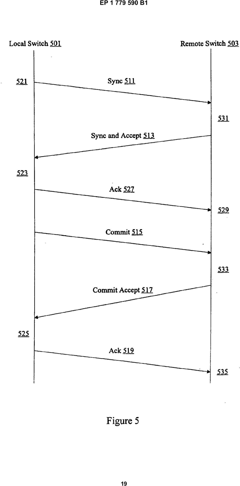
5 7 EP B1 8 gate physical ports. Figure 3 is a flow process diagram showing one technique for aggregating physical ports into a logical port. And 1, it is determined if auto create functionality is enabled. According to various embodiments, auto create functionality allows automatic configuration and detection of compatible physical ports as well as aggregation into one or more logical ports. Auto creation does not require user intervention. In other examples, administrators can manually arrange ports for aggregation. [0028] If auto create is not enabled, it is determined at if the port is part of a port channel. This determination can be made by using information provided by an administrator. If the port is not part of a port channel, no aggregation is necessary. However, if the port is part of a port channel, the bring up the procedure is run at 7 to either create a new port channel for the port or add the port to an existing port channel. [0029] If auto create is enabled at 1 a create procedure is run at 3. According to various embodiments, a create procedure runs compatibility checks at a local switch for potential candidate ports eligible to form a port channel. In some examples, the ports are locked during the compatibility checking so that compatibility parameter values cannot be changed until the checks are completed. Compatibility parameters include parameters such as line speed and trunking mode. The same compatibility parameters checked by an administrator during manual configuration can be checked during auto creation. A remote switch only needs to perform compatibility checks during particular circumstances such as circumstances triggered by a local switch. [00] After the create procedure is run, one or more ports may be grouped into port channels. If the port is part of a port channel at 9, a bring up procedure is run at 311. According to various embodiments, the bring up procedure is similar to that run at 7. If the port is not part of a port channel at 9, no additional processing is needed. [0031] Figure 4 is an exchange diagram showing one example of a bring up procedure used for a port creating a new port channel. A local switch 1 is coupled to a remote switch 3. The local switch 1 includes a physical port A1 coupled to physical port B1 included in remote switch 3. When two peer ports A1 and B1 are being aggregated into a port channel, the peer switches 1 and 3 typically already know the world wide names of the individual physical peer ports. However, the peer switches only know the world wide name of their own logical port or port channel. That is, both switches have the individual physical link configured, but the link is not yet part of a port channel. At 421, a local switch 1 sends a synchronize (sync) message 411 to the remote switch 3 to begin the process of creating a port channel including ports A1 and B1. [0032] In some examples, the sync message 411 includes a local port channel identifier and a remote port channel identifier. In one particular example, the local port channel identifier is set to the world wide name of the local port channel assigned by the local switch 1. The remote port channel identifier is left blank to indicate that the port A1 is being aggregated as part of a new port channel. The sync message 411 can also include other parameters such as channel status, channel model, or channel intent. [0033] At 431, remote switch 3 uses the information received from the local switch 1 to update a port channel database. In one example, the remote switch 3 can check if the port B1 is already assigned to a different port channel. If the port is not already assigned to a different port channel, the remote switch 3 can proceed and send a sync accept message 413 in response to the sync message 411. The sync accept message 413 includes a remote switch 3 assigned world wide name for the remote port channel identifier. The sync accept message indicates that a port channel can now be formed. At 423, local switch 1 uses the information to update its own port channel database. However, the port channel may not yet be operational until the hardware configuration is completed. The local switch 1 continues hardware configuration such as line card configuration to make the port A1 part of the port channel. An acknowledgment 427 is sent and received by remote switch 3 at 429. In some examples, the local switch 1 sends a commit signal 41 when hardware configuration is complete. [0034] The remote switch 3 receives the commit signal at 433 and begins its own hardware configuration. On completion of its hardware configuration, remote switch 3 sends out a commit accept signal 417 to indicate to local switch 1 that hardware configuration is completed. According to various embodiments, local switch 1 receives the commit accept signal 417 and notifies relevant applications that the port channel is now operational at 42 and that port A1 is the first operational port included. The local switch 1 sends an acknowledge message 419. When the remote switch 3 receives the acknowledge, it notifies relevant applications that the port channel is operational at 43 and that port B1 is the first operational port included. Figure 4 is an exchange diagram showing an example of a bring up procedure for the first port in a new port channel. [003] Figure is an exchange diagram depicting one example of a bring up procedure for a subsequent port added to the port channel. A local switch 01 is coupled to a remote switch 03. The local switch 01 includes a physical port A1 coupled to physical port B1 included in remote switch 03. The physical ports A1 and B1 are included in an existing port channel C1. Physical ports A2 and B2 are not yet included in the existing port channel C1. [0036] When two peer ports A2 and B2 are aggregated into a port channel C1, the peer switches 01 and 03 typically already know the world wide names of the individual physical peer ports A2 and B2 as well as the world wide name information of the port channel C1. Consequently, the port channel is already successfully estab-

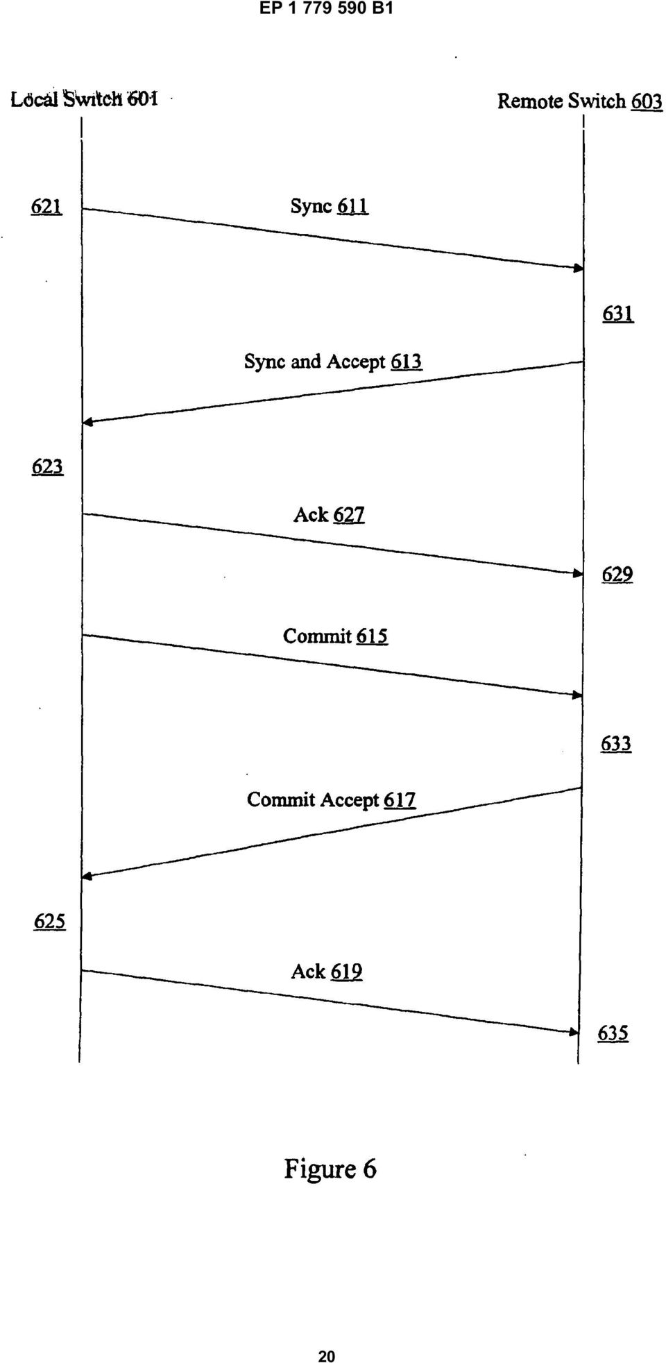
6 9 EP B1 lished. According to various embodiments, local switch 01 and remote switch 03 perform parameter checking to ensure that the new physical port A2 and B2 can be safely added to the existing port channel C1. At 21, a local switch can check configuration parameters to ensure that physical ports A1 and A2 at the local switch 01 are compatible. The compatibility checking can be performed anytime. In some examples, compatibility checking is checked before a local switch 01 sends a synchronize (sync) message 11 to the remote switch 03 to begin the process of aggregating ports A2 and B2 into the port channel. [0037] In some examples, the sync message 11 includes local port channel identifier and a remote port channel identifier. In one particular example, the local port channel identifier is set to the world wide name of the local port channel assigned by the local switch 01. The remote port channel identifier is filled with the existing port channel identifier to indicate that the port A2 is being aggregated into existing port channel C2. The sync message 11 can also include other parameters such as channel status, channel model, or channel intent. [0038] At 31, remote switch 03 uses the information received from the local switch 01 to verify port B2 is compatible with other port in port channel C2. In one example, configuration parameters associated with B2 are checked against configuration parameters associated with B1. The remote switch 03 can also check if the port B2 is already assigned to a different port channel. If the port B2 is compatible with port B1, the remote switch 03 can proceed and send a sync accept message 13 in response to the sync message 11 to indicate that the port B2 can be aggregated into the port channel. The sync accept message indicates that a port channel can now be modified. At 23, local switch 01 uses the information to update its own port channel database. However, the port channel may not yet be fully operational until the hardware configuration is completed. The local switch 01 continues hardware configuration such as line card configuration to make the port A2 part of the port channel C1. An acknowledgment 27 is sent and received by remote switch 03 at 29. In some examples, the local switch 01 sends a commit signal 1 when hardware configuration is complete. [0039] The remote switch 03 receives the commit signal at 33 and begins its own hardware configuration. On completion of its hardware configuration, remote switch 03 sends out a commit accept signal 17 to indicate to local switch 01 that hardware configuration is completed. According to various embodiments, local switch 01 receives the commit accept signal 17 and notifies relevant applications that the port channel is now fully operational at 2 and that port A2 has been aggregated into port channel C1. The local switch 01 can also send cut an acknowledge message 19. When the remote switch 03 receives the acknowledge, it notifies relevant applications that the port channel is operational at 3 and that port B2 has been aggregated into port channel C1. In one embodiments, the techniques of the present invention contemplate using a two phase SYNC and COMMIT mechanism similar to the mechanism used in EPP. [00] Figures 4 and show examples of ports being aggregated into a port channel. At a particular switch, ports can be selected for aggregation into a port channel in a variety of manners. Figure 6 is an exchange diagram showing automatic selection of ports at a switch for aggregation into a port channel. A local switch 601 is coupled to a remote switch 603. In one example, the local switch 601 includes physical ports A1, A2, A3, and A4 while remote switch 603 includes physical ports B1, B2, B3, and B4. No port channels have been formed. [0041] When a port channel is being automatically generated, the peer switches 601 and 603 typically already know the world wide names of the individual physical peer ports A1, A2, A3, A4, B1, B2, B3, and B4. The local switch 601 can perform configuration and parameter checking to determine which one of the physical ports A1, A2, A3, and A4 are compatible. However, the local switch 601 does not know whether physical ports B1, B2, B3, and B4 are compatible at the remote switch 603. According to various embodiments, local switch 601 performs compatibility checking to determine port channel arrangements and sends information to remote switch 603 to trigger compatibility checking remotely. For example, the local switch 601 may determine that ports A1, A2, and A4 are compatible and can form a port channel at 621. The local switch 621 then sends a synchronize (sync) message 611 to the remote switch 603 to begin the process of automatically generating a port channel C1. [0042] In some examples, the sync message 611 includes remote port identifiers A1, A2, and A4 indicating that the local ports A1, A2, and A4 are compatible and is transmitted to the remote switch 603 using ports A1 and B2. The sync message 611 can also include port channel identifiers for the compatible port channels that are already present on local switch 601. The sync message 611 can also include other parameters such as channel status, channel model, or channel intent. [0043] At 631, remote switch 603 uses the information received from the local switch 601 to verify that the peer ports of A1, A2, and A4 are compatible. That is, ports B1, B2, and B4 are checked for compatibility. In one example, only ports B1 and B2 may be compatible, and consequently only ports A1, A2, B1, and B2 can be included in the port channel. In another example, ports B1, B2, and B4 are compatible, so ports A1, A2, A4, B1, B2, and B4 can be aggregated into port channel C1. According to various embodiments, if the port B2 is compatible with port B1, the remote switch 603 can proceed and send a sync accept message 613 in response to the sync message 611 to indicate that the port B2 can be aggregated into the port channel. It should be noted that remote switch 603 can send a list indicating that ports B2 and B4 are compatible with B1. However, the remote switch 6
 message 11 to the remote switch 03 to begin the process of aggregating ports A2 and B2 into the")
7 11 EP B sends only one compatible port B2 back for several reasons, and in the process of selection compatible port channels get priority over compatible individual ports. [0044] One reason is that aggregation mechanisms and techniques can be implemented more elegantly by handling ports on an individual basis. Any individual port will either start a new port channel, be added to an existing port channel, or operate stand alone. There is no need to keep track of groups of ports to be aggregated. Another reason is that fewer ports need to be locked if only a single port is being aggregated at any one time. The sync accept message indicates that a port channel can now be modified. At 623, local switch 601 receives the information and recognizes that A1 and A2 can now be aggregated into port channel C1. However, the port channel may not yet be fully operational until the hardware configuration is completed. An acknowledgment 627 is sent and received by remote switch 603 at 629. In some examples, the local switch 601 sends a commit signal 61 when hardware configuration is complete. [004] The remote switch 603 receives the commit signal at 633 to create port channel C1 including ports B1 and B2. Hardware configuration can now be performed. On completion of its hardware configuration, remote switch 603 sends out a commit accept signal 617 to indicate to local switch 601 that hardware configuration is completed. According to various embodiments, local switch 601 receives the commit accept signal 617 and notifies relevant applications that the port channel is now fully operational at 62 and that ports A1 and A2 have been aggregated into port channel C1. The local switch 601 can also send out an acknowledge message 619. When the remote switch 603 receives the acknowledge, it notifies relevant applications that the port channel is fully operational at 63 and that ports B1 and B2 have been aggregated into port channel C1. [0046] The aggregation techniques allow efficient and automatic creation and bring up of port channels. Although the techniques do not have to be implemented in a synchronous manner, in many examples it is beneficial to bring up ports in order. [0047] Figure 7 is a diagrammatic representation showing synchronous aggregation of ports into a port channel. A local switch 701 is coupled to a remote switch 703 through links 721, 723, 72, and 727. According to various embodiments, the links are being aggregated into port channel 711 at the local switch 701 and port channel 713 at the remote switch 703 in a synchronous manner. That is the peer ports corresponding to each link are brought up in the same order at both the local switch 701 and the remote switch 703. [0048] A database such as a port channel map table is used store the links included in a port channel. The links and/or port information is entered into the table based on the order in which they were brought up. The port channel map table is used to select the physical link through which a frame is transmitted. In conventional implementations, the order of the peer ports listed in the port channel map table can be different for both the local switch 701 and the remote switch 703. [0049] Based on this scheme, frames for a given flow are transmitted through the same physical port of the port channel. However, unless there is proper synchronization of the port channel map tables at the two ends of a port channel, it is possible that requests and responses for the same flow are carried over two different physical links. For example, requests may be carried over link 721 while responses are carried over 723. This is undesirable for port channels as it affects applications like write acceleration that assume the traffic for a given flow is carried over the same physical link in both directions. [000] According to various embodiments of the present invention, links are brought up in order. A first link is selected for bring up. No effort is made to bring up other links is attempted until the exchange associated with the first link is completed. Consequently, port channel map tables at the local switch 701 and at the remote switch 703 are consistent. Port channel map table entries are synchronized at both ends so that all frames for a given flow are carried over the same physical link in both directions after the exchanges are completed. [001] As described above, techniques for aggregating ports may be performed in a variety of network devices or switches. According to various embodiments, a switch includes a processor, network interfaces, and memory. A variety of ports, Media Access Control (MAC) blocks, and buffers can also be provided as will be appreciated by one of skill in the art. [002] Figure 8 is a diagrammatic representation of one example of a fibre channel switch that can be used to implement techniques of the present invention. Although one particular configuration will be described, it should be noted that a wide variety of switch and router configurations are available. The fibre channel switch 801 may include one or more supervisors 811. According to various embodiments, the supervisor 811 has its own processor, memory, and storage resources. [003] Line cards 803, 80, and 807 can communicate with an active supervisor 811 through interface circuitry 883, 88, and 887 and the backplane 81. According to various embodiments, each line card includes a plurality of ports that can act as either input ports or output ports for communication with external fibre channel network entities 81 and 83. The backplane 81 can provide a communications channel for all traffic between line cards and supervisors. Individual line cards 803 and 807 can also be coupled to external fibre channel network entities 81 and 83 through fibre channel ports 843 and 847. [004] External fibre channel network entities 81 and 83 can be nodes such as other fibre channel switches, disks, RAIDS, tape libraries, or servers. It should be noted that the switch can support any number of line cards and super visors. In the embodiment shown, only a single supervisor is connected to the backplane 81 and the single supervisor communicates with many different line cards. The active supervisor 811 may be configured or 7

8 13 EP B1 14 designed to run a plurality of applications such as routing, domain manager, system manager, and utility applications. [00] According to one embodiment, the routing application is configured to provide credits to a sender upon recognizing that a frame has been forwarded to a next hop. A utility application can be configured to track the number of buffers and the number of credits used. A domain manager application can be used to assign domains in the fibre channel storage area network. Various supervisor applications may also be configured to provide functionality such as flow control, credit management, and quality of service (QoS) functionality for various fibre channel protocol layers. [006] In addition, although an exemplary switch is described, the above-described embodiments may be implemented in a variety of network devices (e.g., servers) as well as in a variety of mediums. For instance, instructions and data for implementing the above-described invention may be stored on a disk drive, a hard drive, a floppy disk, a server computer, or a remotely networked computer. Accordingly, the present embodiments are to be considered as illustrative and not restrictive, and the invention is not to be limited to the details given herein, but may be modified within the scope and equivalents of the appended claims. [007] While the invention has been particularly shown and described with reference to specific embodiments thereof, it will be understood by those skilled in the art that changes in the form and details of the disclosed embodiments may be made without departing from the spirit or scope of the invention. For example, embodiments of the present invention may be employed with a variety of network protocols and architectures. It is therefore intended that the invention be interpreted to include all variations and equivalents that fall within the scope of the present invention. Claims 1. A method for aggregating ports in a fibre channel fabric, the method comprising: determining that a plurality of local ports (243, 24) at a local fibre channel switch (1) are compatible by running compatibility checks at the local fibre channel switch to determine that the plurality of local ports are eligible to form a port channel (23); sending identifiers for the plurality of local ports (243, 24) to a remote fibre channel switch (3); wherein responsive to receiving the identifiers for the plurality of local ports the remote fibre channel switch (3) determines if a plurality of remote ports (263, 26) are compatible to form a port channel (23), the plurality of remote ports corresponding to the plurality of local ports; and characterized by: receiving an indication at the local fibre channel switch (1) that one or more of the remote physical ports have been determined to be compatible to form a port channel; and creating a port channel (23) including one or more of the local ports (243, 24) corresponding to the compatible remote ports (263, 26). 2. The method of claim 1, wherein the port channel (23) is a logical port. 3. The method of any of claims 1-2, wherein the remote fibre channel switch (3) determines if the plurality of remote ports (263, 26) are compatible with each other. 4. The method of any of claims 1-3, wherein creating a local port channel comprises providing a unique local port channel identifier.. The method of claim 4, wherein the unique local port channel identifier is a local port channel world wide name (WWN). 6. The method of claim, wherein the remote fibre channel switch (3) creates a remote port channel corresponding to the local port channel. 7. The method of claim 6, wherein the remote port channel is provided a unique remote port channel identifier. 8. The method of claim 7, wherein the unique remote port channel identifier is a remote port channel WWN. 9. The method of claim any of claims 1-8, wherein determining that the plurality of ports are compatible comprises determining if the plurality of ports have the same operation parameters.. The method of claim 9, therein operation parameters include port speed. 11. The method of claim 1, therein the plurality of local ports (243, 24) are aggregated into the port channel (23) in a synchronous manner. 12. A fibre channel switch (1), comprising: memory; a plurality of local ports (243, 24) coupled to a remote fibre channel switch (3) through a plu- 8

9 1 EP B1 16 rality of remote ports (263, 26); a processor configured to determine that a subset of the plurality of local ports at a local fibre channel switch (1) are compatible by running compatibility checks at the local fibre channel switch to determine that the plurality of local ports are eligible to form a port channel (23) and send identifiers for the subset of the plurality of local ports to a remote fibre channel switch (3), wherein responsive to receiving the identifiers for the plurality of local ports the remote fibre channel switch (3) determines if a subset of the plurality of remote ports are compatible to form a port channel, the subset of the plurality of remote ports corresponding to the subset of the plurality of local ports; and characterized in that: the processor is further configured to receive an indication that one or more of the remote physical ports have been determined to be compatible to form a port channel and create a port channel (23) including two or more of the local ports corresponding to the compatible remote ports. 13. The fibre channel switch of of claim 12, wherein the port channel (23) is a logical port. 14. The fibre channel switch of any of claims 12-13, wherein the remote fibre channel switch (3) determines if the subset of the plurality of remote ports are compatible with each other. 1. The fibre channel switch of any of claims 12-14, wherein creating a local port channel comprises providing a unique local port channel identifier. 16. The fibre channel switch of claim 1, wherein the unique local port channel identifier is a local port channel world wide name (WWN). 17. The fibre channel switch of claim 16, wherein the remote fibre channel switch creates a remote port channel corresponding to the local port channel. 18. The fibre channel switch of claim 17, wherein the remote port channel is provided a unique remote port channel identifier. 19. The fibre channel switch of claim 18, wherein the unique remote port channel identifier is a remote port channel WWN.. The fibre channel switch of any of claims 12-19, wherein determining that the plurality of ports are compatible comprises determining if the plurality of ports have the same configuration parameters The fibre channel switch of claim, wherein operation parameters include port speed. 22. The fibre channel switch of claim 12, wherein the plurality of local ports are aggregated into the port channel in a synchronous manner. 23. A fibre channel network, comprising: a local fibre channel switch (1) including a plurality of local ports (243, 24); and a remote fibre channel switch (3) including a plurality of remote port (263, 26); wherein the local fibre channel switch (1) determines a subset of the plurality of local ports compatible to form a port channel by running a compatibility check and sends identifiers for the compatible subset of the plurality of local ports to the remote fibre channel switch (3), wherein the remote fibre channel switch determines if a subset of the plurality of remote ports are compatible to form a port channel, the subset of the plurality of remote ports corresponding to the compatible subset of the plurality of local ports; and characterized in that the local fibre channel switch (1) is further configured to receive an indication that two or more of the remote physical ports are compatible to form a port channel and create a port channel (23) including two or more of the local ports corresponding to the compatible remote ports. 24. The fibre channel network of claim 23, wherein the port channel (23) is a logical port. 2. The fibre channel network of any of claims 23-24, wherein the remote fibre channel switch (3) determines if the subset of the plurality of remote ports are compatible with each other. 26. The fibre channel network of any of claims 23-2, wherein creating a local port channel comprises providing a unique local port channel identifier. 27. The fibre channel network of claim 26, wherein the unique local port channel identifier is a local port channel world wide name (WWN). 28. An apparatus for aggregating physical ports in a fibre channel fabric, the apparatus comprising: means for determining that a plurality of local ports at a local fibre channel switch (1) are compatible by running compatibility checks at the local fibre channel switch to determine that the plurality of local ports are eligible to form a port channel (23); means for sending identifiers for the plurality of 9

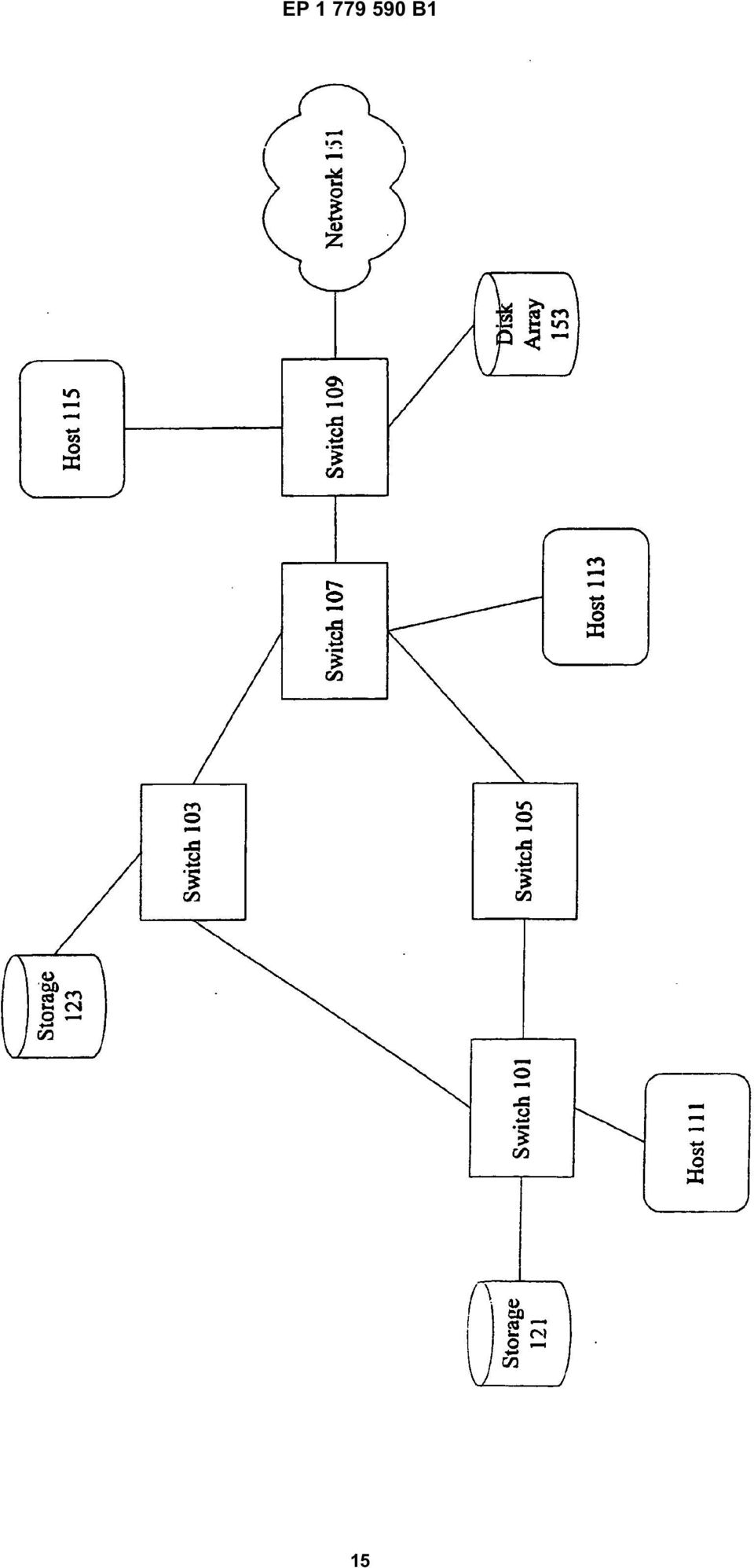
10 17 EP B1 18 local ports to a remote fibre channel switch (3), wherein responsive to receiving the identifiers for the plurality of local ports the remote fibre channel switch determines if a plurality of remote ports are compatible to form a port channel, the plurality of remote port corresponding to the plurality of local ports; means for receiving an indication that two or more of the remote physical ports are compatible to form a port channel; means for creating a port channel (23) including two or more of the local ports corresponding to the compatible remote ports. Patentansprüche 1. Verfahren zum Aggregieren von Ports in einer Fibre Channel Fabric, wobei das Verfahren umfasst: Ermitteln, dass eine Vielzahl von lokalen Ports (243, 24) an einem lokalen Fibre Channel Switch (1) kompatibel sind, durch Laufenlassen von Kompatibilitätsprüfungen an dem lokalen Fibre Channel Switch, um zu ermitteln, dass die Vielzahl von lokalen Ports zur Bildung eines Port Channel (23) geeignet sind; Senden von Identifizierern für die Vielzahl von lokalen Ports (243, 24) an einen fernen Fibre Channel Switch (3); wobei im Ansprechen auf das Empfangen der Identifizierer für die Vielzahl von lokalen Ports der ferne Fibre Channel Switch (3) ermittelt, ob eine Vielzahl von fernen Ports (263, 26) kompatibel sind, um einen Port Channel (23) zu bilden, wobei die Vielzahl von fernen Ports der Vielzahl von lokalen Ports entspricht; und gekennzeichnet durch: Empfangen einer Anzeige an dem lokalen Fibre Channel Switch (1), dass ermittelt worden ist, dass einer oder mehrere der fernen physikalischen Ports kompatibel ist / sind, um einen Port Channel zu bilden; und Erzeugen eines Port Channel (23), der einen oder mehrere der lokalen Ports (243, 24) enthält, die den kompatiblen fernen Ports (263, 26) entsprechen. 2. Verfahren nach Anspruch 1, wobei der Port Channel (23) ein logischer Port ist. 3. Verfahren nach einem der Ansprüche 1 und 2, wobei der ferne Fibre Channel Switch (3) ermittelt, ob die Vielzahl von fernen Ports (263, 26) miteinander kompatibel sind. 4. Verfahren nach einem der Ansprüche 1 bis 3, wobei das Erzeugen eines lokalen Port Channel das Bereitstellen eines eindeutigen lokalen Port Channel Identifizierers umfasst.. Verfahren nach Anspruch 4, wobei der eindeutige lokale Port Channel Identifizierer ein lokaler Port Channel World Wide Name (WWN) ist. 6. Verfahren nach Anspruch, wobei der ferne Fibre Channel Switch (3) einen fernen Port Channel erzeugt, der dem lokalen Port Channel entspricht. 7. Verfahren nach Anspruch 6, wobei der ferne Port Channel mit einem eindeutigen fernen Port Channel Identifizierer versehen ist. 8. Verfahren nach Anspruch 7, wobei der eindeutige ferne Port Channel Identifizierer ein ferner Port Channel WWN ist. 9. Verfahren nach einem der Ansprüche 1 bis 8, wobei das Ermitteln, dass die Vielzahl von Ports kompatibel sind, das Ermitteln umfasst, ob die Vielzahl von Ports dieselben Betriebsparameter haben.. Verfahren nach Anspruch 9, wobei die Betriebsparameter Portgeschwindigkeit enthalten. 11. Verfahren nach Anspruch 1, wobei die Vielzahl von lokalen Ports (243, 24) synchron in den Port Channel (23) aggregiert werden. 12. Fibre Channel Switch (1) mit: einem Speicher; einer Vielzahl von lokalen Ports (243, 24), die durch eine Vielzahl von fernen Ports (263, 26) mit einem fernen Fibre Channel Switch (3) verbunden sind; einem Prozessor, der so konfiguriert ist, dass er ermittelt, dass eine Untermenge der Vielzahl von lokalen Ports an einem lokalen Fibre Channel Switch (1) kompatibel sind, durch Laufenlassen von Kompatibilitätsprüfungen an dem lokalen Fibre Channel Switch, um zu ermitteln, dass die Vielzahl von lokalen Ports zur Bildung eines Port Channel (23) geeignet sind, und dass er Identifizierer für die Untermenge der Vielzahl von lokalen Ports an einen fernen Fibre Channel Switch (3) sendet, wobei im Ansprechen auf das Empfangen der Identifizierer für die Vielzahl von lokalen Ports der ferne Fibre Channel Switch (3) ermittelt, ob eine Untermenge der Vielzahl von fernen Ports (263, 26) kompatibel ist, um einen Port Channel (23) zu bilden, wobei die Untermenge der Vielzahl von fernen Ports der Untermenge der Vielzahl von lokalen Ports entspricht; und dadurch gekenn-

11 19 EP B1 zeichnet, dass: der Prozessor des Weiteren so konfiguriert ist, dass er eine Anzeige empfängt, dass ermittelt worden ist, dass einer oder mehrere der fernen physikalischen Ports kompatibel ist / sind, um einen Port Channel zu bilden, und dass er einen Port Channel (23) erzeugt, der zwei oder mehrere der lokalen Ports (243, 24) enthält, die den kompatiblen fernen Ports entsprechen. 13. Fibre Channel Switch nach Anspruch 12, wobei der Port Channel (23) ein logischer Port ist. 14. Fibre Channel Switch nach einem der Ansprüche 12 und 13, wobei der ferne Fibre Channel Switch (3) ermittelt, ob die Untermenge der Vielzahl von fernen Ports miteinander kompatibel ist. 1. Fibre Channel Switch nach einem der Ansprüche 12 bis 14, wobei das Erzeugen eines lokalen Port Channel das Bereitstellen eines eindeutigen Port Channel Identifizierers umfasst. 16. Fibre Channel Switch nach Anspruch 1, wobei der eindeutige lokale Port Channel Identifizierer ein lokaler Port Channel World Wide Name (WWN) ist. 17. Fibre Channel Switch nach Anspruch 16, wobei der ferne Fibre Channel Switch einen fernen Port Channel erzeugt, der dem lokalen Port Channel entspricht. 18. Fibre Channel Switch nach Anspruch 17, wobei der ferne Port Channel mit einem eindeutigen fernen Port Channel Identifizierer versehen ist. 19. Fibre Channel Switch nach Anspruch 18, wobei der eindeutige ferne Port Channel Identifizierer ein ferner Port Channel WWN ist.. Fibre Channel Switch nach einem der Ansprüche 12 bis 19, wobei das Ermitteln, dass die Vielzahl von Ports kompatibel sind, das Ermitteln umfasst, ob die Vielzahl von Ports dieselben Konfigurationsparameter haben. 21. Fibre Channel Switch nach Anspruch, wobei die Betriebsparameter Portgeschwindigkeit enthalten. 22. Fibre Channel Switch nach Anspruch 12, wobei die Vielzahl von lokalen Ports synchron in den Port Channel aggregiert werden. 23. Fibre Channel Netzwerk mit: einem lokalen Fibre Channel Switch (1) mit einer Vielzahl von lokalen Ports (243, 24); und einem fernen Fibre Channel Switch (3) mit einer Vielzahl von fernen Ports (263, 26); wobei der lokale Fibre Channel Switch (1) ermittelt, dass eine Untermenge der Vielzahl von lokalen Ports kompatibel ist, um einen Port Channel zu bilden, durch Laufenlassen einer Kompatibilitätsprüfung, und Identifizierer für die kompatible Untermenge der Vielzahl von lokalen Ports an den fernen Fibre Channel Switch (3) sendet, wobei der ferne Fibre Channel Switch ermittelt, ob eine Untermenge der Vielzahl von fernen Ports kompatibel ist, um einen Port Channel zu bilden, wobei die Untermenge der Vielzahl von fernen Ports der kompatiblen Untermenge der Vielzahl von lokalen Ports entspricht; und dadurch gekennzeichnet, dass: der lokale Fibre Channel Switch (1) des Weiteren so konfiguriert ist, dass er eine Anzeige empfängt, dass zwei oder mehrere der fernen physikalischen Ports kompatibel sind, um einen Port Channel zu bilden, und dass er einen Port Channel (23) erzeugt, der zwei oder mehrere der lokalen Ports enthält, die den kompatiblen fernen Ports entsprechen. 24. Fibre Channel Netzwerk nach Anspruch 23, wobei der Port Channel (23) ein logischer Port ist. 2. Fibre Channel Netzwerk nach einem der Ansprüche 23 und 24, wobei der ferne Fibre Channel Switch (3) ermittelt, ob die Untermenge der Vielzahl von fernen Ports miteinander kompatibel ist. 26. Fibre Channel Netzwerk nach einem der Ansprüche 23 bis 2, wobei das Erzeugen eines lokalen Port Channel das Bereitstellen eines eindeutigen lokalen Port Channel Identifizierers umfasst. 27. Fibre Channel Netzwerk nach Anspruch 26, wobei der eindeutige lokale Port Channel Identifizierer ein lokaler Port Channel World Wide Name (WWN) ist. 28. Vorrichtung zum Aggregieren von physikalischen Ports in einer Fibre Channel Fabric, wobei die Vorrichtung aufweist: eine Einrichtung zum Ermitteln, dass eine Vielzahl von lokalen Ports an einem lokalen Fibre Channel Switch (1) kompatibel sind, durch Laufenlassen von Kompatibilitätsprüfungen an dem lokalen Fibre Channel Switch, um zu ermitteln, dass die Vielzahl von lokalen Ports zur Bildung eines Port Channel (23) geeignet sind; eine Einrichtung zum Senden von Identifizierern für die Vielzahl von lokalen Ports an einen fernen Fibre Channel Switch (3), wobei im Ansprechen auf das Empfangen der Identifizierer für 11

12 21 EP B1 22 die Vielzahl von lokalen Ports der ferne Fibre Channel Switch ermittelt, ob eine Vielzahl von fernen Ports kompatibel sind, um einen Port Channel zu bilden, wobei die Vielzahl von fernen Ports der Vielzahl von lokalen Ports entspricht; eine Einrichtung zum Empfangen einer Anzeige, dass zwei oder mehrere der fernen physikalischen Ports kompatibel sind, um einen Port Channel zu bilden; und eine Einrichtung zum Erzeugen eines Port Channel (23), der zwei oder mehrere der lokalen Ports enthält, die den kompatiblen fernen Ports entsprechen. Revendications 1. Procédé permettant de grouper des points d accès dans une matrice de canal de fibre optique, le procédé comprenant les étapes consistant à : déterminer qu une pluralité de points d accès locaux (243, 24) au niveau d un commutateur de canal de fibre optique (1) sont compatibles en effectuant des vérifications de compatibilité au niveau du commutateur du canal de fibre optique local pour déterminer que la pluralité de points d accès locaux sont éligibles pour former un canal de point d accès (23) ; envoyer des identifiants pour la pluralité de points d accès locaux (243, 24) à un commutateur de canal de fibre optique distant (3) ; dans lequel en réponse à la réception d identifiants pour la pluralité de points d accès locaux, le commutateur de canal de fibre optique distant (3) détermine si une pluralité de points d accès distants (263, 26) sont compatibles pour former un canal de point d accès (23), la pluralité de points d accès distants correspondant à la pluralité de points d accès locaux ; et caractérisé par les étapes consistant à : recevoir une indication au niveau du commutateur de canal de fibre optique local (1) selon laquelle un ou plusieurs des points d accès physiques distants a été déterminé comme étant compatible pour former un canal de point d accès ; et créer un canal de point d accès (23) comprenant un ou plusieurs des points d accès locaux (243, 24) correspondant aux points d accès distants compatibles (263, 26). 2. Procédé selon la revendication 1, dans lequel le canal de point d accès (23) est un point d accès logique. 3. Procédé selon l une quelconque des revendications à 2, dans lequel le commutateur de canal de fibre optique distant (3) détermine si la pluralité de points d accès distants (263, 26) sont compatibles les uns avec les autres. 4. Procédé selon l une quelconque des revendications 1 à 3, dans lequel la création d un canal de point d accès local comprend l étape consistant à fournir un identifiant de canal de point d accès local unique.. Procédé selon la revendication 4, dans lequel l identifiant de canal de point d accès local unique est une convention de nom commun (WWN pour World Wide Name) de canal de point d accès local. 6. Procédé selon la revendication, dans lequel le commutateur de canal de fibre optique distant (3) crée un canal de point d accès distant correspondant au canal de point d accès local. 7. Procédé selon la revendication 6, dans lequel le canal de point d accès distant est doté d un identifiant de canal de point d accès distant unique. 8. Procédé selon la revendication 7, dans lequel l identifiant de canal de point d accès distant unique est une convention de nom commun (WWN) de canal de point d accès distant. 9. Procédé selon l une quelconque des revendications 1 à 8, dans lequel l étape consistant à déterminer que la pluralité de points d accès sont compatibles comprend la sous-étape consistant à déterminer si la pluralité de points d accès ont les mêmes paramètres de fonctionnement.. Procédé selon la revendication 9, dans lequel les paramètres de fonctionnement comprennent la vitesse de point d accès. 11. Procédé selon la revendication 1, dans lequel la pluralité de points d accès locaux (243, 24) sont groupés dans le canal de point d accès (23) de façon synchrone. 12. Commutateur de canal de fibre optique (1), comprenant : une mémoire ; une pluralité de points d accès locaux (243, 24) couplés à un commutateur de canal de fibre optique distant (3) via une pluralité de points d accès distants (263, 26) ; un processeur configuré pour déterminer qu un sous-ensemble de la pluralité de points d accès locaux au niveau d un commutateur de canal de fibre optique local (1) est compatible en effectuant des vérifications de compatibilité au ni- 12

13 23 EP B1 24 veau du commutateur du canal de fibre optique local pour déterminer que la pluralité de points d accès locaux sont éligibles pour former un canal de point d accès (23) et envoyer des identifiants pour le sous-ensemble de la pluralité de points d accès locaux à un commutateur de canal de fibre optique distant (3), dans lequel en réponse à la réception des identifiants pour la pluralité de points d accès locaux, le commutateur de canal de fibre optique (3) détermine si un sous-ensemble de la pluralité de points d accès distants est compatible pour former un canal de point d accès, le sous-ensemble de la pluralité de points d accès distants correspondant au sous-ensemble de la pluralité de points d accès locaux ; et caractérisé en ce que : le processeur est en outre configuré pour recevoir une indication selon laquelle un ou plusieurs des points d accès physiques distants a été déterminé comme étant compatible pour former un canal de point d accès et créer un canal de point d accès (23) comprenant deux ou plus des points d accès locaux correspondant aux points d accès distants compatibles. 13. Commutateur de canal de fibre optique selon la revendication 12, dans lequel le canal de point d accès (23) est un point d accès logique. 14. Commutateur de canal de fibre optique selon l une quelconque des revendications 12 à 13, dans lequel le commutateur de canal de fibre optique distant (3) détermine si le sous-ensemble de la pluralité de points d accès distants est compatible l un avec l autre. 1. Commutateur de canal de fibre optique selon l une quelconque des revendications 12 à 14, dans lequel la création d un canal de point d accès local comprend l étape consistant à fournir un identifiant de canal de point d accès local unique. 16. Commutateur de fibre optique selon la revendication 1, dans lequel l identifiant de canal de point d accès local unique est une convention de nom commun (WWN) de canal de point d accès local. 17. Commutateur de canal de fibre optique selon la revendication 16, dans lequel le commutateur de canal de fibre optique distant crée un canal de point d accès distant correspondant au canal de point d accès local. 18. Commutateur de canal de fibre optique selon la revendication 17, dans lequel le canal de point d accès distant est doté d un identifiant de canal de point d accès distant unique. 19. Commutateur de canal de fibre optique selon la revendication 18, dans lequel l identifiant de canal de point d accès distant unique est une convention de nom commun (WWN) de canal de point d accès distant.. Commutateur de canal de fibre optique selon l une quelconque des revendications 12 à 19, dans lequel l étape consistant à déterminer que la pluralité de points d accès sont compatibles comprend la sousétape consistant à déterminer si la pluralité de points d accès ont les mêmes paramètres de configuration. 21. Commutateur de canal de fibre optique selon la revendication, dans lequel les paramètres de fonctionnement comprennent la vitesse de point d accès. 22. Commutateur de canal de fibre optique selon la revendication 12, dans lequel la pluralité de points d accès locaux sont groupés dans le canal de point d accès de façon synchrone. 23. Réseau de canaux de fibre optique, comprenant : un commutateur de canal de fibre optique local (1) comprenant une pluralité de points d accès locaux (243, 24) ; et un commutateur de canal de fibre optique distant (3) comprenant une pluralité de points d accès distants (263, 26) ; dans lequel le commutateur de canal de fibre optique (1) détermine un sous-ensemble de la pluralité de points d accès locaux compatibles pour former un canal de point d accès en effectuant une vérification de compatibilité et envoie des identifiants pour le sous-ensemble compatible de la pluralité de points d accès locaux au commutateur de canal de fibre optique distant (3), dans lequel le commutateur de canal de fibre optique distant détermine si un sous-ensemble de la pluralité de points d accès distants est compatible pour former un canal de point d accès, le sous-ensemble de la pluralité de points d accès distants correspondant au sousensemble compatible de la pluralité de points d accès locaux ; et caractérisé en ce que le commutateur de canal de fibre optique local (1) est en outre configuré pour recevoir une indication selon laquelle deux ou plus des points d accès physiques distants sont compatibles pour former un canal de point d accès et créer un canal de point d accès (23) comprenant deux ou plus des points d accès locaux correspondant aux points d accès distants compatibles. 13

14 2 EP B Réseau de canaux de fibre optique selon la revendication 23, dans lequel le canal de point d accès (23) est un point d accès logique. 2. Réseau de canaux de fibre optique selon l une quelconque des revendications 23 à 24, dans lequel le commutateur de canal de fibre optique distant (3) détermine si le sous-ensemble de la pluralité de points d accès distants est compatible l un avec l autre. 26. Réseau de canaux de fibre optique selon l une quelconque des revendications 23 à 2, dans lequel la création d un canal de point d accès local comprend l étape consistant à fournir un identifiant de canal de point d accès local unique Réseau de canaux de fibre optique selon la revendication 26, dans lequel l identifiant de canal de point d accès local unique est une convention de nom commun (WWN) de canal de point d accès local. 28. Appareil permettant de grouper des points d accès physiques dans une matrice de canal de fibre optique, l appareil comprenant : 2 un moyen pour déterminer qu une pluralité de points d accès locaux à un commutateur de canal de fibre optique local (1) sont compatibles en effectuant des vérifications de compatibilité au niveau du commutateur de canal de fibre optique local pour déterminer que la pluralité de points d accès locaux sont éligibles pour former un canal de point d accès (23) ; un moyen pour envoyer des identifiants pour la pluralité de points d accès locaux à un commutateur de canal de fibre optique distant (3), dans lequel en réponse à la réception des identifiants pour la pluralité de points d accès locaux, le commutateur de canal de fibre optique distant détermine si une pluralité de points d accès distants sont compatibles pour former un canal de point d accès, la pluralité de points d accès distants correspondant à la pluralité de points d accès locaux ; un moyen pour recevoir une indication que deux ou plus des points d accès physiques distants sont compatibles pour former un canal de point d accès ; un moyen pour créer un canal de point d accès (23) comprenant deux ou plus des points d accès locaux correspondants aux points d accès distants compatibles
 détermine si le sous-ensemble de la pluralité de")
15 EP B1 1
16 EP B1 16

17 EP B1 17

18 EP B1 18

19 EP B1 19
20 EP B1
TEPZZ 6_Z76 A_T EP 2 610 763 A1 (19) (11) EP 2 610 763 A1 (12) EUROPEAN PATENT APPLICATION. (51) Int Cl.:
 (11) EP 2 610 763 A1 (12) EUROPEAN PATENT APPLICATION. (51) Int Cl.:") (19) TEPZZ 6_Z76 A_T (11) EP 2 6 763 A1 (12) EUROPEAN PATENT APPLICATION (43) Date of publication: 03.07.2013 Bulletin 2013/27 (51) Int Cl.: G06F 17/30 (2006.01) (21) Application number: 12192220.7 (22)
(19) TEPZZ 6_Z76 A_T (11) EP 2 6 763 A1 (12) EUROPEAN PATENT APPLICATION (43) Date of publication: 03.07.2013 Bulletin 2013/27 (51) Int Cl.: G06F 17/30 (2006.01) (21) Application number: 12192220.7 (22)
(51) Int Cl.: G10L 15/26 (2006.01)
 Int Cl.: G10L 15/26 (2006.01)") (19) TEPZZ Z 8B_T (11) EP 2 023 338 B1 (12) EUROPEAN PATENT SPECIFICATION (4) Date of publication and mention of the grant of the patent: 28.0.14 Bulletin 14/22 (1) Int Cl.: GL /26 (06.01) (21) Application
(19) TEPZZ Z 8B_T (11) EP 2 023 338 B1 (12) EUROPEAN PATENT SPECIFICATION (4) Date of publication and mention of the grant of the patent: 28.0.14 Bulletin 14/22 (1) Int Cl.: GL /26 (06.01) (21) Application
TEPZZ 87_546A T EP 2 871 546 A2 (19) (11) EP 2 871 546 A2 (12) EUROPEAN PATENT APPLICATION. (51) Int Cl.: G05B 19/05 (2006.01)
 (11) EP 2 871 546 A2 (12) EUROPEAN PATENT APPLICATION. (51) Int Cl.: G05B 19/05 (2006.01)") (19) TEPZZ 87_46A T (11) EP 2 871 46 A2 (12) EUROPEAN PATENT APPLICATION (43) Date of publication: 13.0.1 Bulletin 1/ (1) Int Cl.: G0B 19/0 (06.01) (21) Application number: 14188238.1 (22) Date of filing:
(19) TEPZZ 87_46A T (11) EP 2 871 46 A2 (12) EUROPEAN PATENT APPLICATION (43) Date of publication: 13.0.1 Bulletin 1/ (1) Int Cl.: G0B 19/0 (06.01) (21) Application number: 14188238.1 (22) Date of filing:
(51) Int Cl.: H04L 9/32 (2006.01) G09C 1/00 (2006.01) G06F 21/33 (2013.01) H04L 29/06 (2006.01)
 Int Cl.: H04L 9/32 (2006.01) G09C 1/00 (2006.01) G06F 21/33 (2013.01) H04L 29/06 (2006.01)") (19) TEPZZ Z48B_T (11) EP 2 2 048 B1 (12) EUROPEAN PATENT SPECIFICATION (4) Date of publication and mention of the grant of the patent: 13.0. Bulletin / (21) Application number: 1179238.6 (22) Date of
(19) TEPZZ Z48B_T (11) EP 2 2 048 B1 (12) EUROPEAN PATENT SPECIFICATION (4) Date of publication and mention of the grant of the patent: 13.0. Bulletin / (21) Application number: 1179238.6 (22) Date of
(51) Int Cl.: H04L 29/06 (2006.01) H04M 15/00 (2006.01)
 Int Cl.: H04L 29/06 (2006.01) H04M 15/00 (2006.01)") (19) TEPZZ 7Z 74 B_T (11) EP 2 702 742 B1 (12) EUROPEAN PATENT SPECIFICATION (4) Date of publication and mention of the grant of the patent:.04. Bulletin /16 (21) Application number: 1171674.6 (22) Date
(19) TEPZZ 7Z 74 B_T (11) EP 2 702 742 B1 (12) EUROPEAN PATENT SPECIFICATION (4) Date of publication and mention of the grant of the patent:.04. Bulletin /16 (21) Application number: 1171674.6 (22) Date
TEPZZ 9 Z5A_T EP 2 922 305 A1 (19) (11) EP 2 922 305 A1. (12) EUROPEAN PATENT APPLICATION published in accordance with Art.
 (11) EP 2 922 305 A1. (12) EUROPEAN PATENT APPLICATION published in accordance with Art.") (19) TEPZZ 9 ZA_T (11) EP 2 922 A1 (12) EUROPEAN PATENT APPLICATION published in accordance with Art. 13(4) EPC (43) Date of publication: 23.09.1 Bulletin 1/39 (21) Application number: 1386446.2 (22) Date
(19) TEPZZ 9 ZA_T (11) EP 2 922 A1 (12) EUROPEAN PATENT APPLICATION published in accordance with Art. 13(4) EPC (43) Date of publication: 23.09.1 Bulletin 1/39 (21) Application number: 1386446.2 (22) Date
EP 2 455 926 A1 (19) (11) EP 2 455 926 A1 (12) EUROPEAN PATENT APPLICATION. (43) Date of publication: 23.05.2012 Bulletin 2012/21
 (11) EP 2 455 926 A1 (12) EUROPEAN PATENT APPLICATION. (43) Date of publication: 23.05.2012 Bulletin 2012/21") (19) (12) EUROPEAN PATENT APPLICATION (11) EP 2 4 926 A1 (43) Date of publication: 23.0.2012 Bulletin 2012/21 (21) Application number: 11190024.7 (1) Int Cl.: G08B 2/14 (2006.01) G08B 2/00 (2006.01) G0B
(19) (12) EUROPEAN PATENT APPLICATION (11) EP 2 4 926 A1 (43) Date of publication: 23.0.2012 Bulletin 2012/21 (21) Application number: 11190024.7 (1) Int Cl.: G08B 2/14 (2006.01) G08B 2/00 (2006.01) G0B
(51) Int Cl.: G06F 9/455 (2006.01) G06F 9/50 (2006.01)
 Int Cl.: G06F 9/455 (2006.01) G06F 9/50 (2006.01)") (19) TEPZZ 6987 B_T (11) EP 2 698 711 B1 (12) EUROPEAN PATENT SPECIFICATION (4) Date of publication and mention of the grant of the patent: 0.08.1 Bulletin 1/32 (21) Application number: 118777.8 (22) Date
(19) TEPZZ 6987 B_T (11) EP 2 698 711 B1 (12) EUROPEAN PATENT SPECIFICATION (4) Date of publication and mention of the grant of the patent: 0.08.1 Bulletin 1/32 (21) Application number: 118777.8 (22) Date
TEPZZ 69 49A_T EP 2 693 349 A1 (19) (11) EP 2 693 349 A1 (12) EUROPEAN PATENT APPLICATION. (51) Int Cl.: G06F 17/30 (2006.01)
 (11) EP 2 693 349 A1 (12) EUROPEAN PATENT APPLICATION. (51) Int Cl.: G06F 17/30 (2006.01)") (19) TEPZZ 69 49A_T (11) EP 2 693 349 A1 (12) EUROPEAN PATENT APPLICATION (43) Date of publication: 0.02.2014 Bulletin 2014/06 (1) Int Cl.: G06F 17/30 (2006.01) (21) Application number: 13160696.4 (22)
(19) TEPZZ 69 49A_T (11) EP 2 693 349 A1 (12) EUROPEAN PATENT APPLICATION (43) Date of publication: 0.02.2014 Bulletin 2014/06 (1) Int Cl.: G06F 17/30 (2006.01) (21) Application number: 13160696.4 (22)
TEPZZ 68575_A_T EP 2 685 751 A1 (19) (11) EP 2 685 751 A1. (12) EUROPEAN PATENT APPLICATION published in accordance with Art.
 (11) EP 2 685 751 A1. (12) EUROPEAN PATENT APPLICATION published in accordance with Art.") (19) TEPZZ 687_A_T (11) EP 2 68 71 A1 (12) EUROPEAN PATENT APPLICATION published in accordance with Art. 3(4) EPC (43) Date of publication:.01.14 Bulletin 14/03 (21) Application number: 1278849.6 (22)
(19) TEPZZ 687_A_T (11) EP 2 68 71 A1 (12) EUROPEAN PATENT APPLICATION published in accordance with Art. 3(4) EPC (43) Date of publication:.01.14 Bulletin 14/03 (21) Application number: 1278849.6 (22)
*EP001173363B1* EP 1 173 363 B1 (19) (11) EP 1 173 363 B1 (12) EUROPEAN PATENT SPECIFICATION
 (11) EP 1 173 363 B1 (12) EUROPEAN PATENT SPECIFICATION") (19) Europäisches Patentamt European Patent Office Office européen des brevets *EP001173363B1* (11) EP 1 173 363 B1 (12) EUROPEAN PATENT SPECIFICATION (4) Date of publication and mention of the grant of
(19) Europäisches Patentamt European Patent Office Office européen des brevets *EP001173363B1* (11) EP 1 173 363 B1 (12) EUROPEAN PATENT SPECIFICATION (4) Date of publication and mention of the grant of
(51) Int Cl.: B29C 41/20 (2006.01) F21S 4/00 (2006.01) H05K 3/28 (2006.01)
 Int Cl.: B29C 41/20 (2006.01) F21S 4/00 (2006.01) H05K 3/28 (2006.01)") (19) TEPZZ 68698B_T (11) EP 2 68 698 B1 (12) EUROPEAN PATENT SPECIFICATION (4) Date of publication and mention of the grant of the patent: 18.11.201 Bulletin 201/47 (21) Application number: 11808612.3
(19) TEPZZ 68698B_T (11) EP 2 68 698 B1 (12) EUROPEAN PATENT SPECIFICATION (4) Date of publication and mention of the grant of the patent: 18.11.201 Bulletin 201/47 (21) Application number: 11808612.3
TEPZZ 94Z968A_T EP 2 940 968 A1 (19) (11) EP 2 940 968 A1 (12) EUROPEAN PATENT APPLICATION. (51) Int Cl.: H04L 29/08 (2006.01)
 (11) EP 2 940 968 A1 (12) EUROPEAN PATENT APPLICATION. (51) Int Cl.: H04L 29/08 (2006.01)") (19) TEPZZ 94Z968A_T (11) EP 2 940 968 A1 (12) EUROPEAN PATENT APPLICATION (43) Date of publication: 04.11.20 Bulletin 20/4 (1) Int Cl.: H04L 29/08 (2006.01) (21) Application number: 1430649.7 (22) Date
(19) TEPZZ 94Z968A_T (11) EP 2 940 968 A1 (12) EUROPEAN PATENT APPLICATION (43) Date of publication: 04.11.20 Bulletin 20/4 (1) Int Cl.: H04L 29/08 (2006.01) (21) Application number: 1430649.7 (22) Date
TEPZZ 96 A_T EP 2 961 111 A1 (19) (11) EP 2 961 111 A1. (12) EUROPEAN PATENT APPLICATION published in accordance with Art.
 (11) EP 2 961 111 A1. (12) EUROPEAN PATENT APPLICATION published in accordance with Art.") (19) TEPZZ 96 A_T (11) EP 2 961 111 A1 (12) EUROPEAN PATENT APPLICATION published in accordance with Art. 13(4) EPC (43) Date of publication:.12.1 Bulletin 1/3 (21) Application number: 147426.7 (22) Date
(19) TEPZZ 96 A_T (11) EP 2 961 111 A1 (12) EUROPEAN PATENT APPLICATION published in accordance with Art. 13(4) EPC (43) Date of publication:.12.1 Bulletin 1/3 (21) Application number: 147426.7 (22) Date
(51) Int Cl.: G06F 11/14 (2006.01)
 Int Cl.: G06F 11/14 (2006.01)") (19) (12) EUROPEAN PATENT SPECIFICATION (11) EP 1 08 414 B1 (4) Date of publication and mention of the grant of the patent: 04.03.09 Bulletin 09/ (1) Int Cl.: G06F 11/14 (06.01) (21) Application number:
(19) (12) EUROPEAN PATENT SPECIFICATION (11) EP 1 08 414 B1 (4) Date of publication and mention of the grant of the patent: 04.03.09 Bulletin 09/ (1) Int Cl.: G06F 11/14 (06.01) (21) Application number:
TEPZZ 65Z79 A_T EP 2 650 793 A1 (19) (11) EP 2 650 793 A1. (12) EUROPEAN PATENT APPLICATION published in accordance with Art.
 (11) EP 2 650 793 A1. (12) EUROPEAN PATENT APPLICATION published in accordance with Art.") (19) TEPZZ 65Z79 A_T (11) EP 2 650 793 A1 (12) EUROPEAN PATENT APPLICATION published in accordance with Art. 153(4) EPC (43) Date of publication: 16.10.2013 Bulletin 2013/42 (21) Application number: 12818771.3
(19) TEPZZ 65Z79 A_T (11) EP 2 650 793 A1 (12) EUROPEAN PATENT APPLICATION published in accordance with Art. 153(4) EPC (43) Date of publication: 16.10.2013 Bulletin 2013/42 (21) Application number: 12818771.3
TEPZZ 5699Z7B_T EP 2 569 907 B1 (19) (11) EP 2 569 907 B1 (12) EUROPEAN PATENT SPECIFICATION. (51) Int Cl.: H04L 12/803 (2013.01)
 (11) EP 2 569 907 B1 (12) EUROPEAN PATENT SPECIFICATION. (51) Int Cl.: H04L 12/803 (2013.01)") (19) TEPZZ 699Z7B_T (11) EP 2 69 907 B1 (12) EUROPEAN PATENT SPECIFICATION (4) Date of publication and mention of the grant of the patent: 06.0.1 Bulletin 1/19 (21) Application number: 117816.1 (22) Date
(19) TEPZZ 699Z7B_T (11) EP 2 69 907 B1 (12) EUROPEAN PATENT SPECIFICATION (4) Date of publication and mention of the grant of the patent: 06.0.1 Bulletin 1/19 (21) Application number: 117816.1 (22) Date
(51) Int Cl.: G06F 11/14 (2006.01) G06F 12/08 (2006.01)
 Int Cl.: G06F 11/14 (2006.01) G06F 12/08 (2006.01)") (19) TEPZZ 488949B_T (11) EP 2 488 949 B1 (12) EUROPEAN PATENT SPECIFICATION (4) Date of publication and mention of the grant of the patent: 07.0.14 Bulletin 14/19 (21) Application number: 76367.4 (22)
(19) TEPZZ 488949B_T (11) EP 2 488 949 B1 (12) EUROPEAN PATENT SPECIFICATION (4) Date of publication and mention of the grant of the patent: 07.0.14 Bulletin 14/19 (21) Application number: 76367.4 (22)
(51) Int Cl.: H04L 12/58 (2006.01) H04L 29/06 (2006.01)
 Int Cl.: H04L 12/58 (2006.01) H04L 29/06 (2006.01)") (19) TEPZZ_986 8 B_T (11) EP 1 986 382 B1 (12) EUROPEAN PATENT SPECIFICATION (4) Date of publication and mention of the grant of the patent: 19.02.14 Bulletin 14/08 (1) Int Cl.: H04L 12/8 (06.01) H04L
(19) TEPZZ_986 8 B_T (11) EP 1 986 382 B1 (12) EUROPEAN PATENT SPECIFICATION (4) Date of publication and mention of the grant of the patent: 19.02.14 Bulletin 14/08 (1) Int Cl.: H04L 12/8 (06.01) H04L
TEPZZ_98 47ZB_T EP 1 982 470 B1 (19) (11) EP 1 982 470 B1 (12) EUROPEAN PATENT SPECIFICATION
 (11) EP 1 982 470 B1 (12) EUROPEAN PATENT SPECIFICATION") (19) TEPZZ_98 47ZB_T (11) EP 1 982 470 B1 (12) EUROPEAN PATENT SPECIFICATION (4) Date of publication and mention of the grant of the patent:.04.14 Bulletin 14/18 (21) Application number: 077168.0 (22)
(19) TEPZZ_98 47ZB_T (11) EP 1 982 470 B1 (12) EUROPEAN PATENT SPECIFICATION (4) Date of publication and mention of the grant of the patent:.04.14 Bulletin 14/18 (21) Application number: 077168.0 (22)
(51) Int Cl.: G06F 11/14 (2006.01) G06F 17/30 (2006.01)
 Int Cl.: G06F 11/14 (2006.01) G06F 17/30 (2006.01)") (19) TEPZZ_97799B_T (11) EP 1 97 799 B1 (12) EUROPEAN PATENT SPECIFICATION (4) Date of publication and mention of the grant of the patent: 06.0. Bulletin /19 (1) Int Cl.: G06F 11/14 (06.01) G06F 17/ (06.01)
(19) TEPZZ_97799B_T (11) EP 1 97 799 B1 (12) EUROPEAN PATENT SPECIFICATION (4) Date of publication and mention of the grant of the patent: 06.0. Bulletin /19 (1) Int Cl.: G06F 11/14 (06.01) G06F 17/ (06.01)
TEPZZ 87657ZA_T EP 2 876 570 A1 (19) (11) EP 2 876 570 A1 (12) EUROPEAN PATENT APPLICATION
 (11) EP 2 876 570 A1 (12) EUROPEAN PATENT APPLICATION") (19) TEPZZ 8767ZA_T (11) EP 2 876 70 A1 (12) EUROPEAN PATENT APPLICATION (43) Date of publication: 27.0.201 Bulletin 201/22 (21) Application number: 14189809.8 (1) Int Cl.: G06F 21/34 (2013.01) G08B 13/196
(19) TEPZZ 8767ZA_T (11) EP 2 876 70 A1 (12) EUROPEAN PATENT APPLICATION (43) Date of publication: 27.0.201 Bulletin 201/22 (21) Application number: 14189809.8 (1) Int Cl.: G06F 21/34 (2013.01) G08B 13/196
(51) Int Cl.: G01C 21/36 (2006.01)
 Int Cl.: G01C 21/36 (2006.01)") (19) TEPZZ_ 678B_T (11) EP 1 26 78 B1 (12) EUROPEAN PATENT SPECIFICATION (4) Date of publication and mention of the grant of the patent:.09.14 Bulletin 14/37 (1) Int Cl.: G01C 21/36 (06.01) (21) Application
(19) TEPZZ_ 678B_T (11) EP 1 26 78 B1 (12) EUROPEAN PATENT SPECIFICATION (4) Date of publication and mention of the grant of the patent:.09.14 Bulletin 14/37 (1) Int Cl.: G01C 21/36 (06.01) (21) Application
EP 1 675 420 A1 (19) (11) EP 1 675 420 A1 (12) EUROPEAN PATENT APPLICATION. (43) Date of publication: 28.06.2006 Bulletin 2006/26
 (11) EP 1 675 420 A1 (12) EUROPEAN PATENT APPLICATION. (43) Date of publication: 28.06.2006 Bulletin 2006/26") (19) Europäisches Patentamt European Patent Office Office européen des brevets (12) EUROPEAN PATENT APPLICATION (11) EP 1 67 4 A1 (43) Date of publication: 28.06.06 Bulletin 06/26 (1) Int Cl.: H04Q 7/34
(19) Europäisches Patentamt European Patent Office Office européen des brevets (12) EUROPEAN PATENT APPLICATION (11) EP 1 67 4 A1 (43) Date of publication: 28.06.06 Bulletin 06/26 (1) Int Cl.: H04Q 7/34
(51) Int Cl.: H04L 12/24 (2006.01) G06F 9/445 (2006.01)
 Int Cl.: H04L 12/24 (2006.01) G06F 9/445 (2006.01)") (19) (12) EUROPEAN PATENT SPECIFICATION (11) EP 1 978 672 B1 (4) Date of publication and mention of the grant of the patent: 01.09. Bulletin /3 (1) Int Cl.: H04L 12/24 (06.01) G06F 9/44 (06.01) (21) Application
(19) (12) EUROPEAN PATENT SPECIFICATION (11) EP 1 978 672 B1 (4) Date of publication and mention of the grant of the patent: 01.09. Bulletin /3 (1) Int Cl.: H04L 12/24 (06.01) G06F 9/44 (06.01) (21) Application
(51) Int Cl.: H04L 29/06 (2006.01) (56) References cited:
 Int Cl.: H04L 29/06 (2006.01) (56) References cited:") (19) (11) EP 1 4 48 B1 (12) EUROPEAN PATENT SPECIFICATION (4) Date of publication and mention of the grant of the patent: 06.08.08 Bulletin 08/32 (21) Application number: 02776379.6 (22) Date of filing:..02
(19) (11) EP 1 4 48 B1 (12) EUROPEAN PATENT SPECIFICATION (4) Date of publication and mention of the grant of the patent: 06.08.08 Bulletin 08/32 (21) Application number: 02776379.6 (22) Date of filing:..02
EP 2 365 669 A1 (19) (11) EP 2 365 669 A1 (12) EUROPEAN PATENT APPLICATION. (43) Date of publication: 14.09.2011 Bulletin 2011/37
 (11) EP 2 365 669 A1 (12) EUROPEAN PATENT APPLICATION. (43) Date of publication: 14.09.2011 Bulletin 2011/37") (19) (12) EUROPEAN PATENT APPLICATION (11) EP 2 36 669 A1 (43) Date of publication: 14.09.11 Bulletin 11/37 (1) Int Cl.: H04L 12/8 (06.01) (21) Application number: 00243.6 (22) Date of filing:.03. (84)
(19) (12) EUROPEAN PATENT APPLICATION (11) EP 2 36 669 A1 (43) Date of publication: 14.09.11 Bulletin 11/37 (1) Int Cl.: H04L 12/8 (06.01) (21) Application number: 00243.6 (22) Date of filing:.03. (84)
(51) Int Cl.: G06F 13/38 (2006.01) G06F 1/16 (2006.01)
 Int Cl.: G06F 13/38 (2006.01) G06F 1/16 (2006.01)") (19) TEPZZ 9777B_T (11) EP 2 97 77 B1 (12) EUROPEAN PATENT SPECIFICATION (4) Date of publication and mention of the grant of the patent: 1.07.1 Bulletin 1/29 (1) Int Cl.: G06F 13/38 (06.01) G06F 1/16 (06.01)
(19) TEPZZ 9777B_T (11) EP 2 97 77 B1 (12) EUROPEAN PATENT SPECIFICATION (4) Date of publication and mention of the grant of the patent: 1.07.1 Bulletin 1/29 (1) Int Cl.: G06F 13/38 (06.01) G06F 1/16 (06.01)
EP 2 922 249 A1 (19) (11) EP 2 922 249 A1 (12) EUROPEAN PATENT APPLICATION. (43) Date of publication: 23.09.2015 Bulletin 2015/39
 (11) EP 2 922 249 A1 (12) EUROPEAN PATENT APPLICATION. (43) Date of publication: 23.09.2015 Bulletin 2015/39") (19) TEPZZ 9 49A_T (11) EP 2 922 249 A1 (12) EUROPEAN PATENT APPLICATION (43) Date of publication: 23.09. Bulletin /39 (21) Application number: 16003.0 (1) Int Cl.: H04L 12/7 (13.01) H04L 12/717 (13.01)
(19) TEPZZ 9 49A_T (11) EP 2 922 249 A1 (12) EUROPEAN PATENT APPLICATION (43) Date of publication: 23.09. Bulletin /39 (21) Application number: 16003.0 (1) Int Cl.: H04L 12/7 (13.01) H04L 12/717 (13.01)
(51) Int Cl.: H04L 12/24 (2006.01) H04L 12/26 (2006.01)
 Int Cl.: H04L 12/24 (2006.01) H04L 12/26 (2006.01)") (19) (11) EP 1 3 219 B1 (12) EUROPEAN PATENT SPECIFICATION (4) Date of publication and mention of the grant of the patent: 03.01.07 Bulletin 07/01 (1) Int Cl.: H04L 12/24 (06.01) H04L 12/26 (06.01) (21)
(19) (11) EP 1 3 219 B1 (12) EUROPEAN PATENT SPECIFICATION (4) Date of publication and mention of the grant of the patent: 03.01.07 Bulletin 07/01 (1) Int Cl.: H04L 12/24 (06.01) H04L 12/26 (06.01) (21)
(51) Int Cl.: H04L 29/06 (2006.01) G06F 9/445 (2006.01) G06F 13/00 (2006.01)
 Int Cl.: H04L 29/06 (2006.01) G06F 9/445 (2006.01) G06F 13/00 (2006.01)") (19) TEPZZ_7486_6B_T (11) EP 1 748 616 B1 (12) EUROPEAN PATENT SPECIFICATION (4) Date of publication and mention of the grant of the patent: 03.09.2014 Bulletin 2014/36 (1) Int Cl.: H04L 29/06 (2006.01)
(19) TEPZZ_7486_6B_T (11) EP 1 748 616 B1 (12) EUROPEAN PATENT SPECIFICATION (4) Date of publication and mention of the grant of the patent: 03.09.2014 Bulletin 2014/36 (1) Int Cl.: H04L 29/06 (2006.01)
TEPZZ 8898 7A_T EP 2 889 827 A1 (19) (11) EP 2 889 827 A1 (12) EUROPEAN PATENT APPLICATION. (51) Int Cl.: G06Q 40/04 (2012.01)
 (11) EP 2 889 827 A1 (12) EUROPEAN PATENT APPLICATION. (51) Int Cl.: G06Q 40/04 (2012.01)") (19) TEPZZ 8898 7A_T (11) EP 2 889 827 A1 (12) EUROPEAN PATENT APPLICATION (43) Date of publication: 01.07.201 Bulletin 201/27 (1) Int Cl.: G06Q 40/04 (2012.01) (21) Application number: 14199864.1 (22)
(19) TEPZZ 8898 7A_T (11) EP 2 889 827 A1 (12) EUROPEAN PATENT APPLICATION (43) Date of publication: 01.07.201 Bulletin 201/27 (1) Int Cl.: G06Q 40/04 (2012.01) (21) Application number: 14199864.1 (22)
TEPZZ 84 587A_T EP 2 843 587 A1 (19) (11) EP 2 843 587 A1 (12) EUROPEAN PATENT APPLICATION. (51) Int Cl.: G06F 21/64 (2013.01)
 (11) EP 2 843 587 A1 (12) EUROPEAN PATENT APPLICATION. (51) Int Cl.: G06F 21/64 (2013.01)") (19) TEPZZ 84 87A_T (11) EP 2 843 87 A1 (12) EUROPEAN PATENT APPLICATION (43) Date of publication: 04.03.201 Bulletin 201/ (1) Int Cl.: G06F 21/64 (2013.01) (21) Application number: 13181902.1 (22) Date
(19) TEPZZ 84 87A_T (11) EP 2 843 87 A1 (12) EUROPEAN PATENT APPLICATION (43) Date of publication: 04.03.201 Bulletin 201/ (1) Int Cl.: G06F 21/64 (2013.01) (21) Application number: 13181902.1 (22) Date
(51) Int Cl.: H02H 7/26 (2006.01) H02H 7/30 (2006.01)
 Int Cl.: H02H 7/26 (2006.01) H02H 7/30 (2006.01)") (19) TEPZZ 66ZZ_B_T (11) EP 2 66 001 B1 (12) EUROPEAN PATENT SPECIFICATION (4) Date of publication and mention of the grant of the patent: 11.03. Bulletin /11 (1) Int Cl.: H02H 7/26 (06.01) H02H 7/ (06.01)
(19) TEPZZ 66ZZ_B_T (11) EP 2 66 001 B1 (12) EUROPEAN PATENT SPECIFICATION (4) Date of publication and mention of the grant of the patent: 11.03. Bulletin /11 (1) Int Cl.: H02H 7/26 (06.01) H02H 7/ (06.01)
(51) Int Cl.: G06Q 20/00 (2006.01) G06F 21/00 (2006.01)
 Int Cl.: G06Q 20/00 (2006.01) G06F 21/00 (2006.01)") (19) (12) EUROPEAN PATENT SPECIFICATION (11) EP 1 24 008 B1 (4) Date of publication and mention of the grant of the patent: 29.12. Bulletin /2 (21) Application number: 00992990.2 (22) Date of filing: 31..00
(19) (12) EUROPEAN PATENT SPECIFICATION (11) EP 1 24 008 B1 (4) Date of publication and mention of the grant of the patent: 29.12. Bulletin /2 (21) Application number: 00992990.2 (22) Date of filing: 31..00
(51) Int Cl.: H04L 29/12 (2006.01) H04L 12/56 (2006.01)
 Int Cl.: H04L 29/12 (2006.01) H04L 12/56 (2006.01)") (19) (11) EP 1 993 266 B1 (12) EUROPEAN PATENT SPECIFICATION (4) Date of publication and mention of the grant of the patent: 04.07.12 Bulletin 12/27 (1) Int Cl.: H04L 29/12 (06.01) H04L 12/6 (06.01) (21)
(19) (11) EP 1 993 266 B1 (12) EUROPEAN PATENT SPECIFICATION (4) Date of publication and mention of the grant of the patent: 04.07.12 Bulletin 12/27 (1) Int Cl.: H04L 29/12 (06.01) H04L 12/6 (06.01) (21)
TEPZZ_768 7_B_T EP 1 768 371 B1 (19) (11) EP 1 768 371 B1 (12) EUROPEAN PATENT SPECIFICATION. (51) Int Cl.: H04M 19/04 (2006.01)
 (11) EP 1 768 371 B1 (12) EUROPEAN PATENT SPECIFICATION. (51) Int Cl.: H04M 19/04 (2006.01)") (19) TEPZZ_768 7_B_T (11) EP 1 768 371 B1 (12) EUROPEAN PATENT SPECIFICATION (4) Date of publication and mention of the grant of the patent: 1.01.2014 Bulletin 2014/03 (1) Int Cl.: H04M 19/04 (2006.01)
(19) TEPZZ_768 7_B_T (11) EP 1 768 371 B1 (12) EUROPEAN PATENT SPECIFICATION (4) Date of publication and mention of the grant of the patent: 1.01.2014 Bulletin 2014/03 (1) Int Cl.: H04M 19/04 (2006.01)
EP 2 492 881 A2 (19) (11) EP 2 492 881 A2 (12) EUROPEAN PATENT APPLICATION. (43) Date of publication: 29.08.2012 Bulletin 2012/35
 (11) EP 2 492 881 A2 (12) EUROPEAN PATENT APPLICATION. (43) Date of publication: 29.08.2012 Bulletin 2012/35") (19) (12) EUROPEAN PATENT APPLICATION (11) EP 2 492 881 A2 (43) Date of publication: 29.08.2012 Bulletin 2012/35 (51) Int Cl.: G08B 13/16 (2006.01) G08B 25/08 (2006.01) (21) Application number: 12386006.6
(19) (12) EUROPEAN PATENT APPLICATION (11) EP 2 492 881 A2 (43) Date of publication: 29.08.2012 Bulletin 2012/35 (51) Int Cl.: G08B 13/16 (2006.01) G08B 25/08 (2006.01) (21) Application number: 12386006.6
(51) Int Cl.: G06F 3/12 (2006.01)
 Int Cl.: G06F 3/12 (2006.01)") (19) TEPZZ_ 8 B_T (11) EP 1 38 23 B1 (12) EUROPEAN PATENT SPECIFICATION (4) Date of publication and mention of the grant of the patent: 16.04.14 Bulletin 14/16 (1) Int Cl.: G06F 3/12 (06.01) (21) Application
(19) TEPZZ_ 8 B_T (11) EP 1 38 23 B1 (12) EUROPEAN PATENT SPECIFICATION (4) Date of publication and mention of the grant of the patent: 16.04.14 Bulletin 14/16 (1) Int Cl.: G06F 3/12 (06.01) (21) Application
(51) Int Cl.: H04L 12/28 (2006.01) H04L 29/06 (2006.01) H04L 12/56 (2006.01)
 Int Cl.: H04L 12/28 (2006.01) H04L 29/06 (2006.01) H04L 12/56 (2006.01)") (19) (12) EUROPEAN PATENT SPECIFICATION (11) EP 1 096 7 B1 (4) Date of publication and mention of the grant of the patent: 11.03.09 Bulletin 09/11 (1) Int Cl.: H04L 12/28 (06.01) H04L 29/06 (06.01) H04L
(19) (12) EUROPEAN PATENT SPECIFICATION (11) EP 1 096 7 B1 (4) Date of publication and mention of the grant of the patent: 11.03.09 Bulletin 09/11 (1) Int Cl.: H04L 12/28 (06.01) H04L 29/06 (06.01) H04L
(51) Int Cl.: G05F 3/26 (2006.01) G05F 3/24 (2006.01)
 Int Cl.: G05F 3/26 (2006.01) G05F 3/24 (2006.01)") (19) Europäisches Patentamt European Patent Office Office européen des brevets (11) EP 1 280 033 B1 (12) EUROPEAN PATENT SPECIFICATION (4) Date of publication and mention of the grant of the patent: 31.0.2006
(19) Europäisches Patentamt European Patent Office Office européen des brevets (11) EP 1 280 033 B1 (12) EUROPEAN PATENT SPECIFICATION (4) Date of publication and mention of the grant of the patent: 31.0.2006
*EP001520563A1* EP 1 520 563 A1 (19) (11) EP 1 520 563 A1 (12) EUROPEAN PATENT APPLICATION. (43) Date of publication: 06.04.2005 Bulletin 2005/14
 (11) EP 1 520 563 A1 (12) EUROPEAN PATENT APPLICATION. (43) Date of publication: 06.04.2005 Bulletin 2005/14") (19) Europäisches Patentamt European Patent Office Office européen des brevets *EP001520563A1* (11) EP 1 520 563 A1 (12) EUROPEAN PATENT APPLICATION (43) Date of publication: 06.04.2005 Bulletin 2005/14
(19) Europäisches Patentamt European Patent Office Office européen des brevets *EP001520563A1* (11) EP 1 520 563 A1 (12) EUROPEAN PATENT APPLICATION (43) Date of publication: 06.04.2005 Bulletin 2005/14
TEPZZ_946 57B_T EP 1 946 257 B1 (19) (11) EP 1 946 257 B1 (12) EUROPEAN PATENT SPECIFICATION
 (11) EP 1 946 257 B1 (12) EUROPEAN PATENT SPECIFICATION") (19) TEPZZ_946 7B_T (11) EP 1 946 27 B1 (12) EUROPEAN PATENT SPECIFICATION (4) Date of publication and mention of the grant of the patent:.01.14 Bulletin 14/03 (21) Application number: 0682689.0 (22) Date
(19) TEPZZ_946 7B_T (11) EP 1 946 27 B1 (12) EUROPEAN PATENT SPECIFICATION (4) Date of publication and mention of the grant of the patent:.01.14 Bulletin 14/03 (21) Application number: 0682689.0 (22) Date
(51) Int Cl.: G06F 11/32 (2006.01) G06F 3/06 (2006.01)
 Int Cl.: G06F 11/32 (2006.01) G06F 3/06 (2006.01)") (19) TEPZZ _887 _B_T (11) EP 2 188 721 B1 (12) EUROPEAN PATENT SPECIFICATION (4) Date of publication and mention of the grant of the patent: 07..1 Bulletin 1/41 (21) Application number: 0879818.8 (22)
(19) TEPZZ _887 _B_T (11) EP 2 188 721 B1 (12) EUROPEAN PATENT SPECIFICATION (4) Date of publication and mention of the grant of the patent: 07..1 Bulletin 1/41 (21) Application number: 0879818.8 (22)
(51) Int Cl.: H04N 7/52 (2011.01)
 Int Cl.: H04N 7/52 (2011.01)") (19) TEPZZ_9776 B_T (11) EP 1 977 611 B1 (12) EUROPEAN PATENT SPECIFICATION (4) Date of publication and mention of the grant of the patent: 16.01.13 Bulletin 13/03 (21) Application number: 0683819.1 (22)
(19) TEPZZ_9776 B_T (11) EP 1 977 611 B1 (12) EUROPEAN PATENT SPECIFICATION (4) Date of publication and mention of the grant of the patent: 16.01.13 Bulletin 13/03 (21) Application number: 0683819.1 (22)
TEPZZ Z5786 B_T EP 2 057 863 B1 (19) (11) EP 2 057 863 B1 (12) EUROPEAN PATENT SPECIFICATION. (51) Int Cl.: H04L 12/803 (2013.01) H04L 12/46 (2006.
 (11) EP 2 057 863 B1 (12) EUROPEAN PATENT SPECIFICATION. (51) Int Cl.: H04L 12/803 (2013.01) H04L 12/46 (2006.") (19) TEPZZ Z786 B_T (11) EP 2 07 863 B1 (12) EUROPEAN PATENT SPECIFICATION (4) Date of publication and mention of the grant of the patent: 12.08.1 Bulletin 1/33 (21) Application number: 07783341.6 (22)
(19) TEPZZ Z786 B_T (11) EP 2 07 863 B1 (12) EUROPEAN PATENT SPECIFICATION (4) Date of publication and mention of the grant of the patent: 12.08.1 Bulletin 1/33 (21) Application number: 07783341.6 (22)
(51) Int Cl.: G06F 11/20 (2006.01)
 Int Cl.: G06F 11/20 (2006.01)") (19) TEPZZ 66_ B_T (11) EP 2 366 13 B1 (12) EUROPEAN PATENT SPECIFICATION (4) Date of publication and mention of the grant of the patent: 13.0.201 Bulletin 201/20 (21) Application number: 08878183.6 (22)
(19) TEPZZ 66_ B_T (11) EP 2 366 13 B1 (12) EUROPEAN PATENT SPECIFICATION (4) Date of publication and mention of the grant of the patent: 13.0.201 Bulletin 201/20 (21) Application number: 08878183.6 (22)
(51) Int Cl.: H04L 12/26 (2006.01)
 Int Cl.: H04L 12/26 (2006.01)") (19) (11) EP 2 169 879 B1 (12) EUROPEAN PATENT SPECIFICATION (4) Date of publication and mention of the grant of the patent: 21.09.11 Bulletin 11/38 (1) Int Cl.: H04L 12/26 (06.01) (21) Application number:
(19) (11) EP 2 169 879 B1 (12) EUROPEAN PATENT SPECIFICATION (4) Date of publication and mention of the grant of the patent: 21.09.11 Bulletin 11/38 (1) Int Cl.: H04L 12/26 (06.01) (21) Application number:
(51) Int Cl.: H04N 7/16 (2011.01)
 Int Cl.: H04N 7/16 (2011.01)") (19) TEPZZ_796 89B_T (11) EP 1 796 389 B1 (12) EUROPEAN PATENT SPECIFICATION (4) Date of publication and mention of the grant of the patent: 04.03.1 Bulletin 1/ (1) Int Cl.: H04N 7/16 (11.01) (21) Application
(19) TEPZZ_796 89B_T (11) EP 1 796 389 B1 (12) EUROPEAN PATENT SPECIFICATION (4) Date of publication and mention of the grant of the patent: 04.03.1 Bulletin 1/ (1) Int Cl.: H04N 7/16 (11.01) (21) Application
(51) Int Cl.: H04L 29/06 (2006.01) H04L 12/26 (2006.01) H04M 3/22 (2006.01) H04M 7/00 (2006.01)
 Int Cl.: H04L 29/06 (2006.01) H04L 12/26 (2006.01) H04M 3/22 (2006.01) H04M 7/00 (2006.01)") (19) TEPZZ 48786B_T (11) EP 2 48 786 B1 (12) EUROPEAN PATENT SPECIFICATION (4) Date of publication and mention of the grant of the patent: 23.03.16 Bulletin 16/12 (21) Application number: 806012.0 (22)
(19) TEPZZ 48786B_T (11) EP 2 48 786 B1 (12) EUROPEAN PATENT SPECIFICATION (4) Date of publication and mention of the grant of the patent: 23.03.16 Bulletin 16/12 (21) Application number: 806012.0 (22)
TEPZZ 88_898A_T EP 2 881 898 A1 (19) (11) EP 2 881 898 A1 (12) EUROPEAN PATENT APPLICATION. (51) Int Cl.: G06N 5/04 (2006.01) G06F 17/30 (2006.
 (11) EP 2 881 898 A1 (12) EUROPEAN PATENT APPLICATION. (51) Int Cl.: G06N 5/04 (2006.01) G06F 17/30 (2006.") (19) TEPZZ 88_898A_T (11) EP 2 881 898 A1 (12) EUROPEAN PATENT APPLICATION (43) Date of publication:.06. Bulletin /24 (1) Int Cl.: G06N /04 (06.01) G06F 17/ (06.01) (21) Application number: 136680.3 (22)
(19) TEPZZ 88_898A_T (11) EP 2 881 898 A1 (12) EUROPEAN PATENT APPLICATION (43) Date of publication:.06. Bulletin /24 (1) Int Cl.: G06N /04 (06.01) G06F 17/ (06.01) (21) Application number: 136680.3 (22)
(51) Int Cl.: H04W 4/14 (2009.01)
 Int Cl.: H04W 4/14 (2009.01)") (19) (12) EUROPEAN PATENT SPECIFICATION (11) EP 2 184 897 B1 (4) Date of publication and mention of the grant of the patent: 14.03.12 Bulletin 12/11 (21) Application number: 087774.3 (22) Date of filing:
(19) (12) EUROPEAN PATENT SPECIFICATION (11) EP 2 184 897 B1 (4) Date of publication and mention of the grant of the patent: 14.03.12 Bulletin 12/11 (21) Application number: 087774.3 (22) Date of filing:
EP 2 354 708 A2 (19) (11) EP 2 354 708 A2 (12) EUROPEAN PATENT APPLICATION. (43) Date of publication: 10.08.2011 Bulletin 2011/32
 (11) EP 2 354 708 A2 (12) EUROPEAN PATENT APPLICATION. (43) Date of publication: 10.08.2011 Bulletin 2011/32") (19) (12) EUROPEAN PATENT APPLICATION (11) EP 2 354 708 A2 (43) Date of publication:.08.2011 Bulletin 2011/32 (51) Int Cl.: F24H 3/08 (2006.01) F24H 8/00 (2006.01) (21) Application number: 111536.8 (22)
(19) (12) EUROPEAN PATENT APPLICATION (11) EP 2 354 708 A2 (43) Date of publication:.08.2011 Bulletin 2011/32 (51) Int Cl.: F24H 3/08 (2006.01) F24H 8/00 (2006.01) (21) Application number: 111536.8 (22)
(51) Int Cl.: G06F 1/00 (2006.01)
 Int Cl.: G06F 1/00 (2006.01)") (19) (11) EP 0 972 234 B1 (12) EUROPEAN PATENT SPECIFICATION (4) Date of publication and mention of the grant of the patent: 0.09.07 Bulletin 07/36 (21) Application number: 98913219.6 (22) Date of filing:
(19) (11) EP 0 972 234 B1 (12) EUROPEAN PATENT SPECIFICATION (4) Date of publication and mention of the grant of the patent: 0.09.07 Bulletin 07/36 (21) Application number: 98913219.6 (22) Date of filing:
Title (fr) SOURCE IONIQUE INTERNE DOUBLE POUR PRODUCTION DE FAISCEAU DE PARTICULES AVEC UN CYCLOTRON
 SOURCE IONIQUE INTERNE DOUBLE POUR PRODUCTION DE FAISCEAU DE PARTICULES AVEC UN CYCLOTRON") Title (en) A TWIN INTERNAL ION SOURCE FOR PARTICLE BEAM PRODUCTION WITH A CYCLOTRON Title (de) DOPPELTE INTERNE IONENQUELLE FÜR PARTIKELSTRAHLHERSTELLUNG MIT EINEM ZYKLOTRON Title (fr) SOURCE IONIQUE INTERNE
Title (en) A TWIN INTERNAL ION SOURCE FOR PARTICLE BEAM PRODUCTION WITH A CYCLOTRON Title (de) DOPPELTE INTERNE IONENQUELLE FÜR PARTIKELSTRAHLHERSTELLUNG MIT EINEM ZYKLOTRON Title (fr) SOURCE IONIQUE INTERNE
Our patent and trade mark attorneys are here to help you protect and profit from your ideas, making sure they re working every bit as hard as you do.
 Our patent and trade mark attorneys are here to help you protect and profit from your ideas, making sure they re working every bit as hard as you do. Our people work with everyone from multi-nationals
(51) Int Cl.: C08K 5/523 (2006.01) C08K 5/521 (2006.01) C08K 5/52 (2006.01) C08G 64/00 (2006.01)
 Int Cl.: C08K 5/523 (2006.01) C08K 5/521 (2006.01) C08K 5/52 (2006.01) C08G 64/00 (2006.01)") (19) Europäisches Patentamt European Patent Office Office européen des brevets (11) EP 0 78 966 B1 (12) EUROPEAN PATENT SPECIFICATION (4) Date of publication and mention of the grant of the patent: 01.03.06
(19) Europäisches Patentamt European Patent Office Office européen des brevets (11) EP 0 78 966 B1 (12) EUROPEAN PATENT SPECIFICATION (4) Date of publication and mention of the grant of the patent: 01.03.06
EUROPEAN PATENT APPLICATION. Hudson, NC 28638 (US) Chancery Lane London WC2A 1QU (GB)
 Chancery Lane London WC2A 1QU (GB)") (19) (12) Europaisches Patentamt European Patent Office Office europeen een des brevets EUROPEAN PATENT APPLICATION EP 0 889 344 A1 (43) Date of publication: (51) nt CI.6: G 02 B 6/44 07.01.1999 Bulletin
(19) (12) Europaisches Patentamt European Patent Office Office europeen een des brevets EUROPEAN PATENT APPLICATION EP 0 889 344 A1 (43) Date of publication: (51) nt CI.6: G 02 B 6/44 07.01.1999 Bulletin
TEPZZ 79ZZ8_A_T EP 2 790 081 A1 (19) (11) EP 2 790 081 A1 (12) EUROPEAN PATENT APPLICATION. (43) Date of publication: 15.10.2014 Bulletin 2014/42
 (11) EP 2 790 081 A1 (12) EUROPEAN PATENT APPLICATION. (43) Date of publication: 15.10.2014 Bulletin 2014/42") (19) TEPZZ 79ZZ8_A_T (11) EP 2 790 081 A1 (12) EUROPEAN PATENT APPLICATION (43) Date of publication: 1..14 Bulletin 14/42 (1) Int Cl.: G0D 23/19 (06.01) (21) Application number: 1414221.7 (22) Date of
(19) TEPZZ 79ZZ8_A_T (11) EP 2 790 081 A1 (12) EUROPEAN PATENT APPLICATION (43) Date of publication: 1..14 Bulletin 14/42 (1) Int Cl.: G0D 23/19 (06.01) (21) Application number: 1414221.7 (22) Date of
(51) Int Cl.: H04L 29/06 (2006.01) H04L 29/12 (2006.01) A63F 13/12 (2006.01) A63F 13/02 (2006.01)
 Int Cl.: H04L 29/06 (2006.01) H04L 29/12 (2006.01) A63F 13/12 (2006.01) A63F 13/02 (2006.01)") (19) (11) EP 1 83 321 B1 (12) EUROPEAN PATENT SPECIFICATION (4) Date of publication and mention of the grant of the patent:.0.07 Bulletin 07/22 (1) Int Cl.: H04L 29/06 (06.01) H04L 29/12 (06.01) A63F 13/12
(19) (11) EP 1 83 321 B1 (12) EUROPEAN PATENT SPECIFICATION (4) Date of publication and mention of the grant of the patent:.0.07 Bulletin 07/22 (1) Int Cl.: H04L 29/06 (06.01) H04L 29/12 (06.01) A63F 13/12
EUROPEAN PATENT SPECIFICATION. (51) IntCL: G06F 13/10< 200B 1 > G06F 13/42( 2 OO 601 > (56) References cited: WO-A-97/19402 US-A- 6 085 265
 IntCL: G06F 13/10< 200B 1 > G06F 13/42( 2 OO 601 > (56) References cited: WO-A-97/19402 US-A- 6 085 265") (19) J Europäisches Patentamt European Patent Office Office européen des brevets (H) EP 1246 071 B1 (12) EUROPEAN PATENT SPECIFICATION (45) Date of publication and mention of the grant of the patent: 10.05.2006
(19) J Europäisches Patentamt European Patent Office Office européen des brevets (H) EP 1246 071 B1 (12) EUROPEAN PATENT SPECIFICATION (45) Date of publication and mention of the grant of the patent: 10.05.2006
SAN Conceptual and Design Basics
 TECHNICAL NOTE VMware Infrastructure 3 SAN Conceptual and Design Basics VMware ESX Server can be used in conjunction with a SAN (storage area network), a specialized high speed network that connects computer
(51) Int Cl.: H04M 3/50 (2006.01)
 Int Cl.: H04M 3/50 (2006.01)") (19) TEPZZ_Z48_64B_T (11) EP 1 048 164 B1 (12) EUROPEAN PATENT SPECIFICATION (4) Date of publication and mention of the grant of the patent: 07.01.1 Bulletin 1/02 (21) Application number: 9893133.0 (22)
(19) TEPZZ_Z48_64B_T (11) EP 1 048 164 B1 (12) EUROPEAN PATENT SPECIFICATION (4) Date of publication and mention of the grant of the patent: 07.01.1 Bulletin 1/02 (21) Application number: 9893133.0 (22)
Hay (43) Pub. Date: Oct. 17, 2002
 Pub. Date: Oct. 17, 2002") US 20020152322A1 (19) United States (12) Patent Application Publication (10) Pub. No.: US 2002/0152322 A1 Hay (43) Pub. Date: Oct. 17, 2002 (54) (76) (21) (22) (51) (52) METHOD AND APPARATUS FOR FACILITATING
US 20020152322A1 (19) United States (12) Patent Application Publication (10) Pub. No.: US 2002/0152322 A1 Hay (43) Pub. Date: Oct. 17, 2002 (54) (76) (21) (22) (51) (52) METHOD AND APPARATUS FOR FACILITATING
(51) Int Cl.: H04L 9/24 (2006.01) G06Q 10/00 (2012.01)
 Int Cl.: H04L 9/24 (2006.01) G06Q 10/00 (2012.01)") (19) TEPZZ_4Z 68ZB_T (11) EP 1 2 680 B1 (12) EUROPEAN PATENT SPECIFICATION (4) Date of publication and mention of the grant of the patent: 01.04.1 Bulletin 1/14 (21) Application number: 02741722.9 (22)
(19) TEPZZ_4Z 68ZB_T (11) EP 1 2 680 B1 (12) EUROPEAN PATENT SPECIFICATION (4) Date of publication and mention of the grant of the patent: 01.04.1 Bulletin 1/14 (21) Application number: 02741722.9 (22)
TEPZZ 5 6 ZB_T EP 2 536 230 B1 (19) (11) EP 2 536 230 B1 (12) EUROPEAN PATENT SPECIFICATION. (51) Int Cl.: H04W 68/00 (2009.01)
 (11) EP 2 536 230 B1 (12) EUROPEAN PATENT SPECIFICATION. (51) Int Cl.: H04W 68/00 (2009.01)") (19) TEPZZ 6 ZB_T (11) EP 2 36 2 B1 (12) EUROPEAN PATENT SPECIFICATION (4) Date of publication and mention of the grant of the patent:.04. Bulletin /16 (21) Application number: 11741879.8 (22) Date of
(19) TEPZZ 6 ZB_T (11) EP 2 36 2 B1 (12) EUROPEAN PATENT SPECIFICATION (4) Date of publication and mention of the grant of the patent:.04. Bulletin /16 (21) Application number: 11741879.8 (22) Date of
(51) Int Cl.: G06F 11/14 (2006.01) G06F 17/30 (2006.01)
 Int Cl.: G06F 11/14 (2006.01) G06F 17/30 (2006.01)") (19) TEPZZ 8_B_T (11) EP 2 3 8 B1 (12) EUROPEAN PATENT SPECIFICATION (4) Date of publication and mention of the grant of the patent: 16.04.14 Bulletin 14/16 (1) Int Cl.: G06F 11/14 (06.01) G06F 17/ (06.01)
(19) TEPZZ 8_B_T (11) EP 2 3 8 B1 (12) EUROPEAN PATENT SPECIFICATION (4) Date of publication and mention of the grant of the patent: 16.04.14 Bulletin 14/16 (1) Int Cl.: G06F 11/14 (06.01) G06F 17/ (06.01)
TEPZZ 69 _ZA T EP 2 692 310 A2 (19) (11) EP 2 692 310 A2. (12) EUROPEAN PATENT APPLICATION published in accordance with Art.
 (11) EP 2 692 310 A2. (12) EUROPEAN PATENT APPLICATION published in accordance with Art.") (19) TEPZZ 69 _ZA T (11) EP 2 692 3 A2 (12) EUROPEAN PATENT APPLICATION published in accordance with Art. 13(4) EPC (43) Date of publication: 0.02.14 Bulletin 14/06 (21) Application number: 1276632.0 (22)
(19) TEPZZ 69 _ZA T (11) EP 2 692 3 A2 (12) EUROPEAN PATENT APPLICATION published in accordance with Art. 13(4) EPC (43) Date of publication: 0.02.14 Bulletin 14/06 (21) Application number: 1276632.0 (22)
(51) Int Cl.: H04L 29/06 (2006.01) H04L 12/24 (2006.01)
 Int Cl.: H04L 29/06 (2006.01) H04L 12/24 (2006.01)") (19) (12) EUROPEAN PATENT SPECIFICATION (11) EP 1 231 74 B1 (4) Date of publication and mention of the grant of the patent: 16.03.11 Bulletin 11/11 (1) Int Cl.: H04L 29/06 (06.01) H04L 12/24 (06.01) (21)
(19) (12) EUROPEAN PATENT SPECIFICATION (11) EP 1 231 74 B1 (4) Date of publication and mention of the grant of the patent: 16.03.11 Bulletin 11/11 (1) Int Cl.: H04L 29/06 (06.01) H04L 12/24 (06.01) (21)
(51) Int Cl.: H04L 29/06 (2006.01) H04M 3/56 (2006.01) H04M 3/44 (2006.01) H04L 12/18 (2006.01)
 Int Cl.: H04L 29/06 (2006.01) H04M 3/56 (2006.01) H04M 3/44 (2006.01) H04L 12/18 (2006.01)") (19) TEPZZ Z9 79B_T (11) EP 2 091 179 B1 (12) EUROPEAN PATENT SPECIFICATION (4) Date of publication and mention of the grant of the patent: 17.12.14 Bulletin 14/1 (21) Application number: 07817029.7 (22)
(19) TEPZZ Z9 79B_T (11) EP 2 091 179 B1 (12) EUROPEAN PATENT SPECIFICATION (4) Date of publication and mention of the grant of the patent: 17.12.14 Bulletin 14/1 (21) Application number: 07817029.7 (22)
How To Understand The Powerline Network In A Network With A Network (Networking) On A Pu 12 (Pu) (Pue) (Powerline) (Netware) (Network) (Unmanipulated) (Ip
 On A Pu 12 (Pu) (Pue) (Powerline) (Netware) (Network) (Unmanipulated) (Ip") (19) TEPZZ 6 Z7_B_T (11) EP 2 611 071 B1 (12) EUROPEAN PATENT SPECIFICATION (4) Date of publication and mention of the grant of the patent: 04.06.14 Bulletin 14/23 (1) Int Cl.: H04L 12/24 (06.01) H04W
(19) TEPZZ 6 Z7_B_T (11) EP 2 611 071 B1 (12) EUROPEAN PATENT SPECIFICATION (4) Date of publication and mention of the grant of the patent: 04.06.14 Bulletin 14/23 (1) Int Cl.: H04L 12/24 (06.01) H04W
The Advantialer and Its Advantages
 (19) TEPZZ Z B_T (11) EP 2 0 113 B1 (12) EUROPEAN PATENT SPECIFICATION (4) Date of publication and mention of the grant of the patent: 16.09.1 Bulletin 1/38 (21) Application number: 07809477.8 (22) Date
(51) Int Cl.: G06F 21/00 (2006.01) H04L 29/06 (2006.01)
 Int Cl.: G06F 21/00 (2006.01) H04L 29/06 (2006.01)") (19) TEPZZ_8Z_7 _B_T (11) EP 1 801 721 B1 (12) EUROPEAN PATENT SPECIFICATION (4) Date of publication and mention of the grant of the patent: 16.06. Bulletin /24 (1) Int Cl.: G06F 21/00 (06.01) H04L 29/06
(19) TEPZZ_8Z_7 _B_T (11) EP 1 801 721 B1 (12) EUROPEAN PATENT SPECIFICATION (4) Date of publication and mention of the grant of the patent: 16.06. Bulletin /24 (1) Int Cl.: G06F 21/00 (06.01) H04L 29/06
 HU CZ FI PL SI PT IT ES NO NL FR DK SE IE GB AT DE CH LU 0 10 20 30 40 Foreigners' share Source: Eurostat More trust 3 4 5 6 7 PL HU CZ SI PT GR ES DK FI SE
(51) Int Cl.: H04L 29/08 (2006.01)
 Int Cl.: H04L 29/08 (2006.01)") (19) (12) EUROPEAN PATENT SPECIFICATION (11) EP 1 987 67 B1 (4) Date of publication and mention of the grant of the patent: 28.12.11 Bulletin 11/2 (21) Application number: 07701872.9 (22) Date of filing:
(19) (12) EUROPEAN PATENT SPECIFICATION (11) EP 1 987 67 B1 (4) Date of publication and mention of the grant of the patent: 28.12.11 Bulletin 11/2 (21) Application number: 07701872.9 (22) Date of filing:
EP 1 719 355 B1 (19) (11) EP 1 719 355 B1 (12) EUROPEAN PATENT SPECIFICATION
 (11) EP 1 719 355 B1 (12) EUROPEAN PATENT SPECIFICATION") (19) (12) EUROPEAN PATENT SPECIFICATION (11) EP 1 719 3 B1 (4) Date of publication and mention of the grant of the patent: 29.09. Bulletin /39 (21) Application number: 03796738.7 (22) Date of filing: 26.11.03
(19) (12) EUROPEAN PATENT SPECIFICATION (11) EP 1 719 3 B1 (4) Date of publication and mention of the grant of the patent: 29.09. Bulletin /39 (21) Application number: 03796738.7 (22) Date of filing: 26.11.03
(51) Int Cl.: G06F 1/00 (2006.01)
 Int Cl.: G06F 1/00 (2006.01)") (19) TEPZZ_4 Z4ZB_T (11) EP 1 433 040 B1 (12) EUROPEAN PATENT SPECIFICATION (4) Date of publication and mention of the grant of the patent: 11.11.201 Bulletin 201/46 (21) Application number: 0277267.9
(19) TEPZZ_4 Z4ZB_T (11) EP 1 433 040 B1 (12) EUROPEAN PATENT SPECIFICATION (4) Date of publication and mention of the grant of the patent: 11.11.201 Bulletin 201/46 (21) Application number: 0277267.9
(51) Int Cl.: G06Q 30/00 (2006.01)
 Int Cl.: G06Q 30/00 (2006.01)") (19) (11) EP 1 016 997 B1 (12) EUROPEAN PATENT SPECIFICATION (4) Date of publication and mention of the grant of the patent: 22.07.09 Bulletin 09/ (1) Int Cl.: G06Q /00 (06.01) (21) Application number:
(19) (11) EP 1 016 997 B1 (12) EUROPEAN PATENT SPECIFICATION (4) Date of publication and mention of the grant of the patent: 22.07.09 Bulletin 09/ (1) Int Cl.: G06Q /00 (06.01) (21) Application number:
00 Publication number:
 Europaisches Patentamt European Patent Office Office europeen des brevets 00 Publication number: 0 257 901 B1 EUROPEAN PATENT SPECIFICATION Date of publication of patent specification: 28.07.93 Int. CI.5:
(51) Int Cl.: H04L 12/10 (2006.01) H04L 12/40 (2006.01)
 Int Cl.: H04L 12/10 (2006.01) H04L 12/40 (2006.01)") (19) TEPZZ 4799 B_T (11) EP 2 479 92 B1 (12) EUROPEAN PATENT SPECIFICATION (4) Date of publication and mention of the grant of the patent: 14.0.14 Bulletin 14/ (1) Int Cl.: H04L 12/ (06.01) H04L 12/ (06.01)
(19) TEPZZ 4799 B_T (11) EP 2 479 92 B1 (12) EUROPEAN PATENT SPECIFICATION (4) Date of publication and mention of the grant of the patent: 14.0.14 Bulletin 14/ (1) Int Cl.: H04L 12/ (06.01) H04L 12/ (06.01)
GlobalSCAPE DMZ Gateway, v1. User Guide
 GlobalSCAPE DMZ Gateway, v1 User Guide GlobalSCAPE, Inc. (GSB) Address: 4500 Lockhill-Selma Road, Suite 150 San Antonio, TX (USA) 78249 Sales: (210) 308-8267 Sales (Toll Free): (800) 290-5054 Technical
(51) Int Cl.: H04L 9/32 (2006.01) H04B 7/00 (2006.01) A61N 1/37 (2006.01)
 Int Cl.: H04L 9/32 (2006.01) H04B 7/00 (2006.01) A61N 1/37 (2006.01)") (19) TEPZZ_4977B_T (11) EP 1 49 77 B1 (12) EUROPEAN PATENT SPECIFICATION (4) Date of publication and mention of the grant of the patent:.12.14 Bulletin 14/0 (21) Application number: 03723989.4 (22) Date
(19) TEPZZ_4977B_T (11) EP 1 49 77 B1 (12) EUROPEAN PATENT SPECIFICATION (4) Date of publication and mention of the grant of the patent:.12.14 Bulletin 14/0 (21) Application number: 03723989.4 (22) Date
TEPZZ 9 _88_A_T EP 2 921 881 A1 (19) (11) EP 2 921 881 A1 (12) EUROPEAN PATENT APPLICATION
 (11) EP 2 921 881 A1 (12) EUROPEAN PATENT APPLICATION") (19) TEPZZ 9 _88_A_T (11) EP 2 921 881 A1 (12) EUROPEAN PATENT APPLICATION (43) Date of publication: 23.09.1 Bulletin 1/39 (21) Application number: 1416041.2 (1) Int Cl.: G01T 1/ (06.01) G03B 42/02 (06.01)
(19) TEPZZ 9 _88_A_T (11) EP 2 921 881 A1 (12) EUROPEAN PATENT APPLICATION (43) Date of publication: 23.09.1 Bulletin 1/39 (21) Application number: 1416041.2 (1) Int Cl.: G01T 1/ (06.01) G03B 42/02 (06.01)
(51) Int Cl.: H04L 12/24 (2006.01)
 Int Cl.: H04L 12/24 (2006.01)") (19) (12) EUROPEAN PATENT SPECIFICATION (11) EP 1 487 11 B1 (4) Date of publication and mention of the grant of the patent: 01.07.09 Bulletin 09/27 (1) Int Cl.: H04L 12/24 (06.01) (21) Application number:
(19) (12) EUROPEAN PATENT SPECIFICATION (11) EP 1 487 11 B1 (4) Date of publication and mention of the grant of the patent: 01.07.09 Bulletin 09/27 (1) Int Cl.: H04L 12/24 (06.01) (21) Application number:
(51) Int Cl.: H04L 12/00 (2006.01)
 Int Cl.: H04L 12/00 (2006.01)") (19) (11) EP 2 119 B1 (12) EUROPEAN PATENT SPECIFICATION (4) Date of publication and mention of the grant of the patent: 14.12.11 Bulletin 11/0 (21) Application number: 0789037.9 (22) Date of filing: 14.12.07
(19) (11) EP 2 119 B1 (12) EUROPEAN PATENT SPECIFICATION (4) Date of publication and mention of the grant of the patent: 14.12.11 Bulletin 11/0 (21) Application number: 0789037.9 (22) Date of filing: 14.12.07
(51) Int Cl.: G06F 17/00 (2006.01) G06F 15/16 (2006.01) H04N 7/10 (2006.01) H04N 21/235 (2011.01) H04L 12/58 (2006.01)
 Int Cl.: G06F 17/00 (2006.01) G06F 15/16 (2006.01) H04N 7/10 (2006.01) H04N 21/235 (2011.01) H04L 12/58 (2006.01)") (19) TEPZZ _Z_9ZB_T (11) EP 2 2 190 B1 (12) EUROPEAN PATENT SPECIFICATION (4) Date of publication and mention of the grant of the patent: 11.09.13 Bulletin 13/37 (21) Application number: 08839334.3 (22)
(19) TEPZZ _Z_9ZB_T (11) EP 2 2 190 B1 (12) EUROPEAN PATENT SPECIFICATION (4) Date of publication and mention of the grant of the patent: 11.09.13 Bulletin 13/37 (21) Application number: 08839334.3 (22)
(51) Int Cl.: H05K 1/02 (2006.01)
 Int Cl.: H05K 1/02 (2006.01)") (19) (11) EP 1 229 767 B1 (12) EUROPEAN PATENT SPECIFICATION (4) Date of publication and mention of the grant of the patent: 20.01.2010 Bulletin 2010/03 (1) Int Cl.: H0K 1/02 (2006.01) (21) Application
(19) (11) EP 1 229 767 B1 (12) EUROPEAN PATENT SPECIFICATION (4) Date of publication and mention of the grant of the patent: 20.01.2010 Bulletin 2010/03 (1) Int Cl.: H0K 1/02 (2006.01) (21) Application
How To Balance On A Cisco Catalyst Switch With The Etherchannel On A Fast Ipv2 (Powerline) On A Microsoft Ipv1 (Powergen) On An Ipv3 (Powergadget) On Ipv4
 On A Microsoft Ipv1 (Powergen) On An Ipv3 (Powergadget) On Ipv4") Cisco - Understanding EtherChannel Load Balancing and Redundancy on Catalyst Switch...Page 1 of 10 Understanding EtherChannel Load Balancing and Redundancy on Catalyst Switches Document ID: 12023 Contents
Cisco - Understanding EtherChannel Load Balancing and Redundancy on Catalyst Switch...Page 1 of 10 Understanding EtherChannel Load Balancing and Redundancy on Catalyst Switches Document ID: 12023 Contents
(51) Int Cl.: H04L 29/06 (2006.01)
 Int Cl.: H04L 29/06 (2006.01)") (19) TEPZZ Z9 96 B_T (11) EP 2 093 962 B1 (12) EUROPEAN PATENT SPECIFICATION (4) Date of publication and mention of the grant of the patent: 19.12.12 Bulletin 12/1 (21) Application number: 08800984.0 (22)
(19) TEPZZ Z9 96 B_T (11) EP 2 093 962 B1 (12) EUROPEAN PATENT SPECIFICATION (4) Date of publication and mention of the grant of the patent: 19.12.12 Bulletin 12/1 (21) Application number: 08800984.0 (22)
sparktable: Generating Graphical Tables for Websites and Documents with R
 Alexander Kowarik 1, Bernhard Meindl 1 and Matthias Templ 1,2 1. Statistics Austria 2. Vienna University of Technology Q Vienna, June, 2014 sparktable: Generating Graphical Tables for Websites and Documents
(51) Int Cl.: H04L 12/46 (2006.01) H04L 29/14 (2006.01) H04L 29/12 (2006.01)
 Int Cl.: H04L 12/46 (2006.01) H04L 29/14 (2006.01) H04L 29/12 (2006.01)") (19) (11) EP 1 342 344 B1 (12) EUROPEAN PATENT SPECIFICATION (4) Date of publication and mention of the grant of the patent: 03.06.09 Bulletin 09/23 (21) Application number: 019639.0 (22) Date of filing:.08.01
(19) (11) EP 1 342 344 B1 (12) EUROPEAN PATENT SPECIFICATION (4) Date of publication and mention of the grant of the patent: 03.06.09 Bulletin 09/23 (21) Application number: 019639.0 (22) Date of filing:.08.01
TEPZZ 5Z _9_B_T EP 2 502 191 B1 (19) (11) EP 2 502 191 B1 (12) EUROPEAN PATENT SPECIFICATION
 (11) EP 2 502 191 B1 (12) EUROPEAN PATENT SPECIFICATION") (19) TEPZZ Z _9_B_T (11) EP 2 02 191 B1 (12) EUROPEAN PATENT SPECIFICATION (4) Date of publication and mention of the grant of the patent: 17.06.1 Bulletin 1/2 (21) Application number: 787872.0 (22) Date
(19) TEPZZ Z _9_B_T (11) EP 2 02 191 B1 (12) EUROPEAN PATENT SPECIFICATION (4) Date of publication and mention of the grant of the patent: 17.06.1 Bulletin 1/2 (21) Application number: 787872.0 (22) Date
Fibre Channel over Ethernet in the Data Center: An Introduction
 Fibre Channel over Ethernet in the Data Center: An Introduction Introduction Fibre Channel over Ethernet (FCoE) is a newly proposed standard that is being developed by INCITS T11. The FCoE protocol specification
CobraNet TM User s Manual
 CobraNet TM User s Manual 19201 Cook Street, Foothill Ranch, CA 92610-3501 USA Phone: (949) 588-9997 Fax: (949) 588-9514 Email: sales@renkus-heinz.com Web: www.renkus-heinz.com CobraNet TM is a registered
(51) Int Cl.: H04L 29/06 (2006.01) H04L 12/22 (2006.01)
 Int Cl.: H04L 29/06 (2006.01) H04L 12/22 (2006.01)") (19) (11) EP 0 998 091 B1 (12) EUROPEAN PATENT SPECIFICATION (4) Date of publication and mention of the grant of the patent: 31.01.07 Bulletin 07/0 (1) Int Cl.: H04L 29/06 (06.01) H04L 12/22 (06.01) (21)
(19) (11) EP 0 998 091 B1 (12) EUROPEAN PATENT SPECIFICATION (4) Date of publication and mention of the grant of the patent: 31.01.07 Bulletin 07/0 (1) Int Cl.: H04L 29/06 (06.01) H04L 12/22 (06.01) (21)
(51) Int Cl.: G06F 15/16 (2006.01) G06F 9/44 (2006.01) G06F 12/00 (2006.01) G06F 9/48 (2006.01)
 Int Cl.: G06F 15/16 (2006.01) G06F 9/44 (2006.01) G06F 12/00 (2006.01) G06F 9/48 (2006.01)") (19) TEPZZ 48Z4_B_T (11) EP 2 248 041 B1 (12) EUROPEAN PATENT SPECIFICATION (4) Date of publication and mention of the grant of the patent: 29.04.1 Bulletin 1/18 (21) Application number: 0971466.8 (22)
(19) TEPZZ 48Z4_B_T (11) EP 2 248 041 B1 (12) EUROPEAN PATENT SPECIFICATION (4) Date of publication and mention of the grant of the patent: 29.04.1 Bulletin 1/18 (21) Application number: 0971466.8 (22)
(51) Int Cl.: G06F 9/46 (2006.01)
 Int Cl.: G06F 9/46 (2006.01)") (19) (11) EP 1 332 4 B1 (12) EUROPEAN PATENT SPECIFICATION (4) Date of publication and mention of the grant of the patent: 12.03.08 Bulletin 08/11 (21) Application number: 009897.6 (22) Date of filing:
(19) (11) EP 1 332 4 B1 (12) EUROPEAN PATENT SPECIFICATION (4) Date of publication and mention of the grant of the patent: 12.03.08 Bulletin 08/11 (21) Application number: 009897.6 (22) Date of filing:
(56) References cited:
 References cited:") (19) (12) EUROPEAN PATENT SPECIFICATION (11) EP 1 04 B1 (4) Date of publication and mention of the grant of the patent: 26.12.07 Bulletin 07/2 (21) Application number: 03742391.0 (22) Date of filing: 02.07.03
(19) (12) EUROPEAN PATENT SPECIFICATION (11) EP 1 04 B1 (4) Date of publication and mention of the grant of the patent: 26.12.07 Bulletin 07/2 (21) Application number: 03742391.0 (22) Date of filing: 02.07.03
(51) Int Cl.: G06F 11/14 (2006.01) G06F 17/30 (2006.01)
 Int Cl.: G06F 11/14 (2006.01) G06F 17/30 (2006.01)") (19) (11) EP 1 618 04 B1 (12) EUROPEAN PATENT SPECIFICATION (4) Date of publication and mention of the grant of the patent: 24.06.09 Bulletin 09/26 (21) Application number: 04779479.7 (22) Date of filing:
(19) (11) EP 1 618 04 B1 (12) EUROPEAN PATENT SPECIFICATION (4) Date of publication and mention of the grant of the patent: 24.06.09 Bulletin 09/26 (21) Application number: 04779479.7 (22) Date of filing:
(51) Int Cl.: H04B 3/23 (2006.01)
 Int Cl.: H04B 3/23 (2006.01)") (19) (11) EP 0 983 638 B1 (12) EUROPEAN PATENT SPECIFICATION (4) Date of publication and mention of the grant of the patent: 21.03.12 Bulletin 12/12 (21) Application number: 989232.7 (22) Date of filing:
(19) (11) EP 0 983 638 B1 (12) EUROPEAN PATENT SPECIFICATION (4) Date of publication and mention of the grant of the patent: 21.03.12 Bulletin 12/12 (21) Application number: 989232.7 (22) Date of filing: