(51) Int Cl.: H04L 12/10 ( ) H04L 12/40 ( )
|
|
|
- Gabriel Norman
- 9 years ago
- Views:
Transcription
1 (19) TEPZZ 4799 B_T (11) EP B1 (12) EUROPEAN PATENT SPECIFICATION (4) Date of publication and mention of the grant of the patent: Bulletin 14/ (1) Int Cl.: H04L 12/ (06.01) H04L 12/ (06.01) (21) Application number: (22) Date of filing: (4) Dynamic power management in a communications device Dynamische Leistungsverwaltung in einem Kommunikationskanal Gestion d énergie dynamique dans un dispositif de communications (84) Designated Contracting States: AL AT BE BG CH CY CZ DE DK EE ES FI FR GB GR HR HU IE IS IT LI LT LU LV MC MK MT NL NO PL PT RO RS SE SI SK SM TR () Priority: US P US (43) Date of publication of application: Bulletin 12/ (73) Proprietor: Broadcom Corporation Irvine, CA (US) (72) Inventors: Tazebay, Mehmet V. Irive, CA (US) Conway, Bruce Aliso Veijo, CA 9266 (US) Sinha, Santanu Cupertino, CA 9014 (US) (74) Representative: Jehle, Volker Armin Bosch Jehle Patentanwaltsgesellschaft mbh Flüggenstrasse München (DE) (6) References cited: EP-A US-B EP B1 Note: Within nine months of the publication of the mention of the grant of the European patent in the European Patent Bulletin, any person may give notice to the European Patent Office of opposition to that patent, in accordance with the Implementing Regulations. Notice of opposition shall not be deemed to have been filed until the opposition fee has been paid. (Art. 99(1) European Patent Convention). Printed by Jouve, 7001 PARIS (FR)
 Priority: 21.01.11 US 1161438 P 19.09.11 US 111323927 (43) Date of publication of application: 2.07.")
2 1 EP B1 2 Description Field of the Invention [0001] This application is generally related to power management and more specifically to dynamic power management in a communications device. BACKGROUND OF THE INVENTION Background Art [0002] In the last decade, the Ethernet networks have been significantly advanced in supported data rates and processing capabilities. These advancements have been made using devices having increased power requirements. Today, Energy Efficient Ethernet (EEE) technology is developing to reduce energy consumption during periods of low link utilization which is known as Low Power Idle (LPI). However, this industrial standard change is envisioned for only new deployments and is not applicable to existing network topologies. Furthermore, the LPI does not provide quick timing recovery from an idle mode thereby introducing latency. Therefore, there is an immediate need for saving energy in existing network topologies. [0003] EP discloses a system for dynamical power management in a communication system where portions of the PHY are operated in low power mode. BRIEF SUMMARY OF THE INVENTION [0004] The invention is defined in appended independent system claim 1 and independent method claim 13 and the dependent claims 2-12 and [000] Advantageously, the port is active if the port is transmitting or receiving data. Advantageously, the system further comprises a queue manager that includes a plurality of transmit queues, wherein the queue manager is configured to send a queue depth signal to the idle port monitor to indicate whether one or more queues have data for transmission. Advantageously, the idle port manager is configured to determine that the port is active if the queue depth signal indicates that a queue has data for transmission and to determine that the port is inactive if the queue depth signal indicates that no queue has data for transmission. Advantageously, the idle port manager is configured to, monitor the queue depth signal once every first pre-determined period of time, determine whether the transmit queues are empty for a pre-determined number of times based on the queue depth signal and generate the transition state signal to operate portions of the PHY in low power mode. Advantageously, the idle port monitor is configured to wait a second pre-determined period of time and monitor a receive valid signal from a Media Access Control (MAC) layer and the queue depth signal every third pre-determined period of time and send the transition state signal to the PHY to operate the PHY in a normal mode if the receive valid signal indicates receipt of data via the port or the queue depth signal indicates that one or more transmit queues has data to transmit. Advantageously, the system further comprises: a traffic shaper configured to de-queue data from transmit queues if the transition state signal indicates a normal power mode and to stop de-queuing data from the transmit queues if the transition state signal indicates a low power mode. Advantageously, the idle port manager is implemented in a layer of a communication stack that is higher than the PHY layer. Advantageously, the system further comprises: a Media Access Control (MAC) layer that includes: a receive MAC unit configured to send a receive valid signal to the idle port monitor to indicate receipt of data via the port from a link partner; and a statistical unit configured to send transmit and receive statistics to the idle port monitor, wherein the transmit statistics are the number of packets transmitted via the port and the receive statistics are the number of packets received via the port; wherein the idle port monitor is configured to selectively place portions of the PHY into low power mode or a normal mode based on the receive valid signal, the transmit and receive statistics and a queue depth signal that indicates whether data is present in transmit queues for transmission. Advantageously, in the low power mode, selective portions of a Physical Medium Attachment (PMA) layer and a Physical Medium Dependent (PMD) layer of the PHY layer are operated using low power. Advantageously, in the low power mode, analog and digital portions of the PHY that transmit or receive an idle signal from the link partner are operated in normal power mode and other analog and digital portions of the PHY are operated in low power mode. Advantageously, the system conforms to the IEEE 802.3ab protocol. Advantageously, the method/system further comprises operating portions of the PHY layer in low power mode if no data is being received via a port. Advantageously, the method/system further comprises monitoring the transmit queue once every second predetermined period of time to determine whether the transmit queue has data for transmission. Advantageously, the method/system further comprises monitoring a receive valid signal once every second pre- 2
 technology is developing to reduce energy consumption during periods of low link utilization which is known as Low Power Idle (LPI).")
3 3 EP B1 4 determined period of time to determine whether data is being received via a port. Advantageously, the method/system further comprises generating the transition state signal to cause the portions of the PHY layer operating in low power mode to operate in a normal power mode if the transmit queue has data for transmission or if the receive valid signal indicates that data is being received via the port. BRIEF DESCRIPTION OF THE DRAWINGS/FIGURES [0006] The accompanying drawings, which are included to provide a further understanding of the invention and are incorporated in and constitute a part of this specification, illustrate embodiments of the invention and together with the description serve to explain the principles of the invention. In the drawings: [0007] FIG. 1A illustrates an example communication system according to an embodiment of the invention. [0008] FIG. 1B illustrates an example communication stack according to an embodiment of the invention. [0009] FIG. 2 illustrates details of port units according to an embodiment of the invention. [00] FIG. 3 is a flowchart showing steps performed to transition between a low power mode and a normal power mode according to an embodiment of the invention. [0011] FIG. 4 further illustrates power saving modes in a physical layer (PHY) according to an embodiment of the invention. [0012] The present invention will now be described with reference to the accompanying drawings. In the drawings, like reference numbers may indicate identical or functionally similar elements. Additionally, the leftmost digit(s) of a reference number may identify the drawing in which the reference number first appears. DETAILED DESCRIPTION OF THE INVENTION [0013] The Institute of Electrical and Electronics Engineers (IEEE) 802.3ab standard does not provide a mechanism for an energy savings mode of operation. This shortcoming was partially addressed in IEEE 802.3az Energy Efficient Ethernet (EEE) standard. IEEE 802.3ab systems implement an "IDLE" mode during which no data signals are transmitted between link partners. However, IEEE 802.3ab requires continuous transmission of an "IDLE" signal between the link partners during the IDLE mode. This IDLE signal allows for quick recovery of timing and clock signals between the link partners upon exit from the IDLE mode. IEEE 802.3az EEE systems do not implement this IDLE mode. IEEE 802.3az EEE systems, implement a Low Power Idle (LPI) mode where a PHY layer periodically transitions between "Refresh" and "Quiet" periods in order to conserve energy. However, LPI has some disadvantages. When a frame is received for transmission from a higher layer in the communication stack, and the link is in LPI mode, a delay is incurred until the link is ready before transmission can begin. LPI mode therefore has a significant latency in resuming transmission when exiting the LPI mode which can compromise the use of EEE switches in low latency applications such as high performance computing clusters etc. This latency has to be minimized for high performance systems. Second, infrastructure utilizing the legacy systems still have a need for power management, cost savings, and timely recovery from sleep modes. Accordingly, embodiments presented herein provide a novel method, system and computer program product to allow for (a) power savings in an IDLE mode, (2) fast recovery from the IDLE mode, and (3) maintaining IDLE signal requirements as required by IEEE 802.3ab standard. [0014] In embodiments presented herein, higher layer control policy algorithms and power management are presented. The processing power of an integrated switch-phy product is used to provide energy savings and operating expense advantages to the networks which are currently deployed in legacy systems that do not have EEE capabilities and which have minimum latency requirements when recovering from an IDLE mode. Embodiments presented herein can be implemented in software and/or hardware at layers higher than PHY such as a switch or Media Access Control (MAC) layer. [00] Some of the advantages of the embodiments presented herein include: [0016] a) providing a hardware and/or software mechanism for dynamic power control of the PHY that is transparent to the PHY, [0017] b) reducing IDLE and/or data mode power and energy consumption in a packet-network via a control policy that is implemented at a higher layer of a communication stack, [0018] c) auto-detection of IDLE/DATA traffic and engaging/disengaging power savings modes, [0019] d) configurable power savings mode based-on traffic statistics, [00] e) eliminating/minimizing latency when recovering from the power savings mode, and [0021] f) innovating new circuit techniques for power optimization. [0022] FIG. 1A illustrates an example communication system 0 according to an embodiment of the invention. System 0 includes multiple devices 6a-n coupled to network 2. Network 2 includes a switch 4 that routes data between devices 6. Network 2 may be a packet-switched network. It is to be appreciated that the type of network may be arbitrary and the embodiments presented herein are applicable to any wired or wireless network. For example, network 2 may be, including but not limited to, a packet-switched network, a Data Over Cable Service Interface Specification (DOC- SIS) network, an IEEE or WiFi network, or any combination of these networks. [0023] Switch 4 includes multiple port units 8 to allow for communication with devices 6. Devices 6 and port units 8 are referred to as "link partners" herein. 3

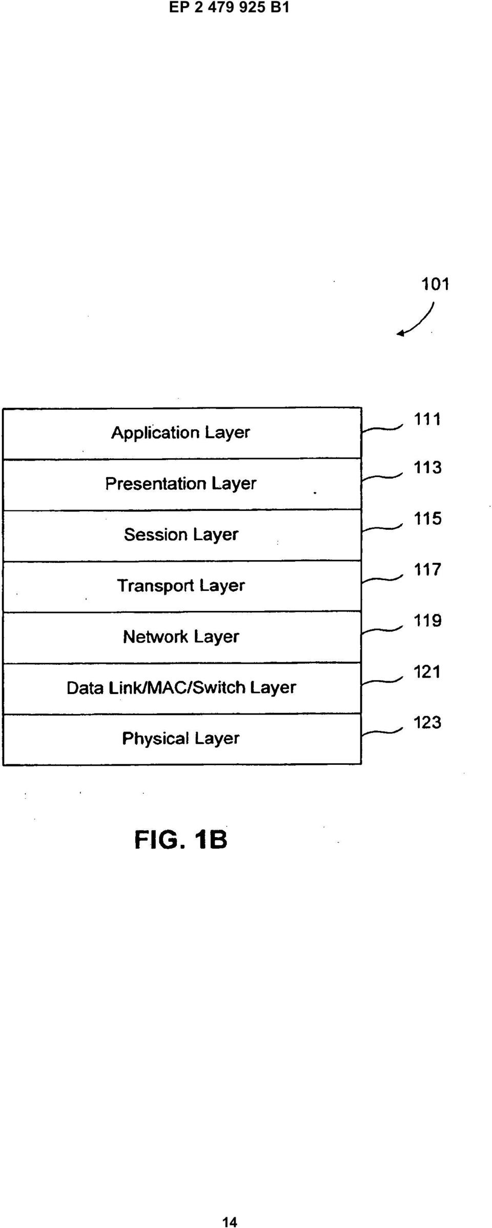
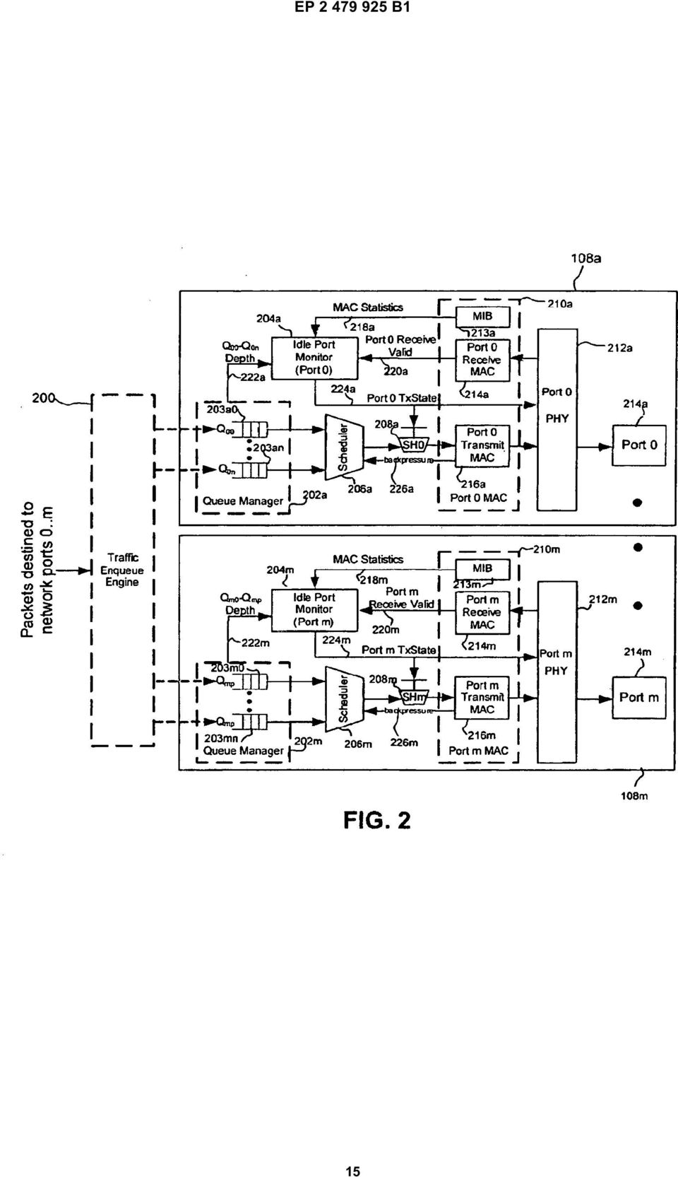
4 EP B1 6 For example, port unit 8a is coupled to device 6a. Device 6a is the link partner to port unit 8a. Similarly, port unit 8a is the link partner to device 6a. In embodiments presented herein devices 6a and port units 8 operate based on the IEEE 802.3ab protocol, but it is to be appreciated that the devices may be based on other protocols. Switch 4 includes a processor coupled to a memory 7. In an example, processor performs the power management control described herein based on instructions stored in memory 7. Embodiments presented herein provide for power management methods and systems that can be implemented in either device 6 or port units 8. Port units 8 may implement an Open System Interconnection (OSI) stack as described below with respect to FIG. 1B. [0024] FIG. 1B illustrates an example communication stack 1 according to an embodiment of the invention. [002] Communication stack 1 is a framework for implementing communication protocols in a hierarchy of seven layers: application layer 111, presentation layer 113, session layer 1, transport layer 117, network layer 119, data link layer 121 and physical layer 123. [0026] Application layer 111 allows a user to access information on a network through an application or program. Common functions at this layer are opening, closing, reading and writing files, transferring files and messages, executing remote jobs and obtaining directory information about network resources. [0027] Presentation layer 113 provides a standard interface for the application layer I 11. For data transmission between different types of computer systems, the presentation layer 113 negotiates and manages the way data is represented and encoded. [0028] Session layer 1 controls the dialogues/connections between computers. It establishes, manages and terminates connections between local applications and remote applications. [0029] Transport layer 117 provides transparent transfer of data between end users, thus relieving the upper layers from any concern while providing reliable data transfer. [00] Network layer 119 establishes the route between a sender and a receiver across switching points such as, for example, switch 4 and devices 6. An example of a network layer 119 is the Internet Protocol (IP). [0031] Data link/switch/mac layer 121 is responsible for node to node validity and integrity of the transmission. Transmitted bits are divided into frames, for example, an Ethernet or Token Ring frame in a network. [0032] Physical layer 123 transmits and receives bits from a physical medium such as, for example, twisted pair Ethernet cables. Physical layer 214 deals with electrical and mechanical characteristics of signals and signaling methods. [0033] It is a feature of the embodiments presented herein to provide the control for power management methods at a higher layer for managing power at lower layers. For example, power management software and hardware control is implemented MAC layer 121 controls the power of circuits at the PHY layer 123. In conventional system, power management for PHY layer 123 is implemented in the PHY layer 123 itself. In embodiments presented herein, the control may be implemented at any layer above the PHY layer 123. In alternate embodiments, the control for power management may be implemented in the PHY layer 123 itself. In the example presented in FIG. 1B, the communication stack 1 is an OSI stack. However, it is to be appreciated that stack 1 may be any type of communication stack for example a Systems Network Architecture (SNA) stack or an IEEE 802 stack. [0034] FIG. 2 further illustrates port units 8 of switch 4 according to an embodiment of the invention. [003] Each port unit 8 is coupled to a traffic engine 0. Each port unit 8 includes a queue manager 2, an Idle Port Monitor (IPM) 4, a MAC layer 2, a PHY layer 212, a port 214, a scheduler 6 and a shaper 8. MAC layer 2 may be the same as MAC layer 121 and PHY layer 212 may be the same as PHY layer 123 of stack 1. [0036] According to an embodiment of the invention, for each port unit 8, a corresponding IPM 4 triggers the embedded PHY 212 to enter or exit a low power mode. According to an embodiment of the invention, IPM 4 waits for a configurable time period before it engages the power-savings mode without increasing the latency through the system. [0037] Each port unit 8 has multiple queues 3a-n in a queue manager 2. Queues 3 receive packets that are buffered in queues in traffic engine 0. Packets destined to the port 214 are en-queued in queues 3an before they are transmitted out on the port 214. For example, queues 3 in queue manager 2a store data destined for transmission via port 214a. Scheduler 6 de-queues packets from the queues 3 when it is time to transmit the packets via port 214. Port shaper 8 "rate-shapes" packet transmissions by deciding when it is time to send a packet from queues 3 to transmit MAC 216 for transmission via a port 214. [0038] In an example, a "PAUSE" packet from a link partner, for example, a device 6, triggers a backpressure signal 226 that commands scheduler 6 to stop packet transmission. Independent of packet transmission, the receive MAC 214 may receive packets from a remote device, for example, a device 6, in a full-duplex link. Beginning of packet reception via port 214 may be indicated by a receive valid signal 2 that is generated by receive MAC 214. [0039] Each IPM 4 implements a control policy in hardware and/or software to trigger an embedded PHY 212 to transition in and out of a low power mode. The low power mode helps conserve power either when the PHY is in an IDLE mode and is transmitting or receiving an IDLE signal to or from a link partner 6. The "low power mode" as described herein refers to operation of 4

5 7 EP B1 8 the portions of PHY layer 212 in a manner that conserves energy while maintaining signal fidelity for transmission and reception of an IDLE signal to and from a link partner device 6. FIG. 4 illustrates the PHY layer 212 in further detail. PHY layer 212 includes a Physical Coding Sublayer (PCS) layer 2, Physical Medium Attachment (PMA) layer 4 and a Physical Medium Dependent (PMD) layer 6. In embodiments presented herein, portions of PHY 212 are selectively operated in low power mode. For example, transition state signals 224 may only trigger PMA layer 4 and PMD layer 6 into and out of the low power mode. PCS layer 2 may not be operated in low power mode. In an example, analog and digital portions of PHY 212 circuitry, except those responsible for transmission and reception of the IDLE signal, are operated in low power mode. Maintaining the fidelity of the IDLE signal allows for fast transition out of low power mode since timing and recovery circuits remain synchronized with a link partner 6 during the low power mode. In contrast, for system implementing LPI in EEE enabled systems, an additional delay is introduced in resuming transmission from an idle state due to timing recovery operations. [00] A "normal power mode" as referred to herein is when all portions of PHY 212 are operated at their normal power level. Transition state signals 224 trigger portions of PHY 212 between low power mode and normal power mode as described further herein. [0041] In an embodiment, an IPM 4 is present in each port unit 8 that supports the low power mode in the embedded PHY 212. IPM 4 may monitor several conditions in switch 4, transition from normal to low power mode, and triggers a low power mode in a corresponding embedded PHY 212. The co-ordination functions implemented by an IPM 4 are determined by a control policy implemented in IPM 4 and described below with respect to the flowchart in FIG. 3. It is to be appreciated that IPM 4 maybe implemented entirely in hardware, entirely in software or in a combination of hardware and software. [0042] In an embodiment, depending on MAC statistics signal 218, IPM 4 generates transition state signal 224 to operate PHY 212 at different levels of power savings by turning off different sections of analog & digital blocks in PHY 212. Additionally, PHY 212 may provide status signals (not shown) to IPM 4 that indicate status of PHY 212 and link quality with a link partner. These signals may be processed by IPM 4 to determine, PHY 212 conditions which may be incorporated into a power control policy of IPM 4. As a result, the system can achieve different levels of power savings along with a robust performance. [0043] According to an embodiment of the invention, IPM 4 may perform the following functions: [0044] - collect traffic statistics and detect when a port has not been transmitting for some amount of time and transition it to a low power mode, [004] - stop data transmission on the link, [0046] - trigger the PHY 212 to enter a low power mode, [0047] - detect when there is enough data to transmit in queues 3, [0048] - trigger the PHY 212 to come out of the low power mode, and [0049] - re-start data transmission to a link partner. [000] According to an embodiment of the invention, IPM 4 is configured to generate transition state signal 224 to transition PHY 212 between low power mode and normal power mode. According to an embodiment of the invention, transition state signal 224 places PHY 212 in low power mode based on one or more queue depth signals 222 as described below with respect to the flowchart in FIG. 3. In an example embodiment, transition state signal 224 places PHY 212 in a low power mode based on MAC statistics signal 218 received from MIB unit 213 in MAC 2. MAC statistics signal 218 indicates transmit and receive statistics of port 214. The transmit statistics are the number of packets transmitted via a port 214 and the receive statistics are the number of packets received via a port 214. In an example, if the transmit and receive statistics indicate that port 214 does not transmit or receive data during certain time periods of a day (for example during nighttime), then IPM 4 places PHY 212 into low power mode during the periods of inactivity. In another example, if MAC statistics signal 218 indicates that data is only received during certain periods then IPM 4 places only the transmit portions of PHY 212 circuitry into low power mode during these periods. [001] According to an embodiment of the invention, transition state signal 214 transitions PHY 212 from low power mode into normal power mode based on queue depth signals 222 and receive valid signal 2 as described below with respect to the algorithm in FIG. 3. The receive valid signal 2 generated by receive MAC 214 indicates the receipt of data via port 214. [002] FIG. 3 illustrates an example flowchart 0 showing steps performed to transition PHY 212 between a low power mode and a normal power mode according to an embodiment of the invention. Flowchart 0 will be described with continued reference to the example operating environment depicted in FIGs However, the flowchart is not limited to these embodiments. Note that some steps shown in flowchart 0 do not necessarily have to occur in the order shown. The steps in flow chart 0 may be performed by, for example, by idle port manager 4. [003] In step 2, the system is in normal power mode. For example, PHY 212 is operating in normal power mode. [004] In step 4, queue depth signals are monitored once every pre-determined period of time. For example, IPM 4 periodically monitors queue depth signals every k microseconds. The minimum value of k may depend on specific hardware and software implementation and may be determined by the time required to monitor queue depth signals 222. [00] In step 6, it is determined whether transmit

6 9 EP B1 queues are empty for a predetermined number of times. For example, IPM 4 determines whether transmit queues 3 are empty m or more times. [006] If the transmit queues are not empty for the predetermined number of times then the process proceeds to step 2 where the system is continued to be operated in normal power mode. [007] If transmit queues are empty for a pre-determined number of times, then the process proceeds to step 8. [008] In step 8, de-queuing of data is stopped. For example, transition state signal 8 causes traffic shaper 8 to stop de-queuing data from transmit queues 3. [009] In step 312, the PHY is transitioned to a low power mode. For example, IPM 4 generates transition state signal 224 to transition PHY 212 to a low power mode. [0060] In step 314, the system waits for a second predetermined period of time before the next step. For example, IPM 4 waits for "g" microseconds before executing step 316. The wait time of g microseconds may be based on a latency to complete a transition from a normal power mode to a low power mode. [0061] In step 316, queue depth signals and a receive valid signal are monitored every third pre-determined period of time. For example, IPM 4 monitors queue depth signals 222 and receive valid signal 2 every "p" microseconds. The minimum value of p may depend on specific hardware and software implementation of switch 4 and may be determined by the time required to monitor queue depth of multiple transmit queues 3 that are dedicated to a port 214. In another example, IPM 4 only monitors queue depth signal 2 and does not monitor receive valid signal 2. [0062] In step 318, it is determined whether the low power mode is to be exited. For example, if the queue depth signals 222 indicate that the transmit queues 3 are empty and if receive valid signal 2 indicates that no data is being received via port 214, then the process proceeds to step 316. If queue depth signals 222 indicate that data is ready for transmission in one or more transmit queues 3 or if receive valid signal 2 indicates that data is coming in via port 214, then the process proceeds to step 3. [0063] In step 3, the system if transitioned back to normal power mode. For example, IPM 4 generates transition state signal 224 to transition PHY 212 and traffic shaper 8 from low power mode to normal power mode. Transition signal 224 also transitions traffic shaper 8 from low power mode to normal power mode. [0064] In step 322, the system waits for a fourth predetermined period of time before the next step. For example, IPM 4 waits for "r" microseconds before executing step 324. In an example, the system waits for the fourth pre-determined period of time to allow for data to build up in transmit queues 3 prior to de-queuing data for transmission. The value r may depend on a latency to transition PHY 212 from low power mode to normal power mode. [006] In step 324, data is de-queued from transmit queues. For example, data is de-queued by scheduler 6 from transmit queues 3 and shaped by traffic shaper 8 for transmission via port 214. The process proceeds to step 4. [0066] The variables k, m, p, q, and r described above may be arbitrary values that can be configured dynamically during operation in real time or can be pre-set prior to system startup. [0067] Embodiments presented herein, or portions thereof, can be implemented in hardware, firmware, software, and/or combinations thereof. The embodiments presented herein apply to any communication system that uses authentication procedures for any type of service. [0068] The representative functions described herein, for example, by IPM 4 or switch 4 can be implemented in hardware, software, or some combination thereof. For instance, the method of flowchart 0 can be implemented using one or more computer processors, such as processor based on instruction stored in memory 7, computer logic, application specific circuits (ASIC), digital signal processors, etc., or any combination thereof, as will be understood by those skilled in the arts based on the discussion given herein. Accordingly, any processor that performs the functions described herein is within the scope and spirit of the embodiments presented herein. [0069] Further, the processing functions described herein could be embodied by computer program instructions that are executed by a computer processor, for example processor based on instructions stored in memory 7, or any one of the hardware devices described herein. The computer program instructions cause the processor to perform the instructions described herein. The computer program instructions (e.g. software) can be stored in a computer usable medium, computer program medium, or any storage medium that can be accessed by a computer or processor. Such media include a memory device, such as memory 7, a RAM or ROM, or other type of computer storage medium such as a computer disk or CD ROM, or the equivalent. Accordingly, any computer storage medium having computer program code that cause a processor to perform the functions described herein are within the scope and spirit of the embodiments presented herein. Conclusion [0070] While various embodiments have been described above, it should be understood that they have been presented by way of example, and not limitation. It will be apparent to persons skilled in the relevant art that various changes in form and detail can be made therein without departing from the scope of the embodiments presented herein. [0071] The embodiments presented herein have been 6
![[007] If transmit queues are empty for a pre-determined number of times, then the process proceeds to step 8. [008] In step 8, de-queuing of data is stopped.](/docs-images/44/16613383/images/page_6.jpg "For example, transition state signal 8 causes traffic shaper 8 to stop de-queuing data from transmit queues 3. [009] In step 312, the PHY is transitioned to a low power mode.")
7 11 EP B1 12 described above with the aid of functional building blocks and method steps illustrating the performance of specified functions and relationships thereof. The boundaries of these functional building blocks and method steps have been arbitrarily defined herein for the convenience of the description. Alternate boundaries can be defined so long as the specified functions and relationships thereof are appropriately performed. Any such alternate boundaries are thus within the scope of the claimed embodiments. One skilled in the art will recognize that these functional building blocks can be implemented by discrete components, application specific integrated circuits, processors executing appropriate software and the like or any combination thereof. Thus, the breadth and scope of the present embodiments should not be limited by any of the above-described exemplary embodiments, but should be defined only in accordance with the following claims and their equivalents. [0072] It is to be appreciated that the Detailed Description section, and not the Abstract section, is intended to be used to interpret the claims. The Abstract section may set forth one or more but not all exemplary embodiments of the present invention as contemplated by the inventor(s), and thus, are not intended to limit the present invention and the appended claims in any way. [0073] The foregoing description of the specific embodiments will so fully reveal the general nature of the invention that others can, by applying knowledge within the skill of the art, readily modify and/or adapt for various applications such specific embodiments, without undue experimentation, without departing from the general concept of the present invention. Therefore, such adaptations and modifications are intended to be within the meaning and range of equivalents of the disclosed embodiments, based on the teaching and guidance presented herein. It is to be understood that the phraseology or terminology herein is for the purpose of description and not of limitation, such that the terminology or phraseology of the present specification is to be interpreted by the skilled artisan in light of the teachings and guidance. [0074] The breadth and scope of the present invention should not be limited by any of the above-described exemplary embodiments, but should be defined only in accordance with the following claims and their equivalents. Claims MAC layer (121, 2); and generate a transition state signal, based on the received MAC statistics signal (218), that selectively causes portions of the PHY (123, 212) to operate in a low power mode based on whether the port (8) is active. 2. The system of claim 1, wherein said portions of the PHY (123, 212) are adapted to operate in a manner that conserves energy while maintaining ability for transmission and reception of an idle signal to and from the port (8). 3. The system of claim 1, further comprising a queue manager (2) that includes a plurality of transmit queues, wherein the queue manager (2) is configured to send a queue depth signal to the idle port monitor (4) to indicate whether one or more queues (3) have data for transmission. 4. The system of claim 3, wherein the idle port monitor (4) is configured to determine that the port (8) is active if the queue depth signal indicates that a queue has data for transmission and to determine that the port (8) is inactive if the queue depth signal indicates that no queue has data for transmission.. The system of claim 3, wherein the idle port monitor (4) is configured to, monitor the queue depth signal once every first pre-determined period of time, determine whether the transmit queues (3) are empty for a pre-determined number of times based on the queue depth signal and generate the transition state signal to operate portions of the PHY (123, 212) in low power mode. 6. The system of claim, wherein the idle port monitor (4) is configured to wait a second pre-determined period of time and monitor a receive valid signal (2) from the MAC layer (121, 2) and the queue depth signal every third pre-determined period of time and send the transition state signal to the PHY (123, 212) to operate the PHY (123, 212) in a normal mode if the receive valid signal (2) indicates receipt of data via the port (8) or the queue depth signal indicates that one or more transmit queues (3) has data to transmit. 1. A system to dynamically manage power in a communication system (4), comprising: a port (8) to transmit and receive data; a Media Access Control, MAC, layer (121, 2); a physical layer, PHY, (123, 212) coupled to the port (8); and an idle port monitor (4) coupled to the port (8) and the PHY (123, 212) and configured to receive a MAC statistics signal (218) from the 0 7. The system of claim 1, further comprising: a traffic shaper configured to de-queue data from transmit queues (3) if the transition state signal indicates a normal power mode and to stop de-queuing data from the transmit queues (3) if the transition state signal indicates a low power mode. 8. The system of claim 1, wherein the idle port monitor 7

8 13 EP B1 14 (4) is implemented in a layer of a communication stack that is higher than the PHY layer (123, 212). 9. The system of claim 1, wherein said MAC layer (121, 2) includes: a receive MAC unit (214) configured to send a receive valid signal (2) to the idle port monitor (4) to indicate receipt of data via the port (8) from a link partner (6); and a statistical unit configured to send transmit and receive statistics to the idle port monitor (4), wherein the transmit statistics are the number of packets transmitted via the port (8) and the receive statistics are the number of packets received via the port (8); wherein the idle port monitor (4) is configured to selectively place portions of the PHY (123, 212) into low power mode or a normal mode based on the receive valid signal (2), the transmit and receive statistics and a queue depth signal that indicates whether data is present in transmit queues (3) for transmission.. The system of claim 1, wherein in the low power mode, selective portions of a Physical Medium Attachment, PMA, layer and a Physical Medium Dependent, PMD, layer of the PHY layer (123, 212) are operated using low power. 2 de-queing of data from the transmit queue if the transmit data queue is empty for the pre-determined number of times; and selectively operating portions of a Physical Layer, PHY, (123, 212) in a low power mode that are used for functions other than transmitting and receiving an idle signal in a low power mode based on the generating of the transition state signal. 14. The method of claim 13, further comprising operating portions of the PHY layer (123, 212) in low power mode if no data is being received via a port (8).. The method of claim 13, further comprising operating portions of the PHY layer (123, 212) in a manner that conserves energy while maintaining ability for transmission and reception of an idle signal to and from the port (8). 16. The method of claim 13, 14 or, after the selectively operating step, further comprising monitoring the transmit queue once every second pre-determined period of time to determine whether the transmit queue has data for transmission. 17. The method of claim 16, further comprising monitoring a receive valid signal (2) once every second pre-determined period of time to determine whether data is being received via the port (8). 11. The system of claim 1, wherein in the low power mode, analog and digital portions of the PHY (123, 212) that transmit or receive an idle signal from the link partner (6) are operated in normal power mode and other analog and digital portions of the PHY (123, 212) are operated in low power mode. 12. The system of claim 1, wherein the PHY (123, 212) is adapted to provide status signals to the idle port monitor (4) that indicate status of PHY (123, 212) and link quality with a link partner, and these signals are processed by the idle port monitor (4) to determine conditions of the PHY (123, 212) to be incorporated into a power control policy of idle port monitor (4). 13. A method for dynamic power management in a communication system (4), comprising: monitoring a transmit data queue every pre-determined period of time; determining whether the transmit data queue is empty for a pre-determined number of times within the pre-determined period of time; receiving a MAC statistics signal (218); and generating a transition state signal, based on the received MAC statistics signal (218), to stop The method of claim 17, further comprising generating the transition state signal to cause the portions of the PHY layer (123, 212) operating in low power mode to operate in a normal power mode if the transmit queue has data for transmission or if the receive valid signal (2) indicates that data is being received via the port (8). Patentansprüche 1. System zum dynamischen Verwalten von Energie in einem Kommunikationssystem (4), das aufweist: einen Port (8) zum Senden und Empfangen von Daten; eine Media Access Control, MAC, -Schicht (121, 2); eine physikalische Schicht (physical layer; PHY) (123, 212), die an den Port (8) gekoppelt ist; und eine Leerlaufport-Überwachungseinrichtung (4), die an den Port (8) und die PHY (123, 212) gekoppelt und dazu konfiguriert ist, ein MAC-Statistiksignal (218) von der MAC-Schicht (121, 2) zu empfangen; und basierend auf dem empfangenen MAC-Statis- 8
 from a link partner (6); and a statistical unit configured to send transmit and receive statistics to the idle port monitor (4), wherein the transmit statistics are the number of packets")
9 EP B1 16 tiksignal (218) ein Übergangszustandssignal zu erzeugen, das selektiv veranlasst, dass Teile der PHY (123, 212) in einem Niedrigenergiemodus arbeiten, basierend darauf, ob der Port (8) aktiv ist. 2. System nach Anspruch 1, wobei die Teile der PHY (123, 212) dazu ausgelegt sind, auf eine Art und Weise zu arbeiten, die Energie spart, während die Fähigkeit zum Senden und Empfangen eines Leerlaufsignals an und von dem Port (8) beibehalten wird. 3. System nach Anspruch 1, das des Weiteren einen Warteschlangen-Manager (2) aufweist, der eine Vielzahl von Sendewarteschlangen aufweist, wobei der Warteschlangen-Manager (2) dazu konfiguriert ist, ein Warteschlangentiefensignal an die Leerlaufport-Überwachungseinrichtung (4) zu senden, um anzuzeigen, ob eine oder mehrere Warteschlangen (3) Daten zum Senden haben. 4. System nach Anspruch 3, wobei die Leerlaufport- Überwachungseinrichtung (4) dazu konfiguriert ist zu bestimmen, dass der Port (8) aktiv ist, wenn das Warteschlangentiefensignal angibt, dass eine Warteschlange Daten zum Senden hat, und zu bestimmen, dass der Port (8) inaktiv ist, wenn das Warteschlangentiefensignal angibt, dass keine Warteschlange Daten zum Senden hat.. System nach Anspruch 3, wobei die Leerlaufport- Überwachungseinrichtung (4) dazu konfiguriert ist, das Warteschlangentiefensignal einmal pro vorgegebener Zeitdauer zu überwachen, zu bestimmen, ob die Sendewarteschlangen (3) für eine vorgegebene Anzahl von Zeiten leer sind, basierend auf dem Warteschlangentiefensignal, und das Übergangszustandssignal zu erzeugen, um Teile der PHY (123, 212) in einem Niedrigenergiemodus zu betreiben. 2 3 einen Verkehrsformer, der dazu konfiguriert ist, Daten aus Sendewarteschlangen (3) zu entnehmen, wenn das Übergangszustandssignal einen Normalenergiemodus anzeigt, und das Entnehmen von Daten aus den Sendewarteschlangen (3) zu stoppen, wenn das Übergangszustandssignal einen Niedrigenergiemodus anzeigt. 8. System nach Anspruch 1, wobei die Leerlaufport- Überwachungseinrichtung (4) in einer Schicht eines Kommunikationsstapels implementiert ist, die höher ist, als die PHY-Schicht (123, 212). 9. System nach Anspruch 1, wobei die MAC-Schicht (121, 2) aufweist: eine MAC-Empfangseinheit (214), die dazu konfiguriert ist, ein gültiges Empfangssignal (2) an die Leerlaufport-Überwachungseinrichtung (4) zu senden, um den Empfang von Daten über den Port (8) von einem Verbindungspartner (6) anzuzeigen; und eine Statistikeinheit, die dazu konfiguriert ist, Sende- und Empfangsstatistiken an die Leerlaufport-Überwachungseinrichtung (4) zu senden, wobei die Sendestatistiken die Anzahl von Paketen sind, die über den Port (8) gesendet werden, und die Empfangsstatistiken die Anzahl von Paketen sind, die über den Port (8) empfangen werden; wobei die Leerlaufport-Überwachungseinrichtung (4) dazu konfiguriert ist, selektiv Teile der PHY (123, 212) in einen Niedrigenergiemodus oder einen Normalmodus zu versetzen, basierend auf dem gültigen Empfangssignal (2), den Sende- und Empfangsstatistiken und einem Warteschlangentiefensignal, das anzeigt, ob Daten in Sendewarteschlangen (3) zum Senden vorhanden sind. 6. System nach Anspruch, wobei die Leerlaufport- Überwachungseinrichtung (4) dazu konfiguriert ist, einen zweiten vorgegebenen Zeitraum zu warten und ein gültiges Empfangssignal (2) von der MAC- Schicht (121, 2) und das Warteschlangentiefensignal pro dritter vorgegebener Zeitdauer zu überwachen und das Übergangszustandssignal an die PHY (123, 212) zu senden, um die PHY (123, 212) in einem Normalmodus zu betreiben, wenn das gültige Empfangssignal (2) Empfang von Daten über den Port (8) anzeigt oder das Warteschlangentiefensignal anzeigt, dass eine oder mehrere Sendeschlangen (3) Daten zum Senden haben. 7. System nach Anspruch 1, das des Weiteren aufweist: 4 0. System nach Anspruch 1, wobei im Niedrigenergiemodus selektive Teile einer Physical Medium Attachment, PMA, -Schicht und einer Physical Medium Dependent, PMD, -Schicht der PHY-Schicht (123, 212) unter Verwendung von Niedrigenergie betrieben werden. 11. System nach Anspruch 1, wobei im Niedrigenergiemodus analoge und digitale Teile der PHY (123, 212), die ein Leerlaufsignal von dem Verbindungspartner (6) senden oder empfangen, im Normalenergiemodus betrieben werden, und andere analoge und digitale Teile der PHY (123, 212) im Niedrigenergiemodus betrieben werden. 12. System nach Anspruch 1, wobei die PHY (123, 212) dazu ausgelegt ist, Statussignale an die Leerlauf- 9
 beibehalten wird. 3.")
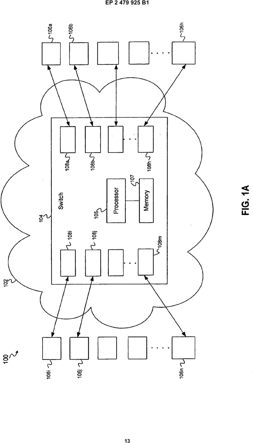
10 17 EP B1 18 port-überwachungseinrichtung (4) zu senden, die den Status der PHY (123, 212) und die Verbindungsqualität mit einem Verbindungspartner angeben, und wobei diese Signale von der Leerlaufport-Überwachungseinrichtung (4) verarbeitet werden, um die Zustände der PHY (123, 212) zu ermitteln, die in eine Energiesteuerungsstrategie der Leerlaufport- Überwachungseinrichtung (4) einzubauen sind. 18. Verfahren nach Anspruch 17, das des Weiteren das Erzeugen des Übergangszustandssignals umfasst, um zu veranlassen, dass die Teile der PHY-Schicht (123, 212), die im Niedrigenergiemodus arbeiten, in einem Normalenergiemodus arbeiten, wenn die Sendewarteschlange Daten zum Senden hat, oder wenn das gültige Empfangssignal (2) anzeigt, dass Daten über den Port (8) empfangen werden. 13. Verfahren zum dynamischen Verwalten von Energie in einem Kommunikationssystem (4), das umfasst: Überwachen einer Sendedatenschlange pro vorgegebenen Zeitraum; Bestimmen, ob die Sendewarteschlange für eine vorgegebene Anzahl von Zeiten innerhalb des vorgegebenen Zeitraums leer ist; Empfangen eines MAC-Statistiksignals (218); und Erzeugen eines Übergangszustandssignals basierend auf dem empfangenen MAC-Statistiksignal (218), um das Entnehmen von Daten aus der Sendewarteschlange zu stoppen, wenn die Sendedatenschlange für die vorgegebene Anzahl von Zeiten leer ist; und selektives Betreiben von Teilen einer physikalischen Schicht (physical layer; PHY) in einem Niedrigenergiemodus, die für andere Funktionen als für das Senden und Empfangen eines Leerlaufsignals in einem Niedrigenergiemodus verwendet werden, basierend auf dem Erzeugen des Übergangszustandssignals. 14. Verfahren nach Anspruch 13, das des Weiteren das Betreiben von Teilen der PHY-Schicht (123, 212) im Niedrigenergiemodus umfasst, wenn keine Daten über einen Port (8) empfangen werden.. Verfahren nach Anspruch 13, das das Weiteren das Betreiben von Teilen der PHY-Schicht (123, 212) auf eine Art und Weise, die Energie spart, umfasst, während die Fähigkeit des Sendens und Empfangens eines Leerlaufsignals an den und von dem Port (8) beibehalten wird. 16. Verfahren nach Anspruch 13, 14 oder, das, nach dem Schritt des selektiven Betreibens, des Weiteren das Überwachen der Sendewarteschlange einmal pro zweiten vorgegebenen Zeitraum umfasst, um zu bestimmen, ob die Sendewarteschlange Daten zum Senden hat. 17. Verfahren nach Anspruch 16, das des Weiteren das Überwachen eines gültigen Empfangssignals (2) einmal pro zweiten vorgegebenen Zeitraum umfasst, um zu bestimmen, ob Daten über den Port (8) empfangen werden Revendications 1. Système de gestion dynamique de consommation d énergie dans un système de communication (4), comprenant : un port (8) pour transmettre et recevoir des données ; une couche (121, 2) de contrôle d accès au support, MAC ; une couche (123, 212) physique, PHY, couplée au port (8) ; et un moniteur (4) de port en veille couplé au port (8) et à la PHY (123, 212) et configuré pour recevoir un signal (218) de statistiques MAC de la couche MAC (121, 2) ; et générer un signal d état de transition, sur la base du signal (218) de statistiques MAC reçu, qui fait sélectivement que des parties de la PHY (123, 212) fonctionnent dans un mode basse consommation d énergie sur la base que le port (8) est ou non actif. 2. Système selon la revendication 1, dans lequel lesdites parties de la PHY (123, 212) sont adaptées à fonctionner d une manière qui conserve de l énergie tout en maintenant une capacité de transmission et de réception d un signal de veille vers le et du port (8). 3. Système selon la revendication 1, comprenant en outre un gestionnaire (2) de files d attente qui inclut une pluralité de files d attente de transmission, dans lequel le gestionnaire (2) de files d attente est configuré pour envoyer un signal de profondeur de files d attente au moniteur (4) de port en veille pour indiquer si une ou plusieurs file(s) d attente (3) a/ont des données pour transmission. 4. Système selon la revendication 3, dans lequel le moniteur (4) de port en veille est configuré pour déterminer que le port (8) est actif si le signal de profondeur de files d attente indique qu une file d attente a des données pour transmission et pour déterminer que le port (8) est inactif si le signal de profondeur de files d attente indique qu aucune file d attente n a des données pour transmission.
, die im Niedrigenergiemodus arbeiten, in")
11 19 EP B1. Système selon la revendication 3, dans lequel le moniteur (4) de port en veille est configuré pour surveiller le signal de profondeur de files d attente une fois à chaque première période de temps prédéterminée, déterminer si les files d attente (3) de transmission sont vides un nombre de fois prédéterminé sur la base du signal de profondeur de files d attente et générer le signal d état de transition pour faire fonctionner des parties de la PHY (123, 212) en mode basse consommation. 6. Système selon la revendication, dans lequel le moniteur (4) de port en veille est configuré pour attendre une deuxième période de temps prédéterminée et surveiller un signal (2) valide de réception de la couche MAC (121, 2) et le signal de profondeur de files d attente à chaque troisième période de temps prédéterminée et envoyer le signal d état de transition à la PHY (123, 212) pour faire fonctionner la PHY (123, 212) dans un mode normal si le signal (2) valide de réception indique une réception de données par l inter-médiaire du port (8) ou si le signal de profondeur de files d attente indique qu une ou plusieurs file(s) d attente (3) de transmission a/ont des données à transmettre. 7. Système selon la revendication 1, comprenant en outre : un metteur en forme de trafic configuré pour retirer des données de files d attente (3) de transmission si le signal d état de transition indique un mode de consommation d énergie normal et pour arrêter de retirer des données de files d attente (3) de transmission si le signal d état de transition indique un mode basse consommation d énergie. 8. Système selon la revendication 1, dans lequel le moniteur (4) de port en veille est mis en oeuvre dans une couche d une pile de communication qui est supérieure à la couche PHY (123, 212). 9. Système selon la revendication 1, dans lequel ladite couche MAC (121, 2) inclut : nombre de paquets reçus par l intermédiaire du port (8) ; dans lequel le moniteur (4) de port en veille est configuré pour placer sélectivement des parties de la PHY (123, 212) en mode basse consommation d énergie ou en un mode normal sur la base du signal (2) valide de réception, des statistiques de transmission et de réception et d un signal de profondeur de files d attente qui indique si des données sont présentes dans des files d attente (3) de transmission pour transmission.. Système selon la revendication 1, dans lequel, dans le mode basse consommation d énergie, des parties sélectives d une couche de raccordement au support physique, PMA, et d une couche dépendant du support physique, PMD, de la couche PHY (123, 212) fonctionnent en utilisant une basse consommation d énergie. 11. Système selon la revendication 1, dans lequel, dans le mode basse consommation d énergie, des parties analogiques et numériques de la PHY (123, 212) qui transmettent ou reçoivent un signal de veille du partenaire (6) de liaison fonctionnent en mode de consommation d énergie normale et d autres parties analogiques et numériques de la PHY (123, 212) fonctionnent en mode basse consommation d énergie. 12. Système selon la revendication 1, dans lequel la PHY (123, 212) est adaptée à délivrer des signaux de statut au moniteur (4) de port en veille qui indiquent un statut de la PHY (123, 212) et une qualité de liaison avec un partenaire de liaison, et ces signaux sont traités par le moniteur (4) de port en veille pour déterminer des conditions de la PHY (123, 212) destinées à être incorporées dans une politique de contrôle de consommation d énergie de moniteur (4) de port en veille. 13. Procédé de gestion dynamique de consommation d énergie dans un système de communication (4), comprenant : une unité (214) MAC de réception configurée pour envoyer un signal (2) valide de réception au moniteur (4) de port en veille pour indiquer une réception de données par l intermédiaire du port (8) en provenance d un partenaire (6) de liaison ; et une unité statistique configurée pour envoyer des statistiques de transmission et de réception au moniteur (4) de port en veille, dans lequel les statistiques de transmission sont le nombre de paquets transmis par l intermédiaire du port (8) et les statistiques de réception sont le 0 la surveillance d une file d attente de données de transmission à chaque période de temps prédéterminée ; la détermination si la file d attente de données de transmission est vide un nombre de fois prédéterminé au sein de la période de temps prédéterminée ; la réception d un signal (218) de statistiques MAC ; et la génération d un signal d état de transition, sur la base du signal (218) de statistiques MAC reçu, pour arrêter de retirer des données de la file 11
 en mode basse consommation. 6.")
12 21 EP B1 22 d attente de transmission si la file d attente de données de transmission est vide le nombre de fois prédéterminé ; et le fonctionnement sélectif de parties d une couche physique, PHY (123, 212), dans un mode basse consommation, qui sont utilisées pour des fonctions autres que la transmission et la réception d un signal de veille dans un mode basse consommation sur la base de la génération du signal d état de transition. 14. Procédé selon la revendication 13, comprenant en outre le fonctionnement de parties de la couche PHY (123, 212) en mode basse consommation si aucune donnée n est reçue par l intermédiaire d un port (8).. Procédé selon la revendication 13, comprenant en outre le fonctionnement de parties de la couche PHY (123, 212) d une manière qui conserve de l énergie tout en maintenant une capacité de transmission et de réception d un signal de veille vers le et du port (8). 16. Procédé selon la revendication 13, 14 ou, après l étape de fonctionnement sélectif, comprenant en outre la surveillance de la file d attente de transmission une fois à chaque deuxième période de temps prédéterminée pour déterminer si la file d attente de transmission a des données pour transmission Procédé selon la revendication 16, comprenant en outre la surveillance d un signal (2) valide de réception une fois à chaque deuxième période de temps prédéterminée pour déterminer si des données sont reçues par l intermédiaire du port (8) Procédé selon la revendication 17, comprenant en outre la génération du signal d état de transition pour faire en sorte que les parties de la couche PHY (123, 212) fonctionnant en mode basse consommation fonctionnent dans un mode de consommation normale si la file d attente de transmission a des données pour transmission ou si le signal (2) valide de réception indique que des données sont reçues par l intermédiaire du port (8)
 en mode basse consommation si aucune donnée n est reçue par l intermédiaire d un port")
13 EP B1 13
14 EP B1 14
15 EP B1
16 EP B1 16
17 EP B1 17

18 EP B1 REFERENCES CITED IN THE DESCRIPTION This list of references cited by the applicant is for the reader s convenience only. It does not form part of the European patent document. Even though great care has been taken in compiling the references, errors or omissions cannot be excluded and the EPO disclaims all liability in this regard. Patent documents cited in the description EP A [0003] 18

(51) Int Cl.: B29C 41/20 (2006.01) F21S 4/00 (2006.01) H05K 3/28 (2006.01)
 Int Cl.: B29C 41/20 (2006.01) F21S 4/00 (2006.01) H05K 3/28 (2006.01)") (19) TEPZZ 68698B_T (11) EP 2 68 698 B1 (12) EUROPEAN PATENT SPECIFICATION (4) Date of publication and mention of the grant of the patent: 18.11.201 Bulletin 201/47 (21) Application number: 11808612.3
(19) TEPZZ 68698B_T (11) EP 2 68 698 B1 (12) EUROPEAN PATENT SPECIFICATION (4) Date of publication and mention of the grant of the patent: 18.11.201 Bulletin 201/47 (21) Application number: 11808612.3
(51) Int Cl.: G10L 15/26 (2006.01)
 Int Cl.: G10L 15/26 (2006.01)") (19) TEPZZ Z 8B_T (11) EP 2 023 338 B1 (12) EUROPEAN PATENT SPECIFICATION (4) Date of publication and mention of the grant of the patent: 28.0.14 Bulletin 14/22 (1) Int Cl.: GL /26 (06.01) (21) Application
(19) TEPZZ Z 8B_T (11) EP 2 023 338 B1 (12) EUROPEAN PATENT SPECIFICATION (4) Date of publication and mention of the grant of the patent: 28.0.14 Bulletin 14/22 (1) Int Cl.: GL /26 (06.01) (21) Application
TEPZZ_768 7_B_T EP 1 768 371 B1 (19) (11) EP 1 768 371 B1 (12) EUROPEAN PATENT SPECIFICATION. (51) Int Cl.: H04M 19/04 (2006.01)
 (11) EP 1 768 371 B1 (12) EUROPEAN PATENT SPECIFICATION. (51) Int Cl.: H04M 19/04 (2006.01)") (19) TEPZZ_768 7_B_T (11) EP 1 768 371 B1 (12) EUROPEAN PATENT SPECIFICATION (4) Date of publication and mention of the grant of the patent: 1.01.2014 Bulletin 2014/03 (1) Int Cl.: H04M 19/04 (2006.01)
(19) TEPZZ_768 7_B_T (11) EP 1 768 371 B1 (12) EUROPEAN PATENT SPECIFICATION (4) Date of publication and mention of the grant of the patent: 1.01.2014 Bulletin 2014/03 (1) Int Cl.: H04M 19/04 (2006.01)
(51) Int Cl.: H04L 12/56 (2006.01)
 Int Cl.: H04L 12/56 (2006.01)") (19) (11) EP 1 779 90 B1 (12) EUROPEAN PATENT SPECIFICATION (4) Date of publication and mention of the grant of the patent: 28.12.11 Bulletin 11/2 (21) Application number: 0783482.2 (22) Date of filing:
(19) (11) EP 1 779 90 B1 (12) EUROPEAN PATENT SPECIFICATION (4) Date of publication and mention of the grant of the patent: 28.12.11 Bulletin 11/2 (21) Application number: 0783482.2 (22) Date of filing:
(51) Int Cl.: G06F 9/455 (2006.01) G06F 9/50 (2006.01)
 Int Cl.: G06F 9/455 (2006.01) G06F 9/50 (2006.01)") (19) TEPZZ 6987 B_T (11) EP 2 698 711 B1 (12) EUROPEAN PATENT SPECIFICATION (4) Date of publication and mention of the grant of the patent: 0.08.1 Bulletin 1/32 (21) Application number: 118777.8 (22) Date
(19) TEPZZ 6987 B_T (11) EP 2 698 711 B1 (12) EUROPEAN PATENT SPECIFICATION (4) Date of publication and mention of the grant of the patent: 0.08.1 Bulletin 1/32 (21) Application number: 118777.8 (22) Date
(51) Int Cl.: G06F 13/38 (2006.01) G06F 1/16 (2006.01)
 Int Cl.: G06F 13/38 (2006.01) G06F 1/16 (2006.01)") (19) TEPZZ 9777B_T (11) EP 2 97 77 B1 (12) EUROPEAN PATENT SPECIFICATION (4) Date of publication and mention of the grant of the patent: 1.07.1 Bulletin 1/29 (1) Int Cl.: G06F 13/38 (06.01) G06F 1/16 (06.01)
(19) TEPZZ 9777B_T (11) EP 2 97 77 B1 (12) EUROPEAN PATENT SPECIFICATION (4) Date of publication and mention of the grant of the patent: 1.07.1 Bulletin 1/29 (1) Int Cl.: G06F 13/38 (06.01) G06F 1/16 (06.01)
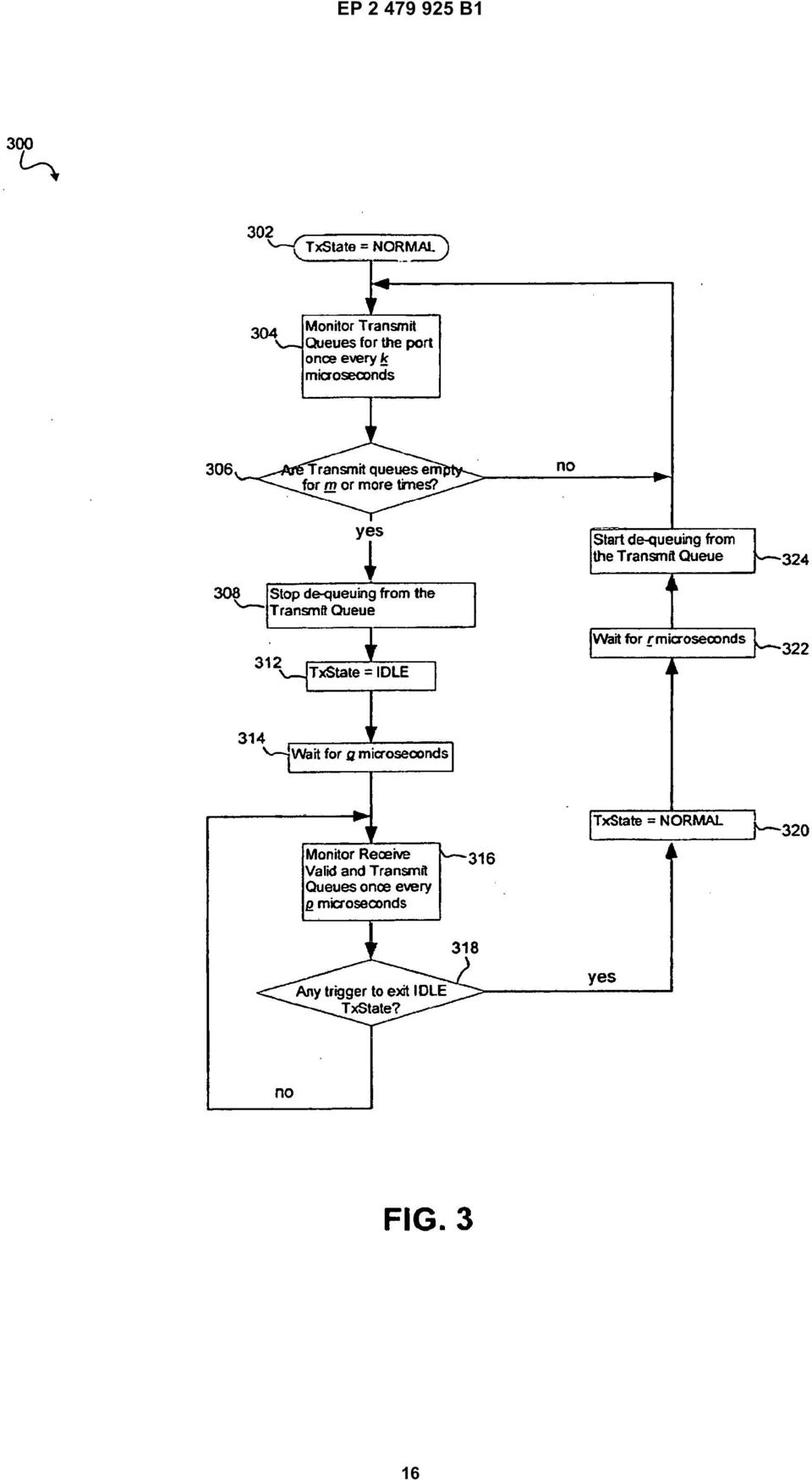
*EP001173363B1* EP 1 173 363 B1 (19) (11) EP 1 173 363 B1 (12) EUROPEAN PATENT SPECIFICATION
 (11) EP 1 173 363 B1 (12) EUROPEAN PATENT SPECIFICATION") (19) Europäisches Patentamt European Patent Office Office européen des brevets *EP001173363B1* (11) EP 1 173 363 B1 (12) EUROPEAN PATENT SPECIFICATION (4) Date of publication and mention of the grant of
(19) Europäisches Patentamt European Patent Office Office européen des brevets *EP001173363B1* (11) EP 1 173 363 B1 (12) EUROPEAN PATENT SPECIFICATION (4) Date of publication and mention of the grant of
EP 2 455 926 A1 (19) (11) EP 2 455 926 A1 (12) EUROPEAN PATENT APPLICATION. (43) Date of publication: 23.05.2012 Bulletin 2012/21
 (11) EP 2 455 926 A1 (12) EUROPEAN PATENT APPLICATION. (43) Date of publication: 23.05.2012 Bulletin 2012/21") (19) (12) EUROPEAN PATENT APPLICATION (11) EP 2 4 926 A1 (43) Date of publication: 23.0.2012 Bulletin 2012/21 (21) Application number: 11190024.7 (1) Int Cl.: G08B 2/14 (2006.01) G08B 2/00 (2006.01) G0B
(19) (12) EUROPEAN PATENT APPLICATION (11) EP 2 4 926 A1 (43) Date of publication: 23.0.2012 Bulletin 2012/21 (21) Application number: 11190024.7 (1) Int Cl.: G08B 2/14 (2006.01) G08B 2/00 (2006.01) G0B
(51) Int Cl.: H04L 29/06 (2006.01) G06F 9/445 (2006.01) G06F 13/00 (2006.01)
 Int Cl.: H04L 29/06 (2006.01) G06F 9/445 (2006.01) G06F 13/00 (2006.01)") (19) TEPZZ_7486_6B_T (11) EP 1 748 616 B1 (12) EUROPEAN PATENT SPECIFICATION (4) Date of publication and mention of the grant of the patent: 03.09.2014 Bulletin 2014/36 (1) Int Cl.: H04L 29/06 (2006.01)
(19) TEPZZ_7486_6B_T (11) EP 1 748 616 B1 (12) EUROPEAN PATENT SPECIFICATION (4) Date of publication and mention of the grant of the patent: 03.09.2014 Bulletin 2014/36 (1) Int Cl.: H04L 29/06 (2006.01)
TEPZZ 68575_A_T EP 2 685 751 A1 (19) (11) EP 2 685 751 A1. (12) EUROPEAN PATENT APPLICATION published in accordance with Art.
 (11) EP 2 685 751 A1. (12) EUROPEAN PATENT APPLICATION published in accordance with Art.") (19) TEPZZ 687_A_T (11) EP 2 68 71 A1 (12) EUROPEAN PATENT APPLICATION published in accordance with Art. 3(4) EPC (43) Date of publication:.01.14 Bulletin 14/03 (21) Application number: 1278849.6 (22)
(19) TEPZZ 687_A_T (11) EP 2 68 71 A1 (12) EUROPEAN PATENT APPLICATION published in accordance with Art. 3(4) EPC (43) Date of publication:.01.14 Bulletin 14/03 (21) Application number: 1278849.6 (22)
TEPZZ 87_546A T EP 2 871 546 A2 (19) (11) EP 2 871 546 A2 (12) EUROPEAN PATENT APPLICATION. (51) Int Cl.: G05B 19/05 (2006.01)
 (11) EP 2 871 546 A2 (12) EUROPEAN PATENT APPLICATION. (51) Int Cl.: G05B 19/05 (2006.01)") (19) TEPZZ 87_46A T (11) EP 2 871 46 A2 (12) EUROPEAN PATENT APPLICATION (43) Date of publication: 13.0.1 Bulletin 1/ (1) Int Cl.: G0B 19/0 (06.01) (21) Application number: 14188238.1 (22) Date of filing:
(19) TEPZZ 87_46A T (11) EP 2 871 46 A2 (12) EUROPEAN PATENT APPLICATION (43) Date of publication: 13.0.1 Bulletin 1/ (1) Int Cl.: G0B 19/0 (06.01) (21) Application number: 14188238.1 (22) Date of filing:
(51) Int Cl.: H04N 7/16 (2011.01)
 Int Cl.: H04N 7/16 (2011.01)") (19) TEPZZ_796 89B_T (11) EP 1 796 389 B1 (12) EUROPEAN PATENT SPECIFICATION (4) Date of publication and mention of the grant of the patent: 04.03.1 Bulletin 1/ (1) Int Cl.: H04N 7/16 (11.01) (21) Application
(19) TEPZZ_796 89B_T (11) EP 1 796 389 B1 (12) EUROPEAN PATENT SPECIFICATION (4) Date of publication and mention of the grant of the patent: 04.03.1 Bulletin 1/ (1) Int Cl.: H04N 7/16 (11.01) (21) Application
(51) Int Cl.: G05F 3/26 (2006.01) G05F 3/24 (2006.01)
 Int Cl.: G05F 3/26 (2006.01) G05F 3/24 (2006.01)") (19) Europäisches Patentamt European Patent Office Office européen des brevets (11) EP 1 280 033 B1 (12) EUROPEAN PATENT SPECIFICATION (4) Date of publication and mention of the grant of the patent: 31.0.2006
(19) Europäisches Patentamt European Patent Office Office européen des brevets (11) EP 1 280 033 B1 (12) EUROPEAN PATENT SPECIFICATION (4) Date of publication and mention of the grant of the patent: 31.0.2006
(51) Int Cl.: G06F 21/00 (2006.01) H04L 29/06 (2006.01)
 Int Cl.: G06F 21/00 (2006.01) H04L 29/06 (2006.01)") (19) TEPZZ_8Z_7 _B_T (11) EP 1 801 721 B1 (12) EUROPEAN PATENT SPECIFICATION (4) Date of publication and mention of the grant of the patent: 16.06. Bulletin /24 (1) Int Cl.: G06F 21/00 (06.01) H04L 29/06
(19) TEPZZ_8Z_7 _B_T (11) EP 1 801 721 B1 (12) EUROPEAN PATENT SPECIFICATION (4) Date of publication and mention of the grant of the patent: 16.06. Bulletin /24 (1) Int Cl.: G06F 21/00 (06.01) H04L 29/06
TEPZZ 6_Z76 A_T EP 2 610 763 A1 (19) (11) EP 2 610 763 A1 (12) EUROPEAN PATENT APPLICATION. (51) Int Cl.:
 (11) EP 2 610 763 A1 (12) EUROPEAN PATENT APPLICATION. (51) Int Cl.:") (19) TEPZZ 6_Z76 A_T (11) EP 2 6 763 A1 (12) EUROPEAN PATENT APPLICATION (43) Date of publication: 03.07.2013 Bulletin 2013/27 (51) Int Cl.: G06F 17/30 (2006.01) (21) Application number: 12192220.7 (22)
(19) TEPZZ 6_Z76 A_T (11) EP 2 6 763 A1 (12) EUROPEAN PATENT APPLICATION (43) Date of publication: 03.07.2013 Bulletin 2013/27 (51) Int Cl.: G06F 17/30 (2006.01) (21) Application number: 12192220.7 (22)
TEPZZ 9 Z5A_T EP 2 922 305 A1 (19) (11) EP 2 922 305 A1. (12) EUROPEAN PATENT APPLICATION published in accordance with Art.
 (11) EP 2 922 305 A1. (12) EUROPEAN PATENT APPLICATION published in accordance with Art.") (19) TEPZZ 9 ZA_T (11) EP 2 922 A1 (12) EUROPEAN PATENT APPLICATION published in accordance with Art. 13(4) EPC (43) Date of publication: 23.09.1 Bulletin 1/39 (21) Application number: 1386446.2 (22) Date
(19) TEPZZ 9 ZA_T (11) EP 2 922 A1 (12) EUROPEAN PATENT APPLICATION published in accordance with Art. 13(4) EPC (43) Date of publication: 23.09.1 Bulletin 1/39 (21) Application number: 1386446.2 (22) Date
(51) Int Cl.: C08K 5/523 (2006.01) C08K 5/521 (2006.01) C08K 5/52 (2006.01) C08G 64/00 (2006.01)
 Int Cl.: C08K 5/523 (2006.01) C08K 5/521 (2006.01) C08K 5/52 (2006.01) C08G 64/00 (2006.01)") (19) Europäisches Patentamt European Patent Office Office européen des brevets (11) EP 0 78 966 B1 (12) EUROPEAN PATENT SPECIFICATION (4) Date of publication and mention of the grant of the patent: 01.03.06
(19) Europäisches Patentamt European Patent Office Office européen des brevets (11) EP 0 78 966 B1 (12) EUROPEAN PATENT SPECIFICATION (4) Date of publication and mention of the grant of the patent: 01.03.06
(51) Int Cl.: H04M 3/50 (2006.01)
 Int Cl.: H04M 3/50 (2006.01)") (19) TEPZZ_Z48_64B_T (11) EP 1 048 164 B1 (12) EUROPEAN PATENT SPECIFICATION (4) Date of publication and mention of the grant of the patent: 07.01.1 Bulletin 1/02 (21) Application number: 9893133.0 (22)
(19) TEPZZ_Z48_64B_T (11) EP 1 048 164 B1 (12) EUROPEAN PATENT SPECIFICATION (4) Date of publication and mention of the grant of the patent: 07.01.1 Bulletin 1/02 (21) Application number: 9893133.0 (22)
(51) Int Cl.: H04L 29/06 (2006.01) H04M 3/56 (2006.01) H04M 3/44 (2006.01) H04L 12/18 (2006.01)
 Int Cl.: H04L 29/06 (2006.01) H04M 3/56 (2006.01) H04M 3/44 (2006.01) H04L 12/18 (2006.01)") (19) TEPZZ Z9 79B_T (11) EP 2 091 179 B1 (12) EUROPEAN PATENT SPECIFICATION (4) Date of publication and mention of the grant of the patent: 17.12.14 Bulletin 14/1 (21) Application number: 07817029.7 (22)
(19) TEPZZ Z9 79B_T (11) EP 2 091 179 B1 (12) EUROPEAN PATENT SPECIFICATION (4) Date of publication and mention of the grant of the patent: 17.12.14 Bulletin 14/1 (21) Application number: 07817029.7 (22)
(51) Int Cl.: H04L 29/06 (2006.01) H04M 15/00 (2006.01)
 Int Cl.: H04L 29/06 (2006.01) H04M 15/00 (2006.01)") (19) TEPZZ 7Z 74 B_T (11) EP 2 702 742 B1 (12) EUROPEAN PATENT SPECIFICATION (4) Date of publication and mention of the grant of the patent:.04. Bulletin /16 (21) Application number: 1171674.6 (22) Date
(19) TEPZZ 7Z 74 B_T (11) EP 2 702 742 B1 (12) EUROPEAN PATENT SPECIFICATION (4) Date of publication and mention of the grant of the patent:.04. Bulletin /16 (21) Application number: 1171674.6 (22) Date
(51) Int Cl.: G06F 1/00 (2006.01)
 Int Cl.: G06F 1/00 (2006.01)") (19) (11) EP 0 972 234 B1 (12) EUROPEAN PATENT SPECIFICATION (4) Date of publication and mention of the grant of the patent: 0.09.07 Bulletin 07/36 (21) Application number: 98913219.6 (22) Date of filing:
(19) (11) EP 0 972 234 B1 (12) EUROPEAN PATENT SPECIFICATION (4) Date of publication and mention of the grant of the patent: 0.09.07 Bulletin 07/36 (21) Application number: 98913219.6 (22) Date of filing:
(51) Int Cl.: H04W 4/14 (2009.01)
 Int Cl.: H04W 4/14 (2009.01)") (19) (12) EUROPEAN PATENT SPECIFICATION (11) EP 2 184 897 B1 (4) Date of publication and mention of the grant of the patent: 14.03.12 Bulletin 12/11 (21) Application number: 087774.3 (22) Date of filing:
(19) (12) EUROPEAN PATENT SPECIFICATION (11) EP 2 184 897 B1 (4) Date of publication and mention of the grant of the patent: 14.03.12 Bulletin 12/11 (21) Application number: 087774.3 (22) Date of filing:
TEPZZ 96 A_T EP 2 961 111 A1 (19) (11) EP 2 961 111 A1. (12) EUROPEAN PATENT APPLICATION published in accordance with Art.
 (11) EP 2 961 111 A1. (12) EUROPEAN PATENT APPLICATION published in accordance with Art.") (19) TEPZZ 96 A_T (11) EP 2 961 111 A1 (12) EUROPEAN PATENT APPLICATION published in accordance with Art. 13(4) EPC (43) Date of publication:.12.1 Bulletin 1/3 (21) Application number: 147426.7 (22) Date
(19) TEPZZ 96 A_T (11) EP 2 961 111 A1 (12) EUROPEAN PATENT APPLICATION published in accordance with Art. 13(4) EPC (43) Date of publication:.12.1 Bulletin 1/3 (21) Application number: 147426.7 (22) Date
TEPZZ 65Z79 A_T EP 2 650 793 A1 (19) (11) EP 2 650 793 A1. (12) EUROPEAN PATENT APPLICATION published in accordance with Art.
 (11) EP 2 650 793 A1. (12) EUROPEAN PATENT APPLICATION published in accordance with Art.") (19) TEPZZ 65Z79 A_T (11) EP 2 650 793 A1 (12) EUROPEAN PATENT APPLICATION published in accordance with Art. 153(4) EPC (43) Date of publication: 16.10.2013 Bulletin 2013/42 (21) Application number: 12818771.3
(19) TEPZZ 65Z79 A_T (11) EP 2 650 793 A1 (12) EUROPEAN PATENT APPLICATION published in accordance with Art. 153(4) EPC (43) Date of publication: 16.10.2013 Bulletin 2013/42 (21) Application number: 12818771.3
(51) Int Cl.: H04B 3/23 (2006.01)
 Int Cl.: H04B 3/23 (2006.01)") (19) (11) EP 0 983 638 B1 (12) EUROPEAN PATENT SPECIFICATION (4) Date of publication and mention of the grant of the patent: 21.03.12 Bulletin 12/12 (21) Application number: 989232.7 (22) Date of filing:
(19) (11) EP 0 983 638 B1 (12) EUROPEAN PATENT SPECIFICATION (4) Date of publication and mention of the grant of the patent: 21.03.12 Bulletin 12/12 (21) Application number: 989232.7 (22) Date of filing:
(51) Int Cl.: H04L 9/24 (2006.01) G06Q 10/00 (2012.01)
 Int Cl.: H04L 9/24 (2006.01) G06Q 10/00 (2012.01)") (19) TEPZZ_4Z 68ZB_T (11) EP 1 2 680 B1 (12) EUROPEAN PATENT SPECIFICATION (4) Date of publication and mention of the grant of the patent: 01.04.1 Bulletin 1/14 (21) Application number: 02741722.9 (22)
(19) TEPZZ_4Z 68ZB_T (11) EP 1 2 680 B1 (12) EUROPEAN PATENT SPECIFICATION (4) Date of publication and mention of the grant of the patent: 01.04.1 Bulletin 1/14 (21) Application number: 02741722.9 (22)
TEPZZ 69 49A_T EP 2 693 349 A1 (19) (11) EP 2 693 349 A1 (12) EUROPEAN PATENT APPLICATION. (51) Int Cl.: G06F 17/30 (2006.01)
 (11) EP 2 693 349 A1 (12) EUROPEAN PATENT APPLICATION. (51) Int Cl.: G06F 17/30 (2006.01)") (19) TEPZZ 69 49A_T (11) EP 2 693 349 A1 (12) EUROPEAN PATENT APPLICATION (43) Date of publication: 0.02.2014 Bulletin 2014/06 (1) Int Cl.: G06F 17/30 (2006.01) (21) Application number: 13160696.4 (22)
(19) TEPZZ 69 49A_T (11) EP 2 693 349 A1 (12) EUROPEAN PATENT APPLICATION (43) Date of publication: 0.02.2014 Bulletin 2014/06 (1) Int Cl.: G06F 17/30 (2006.01) (21) Application number: 13160696.4 (22)
(51) Int Cl.: H04L 12/46 (2006.01) H04L 29/14 (2006.01) H04L 29/12 (2006.01)
 Int Cl.: H04L 12/46 (2006.01) H04L 29/14 (2006.01) H04L 29/12 (2006.01)") (19) (11) EP 1 342 344 B1 (12) EUROPEAN PATENT SPECIFICATION (4) Date of publication and mention of the grant of the patent: 03.06.09 Bulletin 09/23 (21) Application number: 019639.0 (22) Date of filing:.08.01
(19) (11) EP 1 342 344 B1 (12) EUROPEAN PATENT SPECIFICATION (4) Date of publication and mention of the grant of the patent: 03.06.09 Bulletin 09/23 (21) Application number: 019639.0 (22) Date of filing:.08.01
(51) Int Cl.: H04L 12/24 (2006.01) H04L 12/26 (2006.01)
 Int Cl.: H04L 12/24 (2006.01) H04L 12/26 (2006.01)") (19) (11) EP 1 3 219 B1 (12) EUROPEAN PATENT SPECIFICATION (4) Date of publication and mention of the grant of the patent: 03.01.07 Bulletin 07/01 (1) Int Cl.: H04L 12/24 (06.01) H04L 12/26 (06.01) (21)
(19) (11) EP 1 3 219 B1 (12) EUROPEAN PATENT SPECIFICATION (4) Date of publication and mention of the grant of the patent: 03.01.07 Bulletin 07/01 (1) Int Cl.: H04L 12/24 (06.01) H04L 12/26 (06.01) (21)
(51) Int Cl.: H04L 12/24 (2006.01) G06F 9/445 (2006.01)
 Int Cl.: H04L 12/24 (2006.01) G06F 9/445 (2006.01)") (19) (12) EUROPEAN PATENT SPECIFICATION (11) EP 1 978 672 B1 (4) Date of publication and mention of the grant of the patent: 01.09. Bulletin /3 (1) Int Cl.: H04L 12/24 (06.01) G06F 9/44 (06.01) (21) Application
(19) (12) EUROPEAN PATENT SPECIFICATION (11) EP 1 978 672 B1 (4) Date of publication and mention of the grant of the patent: 01.09. Bulletin /3 (1) Int Cl.: H04L 12/24 (06.01) G06F 9/44 (06.01) (21) Application
(51) Int Cl.: H04L 12/58 (2006.01)
 Int Cl.: H04L 12/58 (2006.01)") (19) (11) EP 1 628 448 B1 (12) EUROPEAN PATENT SPECIFICATION (4) Date of publication and mention of the grant of the patent: 21.11.07 Bulletin 07/47 (1) Int Cl.: H04L 12/8 (06.01) (21) Application number:
(19) (11) EP 1 628 448 B1 (12) EUROPEAN PATENT SPECIFICATION (4) Date of publication and mention of the grant of the patent: 21.11.07 Bulletin 07/47 (1) Int Cl.: H04L 12/8 (06.01) (21) Application number:
(51) Int Cl.: H04L 29/06 (2006.01) H04L 29/12 (2006.01)
 Int Cl.: H04L 29/06 (2006.01) H04L 29/12 (2006.01)") (19) TEPZZ_8 Z _9B_T (11) EP 1 8 319 B1 (12) EUROPEAN PATENT SPECIFICATION (4) Date of publication and mention of the grant of the patent: 17.06.1 Bulletin 1/2 (21) Application number: 08163. (22) Date
(19) TEPZZ_8 Z _9B_T (11) EP 1 8 319 B1 (12) EUROPEAN PATENT SPECIFICATION (4) Date of publication and mention of the grant of the patent: 17.06.1 Bulletin 1/2 (21) Application number: 08163. (22) Date
TEPZZ 5Z _9_B_T EP 2 502 191 B1 (19) (11) EP 2 502 191 B1 (12) EUROPEAN PATENT SPECIFICATION
 (11) EP 2 502 191 B1 (12) EUROPEAN PATENT SPECIFICATION") (19) TEPZZ Z _9_B_T (11) EP 2 02 191 B1 (12) EUROPEAN PATENT SPECIFICATION (4) Date of publication and mention of the grant of the patent: 17.06.1 Bulletin 1/2 (21) Application number: 787872.0 (22) Date
(19) TEPZZ Z _9_B_T (11) EP 2 02 191 B1 (12) EUROPEAN PATENT SPECIFICATION (4) Date of publication and mention of the grant of the patent: 17.06.1 Bulletin 1/2 (21) Application number: 787872.0 (22) Date
(51) Int Cl.: H04L 9/32 (2006.01) H04B 7/00 (2006.01) A61N 1/37 (2006.01)
 Int Cl.: H04L 9/32 (2006.01) H04B 7/00 (2006.01) A61N 1/37 (2006.01)") (19) TEPZZ_4977B_T (11) EP 1 49 77 B1 (12) EUROPEAN PATENT SPECIFICATION (4) Date of publication and mention of the grant of the patent:.12.14 Bulletin 14/0 (21) Application number: 03723989.4 (22) Date
(19) TEPZZ_4977B_T (11) EP 1 49 77 B1 (12) EUROPEAN PATENT SPECIFICATION (4) Date of publication and mention of the grant of the patent:.12.14 Bulletin 14/0 (21) Application number: 03723989.4 (22) Date
EP 2 492 881 A2 (19) (11) EP 2 492 881 A2 (12) EUROPEAN PATENT APPLICATION. (43) Date of publication: 29.08.2012 Bulletin 2012/35
 (11) EP 2 492 881 A2 (12) EUROPEAN PATENT APPLICATION. (43) Date of publication: 29.08.2012 Bulletin 2012/35") (19) (12) EUROPEAN PATENT APPLICATION (11) EP 2 492 881 A2 (43) Date of publication: 29.08.2012 Bulletin 2012/35 (51) Int Cl.: G08B 13/16 (2006.01) G08B 25/08 (2006.01) (21) Application number: 12386006.6
(19) (12) EUROPEAN PATENT APPLICATION (11) EP 2 492 881 A2 (43) Date of publication: 29.08.2012 Bulletin 2012/35 (51) Int Cl.: G08B 13/16 (2006.01) G08B 25/08 (2006.01) (21) Application number: 12386006.6
(51) Int Cl.: H04L 29/06 (2006.01) H04L 12/26 (2006.01) H04M 3/22 (2006.01) H04M 7/00 (2006.01)
 Int Cl.: H04L 29/06 (2006.01) H04L 12/26 (2006.01) H04M 3/22 (2006.01) H04M 7/00 (2006.01)") (19) TEPZZ 48786B_T (11) EP 2 48 786 B1 (12) EUROPEAN PATENT SPECIFICATION (4) Date of publication and mention of the grant of the patent: 23.03.16 Bulletin 16/12 (21) Application number: 806012.0 (22)
(19) TEPZZ 48786B_T (11) EP 2 48 786 B1 (12) EUROPEAN PATENT SPECIFICATION (4) Date of publication and mention of the grant of the patent: 23.03.16 Bulletin 16/12 (21) Application number: 806012.0 (22)
(51) Int Cl.: H04L 12/26 (2006.01)
 Int Cl.: H04L 12/26 (2006.01)") (19) TEPZZ 84 8B_T (11) EP 2 84 338 B1 (12) EUROPEAN PATENT SPECIFICATION (4) Date of publication and mention of the grant of the patent: 23.09.1 Bulletin 1/39 (1) Int Cl.: H04L 12/26 (06.01) (21) Application
(19) TEPZZ 84 8B_T (11) EP 2 84 338 B1 (12) EUROPEAN PATENT SPECIFICATION (4) Date of publication and mention of the grant of the patent: 23.09.1 Bulletin 1/39 (1) Int Cl.: H04L 12/26 (06.01) (21) Application
(51) Int Cl.: H04L 12/58 (2006.01) H04L 29/06 (2006.01)
 Int Cl.: H04L 12/58 (2006.01) H04L 29/06 (2006.01)") (19) TEPZZ_986 8 B_T (11) EP 1 986 382 B1 (12) EUROPEAN PATENT SPECIFICATION (4) Date of publication and mention of the grant of the patent: 19.02.14 Bulletin 14/08 (1) Int Cl.: H04L 12/8 (06.01) H04L
(19) TEPZZ_986 8 B_T (11) EP 1 986 382 B1 (12) EUROPEAN PATENT SPECIFICATION (4) Date of publication and mention of the grant of the patent: 19.02.14 Bulletin 14/08 (1) Int Cl.: H04L 12/8 (06.01) H04L
(51) Int Cl. 7 : G03G 15/00
 Int Cl. 7 : G03G 15/00") (19) Europäisches Patentamt European Patent Office Office européen des brevets *EP001179B1* (11) EP 1 17 9 B1 (12) EUROPEAN PATENT SPECIFICATION (4) Date of publication and mention of the grant of the
(19) Europäisches Patentamt European Patent Office Office européen des brevets *EP001179B1* (11) EP 1 17 9 B1 (12) EUROPEAN PATENT SPECIFICATION (4) Date of publication and mention of the grant of the
TEPZZ 84 587A_T EP 2 843 587 A1 (19) (11) EP 2 843 587 A1 (12) EUROPEAN PATENT APPLICATION. (51) Int Cl.: G06F 21/64 (2013.01)
 (11) EP 2 843 587 A1 (12) EUROPEAN PATENT APPLICATION. (51) Int Cl.: G06F 21/64 (2013.01)") (19) TEPZZ 84 87A_T (11) EP 2 843 87 A1 (12) EUROPEAN PATENT APPLICATION (43) Date of publication: 04.03.201 Bulletin 201/ (1) Int Cl.: G06F 21/64 (2013.01) (21) Application number: 13181902.1 (22) Date
(19) TEPZZ 84 87A_T (11) EP 2 843 87 A1 (12) EUROPEAN PATENT APPLICATION (43) Date of publication: 04.03.201 Bulletin 201/ (1) Int Cl.: G06F 21/64 (2013.01) (21) Application number: 13181902.1 (22) Date
TEPZZ 94Z968A_T EP 2 940 968 A1 (19) (11) EP 2 940 968 A1 (12) EUROPEAN PATENT APPLICATION. (51) Int Cl.: H04L 29/08 (2006.01)
 (11) EP 2 940 968 A1 (12) EUROPEAN PATENT APPLICATION. (51) Int Cl.: H04L 29/08 (2006.01)") (19) TEPZZ 94Z968A_T (11) EP 2 940 968 A1 (12) EUROPEAN PATENT APPLICATION (43) Date of publication: 04.11.20 Bulletin 20/4 (1) Int Cl.: H04L 29/08 (2006.01) (21) Application number: 1430649.7 (22) Date
(19) TEPZZ 94Z968A_T (11) EP 2 940 968 A1 (12) EUROPEAN PATENT APPLICATION (43) Date of publication: 04.11.20 Bulletin 20/4 (1) Int Cl.: H04L 29/08 (2006.01) (21) Application number: 1430649.7 (22) Date
TEPZZ 87657ZA_T EP 2 876 570 A1 (19) (11) EP 2 876 570 A1 (12) EUROPEAN PATENT APPLICATION
 (11) EP 2 876 570 A1 (12) EUROPEAN PATENT APPLICATION") (19) TEPZZ 8767ZA_T (11) EP 2 876 70 A1 (12) EUROPEAN PATENT APPLICATION (43) Date of publication: 27.0.201 Bulletin 201/22 (21) Application number: 14189809.8 (1) Int Cl.: G06F 21/34 (2013.01) G08B 13/196
(19) TEPZZ 8767ZA_T (11) EP 2 876 70 A1 (12) EUROPEAN PATENT APPLICATION (43) Date of publication: 27.0.201 Bulletin 201/22 (21) Application number: 14189809.8 (1) Int Cl.: G06F 21/34 (2013.01) G08B 13/196
(51) Int Cl.: H05K 1/02 (2006.01)
 Int Cl.: H05K 1/02 (2006.01)") (19) (11) EP 1 229 767 B1 (12) EUROPEAN PATENT SPECIFICATION (4) Date of publication and mention of the grant of the patent: 20.01.2010 Bulletin 2010/03 (1) Int Cl.: H0K 1/02 (2006.01) (21) Application
(19) (11) EP 1 229 767 B1 (12) EUROPEAN PATENT SPECIFICATION (4) Date of publication and mention of the grant of the patent: 20.01.2010 Bulletin 2010/03 (1) Int Cl.: H0K 1/02 (2006.01) (21) Application
EP 2 365 669 A1 (19) (11) EP 2 365 669 A1 (12) EUROPEAN PATENT APPLICATION. (43) Date of publication: 14.09.2011 Bulletin 2011/37
 (11) EP 2 365 669 A1 (12) EUROPEAN PATENT APPLICATION. (43) Date of publication: 14.09.2011 Bulletin 2011/37") (19) (12) EUROPEAN PATENT APPLICATION (11) EP 2 36 669 A1 (43) Date of publication: 14.09.11 Bulletin 11/37 (1) Int Cl.: H04L 12/8 (06.01) (21) Application number: 00243.6 (22) Date of filing:.03. (84)
(19) (12) EUROPEAN PATENT APPLICATION (11) EP 2 36 669 A1 (43) Date of publication: 14.09.11 Bulletin 11/37 (1) Int Cl.: H04L 12/8 (06.01) (21) Application number: 00243.6 (22) Date of filing:.03. (84)
(51) Int Cl.: H04L 12/24 (2006.01)
 Int Cl.: H04L 12/24 (2006.01)") (19) TEPZZ_8_9Z96B_T (11) EP 1 819 096 B1 (12) EUROPEAN PATENT SPECIFICATION (4) Date of publication and mention of the grant of the patent: 24..12 Bulletin 12/43 (21) Application number: 0818628.9 (22)
(19) TEPZZ_8_9Z96B_T (11) EP 1 819 096 B1 (12) EUROPEAN PATENT SPECIFICATION (4) Date of publication and mention of the grant of the patent: 24..12 Bulletin 12/43 (21) Application number: 0818628.9 (22)
(51) Int Cl.: H04M 3/42 (2006.01) H04Q 3/00 (2006.01)
 Int Cl.: H04M 3/42 (2006.01) H04Q 3/00 (2006.01)") (19) (11) EP 1 696 646 B1 (12) EUROPEAN PATENT SPECIFICATION (4) Date of publication and mention of the grant of the patent: 07.03.12 Bulletin 12/ (1) Int Cl.: H04M 3/42 (06.01) H04Q 3/00 (06.01) (21)
(19) (11) EP 1 696 646 B1 (12) EUROPEAN PATENT SPECIFICATION (4) Date of publication and mention of the grant of the patent: 07.03.12 Bulletin 12/ (1) Int Cl.: H04M 3/42 (06.01) H04Q 3/00 (06.01) (21)
Title (fr) SOURCE IONIQUE INTERNE DOUBLE POUR PRODUCTION DE FAISCEAU DE PARTICULES AVEC UN CYCLOTRON
 SOURCE IONIQUE INTERNE DOUBLE POUR PRODUCTION DE FAISCEAU DE PARTICULES AVEC UN CYCLOTRON") Title (en) A TWIN INTERNAL ION SOURCE FOR PARTICLE BEAM PRODUCTION WITH A CYCLOTRON Title (de) DOPPELTE INTERNE IONENQUELLE FÜR PARTIKELSTRAHLHERSTELLUNG MIT EINEM ZYKLOTRON Title (fr) SOURCE IONIQUE INTERNE
Title (en) A TWIN INTERNAL ION SOURCE FOR PARTICLE BEAM PRODUCTION WITH A CYCLOTRON Title (de) DOPPELTE INTERNE IONENQUELLE FÜR PARTIKELSTRAHLHERSTELLUNG MIT EINEM ZYKLOTRON Title (fr) SOURCE IONIQUE INTERNE
(51) Int Cl.: G04B 19/08 (2006.01)
 Int Cl.: G04B 19/08 (2006.01)") (19) (11) EP 1 988 432 B1 (12) EUROPEAN PATENT SPECIFICATION (4) Date of publication and mention of the grant of the patent: 0.10.2011 Bulletin 2011/40 (21) Application number: 0771278.9 (22) Date of filing:
(19) (11) EP 1 988 432 B1 (12) EUROPEAN PATENT SPECIFICATION (4) Date of publication and mention of the grant of the patent: 0.10.2011 Bulletin 2011/40 (21) Application number: 0771278.9 (22) Date of filing:
*EP001520563A1* EP 1 520 563 A1 (19) (11) EP 1 520 563 A1 (12) EUROPEAN PATENT APPLICATION. (43) Date of publication: 06.04.2005 Bulletin 2005/14
 (11) EP 1 520 563 A1 (12) EUROPEAN PATENT APPLICATION. (43) Date of publication: 06.04.2005 Bulletin 2005/14") (19) Europäisches Patentamt European Patent Office Office européen des brevets *EP001520563A1* (11) EP 1 520 563 A1 (12) EUROPEAN PATENT APPLICATION (43) Date of publication: 06.04.2005 Bulletin 2005/14
(19) Europäisches Patentamt European Patent Office Office européen des brevets *EP001520563A1* (11) EP 1 520 563 A1 (12) EUROPEAN PATENT APPLICATION (43) Date of publication: 06.04.2005 Bulletin 2005/14
EP 1 976 249 B1 (19) (11) EP 1 976 249 B1 (12) EUROPEAN PATENT SPECIFICATION
 (11) EP 1 976 249 B1 (12) EUROPEAN PATENT SPECIFICATION") (19) (11) EP 1 976 249 B1 (12) EUROPEAN PATENT SPECIFICATION (4) Date of publication and mention of the grant of the patent: 11.03.09 Bulletin 09/11 (1) Int Cl.: H04M 1/72 (06.01) G06F 9/44 (06.01) H04W
(19) (11) EP 1 976 249 B1 (12) EUROPEAN PATENT SPECIFICATION (4) Date of publication and mention of the grant of the patent: 11.03.09 Bulletin 09/11 (1) Int Cl.: H04M 1/72 (06.01) G06F 9/44 (06.01) H04W
The Advantialer and Its Advantages
 (19) TEPZZ Z B_T (11) EP 2 0 113 B1 (12) EUROPEAN PATENT SPECIFICATION (4) Date of publication and mention of the grant of the patent: 16.09.1 Bulletin 1/38 (21) Application number: 07809477.8 (22) Date
(51) Int Cl.: H05K 1/02 (2006.01)
 Int Cl.: H05K 1/02 (2006.01)") (19) TEPZZ 4 67B_T (11) EP 2 241 167 B1 (12) EUROPEAN PATENT SPECIFICATION (4) Date of publication and mention of the grant of the patent:.03.13 Bulletin 13/12 (21) Application number: 0886976.0 (22) Date
(19) TEPZZ 4 67B_T (11) EP 2 241 167 B1 (12) EUROPEAN PATENT SPECIFICATION (4) Date of publication and mention of the grant of the patent:.03.13 Bulletin 13/12 (21) Application number: 0886976.0 (22) Date
(51) Int Cl.: B61K 9/12 (2006.01)
 Int Cl.: B61K 9/12 (2006.01)") (19) (11) EP 2 001 722 B1 (12) EUROPEAN PATENT SPECIFICATION (4) Date of publication and mention of the grant of the patent: 21.12.11 Bulletin 11/1 (21) Application number: 077926.6 (22) Date of filing:
(19) (11) EP 2 001 722 B1 (12) EUROPEAN PATENT SPECIFICATION (4) Date of publication and mention of the grant of the patent: 21.12.11 Bulletin 11/1 (21) Application number: 077926.6 (22) Date of filing:
(51) Int Cl.: H04L 29/06 (2006.01) H04Q 7/24 (2006.01) H04L 12/66 (2006.01)
 Int Cl.: H04L 29/06 (2006.01) H04Q 7/24 (2006.01) H04L 12/66 (2006.01)") (19) (11) EP 1 314 291 B1 (12) EUROPEAN PATENT SPECIFICATION (4) Date of publication and mention of the grant of the patent:..07 Bulletin 07/41 (21) Application number: 0194907.2 (22) Date of filing: 06.07.01
(19) (11) EP 1 314 291 B1 (12) EUROPEAN PATENT SPECIFICATION (4) Date of publication and mention of the grant of the patent:..07 Bulletin 07/41 (21) Application number: 0194907.2 (22) Date of filing: 06.07.01
TEPZZ 8898 7A_T EP 2 889 827 A1 (19) (11) EP 2 889 827 A1 (12) EUROPEAN PATENT APPLICATION. (51) Int Cl.: G06Q 40/04 (2012.01)
 (11) EP 2 889 827 A1 (12) EUROPEAN PATENT APPLICATION. (51) Int Cl.: G06Q 40/04 (2012.01)") (19) TEPZZ 8898 7A_T (11) EP 2 889 827 A1 (12) EUROPEAN PATENT APPLICATION (43) Date of publication: 01.07.201 Bulletin 201/27 (1) Int Cl.: G06Q 40/04 (2012.01) (21) Application number: 14199864.1 (22)
(19) TEPZZ 8898 7A_T (11) EP 2 889 827 A1 (12) EUROPEAN PATENT APPLICATION (43) Date of publication: 01.07.201 Bulletin 201/27 (1) Int Cl.: G06Q 40/04 (2012.01) (21) Application number: 14199864.1 (22)
TEPZZ_9 6Z46B_T EP 1 926 046 B1 (19) (11) EP 1 926 046 B1 (12) EUROPEAN PATENT SPECIFICATION. (51) Int Cl.:
 (11) EP 1 926 046 B1 (12) EUROPEAN PATENT SPECIFICATION. (51) Int Cl.:") (19) TEPZZ_9 6Z46B_T (11) EP 1 926 046 B1 (12) EUROPEAN PATENT SPECIFICATION (4) Date of publication and mention of the grant of the patent: 21.08.13 Bulletin 13/34 (1) Int Cl.: G06F 19/00 (11.01) (21)
(19) TEPZZ_9 6Z46B_T (11) EP 1 926 046 B1 (12) EUROPEAN PATENT SPECIFICATION (4) Date of publication and mention of the grant of the patent: 21.08.13 Bulletin 13/34 (1) Int Cl.: G06F 19/00 (11.01) (21)
(51) Int Cl.: H04L 29/06 (2006.01) (56) References cited:
 Int Cl.: H04L 29/06 (2006.01) (56) References cited:") (19) (11) EP 1 4 48 B1 (12) EUROPEAN PATENT SPECIFICATION (4) Date of publication and mention of the grant of the patent: 06.08.08 Bulletin 08/32 (21) Application number: 02776379.6 (22) Date of filing:..02
(19) (11) EP 1 4 48 B1 (12) EUROPEAN PATENT SPECIFICATION (4) Date of publication and mention of the grant of the patent: 06.08.08 Bulletin 08/32 (21) Application number: 02776379.6 (22) Date of filing:..02
(51) Int Cl.: H04L 12/26 (2006.01) H04L 12/24 (2006.01)
 Int Cl.: H04L 12/26 (2006.01) H04L 12/24 (2006.01)") (19) TEPZZ 4 686 B_T (11) EP 2 426 862 B1 (12) EUROPEAN PATENT SPECIFICATION (4) Date of publication and mention of the grant of the patent: 12.08.1 Bulletin 1/33 (21) Application number: 769368.1 (22)
(19) TEPZZ 4 686 B_T (11) EP 2 426 862 B1 (12) EUROPEAN PATENT SPECIFICATION (4) Date of publication and mention of the grant of the patent: 12.08.1 Bulletin 1/33 (21) Application number: 769368.1 (22)
(51) Int Cl.: H04L 12/24 (2006.01)
 Int Cl.: H04L 12/24 (2006.01)") (19) (12) EUROPEAN PATENT SPECIFICATION (11) EP 1 487 11 B1 (4) Date of publication and mention of the grant of the patent: 01.07.09 Bulletin 09/27 (1) Int Cl.: H04L 12/24 (06.01) (21) Application number:
(19) (12) EUROPEAN PATENT SPECIFICATION (11) EP 1 487 11 B1 (4) Date of publication and mention of the grant of the patent: 01.07.09 Bulletin 09/27 (1) Int Cl.: H04L 12/24 (06.01) (21) Application number:
Europaisches Patentamt European Patent Office Office europeen des brevets (11) EP 0 219 886 B2
 EP 0 219 886 B2") Europaisches Patentamt European Patent Office Office europeen des brevets (11) EP 0 219 886 B2 (12) NEW EUROPEAN PATENT SPECIFICATION (45) Date of publication and mention (51) Int CI.6: G07G 1/12 of the
Europaisches Patentamt European Patent Office Office europeen des brevets (11) EP 0 219 886 B2 (12) NEW EUROPEAN PATENT SPECIFICATION (45) Date of publication and mention (51) Int CI.6: G07G 1/12 of the
(51) Int Cl.: G06Q 20/00 (2006.01) G06F 21/00 (2006.01)
 Int Cl.: G06Q 20/00 (2006.01) G06F 21/00 (2006.01)") (19) (12) EUROPEAN PATENT SPECIFICATION (11) EP 1 24 008 B1 (4) Date of publication and mention of the grant of the patent: 29.12. Bulletin /2 (21) Application number: 00992990.2 (22) Date of filing: 31..00
(19) (12) EUROPEAN PATENT SPECIFICATION (11) EP 1 24 008 B1 (4) Date of publication and mention of the grant of the patent: 29.12. Bulletin /2 (21) Application number: 00992990.2 (22) Date of filing: 31..00
(51) Int Cl.: H04L 12/56 (2006.01) H04L 12/28 (2006.01) H04M 7/00 (2006.01)
 Int Cl.: H04L 12/56 (2006.01) H04L 12/28 (2006.01) H04M 7/00 (2006.01)") (19) (12) EUROPEAN PATENT SPECIFICATION (11) EP 1 129 0 B1 (4) Date of publication and mention of the grant of the patent: 09.04.08 Bulletin 08/1 (21) Application number: 9996836.2 (22) Date of filing:
(19) (12) EUROPEAN PATENT SPECIFICATION (11) EP 1 129 0 B1 (4) Date of publication and mention of the grant of the patent: 09.04.08 Bulletin 08/1 (21) Application number: 9996836.2 (22) Date of filing:
TEPZZ_57 7_9B_T EP 1 573 719 B1 (19) (11) EP 1 573 719 B1 (12) EUROPEAN PATENT SPECIFICATION
 (11) EP 1 573 719 B1 (12) EUROPEAN PATENT SPECIFICATION") (19) TEPZZ_7 7_9B_T (11) EP 1 73 719 B1 (12) EUROPEAN PATENT SPECIFICATION (4) Date of publication and mention of the grant of the patent:.11.13 Bulletin 13/47 (21) Application number: 0277098.3 (22) Date
(19) TEPZZ_7 7_9B_T (11) EP 1 73 719 B1 (12) EUROPEAN PATENT SPECIFICATION (4) Date of publication and mention of the grant of the patent:.11.13 Bulletin 13/47 (21) Application number: 0277098.3 (22) Date
TEPZZ_98 47ZB_T EP 1 982 470 B1 (19) (11) EP 1 982 470 B1 (12) EUROPEAN PATENT SPECIFICATION
 (11) EP 1 982 470 B1 (12) EUROPEAN PATENT SPECIFICATION") (19) TEPZZ_98 47ZB_T (11) EP 1 982 470 B1 (12) EUROPEAN PATENT SPECIFICATION (4) Date of publication and mention of the grant of the patent:.04.14 Bulletin 14/18 (21) Application number: 077168.0 (22)
(19) TEPZZ_98 47ZB_T (11) EP 1 982 470 B1 (12) EUROPEAN PATENT SPECIFICATION (4) Date of publication and mention of the grant of the patent:.04.14 Bulletin 14/18 (21) Application number: 077168.0 (22)
(51) Int Cl.: G06F 17/00 (2006.01) G06F 11/20 (2006.01)
 Int Cl.: G06F 17/00 (2006.01) G06F 11/20 (2006.01)") (19) Europäisches Patentamt European Patent Office Office européen des brevets (11) EP 1 388 08 B1 (12) EUROPEAN PATENT SPECIFICATION (4) Date of publication and mention of the grant of the patent: 29.11.06
(19) Europäisches Patentamt European Patent Office Office européen des brevets (11) EP 1 388 08 B1 (12) EUROPEAN PATENT SPECIFICATION (4) Date of publication and mention of the grant of the patent: 29.11.06
(51) Int Cl.: H04L 12/28 (2006.01) H04L 29/06 (2006.01) H04L 12/56 (2006.01)
 Int Cl.: H04L 12/28 (2006.01) H04L 29/06 (2006.01) H04L 12/56 (2006.01)") (19) (12) EUROPEAN PATENT SPECIFICATION (11) EP 1 096 7 B1 (4) Date of publication and mention of the grant of the patent: 11.03.09 Bulletin 09/11 (1) Int Cl.: H04L 12/28 (06.01) H04L 29/06 (06.01) H04L
(19) (12) EUROPEAN PATENT SPECIFICATION (11) EP 1 096 7 B1 (4) Date of publication and mention of the grant of the patent: 11.03.09 Bulletin 09/11 (1) Int Cl.: H04L 12/28 (06.01) H04L 29/06 (06.01) H04L
(51) Int Cl.: H04L 29/06 (2006.01) H04L 12/24 (2006.01)
 Int Cl.: H04L 29/06 (2006.01) H04L 12/24 (2006.01)") (19) (12) EUROPEAN PATENT SPECIFICATION (11) EP 1 231 74 B1 (4) Date of publication and mention of the grant of the patent: 16.03.11 Bulletin 11/11 (1) Int Cl.: H04L 29/06 (06.01) H04L 12/24 (06.01) (21)
(19) (12) EUROPEAN PATENT SPECIFICATION (11) EP 1 231 74 B1 (4) Date of publication and mention of the grant of the patent: 16.03.11 Bulletin 11/11 (1) Int Cl.: H04L 29/06 (06.01) H04L 12/24 (06.01) (21)
TEPZZ 79ZZ8_A_T EP 2 790 081 A1 (19) (11) EP 2 790 081 A1 (12) EUROPEAN PATENT APPLICATION. (43) Date of publication: 15.10.2014 Bulletin 2014/42
 (11) EP 2 790 081 A1 (12) EUROPEAN PATENT APPLICATION. (43) Date of publication: 15.10.2014 Bulletin 2014/42") (19) TEPZZ 79ZZ8_A_T (11) EP 2 790 081 A1 (12) EUROPEAN PATENT APPLICATION (43) Date of publication: 1..14 Bulletin 14/42 (1) Int Cl.: G0D 23/19 (06.01) (21) Application number: 1414221.7 (22) Date of
(19) TEPZZ 79ZZ8_A_T (11) EP 2 790 081 A1 (12) EUROPEAN PATENT APPLICATION (43) Date of publication: 1..14 Bulletin 14/42 (1) Int Cl.: G0D 23/19 (06.01) (21) Application number: 1414221.7 (22) Date of
EP 1 675 420 A1 (19) (11) EP 1 675 420 A1 (12) EUROPEAN PATENT APPLICATION. (43) Date of publication: 28.06.2006 Bulletin 2006/26
 (11) EP 1 675 420 A1 (12) EUROPEAN PATENT APPLICATION. (43) Date of publication: 28.06.2006 Bulletin 2006/26") (19) Europäisches Patentamt European Patent Office Office européen des brevets (12) EUROPEAN PATENT APPLICATION (11) EP 1 67 4 A1 (43) Date of publication: 28.06.06 Bulletin 06/26 (1) Int Cl.: H04Q 7/34
(19) Europäisches Patentamt European Patent Office Office européen des brevets (12) EUROPEAN PATENT APPLICATION (11) EP 1 67 4 A1 (43) Date of publication: 28.06.06 Bulletin 06/26 (1) Int Cl.: H04Q 7/34
(51) Int Cl.: G08B 21/02 (2006.01) H04M 11/04 (2006.01)
 Int Cl.: G08B 21/02 (2006.01) H04M 11/04 (2006.01)") (19) Europäisches Patentamt European Patent Office Office européen des brevets (11) EP 1 224 642 B1 (12) EUROPEAN PATENT SPECIFICATION (4) Date of publication and mention of the grant of the patent: 1.03.06
(19) Europäisches Patentamt European Patent Office Office européen des brevets (11) EP 1 224 642 B1 (12) EUROPEAN PATENT SPECIFICATION (4) Date of publication and mention of the grant of the patent: 1.03.06
(51) Int Cl.: G06F 21/24 (2006.01)
 Int Cl.: G06F 21/24 (2006.01)") (19) (12) EUROPEAN PATENT SPECIFICATION (11) EP 1 674 960 B1 (45) Date of publication and mention of the grant of the patent: 05..2011 Bulletin 2011/40 (51) Int Cl.: G06F 21/24 (2006.01) (21) Application
(19) (12) EUROPEAN PATENT SPECIFICATION (11) EP 1 674 960 B1 (45) Date of publication and mention of the grant of the patent: 05..2011 Bulletin 2011/40 (51) Int Cl.: G06F 21/24 (2006.01) (21) Application
(51) Int Cl.: G11C 5/14 (2006.01) G11C 7/10 (2006.01)
 Int Cl.: G11C 5/14 (2006.01) G11C 7/10 (2006.01)") (19) TEPZZ _ 49B_T (11) EP 2 13 249 B1 (12) EUROPEAN PATENT SPECIFICATION (4) Date of publication and mention of the grant of the patent: 26.11.14 Bulletin 14/48 (21) Application number: 08744214.1 (22)
(19) TEPZZ _ 49B_T (11) EP 2 13 249 B1 (12) EUROPEAN PATENT SPECIFICATION (4) Date of publication and mention of the grant of the patent: 26.11.14 Bulletin 14/48 (21) Application number: 08744214.1 (22)
(51) Int Cl.: H04L 9/32 (2006.01)
 Int Cl.: H04L 9/32 (2006.01)") (19) Europäisches Patentamt European Patent Office Office européen des brevets (11) EP 1 17 038 B1 (12) EUROPEAN PATENT SPECIFICATION (4) Date of publication and mention of the grant of the patent: 19.07.06
(19) Europäisches Patentamt European Patent Office Office européen des brevets (11) EP 1 17 038 B1 (12) EUROPEAN PATENT SPECIFICATION (4) Date of publication and mention of the grant of the patent: 19.07.06
(51) Int Cl.: H04L 9/00 (2006.01) H04K 1/00 (2006.01)
 Int Cl.: H04L 9/00 (2006.01) H04K 1/00 (2006.01)") (19) TEPZZ_Z46 B_T (11) EP 1 04 62 B1 (12) EUROPEAN PATENT SPECIFICATION (4) Date of publication and mention of the grant of the patent: 24.09.14 Bulletin 14/39 (21) Application number: 03728996.4 (22)
(19) TEPZZ_Z46 B_T (11) EP 1 04 62 B1 (12) EUROPEAN PATENT SPECIFICATION (4) Date of publication and mention of the grant of the patent: 24.09.14 Bulletin 14/39 (21) Application number: 03728996.4 (22)
TEPZZ 858 ZB_T EP 2 858 320 B1 (19) (11) EP 2 858 320 B1 (12) EUROPEAN PATENT SPECIFICATION
 (11) EP 2 858 320 B1 (12) EUROPEAN PATENT SPECIFICATION") (19) TEPZZ 88 ZB_T (11) EP 2 88 3 B1 (12) EUROPEAN PATENT SPECIFICATION (4) Date of publication and mention of the grant of the patent: 06.04.16 Bulletin 16/14 (21) Application number: 1287929.9 (22) Date
(19) TEPZZ 88 ZB_T (11) EP 2 88 3 B1 (12) EUROPEAN PATENT SPECIFICATION (4) Date of publication and mention of the grant of the patent: 06.04.16 Bulletin 16/14 (21) Application number: 1287929.9 (22) Date