(51) Int Cl.: H04L 29/02 ( ) H04L 12/801 ( )
|
|
|
- Easter Manning
- 10 years ago
- Views:
Transcription
1 (19) TEPZZ 7 48ZB_T (11) EP B1 (12) EUROPEAN PATENT SPECIFICATION (4) Date of publication and mention of the grant of the patent: Bulletin 2014/49 (21) Application number: (22) Date of filing: (1) Int Cl.: H04L 29/02 ( ) H04L 12/801 ( ) (86) International application number: PCT/US2011/ (87) International publication number: WO 2011/ ( Gazette 2011/47) (4) METHOD AND APPARATUS FOR IMPLEMENTING NON-BLOCKING PRIORITY BASED FLOW CONTROL VERFAHREN UND VORRICHTUNG ZUR IMPLEMENTIERUNG EINER FLUSSSTEUERUNG AUF BASIS VON ENTSPERRUNGSPRIORITÄTEN PROCÉDÉ ET APPAREIL POUR IMPLÉMENTER UNE COMMANDE DE FLUX À BASE DE PRIORITÉ NON BLOQUANTE (84) Designated Contracting States: AL AT BE BG CH CY CZ DE DK EE ES FI FR GB GR HR HU IE IS IT LI LT LU LV MC MK MT NL NO PL PT RO RS SE SI SK SM TR (30) Priority: US P US (43) Date of publication of application: Bulletin 2013/13 (73) Proprietor: Altera Corporation San Jose, CA 9134 (US) (74) Representative: Appelt, Christian W. Boehmert & Boehmert Anwaltspartnerschaft mbb Patentanwälte Rechtsanwälte Pettenkoferstrasse München (DE) (6) References cited: US-A US-A US-A US-A US-A US-B US-B (72) Inventor: DUBEY, Ajay San Jose CA 9134 (US) EP B1 Note: Within nine months of the publication of the mention of the grant of the European patent in the European Patent Bulletin, any person may give notice to the European Patent Office of opposition to that patent, in accordance with the Implementing Regulations. Notice of opposition shall not be deemed to have been filed until the opposition fee has been paid. (Art. 99(1) European Patent Convention). Printed by Jouve, 7001 PARIS (FR)
 International publication number: WO 2011/")
2 1 EP B1 2 Description BACKGROUND [0001] With the movement in Storage Area Networks (SANs) to Fiber Channel over Ethernet (FCoE) and the acceptance of Gigabit (Gb) Ethernet standard, a lossless methodology must be utilized to support the FCoE. Priority-based flow control is intended to eliminate frame loss due to congestion resulting from head of line blocking. Current methodologies. i.e., the 802.3x mechanism and extensions of this mechanism, for priority flow control (PFC) attempt to ensure zero loss under congestion in Data Center Bridging Networks and specify traffic classes that may be paused. These methodologies tend to stop other types of data traffic when storage needs more bandwidth. In addition, a buffer overflow situation may occur due to the partially blocking nature of the current architecture where a traffic scheduler managing traffic from multiple priority queues as the traffic scheduler blocks the head of the line carrying all priorities. [0002] It is in this context that embodiments arise. [0003] US 2004/0890 A1 relates to a congestion controller, which suppress transmission traffic based on a traffic attribute in the event of congestion especially in a circumstance in which a plurality of Ethernet switches are connected. The congestion controller in the Ethernet switch comprises a plurality of transmission queues having different priority each other, a receiving unit for receiving a PAUSE frame, and a restriction unit to restrict transmission traffic from the transmission queue by the received PAUSE frame, wherein the restriction unit restricts the transmission traffic from a transmission queue of lowest priority by a PAUSE frame received at a time other than a PAUSE time and suppresses transmission traffic from a transmission queue of highest priority by a PAUSE frame received during the PAUSE time. SUMMARY [0004] The invention is defined in the independent claims. Advantageous embodiments are subject to the dependent claims. [000] Embodiments described herein provide circuits and methods implementing priority based flow control for a communication standard such as Gb Ethernet. It should be appreciated that the present embodiments can be implemented in numerous ways, such as a process, an apparatus, a system, a device or a method on a computer readable medium. Several inventive embodiments are described below. [0006] In one embodiment, an integrated circuit having the priority based flow control logic described herein is provided. The integrated circuit includes a link controller and a plurality of queue controllers in communication with the link controller. Each of the plurality of queue controllers are operable to be coupled to a dedicated buffer of a remote transmitter of data external to the integrated circuit. The plurality of queue controllers are operable to monitor a buffer full level for the dedicated buffer and each of the plurality of queue controllers are operable to transmit a signal indicating the buffer full level to the link controller. The link controller is operable to transmit a priority flow control signal to the remote transmitter, wherein a time period from transmission of the signal indicating the buffer full level to detection of the buffer full level is consistent for each dedicated buffer. In one embodiment, each of the plurality of queue controllers is operable to independently control a response to the signal indicating the buffer full level. [0007] In another embodiment, a method for providing priority based flow control in a non-blocking manner is provided. The method includes monitoring a buffer level for a plurality of external buffers processing data. The monitoring is performed through dedicated queue controllers for each of the plurality of buffers, wherein the dedicated queue controllers are located off chip from the plurality of external buffers. The method also includes detecting a buffer full condition at a first buffer through a first queue controller and transmitting a first signal operable to cause the first buffer to discontinue the processing. The monitoring of the first buffer is paused for a time period specified by the first signal. Upon expiration of the time period, the monitoring of the buffer level for the first buffer is continued, wherein during the pausing of the monitoring of the first buffer a buffer full condition at a second buffer is detected through a second queue controller. [0008] Other aspects will become apparent from the following detailed description, taken in conjunction with the accompanying drawings, illustrating by way of example the principles of the embodiments. BRIEF DESCRIPTION OF THE DRAWINGS [0009] The embodiments may best be understood by reference to the following description taken in conjunction with the accompanying drawings. Figure 1 is a simplified schematic diagram illustrating a high level overview of a system employing priority based flow control in accordance with one embodiment. Figure 2 is a simplified schematic diagram illustrating further details on the circuitry for a priority based flow control in accordance with one embodiment. Figure 3 is a simplified schematic diagram illustrating an exemplary packet format utilized by the priority based flow control in accordance with one embodiment. Figure 4 is a simplified schematic diagram illustrating the partitioned link control and queue control in accordance with one embodiment. 2
 attempt to ensure zero loss under congestion in Data Center Bridging Networks and specify traffic classes that may be")
3 3 EP B1 4 Figure is a simplified schematic diagram illustrating state diagram for the exchange of status information between the link controller and the queue controllers in accordance with one embodiment. Figure 6 is a waveform diagram illustrating the nonblocking flow control between queues in accordance with one embodiment. Figure 7 is s simplified flowchart diagram for a finite state machine implementing the method for priority based flow control in accordance with one embodiment. DETAILED DESCRIPTION [00] The following embodiments describe circuits and methods for a priority based flow control mechanism. It should be appreciated that the present exemplary embodiments may be practiced without some or all of these specific details. In other instances, well-known operations have not been described in detail in order not to unnecessarily obscure the present embodiments. [0011] Current implementations for priority based flow control require a tradeoff between bandwidth and time for response, i.e., the time period to verify or re-check whether Xoff/Xon signals are to be transmitted. The current embodiments address this issue by decoupling the functions. The decoupling is achieved by a dedicated queue controller for each queue, and a link controller in communication with the dedicated queue controllers. This decoupled architecture handles a priority based flow control in Ethernet full duplex link and is scalable to support multiple priority queues, where a dedicated queue controller is provided for each queue. The partitioning of the link control function and the queue control function is achieved in a pseudo independent fashion. The link controller and queue controllers publish their current status to each other and provide the earliest possible opportunity to transmit either an Xoff or Xon frame for any queue. Each queue controller has access to the status of link controller to indicate when to transmit Xon/Xoff frames. The link controller accesses the status of every queue controller to send Xoff/Xon frames for corresponding priorities. In one embodiment, as many queue controllers as needed by the system may be provided. For example, if a user wants to have a priority flow control (PFC) controller support four queues, there will be four instances of the queue Finite State Machine (FSM) and one common Link FSM. Through the embodiments described in further detail below a priority based flow control technique is provided for an Ethernet transmission, such as a transmission over a Gb Ethernet system. [0012] Figure 1 is a simplified schematic diagram illustrating a high level overview of a system employing priority based flow control in accordance with one embodiment. System 0 includes storage area network (SAN) 2, local area network (LAN) 4 and servers 6a through 6c, each of which are connected through appliance 8. In one embodiment, appliance 8 is a switch which enables unified access to a unified fabric which may include LAN traffic, Internet Protocol (IP) based storage traffic, and fiber Channel-based storage traffic. In another embodiment the unified fabric is provided through a Gigabit (Gb) Ethernet system. It should be appreciated that the logic defined through the embodiments below may reside within appliance 8 or servers 6a through 6c in one exemplary implementation. [0013] Figure 2 is a simplified schematic diagram illustrating further details on the circuitry for a priority based flow control in accordance with one embodiment. In Figure 2, client 122 is in communication with integrated circuit 120, which in turn is in communication with storage area network 2. It should be appreciated that integrated circuit 120 and client 122 may reside in the server or appliance illustrated in Figure 1, in one embodiment. In another embodiment, client 122 may be a local central processing unit. In yet another embodiment, integrated circuit 120 may be a programmable logic device, such as a field programmable gate array or application specific integrated circuit. Within integrated circuit 120 are priority flow control (PFC) logic 124a, media access control (MAC) logic 124b, and physical (PHY) layer 124c. As illustrated, within each of these modules is a corresponding transmit (Tx) and receive (Rx) component. Client 122 also includes a corresponding transmit and receive components, wherein each transmit and receive component includes a plurality of queues. Within the transmit component of client 122 are queues 126a through 126n, and within the receive component of the client are queues 128a through 128n. Priority flow control logic 124a of integrated circuit 120 provides dedicated queue controllers for each of the queues within client 122. In addition, priority flow control logic 124a includes a link controller in communication with a plurality of the dedicated queue controllers as described in further detail below with regard to Figure 4. [0014] Figure 3 is a simplified schematic diagram illustrating an exemplary packet format utilized by the priority based flow control in accordance with one embodiment. Packet 0 is configured to include a plurality of fields, such as header 2 and opcode 4. Enable vector 6 is a bit setting indicating whether the parameters set below are valid or invalid, e.g., ignore the pause time or consider the pause time. Parameters 8a-n provide a pause time for each corresponding queue, which is communicated to a corresponding queue controller. In one embodiment, individual queue times for up to eight queues may be covered through packet 0. In another exemplary embodiment, a bit value of 1 in enable vector 6 indicates that a pause time for the corresponding parameter associated with the corresponding queue should be instituted. It should be appreciated that the amount of pause time may be indicated through a bit value. The bit value representing the pause time may be 3

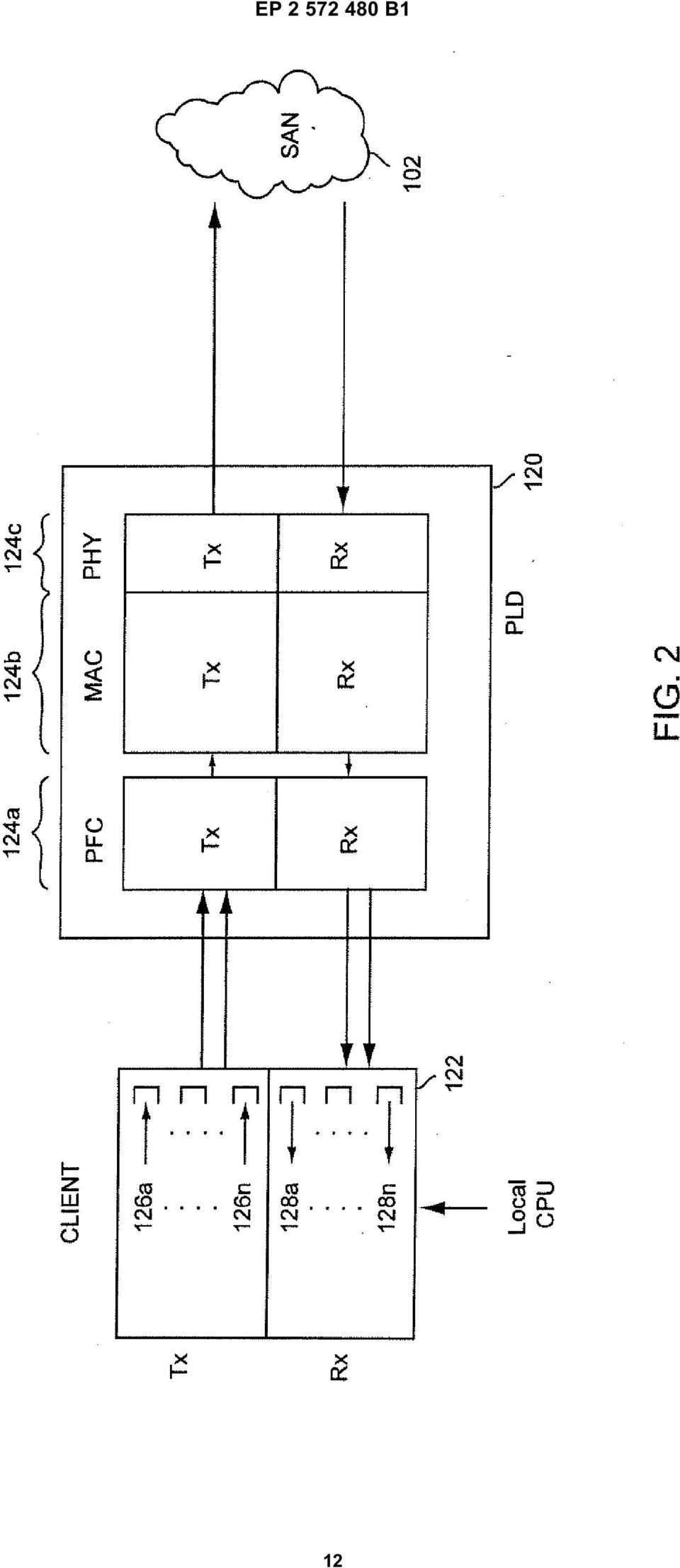
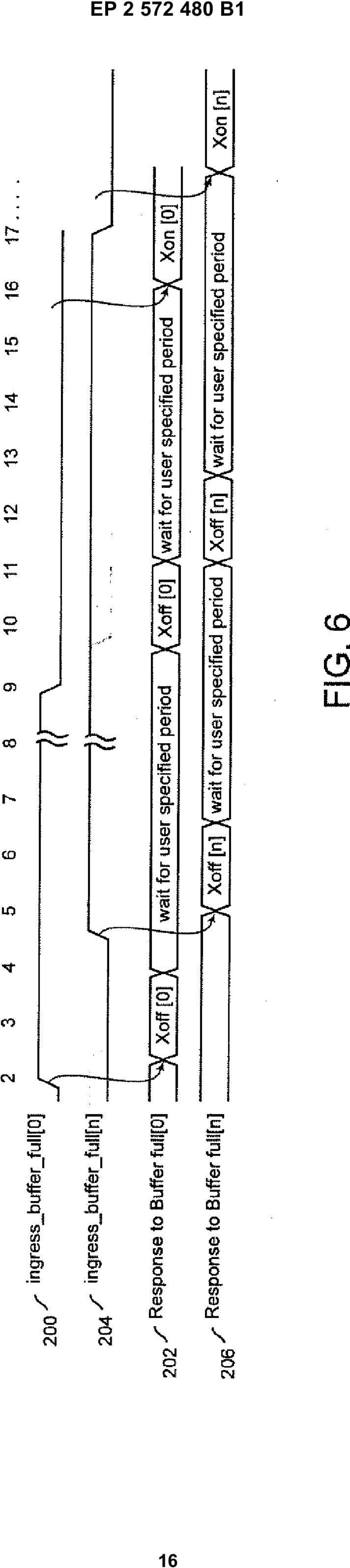
4 EP B1 6 referred to as a quanta. A value of zero in enable vector 6 will essentially disable whatever value is indicated in the corresponding parameter 8. In another embodiment, determination of whether an Xoff or Xon frame is transmitted to the external buffer is based on the corresponding bit values in parameters 8a-n. For example, if the bit value within parameter 8a is a zero, then an Xon frame is sent to the corresponding external buffer. If the bit value is any value besides zero, then an Xoff frame is transmitted to the corresponding external buffer located at the remote end of the network link. In addition, if the bit value is any value besides zero, the bit value represents the amount of pause time, or quanta where one quanta is equal to 12 bit times, prior to rechecking the buffer level. Further details on the packet configuration may be found in IEEE standard 802.1Qbb. [00] Figure 4 is a simplified schematic diagram illustrating the partitioned link control and queue control in accordance with one embodiment. Priority flow control logic 124a includes queue controller logic 180a through 180n. In communication with each instance of queue controller logic 180 is link controller logic 182. It should be appreciated that in one embodiment there is a one to one correspondence between the number of queues, or ingress buffers, in the client and the number of queue controllers 180 in the priority flow control logic, i.e., one queue controller is dedicated to one buffer. For example, if there are eight queues, then there would be eight queue controllers where each queue is associated with a dedicated queue controller. Queue controllers 180a-180n receive a pulse that indicates a corresponding queue or ingress buffer is full. In one embodiment, queue controllers 180an monitor a signal line for a transition. For example, when the signal transitions from a logical low value to a logical high value, this may indicate that the buffer/queue has reached a full limit. It should be noted that the full limit may be a percentage of the full level for the queue in one embodiment. In turn, the corresponding queue controller 180a-n issues a signal, such as a queue status signal to link controller 182 that triggers the link controller to instruct the remote sender to discontinue sending packets to the queue. In one exemplary embodiment, an Xoff signal provides the instruction to discontinue sending packets to the queue. [0016] Still referring to Figure 4, link controller 182 transmits the Xoff signal to the corresponding remote sender and then communicates back to queue controllers 180a-n that link controller 182 is ready for any further action through the link status signal. If the signal monitored by the queue controller transitions from a high value to a low value, the corresponding queue is now available for additional data. Accordingly, the queue status signal will transition to indicate to link controller 182 that an Xon signal may be transmitted to the remote sender in order to continue sending packets. As noted above, the time period (quanta) for waiting before link controller 182 checks the status of the queue status signal is communicated to the link controller through corresponding queue controller 180. Thus, the time period (quanta) for each queue/buffer can be customized through the embodiments described herein so that a non blocking lossless Ethernet connection that does not block any other queue Xoff request is achieved. Thus while link controller 182 is waiting for the time period (quanta) to check the status of a first queue, the link controller is able to check the status of the remaining queues and transmit applicable Xon and Xoff signals for each of the remaining queues as required. In addition, the embodiments eliminate the possibility of buffer overruns as discussed in more detail with reference to Figure 6. [0017] Figure is a simplified schematic diagram illustrating a state diagram for the exchange of status information between the link controller and the queue controllers in accordance with one embodiment. The state diagram for queue controller 180 indicates that the queue controller initially sits idle until a buffer full signal is received. As mentioned above, the buffer full signal may be triggered when the buffer level obtains a percentage of a completely full level. In response to the buffer full signal, an Xoff state occurs and indicates to the link controller that the ingress buffer is full. Upon completion of the transmission of the Xoff signal, link controller 182 communicates the completion of the transmission to queue controller 180 and a wait period occurs for the link controller prior to rechecking the status of the queue controller signal for the queue experiencing the buffer full condition. Once the buffer not full condition is detected an Xon state occurs and link controller 182 transmits an Xon frame. If the buffer congestion still continues, then the state transitions back to the XOFF state. With regard to the state diagram for link controller 182, the link controller is idle until an Xoff or Xon condition is detected through the link_xoff_xon_valid and link_pquanta values. The link_xoff_xon_valid signal indicates that the ingress buffers require either an Xoff or Xon frame to be sent by the link controller in one embodiment. The type of frame may be indicated through a non zero pause quanta value as discussed above. The link_pquanta signal indicates the pause quanta requested by the client in one embodiment. Link controller 182 transmits the corresponding priority flow control frame (Xon or Xoff) to the corresponding remote issuer and returns to an idle state. The link_ready signal indicates that the link controller has sent the corresponding priority flow control frame (Xon or Xoff) and is going to scan the current status information from the queue controller or queue controllers. [0018] Figure 6 is a waveform diagram illustrating the non-blocking flow control between queues in accordance with one embodiment. As illustrated by waveform pairs 200/202 and 204/206, the dedicated queue controllers are able to service their dedicated queues with consistent timing and enable the Xoff frames to be transmitted by the link controller without any blocking. In addition, through the embodiments described herein the specified wait period may be customized for each buffer. The ingress_buffer_full signal of waveform 200 transition to 4

5 7 EP B1 8 a high level and triggers the Xoff[0] transmission depicted in waveform 202. During the wait/pause period after Xoff[0], ingress_buffer_full signal of waveform 204 transitions to a high level. In response, transmission of Xoff[n] is triggered as depicted in waveform 206. Continuing with waveform 202, upon expiration of the first wait period, the level of ingress_buffer_full signal of waveform 200 is sampled and as the level remains at a logical high level, an Xoff transmission results followed by a second wait period. Upon expiration of the second wait period on waveform 202, waveform 200 has transitioned to a logical low value and Xon[0] is transmitted to indicate that buffer 0 can continue to receive data. In a similar manner, upon expiration of the first wait period in waveform 206, the level of ingress_buffer_full signal of waveform 204 is sampled and as the level remains at a logical high level, an Xoff transmission results followed by a second wait period as illustrated on waveform 206. Upon expiration of the second wait period on waveform 206, waveform 204 has transitioned to a logical low value and Xon[n] is transmitted to indicate that buffer n can continue to receive data. It should be appreciated that the embodiments described herein eliminate the possibility of a buffer overrun as a time period from transmission of the signal indicating the buffer full level to detection of the buffer full level is consistent for each dedicated buffer since the queue controllers independently control a response to the signal indicating the buffer full level. It should be further appreciated that under a single controller architecture it is possible to block new Xoff requests for a period of time defined by the wait period and during that wait period, one of the buffers may overflow resulting in a loss of data. The decoupling of the link and queue controller functionality ensures a non-blocking, e.g., lossless environment, which cannot be ensured through a single unified controller architecture. While the exemplary embodiments discuss the link controller as maintaining the pause, it should be appreciated that each queue controller may incorporate the functionality to manage or maintain their respective pauses in an alternative embodiment. [0019] Figure 7 is a simplified flowchart diagram for a finite state machine implementing the method for priority based flow control in accordance with one embodiment. The ingress buffers are scanned for a full condition in operation 20. It should be appreciated that the corresponding queue controller for each ingress buffer may perform the scanning for a full condition in the corresponding buffer. In operation 22, Xoff/Xon signals are transmitted for buffers, with the buffer full flag/not full flag, respectively. As illustrated with reference to Figure 6, transition from between logical values on an ingress_buffer_full signal line may represent a transition from a buffer full condition (buffer full flag) to a buffer not full condition (buffer not full flag). In operation 24, the timers are turned on for the corresponding paused buffers when the buffer full flag is asserted, thereby pausing data being sent to the buffer. If the buffer not full flag is asserted in operation 22, then operation 24 is bypassed and the method returns to operation 20 and repeats as described above. [0020] Embodiments described above may be practiced with various computer system configurations including hand-held devices, microprocessor systems, microprocessor-based or programmable consumer electronics, minicomputers, mainframe computers and the like. The embodiments can also be practiced in distributed computing environments where tasks are performed by remote processing devices that are linked through a wire-based or wireless network. [0021] The embodiments, thus far, were described with respect to integrated circuits. The method and apparatus described herein may be incorporated into any suitable circuit. For example, the method and apparatus may be incorporated into numerous types of devices such as microprocessors or programmable logic devices. Exemplary programmable logic devices include programmable array logic (PAL), programmable logic arrays (PLAs), field programmable logic arrays (FPLAs), electrically programmable logic devices (EPLDs), electrically erasable programmable logic devices (EEPLDs), logic cell arrays (LCAs), field programmable gate arrays (FP- GAs), application specific standard products (ASSPs), application specific integrated circuits (ASICs), just to name a few. [0022] The programmable logic device described herein may be part of a data processing system that includes one or more of the following components; a processor; memory; I/O circuitry; and peripheral devices. The data processing system can be used in a wide variety of applications, such as computer networking, data networking, instrumentation, video processing, digital signal processing, or any suitable other application where the advantage of using programmable or re-programmable logic is desirable. The programmable logic device can be used to perform a variety of different logic functions. For example, the programmable logic device can be configured as a processor or controller that works in cooperation with a system processor. The programmable logic device may also be used as an arbiter for arbitrating access to a shared resource in the data processing system. In yet another example, the programmable logic device can be configured as an interface between a processor and one of the other components in the system. In one embodiment, the programmable logic device may be one of the family of devices owned by the assignee. [0023] Although the method operations were described in a specific order, it should be understood that other operations may be performed in between described operations, described operations may be adjusted so that they occur at slightly different times or described operations may be distributed in a system which allows the occurrence of the processing operations at various intervals associated with the processing, as long as the processing of the overlay operations are performed in a desired way.

6 9 EP B1 [0024] Although the foregoing embodiments have been described in some detail for purposes of clarity of understanding, it will be apparent that certain changes and modifications can be practiced within the scope of the appended claims. Accordingly, the present embodiments are to be considered as illustrative and not restrictive, and the invention is not to be limited to the details given herein, but may be modified within the scope and equivalents of the appended claims. [002] With the above embodiments in mind, it should be understood that the invention can employ various computer-implemented operations involving data stored in computer systems. These operations are those requiring physical manipulation of physical quantities. Usually, though not necessarily, these quantities take the form of electrical or magnetic signals capable of being stored, transferred, combined, compared and otherwise manipulated. [0026] Any of the operations described herein that form part of the invention are useful machine operations. The embodiments also relate to a device or an apparatus for performing these operations. The apparatus can be specially constructed for the required purpose, or the apparatus can be a general-purpose computer selectively activated or configured by a computer program stored in the computer. In particular, various general-purpose machines can be used with computer programs written in accordance with the teachings herein, or it may be more convenient to construct a more specialized apparatus to perform the required operations. [0027] The embodiments can also be embodied as computer readable code on a computer readable medium. The computer readable medium is any data storage device that can store data, which can be thereafter be read by a computer system. Examples of the computer readable medium include hard drives, network attached storage (NAS), read-only memory, random-access memory, CD-ROMs, CD-Rs, CD-RWs, magnetic tapes and other optical and non-optical data storage devices. The computer readable medium can also be distributed over a network-coupled computer system so that the computer readable code is stored and executed in a distributed fashion. [0028] Although the foregoing embodiments have been described in some detail for purposes of clarity of understanding, it will be apparent that certain changes and modifications can be practiced within the scope of the appended claims. Accordingly, the present embodiments are to be considered as illustrative and not restrictive, and the invention is not to be limited to the details given herein, but may be modified within the scope and equivalents of the appended exemplary claims a plurality of queue controllers (180a,..., 180n) in communication with the link controller (182), each of the plurality of queue controllers (180a,..., 180n) operable to be coupled to a corresponding external dedicated buffer (126a,..., 126n; 128a,..., 128n), wherein each external dedicated buffer resides in a remote transmitter (122) that is external to the integrated circuit (120), each of the plurality of queue controllers (180a,..., 180n) operable to monitor and detect a buffer full level for its corresponding external dedicated buffer (126a,..., 126n; 128a,..., 128n), and transmit a signal indicating the buffer full level associated with its corresponding external dedicated buffer to the link controller (182), and the link controller (182) operable to: receive, from a first queue controller, a signal indicating the buffer full condition associated with an monitored external dedicated buffer monitored by said first queue controller, transmit a priority flow control signal to control the data flow to discontinue sending data to said monitored external dedicated buffer based on the received signal from the first queue controller, indicate to the first queue controller that the priority flow control signal was transmitted to said monitored external dedicated buffer, receive, from the first queue controller, a pause time associated with said monitored external dedicated buffer, the pause time indicating a time period that the link controller waits before rechecking a buffer level of said monitored external dedicated buffer. 2. The integrated circuit (120) according to claim 1, wherein said time period from transmission of the signal indicating the buffer full level associated with its corresponding external dedicated buffer to the link controller (182), to detection of the buffer full level is consistent for each external dedicated buffer. 3. The integrated circuit (120) of claim 1, wherein the priority flow control signal is a data packet including a pause time associated with the external dedicated buffer residing in the corresponding remote transmitter (122). 4. The integrated circuit (120) of claim 3, wherein the pause time is independently programmable for each external dedicated buffer. Claims 1. An integrated circuit (120) comprising; a link controller (182); and. The integrated circuit (120) of claim 1, wherein the integrated circuit is a programmable logic device. 6. The integrated circuit (120) of claim 1, wherein the 6

7 11 EP B1 12 integrated circuit is incorporated into a switch operable to process storage data over a network. 7. A method for non-blocking priority flow control, comprising the steps of: monitoring a plurality of buffer level signals indicating a buffer status for a plurality of buffers (126a,...,126n; 128a,...,128n) processing data, the monitoring performed through dedicated queue controllers (180a,..., 180n), wherein each queue controller of the plurality of queue controllers (180a,..., 180n) is coupled to a corresponding buffer of the plurality of buffers (126a,...,126n; 128a,...,128n), wherein the plurality of buffers reside in a remote transmitter (122) of data that is external to an integrated circuit (120) in which the plurality of queue controllers (180a,..., 180n) reside; detecting a buffer full condition at a first buffer of the plurality of buffers processing data through a first queue controller (180a,..., 180n); transmitting an output signal indicating the buffer full condition of the first buffer of the plurality of buffers processing data to a link controller (182); receiving, at the link controller (182), said output signal indicating the buffer full condition associated with the first buffer, transmitting a priority flow control signal to control the data flow to discontinue sending data to the first queue controller based on the output signal, indicating to the first queue controller that the priority flow control signal was transmitted to the first buffer, pausing monitoring of an output signal of the first queue controller for a time period specified by the first signal; and upon expiration of the time period, continuing the monitoring of the output signal of the first queue controller, wherein contemporaneously during the pausing of the monitoring of the output signal of the first queue controller, a second queue controller is monitored. 8. The method of claim 7, further comprising the steps of: transmitting a second signal to cause another, second buffer of the plurality of buffers processing data to discontinue the processing in response to detecting a buffer full condition at the second buffer of the plurality of buffers processing data through a second queue controller of; and pausing the monitoring of an output signal of the second queue controller for a time period specified by the second signal, wherein transmitting the second signal occurs prior to the time period specified by the first signal. 9. The method of claim 8, wherein the time period specified by the second signal is different than the time period specified by the first signal.. The method of claim 7, further comprising the steps of: transmitting a data packet having a bit setting that causes the first buffer to discontinue the processing, wherein the processing is one of transmitting or receiving data packets, and wherein the plurality of buffers processing data are located off chip from the dedicated queue controllers. 11. The method of claim 7, further comprising: detecting a buffer below full condition upon expiration of the time period; and transmitting a third signal to cause the first buffer to continue the processing. 12. The method of claim 11, wherein the third signal and the first signal are data packets and wherein the third signal differs from the first signal solely by a single bit setting of a common field of the data packets. Patentansprüche 1. Integrierte Schaltung (120), die folgendes umfasst: einen Link-Controller (182) und mehrere Queue-Controller (180a,..., 180n) in Kommunikation mit dem Link-Controller (182), wobei jeder der mehreren Queue-Controller (180a,..., 180n) betriebsfähig ist, an einen entsprechenden externen dedizierten Puffer (126a,..., 126n; 128a,..., 128n) gekoppelt zu werden, wobei sich jeder externe dedizierte Puffer in einem entfernten Sender (122) befindet, der sich außerhalb der integrierten Schaltung (120) befindet, wobei jeder der mehreren Queue-Controller (180a,..., 180n) betriebsfähig ist, einen Puffer- Voll-Pegel für seinen entsprechenden externen dedizierten Puffer (126a,..., 126n; 128a,..., 128n) zu überwachen und detektieren, und ein Signal, das den mit seinem entsprechenden externen dedizierten Puffer assoziierten Puffer- Voll-Pegel anzeigt, an den Link-Controller (182) zu übertragen, und wobei der Link-Controller (182) betriebsfähig ist zum: 7
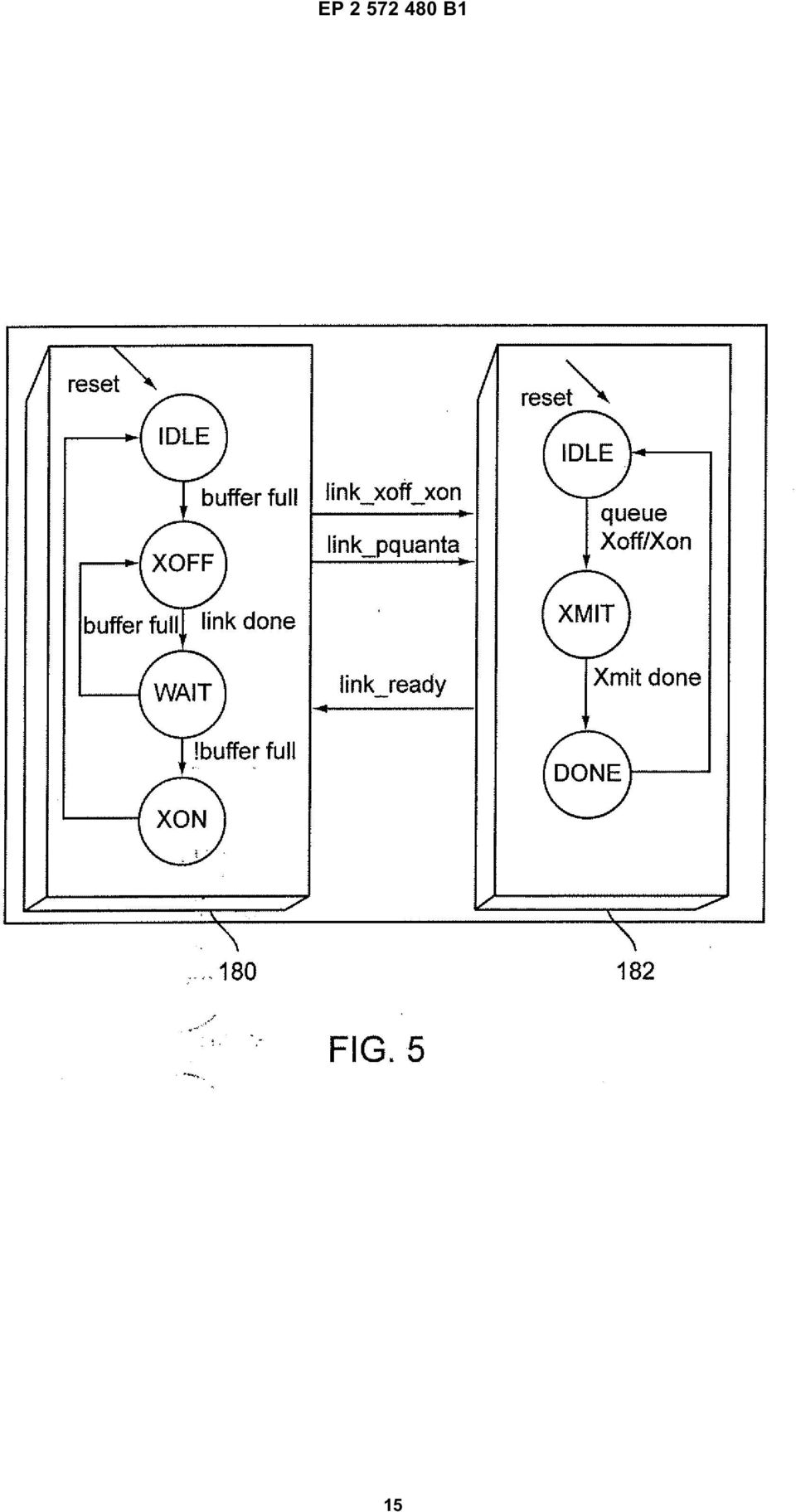
, wherein the plurality of buffers reside in a remote transmitter (122) of data that is external to an integrated circuit (120) in which the plurality of queue controllers (180a,.")
8 13 EP B1 14 Empfangen eines Signals von einem ersten Queue-Controller, das den Puffer-Voll-Zustand anzeigt, der mit einem überwachten externen dedizierten Puffer assoziiert ist, der von dem ersten Queue-Controller überwacht wird, Übertragen eines Prioritätsstrom-Steuersignals zum Steuern des Datenstroms, um das Senden von Daten an den überwachten externen dedizierten Puffer auf der Basis des empfangenen Signals von dem ersten Queue-Controller abzubrechen., dem ersten Queue-Controller anzeigen, dass das Prioritätsstrom-Steuersignal an den überwachten externen dedizierten Puffer übertragen wurde, Empfangen einer mit dem überwachten externen dedizierten Puffer assoziierten Pausezeit von dem ersten Queue-Controller, wobei die Pausezeit eine Zeitperiode anzeigt, während der der Link-Controller wartet, bevor er einen Pufferpegel des überwachten externen dedizierten Puffers erneut prüft. 2. Integrierte Schaltung (120) nach Anspruch 1, wobei die Zeitperiode von der Übertragung des Signals, das den mit seinem entsprechenden externen dedizierten Puffer assoziierten Puffer-Voll-Pegel anzeigt, an den Link-Controller (182), bis zur Detektion des Puffer-Voll-Zustands für jeden externen dedizierten Puffer konsistent ist. 3. Integrierte Schaltung (120) nach Anspruch 1, wobei das Prioritätsstrom-Steuersignal ein Datenpaket ist, das eine Pausenzeit enthält, die mit dem externen dedizierten Puffer assoziiert ist, der in dem entsprechenden entfernten Sender (122) befindet. 4. Integrierte Schaltung (120) nach Anspruch 3, wobei die Pausenzeit für jeden externen dedizierten Puffer unabhängig programmiert werden kann.. Integrierte Schaltung (120) nach Anspruch 1, wobei die integrierte Schaltung ein programmierbares Logikbauelement ist. 6. Integrierte Schaltung (120) nach Anspruch 1, wobei die integrierte Schaltung in einen Schalter integriert ist, der betätigt werden kann, um Speicherdaten über ein Netzwerk zu verarbeiten. 7. Verfahren für eine entsperrende Prioritätsflusssteuerung, das die folgenden Schritte umfasst: Überwachen mehrerer Pufferpegelsignale, die einen Pufferstatus anzeigen, für mehrere Puffer (126a,..., 126n; 128a,..., 128n), die Daten verarbeiten, wobei das Überwachen durch dedizierte Queue-Controller (180a,..., 180n) durchgeführt wird, wobei jeder Queue-Controller (180a,..., 180n) der mehreren Queue-Controller (180a,..., 180n) mit einem entsprechenden Puffer der mehreren Puffer (126a,..., 126n; 128a,..., 128n) gekoppelt ist, wobei sich die mehreren Puffer in einem entfernten Sender (122) von Daten befinden, der sich außerhalb einer integrierten Schaltung (120) befindet, in der sich die mehreren Queue-Controller (180a,..., 180n) befinden; Detektieren eines Puffer-Voll-Zustands eines ersten Puffers der mehreren Daten verarbeitenden Puffer durch einen ersten Queue-Controller (180a,..., 180n); Übertragen eines Ausgangssignals, das den Puffer-Voll-Zustand des ersten Puffers der mehreren Daten verarbeitenden Puffer anzeigt, an einen Link-Controller (182); Empfangen des Ausgangssignals, das den mit dem ersten Puffer assoziierten Puffer-Voll-Zustand anzeigt, an dem Link-Controller (182), Übertragen eines Prioritätsstrom-Steuersignals zum Steuern des Datenstroms, um das Senden von Daten an den ersten Queue-Controller auf der Basis des Ausgangssignals abzubrechen, dem ersten Queue-Controller anzeigen, dass das Prioritätsstrom-Steuersignal an dem ersten Puffer übertragen wurde, Pausieren des Überwachens eines Ausgangssignals des ersten Queue-Controllers für eine durch das erste Signal spezifizierte Zeitperiode und nach Ablauf der Zeitperiode, Fortsetzen des Überwachens des Ausgangssignals des ersten Queue-Controllers, wobei während des Pausierens des Überwachens des Ausgangssignals des ersten Queue-Controllers gleichzeitig ein zweiter Queue-Controller überwacht wird. 8. Verfahren nach Anspruch 7, das weiterhin die folgenden Schritte umfasst: Übertragen eines zweiten Signals, um zu bewirken, dass ein anderer, zweiter Puffer der mehreren Daten verarbeitenden Puffer das Verarbeiten als Reaktion auf das Detektieren eines Puffer-Voll-Zustands beim zweiten Puffer der mehreren Daten verarbeitenden Puffer durch einen zweiten Queue-Controller einstellt; und Pausieren des Überwachens eines Ausgangssignals des zweiten Queue-Controllers für eine durch das zweite Signal spezifizierte Zeitperiode, wobei das Übertragen des zweiten Signals vor der durch das erste Signal spezifizierten Zeitperiode erfolgt. 8

9 EP B Verfahren nach Anspruch 8, wobei die durch das zweite Signal spezifizierte Zeitperiode von der durch das erste Signal spezifizierten Zeitperiode verschieden ist.. Verfahren nach Anspruch 7, das weiterhin die folgenden Schritte umfasst: Übertragen eines Datenpakets mit einer Biteinstellung, die bewirkt, dass der erste Puffer das Verarbeiten einstellt, wobei das Verarbeiten das Übertragen oder Empfangen von Datenpaketen ist und wobei sich die mehreren Daten verarbeitenden Puffer außerhalb eines Chips von den dedizierten Queue-Controllern befinden. 11. Verfahren nach Anspruch 7, das weiterhin Folgendes umfasst: Detektieren eines Puffer-unterhalb-desVoll-Zustands nach Ablauf der Zeitperiode; und Übertragen eines dritten Signals, um zu bewirken, dass der erste Puffer das Verarbeiten fortsetzt. 12. Verfahren nach Anspruch 11, wobei das dritte Signal und das erste Signal Datenpakete sind und wobei sich das dritte Signal ausschließlich durch eine einzelne Biteinstellung eines gemeinsamen Felds der Datenpakete von dem ersten Signal unterscheidet. Revendications 1. Circuit intégré (120), comprenant : un contrôleur de liaison (182) ; et une pluralité de contrôleurs de file d attente (180a,..., 180n) en communication avec le contrôleur de liaison (182) ; chaque contrôleur de la pluralité de contrôleurs de file d attente (180a,..., 180n) étant exploitable de manière à être couplé à une mémoire tampon dédiée externe correspondante (126a,..., 126n ; 128a,..., 128n), dans lequel chaque mémoire tampon dédiée externe réside dans un émetteur distant (122) qui est externe au circuit intégré (120) ; chaque contrôleur de la pluralité de contrôleurs de file d attente (180a,..., 180n) étant exploitable de manière à : surveiller et détecter un niveau de mémoire tampon pleine pour sa propre mémoire tampon dédiée externe correspondante (126a,...,126n ; 128a,..., 128n) ; et transmettre un signal, indiquant le niveau de mémoire tampon pleine associé à sa mémoire tampon dédiée externe correspondante, au contrôleur de liaison (182) ; et le contrôleur de liaison (182) étant exploitable de manière à : recevoir, à partir d un premier contrôleur de file d attente, un signal indiquant l état de mémoire tampon pleine associé à une mémoire tampon dédiée externe surveillée, laquelle est surveillée par ledit premier contrôleur de file d attente ; transmettre un signal de commande de flux prioritaire destiné à commander au flux de données d interrompre l envoi de données à ladite mémoire tampon dédiée externe surveillée, sur la base du signal reçu à partir du premier contrôleur de file d attente ; indiquer au premier contrôleur de file d attente que le signal de commande de flux prioritaire a été transmis à ladite mémoire tampon dédiée externe surveillée ; recevoir, à partir du premier contrôleur de file d attente, une durée de pause associée à ladite mémoire tampon dédiée externe surveillée, la durée de pause indiquant une période de temps pendant laquelle le contrôleur de liaison attend avant de revérifier un niveau de mémoire tampon de ladite mémoire tampon dédiée externe surveillée. 2. Circuit intégré (120) selon la revendication 1, dans lequel ladite période de temps, depuis la transmission du signal, indiquant le niveau de mémoire tampon pleine associé à sa mémoire tampon dédiée externe correspondante, au contrôleur de liaison (182), jusqu à la détection du niveau de mémoire tampon pleine, est constante pour chaque mémoire tampon dédiée externe. 3. Circuit intégré (120) selon la revendication 1, dans lequel le signal de commande de flux prioritaire est un paquet de données incluant une durée de pause associée à la mémoire tampon dédiée externe résidant dans l émetteur distant correspondant (122). 4. Circuit intégré (120) selon la revendication 3, dans lequel la durée de pause est programmable indépendamment pour chaque mémoire tampon dédiée externe.. Circuit intégré (120) selon la revendication 1, dans lequel le circuit intégré est un dispositif logique programmable. 6. Circuit intégré (120) selon la revendication 1, dans lequel le circuit intégré est intégré dans un commutateur exploitable de manière à traiter des données de stockage sur un réseau. 9

10 17 EP B Procédé de commande de flux à base de priorité non bloquante, comprenant les étapes ci-dessous consistant à : surveiller une pluralité de signaux de niveau de mémoire tampon indiquant un état de mémoire tampon pour une pluralité de mémoires tampons (126a,..., 126n ; 128a,..., 128n) traitant des données, dans lequel la surveillance est mise en oeuvre par des contrôleurs de file d attente dédiés (180a,..., 180n), dans lequel chaque contrôleur de file d attente de la pluralité de contrôleurs de file d attente (180a,..., 180n) est couplé à une mémoire tampon correspondante de la pluralité de mémoires tampons (126a,..., 126n ; 128a,..., 128n), dans lequel la pluralité de mémoires tampons réside dans un émetteur distant (122) de données, lequel est externe à un circuit intégré (120) dans lequel réside la pluralité de contrôleurs de file d attente (180a,..., 180n) ; détecter un état de mémoire tampon pleine au niveau d une première mémoire tampon de la pluralité de mémoires tampons traitant des données, par le biais d un premier contrôleur de file d attente (180a,..., 180n) ; transmettre un signal de sortie, indiquant l état de mémoire tampon pleine de la première mémoire tampon de la pluralité de mémoires tampons traitant des données, à un contrôleur de liaison (182) ; recevoir, au niveau du contrôleur de liaison (182), ledit signal de sortie indiquant l état de mémoire tampon pleine associé à la première mémoire tampon ; transmettre un signal de commande de flux prioritaire destiné à commander au flux de données d interrompre l envoi de données au premier contrôleur de file d attente, sur la base du signal de sortie ; indiquer au premier contrôleur de file d attente que le signal de commande de flux prioritaire a été transmis à la première mémoire tampon ; interrompre momentanément la surveillance d un signal de sortie du premier contrôleur de file d attente pendant une période de temps spécifiée par le premier signal ; et à l expiration de la période de temps, reprendre la surveillance du signal de sortie du premier contrôleur de file d attente, dans lequel, simultanément, au cours de l interruption momentanée de la surveillance du signal de sortie du premier contrôleur de file d attente, un second contrôleur de file d attente est surveillé. 8. Procédé selon la revendication 7, comprenant en outre les étapes ci-dessous consistant à : transmettre un second signal destiné à amener une autre seconde mémoire tampon de la pluralité de mémoires tampons traitant des données à interrompre le traitement en réponse à la détection d un état de mémoire tampon pleine au niveau de la seconde mémoire tampon de la pluralité de mémoires tampons traitant des données, par le biais d un second contrôleur de file d attente ; et interrompre momentanément la surveillance d un signal de sortie du second contrôleur de file d attente pendant une période de temps spécifiée par le second signal, dans lequel la transmission du second signal se produit avant la période de temps spécifiée par le premier signal. 9. Procédé selon la revendication 8, dans lequel la période de temps spécifiée par le second signal est différente de la période de temps spécifiée par le premier signal.. Procédé de la revendication 7, comprenant en outre les étapes ci-dessous consistant à : transmettre un paquet de données présentant un réglage de bit qui amène la première mémoire tampon à interrompre le traitement, dans lequel le traitement correspond à l une parmi une transmission ou une réception de paquets de données, et dans lequel la pluralité de mémoires tampons traitant des données est située hors puce par rapport aux contrôleurs de file d attente dédiés. 11. Procédé selon la revendication 7, consistant en outre à: détecter une mémoire tampon dont l état est inférieur à l état plein suite à l expiration de la période de temps ; et transmettre un troisième signal destiné à amener la première mémoire tampon à poursuivre le traitement. 12. Procédé selon la revendication 11, dans lequel le troisième signal et le premier signal correspondent à des paquets de données, et dans lequel le troisième signal ne diffère du premier signal qu en ce qui concerne un réglage de bit unique d un champ commun des paquets de données.
 traitant des données, dans lequel la surveillance est mise en oeuvre par des contrôleurs de file d attente dédiés (180a,.")
11 EP B1 11

12 EP B1 12
13 EP B1 13

14 EP B1 14

15 EP B1
16 EP B1 16
17 EP B1 17

18 EP B1 REFERENCES CITED IN THE DESCRIPTION This list of references cited by the applicant is for the reader s convenience only. It does not form part of the European patent document. Even though great care has been taken in compiling the references, errors or omissions cannot be excluded and the EPO disclaims all liability in this regard. Patent documents cited in the description US A1 [0003] 18

(51) Int Cl.: H04L 29/06 (2006.01) G06F 9/445 (2006.01) G06F 13/00 (2006.01)
 Int Cl.: H04L 29/06 (2006.01) G06F 9/445 (2006.01) G06F 13/00 (2006.01)") (19) TEPZZ_7486_6B_T (11) EP 1 748 616 B1 (12) EUROPEAN PATENT SPECIFICATION (4) Date of publication and mention of the grant of the patent: 03.09.2014 Bulletin 2014/36 (1) Int Cl.: H04L 29/06 (2006.01)
(19) TEPZZ_7486_6B_T (11) EP 1 748 616 B1 (12) EUROPEAN PATENT SPECIFICATION (4) Date of publication and mention of the grant of the patent: 03.09.2014 Bulletin 2014/36 (1) Int Cl.: H04L 29/06 (2006.01)
TEPZZ_768 7_B_T EP 1 768 371 B1 (19) (11) EP 1 768 371 B1 (12) EUROPEAN PATENT SPECIFICATION. (51) Int Cl.: H04M 19/04 (2006.01)
 (11) EP 1 768 371 B1 (12) EUROPEAN PATENT SPECIFICATION. (51) Int Cl.: H04M 19/04 (2006.01)") (19) TEPZZ_768 7_B_T (11) EP 1 768 371 B1 (12) EUROPEAN PATENT SPECIFICATION (4) Date of publication and mention of the grant of the patent: 1.01.2014 Bulletin 2014/03 (1) Int Cl.: H04M 19/04 (2006.01)
(19) TEPZZ_768 7_B_T (11) EP 1 768 371 B1 (12) EUROPEAN PATENT SPECIFICATION (4) Date of publication and mention of the grant of the patent: 1.01.2014 Bulletin 2014/03 (1) Int Cl.: H04M 19/04 (2006.01)
(51) Int Cl.: G06F 13/38 (2006.01) G06F 1/16 (2006.01)
 Int Cl.: G06F 13/38 (2006.01) G06F 1/16 (2006.01)") (19) TEPZZ 9777B_T (11) EP 2 97 77 B1 (12) EUROPEAN PATENT SPECIFICATION (4) Date of publication and mention of the grant of the patent: 1.07.1 Bulletin 1/29 (1) Int Cl.: G06F 13/38 (06.01) G06F 1/16 (06.01)
(19) TEPZZ 9777B_T (11) EP 2 97 77 B1 (12) EUROPEAN PATENT SPECIFICATION (4) Date of publication and mention of the grant of the patent: 1.07.1 Bulletin 1/29 (1) Int Cl.: G06F 13/38 (06.01) G06F 1/16 (06.01)
*EP001173363B1* EP 1 173 363 B1 (19) (11) EP 1 173 363 B1 (12) EUROPEAN PATENT SPECIFICATION
 (11) EP 1 173 363 B1 (12) EUROPEAN PATENT SPECIFICATION") (19) Europäisches Patentamt European Patent Office Office européen des brevets *EP001173363B1* (11) EP 1 173 363 B1 (12) EUROPEAN PATENT SPECIFICATION (4) Date of publication and mention of the grant of
(19) Europäisches Patentamt European Patent Office Office européen des brevets *EP001173363B1* (11) EP 1 173 363 B1 (12) EUROPEAN PATENT SPECIFICATION (4) Date of publication and mention of the grant of
(51) Int Cl.: G06F 21/00 (2006.01) H04L 29/06 (2006.01)
 Int Cl.: G06F 21/00 (2006.01) H04L 29/06 (2006.01)") (19) TEPZZ_8Z_7 _B_T (11) EP 1 801 721 B1 (12) EUROPEAN PATENT SPECIFICATION (4) Date of publication and mention of the grant of the patent: 16.06. Bulletin /24 (1) Int Cl.: G06F 21/00 (06.01) H04L 29/06
(19) TEPZZ_8Z_7 _B_T (11) EP 1 801 721 B1 (12) EUROPEAN PATENT SPECIFICATION (4) Date of publication and mention of the grant of the patent: 16.06. Bulletin /24 (1) Int Cl.: G06F 21/00 (06.01) H04L 29/06
(51) Int Cl.: B29C 41/20 (2006.01) F21S 4/00 (2006.01) H05K 3/28 (2006.01)
 Int Cl.: B29C 41/20 (2006.01) F21S 4/00 (2006.01) H05K 3/28 (2006.01)") (19) TEPZZ 68698B_T (11) EP 2 68 698 B1 (12) EUROPEAN PATENT SPECIFICATION (4) Date of publication and mention of the grant of the patent: 18.11.201 Bulletin 201/47 (21) Application number: 11808612.3
(19) TEPZZ 68698B_T (11) EP 2 68 698 B1 (12) EUROPEAN PATENT SPECIFICATION (4) Date of publication and mention of the grant of the patent: 18.11.201 Bulletin 201/47 (21) Application number: 11808612.3
(51) Int Cl.: H04W 4/14 (2009.01)
 Int Cl.: H04W 4/14 (2009.01)") (19) (12) EUROPEAN PATENT SPECIFICATION (11) EP 2 184 897 B1 (4) Date of publication and mention of the grant of the patent: 14.03.12 Bulletin 12/11 (21) Application number: 087774.3 (22) Date of filing:
(19) (12) EUROPEAN PATENT SPECIFICATION (11) EP 2 184 897 B1 (4) Date of publication and mention of the grant of the patent: 14.03.12 Bulletin 12/11 (21) Application number: 087774.3 (22) Date of filing:
(51) Int Cl.: G06F 9/455 (2006.01) G06F 9/50 (2006.01)
 Int Cl.: G06F 9/455 (2006.01) G06F 9/50 (2006.01)") (19) TEPZZ 6987 B_T (11) EP 2 698 711 B1 (12) EUROPEAN PATENT SPECIFICATION (4) Date of publication and mention of the grant of the patent: 0.08.1 Bulletin 1/32 (21) Application number: 118777.8 (22) Date
(19) TEPZZ 6987 B_T (11) EP 2 698 711 B1 (12) EUROPEAN PATENT SPECIFICATION (4) Date of publication and mention of the grant of the patent: 0.08.1 Bulletin 1/32 (21) Application number: 118777.8 (22) Date
TEPZZ 5Z _9_B_T EP 2 502 191 B1 (19) (11) EP 2 502 191 B1 (12) EUROPEAN PATENT SPECIFICATION
 (11) EP 2 502 191 B1 (12) EUROPEAN PATENT SPECIFICATION") (19) TEPZZ Z _9_B_T (11) EP 2 02 191 B1 (12) EUROPEAN PATENT SPECIFICATION (4) Date of publication and mention of the grant of the patent: 17.06.1 Bulletin 1/2 (21) Application number: 787872.0 (22) Date
(19) TEPZZ Z _9_B_T (11) EP 2 02 191 B1 (12) EUROPEAN PATENT SPECIFICATION (4) Date of publication and mention of the grant of the patent: 17.06.1 Bulletin 1/2 (21) Application number: 787872.0 (22) Date
TEPZZ 87_546A T EP 2 871 546 A2 (19) (11) EP 2 871 546 A2 (12) EUROPEAN PATENT APPLICATION. (51) Int Cl.: G05B 19/05 (2006.01)
 (11) EP 2 871 546 A2 (12) EUROPEAN PATENT APPLICATION. (51) Int Cl.: G05B 19/05 (2006.01)") (19) TEPZZ 87_46A T (11) EP 2 871 46 A2 (12) EUROPEAN PATENT APPLICATION (43) Date of publication: 13.0.1 Bulletin 1/ (1) Int Cl.: G0B 19/0 (06.01) (21) Application number: 14188238.1 (22) Date of filing:
(19) TEPZZ 87_46A T (11) EP 2 871 46 A2 (12) EUROPEAN PATENT APPLICATION (43) Date of publication: 13.0.1 Bulletin 1/ (1) Int Cl.: G0B 19/0 (06.01) (21) Application number: 14188238.1 (22) Date of filing:
(51) Int Cl.: H04L 12/56 (2006.01)
 Int Cl.: H04L 12/56 (2006.01)") (19) (11) EP 1 779 90 B1 (12) EUROPEAN PATENT SPECIFICATION (4) Date of publication and mention of the grant of the patent: 28.12.11 Bulletin 11/2 (21) Application number: 0783482.2 (22) Date of filing:
(19) (11) EP 1 779 90 B1 (12) EUROPEAN PATENT SPECIFICATION (4) Date of publication and mention of the grant of the patent: 28.12.11 Bulletin 11/2 (21) Application number: 0783482.2 (22) Date of filing:
(51) Int Cl.: H04L 12/58 (2006.01)
 Int Cl.: H04L 12/58 (2006.01)") (19) (11) EP 1 628 448 B1 (12) EUROPEAN PATENT SPECIFICATION (4) Date of publication and mention of the grant of the patent: 21.11.07 Bulletin 07/47 (1) Int Cl.: H04L 12/8 (06.01) (21) Application number:
(19) (11) EP 1 628 448 B1 (12) EUROPEAN PATENT SPECIFICATION (4) Date of publication and mention of the grant of the patent: 21.11.07 Bulletin 07/47 (1) Int Cl.: H04L 12/8 (06.01) (21) Application number:
(51) Int Cl.: G05F 3/26 (2006.01) G05F 3/24 (2006.01)
 Int Cl.: G05F 3/26 (2006.01) G05F 3/24 (2006.01)") (19) Europäisches Patentamt European Patent Office Office européen des brevets (11) EP 1 280 033 B1 (12) EUROPEAN PATENT SPECIFICATION (4) Date of publication and mention of the grant of the patent: 31.0.2006
(19) Europäisches Patentamt European Patent Office Office européen des brevets (11) EP 1 280 033 B1 (12) EUROPEAN PATENT SPECIFICATION (4) Date of publication and mention of the grant of the patent: 31.0.2006
(51) Int Cl.: H04N 7/16 (2011.01)
 Int Cl.: H04N 7/16 (2011.01)") (19) TEPZZ_796 89B_T (11) EP 1 796 389 B1 (12) EUROPEAN PATENT SPECIFICATION (4) Date of publication and mention of the grant of the patent: 04.03.1 Bulletin 1/ (1) Int Cl.: H04N 7/16 (11.01) (21) Application
(19) TEPZZ_796 89B_T (11) EP 1 796 389 B1 (12) EUROPEAN PATENT SPECIFICATION (4) Date of publication and mention of the grant of the patent: 04.03.1 Bulletin 1/ (1) Int Cl.: H04N 7/16 (11.01) (21) Application
TEPZZ 9 Z5A_T EP 2 922 305 A1 (19) (11) EP 2 922 305 A1. (12) EUROPEAN PATENT APPLICATION published in accordance with Art.
 (11) EP 2 922 305 A1. (12) EUROPEAN PATENT APPLICATION published in accordance with Art.") (19) TEPZZ 9 ZA_T (11) EP 2 922 A1 (12) EUROPEAN PATENT APPLICATION published in accordance with Art. 13(4) EPC (43) Date of publication: 23.09.1 Bulletin 1/39 (21) Application number: 1386446.2 (22) Date
(19) TEPZZ 9 ZA_T (11) EP 2 922 A1 (12) EUROPEAN PATENT APPLICATION published in accordance with Art. 13(4) EPC (43) Date of publication: 23.09.1 Bulletin 1/39 (21) Application number: 1386446.2 (22) Date
TEPZZ 68575_A_T EP 2 685 751 A1 (19) (11) EP 2 685 751 A1. (12) EUROPEAN PATENT APPLICATION published in accordance with Art.
 (11) EP 2 685 751 A1. (12) EUROPEAN PATENT APPLICATION published in accordance with Art.") (19) TEPZZ 687_A_T (11) EP 2 68 71 A1 (12) EUROPEAN PATENT APPLICATION published in accordance with Art. 3(4) EPC (43) Date of publication:.01.14 Bulletin 14/03 (21) Application number: 1278849.6 (22)
(19) TEPZZ 687_A_T (11) EP 2 68 71 A1 (12) EUROPEAN PATENT APPLICATION published in accordance with Art. 3(4) EPC (43) Date of publication:.01.14 Bulletin 14/03 (21) Application number: 1278849.6 (22)
(51) Int Cl.: H04L 29/06 (2006.01) H04M 15/00 (2006.01)
 Int Cl.: H04L 29/06 (2006.01) H04M 15/00 (2006.01)") (19) TEPZZ 7Z 74 B_T (11) EP 2 702 742 B1 (12) EUROPEAN PATENT SPECIFICATION (4) Date of publication and mention of the grant of the patent:.04. Bulletin /16 (21) Application number: 1171674.6 (22) Date
(19) TEPZZ 7Z 74 B_T (11) EP 2 702 742 B1 (12) EUROPEAN PATENT SPECIFICATION (4) Date of publication and mention of the grant of the patent:.04. Bulletin /16 (21) Application number: 1171674.6 (22) Date
(51) Int Cl.: G10L 15/26 (2006.01)
 Int Cl.: G10L 15/26 (2006.01)") (19) TEPZZ Z 8B_T (11) EP 2 023 338 B1 (12) EUROPEAN PATENT SPECIFICATION (4) Date of publication and mention of the grant of the patent: 28.0.14 Bulletin 14/22 (1) Int Cl.: GL /26 (06.01) (21) Application
(19) TEPZZ Z 8B_T (11) EP 2 023 338 B1 (12) EUROPEAN PATENT SPECIFICATION (4) Date of publication and mention of the grant of the patent: 28.0.14 Bulletin 14/22 (1) Int Cl.: GL /26 (06.01) (21) Application
EP 2 455 926 A1 (19) (11) EP 2 455 926 A1 (12) EUROPEAN PATENT APPLICATION. (43) Date of publication: 23.05.2012 Bulletin 2012/21
 (11) EP 2 455 926 A1 (12) EUROPEAN PATENT APPLICATION. (43) Date of publication: 23.05.2012 Bulletin 2012/21") (19) (12) EUROPEAN PATENT APPLICATION (11) EP 2 4 926 A1 (43) Date of publication: 23.0.2012 Bulletin 2012/21 (21) Application number: 11190024.7 (1) Int Cl.: G08B 2/14 (2006.01) G08B 2/00 (2006.01) G0B
(19) (12) EUROPEAN PATENT APPLICATION (11) EP 2 4 926 A1 (43) Date of publication: 23.0.2012 Bulletin 2012/21 (21) Application number: 11190024.7 (1) Int Cl.: G08B 2/14 (2006.01) G08B 2/00 (2006.01) G0B
(51) Int Cl.: H04M 3/42 (2006.01) H04Q 3/00 (2006.01)
 Int Cl.: H04M 3/42 (2006.01) H04Q 3/00 (2006.01)") (19) (11) EP 1 696 646 B1 (12) EUROPEAN PATENT SPECIFICATION (4) Date of publication and mention of the grant of the patent: 07.03.12 Bulletin 12/ (1) Int Cl.: H04M 3/42 (06.01) H04Q 3/00 (06.01) (21)
(19) (11) EP 1 696 646 B1 (12) EUROPEAN PATENT SPECIFICATION (4) Date of publication and mention of the grant of the patent: 07.03.12 Bulletin 12/ (1) Int Cl.: H04M 3/42 (06.01) H04Q 3/00 (06.01) (21)
(51) Int Cl.: H04L 12/26 (2006.01)
 Int Cl.: H04L 12/26 (2006.01)") (19) TEPZZ 84 8B_T (11) EP 2 84 338 B1 (12) EUROPEAN PATENT SPECIFICATION (4) Date of publication and mention of the grant of the patent: 23.09.1 Bulletin 1/39 (1) Int Cl.: H04L 12/26 (06.01) (21) Application
(19) TEPZZ 84 8B_T (11) EP 2 84 338 B1 (12) EUROPEAN PATENT SPECIFICATION (4) Date of publication and mention of the grant of the patent: 23.09.1 Bulletin 1/39 (1) Int Cl.: H04L 12/26 (06.01) (21) Application
(51) Int Cl.: G06F 1/00 (2006.01)
 Int Cl.: G06F 1/00 (2006.01)") (19) (11) EP 0 972 234 B1 (12) EUROPEAN PATENT SPECIFICATION (4) Date of publication and mention of the grant of the patent: 0.09.07 Bulletin 07/36 (21) Application number: 98913219.6 (22) Date of filing:
(19) (11) EP 0 972 234 B1 (12) EUROPEAN PATENT SPECIFICATION (4) Date of publication and mention of the grant of the patent: 0.09.07 Bulletin 07/36 (21) Application number: 98913219.6 (22) Date of filing:
The Advantialer and Its Advantages
 (19) TEPZZ Z B_T (11) EP 2 0 113 B1 (12) EUROPEAN PATENT SPECIFICATION (4) Date of publication and mention of the grant of the patent: 16.09.1 Bulletin 1/38 (21) Application number: 07809477.8 (22) Date
(51) Int Cl.: H04L 29/08 (2006.01) H04L 29/06 (2006.01)
 Int Cl.: H04L 29/08 (2006.01) H04L 29/06 (2006.01)") (19) TEPZZ_897 6B_T (11) EP 1 897 336 B1 (12) EUROPEAN PATENT SPECIFICATION (4) Date of publication and mention of the grant of the patent: 12.08.1 Bulletin 1/33 (21) Application number: 06779738.1 (22)
(19) TEPZZ_897 6B_T (11) EP 1 897 336 B1 (12) EUROPEAN PATENT SPECIFICATION (4) Date of publication and mention of the grant of the patent: 12.08.1 Bulletin 1/33 (21) Application number: 06779738.1 (22)
TEPZZ 94Z968A_T EP 2 940 968 A1 (19) (11) EP 2 940 968 A1 (12) EUROPEAN PATENT APPLICATION. (51) Int Cl.: H04L 29/08 (2006.01)
 (11) EP 2 940 968 A1 (12) EUROPEAN PATENT APPLICATION. (51) Int Cl.: H04L 29/08 (2006.01)") (19) TEPZZ 94Z968A_T (11) EP 2 940 968 A1 (12) EUROPEAN PATENT APPLICATION (43) Date of publication: 04.11.20 Bulletin 20/4 (1) Int Cl.: H04L 29/08 (2006.01) (21) Application number: 1430649.7 (22) Date
(19) TEPZZ 94Z968A_T (11) EP 2 940 968 A1 (12) EUROPEAN PATENT APPLICATION (43) Date of publication: 04.11.20 Bulletin 20/4 (1) Int Cl.: H04L 29/08 (2006.01) (21) Application number: 1430649.7 (22) Date
(51) Int Cl.: G08B 21/02 (2006.01) H04M 11/04 (2006.01)
 Int Cl.: G08B 21/02 (2006.01) H04M 11/04 (2006.01)") (19) Europäisches Patentamt European Patent Office Office européen des brevets (11) EP 1 224 642 B1 (12) EUROPEAN PATENT SPECIFICATION (4) Date of publication and mention of the grant of the patent: 1.03.06
(19) Europäisches Patentamt European Patent Office Office européen des brevets (11) EP 1 224 642 B1 (12) EUROPEAN PATENT SPECIFICATION (4) Date of publication and mention of the grant of the patent: 1.03.06
(51) Int Cl.: H04L 29/06 (2006.01) (56) References cited:
 Int Cl.: H04L 29/06 (2006.01) (56) References cited:") (19) (11) EP 1 4 48 B1 (12) EUROPEAN PATENT SPECIFICATION (4) Date of publication and mention of the grant of the patent: 06.08.08 Bulletin 08/32 (21) Application number: 02776379.6 (22) Date of filing:..02
(19) (11) EP 1 4 48 B1 (12) EUROPEAN PATENT SPECIFICATION (4) Date of publication and mention of the grant of the patent: 06.08.08 Bulletin 08/32 (21) Application number: 02776379.6 (22) Date of filing:..02
(51) Int Cl.: H04L 12/24 (2006.01)
 Int Cl.: H04L 12/24 (2006.01)") (19) TEPZZ_8_9Z96B_T (11) EP 1 819 096 B1 (12) EUROPEAN PATENT SPECIFICATION (4) Date of publication and mention of the grant of the patent: 24..12 Bulletin 12/43 (21) Application number: 0818628.9 (22)
(19) TEPZZ_8_9Z96B_T (11) EP 1 819 096 B1 (12) EUROPEAN PATENT SPECIFICATION (4) Date of publication and mention of the grant of the patent: 24..12 Bulletin 12/43 (21) Application number: 0818628.9 (22)
(51) Int Cl. 7 : G03G 15/00
 Int Cl. 7 : G03G 15/00") (19) Europäisches Patentamt European Patent Office Office européen des brevets *EP001179B1* (11) EP 1 17 9 B1 (12) EUROPEAN PATENT SPECIFICATION (4) Date of publication and mention of the grant of the
(19) Europäisches Patentamt European Patent Office Office européen des brevets *EP001179B1* (11) EP 1 17 9 B1 (12) EUROPEAN PATENT SPECIFICATION (4) Date of publication and mention of the grant of the
(51) Int Cl. 7 : G06F 11/22
 Int Cl. 7 : G06F 11/22") (19) Europäisches Patentamt European Patent Office Office européen des brevets *EP00084463B1* (11) EP 0 844 63 B1 (12) EUROPEAN PATENT SPECIFICATION (4) Date of publication and mention of the grant of
(19) Europäisches Patentamt European Patent Office Office européen des brevets *EP00084463B1* (11) EP 0 844 63 B1 (12) EUROPEAN PATENT SPECIFICATION (4) Date of publication and mention of the grant of
(51) Int Cl.: H04L 12/56 (2006.01) H04L 12/28 (2006.01) H04M 7/00 (2006.01)
 Int Cl.: H04L 12/56 (2006.01) H04L 12/28 (2006.01) H04M 7/00 (2006.01)") (19) (12) EUROPEAN PATENT SPECIFICATION (11) EP 1 129 0 B1 (4) Date of publication and mention of the grant of the patent: 09.04.08 Bulletin 08/1 (21) Application number: 9996836.2 (22) Date of filing:
(19) (12) EUROPEAN PATENT SPECIFICATION (11) EP 1 129 0 B1 (4) Date of publication and mention of the grant of the patent: 09.04.08 Bulletin 08/1 (21) Application number: 9996836.2 (22) Date of filing:
(51) Int Cl.: H04L 12/24 (2006.01) G06F 9/445 (2006.01)
 Int Cl.: H04L 12/24 (2006.01) G06F 9/445 (2006.01)") (19) (12) EUROPEAN PATENT SPECIFICATION (11) EP 1 978 672 B1 (4) Date of publication and mention of the grant of the patent: 01.09. Bulletin /3 (1) Int Cl.: H04L 12/24 (06.01) G06F 9/44 (06.01) (21) Application
(19) (12) EUROPEAN PATENT SPECIFICATION (11) EP 1 978 672 B1 (4) Date of publication and mention of the grant of the patent: 01.09. Bulletin /3 (1) Int Cl.: H04L 12/24 (06.01) G06F 9/44 (06.01) (21) Application
TEPZZ 6_Z76 A_T EP 2 610 763 A1 (19) (11) EP 2 610 763 A1 (12) EUROPEAN PATENT APPLICATION. (51) Int Cl.:
 (11) EP 2 610 763 A1 (12) EUROPEAN PATENT APPLICATION. (51) Int Cl.:") (19) TEPZZ 6_Z76 A_T (11) EP 2 6 763 A1 (12) EUROPEAN PATENT APPLICATION (43) Date of publication: 03.07.2013 Bulletin 2013/27 (51) Int Cl.: G06F 17/30 (2006.01) (21) Application number: 12192220.7 (22)
(19) TEPZZ 6_Z76 A_T (11) EP 2 6 763 A1 (12) EUROPEAN PATENT APPLICATION (43) Date of publication: 03.07.2013 Bulletin 2013/27 (51) Int Cl.: G06F 17/30 (2006.01) (21) Application number: 12192220.7 (22)
EP 1 976 249 B1 (19) (11) EP 1 976 249 B1 (12) EUROPEAN PATENT SPECIFICATION
 (11) EP 1 976 249 B1 (12) EUROPEAN PATENT SPECIFICATION") (19) (11) EP 1 976 249 B1 (12) EUROPEAN PATENT SPECIFICATION (4) Date of publication and mention of the grant of the patent: 11.03.09 Bulletin 09/11 (1) Int Cl.: H04M 1/72 (06.01) G06F 9/44 (06.01) H04W
(19) (11) EP 1 976 249 B1 (12) EUROPEAN PATENT SPECIFICATION (4) Date of publication and mention of the grant of the patent: 11.03.09 Bulletin 09/11 (1) Int Cl.: H04M 1/72 (06.01) G06F 9/44 (06.01) H04W
(51) Int Cl.: H04L 12/10 (2006.01) H04L 12/40 (2006.01)
 Int Cl.: H04L 12/10 (2006.01) H04L 12/40 (2006.01)") (19) TEPZZ 4799 B_T (11) EP 2 479 92 B1 (12) EUROPEAN PATENT SPECIFICATION (4) Date of publication and mention of the grant of the patent: 14.0.14 Bulletin 14/ (1) Int Cl.: H04L 12/ (06.01) H04L 12/ (06.01)
(19) TEPZZ 4799 B_T (11) EP 2 479 92 B1 (12) EUROPEAN PATENT SPECIFICATION (4) Date of publication and mention of the grant of the patent: 14.0.14 Bulletin 14/ (1) Int Cl.: H04L 12/ (06.01) H04L 12/ (06.01)
(51) Int Cl.: H04M 3/50 (2006.01)
 Int Cl.: H04M 3/50 (2006.01)") (19) TEPZZ_Z48_64B_T (11) EP 1 048 164 B1 (12) EUROPEAN PATENT SPECIFICATION (4) Date of publication and mention of the grant of the patent: 07.01.1 Bulletin 1/02 (21) Application number: 9893133.0 (22)
(19) TEPZZ_Z48_64B_T (11) EP 1 048 164 B1 (12) EUROPEAN PATENT SPECIFICATION (4) Date of publication and mention of the grant of the patent: 07.01.1 Bulletin 1/02 (21) Application number: 9893133.0 (22)
TEPZZ 69 49A_T EP 2 693 349 A1 (19) (11) EP 2 693 349 A1 (12) EUROPEAN PATENT APPLICATION. (51) Int Cl.: G06F 17/30 (2006.01)
 (11) EP 2 693 349 A1 (12) EUROPEAN PATENT APPLICATION. (51) Int Cl.: G06F 17/30 (2006.01)") (19) TEPZZ 69 49A_T (11) EP 2 693 349 A1 (12) EUROPEAN PATENT APPLICATION (43) Date of publication: 0.02.2014 Bulletin 2014/06 (1) Int Cl.: G06F 17/30 (2006.01) (21) Application number: 13160696.4 (22)
(19) TEPZZ 69 49A_T (11) EP 2 693 349 A1 (12) EUROPEAN PATENT APPLICATION (43) Date of publication: 0.02.2014 Bulletin 2014/06 (1) Int Cl.: G06F 17/30 (2006.01) (21) Application number: 13160696.4 (22)
(51) Int Cl.: H04W 8/16 (2009.01) H04L 29/12 (2006.01) H04W 8/18 (2009.01)
 Int Cl.: H04W 8/16 (2009.01) H04L 29/12 (2006.01) H04W 8/18 (2009.01)") (19) TEPZZ 474_77B_T (11) EP 2 474 177 B1 (12) EUROPEAN PATENT SPECIFICATION (4) Date of publication and mention of the grant of the patent: 0.11.14 Bulletin 14/4 (21) Application number: 747648.3 (22)
(19) TEPZZ 474_77B_T (11) EP 2 474 177 B1 (12) EUROPEAN PATENT SPECIFICATION (4) Date of publication and mention of the grant of the patent: 0.11.14 Bulletin 14/4 (21) Application number: 747648.3 (22)
(51) Int Cl.: G08G 1/14 (2006.01) G07B 15/02 (2006.01) G10L 15/28 (2006.01)
 Int Cl.: G08G 1/14 (2006.01) G07B 15/02 (2006.01) G10L 15/28 (2006.01)") (19) (12) EUROPEAN PATENT SPECIFICATION (11) EP 1 862 986 B1 (4) Date of publication and mention of the grant of the patent: 14.07. Bulletin /28 (1) Int Cl.: G08G 1/14 (06.01) G07B 1/02 (06.01) GL 1/28
(19) (12) EUROPEAN PATENT SPECIFICATION (11) EP 1 862 986 B1 (4) Date of publication and mention of the grant of the patent: 14.07. Bulletin /28 (1) Int Cl.: G08G 1/14 (06.01) G07B 1/02 (06.01) GL 1/28
(51) Int Cl.: H04L 29/06 (2006.01) H04Q 7/24 (2006.01) H04L 12/66 (2006.01)
 Int Cl.: H04L 29/06 (2006.01) H04Q 7/24 (2006.01) H04L 12/66 (2006.01)") (19) (11) EP 1 314 291 B1 (12) EUROPEAN PATENT SPECIFICATION (4) Date of publication and mention of the grant of the patent:..07 Bulletin 07/41 (21) Application number: 0194907.2 (22) Date of filing: 06.07.01
(19) (11) EP 1 314 291 B1 (12) EUROPEAN PATENT SPECIFICATION (4) Date of publication and mention of the grant of the patent:..07 Bulletin 07/41 (21) Application number: 0194907.2 (22) Date of filing: 06.07.01
(51) Int Cl.: G06Q 10/00 (2006.01)
 Int Cl.: G06Q 10/00 (2006.01)") (19) (11) EP 1 69 282 B1 (12) EUROPEAN PATENT SPECIFICATION (4) Date of publication and mention of the grant of the patent: 2.03.09 Bulletin 09/13 (21) Application number: 048.1 (22) Date of filing: 29.11.04
(19) (11) EP 1 69 282 B1 (12) EUROPEAN PATENT SPECIFICATION (4) Date of publication and mention of the grant of the patent: 2.03.09 Bulletin 09/13 (21) Application number: 048.1 (22) Date of filing: 29.11.04
(51) Int Cl.: H04B 3/23 (2006.01)
 Int Cl.: H04B 3/23 (2006.01)") (19) (11) EP 0 983 638 B1 (12) EUROPEAN PATENT SPECIFICATION (4) Date of publication and mention of the grant of the patent: 21.03.12 Bulletin 12/12 (21) Application number: 989232.7 (22) Date of filing:
(19) (11) EP 0 983 638 B1 (12) EUROPEAN PATENT SPECIFICATION (4) Date of publication and mention of the grant of the patent: 21.03.12 Bulletin 12/12 (21) Application number: 989232.7 (22) Date of filing:
(51) Int Cl.: C08K 5/523 (2006.01) C08K 5/521 (2006.01) C08K 5/52 (2006.01) C08G 64/00 (2006.01)
 Int Cl.: C08K 5/523 (2006.01) C08K 5/521 (2006.01) C08K 5/52 (2006.01) C08G 64/00 (2006.01)") (19) Europäisches Patentamt European Patent Office Office européen des brevets (11) EP 0 78 966 B1 (12) EUROPEAN PATENT SPECIFICATION (4) Date of publication and mention of the grant of the patent: 01.03.06
(19) Europäisches Patentamt European Patent Office Office européen des brevets (11) EP 0 78 966 B1 (12) EUROPEAN PATENT SPECIFICATION (4) Date of publication and mention of the grant of the patent: 01.03.06
TEPZZ 87657ZA_T EP 2 876 570 A1 (19) (11) EP 2 876 570 A1 (12) EUROPEAN PATENT APPLICATION
 (11) EP 2 876 570 A1 (12) EUROPEAN PATENT APPLICATION") (19) TEPZZ 8767ZA_T (11) EP 2 876 70 A1 (12) EUROPEAN PATENT APPLICATION (43) Date of publication: 27.0.201 Bulletin 201/22 (21) Application number: 14189809.8 (1) Int Cl.: G06F 21/34 (2013.01) G08B 13/196
(19) TEPZZ 8767ZA_T (11) EP 2 876 70 A1 (12) EUROPEAN PATENT APPLICATION (43) Date of publication: 27.0.201 Bulletin 201/22 (21) Application number: 14189809.8 (1) Int Cl.: G06F 21/34 (2013.01) G08B 13/196
(51) Int Cl.: H04L 12/66 (2006.01)
 Int Cl.: H04L 12/66 (2006.01)") (19) (12) EUROPEAN PATENT SPECIFICATION (11) EP 1 73 43 B1 (4) Date of publication and mention of the grant of the patent: 18.01.12 Bulletin 12/03 (21) Application number: 02792. (22) Date of filing: 26.12.02
(19) (12) EUROPEAN PATENT SPECIFICATION (11) EP 1 73 43 B1 (4) Date of publication and mention of the grant of the patent: 18.01.12 Bulletin 12/03 (21) Application number: 02792. (22) Date of filing: 26.12.02
TEPZZ 65Z79 A_T EP 2 650 793 A1 (19) (11) EP 2 650 793 A1. (12) EUROPEAN PATENT APPLICATION published in accordance with Art.
 (11) EP 2 650 793 A1. (12) EUROPEAN PATENT APPLICATION published in accordance with Art.") (19) TEPZZ 65Z79 A_T (11) EP 2 650 793 A1 (12) EUROPEAN PATENT APPLICATION published in accordance with Art. 153(4) EPC (43) Date of publication: 16.10.2013 Bulletin 2013/42 (21) Application number: 12818771.3
(19) TEPZZ 65Z79 A_T (11) EP 2 650 793 A1 (12) EUROPEAN PATENT APPLICATION published in accordance with Art. 153(4) EPC (43) Date of publication: 16.10.2013 Bulletin 2013/42 (21) Application number: 12818771.3
(51) Int Cl.: H04L 12/24 (2006.01)
 Int Cl.: H04L 12/24 (2006.01)") (19) (12) EUROPEAN PATENT SPECIFICATION (11) EP 1 487 11 B1 (4) Date of publication and mention of the grant of the patent: 01.07.09 Bulletin 09/27 (1) Int Cl.: H04L 12/24 (06.01) (21) Application number:
(19) (12) EUROPEAN PATENT SPECIFICATION (11) EP 1 487 11 B1 (4) Date of publication and mention of the grant of the patent: 01.07.09 Bulletin 09/27 (1) Int Cl.: H04L 12/24 (06.01) (21) Application number:
(51) Int Cl.: H05K 1/02 (2006.01)
 Int Cl.: H05K 1/02 (2006.01)") (19) TEPZZ 4 67B_T (11) EP 2 241 167 B1 (12) EUROPEAN PATENT SPECIFICATION (4) Date of publication and mention of the grant of the patent:.03.13 Bulletin 13/12 (21) Application number: 0886976.0 (22) Date
(19) TEPZZ 4 67B_T (11) EP 2 241 167 B1 (12) EUROPEAN PATENT SPECIFICATION (4) Date of publication and mention of the grant of the patent:.03.13 Bulletin 13/12 (21) Application number: 0886976.0 (22) Date
(51) Int Cl.: H05K 1/02 (2006.01)
 Int Cl.: H05K 1/02 (2006.01)") (19) (11) EP 1 229 767 B1 (12) EUROPEAN PATENT SPECIFICATION (4) Date of publication and mention of the grant of the patent: 20.01.2010 Bulletin 2010/03 (1) Int Cl.: H0K 1/02 (2006.01) (21) Application
(19) (11) EP 1 229 767 B1 (12) EUROPEAN PATENT SPECIFICATION (4) Date of publication and mention of the grant of the patent: 20.01.2010 Bulletin 2010/03 (1) Int Cl.: H0K 1/02 (2006.01) (21) Application
(51) Int Cl.: H04L 29/06 (2006.01) H04M 3/56 (2006.01) H04M 3/44 (2006.01) H04L 12/18 (2006.01)
 Int Cl.: H04L 29/06 (2006.01) H04M 3/56 (2006.01) H04M 3/44 (2006.01) H04L 12/18 (2006.01)") (19) TEPZZ Z9 79B_T (11) EP 2 091 179 B1 (12) EUROPEAN PATENT SPECIFICATION (4) Date of publication and mention of the grant of the patent: 17.12.14 Bulletin 14/1 (21) Application number: 07817029.7 (22)
(19) TEPZZ Z9 79B_T (11) EP 2 091 179 B1 (12) EUROPEAN PATENT SPECIFICATION (4) Date of publication and mention of the grant of the patent: 17.12.14 Bulletin 14/1 (21) Application number: 07817029.7 (22)
TEPZZ 96 A_T EP 2 961 111 A1 (19) (11) EP 2 961 111 A1. (12) EUROPEAN PATENT APPLICATION published in accordance with Art.
 (11) EP 2 961 111 A1. (12) EUROPEAN PATENT APPLICATION published in accordance with Art.") (19) TEPZZ 96 A_T (11) EP 2 961 111 A1 (12) EUROPEAN PATENT APPLICATION published in accordance with Art. 13(4) EPC (43) Date of publication:.12.1 Bulletin 1/3 (21) Application number: 147426.7 (22) Date
(19) TEPZZ 96 A_T (11) EP 2 961 111 A1 (12) EUROPEAN PATENT APPLICATION published in accordance with Art. 13(4) EPC (43) Date of publication:.12.1 Bulletin 1/3 (21) Application number: 147426.7 (22) Date
(51) Int Cl.: G05B 19/05 (2006.01)
 Int Cl.: G05B 19/05 (2006.01)") (19) (11) EP 1 291 74 B1 (12) EUROPEAN PATENT SPECIFICATION (4) Date of publication and mention of the grant of the patent:.06.07 Bulletin 07/2 (1) Int Cl.: G0B 19/0 (06.01) (21) Application number: 078479.9
(19) (11) EP 1 291 74 B1 (12) EUROPEAN PATENT SPECIFICATION (4) Date of publication and mention of the grant of the patent:.06.07 Bulletin 07/2 (1) Int Cl.: G0B 19/0 (06.01) (21) Application number: 078479.9
(51) Int Cl.: G11C 5/14 (2006.01) G11C 7/10 (2006.01)
 Int Cl.: G11C 5/14 (2006.01) G11C 7/10 (2006.01)") (19) TEPZZ _ 49B_T (11) EP 2 13 249 B1 (12) EUROPEAN PATENT SPECIFICATION (4) Date of publication and mention of the grant of the patent: 26.11.14 Bulletin 14/48 (21) Application number: 08744214.1 (22)
(19) TEPZZ _ 49B_T (11) EP 2 13 249 B1 (12) EUROPEAN PATENT SPECIFICATION (4) Date of publication and mention of the grant of the patent: 26.11.14 Bulletin 14/48 (21) Application number: 08744214.1 (22)
(51) Int Cl.: H04L 12/46 (2006.01) H04L 29/14 (2006.01) H04L 29/12 (2006.01)
 Int Cl.: H04L 12/46 (2006.01) H04L 29/14 (2006.01) H04L 29/12 (2006.01)") (19) (11) EP 1 342 344 B1 (12) EUROPEAN PATENT SPECIFICATION (4) Date of publication and mention of the grant of the patent: 03.06.09 Bulletin 09/23 (21) Application number: 019639.0 (22) Date of filing:.08.01
(19) (11) EP 1 342 344 B1 (12) EUROPEAN PATENT SPECIFICATION (4) Date of publication and mention of the grant of the patent: 03.06.09 Bulletin 09/23 (21) Application number: 019639.0 (22) Date of filing:.08.01
(51) Int Cl.: H04L 9/32 (2006.01) H04B 7/00 (2006.01) A61N 1/37 (2006.01)
 Int Cl.: H04L 9/32 (2006.01) H04B 7/00 (2006.01) A61N 1/37 (2006.01)") (19) TEPZZ_4977B_T (11) EP 1 49 77 B1 (12) EUROPEAN PATENT SPECIFICATION (4) Date of publication and mention of the grant of the patent:.12.14 Bulletin 14/0 (21) Application number: 03723989.4 (22) Date
(19) TEPZZ_4977B_T (11) EP 1 49 77 B1 (12) EUROPEAN PATENT SPECIFICATION (4) Date of publication and mention of the grant of the patent:.12.14 Bulletin 14/0 (21) Application number: 03723989.4 (22) Date
(51) Int Cl.: G06F 17/30 (2006.01)
 Int Cl.: G06F 17/30 (2006.01)") (19) TEPZZ 7 _B_T (11) EP 1 127 321 B1 (12) EUROPEAN PATENT SPECIFICATION (4) Date of publication and mention of the grant of the patent: 03.04.13 Bulletin 13/14 (21) Application number: 99948341. (22)
(19) TEPZZ 7 _B_T (11) EP 1 127 321 B1 (12) EUROPEAN PATENT SPECIFICATION (4) Date of publication and mention of the grant of the patent: 03.04.13 Bulletin 13/14 (21) Application number: 99948341. (22)
(51) Int Cl.: H04L 12/58 (2006.01) H04L 29/06 (2006.01)
 Int Cl.: H04L 12/58 (2006.01) H04L 29/06 (2006.01)") (19) TEPZZ_986 8 B_T (11) EP 1 986 382 B1 (12) EUROPEAN PATENT SPECIFICATION (4) Date of publication and mention of the grant of the patent: 19.02.14 Bulletin 14/08 (1) Int Cl.: H04L 12/8 (06.01) H04L
(19) TEPZZ_986 8 B_T (11) EP 1 986 382 B1 (12) EUROPEAN PATENT SPECIFICATION (4) Date of publication and mention of the grant of the patent: 19.02.14 Bulletin 14/08 (1) Int Cl.: H04L 12/8 (06.01) H04L
(51) Int Cl.: H04L 12/28 (2006.01) H04L 29/06 (2006.01) H04L 12/56 (2006.01)
 Int Cl.: H04L 12/28 (2006.01) H04L 29/06 (2006.01) H04L 12/56 (2006.01)") (19) (12) EUROPEAN PATENT SPECIFICATION (11) EP 1 096 7 B1 (4) Date of publication and mention of the grant of the patent: 11.03.09 Bulletin 09/11 (1) Int Cl.: H04L 12/28 (06.01) H04L 29/06 (06.01) H04L
(19) (12) EUROPEAN PATENT SPECIFICATION (11) EP 1 096 7 B1 (4) Date of publication and mention of the grant of the patent: 11.03.09 Bulletin 09/11 (1) Int Cl.: H04L 12/28 (06.01) H04L 29/06 (06.01) H04L
(51) Int Cl.: H04L 29/06 (2006.01) H04L 29/12 (2006.01)
 Int Cl.: H04L 29/06 (2006.01) H04L 29/12 (2006.01)") (19) TEPZZ_8 Z _9B_T (11) EP 1 8 319 B1 (12) EUROPEAN PATENT SPECIFICATION (4) Date of publication and mention of the grant of the patent: 17.06.1 Bulletin 1/2 (21) Application number: 08163. (22) Date
(19) TEPZZ_8 Z _9B_T (11) EP 1 8 319 B1 (12) EUROPEAN PATENT SPECIFICATION (4) Date of publication and mention of the grant of the patent: 17.06.1 Bulletin 1/2 (21) Application number: 08163. (22) Date
(51) Int Cl.: H04L 12/26 (2006.01) H04L 12/24 (2006.01)
 Int Cl.: H04L 12/26 (2006.01) H04L 12/24 (2006.01)") (19) TEPZZ 4 686 B_T (11) EP 2 426 862 B1 (12) EUROPEAN PATENT SPECIFICATION (4) Date of publication and mention of the grant of the patent: 12.08.1 Bulletin 1/33 (21) Application number: 769368.1 (22)
(19) TEPZZ 4 686 B_T (11) EP 2 426 862 B1 (12) EUROPEAN PATENT SPECIFICATION (4) Date of publication and mention of the grant of the patent: 12.08.1 Bulletin 1/33 (21) Application number: 769368.1 (22)
(51) Int Cl. 7 : H04B 7/185, H04B 1/40. (56) References cited: WO-A-00/03494
 Int Cl. 7 : H04B 7/185, H04B 1/40. (56) References cited: WO-A-00/03494") (19) Europäisches Patentamt European Patent Office Office européen des brevets *EP001363412B1* (11) EP 1 363 412 B1 (12) EUROPEAN PATENT SPECIFICATION (4) Date of publication and mention of the grant of
(19) Europäisches Patentamt European Patent Office Office européen des brevets *EP001363412B1* (11) EP 1 363 412 B1 (12) EUROPEAN PATENT SPECIFICATION (4) Date of publication and mention of the grant of
TEPZZ 48 56B_T EP 2 248 356 B1 (19) (11) EP 2 248 356 B1 (12) EUROPEAN PATENT SPECIFICATION
 (11) EP 2 248 356 B1 (12) EUROPEAN PATENT SPECIFICATION") (19) TEPZZ 48 56B_T (11) EP 2 248 356 B1 (12) EUROPEAN PATENT SPECIFICATION (45) Date of publication and mention of the grant of the patent: 27.05.2015 Bulletin 2015/22 (21) Application number: 08714831.8
(19) TEPZZ 48 56B_T (11) EP 2 248 356 B1 (12) EUROPEAN PATENT SPECIFICATION (45) Date of publication and mention of the grant of the patent: 27.05.2015 Bulletin 2015/22 (21) Application number: 08714831.8
(51) Int Cl.: G06F 17/00 (2006.01) G06F 11/20 (2006.01)
 Int Cl.: G06F 17/00 (2006.01) G06F 11/20 (2006.01)") (19) Europäisches Patentamt European Patent Office Office européen des brevets (11) EP 1 388 08 B1 (12) EUROPEAN PATENT SPECIFICATION (4) Date of publication and mention of the grant of the patent: 29.11.06
(19) Europäisches Patentamt European Patent Office Office européen des brevets (11) EP 1 388 08 B1 (12) EUROPEAN PATENT SPECIFICATION (4) Date of publication and mention of the grant of the patent: 29.11.06
EP 2 492 881 A2 (19) (11) EP 2 492 881 A2 (12) EUROPEAN PATENT APPLICATION. (43) Date of publication: 29.08.2012 Bulletin 2012/35
 (11) EP 2 492 881 A2 (12) EUROPEAN PATENT APPLICATION. (43) Date of publication: 29.08.2012 Bulletin 2012/35") (19) (12) EUROPEAN PATENT APPLICATION (11) EP 2 492 881 A2 (43) Date of publication: 29.08.2012 Bulletin 2012/35 (51) Int Cl.: G08B 13/16 (2006.01) G08B 25/08 (2006.01) (21) Application number: 12386006.6
(19) (12) EUROPEAN PATENT APPLICATION (11) EP 2 492 881 A2 (43) Date of publication: 29.08.2012 Bulletin 2012/35 (51) Int Cl.: G08B 13/16 (2006.01) G08B 25/08 (2006.01) (21) Application number: 12386006.6
TEPZZ_98 47ZB_T EP 1 982 470 B1 (19) (11) EP 1 982 470 B1 (12) EUROPEAN PATENT SPECIFICATION
 (11) EP 1 982 470 B1 (12) EUROPEAN PATENT SPECIFICATION") (19) TEPZZ_98 47ZB_T (11) EP 1 982 470 B1 (12) EUROPEAN PATENT SPECIFICATION (4) Date of publication and mention of the grant of the patent:.04.14 Bulletin 14/18 (21) Application number: 077168.0 (22)
(19) TEPZZ_98 47ZB_T (11) EP 1 982 470 B1 (12) EUROPEAN PATENT SPECIFICATION (4) Date of publication and mention of the grant of the patent:.04.14 Bulletin 14/18 (21) Application number: 077168.0 (22)
TEPZZ_9 6Z46B_T EP 1 926 046 B1 (19) (11) EP 1 926 046 B1 (12) EUROPEAN PATENT SPECIFICATION. (51) Int Cl.:
 (11) EP 1 926 046 B1 (12) EUROPEAN PATENT SPECIFICATION. (51) Int Cl.:") (19) TEPZZ_9 6Z46B_T (11) EP 1 926 046 B1 (12) EUROPEAN PATENT SPECIFICATION (4) Date of publication and mention of the grant of the patent: 21.08.13 Bulletin 13/34 (1) Int Cl.: G06F 19/00 (11.01) (21)
(19) TEPZZ_9 6Z46B_T (11) EP 1 926 046 B1 (12) EUROPEAN PATENT SPECIFICATION (4) Date of publication and mention of the grant of the patent: 21.08.13 Bulletin 13/34 (1) Int Cl.: G06F 19/00 (11.01) (21)
(51) Int Cl.: G06F 9/50 (2006.01) G06F 9/48 (2006.01)
 Int Cl.: G06F 9/50 (2006.01) G06F 9/48 (2006.01)") (19) TEPZZ Z4878B_T (11) EP 2 048 78 B1 (12) EUROPEAN PATENT SPECIFICATION (4) Date of publication and mention of the grant of the patent:.04.13 Bulletin 13/ (1) Int Cl.: G06F 9/0 (06.01) G06F 9/48 (06.01)
(19) TEPZZ Z4878B_T (11) EP 2 048 78 B1 (12) EUROPEAN PATENT SPECIFICATION (4) Date of publication and mention of the grant of the patent:.04.13 Bulletin 13/ (1) Int Cl.: G06F 9/0 (06.01) G06F 9/48 (06.01)
(51) Int Cl.: G06F 9/46 (2006.01) H04L 12/56 (2006.01)
 Int Cl.: G06F 9/46 (2006.01) H04L 12/56 (2006.01)") (19) (11) EP 1 611 23 B1 (12) EUROPEAN PATENT SPECIFICATION (4) Date of publication and mention of the grant of the patent: 21.0.08 Bulletin 08/21 (21) Application number: 0471948.2 (22) Date of filing:
(19) (11) EP 1 611 23 B1 (12) EUROPEAN PATENT SPECIFICATION (4) Date of publication and mention of the grant of the patent: 21.0.08 Bulletin 08/21 (21) Application number: 0471948.2 (22) Date of filing:
Title (fr) SOURCE IONIQUE INTERNE DOUBLE POUR PRODUCTION DE FAISCEAU DE PARTICULES AVEC UN CYCLOTRON
 SOURCE IONIQUE INTERNE DOUBLE POUR PRODUCTION DE FAISCEAU DE PARTICULES AVEC UN CYCLOTRON") Title (en) A TWIN INTERNAL ION SOURCE FOR PARTICLE BEAM PRODUCTION WITH A CYCLOTRON Title (de) DOPPELTE INTERNE IONENQUELLE FÜR PARTIKELSTRAHLHERSTELLUNG MIT EINEM ZYKLOTRON Title (fr) SOURCE IONIQUE INTERNE
Title (en) A TWIN INTERNAL ION SOURCE FOR PARTICLE BEAM PRODUCTION WITH A CYCLOTRON Title (de) DOPPELTE INTERNE IONENQUELLE FÜR PARTIKELSTRAHLHERSTELLUNG MIT EINEM ZYKLOTRON Title (fr) SOURCE IONIQUE INTERNE
(51) Int Cl.: H04L 29/06 (2006.01) H04L 12/22 (2006.01)
 Int Cl.: H04L 29/06 (2006.01) H04L 12/22 (2006.01)") (19) (11) EP 0 998 091 B1 (12) EUROPEAN PATENT SPECIFICATION (4) Date of publication and mention of the grant of the patent: 31.01.07 Bulletin 07/0 (1) Int Cl.: H04L 29/06 (06.01) H04L 12/22 (06.01) (21)
(19) (11) EP 0 998 091 B1 (12) EUROPEAN PATENT SPECIFICATION (4) Date of publication and mention of the grant of the patent: 31.01.07 Bulletin 07/0 (1) Int Cl.: H04L 29/06 (06.01) H04L 12/22 (06.01) (21)
(51) Int Cl.: H04L 9/24 (2006.01) G06Q 10/00 (2012.01)
 Int Cl.: H04L 9/24 (2006.01) G06Q 10/00 (2012.01)") (19) TEPZZ_4Z 68ZB_T (11) EP 1 2 680 B1 (12) EUROPEAN PATENT SPECIFICATION (4) Date of publication and mention of the grant of the patent: 01.04.1 Bulletin 1/14 (21) Application number: 02741722.9 (22)
(19) TEPZZ_4Z 68ZB_T (11) EP 1 2 680 B1 (12) EUROPEAN PATENT SPECIFICATION (4) Date of publication and mention of the grant of the patent: 01.04.1 Bulletin 1/14 (21) Application number: 02741722.9 (22)
(51) Int Cl.: G06F 17/30 (2006.01)
 Int Cl.: G06F 17/30 (2006.01)") (19) (11) EP 1 426 877 B1 (12) EUROPEAN PATENT SPECIFICATION (4) Date of publication and mention of the grant of the patent:.09. Bulletin /37 (1) Int Cl.: G06F 17/ (06.01) (21) Application number: 026013.7
(19) (11) EP 1 426 877 B1 (12) EUROPEAN PATENT SPECIFICATION (4) Date of publication and mention of the grant of the patent:.09. Bulletin /37 (1) Int Cl.: G06F 17/ (06.01) (21) Application number: 026013.7
(51) Int Cl.: H04L 29/12 (2006.01) H04L 29/06 (2006.01) H04M 7/00 (2006.01)
 Int Cl.: H04L 29/12 (2006.01) H04L 29/06 (2006.01) H04M 7/00 (2006.01)") (19) TEPZZ_94_6Z6B_T (11) EP 1 941 606 B1 (12) EUROPEAN PATENT SPECIFICATION (45) Date of publication and mention of the grant of the patent: 03.12.2014 Bulletin 2014/49 (21) Application number: 06817404.4
(19) TEPZZ_94_6Z6B_T (11) EP 1 941 606 B1 (12) EUROPEAN PATENT SPECIFICATION (45) Date of publication and mention of the grant of the patent: 03.12.2014 Bulletin 2014/49 (21) Application number: 06817404.4
TEPZZ 84 587A_T EP 2 843 587 A1 (19) (11) EP 2 843 587 A1 (12) EUROPEAN PATENT APPLICATION. (51) Int Cl.: G06F 21/64 (2013.01)
 (11) EP 2 843 587 A1 (12) EUROPEAN PATENT APPLICATION. (51) Int Cl.: G06F 21/64 (2013.01)") (19) TEPZZ 84 87A_T (11) EP 2 843 87 A1 (12) EUROPEAN PATENT APPLICATION (43) Date of publication: 04.03.201 Bulletin 201/ (1) Int Cl.: G06F 21/64 (2013.01) (21) Application number: 13181902.1 (22) Date
(19) TEPZZ 84 87A_T (11) EP 2 843 87 A1 (12) EUROPEAN PATENT APPLICATION (43) Date of publication: 04.03.201 Bulletin 201/ (1) Int Cl.: G06F 21/64 (2013.01) (21) Application number: 13181902.1 (22) Date
(51) Int Cl.: H04L 9/32 (2006.01)
 Int Cl.: H04L 9/32 (2006.01)") (19) Europäisches Patentamt European Patent Office Office européen des brevets (11) EP 1 17 038 B1 (12) EUROPEAN PATENT SPECIFICATION (4) Date of publication and mention of the grant of the patent: 19.07.06
(19) Europäisches Patentamt European Patent Office Office européen des brevets (11) EP 1 17 038 B1 (12) EUROPEAN PATENT SPECIFICATION (4) Date of publication and mention of the grant of the patent: 19.07.06
(51) Int Cl.: H01M 8/04 (2006.01)
 Int Cl.: H01M 8/04 (2006.01)") (19) (11) EP 1 791 20 B1 (12) EUROPEAN PATENT SPECIFICATION (4) Date of publication and mention of the grant of the patent: 12.09.2012 Bulletin 2012/37 (1) Int Cl.: H01M 8/04 (2006.01) (21) Application
(19) (11) EP 1 791 20 B1 (12) EUROPEAN PATENT SPECIFICATION (4) Date of publication and mention of the grant of the patent: 12.09.2012 Bulletin 2012/37 (1) Int Cl.: H01M 8/04 (2006.01) (21) Application
Europaisches Patentamt European Patent Office Office europeen des brevets (11) EP 0 219 886 B2
 EP 0 219 886 B2") Europaisches Patentamt European Patent Office Office europeen des brevets (11) EP 0 219 886 B2 (12) NEW EUROPEAN PATENT SPECIFICATION (45) Date of publication and mention (51) Int CI.6: G07G 1/12 of the
Europaisches Patentamt European Patent Office Office europeen des brevets (11) EP 0 219 886 B2 (12) NEW EUROPEAN PATENT SPECIFICATION (45) Date of publication and mention (51) Int CI.6: G07G 1/12 of the
EP 2 365 669 A1 (19) (11) EP 2 365 669 A1 (12) EUROPEAN PATENT APPLICATION. (43) Date of publication: 14.09.2011 Bulletin 2011/37
 (11) EP 2 365 669 A1 (12) EUROPEAN PATENT APPLICATION. (43) Date of publication: 14.09.2011 Bulletin 2011/37") (19) (12) EUROPEAN PATENT APPLICATION (11) EP 2 36 669 A1 (43) Date of publication: 14.09.11 Bulletin 11/37 (1) Int Cl.: H04L 12/8 (06.01) (21) Application number: 00243.6 (22) Date of filing:.03. (84)
(19) (12) EUROPEAN PATENT APPLICATION (11) EP 2 36 669 A1 (43) Date of publication: 14.09.11 Bulletin 11/37 (1) Int Cl.: H04L 12/8 (06.01) (21) Application number: 00243.6 (22) Date of filing:.03. (84)