INSTALLATION AND OPERATING INSTRUCTIONS
|
|
|
- Lucas Simon
- 9 years ago
- Views:
Transcription
1 INSTALLER/CONSUMER RETAIN THIS APPLIANCE MANUAL WITH THE INSTALLED APPLIANCE INSTALLATION AND OPERATING INSTRUCTIONS GOLDEN BLOUNT TOP-VENT FIREPLACES MODEL HD5030-TV EL GRANDE HD4240-TV SKYSCRAPER CSA APPROVED FOR NATURAL GAS OR PROPANE GAS IMPORTANT! Read all instructions carefully before starting installation. Failure to follow these instructions may result in property damage, personal injury or possible loss of life. WARNING: If the information in these instructions is not followed exactly, a fire or explosion may result causing property damage, personal injury or death. Do not store or use gasoline or other flammable vapors and liquids in the vicinity of this or any other appliance. WHAT TO DO IF YOU SMELL GAS: Do not try to light any appliance. Do not touch any electrical switch; do not use any phone in your building. Immediately call your gas supplier from a neighbor s phone. Follow the gas supplier s instructions. If you cannot reach your gas supplier, call the fire department. Installation and service must be performed by a qualified installer, service agency or the gas supplier. MANUFACTURED BY: 4301 WESTGROVE DRIVE ADDISON, TX The Flue Damper must be in the full open position when burning the gas logs. This fireplace is to be burned only with the gas log set supplied with the fireplace. Burning other items could cause a fire hazard or injury. For best results, Natural Gas pressure should be 7" to 12" W.C. and 11" W.C. for Propane Gas. To simulate real wood burning, the gas burner is designed to burn a yellow flame. It is normal for the logs to sootup. The soot can be easily removed with a vacuum cleaner or soft brush. Check the label on the firebox to assure the proper gas type. Never use anything but the correct gas type for your fireplace. This appliance complies with National Safety and is tested and listed to ANSI Z 21.50b as Vented Gas fireplaces. Installation must conform to local codes. In the absence of local codes, installation must conform with the current National Fuel Gas Code, ANSI Z /08

2 TABLE OF CONTENTS Section Layout Options... 2 Identification of Parts... 3 Building Codes and Safety Standards... 4 Piping and Gas Pressure Requirements... 5 Installation Instructions... 6 Log Placement Operating Guidelines Lighting Instructions Trouble Shooting Replacement Parts INSTALLATION OPTIONS FLUSH MOUNT CHASE INSIDE ROOM CORNER MOUNT B A HD4240-TV A = 97" B = 69" HD5030-TV A = 102" B = 73 1/2" Figure 2.1 2

3 HD5030-TV AND HD4240-TV Outside Air Port Gas Line Access interior view Damper Control Lever Pilot Light Pan Burner Valve Access Panel On/Off Switch Outside Air Control Knob Outside Air Control Knob 3

4 BUILDING CODES AND SAFETY STANDARDS The design of this FIREPLACE ACCESSORY has been tested and is listed with CSA INTERNATIONAL in accordance with THE AMERICAN NATIONAL STANDARDS INSTITUTE - ANSI Z21.50, CSA Test Report No This manual serves only as a basic guideline for installation and use of this firebox and gas piping. The complete installation must be in accordance with local codes and ordinances, or, in the absence of local codes, with the American National Standards Institute National Fuel Gas Code Z223.1 latest edition. GENERAL INFORMATION HD5030-TV OR HD4240-TV IS A TOP-VENTED GAS FIREPLACE. IT IS DESIGNED TO BURN BY DRAWING COMBUSTION AIR FROM THE ROOM THE UNIT IS INSTALLED IN AND/OR THE OUTSIDE AIR KIT PROVIDED WITH THIS APPLIANCE. THE EXHAUST FLUE GASES ARE TO BE VENTED THROUGH THE TOP-VENT USING 10" B-TYPE GAS VENT PIPE. THE CONTROL SYSTEM IS A MILLIVOLT TYPE THAT INCLUDES A ON-OFF SHUT-OFF VALVE, A GAS CONTROL VALVE, A STANDING PILOT LIGHT ASSEMBLY, PIEZO IGNITOR AND ON-OFF ROCKER SWITCH. WARNING: THIS UNIT IS NOT FOR USE WITH SOLID FUEL. NOTE: INSTALLATION AND REPAIR SHOULD BE DONE BY A QUALIFIED SERVICE PERSON. THE APPLIANCE SHOULD BE INSPECTED BEFORE USE AND AT LEAST ANNUALLY BY A PROFESSIONAL SERVICE PERSON. MORE FREQUENT CLEANING MAY BE REQUIRED DUE TO EXCESSIVE LINT FROM CARPETING, BEDDING MATERIAL, ETC. IT IS IMPERATIVE THAT THE UNITS CONTROL COMPARTMENT, BURNERS, AND CIRCULATING AIR PASSAGE-WAYS BE KEPT CLEAN TO PROVIDE ADEQUATE COMBUSTION AND VENTILATION AIR. NOTE: B-Vent appliances are not designed to operate in negatively pressured environments (pressure within the home is less than pressures outside). Significant negatively pressured environments caused by weather, home design or other devices may impact the operation of this appliance. Negative pressures may result in poor flame appearance, sooting, damage to property and/or severe personal injury. Do not operate this appliance in negatively pressured environments. CLEARANCES REQUIRED MINIMUM CLEARANCES FOR THE FIREBOX ARE: 1/2" ON THE SIDES AND BACK AND 0 AT THE BOTTOM. TOP CLEARANCE IS 3", SEE FIGURE 7.1 FOR FRAMING DIMENSIONS. NOTE: PROVIDE ADEQUATE CLEARANCES AROUND AIR OPENINGS INTO THE COMBUSTION CHAMBER. NOTE: Adequate Accessibility Clearances for Servicing and Proper Operation must be Provided in accordance with ANSI Z21.50b

5 GAS PIPING AND GAS PRESSURE REQUIREMENTS NOTE: THIS FIREPLACE HAS A HIGH BTU INPUT. GAS PIPING SIZE AND DISTANCES SHOULD BE APPROPRIATE FOR 100,000 BTU/HR INPUT. All gas piping must be installed to comply with local codes, or, in the absence of local codes, with the latest edition of the National Fuel Gas Code ANSI Z Unions in gas lines shall be of ground joint type. Compounds used on threaded joints of gas piping must be resistant to the action of liquefied petroleum gas. Gas piping must be of sufficient size to provide a minimum natural gas pressure at the appliance of 7" water column or 11" for L.P. gases for the purpose of input adjustment. The maximum inlet gas pressure to the unit must not exceed 10" for natural gas, and 13" for LP gases. If this unit is to be supplied with LP gas (bottled propane) the tank or bottle supplying the gas must have a regulator that reduces the gas pressure to between 11 and 13 inches water column. The control will not operate with gas line pressure directly from the tank and may leak gas due to this excessive pressure. DANGER: OPERATION OF THIS UNIT ON LP GAS WITHOUT AN APPROVED REGULATOR AT THE TANK WILL LEAD TO GAS LEAKS AT THE CONTROL VALVE WITH POSSIBLE FIRE OR EXPLOSION. Include a manual shut-off valve and union in the line so the control or heater may be disconnected for servicing. Include a drip leg and a plugged 1/8" N.P.T. tapping into the line also. The tapping must be accessible for the test gauge connection immediately upstream of the gas supply connection to the unit. Use a soap and water solution or liquid gas leak detector to coat each joint in the piping system and look for bubbles which indicate gas leaks. Repair all gas leaks. CAUTION: THE APPLIANCE AND ITS APPLIANCE MAIN GAS VALVE MUST BE DISCONNECTED FROM THE GAS SUPPLY PIPING SYSTEM DURING ANY PRESSURE TESTING OF THAT SYSTEM AT TEST PRESSURES IN EXCESS OF 1/2 PSI (3.5 KPA). THE APPLIANCE MUST BE ISOLATED FROM THE GAS SUPPLY PIPING SYSTEM BY CLOSING THE EQUIPMENT SHUTOFF VALVE DURING ANY PRESSURE TESTING OF THE GAS SUPPLY PIPING SYSTEM AT TEST PRESSURES EQUAL TO OR LESS THAN 1/2 PSI (3.5KPA). DANGER: DO NOT USE CANDLES, MATCHES OR OTHER IGNITION SOURCES WHEN CHECKING FOR LEAKS. FUEL GASES ARE VERY FLAMMABLE AND IN CERTAIN CONCENTRATIONS, EXPLOSIVE. CHECKING FOR LEAKS WITH AN OPEN FLAME MAY LEAD TO FIRE OR EXPLOSION. 5

6 INSTALLATION INSTRUCTIONS In planning the installation for the fireplace, it is necessary to determine where the unit is to be installed, the routing of the B-type vent system, and whether optional accessories are to be used. Gas supply piping should also be planned. HD5030-TV OR HD4240-TV (with the use of the Outside Air Kit) can be installed in a bedroom (in the United States) which has a total volume of unconfined space appropriate to the particular installation. Refer to the National Fuel Gas Code ANSI Z223.1/NFPA 54 - (current edition), the Uniform Mechanical Code - (current edition), and Local Building Inspector for the options allowed in obtaining an effective bedroom volume of unconfined space. The fireplace can be mounted on any of the following surfaces: 1. A flat combustible surface 2. A raised wooden platform 3. Four (4) corner supports (Example: four (4) concrete masonry blocks.) These supports must be positioned so they contact all four corner edges on the bottom of the unit. If the fireplace is to be installed on carpeting, tile, or other combustible material other than wood flooring, the fireplace must be placed upon a metal or wood panel extending the full width and depth of the unit. Fireplace framing can be built before or after the fireplace is set in place. Framing should be positioned to accommodate wall covering and fireplace facing material. The fireplace framing should be constructed of 2 x 4 lumber or heavier. The framing headers may rest on the fireplace standoffs. Refer to Figure 7.1 for fireplace and framing reference dimensions. CAUTION: VERIFY FIREPLACE DIMENSIONS, FRAMING METHODS AND WALL COVERING DETAILS BEFORE FRAMING CONSTRUCTION BEGINS. Determine the exact position of the fireplace so that the vent run can be planned. Figure 2.1 shows possible locations for the fireplace; inside of a room, flush mount in a chase, or installed in a corner. Using a level, make sure the fireplace is properly positioned and squared. WARNING: DUE TO HIGH TEMPERATURES, THE APPLIANCE SHOULD BE LOCATED OUT OF TRAFFIC AND AWAY FROM FURNITURE AND DRAPERIES. CLOTHING OR OTHER FLAMMABLE MATERIAL SHOULD NOT BE PLACED ON OR NEAR THE APPLIANCE. 6

7 HD5030-TV INSTALLED AFTER FIREPLACE IS POSITIONED 4" MINIMUM FRAMING DIMENSIONS 66 1/2" 42 1/2" 30 1/2" 59 1/2" 66" 7" 41" 4" 1" 50" 58 3/4" 30" 31 1/4" 40 1/4" 12 1/4" 21 1/2" RIGHT SIDE FRONT EDGE OF FIREPLACE 9" AIR KIT GAS LINE KNOCK OUT Figure /4" 2 1/2" 11" 8 1/2" LEFT SIDE AIR SAME POSITION FROM FRONT EDGE AS RIGHT SIDE HD4240-TV INSTALLED AFTER FIREPLACE IS POSITIONED 4" MINIMUM FRAMING DIMENSIONS 76 1/2" 52 1/2" 30 1/2" 51 1/2" 34 1/4" 73" 47 1/4" 7" 42" 4" 1" 50 3/4" RIGHT SIDE FRONT EDGE OF FIREPLACE AIR KIT 36 1/4" 31 1/4" 12 1/4" 21 1/2" 9" GAS LINE KNOCK OUT Figure /4" 7 2 1/4" 11" 8 1/2" LEFT SIDE AIR SAME POSITION FROM FRONT EDGE AS RIGHT SIDE

8 Installing Chimney/Vent System Model HD5030-TV & HD4240-TV are approved to be used with 10" B-Type Gas Vent. Under most conditions the fireplace system will draw properly if the chimney height is determined in accordance with the following guidelines: Note: (90-degree elbows are not approved! Maximum offset angle must not exceed 45 degrees.) Many manufacturers of B-Type gas vent offer High Performance, or High Wind caps. These caps limit the outlet area for flue gases to expel and should not be used with this fireplace. In the event of draft related problems due to extreme wind conditions a special wind ring is available. 1. If your chimney penetrates the roof within 10' of its peak, it must be extended at least 24" above your roof s peak and be at least 36" above the highest point of the roof opening (see below). 2. If the chimney penetrates the roof farther than 10' from its peak, measure from the center line of the chimney to a point 10' away, between the chimney and the peak of the roof. The top of the chimney must be at least 36" above the highest point of the roof opening (see below). 3. The 10' Rule of Thumb is a guide for calculating chimney height that works under most conditions. However, many factors can cause the need for additional chimney height beyond what 10' Rule of Thumb would indicate. Topographical factors can cause high-pressure zones, which prevent a chimney from drawing. This can occur if the house is located in a low-lying area, in a valley or near the base of a cliff or hillside. The same situation can occur if the chimney is near other steep roof lines or tall buildings. Areas with high winds also frequently require higher than normal chimneys. Certain styles of architecture tend to interfere with a fireplace s draw. If the room in which the fireplace is located has a very high ceiling, flue gasses may enter the room unless the chimney is terminated at a level higher than that of the ceiling, even if the 10' Rule of Thumb indicates a shorter chimney height. Note: Installations which will not allow the 10' rule to be followed must be submitted to Golden Blount Inc. for approval Warning! This gas appliance must not be connected to a chimney flue serving a separate solid-fuel burning appliance. Note: A draft hood is installed and is the same atmospheric zone as the combustion air inlet to the appliance and is located so that the relief opening is accessible for checking vent operation. Installing Outside Air Kit Model HD5030-TV & HD4240-TV are supplied with the component parts for outside combustion with the exception of the 4" flex duct. It is recommended that the outside air system be used whenever possible. Connect 4" Class-1 Flex duct or Metal Vent to duct collar on both sides of firebox; run ducts to fresh air source and terminate using duct termination caps. The outside air can be opened by pulling control knobs toward front of fireplace and closed by pushing towards back (Refer to figure 8.1). OUTER CASING DUCT COLLAR ONE ON LEFT SIDE & ONE ON RIGHT SIDE CAULKING WALL DUCT TERMINATION RAIN CAP CONTROL KNOB ONE ON LEFT SIDE & ONE ON RIGHT SIDE Figure 8.1 8

9 Connecting the Gas Line Consult local building codes before gas line installation. This gas fireplace is designed to accept a 1/2" male flare fitting attached to a 1/2" supply line. Have the gas line installed by a qualified service person in accordance with all building codes. Install gas line to fireplace on the right side attaching gas line to the gas flex line inside the control box accessed by opening the control box door. STUD 2X4 HEADER Finishing the Wall Finish the wall with the material of your choice. Do not install a combustible mantle or other combustible projection above the fireplace opening unless it is a minimum of 12 inches above top of fireplace opening. (Figure 8.2) MANTLE 12" MIN TOP OF OPENING FINISHED WALL NON-COMBUSTIBLE SEAL JOINT Figure 8.2 Caution: All joints between the finished wall and the fireplace surround (Top and Sides) can only be sealed with non-combustible material. Only non-combustible material can be applied as facing to the fireplace surround. (Figure 8.2) Hearth Extension A Hearth Extension may be installed, but it is not required for vented gas fireplaces. REFRACTORY PANEL INSTALLATION The Refractory Brick Panels should be carefully removed from shipping sleeve and positioned upright against a stable object. 1. Look into fireplace opening and locate back panel retaining clip positioned against rear wall of fireplace. (Figure 9.1) Remove (2) screws attaching clip to rear wall and set clip and screws aside. Position rear panel against rear wall and reattach clip with (2) screws. 2. Locate left panel retaining clip and remove (2) screws and set clip and screws aside. Position left panel against left wall and reattach clip with (2) screws. Figure Repeat Step 2 for right panel installation. 9

10 EXHAUST DIVERTER INSTALLATION (HD5030-TV only) The Exhaust Diverter prevents exhaust gases from entering the room. 1.Locate screws attached to front side top of interior firebox and remove. (Figure 9.2) 2. Position Exhaust Diverter into fireplace and attach Diverter using screws removed earlier. Diverter should be positioned as shown. (Figure 9.3) Figure 9.2 Figure Fill burner pan with silica sand supplied with fireplace. Note! On L.P. models vermiculite is used instead of silica sand. Be careful not to pour vermiculite over brass air mixer attached to burner pan. Air mixer holes must not be obstructed! 2. Pour vermiculite over the CEBB (controlled ember bed burner) tube creating a mound effect over the tube. Do Not flatten out vermiculite over tube. 3. Spread glowing embers over main burner pan and CEBB tube. Note! Be sure to create a gap between the main burner pan s glowing embers, thus enhancing a front curl of flame from the main burner. 4. Pour black rock around sides of pan for picture frame effect. Note! On L.P. models be careful not to pour black rock over brass air mixer attached to burner pan. 5. Position log grate against rear wall of fireplace and center left to right. Gas Log Installation 6. CEBB burner is supplied with adjustment valve and key to adjust front flame amount to desired look. Key can be removed after adjustment. 10

11 LOG PLACEMENT FOR MODEL #HD5030-TV LOG SET STEP 1 STEP 2 STEP 3 STEP 4 STEP 5 STEP 6 11

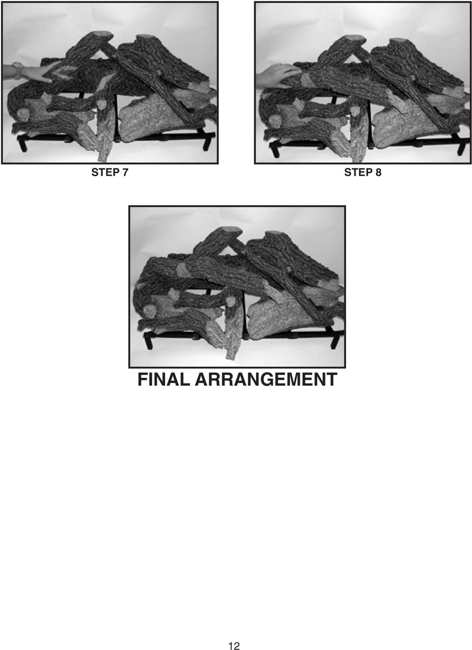
12 STEP 7 STEP 8 FINAL ARRANGEMENT 12
13 LOG PLACEMENT FOR MODEL #HD4240TBF STEP 1 STEP 2 STEP 3 STEP 4 FINAL ARRANGEMENT 13

14 Upon completing the gas line connection, a small amount of air will be in the lines. When first lighting the pilot light, it will take a few minutes for the lines to purge themselves of this air. Once the purging is complete, the pilot and burner will light and operate as indicated in the instruction manual. Subsequent lighting of the appliance will not require such purging. OPERATING GUIDELINES WARNING: CHILDREN AND ADULTS SHOULD BE ALERTED TO THE HAZARDS OF HIGH SURFACE TEMPERATURE AND SHOULD STAY AWAY TO AVOID BURNS OR CLOTHING IGNITION. YOUNG CHILDREN SHOULD BE CAREFULLY SUPERVISED WHEN THEY ARE IN THE SAME ROOM AS THE APPLIANCE. IMPORTANT: TURN OFF GAS BEFORE SERVICING APPLIANCE. IT IS RECOMMENDED THAT A COMPETENT SERVICE TECHNICIAN PERFORM THESE CHECKUPS AT THE BEGINNING OF EACH HEATING SEASON. CAUTION: DURING THE INITIAL PURGING AND SUBSEQUENT LIGHTING, NEVER ALLOW THE GAS VALVE CONTROL KNOB TO REMAIN DEPRESSED IN THE A PILOT POSITION WITHOUT PUSHING THE RED IGNITOR BUTTON AT LEAST ONCE EVERY SECOND. WARNING: THE FLOW OF COMBUSTION AND VENTILATION AIR MUST NOT BE OBSTRUCTED. When lit for the first time, the appliance will emit a slight odor for an hour or two. This is due to paint and lubricants used in the manufacturing process. The main burner flame characteristics are steady, not lifting or floating. Typically, the top 3/4 inch of the pilot generator should be engulfed in the pilot flame. A periodic check of these characteristics is necessary. CAUTION: THE LOGS CAN GET VERY HOT! HANDLE ONLY WHEN COOL MAINTENANCE INSTRUCTIONS IMPORTANT: THE APPLIANCE AREA MUST BE KEPT CLEAR AND FREE FROM COMBUSTIBLE MATERIALS, GASOLINE AND OTHER FLAMMABLE VAPORS AND LIQUIDS. WIRING DIAGRAM Visually inspect pilot periodically. Brush or blow away any dust or lint accumulations. If pilot orifice is plugged, disassembly may be required to remove any foreign material from orifice or tubing. Venting system should be periodically examined by a qualified service technician or agency to ensure proper air flow. 14

15 FOR YOUR SAFETY READ BEFORE LIGHTING WARNING: IF YOU DO NOT FOLLOW THESE INSTRUCTIONS EXACTLY, A FIRE OR EXPLOSION MAY RESULT CAUSING PROPERTY DAMAGE, PERSONAL INJURY OR LOSS OF LIFE. A. This appliance has a pilot. When lighting the pilot, follow these instructions exactly. B. BEFORE LIGHTING smell all around the appliance area for gas. Be sure to smell next to the floor because some gas is heavier than air and will settle on the floor. WHAT TO DO IF YOU SMELL GAS: C. Use only your hand to push in or turn the gas control knob. Never use tools. If the knob will not push in or turn by hand don t try to repair it, call a qualified service technician. Forced or attempted repair may result in a fire or explosion. D. Do not use this appliance if any part has been under water. Immediately call a qualified service technician to inspect the appliance and to replace any part of the gas control system which has been under water. Do not try to light any appliance. Do not touch any electric switch: Do not use any phone in your building. Immediately call your gas supplier from a neighbor s phone. Follow the gas supplier s instructions. If you cannot reach your gas supplier call the fire department. LIGHTING INSTRUCTIONS 1. STOP Read the safety information above first. 2. To access controls, open valve access panel. 3. Turn the control to the OFF position. To do this, you must turn the knob clockwise to the pilot position and then press in and continue turning clockwise to the OFF position. GAS VALVE 4. WAIT FIVE (5) MINUTES TO CLEAR OUT ANY GAS. If you then smell gas, STOP! Follow B in the safety information above. If you don t smell gas, go to next step. 5. The pilot does not require accessing for lighting purposes. The pilot is located inside the combustion chamber. 6. To put the control in the pilot position turn the control knob counter-clockwise to the pilot position. THERMOPILE PILOT BURNER 7. To light the pilot, depress the control knob and then depress the red piezo button until it makes a clicking sound. It may be necessary to repeat this step. If the pilot does not light after Ten seconds, go back to step 3. The control knob should be held Down for a MINUTE after pilot ignition. If the pilot lights, but will not stay lit after two tries, turn the gas control knob to the OFF position and call your Service technician or gas supplier. If the control knob does not pop out when released, STOP - shut off the gas supply to the fireplace control valve and immediately call your service technician or gas supplier 8. After the pilot has been lit, the Burner can be turned on by turning the knob counterclockwise To the ON position. Then turn the ON/OFF switch to the ON position. Note: Damper control lever must be in the open position to ignite. 15

16 1. Open valve access door panel TO TO TURN OFF GAS TO TO APPLIANCE 2. Turn knob clockwise to pilot position then depress and continue turning to OFF 3. Close access door panel LPG (PROPANE) WARNING THE FOLLOWING WARNING APPLIES TO INSTALLATIONS USING L.P. (PROPANE GAS): WARNING: To avoid possible injury, fire and explosion, please read and follow these precautions and all instructions of this appliance before lighting the pilot. This appliance uses L.P. (Propane) gas which is heavier than air and will remain at the floor level if there is a leak. Before lighting, smell at floor level and/or use other means (such as using a soap solution on all piping and connections, using a gas detector, etc.) to check for gas leaks. NOTE: L.P. (Propane) gas can become odorless and CANNOT always be detected by smell. If you smell gas, detect a gas leak or suspect that a gas leak exists, follow these rules: 1. Get all people out of building. 2. DO NOT light matches. DO NOT turn electric lights or switches on or off in area. DO NOT use an electric fan to remove gas from area. DO NOT use a telephone inside of building. 3. Shut off gas at L.P. tank outside of building. 4. Telephone gas company and fire department. Ask instructions. Before hanging up, give your name, address and phone number. DO NOT go back into building. If your L.P. tank runs out of fuel, turn off gas at the appliance. After L.P. tank Is refilled, appliance must be re-lit according to manufacturer s instructions. If the gas control has been exposed to WATER in any way, DO NOT try to use it. It must be replaced. DO NOT attempt repair on gas control or appliance. Tampering is DANGEROUS and voids all warranties. Any component that is found to be faulty, must be replaced with an approved component. IMPORTANT: Always keep the appliance area clear and free from combustible materials, gasoline and other flammable vapors and liquids. Never obstruct the flow of combustion and ventilation air. Keep the front of the appliance clear of all obstacles and materials. To obtain proper operation, it is imperative that the pilot and main burner flame characteristics are steady, not lifting or floating. Typically the top 3/4 inch at the pilot generator should be engulfed in the pilot flame. IMPORTANT - PLEASE NOTE L.P. GAS MODELS MODERATE SOOT ACCUMULATION IS CONSIDERED NORMAL FOR L.P. MODELS. TO KEEP THIS SOOT ACCUMULATION TO A MINIMUM, REDUCE THE FLAME IMPINGEMENT BY SPACING FRONT AND BACK LOGS AS FAR APART AS POSSIBLE. 16
 gas which is heavier than air and will remain at the floor level if there is a leak.")
17 TROUBLE SHOOTING With proper installation and maintenance, your new Gas Fireplace should provide years of trouble-free service. If you do experience a problem, refer to the trouble shooting guide shown below. This guide will assist a qualified service person in the diagnosis of problems and the corrective action to be taken. SYMPTOM POSSIBLE CAUSE CORRECTIVE ACTION 1. Spark ignitor will not light A. Defective ignitor (no 1. Check for spark at pilot after triggering spark at electrode) electrode and pilot; if no spark exist and electrode wire is properly connected, replace ignitor. B. Defective or misaligned 1. Using a match, light electrode at pilot (spark pilot. If pilot lights, turn at electrode) off pilot and trigger the red button again. If pilot lights, an improper gas/ air mixture caused the bad lighting and a longer purge period is recommended. If pilot will not light - check gap at electrode and pilot should be 1/8 inch to have a strong spark. If OK, replace pilot C. No gas or low gas 1. Check remote shut off pressure valves from fireplace. usually there is a valve near the fireplace and sometimes there is a valve near the main. there can be more than one valve between the fireplace and main. 2. Low pressure can be caused by a variety of situations such as a bent line, too narrow diameter of pipe or even low line pressure. Check for kinked lines. If none, consult with Plumber or gas supplier. If L.P. Gas is used you may be out of fuel. important: Any safety screen or guard removed for servicing an appliance must be replaced prior to operating the appliance. 17
 electrode and pilot; if no spark exist and electrode wire is properly connected, replace ignitor. B. Defective or misaligned 1.")
18 TROUBLE SHOOTING (CONT D) SYMPTOM POSSIBLE CAUSE CORRECTIVE ACTION 2. Pilot will not stay lit A. Defective pilot 1. Check pilot, flame must after carefully following generator impinge on pilot generator. lighting instructions. Clean and or adjust pilot for maximum flame impingement on generator. 2. Be sure wire connections from generator at gas valve terminals are tight and generator is fully inserted into pilot bracket. 3. Check thermogenerator with millivolt meter. Take reading at TH-TP and TP terminals of gas valve. Should read 325 millivolts minimum while holding valve knob depressed in pilot position, pilot lit, and ON/OFF switch OFF. Replace faulty generator if reading is below specified minimum. B. Defective valve 1. Connect the millivolt meter probes to the TH-TP and TP terminals on the gas valve. Turn knob to pilot position, depress and light pilot light. If meter reading is greater than 325 m.v. after 30 seconds, the pilot generator is good. If pilot does not stay lit, the valve is defective. If the meter reading is less than 325 m.v., the thermogenerator is defective. C. Open wire connection 1. Check wire continuity and in pilot circuit connections in pilot circuit. 18

19 REPLACEMENT PARTS HD5030-TV THE FOLLOWING REPLACEMENT PARTS ARE AVAILABLE FROM YOUR GOLDEN BLOUNT DEALER ITEM PART # DESCRIPTION ITEM PART # DESCRIPTION 1 HD-101 Gas Valve - N/G 18 HD-118 Step 2 Log 2 HD-102 Gas Valve - LP 19 HD-119 Step 3 Log 3 HD-103 1/4" Pilot Line 20 HD-120 Step 4 Log 4 HD-104 1/2" Burner Line 21 HD-121 Step 5 Log 5 HD-106 Piezo Ignitor 22 HD-122 Step 6 Log 6 HD-105 On/Off Switch 23 HD-123 Step 7 Log 7 HD-107 Pilot Assembly - Nat. 24 HD-124 Step 8 Log 8 HD-108 Pilot Assembly - LP 25 HD-125 Vermiculite (2 Bags LP) 9 HD-109 Thermopile 26 HD-126 Volcanic Rock 10 HD-110 Pilot Assembly Bracket 27 HD-127 Temp Limit Switch 11 HD-111 Burner Orifice NAT 28 HD-128 Damper Switch 12 HD-112 Burner Orifice LP 29 HD-129 Silica Sand (NAT) 13 HD-113 Burner Pan Assembly 30 HD-130 Glowing Embers 14 HD-114 Log Grate 15 HD-115 Step 1 Left Log 16 HD-116 Step 1 Right Log 17 HD-117 Step 1 Back Log 19
 9 HD-109 Thermopile 26 HD-126 Volcanic Rock 10 HD-110 Pilot Assembly Bracket 27 HD-127 Temp Limit Switch 11 HD-111")
20 REPLACEMENT PARTS HD4240-TV THE FOLLOWING REPLACEMENT PARTS ARE AVAILABLE FROM YOUR GOLDEN BLOUNT DEALER ITEM PART # DESCRIPTION ITEM PART # DESCRIPTION 1 HD-101 Gas Valve - N/G 18 HD-218 Step 3 Log 2 HD-102 Gas Valve - LP 19 HD-219 Step 1 Left Log 3 HD-103 1/4" Pilot Line 20 HD-220 Step 1 Right Log 4 HD-104 1/2" Burner Line 21 HD-221 Step 1 Back 5 HD-106 Piezo Ignitor 22 6 HD-105 On/Off Switch 23 7 HD-107 Pilot Assembly - Nat HD-108 Pilot Assembly - LP 25 HD-125 Vermiculite (2 Bags LP) 9 HD-109 Thermopile 26 HD-126 Volcanic Rock 10 HD-110 Pilot Assembly Bracket 27 HD-127 Temp Limit Switch 11 HD-211 Burner Orifice NAT 28 HD-128 Damper Switch 12 HD-112 Burner Orifice LP 29 HD-129 Silica Sand (NAT) 13 HD-213 Burner Pan Assembly 30 HD-130 Glowing Embers 14 HD-214 Log Grate 15 HD-215 Step 4 Bottom Log 16 HD-216 Step 4 Top Log 17 HD-217 Step 2 Log
 9 HD-109 Thermopile 26 HD-126 Volcanic Rock 10 HD-110 Pilot Assembly Bracket 27 HD-127 Temp Limit Switch 11 HD-211 Burner Orifice NAT")
21 TWO YEAR LIMITED WARRANTY This warranty is limited to top-vent gas fireplaces manufactured and assembled by Golden Blount. If Golden Blount finds that any part or portion of the fireplace covered by this warranty is defective in material or workmanship under normal use and service as described in the installation and operating instructions, Golden Blount will take the following actions: 1. Within the first year from the date of installation, Golden Blount shall, at its option replace or repair any such defect in material or workmanship, at Golden Blount s expense, including a reasonable labor allowance as determined by Golden Blount. Golden Blount shall not be responsible for any other labor costs, or expenses, including indirect, incidental or consequential damages. 2. During the second year after the date of installation, Golden Blount shall supply replacement parts at the current wholesale price, but Golden Blount shall not be responsible for any labor, transportation, or the indirect, incidental, or consequential damages. 3. All factory optional components or accessories found to be defective will be repaired or replaced without charge during the first year after installation. Golden Blount may discharge its entire warranty liability by refunding the price of the product. Products made by other manufacturers, sold with the fireplace or thereafter are not covered by this limited warranty. The use of other unauthorized components will make this warranty null and void. This limited warranty will be void if the appliance is not installed by a qualified installer and according to the installation instructions. The limited warranty also is void if the fireplace is not operated, at all times, according to the operating instructions furnished. Some states do not allow exclusion of incidental or consequential damages or limits on the duration of implied warranties so these limitations may not apply to you. Golden Blount reserves the right to investigate any and all claims against this warranty and to decide on the method of settlement. Golden Blount is not responsible for warranty work completed without obtaining Golden Blount s consent. Golden Blount employees and dealers have no right to alter this written warranty. Warranty Information Please be able to provide the following information when communicating with Golden Blount or its dealers or distributors regarding service under this warranty. Model no. Serial No. Date of Purchase Golden Blount 4301 Westgrove Dr. Addison, TX (972)
INSTALLATION AND OPERATIONS GUIDE FOR GRAND CANYON GAS LOG SYSTEMS
 INSTALLATION AND OPERATIONS GUIDE FOR GRAND CANYON GAS LOG SYSTEMS Installation and service must be provided by a qualified installer, service agency or gas supplier Grand Canyon Gas Logs, logs are made
NOTE! READ INSTRUCTIONS FULLY BEFORE INSTALLING OR OPERATING.
 INSTALLATION AND OPERATION GUIDE FOR HARGROVE GAS LOGS PROPANE GAS ADEQUATE FIREPLACE VENTILATION IS REQUIRED FOR SAFETY. GAS LOGS MUST BE INSTALLED BY PERSONNEL QUALIFIED FOR INSTALLING GAS APPLIANCES.
American Fireglass Outdoor Fire pit kit information. General instructions/warnings for outdoor gas pan and burner systems
 American Fireglass Outdoor Fire pit kit information General instructions/warnings for outdoor gas pan and burner systems We strongly recommend that our burner products be installed by a licensed and certified
Your safety and the safety of others are very important.
 NATURAL GAS TO PROPANE CONVERSION KIT 090 INSTALLATION INSTRUCTIONS FOR ALTITUDES 0 -,00 FT. ONLY PROPANE CONVERSION KIT SAFETY... INSTALLATION REQUIREMENTS... Tools and Parts... LP Gas Requirements...
36G22, 36G23, 36G24 & 36G52 36J22, 36J23, 36J24 & 36J52 DSI and HSI Single Stage Combination Gas Valve
 Operator: Save these instructions for future use! FAILURE TO READ AND FOLLOW ALL INSTRUCTIONS CAREFULLY BEFORE INSTALLING OR OPERATING THIS CONTROL COULD CAUSE PERSONAL INJURY AND/OR PROPERTY DAMAGE. DESCRIPTION
HOW MUCH FUEL DOES A GAS STOVE CONSUME AND HOW MUCH DOES IT COST TO OPERATE?
 WHAT IS A BTU? The standard energy measurement is the BTU (British Thermal Unit). Each BTU unit is determined by the amount of thermal energy required to raise the temperature of one pound of water by
USER S, MAINTENANCE and SERVICE INFORMATION MANUAL
 CONTENTS SAFETY INFORMATION................ 2 FOR YOUR SAFETY....................... 2 SYSTEM OPERATION.................. 2 THERMOSTATS........................... 2 INTERMITTENT IGNITION DEVICE...........
San josé OWNER S MANUAL
 San josé OWNER S MANUAL Assembling & operating manual San josé 30 mbar - PORTABLE GAS BARBECUE 1. 2. 3. Improper installation, adjustment, alteration, service or maintenance can injury or property damage.
Operator: Save these instructions for future use!
 WHITE-RODGERS 36C01 Combination Gas Valves (24 Volt and 120 Volt Models) INSTALLATI INSTRUCTIS FAILURE TO READ AND FOLLOW ALL INSTRUCTIS CAREFULLY BEFORE INSTALLING OR OPERATING THIS CTROL COULD CAUSE
GAS SAFETY PRECAUTIONS
 GAS SAFETY PRECAUTIONS Instructions on what to do when a user smells gas can be obtained from the local gas supplier. These instructions must be posted in a prominent location where the unit is to be operated.
orlando OWNER S MANUAL
 orlando OWNER S MANUAL 2 Assembling & operating manual Orlando 30 mbar - PORTABLE GAS BARBECUE 1. 2. 3. Improper installation, adjustment, alteration, service or maintenance can injury or property damage.
THC 85 INDUSTRIAL / COMMERCIAL SPACE HEATER
 THC 85 INDUSTRIAL / COMMERCIAL SPACE HEATER Certified to / Certifié à CGA 2.14 M2000 Conforms to / Conforme à ANSI std Z83.7 2000 Suitable for indoor or outdoor installation / Unvented / Unattended Type
CROWN BOILER COMPANY BWF SERIES BOILER CATEGORY I VENT KIT INSTALLATION AND OPERATING INSTRUCTIONS
 CROWN BOILER COMPANY BWF SERIES BOILER CATEGORY I VENT KIT INSTALLATION AND OPERATING INSTRUCTIONS WARNING Improper installation, adjustment, alteration, service, or maintenance of this product can cause
CARING FOR YOUR WATER HEATER
 http://waterheatertimer.org/troubleshoot-rheem-tankless-water-heater.html Water Heater Inspections CARING FOR YOUR WATER HEATER Venting System (Direct Vent Only) The venting system should be inspected
SL280UHV SERIES GAS FURNACE WARNING
 2010 Lennox Industries Inc. Dallas, Texas, USA 506677 01 11/2010 Supersedes 506409 01 SL280UHV SERIES GAS FURNACE Litho U.S.A. FIRE OR EXPLOSION HAZARD. Failure to follow safety warnings exactly could
G670 Intermittent Pilot Ignition Controls
 Installation Sheets Manual 121 Gas Combustion Combination Controls and Systems Section G Technical Bulletin Issue Date 0300 Intermittent Pilot Ignition Controls Figure 1: Intermittent Pilot Ignition Control
FOR THE FOLLOWING MODELS: EE-8075W EE-8075O EE-8075R EE-8075BK
 FIREPLACE HEATER FOR THE FOLLOWING MODELS: EE-8075W EE-8075O EE-8075R EE-8075BK If you have any questions about the operation of your fireplace heater, please contact Crane Customer Care. Toll Free: 888-599-0992
Cleaning Instructions, Pilot Replacement and Valve Change. Model No.: 233010 Natural Gas
 Cleaning Instructions, Pilot Replacement and Valve Change Model No.: 233010 Natural Gas 8mm open-end wrench 9mm open-end wrench 10mm open-end wrench 12mm open-end wrench 13mm open-end wrench Phillips screw
VENTED NATURAL GAS LOGS
 VENTED NATURAL GAS LOGS MODEL #WAN18N-2 WAN24N-2 CAUTION - FOR YOUR SAFETY WARNING: IF THE INFORMATION IN THIS MANUAL IS NOT FOLLOWED EXACTLY, A FIRE MAY RESULT CAUSING PROPERTY DAMAGE, PERSONAL INJURY,
IMPORTANT INSTRUCTIONS & OPERATING MANUAL. Houston 50 Inch Electric Wall Mounted Fireplace Black / White
 IMPORTANT INSTRUCTIONS & OPERATING MANUAL Houston 50 Inch Electric Wall Mounted Fireplace Black / White Model Number:MFE5050BK Model Number:MFE5050WH Read these instructions carefully before attempting
Owner Retain this manual in a safe place to provide your serviceman information if it becomes necessary.
 INSTALLATION, OPERATING AND SERVICE MANUAL FOR EASY RADIANT WORKS HEATWAVE MODEL GH-25-40 GAS FIRED, VENTED INFRARED TUBE HEATER FOR RESIDENTIAL & COMMERCIAL / INDUSTRIAL APPLICATIONS. For Your Safety
ASK THE EXPERT: Burner Troubleshooting Information & Maintenance
 ASK THE EXPERT: Burner Troubleshooting Information & Maintenance The burner is the heart of your BBQ. It is subject to a number of conditions that can cause damage, and lead to potential safety issues.
!"" #$% "!&' ( ( ) *
 *") !"" #$% "!&' (( ) * G Whiz Gas Popper Instruction Manual Model #5908 Part No. 74874 Revised October 1997 Cincinnati, OH 45241-4807 USA GAS SAFETY PRECAUTIONS Instructions on what to do when a user smells
!"" #$% "!&' (( ) * G Whiz Gas Popper Instruction Manual Model #5908 Part No. 74874 Revised October 1997 Cincinnati, OH 45241-4807 USA GAS SAFETY PRECAUTIONS Instructions on what to do when a user smells
Cleaning Instructions for Burner, Pilot Assembly, and Emitter Screen. Series: 150000 200605 LP Gas
 Cleaning Instructions for Burner, Pilot Assembly, and Emitter Screen Series: 150000 200605 LP Gas Tools needed Bottle brush Non-abrasive scouring pad Small utility brush Heavy-duty pipe cleaners Air hose
INSTALLATION INSTRUCTIONS
 INSTALLATION INSTRUCTIONS VGBQ SERIES CONVERSION KIT VIKING RANGE CORPORATION 111 Front Street Greenwood, Mississippi (MS) 38930 USA (662) 455-1200 IMPORTANT: PLEASE READ AND FOLLOW 1. Before beginning,
OBSOLETE. VS8420 Millivolt Gas Valve
 APPLICATION The VS8420 Millivolt Gas Valve is compact and has a 60,000 Btuh capacity (1 in. pressure drop for straightthrough configuration). The design makes it ideal for fireplace and space heating applications.
AUTOMATIC REMOTE LIGHTING SAFETY PILOT SYSTEM FOR NATURAL OR PROPANE GAS EPK-1 PILOT KITS
 INSTALLATION & OWNER S MANUAL AUTOMATIC REMOTE LIGHTING SAFETY PILOT SYSTEM FOR NATURAL OR PROPANE GAS Models: EPK-1(M)(P) FEATURES: INTERMITTENT PILOT IGNITION NON-STANDING FLAME-SENSING PILOT MANUAL
The growing popularity of Gas Fireplaces has created a demand for an ever increasing array of styles and sizes to fit every decor and budget.
 Consumer Information Guide to Gas Fireplaces A Gas Fireplace gives you all the ambiance, warmth and comfort of a traditional wood-burning fireplace. They are convenient, easy to use and cost effective.
Propane Conversion Kit PROPANE CONVERSION KIT INSTALLATION MANUAL
 Propane Conversion Kit Supersedes: 145.25-IOM2 (708) Form 145.25-IOM2 (908) PROPANE CONVERSION KIT INSTALLATION MANUAL "LPKIT " - PROPANE CONVERSION KIT Kits are available for field conversion from natural
HEATMASTER, LLC AMERICAN GAS LOG
 Models: HEATMASTER, LLC AMERICAN GAS LOG DG-SS-18/24/30NG AGL-SS-18/24 NG H-SS-24NG HM2-SS-24NG Outdoor Burner/Hearth Kits For use use with Natural gas only Installation Instructions Installation and service
OBSOLETE. VS8510,VS8520 Millivolt Gas Valve
 APPLICATION The VS8510, VS8520 Millivolt Gas Valve is compact and has a 60,000 Btuh capacity (1 in. pressure drop for straight through configuration). Its design makes it ideal for fireplace and space
2010 Residential Water Heater Replacement Check List
 2010 Residential Water Heater Replacement Check List The intent of this check list is to provide installers a general reference for the enforcement of code requirements in the Greater San Diego Area. This
TWO BURNER PROPANE CAMPING STOVE
 OWNER S MANUAL ASSEMBLY AND OPERATING INSTRUCTIONS TWO BURNER PROPANE CAMPING STOVE WARNING READ AND FOLLOW ALL WARNINGS AND INSTRUCTIONS IN THIS MANUAL TO AVOID PERSONAL INJURY OR PROPERTY DAMAGE. Propane
Cleaning Instructions for Burner, Pilot Assembly, and Emitter Screen Series: 220000-450000
 Cleaning Instructions for Burner, Pilot Assembly, and Emitter Screen Series: 220000-450000 10 mm open end wrench 12 mm open end wrench 9/16 open end wrench 5/8 open end wrench 11/16 open end wrench 9/16
Ducoterra Radiant Heating Panel Installation Manual
 Ducoterra Radiant Heating Panel Installation Manual 1. Introduction Your new radiant heating panels are designed to heat living and working spaces rapidly and efficiently by radiant heating. Like the sun,
Instantaneous gas water heater
 Instantaneous gas water heater Models W 125...T1 installation operation maintenance The Bosch instantaneous water heater is a high efficiency, space saving answer to your water heating needs. All Bosch
ASX7-4-IOM-7 J30-08579
 INSTALLATION INSTRUCTIONS 4" COMBUSTION AIR INLET KIT TUBULAR GAS FIRED DIRECT SPARK PROPELLER UNIT HEATERS UNIT CONVERSION & CATEGORY III VENTING FOR SEPARATED COMBUSTION For 30,000 to 75,000 BTU/HR SUPPLEMENT
OUTDOOR GAS FIREPLACE USER GUIDE North America 630165_2 EF5000. www.escea.net
 OUTDOOR GAS FIREPLACE USER GUIDE North America 630165_2 EF5000 www.escea.net Any service work carried out on this appliance must only be done by a recognised escea technician or authorized personnel. The
MAJESTIC. OUTDOOR / INDOOR WOOD FIREPLACES Model: ODSR36A OWNERS INSTALLATION & OPERATING INSTRUCTIONS. KEEP THESE INSTRUCTIONS FOR FUTURE REFERANCE.
 MAJESTIC OUTDOOR / INDOOR WOOD FIREPLACES Model: ODSR36A OWNERS INSTALLATION & OPERATING INSTRUCTIONS. KEEP THESE INSTRUCTIONS FOR FUTURE REFERANCE. CONTENTS Part 1: Safety Information Part 2: Installation
Instruction Manual for Residential Manufactured Home Gas Water Heaters
 Instruction Manual for Residential Manufactured Home Gas Water Heaters FOR USE ONLY IN MANUFACTURED HOMES GAMA certification applies to all residential gas water heaters with capacities of 20 to 100 gallons
Gas-Fired, Residential Storage Type Water Heaters
 Consulting, Resource, Education, Training, and Support Services for Home Inspectors A candle loses no light when it lights another candle. Gas-Fired, Residential Storage Type Water Heaters Most inspectors
RESIDENTIAL GAS-FIRED WATER HEATERS OWNER S MANUAL INSTALLATION AND OPERATING INSTRUCTIONS
 RESIDENTIAL GAS-FIRED WATER HEATERS (EQUIPPED WITH FVIR TECHNOLOGY) OWNER S MANUAL INSTALLATION AND OPERATING INSTRUCTIONS This water heater IS NOT design certified for installation in a manufactured (mobile)
INSTALLATION MANUAL GAS COOKTOP. Please read this guide thoroughly before installation. www.lge.com. P/No.: MFL62725502
 ENGL ISH ESPA ÑOL INSTALLATION MANUAL GAS COOKTOP Please read this guide thoroughly before installation. P/No.: MFL62725502 www.lge.com READ ALL INSTRUCTIONS BEFORE INSTALLATION IN THE COMMONWEALTH OF
MODELS BR517R & BR517S (G.C. 32-032-11 & 32-032-12) & ULTIMATE TURBOCHIM* & SUPERFLAME RF* Rear & Side Fan Flued Inset Gas Fires
 & ULTIMATE TURBOCHIM* & SUPERFLAME RF* Rear & Side Fan Flued Inset Gas Fires") O W N E R G U I D E MODELS BR517R & BR517S (G.C. 32-032-11 & 32-032-12) & ULTIMATE TURBOCHIM* & SUPERFLAME RF* Rear & Side Fan Flued Inset Gas Fires *Covered by GB Patent 2.202.622.B This Owner Guide is
O W N E R G U I D E MODELS BR517R & BR517S (G.C. 32-032-11 & 32-032-12) & ULTIMATE TURBOCHIM* & SUPERFLAME RF* Rear & Side Fan Flued Inset Gas Fires *Covered by GB Patent 2.202.622.B This Owner Guide is
Tankless Water Heater
 Tankless Water Heater USER S INFORMATION MANUAL Models WGRTNG199 / WGRTLP199 WGRTCNG199 / WGRTCLP199 NOTICE: Westinghouse reserves the right to make product changes or updates without notice and will not
Troubleshoot resources for homeowner http://waterheatertimer.org/troubleshoot-bosch-tankless-water-heater.html
 Troubleshoot resources for homeowner http://waterheatertimer.org/troubleshoot-bosch-tankless-water-heater.html Installation / Operating Instructions GOOD.BEETER>BOSCH Water Wizard 600 Continuous Flow Gas
Indirect-Fired Storage Water Heater Models WH-30 through WH-80 INSTALLATION AND OPERATING INSTRUCTIONS
 Indirect-Fired Storage Water Heater Models WH-30 through WH-80 INSTALLATION AND OPERATING INSTRUCTIONS Contents Page Ratings and Specifications..................... 2 Installation Requirements......................
UNVENTED (VENT-FREE) GAS LOG HEATER OWNER S OPERATION AND INSTALLATION MANUAL. BGe18NR, BGe18PR, BGe2436NR and BGe2436PR
 GAS LOG HEATER OWNER S OPERATION AND INSTALLATION MANUAL. BGe18NR, BGe18PR, BGe2436NR and BGe2436PR") UNVENTED (VENT-FREE) GAS LOG HEATER OWNER S OPERATION AND INSTALLATION MANUAL PFS US Remote-Ready BURNER SYSTEM MODELS BG18NR, BG18PR, BG2436NR, BG2436PR, BGe18NR, BGe18PR, BGe2436NR and BGe2436PR FOr
UNVENTED (VENT-FREE) GAS LOG HEATER OWNER S OPERATION AND INSTALLATION MANUAL PFS US Remote-Ready BURNER SYSTEM MODELS BG18NR, BG18PR, BG2436NR, BG2436PR, BGe18NR, BGe18PR, BGe2436NR and BGe2436PR FOr
THERMOSTATIC MIXING VALVE TRIM K-T9493, K-T9494
 THERMOSTATIC MIXING VALVE TRIM K-T9493, K-T9494 1. BEFORE YOU BEGIN IMPORTANT INSTRUCTIONS READ AND SAVE FOR THE CONSUMER WARNING: Risk of scalding or other severe injury. Before completing installation,
INDIRECT WATER HEATER. Installation and Operating Instruction Manual
 INDIRECT WATER HEATER Installation and Operating Instruction Manual Maximum supply temperature to heat exchanger must not exceed 180 F (82 C). Safety Warning: Indirect water heaters are heat-producing
Electric Fryers Instruction Manual Models: 8047D, 8048D, 8049D, 8050D, 8051D 8066, 8068, 8068FL, 8073, 8073BF and 8075
 Part No. 89047 Electric Fryers Instruction Manual Models: 8047D, 8048D, 8049D, 8050D, 8051D 8066, 8068, 8068FL, 8073, 8073BF and 8075 Cincinnati, OH 45241-4807 USA ELECTRIC FRYER SAFETY PRECAUTIONS Installation
Cooktop Low-Profile Ventilation Hoods
 INSTALLATION GUIDE Cooktop Low-Profile Ventilation Hoods Contents Wolf Cooktop Low-Profile Ventilation Hoods........ 3 Cooktop Low-Profile Hood Specifications.......... 4 Cooktop Low-Profile Hood Installation............
MICA HEATER INSTRUCTION MANUAL Model No: UHM-786 230V 50Hz 2200W
 MICA HEATER INSTRUCTION MANUAL Model No: UHM-786 230V 50Hz 2200W Safety Precautions To reduce the risk of personal injury or damage to property, basic safety precautions must be observed including the
DIRECT VENT GAS FURNACE FOR THROUGH THE WALL OR WINDOW INSTALLATION
 DIRECT VENT GAS FURNACE FOR THROUGH THE WALL OR WINDOW INSTALLATION OWNER'S OPERATION AND INSTALLATION MANUAL SA25N SA25P SA40N SA40P WARNING: If the information in these instructions is not followed exactly,
TWO BURNER PROPANE CAMPING STOVE
 842-A100-S_CmpStove.qxd 2/10/06 11:20 AM Page 1 OWNER S MANUAL TWO BURNER PROPANE CAMPING STOVE FAILURE TO FOLLOW ALL S AND INSTRUCTIONS IN THIS MANUAL COULD LEAD TO PERSONAL INJURY, INCLUDING DEATH. RETAIN
Your safety and the safety of others are very important.
 NATURAL GAS TO PROPANE CONVERSION KIT ALPKT7- INSTALLATION INSTRUCTIONS PROPANE CONVERSION KIT SAFETY... INSTALLATION REQUIREMENTS... Tools and Parts... LP Gas Requirements... INSTALLATION INSTRUCTIONS...
ecomax Instructions for use Wall hung room sealed fan assisted condensing boilers For the user
 For the user Instructions for use ecomax Wall hung room sealed fan assisted condensing boilers ecomax 63/ E ecomax 68/ E ecomax 6/ E ecomax 635 E ecomax 84/ E ecomax 88/ E ecomax 835 E GB Table of contents
VENT-FREE GAS LOG SET
 VENT-FREE GAS LOG SET MODEL # VFL-CY24DR VFL-HT24DR VFL-CY30DR VFL-HT30DR WARNING: This appliance is equipped for (Natural and Propane) gas. Field conversion is not permitted other than between natural
SERVICE MANUAL. Flammable Vapor Ignition Resistant Water Heaters. Gas Water Heaters. Troubleshooting Guide and Instructions for Service
 http://waterheatertimer.org/how-to-troubleshoot-gas-water-heater.html Flammable Vapor Ignition Resistant Water Heaters Gas Water Heaters SERVICE MANUAL Troubleshooting Guide and Instructions for Service
Baxi Combi 80e & 105e
 Baxi Combi 8e & 15e Please keep these instructions safe. Should you move house, please hand them over to the next occupier. Gas Fired Wall Mounted Combination Boiler User s Operating Instructions Natural
Instruction Manual for Residential Gas Water Heaters
 Instruction Manual for Residential Gas Water Heaters NOT FOR USE IN MANUFACTURED (MOBILE) HOMES GAMA certification applies to all residential gas water heaters with capacities of 20 to 100 gallons with
Firewall. Propane flame projector Safety instructions and operating manual
 Firewall Propane flame projector Safety instructions and operating manual TBF-PyroTec GmbH Lichterfelder Str. 5A 21502 Geesthacht Tel.: +49(0)4152 157 9950 [email protected] www.tbf-pyrotec.de 1 Flame
Ceiling Mount Air Handler Manual
 www.surna.com 303.993.5271 Ceiling Mount Air Handler Manual Models: CMAH12, CMAH18, CMAH24, CMAH30, CMAH36, CMAH48, CMAH60 Revised: September 2014 Table of Contents Warranty Information 4 Limited Warranty
PURCHASED. IF YOU ARE UNSUCCESSFUL, PLEASE WRITE TO THE COMPANY LISTED ON THE RATING PLATE ON THE WATER HEATER.
 Instruction Manual RESIDENTIAL GAS WATER HEATERS FOR USE ONLY IN MANUFACTURED HOMES GAMA certification applies to all residential gas water heaters with capacities of 20 to 100 gallons with input rating
G26 Corp. 9721-L11 Revised 07-2001 LENNOXOEMPARTS.COM. Service Literature G26 SERIES UNITS
 Service Literature G26 SERIES UNITS G26 series units are high-efficiency upflow gas furnaces manufactured with DuralokPlust aluminized steel clamshell-type heat exchangers. G26 units are available in heating
NAVIEN AMERICA INC. 17855 FITCH AVENUE
 Navien America Inc. Specification Details for the Navien models: CC-240 CC-240A For Potable Water Heating and Space Heating NAVIEN AMERICA INC. 17855 FITCH AVENUE IRVINE, CALIFORNIA, USA 92614 Toll Free:
30" GAS RANGE INSTALLATION INSTRUCTIONS (For Models with Sealed Top Burners)
") INSTALLATION AND SERVICE MUST BE PERFORMED BY A QUALIFIED INSTALLER. IMPORTANT: SAVE FOR LOCAL ELECTRICAL INSPECTOR'S USE. READ AND SAVE THESE INSTRUCTIONS FOR FUTURE REFERENCE. If the information in this
INSTALLATION AND SERVICE MUST BE PERFORMED BY A QUALIFIED INSTALLER. IMPORTANT: SAVE FOR LOCAL ELECTRICAL INSPECTOR'S USE. READ AND SAVE THESE INSTRUCTIONS FOR FUTURE REFERENCE. If the information in this
SPARK MODERN FIRES RETROFIT FIRE RIBBON VENTED DECORATIVE APPLIANCE OWNER S OPERATION AND INSTALLATION MANUAL
 SPARK MODERN FIRES RETROFIT FIRE RIBBON VENTED DECORATIVE APPLIANCE OWNER S OPERATION AND INSTALLATION MANUAL Z21.60b-2004 / CSA 2.26b-2004 APPROVED 321-L-06-5 WARNING: If the information in this manual
UNVENTED (VENT-FREE) INFRARED GAS HEATER SAFETY INFORMATION AND INSTALLATION MANUAL
 INFRARED GAS HEATER SAFETY INFORMATION AND INSTALLATION MANUAL") UNVENTED (VENT-FREE) INFRARED GAS HEATER SAFETY INFORMATION AND INSTALLATION MANUAL Model: IWH10NLTB Model:IWH16NLTB WARNING: If the information in this manual is not followed exactly, a fi re or explosion
UNVENTED (VENT-FREE) INFRARED GAS HEATER SAFETY INFORMATION AND INSTALLATION MANUAL Model: IWH10NLTB Model:IWH16NLTB WARNING: If the information in this manual is not followed exactly, a fi re or explosion
INSTALLATION INSTRUCTIONS - FREESTANDING GAS RANGE
 INSTALLATION AND SERVICE MUST BE PERFORMED BY A QUALIFIED INSTALLER. IMPORTANT: SAVE FOR LOCAL ELECTRICAL INSPECTOR'S USE. READ AND SAVE THESE INSTRUCTIONS FOR FUTURE REFERENCE. If the information in this
USER S INFORMATION MANUAL
 USER S INFORMATION MANUAL UPFLOW, DOWNFLOW, UPFLOW/HORIZONTAL & HORIZONTAL ONLY INDUCED DRAFT GAS FURNACES Recognize this symbol as an indication of Important Safety Information If the information in this
Installation Operation & Maintenance Manual
 www.montigo.com Operation & Maintenance Manual Check local codes and read all instructions prior to installation. EDVPV BF-Series Wall SS Power Gas Fireplace Vent System EDVPV47 EDVPV58 Warning: Improper
30" GAS RANGE INSTALLATION INSTRUCTIONS (For Models with Sealed Top Burners)
") INSTALLATION AND SERVICE MUST BE PERFORMED BY A QUALIFIED INSTALLER. IMPORTANT: SAVE FOR LOCAL ELECTRICAL INSPECTOR'S USE. READ AND SAVE THESE INSTRUCTIONS FOR FUTURE REFERENCE. If the information in this
INSTALLATION AND SERVICE MUST BE PERFORMED BY A QUALIFIED INSTALLER. IMPORTANT: SAVE FOR LOCAL ELECTRICAL INSPECTOR'S USE. READ AND SAVE THESE INSTRUCTIONS FOR FUTURE REFERENCE. If the information in this
NITROUS TRANSFER PUMP INSTRUCTIONS
 NITROUS TRANSFER PUMP INSTRUCTIONS SAFETY TIPS Never directly inhale nitrous oxide. When inhaled in large quantities, nitrous oxide can cause respiratory ailments or in extreme cases, death by suffocation.
Bottom Loading Water Dispenser
 Bottom Loading Water Dispenser Model # 601000 TO REDUCE THE RISK OF INJURY AND PROPERTY DAMAGE, USER MUST READ THIS MANUAL BEFORE ASSEMBLING, INSTALLING & OPERATING DISPENSER. SAVE THIS MANUAL FOR FUTURE
http://waterheatertimer.org/how-to-troubleshoot-gas-water-heater.html
 http://waterheatertimer.org/how-to-troubleshoot-gas-water-heater.html BURNER PROBLEM POSSBLE CAUSE(S) CORRECTVE ACTON WLL NOT GNTE 1. Pilot not tit Thermostat set too tow 3. Main burner line clogged Non-functioning
IMPORTANT SAFETY INSTRUCTIONS WARNING READ AND SAVE THESE OPERATING AND SAFETY INSTRUCTIONS BEFORE USING THIS HEATER.
 THERMAWAVE CERAMIC HEATER Model HZ-850 Series Model HZ-860 Series IMPORTANT SAFETY INSTRUCTIONS WARNING READ AND SAVE THESE OPERATING AND SAFETY INSTRUCTIONS BEFORE USING THIS HEATER. Warning Failure to
DTM04 TANK MONITOR DTM08 TANK MONITOR Dtm12 TANK MONITOR. Installation and Operation Manual
 DTM04 TANK MONITOR DTM08 TANK MONITOR Dtm12 TANK MONITOR Installation and Operation Manual 1 ENGLISH Safety Instructions 2 Features 2-3 Specifications 3 Installation 4-5 Wiring Diagrams 6-7 Warranty 8
TB-A028-06 - A. O. SMITH - FVIR INTELLI-VENT TROUBLESHOOTING CHART # LED STATUS PROBLEM SOLUTION
 1 2 3 4 5 Inadequate or no earth ground sensed by the Intelli-Vent control. Power supply to Intelli-Vent control has reversed polarity. Pressure switch circuit remaining closed for more than 5 seconds
PROPANE CONSTRUCTION HEATER
 Dyna-Glo, Dyna-Glo Pro Dyna-Glo Delux PROPANE CONSTRUCTION HEATER USER S MANUAL AND OPERATING INSTRUCTIONS MODEL # RA18LPDG, RA18LPDGD, RA18LPDGP, RA18LPA, RA18LPB, and RA18LPC C US CSA 2.14b-2009, ANS
3 IN 1 BATHROOM HEATER
 3 IN 1 BATHROOM HEATER MODEL NO.: A515 - SH MINI FUNCTION: HEATER, EXHAUST FAN AND LIGHT Dear customers, Thank you for selecting the AUPU 3 in 1 Bathroom Heater. Please read all instructions before commencing
Portable Air Conditioner
 Portable Air Conditioner Owner's Manual Model:3 in 1 12,000 Btu/h Series 3 Please read this owner s manual carefully before operation and retain it for future reference. CONTENTS 1. SUMMARY...1 2. PORTABLE
English. Symbols used to mark instructions...3. Congratulations...5 Getting the best results...5. Warnings...6 Operating Procedure...
 2 Contents Components Attachments Guidance Installation Operation Maintenance Service Technical Troubleshooting Symbols used to mark instructions...3 Included Attachments...4 Congratulations...5 Getting
Electronic Ignition Fire Pit Insert
 Electronic Ignition Fire Pit Insert Installation & Operation Instructions Select Models Certified by CSA International* Meets: ANSI Z21.97-2012 CSA 2.41-2012 See Bottom of This Page Installation We suggest
Ontario Fire Code SECTION 5.13 DIP TANKS. Illustrated Commentary. Office of the Ontario Fire Marshal
 Ontario Fire Code SECTION 5.13 DIP TANKS Illustrated Commentary Office of the Ontario Fire Marshal Dip Tanks Illustrated Commentary 1 5.13.1. Location 5.13.1.1. Dip tank operations involving flammable
USER MANUAL. Bottom Loading Bottled Water Dispenser SAVE THIS MANUAL FOR FUTURE USE. Model # 900172
 Model # 900172: Page 1 USER MANUAL Bottom Loading Bottled Water Dispenser Model # 900172 TO REDUCE THE RISK OF INJURY AND PROPERTY DAMAGE, USER MUST READ THIS MANUAL BEFORE ASSEMBLING, INSTALLING & OPERATING
COMMERCIAL COOKING HOODS, VENTILATION & FIRE SUPPRESSION SYSTEM GUIDELINES AND PROCEDURES
 COMMERCIAL COOKING HOODS, VENTILATION & FIRE SUPPRESSION SYSTEM GUIDELINES AND PROCEDURES These guidelines are to be used for ALL commercial cooking hoods, ventilation systems and related fire suppression
OWNER S MANUAL FORCE 10 MARINE COMPANY 23080 HAMILTON ROAD RICHMOND, BC CANADA V6V 1C9 TEL: (604) 522-0233 FAX: (604) 522-9608
 522-0233 FAX: (604) 522-9608") Electric Water Heater OWNER S MANUAL FORCE 10 MARINE COMPANY 23080 HAMILTON ROAD RICHMOND, BC CANADA V6V 1C9 TEL: (604) 522-0233 FAX: (604) 522-9608 If your water Heater is Damaged or you have questions
Electric Water Heater OWNER S MANUAL FORCE 10 MARINE COMPANY 23080 HAMILTON ROAD RICHMOND, BC CANADA V6V 1C9 TEL: (604) 522-0233 FAX: (604) 522-9608 If your water Heater is Damaged or you have questions
Installation Instructions Horizon Natural Draft Electronic Ignition Gas Fireplaces
 Installation Instructions Horizon Natural Draft Electronic Ignition Gas Fireplaces Installation Instructions Kemlan Natural Draft Electronic Ignition 3 Sided Gas Fireplaces Natural Draft Electronic Ignition
Name Of Occupancy Date. Yes No Describe
 FIRE PREVENTION INSPECTION CHECKLIST For Class A Occupancy (For Assembly Buildings, Bars, Restaurants, Gyms, Churches, Arenas, Theatres or wherever people gather) Name Of Occupancy Date Physical Address
BATHROOM HEATER. User's Manual. Page 2...A515 Page 9...A716
 BATHROOM HEATER User's Manual Page 2...A515 Page 9...A716 BATHROOM HEATER User's Manual A515 SAVE THESE INSTRUCTIONS AND READ ALL INSTRUCTIONS BEFORE USING THE HEATER. Dear customers, Thank you for selecting
Natural Gas Appliance Testing Action Guidelines (Non ESA/Low Income 5 )
") Natural Gas Appliance Testing Action Guidelines (n ESA/Low Income 5 ) The purpose of these Action Guidelines is to describe the actions participating contractors and/or inspectors should take in the event
Natural Gas Appliance Testing Action Guidelines (n ESA/Low Income 5 ) The purpose of these Action Guidelines is to describe the actions participating contractors and/or inspectors should take in the event
Use & Care Manual. Electric Tankless Water Heaters. With Installation Instructions for the Installer AP15447 (10/10)
") Use & Care Manual With Installation Instructions for the Installer Electric Tankless Water Heaters The purpose of this manual is twofold: one, to provide the installer with the basic directions and recommendations
Use & Care Manual With Installation Instructions for the Installer Electric Tankless Water Heaters The purpose of this manual is twofold: one, to provide the installer with the basic directions and recommendations
DRYER VENTING SPECIFICATIONS DRYER SAFETY
 DRYER VENTING SPECIFICATIONS Table of Contents DRYER SAFETY...1 INSTALLATION REQUIREMENTS...4 Venting Requirements...5 DRYER INSPECTION AND CLEANING...7 Frequency of Exhaust System Cleaning...7 Inspecting
INSTALLATION INSTRUCTIONS & HOME OWNERS MANUAL EEMAX ELECTRIC TANKLESS WATER HEATERS IMPORTANT SAFETY INFORMATION
 INSTALLATION INSTRUCTIONS & HOME OWNERS MANUAL EEMAX ELECTRIC TANKLESS WATER HEATERS IMPORTANT SAFETY INFORMATION When installing or using any high voltage electrical appliance, basic safety precautions
Air Conditioning Sign-Off Sheet
 Air Conditioning Sign-Off Sheet Printed Technician Name Address Social Security Number Telephone Number City State Zip Code Install Or Verify The Accuracy Of An Air Conditioner s Installation The candidate
GUIDELINES - Gas Inspection Regulations 1. Recommendations for camping site owners
 GUIDELINES - Gas Inspection Regulations 1. Recommendations for camping site owners Offer gas tests by recognized experts for camping guests. Keep a record for gas tests. Write down the date and who tested
Assembly Instructions & User s Manual Triton Classic Gas & Charcoal Grill Model #: FSOGBG3005
 Assembly Instructions & User s Manual Triton Classic Gas & Charcoal Grill Model #: FSOGBG3005 Please keep this instruction manual for future reference Customer Service: (888) 922-2336, 7:00 am to 12:00