SAFETY PRECAUTIONS. All operators shall read, understand and exercise the following safety precautions:
|
|
|
- Anastasia Greer
- 9 years ago
- Views:
Transcription
1

2 2

3 SAFETY PRECAUTIONS This machine is intended for commercial use. It is constructed for use in an indoor environment and is not intended for any other use. Use only with recommended accessories. All operators shall read, understand and exercise the following safety precautions: 1) DO T OPERATE MACHINE: Unless trained and authorized. Unless you have read and understand the operators manual. In flammable or explosive areas. If not in proper operating condition. In outdoor areas. 2) BEFORE OPERATING MACHINE: Make sure all safety devices are in place and operate properly. 3) WHEN USING MACHINE: Go slow on inclines and slippery surfaces. Follow all safety guidelines. Be very careful when using the machine in reverse. Report and fix any damage to machine prior to operating it. WHEN SERVICING MACHINE: (con t) Disconnect batteries prior to working on machine. Wear gloves when handling batteries or battery cables. Avoid any contact with battery acid. Avoid moving parts. Do not wear loose fitting clothing while servicing machine. : Batteries emit hydrogen gas. Explosion or fire can result from hydrogen gas. Keep sparks and open flames away! Keep battery compartment open when charging. : Flammable materials can cause an explosion or fire. Do not use flammable materials in tanks. : Flammable materials or reactive metals can cause explosion or fire. Do not pick up. 4) BEFORE LEAVING OR SERVICING MACHINE: Stop machine on level ground. Turn machine off. 5) WHEN SERVICING MACHINE: Read operators manual thoroughly prior to operating or servicing this machine. Use manufacturer supplied or approved replacement parts. Secure machine with wheel blocks prior to jacking the machine up. Use approved jack or hoist to safely elevate the machine. 3
 WHEN USING MACHINE: Go slow on inclines and slippery surfaces. Follow all safety guidelines. Be very careful when using the machine in reverse.")
4 MACHINE COMPONENTS Main power ON/OFF switch 2. Vacuum ON/OFF switch 3. Battery level meter 4. Brush ON/OFF switch 5. Solution ON/OFF switch 6. Speed control knob 7. Solution control knob 8. Recovery tank drain hose 9. Squeegee assembly 10. Brush lift foot pedal 11. Solution tank level sight tube 12. Console adjustment levers 13. Circuit breakers 14. Rear solution fill 15. Reverse switch 16. Squeegee lift lever 17. Protective rollers 18. Front solution fill 19. Recovery tank 20. Recovery tank lid 21. Operating triggers 22. Control housing 23. Solution tank 24. Transport wheels 25. Scrub head 26. Scrub head skirt 4

5 MACHINE SET UP &INSTALLATION UNCRATING MACHINE Be sure and check packing carton for any damage. Immediately report any damage to carrier. Check contents of package to ensure that the following items are included: Machine, batteries (x2), squeegee assembly, battery charger, and pad driver. BATTERY CONNECTIONS The batteries are already in the machine upon delivery; however, you will need to connect the cables to the battery posts. : Batteries emit hydrogen gas. Explosion or fire can result from hydrogen gas. Keep sparks and open flames away! Keep battery compartment open when charging. 1. Be sure power switch is in the off position. 2. Open recovery tank to gain access to battery compartment. 3. Carefully place the two batteries into the compartment as shown in figure below. Place the battery brace at the rear of the two batteries. DO T DROP BATTERIES INTO COMPARTMENT! 4. Connect battery cables to posts in numbered order as shown in drawing below. (RED to POSITIVE and BLACK to NEGATIVE) MACHINE SET UP PRE-OPERATION CHECKS 1. Sweep or dust mop the surface to be cleaned. 2. Check battery meter to make sure batteries are fully charged. (see BATTERY CHARGING) 3. Check that squeegee is properly installed. 4. Check that brush / pad is properly installed. INSTALLING PAD DRIVER OR BRUSH 1. Ensure that the machine is turned off 2. Lower brush head assembly to the floor by stepping on the foot pedal and pushing pedal forward. 3. Tilt the machine backward to access the drive motor hub. : Remove the squeegee assembly prior to tilting the machine backwards. It makes the process faster and easier. : Do not keep the machine tilted back for a long time. This could cause battery acid to leak from the batteries. 4. If using a pad driver, first attach the appropriate pad to the pad driver surface. 5. Mount the pad driver or brush to the drive motor hub by lining up the three studs with the three holes in the drive motor hub. Once in the holes, rotate the driver toward the spring clip to lock driver into place. MOUNTING THE SQUEEGEE 1. Pull back on the squeegee lift lever to raise the squeegee bracket up. 2. Loosen the two knobs on the squeegee and slide the squeegee into the slots at the rear of the squeegee bracket. (the wheels on the squeegee point to the back) 3. Tighten the knobs securely. 5. Apply a coat or protective spray on the cable connections to prevent battery corrosion.. 5

6 FILLING THE SOLUTION TANK 1. The TP20TSCRUB can be filled in two different locations: a. Front fill area for use with a hose or a bucket. b. Rear fill area for use with a hose only. 2. Determine which fill area you would like to use to fill the machine with water. 3. Fill solution tank with up to 13 gallons of water. (water temperature should not exceed 140 F) The clear tube in the back left of the machine has gallon markers to help determine the water level in the solution tank : If you are filling the solution tank with a bucket, make sure the bucket is clean. This will prevent debris from clogging the lines or solenoid. : Do not put any flammable materials into solution tank. This can cause an explosion or a fire. Only use recommended cleaning chemicals. Contact your janitorial supply distributor for recommendations on proper chemicals. MACHINE OPERATION : Do not operate machine unless you have read and understand this manual. 1. Set control housing to a comfortable operating height by squeezing together the two thumb levers directly underneath the housing. (see machine components, item #12) 2. Lower squeegee assembly to the floor by releasing the lift lever from its locked position. (see machine components, item #16) 3. Lower brush head assembly to the floor by stepping on the foot pedal and pushing pedal forward. (see machine components, item #10) 4. Turn main power to on position.(see machine components,item#1) 5. Turn brush motor to on position. (see machine components, item #4) 6. Turn vacuum motor switch to on position. (see machine components, item #2) 7. Turn the solution switch to on position. (see machine components, item #5) a. Solution will not begin to flow until the operating triggers are pulled. 8. The TP20TSCRUB is self-propelled. The speed can be controlled by a dial located on the right side of the control housing.(see machine components, item #6) 9. The Fang TP20TSCRUB has reverse. In order to activate reverse, there is a toggle switch located on the left side of the control housing.(see machine components, item #15) 10. To begin scrubbing, pull on one or both of the red operating triggers. (see machine components, item #21) When these triggers are pulled, the brush will begin to spin and the solution will begin to flow. The TP20TSCRUB will propel itself. : Do not keep the machine in the same position with the pad / brush spinning, or you could cause damage to the floor. 11. Adjust amount of solution flow by turning the solution control knob. Turn to the right for more solution, or turn left for less solution. (see machine components, item #7) WHILE OPERATING MACHINE 1. Occasionally look through the clear recovery tank lid to see if there is any foam build-up. If excessive foam is found, add defoamer to the recovery tank. : Foam must not enter the float shut-off screen, or damage can occur to the vacuum motor. Foam will not activate the machines float shut-off device. 2. Occasionally view the clear tube at the back left of the machine to check the amount of cleaning solution that is left in the machine. 3. Occasionally check the battery level meter. (see machine components, item #3) When meter is in the red, recharge the batteries. : When battery meter is in the red, do not continue to operate the machine. Battery damage may result. 6

7 4. If the squeegee assembly leaves streaks on the floor, raise the squeegee off the floor and wipe the blades down with a damp cloth. : Do not use your fingers to wipe or remove debris from the blades, as injury may occur. 5. When the solution tank runs empty, turn off the brush switch, solution switch and raise the brush head. Keep the squeegee down and continue to vacuum until all the dirty water is picked up. (see TANK DRAINING section to learn how to drain recovery and solution tanks) : The brush motor is circuit breaker protected to protect it from damage. If this breaker trips, it can t be reset immediately. You must first determine what caused the breaker to trip, and allow the motor to cool down before you can reset the breaker. The breaker is located on the back panel of the control housing. TANK DRAINING 1. Turn the power off on the machine 2. With the squeegee and brush head in their up position, transport machine to approved area for draining tank(s). DRAINING THE RECOVERY (DIRTY) TANK : Any time scrubbing is completed, or when refilling solution tank, the recovery tank should be drained and cleaned. : If the recovery tank is not drained when the solution tank has been refilled, foam or water may enter the float shut-off mechanism and cause damage to the vacuum motor. 1. Remove the drain hose from the holder, and place the drain hose over the floor drain. Twist off the drain hose plug to begin the draining process. In order to completely empty the recovery tank, hinge opens the recovery tank and let it rest on the support stand. 2. Clean the recovery tank after every use. Use a fresh water hose to rinse out the recovery tank. Be careful not to spray water into the float shut-off mechanism. : If you are storing the machine for any period of time, always leave the clear recovery tank lid off the tank so the tank can dry completely and smell fresh. 3. Replace the drain hose plug tightly as soon as you are done draining the tank. DRAINING THE SOLUTION (CLEAN) TANK : Any time scrubbing operation is completed, the solution tank should be drained and cleaned. 1. Pull down on the clear tube (back left of the machine) to remove it from the hose barb. This will allow the solution to flow freely into a bucket or floor drain. 2. Rinse the solution tank with clean water after every use. This will help prevent chemical buildup and clogging of the solution lines. 3. With clean water in solution tank, turn machine power on, solution switch on and pull the operating triggers. This will allow the clean water to flush through and clean the solution plumbing. 4. Once tank is rinsed, flushed and drained, reconnect the clear tube to the hose barb. Be sure the tube is pushed all the way up on the hose barb. BATTERY CHARGING : Use only approved chargers with the following specifications: Automatic shut off circuit Deep cycle charging Output current of amps Output voltage of 24 volts : For the best machine performance, keep batteries charged at all times. Do not let them sit in a discharged condition. : Batteries are dangerous! Batteries emit hydrogen gas and an explosion or fire can result. Keep sparks and fire away from batteries at all times. When charging the machine, make sure the battery compartment is left open. 7
 : The brush motor is circuit breaker protected to protect it from damage.")
8 1. Place charger and machine in a well ventilated area. 2. Turn machine off. 3. Open recovery tank up, exposing battery compartment 4. Check fluid level in each battery cell. Do not charge batteries unless fluid is slightly covering the battery plates. Do not overfill the batteries. Overfilling may cause the batteries to overflow during charging due to expansion. Replace the caps prior to charging. 5. Plug approved charger into grounded wall outlet before plugging the charger into the machine. 6. Plug charger into red charger receptacle which comes off the battery pack. PREVENTATIVE MAINTENANCE : Before performing any maintenance on the machine, be sure that the power is turned off, or the batteries are disconnected! : Repairs are to be completed by Authorized Service Centers only. Any repairs completed by unauthorized persons will void the warranty. DAILY MAINTENANCE 1. Remove pad driver / brush and clean with approved cleaner. 2. Drain recovery and solution tanks completely and rinse out with clean water. Visually check the recovery tank for debris and clean out as necessary. 3. Raise squeegee assembly off floor and wipe it down with a damp towel. Be sure to store the squeegee in the up position. 4. Remove the float shut-off assembly and rinse it out with clean water. 7. Flip up the recovery tank kick stand and gently lay the recovery tank down until it rests on the stand. 8. The charger will automatically begin to charger the batteries, and it will automatically shut down once the batteries are fully charged. 9. Upon completion of charging, first unplug the charger from the wall outlet, and then disconnect the charger from the machine. 10. Check the battery level after charging is complete. If fluid level is low, add distilled water to bring the fluid level up to the bottom of the sight tubes. Replace the caps and wipe the batteries down with a towel. 5. Clean machine with an approved cleaner and a damp towel. 6. Recharge batteries. WEEKLY MAINTENANCE 1. Check fluid level in batteries. 2. Check batteries for loose or corroded cables. 3. Keep battery tops clean from corrosion. MONTHLY MAINTENANCE 1. Check machine for leaks and loose fasteners. 2. Lubricate all grease points and pivot points with silicon spray and approved grease. 8

9 3. Place machine over a floor drain. Flush solution system by pouring 3 gallons of hot water and approved alkaline detergent into the solution tank and running machine (with solution control on) for 45 seconds. Turn machine off and let it sit overnight. Then next day, drain the remaining solution and rinse the solution tank out with clean water. VACUUM MOTOR MAINTENANCE 1. Contact your local Distributor for any motor maintenance. 2. Vacuum motor should have the brushes checked every 250 hours. Brushes should be replaced when they are worn to a length of 10mm or less. BATTERY MAINTENANCE : For the best machine performance, keep batteries charged at all times. Do not let them sit in a discharged condition. : Batteries are dangerous! Batteries emit hydrogen gas and an explosion or fire can result. Keep sparks and fire away from batteries at all times. : Whenever servicing batteries, be sure to wear protective gloves. Avoid contact with battery acid at all times! 1. Always follow the battery charging directions as outlined in the BATTERY CHARGING section of this manual. 2. Keep battery tops and terminals free from corrosion. A strong solution of baking soda and water is the best way to keep the batteries corrosion free. DO T ALLOW THE BAKING SODA / WATER SOLUTION TO ENTER THE BATTERY CELLS. 3. Use a wire brush with the baking soda solution to properly clean the battery posts and connections. 4. Check battery connections for wear and loose terminals. Replace if necessary. MACHINE STORAGE 1. Always store the machine indoors. 2. Always store the machine in a dry area. 3. Always store the machine in its upright position. 4. Always store the machine with the pad driver / brush raised off the floor. 5. Always store the machine with the squeegee assembly raised off the floor. 6. If storing in an area which may reach freezing temperatures, be sure to drain all fluids from the machine prior to storage. Any damage caused by freezing temperatures will not be covered by the warranty. 7. Drain the recovery tank and remove the clear on the top of the recovery tank so that it can breathe during storage. 8. Drain the solution tank of all fluid. 9

10 BASIC TROUBLESHOOTING PROBLEM CAUSE SOLUTION No power Brush motor does not run Vacuum motor does not run Short run time Little or no solution flow Poor water pick up Bad batteries Batteries need to be charged Loose battery cable Batteries not connected properly Bad brush switch Brush circuit breaker has tripped Rectifier has burned out Bad wiring Bad brush motor Carbon brushes worn out Bad solenoid Bad vacuum switch Bad wiring Bad vacuum motor Carbon brushes worn out Batteries need to be charged Batteries need maintenance Bad cell in battery(s) Bad charger Bad solution switch Clogged solution solenoid Clogged solution filter Solution line obstructed Solution flow adjustment knob in need of adjustment Squeegee clogged Squeegee blades worn Squeegee not mounted correctly Vacuum hoses have a hole or are loose Vacuum hose may be clogged Drain hose stopper is loose Batteries need to be charged Vacuum motor is loose Recovery tank lid is loose Recovery tank inlet hole is clogged Recovery tank is full Float shut off is clogged Replace batteries Charge batteries (see Battery Charging) Tighten loose cable(s) Follow battery installation instructions Contact Distributor Check brush motor for obstructions and reset breaker Contact Distributor Contact Distributor Contact Distributor Contact Distributor Contact Distributor Contact Distributor Contact Distributor Contact Distributor Contact Distributor Charge batteries (see Battery Charging) See Battery Maintenance in this manual Replace batteries Replace charger Contact Distributor Contact Distributor Remove filter and clean Remove solution line and clean Increase flow by twisting solution adjustment knob to the right. Decrease flow by twisting solution adjustment knob to the left. Clean debris off squeegee with damp towel Install new squeegee blades Confirm that the squeegee assembly is securely fastened to the machine and not loose fitting. Check hose connections and make sure they are firm. Replace hose if damaged. Check hose for debris and remove any clog. Tighten drain plug. Charge batteries (see Battery Charging) Tighten vac motor mounting screws. Do not overtighten or damage will occur. Confirm the clear recovery tank lid is securely in place. Drain recovery tank and tilt tank on side. Check the inlet hole for debris and remove debris. Drain recovery tank. Remove float shut off from inside recovery tank and remove any debris. 10

11 11

12 DIA PART NUMBER TP20TSCRUB - CONTROL HOUSING DESCRIPTION REQ'D 1 VF81713 BUSHING 2 2 VF13491 SCREW, M4 X VF14122 WASHER, PLAIN, M10 X M20 X VF14121 SCREW, M10 X VF13502 NUT, LOCK, M GT13032 WASHER, PLAIN, M6 6 7 VF81781 DIODE, 400V 3 VF81781-X DIODE WITH ENDS 3 8 VF81726A SOLEID, 24V 3 9 VF81734 BREAKER, CIRCUIT, 35 AMP 2 10 VF83149 LABEL, CIRCUIT BREAKER 1 11 VF82301 HOUSING, CONTROL 1 12 VF14078 SCREW, M3 X VF82305 LABEL, SPEED CONTROL 1 14 VA50477 WASHER, PLAIN, M3 X M10 X VF81718 LIGHTS, BATTERY CAPACITY 1 16 VF82313 GASKET 1 17 VF81719 SPACER 6 18 VF13495 SCREW, M6 X VF82302A PANEL, SWITCH 1 20 VF82304TP LABEL, SWITCH,TASK-PRO 1 21 VF81721 SWITCH, LIGHTED ROCKER 4 22 VF14200 SCREW, M6 X VF81730 KB, SPEED CONTROL 1 24 VF81709 PIN, HANDLE LOCK 2 25 VF81716 SPRING 1 26 VF81710 PIN, HANDLE ADJUSTMENT 2 27 VF81729 POTIENTIOMETER, 4.7K 1 28 VF82316 PLATE 1 29 VF T SPEED CONTROL BOARD 1 30 VF82315TP SERIAL TAG,TASK-PRO 1 31 GV40239 COVER 1 32 VF83148 LABEL, CIRCUIT BREAKER 1 33 VF82303A PANEL, CONTROL HOUSING 1 34 VF81703 BATTERY CAPACITY, CONTROL BOARD 1 35 VF82312 GASKET 1 36 VF99012 BREAKER, CIRCUIT, 12 AMP 1 37 VF82107BD HANDLE, RIGHT 1 38 VF81711 BOLT, SHOULDER, M8 X M15 X M VF81712 SPRING 1 40 VF13514A WASHER, PLAIN, M8 X M16.5 X VF82106BD HANDLE, LEFT 1 42 VF14212 SCREW, M3 X VF13511 WASHER, TOOTH, M VF44203 SWITCH ASSEMBLY 1 45 VF81707 BRACKET, SWITCH 1 46 VV13652 NUT, LOCK, M VF81714 TUBE, HANDLE,ADJUSTMENT 1 48 VF82153 SWITCH, KEY 1 49 VF82160 LABEL,KEY SWITCH 1 50 VF81744B STRAIN RELIEF, CORD 1 51 VF81722 SWITCH, TOGGLE 1 12

13 13

14 DIA TP20TSCRUB - RECOVERY TANK ASSEMBLY PART NUMBER DESCRIPTION REQ'D 1 VF82010 CLEAR COVER, RECOVERY TANK 1 2 VF82083 DECAL, BATTERY WARNING 1 3 VF82009 ELBOW ADAPTOR, FLOAT 1 4 VV13607 WASHER, LOCK, M VF13533 WASHER, PLAIN, M6 X M16 X VF14233 SCREW, M6 X VF81504 FLOAT 1 8 VF82002 RECOVERY TANK 1 9 VF13528 WASHER, TOOTH, LOCK, M VF13495 SCREW, M6 X VF82028 CABLE 1 12 VF81509 PLUG, EXPANSION 1 13 VF STRAP, DRAINHOSE 1 14 VF SLEEVE, DRAINHOSE 1 15 VF81510A DRAIN HOSE ASSEMBLY 1 16 VF82115 DECAL, BATTERY INSTALLATION 1 17 VF82318 HOOK, CABLE 4 18 VF82326 MESH COVER, CABLE 1 19 VV10113 CLAMP, 2" 2 20 VF14225A SCREW, M6 X VF81723 CONNECTOR 1 22 VF82331 ON BOARD CHARGER, 9AMP, 24V 1 23 VF82332A KIT,CHARGER REPLACEMENT 1 24 VV13601 WASHER, LOCK, M VF13532 WASHER, PLAIN, M5 X M11 X VV20501 SCREW, M5 X VF82331A KIT, ON BOARD CHARGER 1 28 VF82332 CLAMP, CHARGER 2 29 VF82320 CLAMP, CABLE 2 30 VF13502 NUT, LOCK, M VF82310 STUD 3 32 ZD53000 MOTOR, VACUUM, 2 STAGE, 24VDC 1 33 VF13521 NUT,M VF81503 SEAT 1 35 VF14200 SCREW, M6 X GT13032 WASHER, PLAIN, M6 X M16 X VF82011 HINGE, RECOVERY TANK 1 38 VF82082TP LOGO,TASK-PRO 1 39 VA13477 SCREW, SELF-TAPPING, ST, M4 X VV13664 WASHER, PLAIN, M4 X M12 X VF82010A RUBBER HINGE 1 42 VF82010B GASKET 1 43 VF82010X KIT,LID 1 14

15 15

16 DIA TP20TSCRUB - SOLUTION TANK ASSEMBLY PART NUMBER DESCRIPTION REQ'D 1 VF81405BD GRIP, HANDLE 1 2 VA13477 SCREW, SELF-TAPPING, ST, M4 X VV13664 WASHER, PLAIN, M4 X M12 X VF81507 STRAP, PLUG, REAR FILL 1 5 VV13604 SCREW, M8 X VF13519 WASHER, LOCK, M8 6 7 VF81509 PLUG, EXPANSION 1 8 VF14535 WASHER, PLAIN, M8 X M20 X VF81406 BUSHING 1 10 VF81404 SUPPORT, RECOVERY TANK 1 11 VF82029A BRACKET, VAC TUBE 1 12 VF82032 SPRING 1 13 VF82030 ADAPTER, TUBE 1 14 VF82031A GASKET, TUBE ADAPTER 1 15 VF82123 DECAL 1 16 VF82070TP LABEL, LEFT,TASK-PRO 1 17 VV13652 NUT, LOCK, M VF82114 BRACKET, CHARGE PLUG 1 19 VF82402 WIRE, #6 X VF82401 WIRE, #6 X VF81723 CONNECTOR 2 22 VF13511 WASHER, TOOTH, M VF14244 SCREW, M3 X VF13495 SCREW, M6 X VV13607 WASHER, LOCK, M GT13032 WASHER, PLAIN, M6 X M16 X VF81715 STANDOFF 2 28 VF82067 BRACKET 1 29 VF14232 SCREW, M6 X VF82078 SCREEN, FILL 1 31 VF13543 SCREW, SELF-TAPPING, ST, M4 X VF13544 SCREW, SELF-TAPPING, ST, M4 X VA13483 WASHER, PLAIN, M4 X M9 X VF82081 PLUG, FILL SCREEN 1 35 VF82079 COVER, FILL SCREEN 1 36 VF82001A SOLUTION TANK 1 37 VF82071TP LABEL, RIGHT,TASK-PRO 1 38 BAT105I BATTERY, 105 A/H, 12V 2 BAT130I BATTERY, 130 A/H, 12V 2 39 VF82076 PLATE 1 40 VF82072A SPACER, BATTERY 1 41 VF81724 CAP, BATTERY, BLACK 2 VF81724R CAP, BATTERY, RED 2 42 VF82403 CABLE, BATTERY 1 43 VF14234 SCREW, M8 X VF13513 NUT, M VF81408 PLATE, LOCK 2 16

17 DIA TP20TSCRUB - SOLUTION TANK ASSEMBLY PART NUMBER DESCRIPTION REQ'D 46 VF81416 HOSE BARB 2 47 VF82161 CLAMP (16-25) 1 48 VF82061 TUBING 1 49 VF82306A KIT, LABEL, MARKERS 1 50 VF14230 SCREW, M5 X VV13601 WASHER, LOCK, M VF13532 WASHER, PLAIN, M5 X M11 X VF81202 PLATE, SQUEEGEE, LOCK 1 54 VF14235 SCREW, M8 X VF48216 WASHER, LOCK 1 56 VF82050 HANDLE, SQUEEGEE, LIFT 1 57 VF82050A BUSHING 1 58 VF14248 SCREW, M8 X VA13516 WASHER, PLAIN, M10 X M30 X

18 18
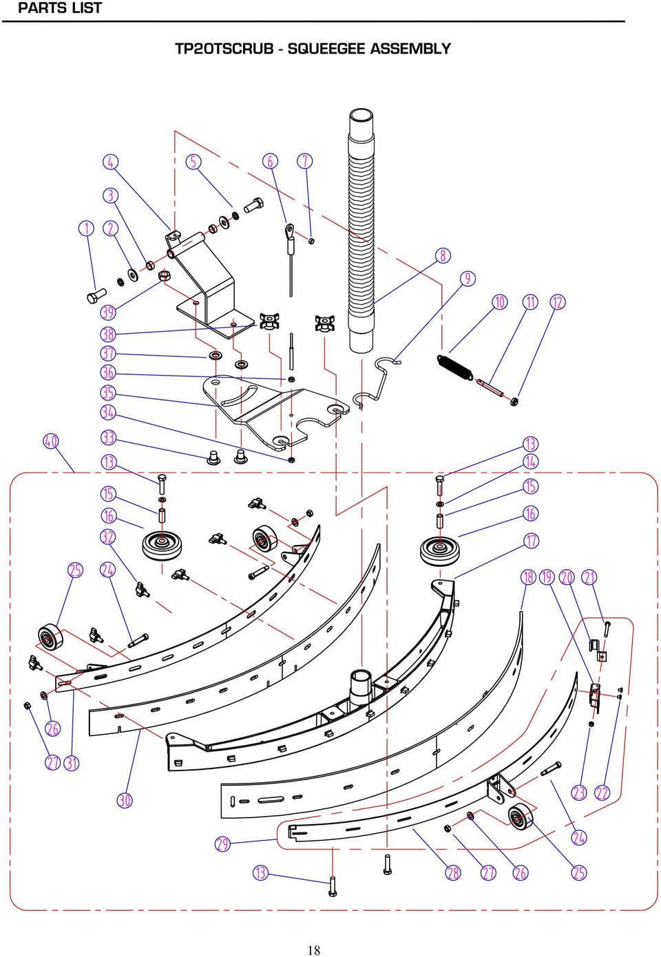
19 DIA PART NUMBER TP20TSCRUB - SQUEEGEE ASSEMBLY DESCRIPTION REQ'D 1 VF14247 SCREW, M12 X VF13538 WASHER, PLAIN, M12 X M26 X VF82016A BUSHING 2 4 VF82330 MOUNT, PIVOT 1 5 VF13541 WASHER, LOCK, M VF82049 CABLE, SQUEEGEE LIFT 1 7 VF82112 BUSHING 1 8 VF81203A HOSE 1 9 VF83150 HOLDER, "U" HOSE 1 10 VF81207 SPRING 1 11 VF82047 SHAFT 1 12 VF13513 NUT, M VF14236 SCREW, M8 X VF13514A WASHER, PLAIN, M8 X M16.5 X VF82055 BUSHING 2 16 VF82013 WHEEL, 3" 2 17 VF82116 HOUSING, SQUEEGEE 1 18 VF82063 BLADE, SQUEEGEE, REAR (PU) 1 VF82119 BLADE, SQUEEGEE, REAR (NEOPRENE ) 1 19 VF81218 LATCH, HOOD 1 20 VF81209 HOOK, REAR SQUEEGEE, BACKUP ADJUSTMENT 1 21 VF14310 SCREW, M5 X VF81208 RIVET, M4 X GT13022 NUT, LOCK, M VF81222 BOLT, SHOULDER, M9.5 X 31.5 X 5/16" 3 25 VF81219 WHEEL, 2" 3 26 VF13535 WASHER, PLAIN, M8 X M20 X VV20203 NUT, LOCKM 5/16" 3 28 VF82120 BACKUP STRIP, SQUEEGEE, REAR 1 29 VF82120A KIT,SQUEEGEE REAR BACKUP STRIP 1 30 VF82062 BLADE, SQUEEGEE, FRONT (PU) 1 VF82117 BLADE, SQUEEGEE, FRONT (NEOPRENE) 1 31 VF82118 BACKUP STRIP, SQUEEGEE, FRONT 1 32 VF82121 KB, M VF82084 BOLT, SHOULDER, M12 X VF13502 NUT, LOCK, M VF82131 BRACKET, SQUEEGEE MOUNT 1 36 VF13521 NUT, M VF13539 WASHER, PLAIN, M12 X M32 X VF81210 KB, M VF14081 NUT, M VF82908A SQUEEGEE ASSEMBLY 1 19
 1 VF82119 BLADE, SQUEEGEE, REAR (NEOPRENE ) 1 19 VF81218 LATCH, HOOD 1 20")
20 20
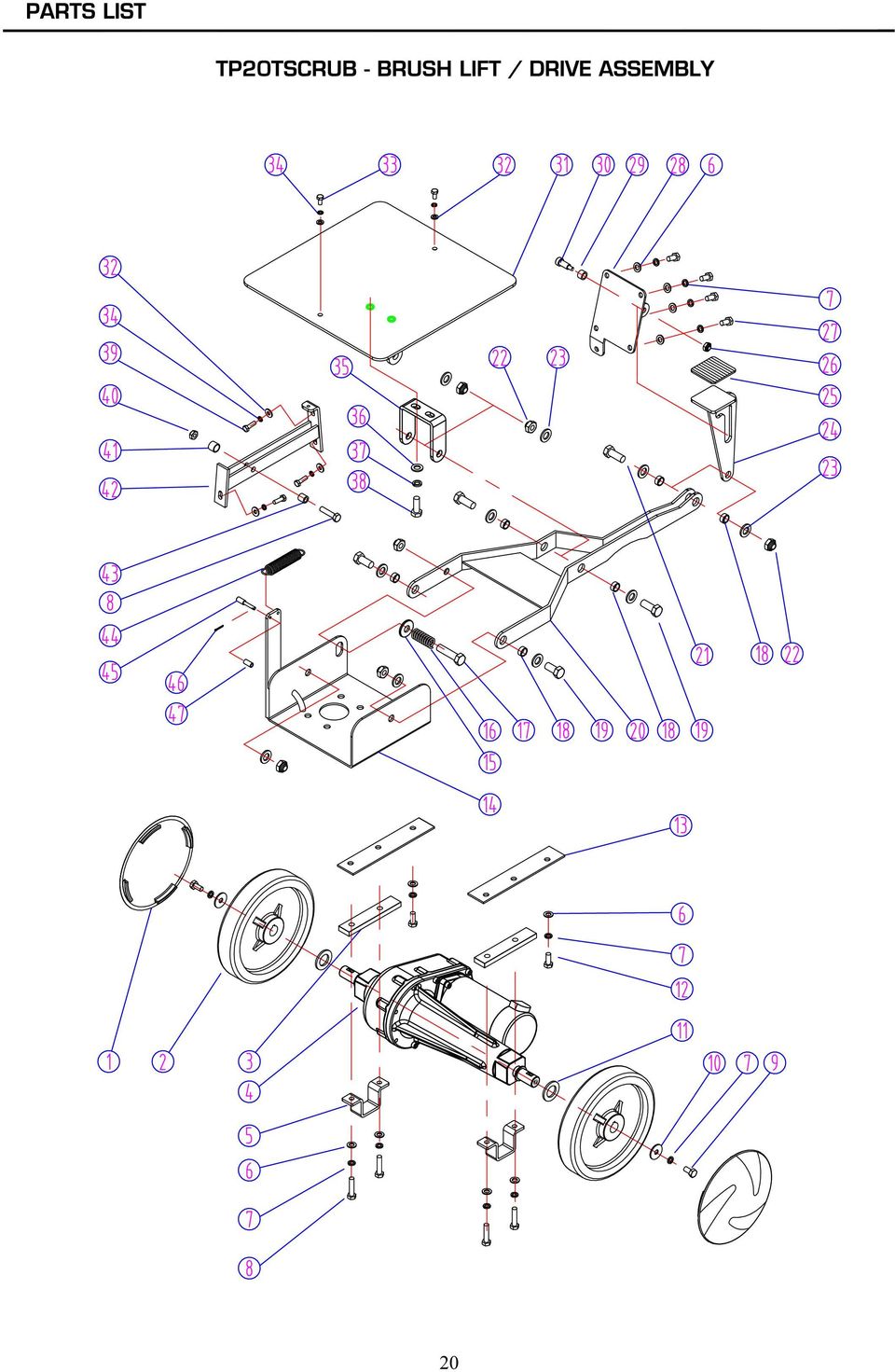
21 DIA PART NUMBER TP20TSCRUB - BRUSH LIFT/DRIVE ASSEMBLY DESCRIPTION REQ'D 1 VF82080TP HUB CAP,TASK-PRO 2 2 VF82006 WHEEL, 8" (Serial# ) 2 VF82208 WHEEL, 8" (Serial#1500+) 2 3 VF82205 SPACER 2 VF82004 TRANSAXLE, 20"(Serial# ) 1 4 VF82200 TRANSAXLE, 20" (Serial#1500+) 1 ZD72000A MOTOR,TRANSAXLE,24VDC (Serial#1500+) 1 VF82207 KEY, 5 X 25 (Serial#1500+) 2 5 VF82204 BRACKET,TRANSAXLE MOUNT 2 6 VF13535 WASHER, PLAIN, M8 X M20 X VF13519 WASHER, LOCK, F VF14236 SCREW, M8 X VF14249 SCREW, M8 X VF13546 WASHER, PLAIN, M8 X M28 X VF82203 WASHER, PLAIN, M20 X M37 X VF14234 SCREW, M8 X VF82206 SPACER 2 14 VF82017 BRACKET, MOTOR 1 15 VF82065 OILITE THRUST WASHER 1 16 VF82064 SPRING 1 17 VF14240 SCREW, M12 X VF82016A BUSHING 6 19 VF14238 SCREW, M12 X VF82016 BRACKET, BRUSH LIFT 1 21 VF14239 SCREW, M12 X VF13501 NUT, LOCK, M VF13538 WASHER, PLAIN, M12 X M22 X VF82020 LATCH, BRUSH LIFT 1 25 VF81111 SPACER, RUBBER 1 26 VV20203 NUT, LOCK, 5/16" 1 27 VV13604 SCREW, M8 X VF82021 BRACKET, BRUSH LIFT, LATCH 1 29 VF82021A BUSHING 1 30 VF82021B BOLT, SHOULDER 1 31 VF82023 MOUNT PLATE, BRUSH LIFT LATCH 1 32 VF13533 WASHER, PLAIN, M6 X M16 X VF13495 SCREW, M6 X VV13607 WASHER, LOCK, M VF82022 BRACKET, ADJUSTMENT 1 36 VF13537 WASHER, PLAIN, M10 X M26 X VF13518 WASHER, LOCK, M VF14123 SCREW, M10 X VF14233 SCREW, M6 X VF13503 NUT, LOCK, M VF82018A BUSHING 1 42 VF82018 ROLLER BRACKET, BRUSH LIFT 1 43 VF82018B BUSHING 1 44 VF81120 SPRING 1 45 VF82158 SHAFT 1 46 VF14096 PIN, M2 X VF82159 BUSHING 1 21
22 22
23 DIA TP20TSCRUB - SOLUTION CONTROL ASSEMBLY PART NUMBER DESCRIPTION REQ'D 1 VF14245 SCREW, M5 X VF82036 SHAFT 1 3 VV13650 SCREW, M4 X VF13532 WASHER, PLAIN, M5 4 5 VV13601 WASHER, LOCK, M5 5 6 VF14230 SCREW, M5 X VF13536 WASHER, PLAIN, M9.8 X M16 X VF82075 NUT, 3/8" 2 9 VF82035 CABLE, SOLEID 1 10 VF82040 HOSE BARB, TEE 1 11 VF82148 CLAMP, 16mm VF82138 TUBING, 75mm 1 13 VF81403 ELBOW, SOLUTION TANK 2 14 VF82134 BRACKET, TUBING 1 15 VF82135 TUBING, 690mm 1 16 VF82133 CLAMP, TUBING 1 17 VF82166 CLAMP,FILTER 2 18 VV20061 SCREW,SELF-TAPPING 4 19 VF82168 FILTER 1 20 VF82041 ELBOW, HOSE BARB 1 21 VF82136 TUBING, 590mm 1 22 VF SOLUTION VALVE, SOLEID, 24VDC 1 23 VF82137 TUBING, 205mm 1 24 VF13495 SCREW, M6 X VV13607 WASHER, LOCK, M VF13533 WASHER, PLAIN, M6 X M16 X VF13502 NUT, LOCK, M VF82034A BRACKET, SOLEID 1 29 VV20509 SCREW,M5X VF81118 CLAMP 3 31 VF13540 WASHER, WAVE, M VF82037 BRACKET, DRAIN HOSE & VALVE 1 33 VF82069 LABEL, VALVE 1 34 VF82074 BUSHING 1 35 VF82038BD KB, VALVE ADJUST 1 23
24 24
25 DIA PART NUMBER TP20TSCRUB - BRUSH SKIRT ASSEMBLY DESCRIPTION REQ'D 1 VF82014 BUMPER 2 2 VA13491 SCREW, M8 X VF13519 WASHER, LOCK, M8 7 4 VF13535 WASHER, PLAIN, M8 X M20 X VF13514A WASHER, PLAIN,M8 X M16.5 X VF82013 WHEEL, 3" 4 7 VF82055 BUSHING 4 8 VF14236 SCREW, M8 X VA13474 SCREW, M5 X VF13550 WASHER, PLAIN, M5 X M25 X VF82068 GRIP, BUMPER 1 12 VF82127 CLAMP, BUMPER 2 13 VA13400 WASHER, PLAIN, M5 X M11 X VV20509 SCREW, M5 X VF82126 CLAMP, BUMPER 1 16 VF82060 COVER 2 17 VF82003 SKIRT 1 18 VF14243 SCREW, M8 X VF82012A CASTER, SWIVEL, 3" 2 20 VF13533 WASHER, PLAIN, M VV13607 WASHER, LOCK, M VF14233 SCREW, M6 X
26 26
27 DIA TP20TSCRUB - BRUSH / PAD DRIVE ASSEMBLY PART NUMBER DESCRIPTION REQ'D 1 ZD45000 BRUSH MOTOR, 24VDC,.75HP 1 2 ZD45407 KEY, 6.35 X VF13545 SCREW, SELF-TAPPING,ST, M5 X VV13601 WASHER, LOCK, M5 4 5 VF83131 CLAMP, BRUSH PLATE 1 6 VF83132 SPRING 1 7 VF83130 PLATE, DRIVE 1 8 VF82058 WASHER 1 9 VV20298 WASHER, LOCK, 5/16" 1 10 VF14241 SCREW, 5/16"-1" 1 11 VF82057 PAD DRIVER, 19" 1 12 VF14225A SCREW, M6 X VF83133 STUD 3 14 VF13502 NUT, LOCK, M VF83118 SPACER 1 16 VF99003A BIG MOUTH 1 17 VA13484 SCREW, SELF-TAPPING,ST, M4 X MF-VF002-4A SCREW, SELF-TAPPING, 1/4"-1" 3 19 VF83130A PLATE, DRIVE, ASSY 1 20 VF83134 STOP, DRIVE RELEASE 1 21 VF14242 SCREW, 3/8" VV13620 WASHER, LOCK, 3/8" 4 23 VF13537 WASHER, PLAIN, M10 X M26 X VF82148 CLAMP, 16mm 1 25 VF82077 TUBING, 55mm 1 27
28 28
FANG 24T, 26T and 28T -EU
 Model: FANG 24T FANG 26T FANG 28T Lista Części Polish Spis Treści Solution tank 3 Recovery tank 5 Brush lift - Drive 7 Brush - Pad Drive 9 Solution Control 11 Brush skirt 13 Control housing 15 Squeegee
20 GALLON WET DRY VACUUM
 20 Gallon Wet & Dry Vacuum 110" Water Lift Vac Motor 24" Front Mount Squeegee Assembly 50' Cord Special Tip Pour Feature Warranty Contractor Tool Kit Includes: Wet p/u Tool, Dry p/u Tool, Crevice Tool,
IMPORTANT SAFETY RULES TO FOLLOW
 WARNING FLOOR & CARPET CLEANER Any piece of equipment can be dangerous if not operated properly. YOU are responsible for the safe operation of this equipment. The operator must carefully read and follow
The Storm 20-Gallon Wet/Dry Vac
 Mercury Floor Machines, Inc. New Equipment Warranty Limited Warranty Mercury Floor Machines, Inc. warrants new equipment against defects in material and workmanship under normal use and service to the
Safety, Operation and Maintenance Manual with Parts List
 Safety, Operation and Maintenance Manual with Parts List 20-Gallon Wet/Dry Vac Important Information and Safety Instructions PLEASE READ BEFORE USE! # 961130020 9/10-Rev 1 20-Gallon Wet/Dray Vac TABLE
CARING FOR YOUR WATER HEATER
 http://waterheatertimer.org/troubleshoot-rheem-tankless-water-heater.html Water Heater Inspections CARING FOR YOUR WATER HEATER Venting System (Direct Vent Only) The venting system should be inspected
123 Industrial Loop Road Paynesville, MN 56362 Phone: 1-800-864-1649 www.master-mfg.com MASTER MANUFACTURING MASTER GARDNER
 123 Industrial Loop Road Paynesville, MN 56362 Phone: 1-800-864-1649 www.master-mfg.com MASTER MANUFACTURING MASTER GARDNER Part Number PCD E3 009B MM Rev 1 Nov. 2010 INTRODUCTION The purpose of this manual
TENNANT T3 SCRUBBER DRYER OPERATOR MANUAL
 TENNANT T3 SCRUBBER DRYER OPERATOR MANUAL Clemas & Co. Unit 5 Ashchurch Business Centre, Alexandra Way, Tewkesbury, Gloucestershire, GL20 8NB. Tel: 01684 850777 Fax: 01684 850707 Email: [email protected]
2510/2550 Dust Control Burnisher
 250/2550 Dust Control Burnisher Operator and Parts Manual TENNANT COMPANY Commercial Products 2875 RANSOM STREET HOLLAND MI 49424 U.S.A. FAX: 800 678 4240 CUSTOMER SERVICE: 800-982 7658 607597 Rev. 0 (2-00)
CDS TROUBLESHOOTING SECTION I. VACUUM. 1.0. Weak vacuum at wand. Gauge reads normal (10hg to 14hg)
") CDS TROUBLESHOOTING SECTION I. VACUUM 1.0. Weak vacuum at wand. Gauge reads normal (10hg to 14hg) 1.1. Clogged hoses or wand tube. Disconnect hoses and carefully check for an obstruction. 1.2. Excessive
CDS TROUBLESHOOTING SECTION I. VACUUM 1.0. Weak vacuum at wand. Gauge reads normal (10hg to 14hg) 1.1. Clogged hoses or wand tube. Disconnect hoses and carefully check for an obstruction. 1.2. Excessive
15GAL STEEL OIL DRAIN WITH 110V PUMP
 15GAL STEEL OIL DRAIN WITH 110V PUMP OWNER S MANUAL WARNING: Read carefully and understand all ASSEMBLY AND OPERATION INSTRUCTIONS before operating. Failure to follow the safety rules and other basic safety
123 Industrial Loop Road Paynesville, MN 56362 Phone: 1-800-864-1649 www.master-mfg.com
 123 Industrial Loop Road Paynesville, MN 56362 Phone: 1-800-864-1649 www.master-mfg.com INTRODUCTION The purpose of this manual is to assist you in the assembly, operation and maintenance of your sprayer
If you accidentally get battery acid on your skin, flush it with lots of water
 RV Battery Savvy To properly maintain and extend the life of your RV batteries you need to have a basic understanding of what a battery is and how it works. Batteries used in RVs are lead acid batteries.
SOLAR PV SYSTEM MAINTENANCE GUIDE
 SOLAR PV SYSTEM MAINTENANCE GUIDE GUYANA HINTERLANDS STAND-ALONE SOLAR PV INSTALLATIONS IMPROVING HEALTH FACILITY INFRASTRUCTURE (IHFI) GUYANA CONTRACT NO. EPP-I-00-03-00008-00, TASK ORDER 07 APRIL 2013
Fleck 4650. Service Manual INSTALLATION AND START-UP PROCEDURE TABLE OF CONTENTS JOB SPECIFICATION SHEET
 Fleck 4650 Service Manual TABLE OF CONTENTS JOB SPECIFICATION SHEET...1 INSTALLATION AND START-UP PROCEDURE...1 CONTROL VALVE DRIVE ASSEMBLY...2 CONTROL DRIVE ASSEMBLY FOR CLOCK...3 BYPASS VALVE ASSEMBLY...4
BACKPACK SPRAYERS. MODEL NOS: KSP16 & KSP20 Part Nos: 3402270 & 3402275 OPERATING & MAINTENANCE INSTRUCTIONS GC04/12
 BACKPACK SPRAYERS MODEL NOS: KSP16 & KSP20 Part Nos: 3402270 & 3402275 OPERATING & MAINTENANCE INSTRUCTIONS GC04/12 INTRODUCTION Thank you for purchasing this CLARKE Sprayer, designed for use only with
Sport Ice Elektro 124
 Sport Ice Elektro 124 Operation Manual 2007/4 V2.1 Introduction The Sport Ice Elektro 124 is an ice resurfacing machine designed to be used on small ice surfaces. The machine has been designed to produce
Polaris 9300 & 9400 Series Robotic Cleaner
 Polaris 9300 & 9400 Series Robotic Cleaner Zodiac Pool Systems, Inc. 1-800-822-7933 www.zodiacpoolsystems.com Regional Extension Instructor ext. Sales Representatives ext. ext. Service Manager ext. ext.
OPL BASIC. Dosing System for Professional Laundry machines. Contents
 OPL BASIC Dosing System for Professional Laundry machines Contents 1 Getting Started. Page 2 2 Installation. Page 4 3 Set Up & Operation. Page 8 4 Maintenance & Accessories. Page 10 5 Troubleshooting Page
Range Road RR Series Semi-Automatic Firewood Processor. Crated Unit Assembly Manual
 Range Road RR Series Semi-Automatic Firewood Processor Crated Unit Assembly Manual 1 1) Undo 8-18mm x 19mm Nuts and bolts, 2 on each leg of top frame 2) Lift top of Metal crate off and move out of work
Installation Instructions 4508 4508S
 SYMPHONY Spread Lavatory Faucet with Speed Connect Drain Congratulations on purchasing your American Standard faucet with Speed Connect drain, a feature found only on American Standard faucets. Speed Connect
National- Spencer Inc.
 9-27-2010 National- Spencer Inc. 19.2V HEAVY DUTY GREASE GUN PRODUCT SPECIFICATION Charger Input Power 110 VAC Battery Output Power 19.2V Battery Capacity 1500 MAH Battery Pack Charge Time 1 Hour Maximum
Battery Backup Sump Pump System
 Battery Backup Sump Pump System Instruction Manual Battery Operated SUMP TEST Push to Test System RESET Push to Silence Pump Alarm Warning BATTERY FUSE WATER POWER What to do Terminals corroded or battery
English. Symbols used to mark instructions...3. Congratulations...5 Getting the best results...5. Warnings...6 Operating Procedure...
 2 Contents Components Attachments Guidance Installation Operation Maintenance Service Technical Troubleshooting Symbols used to mark instructions...3 Included Attachments...4 Congratulations...5 Getting
VE17 DSP. Model: VE-17DS. Lista Części Polish
 Model: VE-17DS Lista Części Polish Spis Treści Handle 3 Base 5 Wiring - Wear and Tear parts 7 DF100-A Foam Generator art no. 50000055 9 Handle VE02 3 Handle VE02 4 Poz Numer katalogowy Iloś Opis 1 VF40104EU
DANGER DANGER. General Information. Safety Is Your Responsibility. Ordering Parts. Contact Information
 Safety Safety Is Your Responsibility DANGER To avoid personal injury or death, carefully read and understand all instructions pertaining to the Anthony Liftgates product. Do not attempt to install, operate,
Air Vantage 500 Kubota
 Illustration of Sub Assemblies Illustration of Sub Assemblies Illustration of Sub Assemblies Illustration of Sub Assemblies P-625 P-625 RETURN TO MAIN INDEX PARTS LIST FOR Air Vantage 500 Kubota P-625-A
Rear wheel brakes, servicing. Стр. 1 из 45. Note:
 Volkswagen Touareg - Rear wheel brakes, servicing Стр. 1 из 45 46-2 Rear wheel brakes, servicing Rear brakes, FN 44 brake caliper, servicing Note: After replacing brake pads, depress brake pedal firmly
Back Pack Sprayer. Operator's Manual MODELS MS - 40 MS - 50
 Back Pack Sprayer Operator's Manual MODELS MS - 40 MS - 50 WARNING DANGER Read rules for safe operation and all instructions carefully. ECHO provides this Operator's Manual which must be read and understood
accidents which arise due to nonobservance and the safety information herein.
 20 GALLON COMPRESSOR Model: 7342 CALIFORNIA PROPOSITION 65 WARNING: You can create dust when you cut, sand, drill or grind materials such as wood, paint, metal, concrete, cement, or other masonry. This
ZAPPY 3 OWNER S MANUAL. Read this manual completely before riding your Electric ZAPPY 3.
 ZAPPY 3 OWNER S MANUAL Read this manual completely before riding your Electric ZAPPY 3. TECHNICAL INFORMATION Model No. : ZAPPY 3 Product size Type of motor Motor power Battery type Battery Charger Charging
VE13P-EU. Model: VE13. Lista Części Polish
 Model: VE13 Lista Części Polish Spis Treści Handle 3 Base 5 Wiring - Wear and Tear parts 7 DF100-A Foam Generator art no. 50000055 9 RECOMMENDED SPARE PARTS 13 Handle VE02 3 Handle VE02 4 Poz Numer katalogowy
ROTARY TUMBLER INSTRUCTIONS AND PARTS LIST
 ROTARY TUMBLER INSTRUCTIONS AND PARTS LIST Model 3-1.5B Model 45C Model 33B LORTONE 12130 Cyrus Way Mukilteo, WA 98275 (425) 493-1600 SETTING UP YOUR MACHINE For 45C Unit Only (33B & 3-1.5B already assembled)
BUILT-IN DISHWASHER INSTALLATION INSTRUCTIONS
 BUILT-IN DISHWASHER INSTALLATION INSTRUCTIONS PLEASE READ COMPLETE INSTRUCTIONS BEFORE YOU BEGIN LEAVE INSTALLATION INSTRUCTIONS AND USER'S GUIDE WITH OWNER ALL ELECTRIC WIRING AND PLUMBING MUST BE DONE
PAINT SPRAY GUN WASHER
 PAINT SPRAY GUN WASHER 94996 ASSEMBLY AND OPERATING INSTRUCTIONS Visit our website at: http://www.harborfreight.com Read this material before using this product. Failure to do so can result in serious
Volkswagen Jetta, Golf, GTI 1999, 2000 Brake System 46 Brakes - Mechanical Components (Page GR-46)
") 46 Brakes - Mechanical Components (Page GR-46) Front brakes Brake pads, removing and installing Brake pads, removing and installing FN 3 brake caliper, servicing FS III brake caliper, servicing Rear wheel
46 Brakes - Mechanical Components (Page GR-46) Front brakes Brake pads, removing and installing Brake pads, removing and installing FN 3 brake caliper, servicing FS III brake caliper, servicing Rear wheel
TERMINATION EQUIPMENT INSTRUCTION MANUAL TELE-PIERCE P/N 356-246
 TERMINATION EQUIPMENT INSTRUCTION MANUAL TELE-PIERCE P/N 356-246 OPERATION AND SERVICE INSTRUCTIONS AMPHENOL 157 SERIES TELE-PIERCE MULTI-WIRE TERMINATION TOOL 356-246 AMPHENOL TERMINATION SYSTEMS 1830
HYDRAULIC TABLE CART 500-LB.
 HYDRAULIC TABLE CART 500-LB. OWNER S MANUAL WARNING: Read carefully and understand all MACHINE ADJUSTMENT AND OPERATION INSTRUCTIONS before operating. Failure to follow the safety rules and other basic
Model 854/856. Operating and Assembly Manual. Palmor Products Inc. 5225 Serum Plant Road Thorntown, IN 46071
 Model 854/856 Operating and Assembly Manual Palmor Products Inc. 55 Serum Plant Road Thorntown, IN 46071 3/31/2015 SAFETY RULES Remember, any power equipment can cause injury if operated improperly or
Voltmaster Trash Pumps Model TSP2, TSP3 and TSP4
 Model TSP2, TSP3 and TSP4 Owner s Manual July 2010 Table of Contents 1 Introduction...................................................... 1 1.1 Read before using..............................................
Solstice/Sky Water Pump Replacement
 Solstice/Sky Water Pump Replacement The water pump on the Solstice/Sky is starting to need replacement on some vehicles. This guide will help in replacing the water pump while the engine is still in the
Overview PARTS LIST. B. Lever mounting base C. Flush handle assembly D. Grey/Blue float stop E. Grey float (Full Flush) F. Flush valve washer
 F. Flush valve washer") Overview READ ENTIRE INSTRUCTIONS BEFORE STARTING INSTALLATION PARTS LIST A. Flush valve B. Lever mounting base C. Flush handle assembly D. Grey/Blue float stop E. Grey float (Full Flush) F. Flush valve
Overview READ ENTIRE INSTRUCTIONS BEFORE STARTING INSTALLATION PARTS LIST A. Flush valve B. Lever mounting base C. Flush handle assembly D. Grey/Blue float stop E. Grey float (Full Flush) F. Flush valve
FASCINATION 700 HVLP TANNING PRO SYSTEM USER MANUAL
 FASCINATION 700 HVLP TANNING PRO SYSTEM USER MANUAL Congratulations on choosing the Fascination 700 HVLP Tanning Pro System! Your system includes the following items: 1 Fascination 700 HVLP Tanning Pro
Agri-Fab OWNERS MANUAL. Model No. 45-02931 25 GALLON "PRO" TOW SPRAYER
 Agri-Fab OWNERS MANUAL Model No. 45-02931 CAUTION: Read Rules for Safe Operation and Instructions Carefully Assembly Operation Maintenance Repair Parts 25 GALLON "PRO" TOW SPRAYER the fastest way to purchase
Hot, Warm and Cold Mineral Water Cooler [Models Cool18, Cool25, Cool36, Cool50, Cool75, Cool100]
![Hot, Warm and Cold Mineral Water Cooler [Models Cool18, Cool25, Cool36, Cool50, Cool75, Cool100]](/thumbs/26/7741864.jpg "Hot, Warm and Cold Mineral Water Cooler [Models Cool18, Cool25, Cool36, Cool50, Cool75, Cool100]") Hot, Warm and Cold Mineral Water Cooler [Models Cool18, Cool25, Cool36, Cool50, Cool75, Cool100] PLEASE READ BEFORE INSTALLATION TO PREVENT DAMAGE TO THE COOLER HOT WATER TANK STEAM EXAUST VENT (CAUTION!)
Hot, Warm and Cold Mineral Water Cooler [Models Cool18, Cool25, Cool36, Cool50, Cool75, Cool100] PLEASE READ BEFORE INSTALLATION TO PREVENT DAMAGE TO THE COOLER HOT WATER TANK STEAM EXAUST VENT (CAUTION!)
Cleaning Instructions for Burner, Pilot Assembly, and Emitter Screen Series: 220000-450000
 Cleaning Instructions for Burner, Pilot Assembly, and Emitter Screen Series: 220000-450000 10 mm open end wrench 12 mm open end wrench 9/16 open end wrench 5/8 open end wrench 11/16 open end wrench 9/16
HYDRAULIC LIFT TABLE CART 2200-LB.
 HYDRAULIC LIFT TABLE CART 2200-LB. OWNER S MANUAL WARNING: Read carefully and understand all MACHINE ADJUSTMENT AND OPERATION INSTRUCTIONS before operating. Failure to follow the safety rules and other
Front brakes (FN- 3), servicing
, servicing") j a t Front brakes (FN- 3), servicing 46-1 Front brakes, servicing Note: Install complete repair kit. After replacing brake pads and before moving vehicle, depress brake pedal several times firmly to properly
j a t Front brakes (FN- 3), servicing 46-1 Front brakes, servicing Note: Install complete repair kit. After replacing brake pads and before moving vehicle, depress brake pedal several times firmly to properly
INSTRUCTIONS AND PARTS LIST FOR MODEL 70H & 75H HAND-OPERATED HYDRAULIC PRESS
 INSTRUCTIONS AND PARTS LIST FOR MODEL 70H & 75H HAND-OPERATED HYDRAULIC PRESS SETTING UP THE PRESS FOR OPERATION For shipping convenience, the gauge, pump handle, hoist crank, screw nose and base angles
OWNERS MANUAL. Model No. 45-0292 15 GALLON "PRO" TOW SPRAYER
 OWNERS MANUAL Model No. 45-0292 CAUTION: Read Rules for Safe Operation and Instructions Carefully Assembly Operation Maintenance Repair Parts 15 GALLON "PRO" TOW SPRAYER PRINTED IN USA FORM NO. 47628 (REV.
OWNER S MANUAL Table Tennis Table Patent Pending
 OWNER S MANUAL Table Tennis Table Patent Pending Be sure to write your model number and serial number here for future reference. You can find these numbers printed on the bottom of the table. MODEL # T8179
Model MS-41BP 4G/ 15L. WARNING Carefully Read These Instructions Before Use 013529 R0514
 Backpack Sprayer Use and Care Manual Model MS-41BP 4G/ 15L WARNING Carefully Read These Instructions Before Use 013529 R0514 WARNING WARNING: Improper use or failure to follow instructions can result in
5800 Temperature Sensor Cable Assembly
 5800 Temperature Sensor Cable Assembly Removal and Replacement Instruction Sheet #60-4702-070 Revision D, January 14, 2013 Overview The 5800 has two refrigeration temperature sensors, one attached to the
VOYAGER 570G. 744A Sprayer Control
 VOYAGER 570G 744A Sprayer Control U S E R M A N U A L U S E R M A N U A L Table of Contents CHAPTER 1 - INTRODUCTION...1 SYSTEM CONFIGURATIONS...1 KIT CONTENTS...3 CONTROL HOUSING ASSEMBLY...5 CHAPTER
Rules for Safe Operation
 Rules for Safe Operation Important: Do not attempt to operate the CleanStation until you have read and understand all of the instructions in this manual. Failure to do so may result in injury. The machine
MBSAW. Meat Cutting Band Saw With Meat Grinder Assembly & Operating Instructions
 06/2011 MBSAW Meat Cutting Band Saw With Meat Grinder Assembly & Operating Instructions READ ALL INSTRUCTIONS AND WARNINGS BEFORE USING THIS PRODUCT. This manual provides important information on proper
13. REAR WHEEL/BRAKE/SUSPENSION
 13. REAR WHEEL/BRAKE/SUSPENSION 13 3.5~4.5kg-m 8.0~10.0kg-m 0.8~1.2kg-m 3.0~4.0kg-m 2.4~3.0kg-m 3.5~4.5kg-m 6.0~8.0kg-m 13-0 13. REAR WHEEL/BRAKE/SUSPENSION 13 REAR WHEEL/BRAKE/SUSPENSION SERVICE INFORMATION...
OWNER S MANUAL. Model AE150/AE300/AE500 1.5AMP MULTI-USE SMART BATTERY CHARGER READ ENTIRE MANUAL BEFORE USING THIS PRODUCT
 Model AE150/AE300/AE500 MULTI-USE SMART BATTERY CHARGER Certified by Californiia BCS Regulations AE300E AE500E 5AMP MULTI-USE AUTOMOTIVE BATTERY CHARGER 3AMP MULTI-USE SMART BATTERY CHARGER AE500E 5AMP
HYLA NST Cleaning System
 Owner s Manual HYLA NST Cleaning System The HYLA NST Cleaning System aspirates and cleans the air through a waterbased filtration process. The system is intended for household use only. Applications: Usual
SERVICE PARTS LIST PAGE 1 OF 6 BASE ASSEMBLY SPECIFY CATALOG NO. AND SERIAL NO. WHEN ORDERING PARTS 12" DUAL BEVEL COMPOUND MITER SAW B27A
 PAGE 1 OF 6 BASE ASSEMBLY 00 0 EXAMPLE: Component Parts (Small #) Are Included When Ordering The Assembly (Large #). SPECIFY CATALOG NO. AND NO. WHEN ORDERING PARTS 1 02-80-0050 Thrust Bearing (1) 2 05-80-0510
- 2 - IMPORTANT SAFETY REMINDERS
 USER MANUAL IMPORTANT SAFETY REMINDERS This appliance should only be used for domestic cleaning, as described in this user guide. Please ensure that this guide is fully understood before operating the
Operating Instructions
 Operating Instructions Series L 000 Cord Reels Model Numbers: L 000 L 0 0 L 0 B L 0 X L 00 L A X L 0 L 0 0 L 00 L 0 L 0 B L 0 0 X L 00 L 0 A L 0 X IMPORTANT Read this manual carefully before installing,
OASIS-PLUS 120V READ ALL INSTRUCTIONS BEFORE OPERATING READ ALL INSTRUCTIONS BEFORE OPERATING OZONE IS A POWERFUL OXIDIZER AND MUST BE USED WITH CARE
 OASIS-PLUS 120V INFORMATION & OPERATING INSTRUCTIONS READ ALL INSTRUCTIONS BEFORE OPERATING READ ALL INSTRUCTIONS BEFORE OPERATING OZONE IS A POWERFUL OXIDIZER AND MUST BE USED WITH CARE 56041852 WARNING:
ELECTRIC BICYCLE OWNER S MANUAL
 ELECTRIC BICYCLE OWNER S MANUAL For Owners of EG Bali 500EX and EG Milan 500EX Electric Bicycle Table of Contents Descriptions: Page Installation Instructions 2 How to install the bicycle out of the box
K-39/K-39B. Drain Cleaning Machine. Ridge Tool Company/Elyria, Ohio, U.S.A.
 K-/K-B A- AUTOFEED Cable Chuck Pan Head Screw # - () Chuck Adapter Nose Piece Spiral Ring () Hand Grip Sleeve Clamp Springs () Spacer Clips () Gasket Drum Front Drum Liner Screw # - x () Drum Back Power
356 CHECKLIST ELECTRICAL: CHASSIS:
 356 CHECKLIST ELECTRICAL: Headlights hi/lo beam Taillights Running lights Turn signals Brake lights License light(s) Fog lights Reverse light Horn Dome lights Dash lights Temp guage Tank level guage Tachometer
SHOT BLAST CABINET MODEL NO: CSB20B
 SHOT BLAST CABINET MODEL NO: CSB20B PART NO: 7640110 USER INSTRUCTIONS GC0216 INTRODUCTION Thank you for purchasing this CLARKE Shot Blast Cabinet which is designed for professional workshop use. Before
Volkswagen Jetta, Golf, GTI 1999, 2000 2.8 Liter VR6 2V Engine Mechanical, Engine Code(s): AFP 17 Engine-Lubrication (Page GR-17)
: AFP 17 Engine-Lubrication (Page GR-17)") 17 Engine-Lubrication (Page GR-17) Lubrication system components, removing and installing Oil filter housing, disassembling and assembling Oil pan, removing and installing Oil pressure and oil pressure
17 Engine-Lubrication (Page GR-17) Lubrication system components, removing and installing Oil filter housing, disassembling and assembling Oil pan, removing and installing Oil pressure and oil pressure
PRODUCT MANUAL - M090
 PRODUCT MANUAL - M090 MODEL 203/266 ELECTRIC CAN OPENER 1 SAFETY CAUTION: SEVERED CAN LIDS HAVE CUTTING EDGES. USE OF A PROTECTIVE GLOVE OR TONGS IS ADVISED WHEN HANDLING LIDS. WARNING To avoid risk of
ALTRA 400 Operator Manual. Planographs and Wiring Diagrams
 Planographs and Wiring Diagrams 16 Altra 400 Final Assembly All Altras w/head # Part # Description Specific Use (if any) 1 60323A Tank Assy, Altra 400 115 Volt model 60358A Tank Assy, Altra 400 SP 230
DC REFRIGERATORS 12/24 VOLTS INSTALLATION AND OWNER S MANUAL
 DC REFRIGERATORS 12/24 VOLTS INSTALLATION AND OWNER S MANUAL Service Information If service or parts are required, contact the nearest Norcold Service Center. To find an authorized Norcold Service Center
Not required for most applications Not required for most applications High pressure (12-803 provided) High pressure (12-803 provided)
 High pressure (12-803 provided)") ELECTRIC FUEL PUMPS P/N 12-801-1, 712-801-1, 12-802-1, 712-802-1, 12-815-1, & 712-815-1 FUEL PRESSURE REGULATORS P/N 12-803, 12-501, 12-804, 12-500, & 15812NOS Installation Instructions THESE INSTRUCTIONS
ELECTRIC FUEL PUMPS P/N 12-801-1, 712-801-1, 12-802-1, 712-802-1, 12-815-1, & 712-815-1 FUEL PRESSURE REGULATORS P/N 12-803, 12-501, 12-804, 12-500, & 15812NOS Installation Instructions THESE INSTRUCTIONS
San josé OWNER S MANUAL
 San josé OWNER S MANUAL Assembling & operating manual San josé 30 mbar - PORTABLE GAS BARBECUE 1. 2. 3. Improper installation, adjustment, alteration, service or maintenance can injury or property damage.
SIBIR MANUAL V110 KE. English page 5 RKE - 1D 822 70 66-02
 SIBIR MANUAL RKE - 1D V110 KE English page 5 822 70 66-02 2 1 A. Flue tube E. Adapter I. Thermostat B. Flue baffle F. Burner base J. Lever arm C. Control knob G. Lamp glass D. Fuel gauge H. Lamp glass
MG1532 & MG2032 MIXER-GRINDERS
 MIXER-GRINDER MG1532 & MG2032 MIXER-GRINDERS MODEL MG1532 ML-134099 7.5 HP Grind Motor + 1 HP Mix Motor MG1532 ML-134103 5 HP Grind Motor + 1 HP Mix Motor MG1532 ML-134100 7.5 HP Grind Motor + 1 HP Mix
ELECTRIC KNIFE SHARPENER
 PRODUCT MANUAL- M109 MODEL 401 ELECTRIC KNIFE SHARPENER Please read thoroughly before operation and keep for future reference Model 401 Knife Sharpener Specifications Model No. #401 Power Requirements
DTM04 TANK MONITOR DTM08 TANK MONITOR Dtm12 TANK MONITOR. Installation and Operation Manual
 DTM04 TANK MONITOR DTM08 TANK MONITOR Dtm12 TANK MONITOR Installation and Operation Manual 1 ENGLISH Safety Instructions 2 Features 2-3 Specifications 3 Installation 4-5 Wiring Diagrams 6-7 Warranty 8
Volkswagen Jetta, Golf, GTI 1999, 2000 Brake System 47 Brakes - Hydraulic Components (Page GR-47)
") 47 Brakes - Hydraulic Components (Page GR-47) FS III front brake calipers, servicing Front brake caliper piston, removing and installing FN 3 front brake calipers, servicing Front caliper piston, removing
47 Brakes - Hydraulic Components (Page GR-47) FS III front brake calipers, servicing Front brake caliper piston, removing and installing FN 3 front brake calipers, servicing Front caliper piston, removing
USER INSTRUCTIONS FOR 10 LITRE PORTABLE DEHUMIDIFIER MODEL NO. DHMD102
 USER INSTRUCTIONS FOR 10 LITRE PORTABLE DEHUMIDIFIER MODEL NO. DHMD102 THANK YOU FOR CHOOSING YOUR NEW DEHUMIDIFIER. BEFORE USING THE UNIT READ THESE INSTRUCTIONS FULLY AND RETAIN THEM FOR FUTURE REFERENCE
ClearView 100. Instruction Manual
 ClearView 100 Instruction Manual Important Safeguards This appliance is not intended for use by children or infirm persons without supervision. Young children should be supervised to ensure that they do
12 Volt 30 Amp Digital Solar Charge Controller
 12 Volt 30 Amp Digital Solar Charge Controller User s Manual WARNING Read carefully and understand all INSTRUCTIONS before operating. Failure to follow the safety rules and other basic safety precautions
POWER TO GET THE JOB DONE
 52720 1.5 AMP SLOW 12 VOLT BATTERY CHARGER OWNER S MANUAL KEEPS BATTERIES FULLY CHARGED IN STORAGE Automatic over-charging protection Short circuit protection Reverse hook-up protection Overheat protection
SBC90. Abrasive Blast Cabinet Assembly & Operating Instructions
 SBC90 Abrasive Blast Cabinet Assembly & Operating Instructions READ ALL INSTRUCTIONS AND WARNINGS BEFORE USING THIS PRODUCT. SAVE THESE INSTRUCTIONS FOR FUTURE REFERENCE. This manual provides important
Section M POWER LIFTS
 Section M POWER LIFTS December 2009 1M Index 1. 53-520244-000 Poly V Idler Assembly 2. 53-520205-000 N.A. Mounting Bracket 3. 53-520212-000 Cable Assembly 4. 53-600149-000 Wire Harness Assembly 5. 53-860322-010
Micro Cart User's Guide
 Micro Cart User's Guide To take full advantage of the ergonomic features of your new Sun Mountain Micro Cart, please read the following information. SUN MOUNTAIN 1 Your Micro Cart has several innovative
Cleaning Instructions, Pilot Replacement and Valve Change. Model No.: 233010 Natural Gas
 Cleaning Instructions, Pilot Replacement and Valve Change Model No.: 233010 Natural Gas 8mm open-end wrench 9mm open-end wrench 10mm open-end wrench 12mm open-end wrench 13mm open-end wrench Phillips screw
CHARGING SYSTEMS INTERNATIONAL
 CHARGING SYSTEMS INTERNATIONAL INSTALLATION AND OPERATING INSTRUCTIONS FOR THE FOLLOWING BATTERY CHARGING SYSTEMS: MODELS MAX AMPS/BANK NO. OF BANKS BATTERY SYSTEM PRO XL 6 1 12 DUAL PRO XL 6 2 12/24 PRO
Carpet Washer. vax.co.uk VRS5W. Vax Careline: (UK) 0844 412 8455 (ROI) 1-800 928 308. Vax model number: Version 1.0
 0844 412 8455 (ROI) 1-800 928 308. Vax model number: Version 1.0") VRS5W Powermax User Guide V1.0.qxd:V1.0 23/7/10 15:35 Page 1 Vax Careline: (UK) 0844 412 8455 (ROI) 1-800 928 308 Carpet Washer Vax model number: VRS5W instruction manual Version 1.0 Please read carefully
VRS5W Powermax User Guide V1.0.qxd:V1.0 23/7/10 15:35 Page 1 Vax Careline: (UK) 0844 412 8455 (ROI) 1-800 928 308 Carpet Washer Vax model number: VRS5W instruction manual Version 1.0 Please read carefully
MODEL T200-F18 MODEL T125-F18 Finish Nailers
 P MODEL T200-F18 MODEL T125-F18 Finish Nailers IMPORTANT! DO NOT DESTROY It is the customer s responsibility to have all operators and service personnel read and understand this manual. OPERATING MANUAL
FloorMATE with SpinScrub Brushes The Hard Floor Cleaner
 FloorMATE with SpinScrub Brushes The Hard Floor Cleaner Owner s Manual English pp. 1-13 Español pàg. 15-22 Français p. 24-31 Thank you for selecting a HOOVER product. This cleaner inspected and packaged
Multi-Pitch Pitching Machine USER MANUAL
 Multi-Pitch Pitching Machine USER MANUAL TABLE OF CONTENTS Thank you for purchasing the Cimarron Multi-Pitch Pitching Machine. The Cimarron Multi-Pitch Pitching Machine is a high performance pitching machine
PUMP MAINTENANCE SCHEDULE AND CHECKLISTS
 PUMP MAINTENANCE SCHEDULE AND CHECKLISTS Providing a maintenance schedule defined specifically by run hours or yardage pumped serves only as a general guideline given the large amount of variables a unit
SC351. Model: SC351 NIL. Part List US-English
 Model: NIL Part List US-English Table of Contents GENERAL VIEW 3 COVER AND TANKS 5 FRAME SYST 7 HANDLE SUPPORT SYST 9 HANDLE SYST 12 MOTOR AND DECK SYST 15 BRUSH DECK SYST 17 ACCESSORIES 19 WIRING DIAGRAM
MODEL #12006. Introduction
 THE ORIGINAL PECO POWER SPRAYER PECO OWNER S MANUAL MODEL #12006 (Q0080) Revised: 1/8/2014 PECO POWER SPRAYER MODEL #12006 TABLE OF CONTENTS SECTION PAGE SECTION PAGE INTRODUCTION - - - - - - - - - - -
ROTARY TUMBLER INSTRUCTIONS AND PARTS LIST
 ROTARY TUMBLER INSTRUCTIONS AND PARTS LIST Model QT66 Model QT12 Model QT6 LORTONE 12130 Cyrus Way Mukilteo, WA 98275 (425) 493-1600 SETTING UP YOUR MACHINE Install The Barrel Guide: Using the machine
POWER LOCK KIT GENERAL INSTALLATION -J04427 REV. 2007-12-04. Kit Number. Models. Additional Parts Required. Kit Contents
 -J0 REV. 00--0 POWER LOCK KIT GENERAL Kit Number -0, 0-0 Models For model fitment information, please see the P&A Retail Catalog or the Parts and Accessories section of www.harleydavidson.com (English
CutMaster 82. 6.04 Major External Replacement Parts
 CutMaster 8 6.0 Major External Replacement Parts Item # Qty Description Catalog # Cover with labels 9-08 Base Enclosure Assembly 9-08 Tube, roll handle 9-0 Front Panel 9-07 Rear Panel 9-00 Art # A-080
JANUS INTERNATIONAL CORPORATION INSTALLATION INSTRUCTIONS Pantheon Mini Operator
 JANUS INTERNATIONAL CORPORATION INSTALLATION INSTRUCTIONS Pantheon Mini Operator The Janus Pantheon mini operator does not typically require the provision of any additional site requirements other than
USER S, MAINTENANCE and SERVICE INFORMATION MANUAL
 CONTENTS SAFETY INFORMATION................ 2 FOR YOUR SAFETY....................... 2 SYSTEM OPERATION.................. 2 THERMOSTATS........................... 2 INTERMITTENT IGNITION DEVICE...........