(12) United States Patent Hedman et a].
|
|
|
- Melinda Miles
- 7 years ago
- Views:
Transcription
1 US B2 (12) United States Patent Hedman et a]. (10) Patent N0.: (45) Date of Patent: Jan. 3, 2012 (54) (75) (73) (*) (21) (22) (86) (87) (65) (51) (52) (58) GEAR TRANSMISSION WITH REDUCED TRANSMISSION WALL HOUSING DEFLECTION Inventors: Anders Hedman, Marstrand (SE); Lars Zettergren, Myggenas (SE) Assignee: Volvo Lastvagnar AB, Goteborg (SE) Notice: Subject to any disclaimer, the term of this patent is extended or adjusted under 35 U.S.C. 154(b) by 383 days. Appl. No.: 12/297,456 PCT Filed: May 17, 2006 PCT No.: PCT/SE2006/ (2), (4) Date: Oct. 17, 2008 PCT Pub. No.: WO2007/ PCT Pub. Date: Nov. 22, 2007 Prior Publication Data US 2009/ A1 Apr. 23, 2009 Int. Cl. F16H 57/02 ( ) US. Cl /606 R Field of Classi?cation Search /412 R, 74/413, 431, 606 R See application?le for complete search history. (56) References Cited U.S. PATENT DOCUMENTS 1,971,968 A * 8/1934 Schmitter /421A 3,154,963 A * 11/1964 Caleyet a /421R 3,430,523 A 3/1969 Merritt 5,188,572 A 2/1993 Yamaguchiet a1. 5,433,672 A 7/1995 Tanaka et a1. 5,787,766 A * 8/1998 Blach /665G 6,601,467 B1* 8/2003 Futterer /421 A FOREIGN PATENT DOCUMENTS EP B1 10/1992 wo A1 12/2005 OTHER PUBLICATIONS International Search Report for corresponding International Appli cation PCT/SE2006/ International Preliminary Report on Patentability for corresponding International Application PCT/SE2006/ * cited by examiner Primary Examiner * Vicky Johnson (74) Attorney, Agent, or Firm * WRB-IP LLP (57) ABSTRACT A gear transmission is provided including at least a?rst and a second shaft With substantially?xed and substantially paral lel axes of rotation, a transmission housing With a?rst and a second Wall that extends perpendicular to the axes of rotation, and a plurality of gearwheels that are rotationally?xed or rotationally?xable to the shafts. The shafts include at least one input shaft and at least one output shaft, the shafts being suspended by bearings that are seated in the?rst and second Walls. The?rst Wall is connected to the second Wall With at least one rod in order to reduce de?ections in operation of the?rst and second Walls. 12 Claims, 3 Drawing Sheets 51% 551a lb b
, (4) Date: Oct. 17, 2008 PCT Pub. No.: WO2007/133131 PCT Pub. Date: Nov. 22, 2007 Prior Publication Data US 2009/0100966 A1 Apr. 23, 2009 Int. Cl. F16H 57/02 (2006.01) US. Cl...... 74/606 R Field of Classi?")
2 US. Patent Jan. 3, 2012 Sheet \ X 104 {\\\\\\\& \ H _. / % g (pr10r art) r 230 _. _. _. _ ~ _. -_._ 331t 2 4, n r 3311: - I/ Flg 2 F1. 3 (prior (P ar g
 231 331 233. 2300 27 232 230r 230 _. _. _. _ ~ _. -_.")
3
4 US. Patent Jan. 3, 2012 Sheet 3 of3 702b 702a r701 7 Q \ 7511; b \ 706 Fig w \ \PE A zv/j 4///////////////////////////////////%

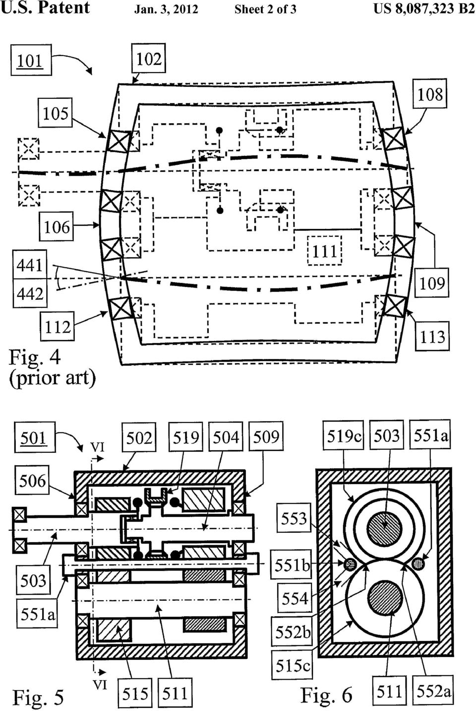
5 1 GEAR TRANSMISSION WITH REDUCED TRANSMISSION WALL HOUSING DEFLECTION BACKGROUND AND SUMMARY The present invention relates to gear transmissions, and more particularly to a system for decreased de?ection of transmission housing Walls that are subjected to bearing loads. Fix-axes gear transmissions are used in many?elds of technology, for instance in vehicles in manually shifted or automated form. They comprise a number of gearwheels that are located on a number of shafts. The shafts are supported by bearings that are seated in a transmission housing. The rota tional axes of the shafts are thereby substantially?xed, hence the designation?x-axes gear transmissions. When torque is transferred from one gearwheel to another, signi?cant gear mesh forces arise. These gear mesh forces Will create reaction forces in the bearings. Thereby, in operation the Walls of the transmission housings Will be subjected to forces that Will tend to de?ect the Walls. For proper function and life of the gearwheels and bearings, it is important that these de?ections are limited. In order to reduce Weight, there is a trend towards using light alloys rather than iron based alloys for the transmission housings. Due to lower inherent stiffness of conventional light alloys, the de?ections of the housing Walls Will increase. Furthermore, cost-e?icient casting methods for light alloys do not permit as large Wall thickness as is common in cast iron housings. That Will further increase the de?ections in light alloy housings. Finally, the signi?cantly larger thermal expansion of light alloys compared to steel Will cause increased axial clearance in the bearings at operating tem perature, Which Will give reduced bearing life. There are some known Ways to reduce the increased de?ec tions of the Walls of transmission housings made of light alloys. Firstly, reinforcing ribs Will increase the stiffness of the Walls While maintaining a small Wall thickness. This can be seen in DE-l and DE-l03l632l. That Will, how ever, in general not give stiffness equal to that of a Wall of full thickness unless the ribs are very large, Which implies increased length of the transmission. Another Way is to have a curved or bell-like shape of the Wall instead of a more conventional?at Wall. That Will, unfortunately, also result in increased transmission length. It is desirable to decrease de?ection in the Walls of a trans mission housing. So, there is a need for a Way to increase the stiffness of?x-axes gear transmission housing Walls but Without the dis advantages regarding length, Weight, and casting ability of prior art. According to an aspect of the present invention, a design is provided With a number of substantially straight rods connected between the housing Walls Where the bearings that support the shafts are seated. Thereby, the axial de?ec tions of these housing Walls Will be reduced signi?cantly. Moreover, the corresponding misalignment of the bearing seats Will be reduced, too. That Will increase the bearing life. In a preferred embodiment, the housing is made of light alloy. The rods Will then compensate for the lower inherent stiffness (modulus of elasticity) of the light alloy. In a further preferred embodiment, the rods are made of steel or any other material With lower thermal expansion than the housing material. Then, it is possible to counteract the thermal expansion, from ambient to operating temperature, of the housing relative to the shafts In yet a further preferred embodiment, the rods are pre loaded at the assembly. When made of steel (or any other material that has a lower thermal expansion than the material of the housings), the rods Will then also at temperatures lower than room temperature be able to reduce the axial de?ection of the housing Walls. In an additional preferred embodiment, rods are located radially close to the intersections, When seen in axial direc tion, of the diametrically largest rotating parts of the shafts. Thereby, the rods Will be close to the parts of the housing Walls that Would have the largest de?ections if there Were no rods. That Will give a large reduction of the de?ections. In another preferred embodiment of the invention, the rods are screws that have a head in one end and threads in the other end. That Will facilitate the assembly, especially if the rods are to be preloaded. Furthermore, if one of the housing Walls to be connected by the rods is designed to have lubricating liquid on one side only, the threaded end of the screws can be mounted in a tapered boss in that Wall. Thereby, possible risks for lubricating liquid leakage can be eliminated. In still another preferred embodiment, the transmission is at least a part of a vehicle transmission for a heavy road vehicle, such as a truck or a bus. In such a transmission, the loads are very high. Thus, rods according to the invention Will be of great advantage, especially if the transmission is the main section of a compound (or range) type vehicle transmis sion, for instance as shown in FIGS. 1,3 and 5 in EP-l47668l. There, rods as long screws can be mounted With the head against the housing Wall between the main section and the compound (or range) section. There Will be lubricating liquid on both sides of that Wall. Thus, a possible lubricating liquid leakage around the screw heads Would be irrelevant. The other end of the screws can then be mounted in tapered bosses in the opposite housing Wall that faces the clutch. This Will prevent leakage of lubricating liquid. Finally, in a preferred embodiment, at least one rod is mounted inside a hollow shaft. Thereby, the rod Will act very close to the bearings that support the hollow shaft. BRIEF DESCRIPTION OF THE DRAWINGS The present invention Will be described in greater detail below With reference to accompanying drawings Which, for the purpose of exempli?cation, shows further preferred embodiments of the invention and also the technical back ground. FIG. 1 shows a schematic longitudinal section of a typical?x-axes gear transmission according to prior art. FIG. 2 shows forces in a typical conventional taper roller bearing according to prior art. FIG. 3 shows a taper roller bearing seated in a transmission housing Wall With small Wall thickness and reinforcing ribs according to prior art. FIG. 4 shows de?ections of housing Walls and shafts of the transmission of FIG. 1. FIG. 5 shows, according to the invention, a rod that con nects the housing Walls that carry bearings in a modi?ed variant of the transmission of FIG. 1. FIG. 6 shows an axial view of a?x-axes gear transmission With rods according to the invention located close to the intersections of the tip circles of the diametrically largest rotating parts of the shafts. FIG. 7 shows a rod according to the invention embodied as a long screw.

6 3 FIG. 8 shows a rod according to the invention mounted inside a hollow shaft. DETAILED DESCRIPTION FIG. 1 shows a simpli?ed longitudinal section of a?x-axes gear transmission 101 with a transmission housing 102, input shaft 103 and output shaft 104. The transmission housing 102 is here shown as a one-piece unit, but it could also have been composed of two or more housing parts. The input shaft 103 is supported by an input shaft bearing 105, which is seated in a front wall 106 of the transmission housing 102, and by a?ywheel pilot bearing 107, which is seated in a prime mover output shaft (not shown). Similarly, the output shaft 104 is supported by an output shaft bearing 108 that is seated in a rear wall 109 of the transmission housing 102. The input shaft 103 is substantially coaxial with the output shaft 104. A second point of support for the output shaft 104 is a pilot bearing 110 that is carried by the input shaft 103. Further more, there is a countershaft 111 located radially apart from the input shaft 103 and the output shaft 104. The countershaft 111 is supported by a front countershaft bearing 112, which is seated in the front wall 106, and a rear countershaft bearing 113, which is seated in the rear wall 109. An input shaft primary gearwheel 114 is?xedly connected to the input shaft 103. The input shaft primary gearwheel 114 is in mesh with a countershaft primary gearwheel 115 that is?xedly connected to the countershaft 111. A countershaft secondary gearwheel 116 is also?xedly connected to the countershaft 111. The countershaft secondary gearwheel 116 is in mesh with a?oat ing gearwheel 117 that is rotationally supported on the output shaft 104. A tooth clutch 118 can rotationally connect the output shaft 104 to either the?oating gearwheel 117 or to the input shaft 103 when an engaging sleeve 119 is moved to the right or to the left, respectively. Thereby, two speed ratios can be obtained. When the?oating gearwheel 117 is rotationally connected to the output shaft 104, a reduction gear is obtained where the output shaft 104 rotates slower than the input shaft 103. When the input shaft 103 and the output shaft 104 are rotationally connected, their speeds will be equal and a direct gear is obtained. When torque is being transferred in the reduction gear, gear mesh forces will occur between the meshing teeth of the gearwheels 114, 115, 116 and 117. In the bearings, these gear mesh forces will cause reaction forces that will be carried by the walls of the transmission housing 102. In?x-axes gear transmissions, taper roller bearings are often used to support the shafts. This type of bearing offers high load capacity and long life to a competitive cost. FIG. 2 shows a taper roller bearing 230 with inner ring 230i, rollers 230r and outer ring The taper roller bearing 230 is seated in a transmission housing wall 231 and supports a shaft 232. A radial force 233 is transferred by the taper rollerbearing 230 from the shaft 232 to the transmission housing wall 231. In a taper roller bearing, a radial force always corresponds to an axial force. Hence, the radial force 233 will be transferred between the rollers 23 Or and the outer ring 2300 as a normal load that has a radial component 234r and an axial component In order to reduce noise, helical gearing is normally used. Thereby, axial components of the gear mesh forces will arise. When using taper roller bearings in a?x-axes gear transmis sion like the one in FIG. 1, it is usually necessary to spare the pilot bearing 110 from high axial forces. This is solved by selecting hands of helix in such a way that the axial gear mesh force components that act on the gearwheels on the input shaft 103 and the output shaft 104 are not directed towards the pilot bearing 110. That is indicated by the primary axial gear mesh component 121 and the secondary axial gear mesh compo nent 122. Thereby, there will be no external axial forces in the pilot bearing 110. On the other hand, there will be additional axial forces acting on the bearings 105 and 108. That will increase the housing wall de?ections. Thus, with taper roller bearings, gear mesh forces will create axial forces that act on the transmission housing walls in which the bearings are seated. These axial forces will de?ect the housing walls. The stiffer the housing walls are, the lower that de?ection will be. The transmission housing wall 231 in FIG. 2 has a thickness that is about as large as the width of the bearing 230. FIG. 3 shows a similar bearing 330 that is seated in a die-cast transmission housing wall 331. Die-casting pro cesses do in general not allow very large wall thickness. So, the transmission housing wall 331 has been designed with a thin part 3312 and reinforcing ribs 331r. Still, the transmission housing wall 331 will not be as stiff as the corresponding transmission housing wall 231 in FIG. 2, unless the reinforc ing ribs 331r are signi?cantly higher than the width of the bearing 330. An alternative solution would be to stiffen the transmission housing wall 331 by making it curved or dome shaped. Both these solutions would, however, cause an undes ired increase in length of the transmission. Furthermore, light alloys, such as aluminium, have a lower stiffness, modulus of elasticity, than cast iron. Hence, a die-cast light-alloy housing wall (331) will be less stiff than a cast-iron solid wall (231). FIG. 4 shows in a simpli?ed and exaggerated way the de?ections in operation of the shafts and transmission hous ing walls of the?x-axes gear transmission of FIG. 1. The thick dash-dotted lines indicate the de?ections of the shafts. For instance, for the front countershaft bearing 112 it can be seen that the de?ections of both the countershaft 111 and the front wall 106 will contribute to the misalignment. The total mis alignment of the front countershaft bearing 112 is the sum of the countershaft misalignment 441 and front wall misalign ment 442. Moreover, the axial de?ections of the rear wall 109 and the front wall 106 will give increased axial clearance for at least some of the bearings 105, 108, 110, 112 and 113. Misalignment and axial clearance both have a negative impact on the life of the bearings. FIG. 5 shows a longitudinal section of a modi?ed variant according to the invention of the?x-axes gear transmission 101. There are two additional rods 551a and 5511) (not vis ible) that connect the front wall 506 and the rear wall 509 of the transmission housing 502. A straight rod is very stiff in axial direction compared to a conventional transmission housing. Thus, the axial de?ections of the front wall 506 and the rear wall 509 can be counteracted very e?iciently by the rods 551a and 5511). Then, ifthe rods 551a and are made of a material with a lower thermal expansion coe?icient than the material of the transmission housing 502, increased axial clearance in the bearings at operating temperature will be counteracted, too. Furthermore, if these rods are preloaded at the assembly, that preload will be reduced at low temperatures. That will spare the bearings at a startup at sub-zero temperatures. Ideally, for the best counteraction of the housing de?ec tions, the rods 551a and 5511) should be located right between the shafts of the transmission. That would, however, lead to major interference with gearwheels and other rotating parts. Instead, the rods can be located as close as possible to that idealized position. FIG. 6 shows an axial view of the?xed axes gear transmission 501 offig. 5. The rods 551a and are located close to the intersections 552a and of the tip circle 5150 of the largest rotating part of the countershaft 511

7 5 and the tip circle 5190 of the largest rotating part on the coaxial input shaft 503 and output shaft 504. Preferably, the distances 553 and 554 from the centre of a rod to these tip circles should both be less than the diameter of the rod. If the rod Would not be of circular cross section, the largest exten sion in lateral direction could be used instead of the diameter. In heavy road vehicles, such as heavy trucks and buses, transmissions of compound type are often used. In a com pound transmission, a?x-axis gear transmission, the main section, is connected in series With a compound section. The gears in the main section can be combined With the gears in the compound section, giving a large number of gears in total. Some examples are shown in EP-l47668l. In general, the main and compound sections are integrated in such a Way that the rear housing Wall (corresponding to 109 in FIG. 1) of the main section is also the front housing Wall of the compound section. FIG. 7 shows a simpli?ed longitudinal section of a compound transmission 770 that is composed of a?x-axes gear transmission 701 as main section and a compound sec tion 771. For clarity, the rotating parts, such as shafts, clutches and gearwheels, have been left out. The main section 701 has a main housing 702a and a clutch housing The com pound section 771 has a compound housing 772. There Will be lubricating liquid (preferably oil) on both sides of the main housing rear Wall 709. A possible lubricating liquid leakage through that Wall Will be harmless. On the other hand, the Wall 706 of the clutch housing 702!) has lubricating liquid on the side that faces the internals of the main section 701. A pos sible lubricating liquid leakage to the other side, Where a dry plate clutch (not shown) is located, Would be disastrous. Therefore, the rod 751 according to the invention is embodied as a long screw With threads in one end and a head 751h in the other end. The threaded end 7512 is mounted in a boss With mating threads in the clutch housing Wall 706. The head 751h is seated against the main housing Wall 709 in the compound section 771. With the screw rod 751 and the boss 706b, oil leakage to the dry plate clutch is prevented. Further more, the assembly is facilitated and it Would be straightfor Ward to apply a preload. FIG. 8 shows a longitudinal section of a modi?ed variant according to the invention of the?x-axes gear transmission 101. There is a rod 851 located inside a hollow countershaft 811. With that location, the de?ections of the housing Walls 806 and 809 can be counteracted in a very ef?cient Way. A rod end 851e could be formed as a cover and serve as a cover for a countershaft bearing 812. In an alternative embodiment the input shaft is not coaxial With the output shaft. Thus, the output shaft could be arranged in parallel to both the input shaft and the countershaft. The invention should not be deemed to be limited to the embodiments described above, but rather a number of further variants and modi?cations are conceivable Within the scope of the following patent claims. The invention claimed is: 1. Gear transmission comprising at least a?rst and a second shaft With substantially?xed and substantially parallel axes of rotation, the?rst shaft being not substantially coaxial With the second shaft, a transmission housing With a?rst and a second Wall that extend substantially perpendicular to the axes of rotation, and a plurality of gearwheels that are rota tionally?xed or rotationally?xable to the shafts, the shafts comprising at least one input shaft and at least one output shaft, the shafts being suspended by bearings that are seated in the?rst and second Walls, the?rst Wall being connected to the second Wall With at least one rod, Wherein distances between the geometrical center of a cross-section of the at least one rod and each tip circle of the gearwheels are less than a largest lateral extension of the cross-section of the at least one rod. 2. Gear transmission as in claim 1, Wherein at least one of the at least one rod is substantially parallel to the axes of the shafts. 3. Gear transmission as in claim 1, Wherein the housing is made of aluminium- or magnesium-based light alloy. 4. Gear transmission as in claim 1, Wherein the at least one rod is made of a material that has a lower thermal expansion coe?icient than the material of the housing. 5. Gear transmission as in claim 1, Wherein the at least one rod is made of steel. 6. Gear transmission as in claim 1, Wherein the at least one rod is preloaded at the assembly. 7. Gear transmission as in claim 1, Wherein the at least one rod is a screw With an end having threads and the other end having a head. 8. Gear transmission as in claim 7, Wherein the head is disposed against the second Wall With lubricating liquid on both sides of the second Wall, and that the end is mounted in a boss, Which is arranged on the?rst Wall With lubricating liquid only on one side of the?rst Wall. 9. Gear transmission as in claim 8, Wherein the gear trans mission is a main section of a compound transmission, com prising at least the main section and a compound section connected in series and that the?rst Wall is a clutch housing Wall and the second Wall is a main housing Wall. 10. Gear transmission as in claim 1, Wherein one of the at least two shafts is hollow and that one of the at least one rod is located inside the hollow shaft. 11. Gear transmission as in claim 10, Wherein at least one end of the rod is formed as and serves as a cover for a bearing of the hollow shaft. 12. Gear transmission as in claim 1, Wherein a head is arranged in each end of the at least one rod. * * * * *

(72) Inventors: Juergen RIEDL, Koenigsbrunn (DE); USPC ( 267/285)
 Inventors: Juergen RIEDL, Koenigsbrunn (DE); USPC ( 267/285)") US 20130087957A1 (19) United States (12) Patent Application Publication (10) Pub. No.: US 2013/0087957 A1 RIEDL et al. (43) Pub. Date: Apr. 11, 2013 (54) DEVICE FOR DAMPING THE VIBRATIONS Publication Classi?cation
US 20130087957A1 (19) United States (12) Patent Application Publication (10) Pub. No.: US 2013/0087957 A1 RIEDL et al. (43) Pub. Date: Apr. 11, 2013 (54) DEVICE FOR DAMPING THE VIBRATIONS Publication Classi?cation
(12) United States Patent Armenio et a].
![(12) United States Patent Armenio et a].](/thumbs/40/20558097.jpg "(12) United States Patent Armenio et a].") US008425210B2 (12) United States Patent Armenio et a]. (10) Patent N0.: (45) Date of Patent: Apr. 23, 2013 (54) TWO-SETTINGVARIABLE-ECCENTRICITY VANE PUMP (75) Inventors: Giacomo Armenio, Livorno (IT);
US008425210B2 (12) United States Patent Armenio et a]. (10) Patent N0.: (45) Date of Patent: Apr. 23, 2013 (54) TWO-SETTINGVARIABLE-ECCENTRICITY VANE PUMP (75) Inventors: Giacomo Armenio, Livorno (IT);
(54) (75) (2006.01) (73) (21) (22) (63) Peschel, Schoengeising (DE); (30) Foreign Application Priority Data. Robert Trimpe, Wessling (DE)
 (75) (2006.01) (73) (21) (22) (63) Peschel, Schoengeising (DE); (30) Foreign Application Priority Data. Robert Trimpe, Wessling (DE)") US 20120073912Al (19) United States (12) Patent Application Publication (10) Pub. No.: US 2012/0073912 A1 CAMILO-MARTINEZ et al. (43) Pub. Date: Mar. 29, 2012 (54) (75) (73) (21) (22) (63) PNEUMATICALLY
US 20120073912Al (19) United States (12) Patent Application Publication (10) Pub. No.: US 2012/0073912 A1 CAMILO-MARTINEZ et al. (43) Pub. Date: Mar. 29, 2012 (54) (75) (73) (21) (22) (63) PNEUMATICALLY
(12) United States Patent (10) Patent No.: US 8,253,226 B2 Oguri (45) Date of Patent: Aug. 28, 2012
 United States Patent (10) Patent No.: US 8,253,226 B2 Oguri (45) Date of Patent: Aug. 28, 2012") US008253226B2 (12) United States Patent (10) Patent No.: US 8,253,226 B2 Oguri (45) Date of Patent: Aug. 28, 2012 (54) ELECTRONIC PARTS, AND METHOD FOR (56) References Cited ARRANGING SHIELDING CASE AND
US008253226B2 (12) United States Patent (10) Patent No.: US 8,253,226 B2 Oguri (45) Date of Patent: Aug. 28, 2012 (54) ELECTRONIC PARTS, AND METHOD FOR (56) References Cited ARRANGING SHIELDING CASE AND
(12) United States Patent (10) Patent N0.: US 8,695,377 B2 Bachelier et a]. (45) Date of Patent: Apr. 15, 2014
![(12) United States Patent (10) Patent N0.: US 8,695,377 B2 Bachelier et a]. (45) Date of Patent: Apr. 15, 2014](/thumbs/40/20550530.jpg "(12) United States Patent (10) Patent N0.: US 8,695,377 B2 Bachelier et a]. (45) Date of Patent: Apr. 15, 2014") USOO8695377B2 (12) United States Patent (10) Patent N0.: Bachelier et a]. (45) Date of Patent: Apr. 15, 2014 (54) PROCESS AND APPARATUS FOR THE (52) us. Cl. SEPARATION OF AIR BY CRYOGENIC USPC..... 62/644;
USOO8695377B2 (12) United States Patent (10) Patent N0.: Bachelier et a]. (45) Date of Patent: Apr. 15, 2014 (54) PROCESS AND APPARATUS FOR THE (52) us. Cl. SEPARATION OF AIR BY CRYOGENIC USPC..... 62/644;
GEAROLOGY 4-1 WORMS AND WORM GEARS WORMS AND WORM GEARS
 GEAROLOGY 4-1 4 4-2 GEAROLOGY COMMON APPLICATIONS: Worm and worm gear sets are used in many, everyday products including: electrical mixers, hubometers, right Now that you have an understanding of two
Feb. 21, 1967. o. J. B. ORWIN ETAL 3,305,058. Filed March 2, 1965 2 Sheets-Sheet 1' OVER-LOAD CLUTCH. DAVID Tenn FORTuNé
 Feb. 21, 1967 o. J. B. ORWIN ETAL Filed March 2, 1965 2 Sheets-Sheet 1' DAVID Tenn FORTuNé ' Feb. 21, 1967 o. J. B. ORWIN ETAL. Filed March 2, 1965 2 Sheets-Sheet,2 H57. 4 IN VENT'ORS. OLAF :mw 60mm»!
(12) Ulllted States Patent (10) Patent N0.: US 8,389,837 B1 Leguia (45) Date of Patent: Mar. 5, 2013
 Ulllted States Patent (10) Patent N0.: US 8,389,837 B1 Leguia (45) Date of Patent: Mar. 5, 2013") US008389837B1 (12) Ulllted States Patent (10) Patent N0.: US 8,389,837 B1 Leguia (45) Date of Patent: Mar. 5, 2013 (54) STRINGED INSTRUMENT HAVINGA 4,836,076 A 6/1989 Bernier FRETBOARD CANTILEVERED OVER
US008389837B1 (12) Ulllted States Patent (10) Patent N0.: US 8,389,837 B1 Leguia (45) Date of Patent: Mar. 5, 2013 (54) STRINGED INSTRUMENT HAVINGA 4,836,076 A 6/1989 Bernier FRETBOARD CANTILEVERED OVER
GEAROLOGY 2-1 SPUR GEARS SPUR GEARS
 GEAROLOGY 2-1 2 2-2 GEAROLOGY COMMON APPLICATIONS: Spur gears are used to Now that you ve been introduced to both Boston Gear and some of the basics of our Gearology course which we like to call Power
17 Claims, 19 Drawing Sheets EG4 SD4 {8L4 ( I; DLI Q P A. \! v,zcll. RG1 7 / l. a U ' 14 A I 1) ~ $133 .. _. _. _. T. _. _. _. /,.
 ~ $133 .. _. _. _. T. _. _. _. /,.") US008564751B2 (12) United States Patent Nakanishi et a]. (10) Patent N0.: (45) Date of Patent: US 8,564,751 B2 Oct. 22, 2013 (54) (75) (73) ( * ) (21) (22) (86) (87) (65) (30) Apr. 17, 2009 (JP)..... 2009-101273
US008564751B2 (12) United States Patent Nakanishi et a]. (10) Patent N0.: (45) Date of Patent: US 8,564,751 B2 Oct. 22, 2013 (54) (75) (73) ( * ) (21) (22) (86) (87) (65) (30) Apr. 17, 2009 (JP)..... 2009-101273
Shaft- Mounted Speed Reducers
 Torque Arm Design Considerations for Todd R. Bobak has worked in the gear industry for 15 years. He has held positions in technical service, design and development, and quality assurance. He is a product
(54) (71) (72) Vedelago (TV) (IT) (73) (21) (22) (30) Chirignago (VE) (IT); Alberto Al?er, Foreign Application Priority Data
 (71) (72) Vedelago (TV) (IT) (73) (21) (22) (30) Chirignago (VE) (IT); Alberto Al?er, Foreign Application Priority Data") US 20130094227Al (19) United States (12) Patent Application Publication (10) Pub. No.: US 2013/0094227 A1 Scordino et al. (43) Pub. Date: Apr. 18, 2013 (54) (71) (72) (73) (21) (22) (30) MOUNTING DEVICE
US 20130094227Al (19) United States (12) Patent Application Publication (10) Pub. No.: US 2013/0094227 A1 Scordino et al. (43) Pub. Date: Apr. 18, 2013 (54) (71) (72) (73) (21) (22) (30) MOUNTING DEVICE
US 20140196633A1 (19) United States (12) Patent Application Publication (10) Pub. N0.: US 2014/0196633 A1 Shaw (43) Pub. Date: Jul.
 United States (12) Patent Application Publication (10) Pub. N0.: US 2014/0196633 A1 Shaw (43) Pub. Date: Jul.") US 20140196633A1 (19) United States (12) Patent Application Publication (10) Pub. N0.: US 2014/0196633 A1 Shaw (43) Pub. Date: Jul. 17, 2014 (54) SECONDARY CONTAINMENT PALLET (52) US. Cl. HAVING FLEXIBLE
US 20140196633A1 (19) United States (12) Patent Application Publication (10) Pub. N0.: US 2014/0196633 A1 Shaw (43) Pub. Date: Jul. 17, 2014 (54) SECONDARY CONTAINMENT PALLET (52) US. Cl. HAVING FLEXIBLE
(12) United States Patent (10) Patent No.: US 7,922,042 B2 Rossignol (45) Date of Patent: Apr. 12, 2011
 United States Patent (10) Patent No.: US 7,922,042 B2 Rossignol (45) Date of Patent: Apr. 12, 2011") US007922042B2 (12) United States Patent (10) Patent No.: Rossignol (45) Date of Patent: Apr. 12, 2011 (54) TILTING FLAP PUMP (56) References Cited (75) Inventor: Eric Rossignol, Chalon sur Saone (FR) (73)
US007922042B2 (12) United States Patent (10) Patent No.: Rossignol (45) Date of Patent: Apr. 12, 2011 (54) TILTING FLAP PUMP (56) References Cited (75) Inventor: Eric Rossignol, Chalon sur Saone (FR) (73)
(12) United States Patent
 United States Patent") (12) United States Patent US006395347B1 (10) Patent N0.: US 6,395,347 B1 Adachi et al. (45) Date of Patent: May 28, 2002 (54) MICROMACHINING METHOD FOR 4,876,112 A * 10/1989 Kaito et al...... 427/526 WORKPIECE
(12) United States Patent US006395347B1 (10) Patent N0.: US 6,395,347 B1 Adachi et al. (45) Date of Patent: May 28, 2002 (54) MICROMACHINING METHOD FOR 4,876,112 A * 10/1989 Kaito et al...... 427/526 WORKPIECE
Ulllted States Patent [19] [11] Patent Number: 5,992,923. Wycech [45] Date 0f Patent: Nov. 30, 1999
![Ulllted States Patent [19] [11] Patent Number: 5,992,923. Wycech [45] Date 0f Patent: Nov. 30, 1999](/thumbs/40/20828367.jpg "Ulllted States Patent [19] [11] Patent Number: 5,992,923. Wycech [45] Date 0f Patent: Nov. 30, 1999") US005992923A Ulllted States Patent [19] [11] Patent Number: 5,992,923 Wycech [45] Date 0f Patent: Nov. 30, 1999 [54] REINFORCED BEAM ASSEMBLY 4,923,902 5/1990 Wycech. 4,978,562 12/1990 Wycech. [75] Inventor:
US005992923A Ulllted States Patent [19] [11] Patent Number: 5,992,923 Wycech [45] Date 0f Patent: Nov. 30, 1999 [54] REINFORCED BEAM ASSEMBLY 4,923,902 5/1990 Wycech. 4,978,562 12/1990 Wycech. [75] Inventor:
CROWN ABUTMENT TOOTH (54) (75) (73) (21) (22) (30) Shogo YAMAMOTO, Shinjuku-ku. GC Corporation, ltabashi-ku (JP) Foreign Application Priority Data
 (75) (73) (21) (22) (30) Shogo YAMAMOTO, Shinjuku-ku. GC Corporation, ltabashi-ku (JP) Foreign Application Priority Data") US 20070190493A1 (19) United States (12) Patent Application Publication (10) Pub. No.: US 2007/0190493 A1 YAMAMOTO et al. (43) Pub. Date: Aug. 16, 2007 (54) (75) (73) (21) (22) (30) DENTAL PROSTHESIS,
US 20070190493A1 (19) United States (12) Patent Application Publication (10) Pub. No.: US 2007/0190493 A1 YAMAMOTO et al. (43) Pub. Date: Aug. 16, 2007 (54) (75) (73) (21) (22) (30) DENTAL PROSTHESIS,
US 20020072350A1 (19) United States (12) Patent Application Publication (10) Pub. No.: US 2002/0072350 A1 Fukuzato (43) Pub. Date: Jun.
 United States (12) Patent Application Publication (10) Pub. No.: US 2002/0072350 A1 Fukuzato (43) Pub. Date: Jun.") US 20020072350A1 (19) United States (12) Patent Application Publication (10) Pub. No.: US 20020072350 A1 Fukuzato (43) Pub. Date: Jun. 13, 2002 (54) BACKUP METHOD OF APPLICATIONS OF PORTABLE CELLULAR PHONE
US 20020072350A1 (19) United States (12) Patent Application Publication (10) Pub. No.: US 20020072350 A1 Fukuzato (43) Pub. Date: Jun. 13, 2002 (54) BACKUP METHOD OF APPLICATIONS OF PORTABLE CELLULAR PHONE
7714 Evaluation 7 logic
 US 20140229045A1 (19) United States (12) Patent Application Publication (10) Pub. No.: US 2014/0229045 A1 Borchers et al. (43) Pub. Date: Aug. 14, 2014 (54) (75) (73) (21) (22) (86) (30) METHOD FOR OPERATING
Umted States Patent [19] [11] Patent Number: 4,854,653 Lakso [45] Date of Patent: Aug. 8, 1989
![Umted States Patent [19] [11] Patent Number: 4,854,653 Lakso [45] Date of Patent: Aug. 8, 1989](/thumbs/27/10122812.jpg "Umted States Patent [19] [11] Patent Number: 4,854,653 Lakso [45] Date of Patent: Aug. 8, 1989") . Umted States Patent [19] [11] Patent Number: 4,854,653 Lakso [45] Date of Patent: Aug. 8, 1989 * [54] MULTIPLE INTERLOCKING SYSTEM FOR [56] References Cited FILE CABINETS, E.G. U.S. PATENT DOCUMENTS
. Umted States Patent [19] [11] Patent Number: 4,854,653 Lakso [45] Date of Patent: Aug. 8, 1989 * [54] MULTIPLE INTERLOCKING SYSTEM FOR [56] References Cited FILE CABINETS, E.G. U.S. PATENT DOCUMENTS
Cerobear Spindle Bearings for Machine Tool Applications
 Cerobear Spindle Bearings for Machine Tool Applications Cerobear Spindle Bearings About CEROBEAR Committed to the abbreviation CEramic in ROlling BEARings, CEROBEAR GmbH is the renowned world leader in
(12) United States Patent (10) Patent N0.: US 7,068,424 B1 Jennings et al. (45) Date of Patent: Jun. 27, 2006
 United States Patent (10) Patent N0.: US 7,068,424 B1 Jennings et al. (45) Date of Patent: Jun. 27, 2006") US007068424B1 (12) United States Patent (10) Patent N0.: US 7,068,424 B1 Jennings et al. (45) Date of Patent: Jun. 27, 2006 (54) MULTIPLE PULSE GENERATION 6,141,127 A * 10/2000 Boivin et a1...... 398/92
US007068424B1 (12) United States Patent (10) Patent N0.: US 7,068,424 B1 Jennings et al. (45) Date of Patent: Jun. 27, 2006 (54) MULTIPLE PULSE GENERATION 6,141,127 A * 10/2000 Boivin et a1...... 398/92
FIXED DISPLACEMENT HYDRAULIC VANE PUMPS BQ SERIES
 BQ FIXED DISPLACEMENT HYDRAULIC VANE PUMPS BQ SERIES Versatility, power, compactness and low running costs are the main characteristics of B&C vane pumps. All the components subject to wear are contained
1iillllllllllllllilllllllllllllllllllllllllllllllllillllllllllllllllllllill
 1iillllllllllllllilllllllllllllllllllllllllllllllllillllllllllllllllllllill USO05615608A Ulllt d States Patent [19] [11] Patent Number: 5,615,608 Shaw et a]. [45] Date of Patent: Apr. 1, 1997 [54] REINFORCED
FIXED DISPLACEMENT HYDRAULIC VANE PUMPS BQ SERIES
 BQ FIXED DISPLACEMENT HYDRAULIC VANE PUMPS BQ SERIES Versatility, power, compactness and low running costs are the main characteristics of B&C vane pumps. All the components subject to wear are contained
Geometry and dimensional tolerances of engine bearings
 Geometry and dimensional tolerances of engine bearings Dr. Dmitri Kopeliovich (Research & Development Manager.) 1. Hydrodynamic lubrication Engine bearings operate mostly in the hydrodynamic regime of
FIXED DISPLACEMENT HYDRAULIC VANE PUMPS BQ SERIES
 BQ FIXED DISPLACEMENT HYDRAULIC VANE PUMPS BQ SERIES Versatility, power, compactness and low running costs are the main characteristics of B&C vane pumps. All the components subject to wear are contained
DRAFTING MANUAL. Gears (Bevel and Hypoid) Drafting Practice
 Drafting Practice") Page 1 1.0 General This section provides the basis for uniformity in engineering gears drawings and their technical data for gears with intersecting axes (bevel gears), and nonparallel, nonintersecting
Page 1 1.0 General This section provides the basis for uniformity in engineering gears drawings and their technical data for gears with intersecting axes (bevel gears), and nonparallel, nonintersecting
Effect of Sleeve Shrink-fit on Bearing Preload of a Machine Tool Spindle: Analysis using Finite Element Method
 Effect of Sleeve Shrink-fit on Bearing Preload of a Machine Tool Spindle: Analysis using Finite Element Method Aslam Pasha Taj 1, Chandramouli SR 2* ACE Designers Limited, Peenya Industrial Area, Bangalore-560058
UNITED STATES PATENT AND TRADEMARK OFFICE BEFORE THE BOARD OF PATENT APPEALS AND INTERFERENCES
 UNITED STATES PATENT AND TRADEMARK OFFICE BEFORE THE BOARD OF PATENT APPEALS AND INTERFERENCES Ex parte HUBERTUS BUTTNER, MARCUS VAN HEYDEN, MARKUS DEUTEL, and ALFONS VOLLMUTH Appeal 2009-002387 1 Technology
. tlllll,1! 1% 11:11 I.,W/ "-111 // out AIHI/ ) I \\ M10. 1 I! (1' 1L- 1!!! I VEHICLE} I] r20 (TRAFFIC COMPUTER 10 RECEIVING UNIT 41 I \ ")SENSOR
![. tlllll,1! 1% 11:11 I.,W/ -111 // out AIHI/ ) I \\ M10. 1 I! (1' 1L- 1!!! I VEHICLE} I] r20 (TRAFFIC COMPUTER 10 RECEIVING UNIT 41 I \ )SENSOR](/thumbs/32/15591097.jpg ". tlllll,1! 1% 11:11 I.,W/ -111 // out AIHI/ ) I \\ M10. 1 I! (1' 1L- 1!!! I VEHICLE} I] r20 (TRAFFIC COMPUTER 10 RECEIVING UNIT 41 I \ )SENSOR") United States Patent [19] Albrecht et al. US005812069A [11] Patent Number: [] Date of Patent: Sep. 22, 1998 [54] METHOD AND SYSTEM FOR FORECASTING TRAFFIC FLOWS [75] Inventors: UWe Albrecht, Miinchen;
United States Patent [19] Albrecht et al. US005812069A [11] Patent Number: [] Date of Patent: Sep. 22, 1998 [54] METHOD AND SYSTEM FOR FORECASTING TRAFFIC FLOWS [75] Inventors: UWe Albrecht, Miinchen;
' 2,092,586 SCREW DRIVER. Filed July 24, 1936. ' 2 Sheets-Sheet 1 INVENTOR. Sl qjarz Mama/{ck 1 _ / ' ATTORNEY
 Sept. 7, 1937,, s. N'AuMovlcH SCREW DRIVER Filed July 24, 1936 ' ' 2 Sheets-Sheet 1 INVENTOR Sl qjarz Mama/{ck 1 _ / ' ATTORNEY I Patented Sept. 7, 1937 UNITED STATES SCREW DRIVER PATENT OFFICE Stojan
(12) United States Patent Halonen
 United States Patent Halonen") (12) United States Patent Halonen US006334053B1 () Patent N0.: (45) Date of Patent: Dec. 25, 2001 (54) PROCEDURE AND SYSTEM FOR PROVIDING AN ANSWERING SERVICE (75) Inventor: Mikko Halonen, Oulu (Fl) (73)
(12) United States Patent Halonen US006334053B1 () Patent N0.: (45) Date of Patent: Dec. 25, 2001 (54) PROCEDURE AND SYSTEM FOR PROVIDING AN ANSWERING SERVICE (75) Inventor: Mikko Halonen, Oulu (Fl) (73)
.711 vem or: 3,274,449. Sept. 20, 1966. Werner Pioch. (44%! / ##1## Altorne y W. PIOCH. Filed NOV. 12, 1963. 5 Sheets-Sheet 1
 W. PIOCH ELECTRICAL APPARATUS COMPRISING PRINTED CIRCUIT BOARDS Filed NOV. 12, 1963 5 Sheets-Sheet 1.711 vem or: by (44%! / ##1## Altorne y W. PIOCH ELECTRICAL APPARATUS COMPRISING PRINTED CIRCUIT BOARDS
United States Patent [191 [11] Patent Number: 4,895,256
![United States Patent [191 [11] Patent Number: 4,895,256](/thumbs/29/13744178.jpg "United States Patent [191 [11] Patent Number: 4,895,256") I United States Patent [191 [11] Patent Number: 4,895,256 Johnston [45] Date of Patent: Jan. 23, 1990 [54] AIR CONDITIONING SUPPLY CARRIER 3,392,874 7/1968 3,627,122 12/1971 [76] Inventor: James E. Johnston,
I United States Patent [191 [11] Patent Number: 4,895,256 Johnston [45] Date of Patent: Jan. 23, 1990 [54] AIR CONDITIONING SUPPLY CARRIER 3,392,874 7/1968 3,627,122 12/1971 [76] Inventor: James E. Johnston,
(12) United States Patent (10) Patent N0.: US 8,282,471 B1 Korner (45) Date of Patent: Oct. 9, 2012
 United States Patent (10) Patent N0.: US 8,282,471 B1 Korner (45) Date of Patent: Oct. 9, 2012") US008282471B1 (12) United States Patent (10) Patent N0.: US 8,282,471 B1 Korner (45) Date of Patent: Oct. 9, 2012 (54) COMPUTER-IMPLEMENTED SPORTS 2011/0003634 A1* 1/2011 Manteris..... 463/25 WAGERING
US008282471B1 (12) United States Patent (10) Patent N0.: US 8,282,471 B1 Korner (45) Date of Patent: Oct. 9, 2012 (54) COMPUTER-IMPLEMENTED SPORTS 2011/0003634 A1* 1/2011 Manteris..... 463/25 WAGERING
51 7 522 Ml CRO- MICRO PLEASE
 US005951462A Ulllted States Patent [19] [11] Patent Number: 5,951,462 Yamanaka [45] Date of Patent: Sep. 14, 1999 [54] ELECTRONIC ENDOSCOPE SYSTEM FOR 5,402,769 4/1995 Tsuji..... 600/109 DISPLAYING UNCONNECTED
7.3 Fit selection. Inner ring: Rotating. Outer ring: Stationary. Inner ring: Stationary. Outer ring: Rotating. Inner ring: Stationary
 7. Bearing Fits 7. Fitting For rolling s, inner and outer rings are fixed on the or in the housing so that relative movement does not occur between fitting surfaces during operation or under. This relative
I4 '2 ORLANDO J. CHIAPPE Y.
 '. ' Dec. 6, 1960 o. J. GHIAPPE 2,963,058 DIE FOR BELLOWS 0R CORRUGA'l- ING MACHINE Filed Jan. 20, 1958 5 Sheets-Sheet 1 ' INVENTOR. I4 '2 ORLANDO J. CHIAPPE Y. - ATTORNEY _ Dec. 6, 1960 o. J. CHIAPPE
Force measurement. Forces VECTORIAL ISSUES ACTION ET RÉACTION ISOSTATISM
 Force measurement Forces VECTORIAL ISSUES In classical mechanics, a force is defined as "an action capable of modifying the quantity of movement of a material point". Therefore, a force has the attributes
US 20140046812A1 (19) United States (12) Patent Application Publication (10) Pub. No.: US 2014/0046812 A1 FAN et al. (43) Pub. Date: Feb.
 United States (12) Patent Application Publication (10) Pub. No.: US 2014/0046812 A1 FAN et al. (43) Pub. Date: Feb.") US 20140046812A1 (19) United States (12) Patent Application Publication (10) Pub. No.: US 2014/0046812 A1 FAN et al. (43) Pub. Date: (54) EXPENSE REPORTS FOR PAYMENTS MADE (52) US. Cl. WITH A MOBILE DEVICE
US 20140046812A1 (19) United States (12) Patent Application Publication (10) Pub. No.: US 2014/0046812 A1 FAN et al. (43) Pub. Date: (54) EXPENSE REPORTS FOR PAYMENTS MADE (52) US. Cl. WITH A MOBILE DEVICE
US 2011023 8247A1 (19) United States (12) Patent Application Publication (10) Pub. No.: US 2011/0238247 A1 Yen et al. (43) Pub. Date: Sep.
 United States (12) Patent Application Publication (10) Pub. No.: US 2011/0238247 A1 Yen et al. (43) Pub. Date: Sep.") US 2011023 8247A1 (19) United States (12) Patent Application Publication (10) Pub. No.: US 2011/0238247 A1 Yen et al. (43) Pub. Date: Sep. 29, 2011 (54) PERSONAL, GREEN-ENERGY, Publication Classi?cation
US 2011023 8247A1 (19) United States (12) Patent Application Publication (10) Pub. No.: US 2011/0238247 A1 Yen et al. (43) Pub. Date: Sep. 29, 2011 (54) PERSONAL, GREEN-ENERGY, Publication Classi?cation
Rebuild Instructions for 70001 and 70010 Transmission
 Rebuild Instructions for 70001 and 70010 Transmission Brinn, Incorporated 1615 Tech Drive Bay City, MI 48706 Telephone 989.686.8920 Fax 989.686.6520 www.brinninc.com Notice Read all instructions before
Parts#MB003-003 Reverse Gear MAMBA (Monoblock for Cable operated) For 5 speed Trans., '87 to '06 Big Twin models (except '06 Dyna)
 For 5 speed Trans., '87 to '06 Big Twin models (except '06 Dyna)") Installation Instructions Reverse Gear MAMBA (Monoblock for Cable operated) Read and become familiar with these installation instructions before start. Two Piece for H-D 5 Speed Trans., Cable operated
Installation Instructions Reverse Gear MAMBA (Monoblock for Cable operated) Read and become familiar with these installation instructions before start. Two Piece for H-D 5 Speed Trans., Cable operated
Self-aligning ball bearings
 Self-aligning ball bearings Designs... 470 Basic design... 470 Sealed bearings... 470 Bearings with an extended inner ring... 472 Bearings on sleeves... 473 Self-aligning ball bearing kits... 474 Appropriate
Topics. Introduction Gear schematics Types of gears Measuring gears
 Gear Measurement Topics Introduction Gear schematics Types of gears Measuring gears What is a gear? A gear is a wheel with teeth that mesh together with other gears. Gears change the : speed torque (rot.
US 20050027827A1 (19) United States (12) Patent Application Publication (10) Pub. No.: US 2005/0027827 A1 Owhadi et al. (43) Pub. Date: Feb.
 United States (12) Patent Application Publication (10) Pub. No.: US 2005/0027827 A1 Owhadi et al. (43) Pub. Date: Feb.") US 20050027827A1 (19) United States (12) Patent Application Publication (10) Pub. No.: US 2005/0027827 A1 Owhadi et al. (43) Pub. Date: Feb. 3, 2005 (54) SYSTEM FOR PROVIDING SUPPORT FOR AN ELECTRONIC
US 20050027827A1 (19) United States (12) Patent Application Publication (10) Pub. No.: US 2005/0027827 A1 Owhadi et al. (43) Pub. Date: Feb. 3, 2005 (54) SYSTEM FOR PROVIDING SUPPORT FOR AN ELECTRONIC
United States Patent [19] [11] Patent Number: 4,893,344
![United States Patent [19] [11] Patent Number: 4,893,344](/thumbs/40/21012473.jpg "United States Patent [19] [11] Patent Number: 4,893,344") United States Patent [19] [11] Patent Number: 4,893,344 Triigardh et a1. [45] Date of Patent: Jan. 9, 1990 [54] HEADSET HAVING A POST AURICLE 4,335,281 l/ 1982 Scott et a1...... 379/430 MOUNT AND ARRANGED
United States Patent [19] [11] Patent Number: 4,893,344 Triigardh et a1. [45] Date of Patent: Jan. 9, 1990 [54] HEADSET HAVING A POST AURICLE 4,335,281 l/ 1982 Scott et a1...... 379/430 MOUNT AND ARRANGED
United States Patent [191
 United States Patent [191 Fancy [54] REDUNDANT SIGNAL CIRCUIT [75] Inventor: Thomas A. Fancy, Westminster, Mass. [73] Assignee: General Electric Company, Schenectady, NY. [211 Appl. No.: 854,973 [22] Filed:
US 20060209260A1 (19) United States (12) Patent Application Publication (10) Pub. No.: US 2006/0209260 A1 Clegg (43) Pub. Date: Sep.
 United States (12) Patent Application Publication (10) Pub. No.: US 2006/0209260 A1 Clegg (43) Pub. Date: Sep.") US 20060209260A1 (19) United States (12) Patent Application Publication (10) Pub. No.: Clegg (43) Pub. Date: Sep. 21, 2006 (54) SCROLLING PICTURE CHANGER (52) US. Cl...... 352/98 (76) Inventor: Timothy
US 20060209260A1 (19) United States (12) Patent Application Publication (10) Pub. No.: Clegg (43) Pub. Date: Sep. 21, 2006 (54) SCROLLING PICTURE CHANGER (52) US. Cl...... 352/98 (76) Inventor: Timothy
Technical Data. 7. Bearing Fits. 7.1 Interference. 7.2 Calculation of interference F B LLLLLLLLL( A-54
 Technical Data 7. Bearing Fits 7.1 Interference For rolling s the rings are fixed on the or in the housing so that slip or movement does not occur between the mated surface during operation or under. This
ARTICLE BEGINNING APPLICATION IDENTIFICATION DESCRIPTION LUBRICATION & ADJUSTMENT TROUBLE SHOOTING. MANUAL TRANSMISSIONS Saab 5-Speed Transaxle
 Article Text ARTICLE BEGINNING MANUAL TRANSMISSIONS Saab 5-Speed Transaxle APPLICATION TRANSMISSION APPLICATION ÄÄÄÄÄÄÄÄÄÄÄÄÄÄÄÄÄÄÄÄÄÄÄÄÄÄÄÄÄÄÄÄÄÄÄÄÄÄÄÄÄÄÄÄÄÄÄÄÄÄÄÄÄÄÄÄÄÄÄÄ Vehicle Application Transmission
(12) United States Patent (10) Patent N0.: US 8,721,047 B2 Sakurai et a]. (45) Date of Patent: May 13, 2014
![(12) United States Patent (10) Patent N0.: US 8,721,047 B2 Sakurai et a]. (45) Date of Patent: May 13, 2014](/thumbs/39/20155291.jpg "(12) United States Patent (10) Patent N0.: US 8,721,047 B2 Sakurai et a]. (45) Date of Patent: May 13, 2014") USOO8721047B2 (12) United States Patent (10) Patent N0.: US 8,721,047 B2 Sakurai et a]. (45) Date of Patent: May 13, 2014 (54) LIQUID EJECTION HEAD AND INK JET (56) References Cited PRINTING APPARATUS
USOO8721047B2 (12) United States Patent (10) Patent N0.: US 8,721,047 B2 Sakurai et a]. (45) Date of Patent: May 13, 2014 (54) LIQUID EJECTION HEAD AND INK JET (56) References Cited PRINTING APPARATUS
/ \33 40 \ / \\ \ \ M / 32. 28f 1. (19) United States (12) Patent Application Publication Lawser et al. NETWORK \ 36. SERVlCE 'NTERNET SERVICE
 United States (12) Patent Application Publication Lawser et al. NETWORK \ 36. SERVlCE 'NTERNET SERVICE") (19) United States (12) Patent Application Publication Lawser et al. US 20130336314A1 (10) Pub. N0.: US 2013/0336314 A1 (43) Pub. Date: Dec. 19, 2013 (54) (71) (72) (73) (21) (22) (63) METHOD FOR COMPLETING
(19) United States (12) Patent Application Publication Lawser et al. US 20130336314A1 (10) Pub. N0.: US 2013/0336314 A1 (43) Pub. Date: Dec. 19, 2013 (54) (71) (72) (73) (21) (22) (63) METHOD FOR COMPLETING
Fig 1 Power Transmission system of Tractor
 POWER TRANSMISSION SYSTEM Transmission is a speed reducing mechanism, equipped with several gears (Fig. 1). It may be called a sequence of gears and shafts, through which the engine power is transmitted
(12) United States Patent (10) Patent No.: US 8,349,484 B2 Do et a]. (45) Date of Patent: Jan. 8, 2013
![(12) United States Patent (10) Patent No.: US 8,349,484 B2 Do et a]. (45) Date of Patent: Jan. 8, 2013](/thumbs/40/20543675.jpg "(12) United States Patent (10) Patent No.: US 8,349,484 B2 Do et a]. (45) Date of Patent: Jan. 8, 2013") US008349484B2 (12) United States Patent (10) Patent No.: US 8,349,484 B2 Do et a]. (45) Date of Patent: Jan. 8, 2013 (54) STACKING METHOD OF HIGH POWER 2007/0072083 A1 * 3/2007 Ikuta et al...... 429/246
US008349484B2 (12) United States Patent (10) Patent No.: US 8,349,484 B2 Do et a]. (45) Date of Patent: Jan. 8, 2013 (54) STACKING METHOD OF HIGH POWER 2007/0072083 A1 * 3/2007 Ikuta et al...... 429/246
Hay (43) Pub. Date: Oct. 17, 2002
 Pub. Date: Oct. 17, 2002") US 20020152322A1 (19) United States (12) Patent Application Publication (10) Pub. No.: US 2002/0152322 A1 Hay (43) Pub. Date: Oct. 17, 2002 (54) (76) (21) (22) (51) (52) METHOD AND APPARATUS FOR FACILITATING
US 20020152322A1 (19) United States (12) Patent Application Publication (10) Pub. No.: US 2002/0152322 A1 Hay (43) Pub. Date: Oct. 17, 2002 (54) (76) (21) (22) (51) (52) METHOD AND APPARATUS FOR FACILITATING
(12) United States Patent (10) Patent N0.: US 8,716,730 B2 Wang et al. (45) Date of Patent: May 6, 2014
 United States Patent (10) Patent N0.: US 8,716,730 B2 Wang et al. (45) Date of Patent: May 6, 2014") USOO8716730B2 (12) United States Patent (10) Patent N0.: US 8,716,730 B2 Wang et al. (45) Date of Patent: May 6, 2014 (54) LED MODULE HAVING A PLATFORM WITH (56) References Cited A CENTRAL RECESSION US.
USOO8716730B2 (12) United States Patent (10) Patent N0.: US 8,716,730 B2 Wang et al. (45) Date of Patent: May 6, 2014 (54) LED MODULE HAVING A PLATFORM WITH (56) References Cited A CENTRAL RECESSION US.
(12> Ulllted States Patent (10) Patent N0.: US 6,591,288 B1 Edwards et al. (45) Date of Patent: Jul. 8, 2003
 Patent N0.: US 6,591,288 B1 Edwards et al. (45) Date of Patent: Jul. 8, 2003") ' ' US006591288B1 (12> Ulllted States Patent (10) Patent N0.: Edwards et al. (45) Date of Patent: Jul. 8, 2003 (54) DATA NETWORK ACCELERATED ACCESS EP 0837584 4/1998..... H04L/29/06 SYSTEM W0 WO 96/34340
' ' US006591288B1 (12> Ulllted States Patent (10) Patent N0.: Edwards et al. (45) Date of Patent: Jul. 8, 2003 (54) DATA NETWORK ACCELERATED ACCESS EP 0837584 4/1998..... H04L/29/06 SYSTEM W0 WO 96/34340
60 REDIRECTING THE PRINT PATH MANAGER 1
 US006788429B1 (12) United States Patent (10) Patent No.: US 6,788,429 B1 Clough et al. (45) Date of Patent: Sep. 7, 2004 (54) REMOTE PRINT QUEUE MANAGEMENT FOREIGN PATENT DOCUMENTS (75) Inventors: James
US006282278B1 (12) United States Patent. (10) Patent N0.: US 6,282,278 B1 D0ganata et al. (45) Date 0f Patent: Aug. 28, 2001
 United States Patent. (10) Patent N0.: US 6,282,278 B1 D0ganata et al. (45) Date 0f Patent: Aug. 28, 2001") US006282278B1 (12) United States Patent (10) Patent N0.: US 6,282,278 B1 D0ganata et al. (45) Date 0f Patent: Aug. 28, 2001 (54) UNIVERSAL CONFERENCE CONTROL 5,758,281 * 5/1998 Emery et a1...... 455/428
US006282278B1 (12) United States Patent (10) Patent N0.: US 6,282,278 B1 D0ganata et al. (45) Date 0f Patent: Aug. 28, 2001 (54) UNIVERSAL CONFERENCE CONTROL 5,758,281 * 5/1998 Emery et a1...... 455/428
MANUAL TRANSMISSION CONTENTS ...
 22D-0-1 MANUAL TRANSMISSION CONTENTS GENERAL INFORMATION... 22D-0-3 1. SPECIFICATIONS... 22D-1-1 TRANSMISSION MODEL TABLE GENERAL SPECIFICATIONS SERVICE SPECIFICATIONS TORQUE SPECIFICATIONS............
PART 2 FORKLIFT HYDRAULIC SYSTEM
 PART 2 FORKLIFT HYDRAULIC SYSTEM Chapter 1 Description and Operation Component Locations & Circuit Layouts 1 Hydraulic Pump 11 Control Valve 14 Valve Section Oil Flows 15 Anti-Cavitation Valve 22 Velocity
(12) (10) Patent N0.: US 6,634,830 B1 Marshall (45) Date of Patent: Oct. 21, 2003
 (10) Patent N0.: US 6,634,830 B1 Marshall (45) Date of Patent: Oct. 21, 2003") United States Patent US006634830B1 (12) (10) Patent N0.: US 6,634,830 B1 Marshall (45) Date of Patent: Oct. 21, 2003 (54) METHOD AND APPARATUS FOR POST- 5,511,909 A * 4/1996 Calandra, Jr. TENSIONING SEGMENTEI)
United States Patent US006634830B1 (12) (10) Patent N0.: US 6,634,830 B1 Marshall (45) Date of Patent: Oct. 21, 2003 (54) METHOD AND APPARATUS FOR POST- 5,511,909 A * 4/1996 Calandra, Jr. TENSIONING SEGMENTEI)
June 2, 1964 J. w. COLE ETAL 3,135,148
 June 2, 1964 J. w. COLE ETAL 3,135,148 METHOD OF MACHINING MATERIALS Original Filed July 30, 1956 4 Sheets-Sheet 1 June 2, 1964 J. w. COLE ETAL 3,135,148 METHOD OF MACHINING MATERIALS Original Filed July
3,2 74,344 AUTOMATIC DIALING DEVICE. Filed June 14, 1963. 5 Sheets-Sheet 1 24 \ l NVENTOR. CHARLES C. YOUNG / /////% B73744 2?
 Sept. 20, 1966 Filed June 14, 1963 c. c. YOUNG AUTOMATIC DIALING DEVICE 3,2 74,344 5 Sheets-Sheet 1 3 w. L? U; / m wk, m 5 V/Wh :: ///////,// F G 2 w 24 \ / /////% 2-4 l NVENTOR. CHARLES C. YOUNG B73744
White Papers. Planetary VS Cycloid
 Planetary VS Cycloid A planetary gearbox is comprised of three members: a sun gear, multiple satellite or planet gears (hence the gearbox s name), and an internal ring gear. A cycloidal gearbox (or cycloidal
Bearing Failure: Causes and Cures
 Bearing Failure: Causes and Cures bearing.ppt Page 1 Excessive loads usually cause premature fatigue. Tight fits, brinelling and improper preloading can also bring about early fatigue failure. The solution
US 20120215907A1 (19) United States (12) Patent Application Publication (10) Pub. No.: US 2012/0215907 A1 Chung (43) Pub. Date: Aug.
 United States (12) Patent Application Publication (10) Pub. No.: US 2012/0215907 A1 Chung (43) Pub. Date: Aug.") US 20120215907A1 (19) United States (12) Patent Application Publication (10) Pub. No.: US 2012/0215907 A1 Chung (43) Pub. Date: (54) SYSTEMS AND METHODS FOR (52) US. Cl...... 709/224 SELF-ADJUSTING LOGGING
US 20120215907A1 (19) United States (12) Patent Application Publication (10) Pub. No.: US 2012/0215907 A1 Chung (43) Pub. Date: (54) SYSTEMS AND METHODS FOR (52) US. Cl...... 709/224 SELF-ADJUSTING LOGGING
2,662,310 AUTOMATICALLY REVERSIBLE CURRENT-DRIVEN CHANNEL CLEANER. Filed Jan. 4, 1951. 2 Sheets-Sheet 1. Mté/M 6M), Tpw-méeudr ' INVENTOR.
, Tpw-méeudr ' INVENTOR.") Dec- 15, 1953 0. DE VlLLOTA 2,662,310 AUTOMATICALLY REVERSIBLE CURRENT-DRIVEN CHANNEL CLEANER Filed Jan. 4, 1951 2 Sheets-Sheet 1 / BY ' INVENTOR. I Mté/M 6M), Tpw-méeudr Dec. 15, 1953 c. DE ViLLOTA 2,662,310
Dec- 15, 1953 0. DE VlLLOTA 2,662,310 AUTOMATICALLY REVERSIBLE CURRENT-DRIVEN CHANNEL CLEANER Filed Jan. 4, 1951 2 Sheets-Sheet 1 / BY ' INVENTOR. I Mté/M 6M), Tpw-méeudr Dec. 15, 1953 c. DE ViLLOTA 2,662,310
Introduction to Beam. Area Moments of Inertia, Deflection, and Volumes of Beams
 Introduction to Beam Theory Area Moments of Inertia, Deflection, and Volumes of Beams Horizontal structural member used to support horizontal loads such as floors, roofs, and decks. Types of beam loads
(12) United States Patent (10) Patent No.: US 8,740,091 B2 Stobbe et a]. (45) Date of Patent: Jun. 3, 2014
![(12) United States Patent (10) Patent No.: US 8,740,091 B2 Stobbe et a]. (45) Date of Patent: Jun. 3, 2014](/thumbs/39/20154999.jpg "(12) United States Patent (10) Patent No.: US 8,740,091 B2 Stobbe et a]. (45) Date of Patent: Jun. 3, 2014") USOO8740091B2 (12) United States Patent (10) Patent No.: US 8,740,091 B2 Stobbe et a]. (45) Date of Patent: Jun. 3, 2014 (54) FOLDED AND PRINTED CARE LABEL FOR (56) References Cited TEXTILES US. PATENT
USOO8740091B2 (12) United States Patent (10) Patent No.: US 8,740,091 B2 Stobbe et a]. (45) Date of Patent: Jun. 3, 2014 (54) FOLDED AND PRINTED CARE LABEL FOR (56) References Cited TEXTILES US. PATENT
(12) United States Patent Edelen
 United States Patent Edelen") US008285799B2 (12) United States Patent Edelen (10) Patent N0.: (45) Date of Patent: Oct. 9, 2012 (54) QUOTA-BASED ARCHIVING (75) Inventor: James Edelen, Renton, WA (U S) (73) Assignee: Microsoft Corporation,
US008285799B2 (12) United States Patent Edelen (10) Patent N0.: (45) Date of Patent: Oct. 9, 2012 (54) QUOTA-BASED ARCHIVING (75) Inventor: James Edelen, Renton, WA (U S) (73) Assignee: Microsoft Corporation,
Sheet metal operations - Bending and related processes
 Sheet metal operations - Bending and related processes R. Chandramouli Associate Dean-Research SASTRA University, Thanjavur-613 401 Table of Contents 1.Quiz-Key... Error! Bookmark not defined. 1.Bending
The Physics of Diaphragm Springs
 The Physics of Diaphragm Springs Table of contents page Diaphragm springs - General 2 Standard Disc Springs or Belleville Springs 5 Properties of HAUSSERMANN Diaphragm Springs 7 Increasing Load or Deflection
TEPZZ 69 _ZA T EP 2 692 310 A2 (19) (11) EP 2 692 310 A2. (12) EUROPEAN PATENT APPLICATION published in accordance with Art.
 (11) EP 2 692 310 A2. (12) EUROPEAN PATENT APPLICATION published in accordance with Art.") (19) TEPZZ 69 _ZA T (11) EP 2 692 3 A2 (12) EUROPEAN PATENT APPLICATION published in accordance with Art. 13(4) EPC (43) Date of publication: 0.02.14 Bulletin 14/06 (21) Application number: 1276632.0 (22)
(19) TEPZZ 69 _ZA T (11) EP 2 692 3 A2 (12) EUROPEAN PATENT APPLICATION published in accordance with Art. 13(4) EPC (43) Date of publication: 0.02.14 Bulletin 14/06 (21) Application number: 1276632.0 (22)
TEPZZ 8 8 A_T EP 2 811 282 A1 (19) (11) EP 2 811 282 A1 (12) EUROPEAN PATENT APPLICATION. (51) Int Cl.: G01N 3/04 (2006.01) G01N 3/08 (2006.
 (11) EP 2 811 282 A1 (12) EUROPEAN PATENT APPLICATION. (51) Int Cl.: G01N 3/04 (2006.01) G01N 3/08 (2006.") (19) TEPZZ 8 8 A_T (11) EP 2 811 282 A1 (12) EUROPEAN PATENT APPLICATION (43) Date of publication:.12.14 Bulletin 14/0 (1) Int Cl.: G01N 3/04 (06.01) G01N 3/08 (06.01) (21) Application number: 14170412.2
(19) TEPZZ 8 8 A_T (11) EP 2 811 282 A1 (12) EUROPEAN PATENT APPLICATION (43) Date of publication:.12.14 Bulletin 14/0 (1) Int Cl.: G01N 3/04 (06.01) G01N 3/08 (06.01) (21) Application number: 14170412.2
Highly flexible couplings
 Construction and operation 8.03.00 Instructions for installation 8.03.00 Types of stress 8.04.00 Diagrams for static deformation of the coupling ring 8.05.00 Coupling size 8.07.00 Examples of combinations
The Pressure Velocity (PV) Relationship for Lead Screws
 Relationship for Lead Screws") The Pressure Velocity (PV) Relationship for Lead Screws Robert Lipsett, Engineering Manager Thomson Industries, Inc. Wood Dale, IL 540-633-3549 www.thomsonlinear.com The Pressure Velocity (PV) factor is
The Pressure Velocity (PV) Relationship for Lead Screws Robert Lipsett, Engineering Manager Thomson Industries, Inc. Wood Dale, IL 540-633-3549 www.thomsonlinear.com The Pressure Velocity (PV) factor is
Design and Modeling of Fluid Power Systems ME 597/ABE 591 Lecture 5
 Systems ME 597/ABE 591 Lecture 5 Dr. Monika Ivantysynova MAHA Professor Fluid Power Systems MAHA Fluid Power Research Center Purdue University Displacement Machines Study different design principles and
Designing and Drawing a Sprocket Visualizing ideas through the creation of CAD solid models is a key engineering skill.
 05 Webster St. Hanover Massachusetts 0339 Tel. 78 878 5 Fax 78 878 6708 Designing and Drawing a Sprocket Visualizing ideas through the creation of CAD solid models is a key engineering skill. The following
IIIIIIIIIIIIIIIIIIIIIIIIIIIIIIn -_
 V,. v 1 US 20080196974A1 (19) United States (12) Patent Appl lca tlol Publication (10) Pub. N0.: US 2008/ 0196974 A1 GALVEL (43) Pub. Date: (54) DEVCE AND METHOD OF STANDBY LUBRFCATON FOR AN ENGNE (75)
Machine Design II Prof. K.Gopinath & Prof. M.M.Mayuram. Module 2 - GEARS. Lecture 17 DESIGN OF GEARBOX
 Module 2 - GEARS Lecture 17 DESIGN OF GEARBOX Contents 17.1 Commercial gearboxes 17.2 Gearbox design. 17.1 COMMERCIAL GEARBOXES Various commercial gearbox designs are depicted in Fig. 17.1 to 17.10. These
MEMBRANE VACUUM MINI PUMPS
 MEMBRANE VACUUM MINI PUMPS The mini pumps described in this page are membrane-type. They can be used both as vacuum pumps and compressors. In the latter version they can supply compressed air 100% oil-free
The word teamster today means a truck driver,
 Page 47 Heron of Alexandria The word teamster today means a truck driver, but originally it meant a wagon driver, someone who drives a team of horses, mules or oxen. Over 2000 years ago teamsters in the
FAG Hydraulic nuts. Technical Product Information
 FAG Hydraulic nuts Technical Product Information Contents Application 2 Design 2 Design variants 3 Pressure generators, connectors 4 Dimension tables for FAG hydraulic nuts (metric) 6 Dimension tables
(12) Ulllted States Patent (10) Patent N0.: US 8,532,017 B2 Ojala et a]. (45) Date of Patent: Sep. 10, 2013
![(12) Ulllted States Patent (10) Patent N0.: US 8,532,017 B2 Ojala et a]. (45) Date of Patent: Sep. 10, 2013](/thumbs/40/20548245.jpg "(12) Ulllted States Patent (10) Patent N0.: US 8,532,017 B2 Ojala et a]. (45) Date of Patent: Sep. 10, 2013") US008532017B2 (12) Ulllted States Patent (10) Patent N0.: US 8,532,017 B2 Ojala et a]. (45) Date of Patent: Sep. 10, 2013 (54) TPC COMMAND SIGNALING IN DL (58) Field of Classi?cation Search CONTROL CHANNEL
US008532017B2 (12) Ulllted States Patent (10) Patent N0.: US 8,532,017 B2 Ojala et a]. (45) Date of Patent: Sep. 10, 2013 (54) TPC COMMAND SIGNALING IN DL (58) Field of Classi?cation Search CONTROL CHANNEL
Telephone Dressing Systems - Advantages and Disadvantages
 I US 20030185352A1 (19) United States (12) Patent Application Publication (10) Pub. No.: US 2003/0185352 A1 Savage et al. (43) Pub. Date: (54) AUTOMATED MESSAGE BROADCAST SYSTEM WITH DUAL MESSAGE SOURCES
(30) Foreign Application Priority Data
 Foreign Application Priority Data") US 20110149572A1 (19) United States (12) Patent Application Publication (10) Pub. No.: US 2011/0149572 A1 Yu-chow (43) Pub. Date: Jun. 23, 2011 (54) ROPE LIGHT (76) Inventor: K0 Yu-choW, Hong Kong SAR
US 20110149572A1 (19) United States (12) Patent Application Publication (10) Pub. No.: US 2011/0149572 A1 Yu-chow (43) Pub. Date: Jun. 23, 2011 (54) ROPE LIGHT (76) Inventor: K0 Yu-choW, Hong Kong SAR
(54) (71) (72) (21) (22) (51) (52)
 (71) (72) (21) (22) (51) (52)") US 20140173950A1 (19) United States (12) Patent Application Publication (10) Pub. No.: US 2014/0173950 A1 Neri (43) Pub. Date: Jun. 26, 2014 (54) (71) (72) (21) (22) (51) (52) MEDAL-MOUNTING ASSEMBLY Applicant:
US 20140173950A1 (19) United States (12) Patent Application Publication (10) Pub. No.: US 2014/0173950 A1 Neri (43) Pub. Date: Jun. 26, 2014 (54) (71) (72) (21) (22) (51) (52) MEDAL-MOUNTING ASSEMBLY Applicant:
US 20070139188A1 (19) United States (12) Patent Application Publication (10) Pub. No.: US 2007/0139188 A1 Ollis et al. HOME PROCESSOR /\ J\ NETWORK
 United States (12) Patent Application Publication (10) Pub. No.: US 2007/0139188 A1 Ollis et al. HOME PROCESSOR /\ J\ NETWORK") US 20070139188A1 (19) United States (12) Patent Application Publication (10) Pub. No.: US 2007/0139188 A1 Ollis et al. (43) Pub. Date: Jun. 21, 2007 (54) (75) (73) (21) (22) METHOD AND APPARATUS FOR COMMUNICATING
US 20070139188A1 (19) United States (12) Patent Application Publication (10) Pub. No.: US 2007/0139188 A1 Ollis et al. (43) Pub. Date: Jun. 21, 2007 (54) (75) (73) (21) (22) METHOD AND APPARATUS FOR COMMUNICATING
Story (43) Pub. Date: Apr. 26, 2001
 Pub. Date: Apr. 26, 2001") US 20010000486A1 (19) United States (12) Patent Application Publication (10) Pub. No.: US 2001/0000486 A1 Story (43) Pub. Date: Apr. 26, 2001 (54) DENTAL IMPLANT HAVING A FORCE Related US. Application
US 20010000486A1 (19) United States (12) Patent Application Publication (10) Pub. No.: US 2001/0000486 A1 Story (43) Pub. Date: Apr. 26, 2001 (54) DENTAL IMPLANT HAVING A FORCE Related US. Application
llllllllllllllllllllllllllllllll llllllllllilllllllllllllllllllllllllll
 llllllllllllllllllllllllllllllll llllllllllilllllllllllllllllllllllllll. USOO53284A Unlted States Patent [19] - [11] Patent Number: 5,328,4 Knighton et a]. [] Date of Patent: Jul. 12, 1994 [54] [76] MARTIAL
Emergency Spill Basis For Collecting And Collecting?
 United States Patent [191 Verstraeten [54] EMERGENCY SPILL BASIN [75] [73] Inventor: Assignee: Alexander J. Verstraeten, Knokke-Heist, Belgium Funderingstechnieken Verstraeten B. V., Oostburg, Netherlands
Naylor, Lake OsWego, OR (US) (51) Int_ CL
 (51) Int_ CL") US 20100023688A1 (19) United States (12) Patent Application Publication (10) Pub. No.: US 2010/0023688 A1 Crowther et al. (43) Pub. Date: (54) SYMMETRICAL STORAGE ACCESS ON (86) PCT No.: PCT/US2007/001542
US 20100023688A1 (19) United States (12) Patent Application Publication (10) Pub. No.: US 2010/0023688 A1 Crowther et al. (43) Pub. Date: (54) SYMMETRICAL STORAGE ACCESS ON (86) PCT No.: PCT/US2007/001542
Crowning Techniques in Aerospace Actuation Gearing
 Crowning Techniques in Aerospace Actuation Gearing Anngwo Wang and Lotfi El-Bayoumy (Copyright 2009 by ASME Proceedings of the ASME 2009 International Design Engineering Technical Conferences & Computers
Coal Handling Plant Alignment Standards For Shaft To Shaft Alignment. By Makarand Joshi M.Tech
 Coal Handling Plant Alignment Standards For Shaft To Shaft Alignment By Makarand Joshi M.Tech 1.0 Abstract: - Shaft alignment is a technical skill that is not common in the construction and maintenance
US 20070028343A1 (19) United States (12) Patent Application Publication (10) Pub. N0.: US 2007/0028343 A1 Makowka (43) Pub. Date: Feb.
 United States (12) Patent Application Publication (10) Pub. N0.: US 2007/0028343 A1 Makowka (43) Pub. Date: Feb.") US 20070028343A1 (19) United States (12) Patent Application Publication (10) Pub. N0.: US 2007/0028343 A1 Makowka (43) Pub. Date: Feb. 8, 2007 (54) DISPOSABLE PROTECTIVE GARMENT Publication Classi?cation
US 20070028343A1 (19) United States (12) Patent Application Publication (10) Pub. N0.: US 2007/0028343 A1 Makowka (43) Pub. Date: Feb. 8, 2007 (54) DISPOSABLE PROTECTIVE GARMENT Publication Classi?cation
Char-Lynn Hydraulic Motor. Repair Information. 10 000 Series. October, 1997
 Char-Lynn Hydraulic Motor October, 1997 Repair Information Geroler Motor Two Speed 001 27 Retainer inside bore of valve plate bearingless motors only 4 15 16 3 6 35 Parts Drawing 25 2 2 1 19 17 36 40 47
(12) Ulllted States Patent (10) Patent N0.: US 8,519,268 B2 Leipold et al. (45) Date of Patent: Aug. 27, 2013
 Ulllted States Patent (10) Patent N0.: US 8,519,268 B2 Leipold et al. (45) Date of Patent: Aug. 27, 2013") US008519268B2 (12) Ulllted States Patent (10) Patent N0.: US 8,519,268 B2 Leipold et al. (45) Date of Patent: Aug. 27, 2013 (54) COAXIAL LINE WITH SUPPORTING RINGS (56) References Cited (75) Inventors:
US008519268B2 (12) Ulllted States Patent (10) Patent N0.: US 8,519,268 B2 Leipold et al. (45) Date of Patent: Aug. 27, 2013 (54) COAXIAL LINE WITH SUPPORTING RINGS (56) References Cited (75) Inventors: