AC-DC Single Output Power Module
|
|
|
- Lesley Hutchinson
- 9 years ago
- Views:
Transcription
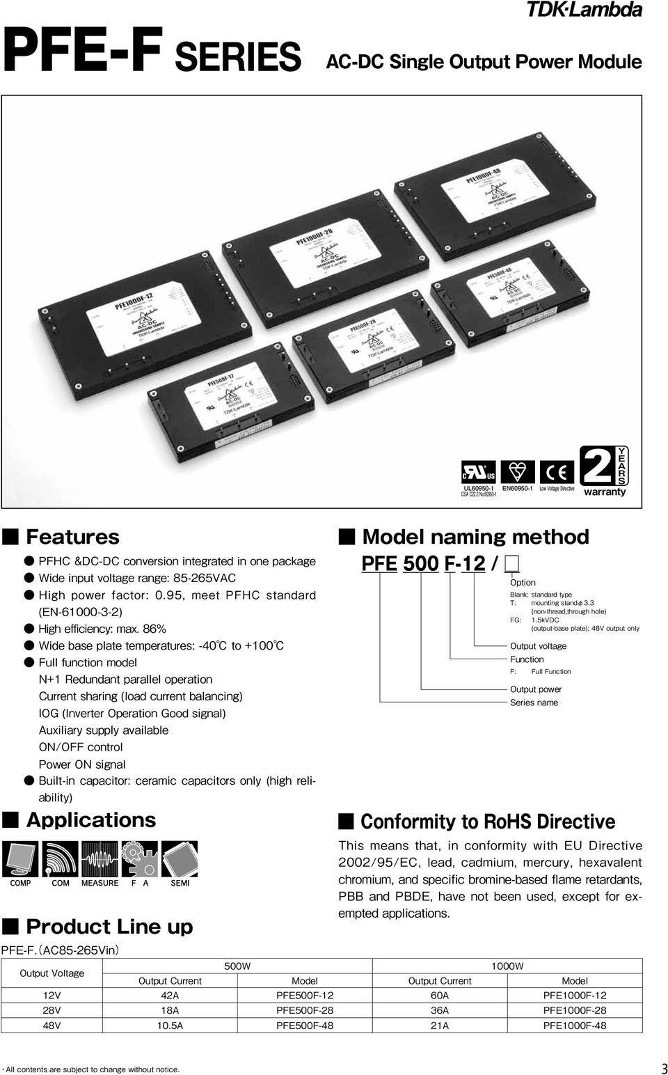
1 AC-DC Single Output Power Module

2 PFHC (AC-DC Conversion) and DC-DC Conversion Integrated in One Package. 2-in-1 Design Concept One module now contains the functions previously only obtainable by combining a front-end module with a high voltage input DC-DC converter. The product is made using a wide range input AC-DC front end function (harmonic current control and power factor correction) and DC-DC back-end (voltage conversion and isolation) in 1 package). Huge reduction in space Full Function (F type) By utilizing output current balancing function, parallel operation up to 6 units is possible. ON/OFF Control. ON/OFF control is possible even there is no ON/OFF in input circuit. ON/OFF control circuit is in between primary & secondary isolation. Inverter Operation Good signal Auxiliary Supply available old product PFE Series Enhanced Surge Immunity Level It is possible to clear 6kV surge voltage in normal and common mode (absorber is installed in the input filter). High Power Density:0.95/ High Efficiency:89%/ Input Voltage:85265VAC PFHC is provided, primary and secondary isolation for better safety and wide input range. High efficiency with up to 100 base plate temperatures. PFE500S-12, PFE500F-12: Up to 85 Solution to Serve Different Kinds of Market Demands PFE series features offer many reliable solutions Thanks to its compact size and reduction in cost, power distribution is easier to construct than before. More over, high power density and N+1 redundant parallel operation increase the reliability. High base plate temperature and 6kV surge immunity level makes PFE series suitable to be used in harsh outdoor environment. After all, new functions are added to each models to give reliable solution to many market demands. PFE Series AC Input EMI Filter Regulated Output Load 12V,28V,48V Application Example
 By utilizing output current balancing function, parallel operation up to 6 units is possible. ON/OFF Control.")
3 PFE-FSERIES 2 3
4 PFE500F PFE500F Specifications Input Voltage Range (*2) (*5) V VAC Frequency (*2) Hz Power Factor (*1)(*5) 0.95 Efficiency (Typ) (*1) 81 / / 86 Current (*1) A 6.8 / / 3.2 Inrush Current (Typ) (*1)(*5) A 20 / 40 peak Nominal Voltage (*1) VDC Maximum Current A Maximum Power W 504 Voltage Setting Accuracy +/-2 Output Maximum Line Regulation mv Maximum Load Regulation mv Maximum Ripple & Noise (*5) mvp-p Voltage Adjustable Range -20 / +20 Over Current Protection Over Voltage Protection (*8) Remote Sensing (*6) Possible Function Remote ON/OFF Control (*6) Possible Parallel Operation (*6) Possible Series Operation (*6) Possible Operating Temperature (*3)(*7) (Baseplate) (Baseplate) Storage Temperature Operating Humidity RH (No Dewdrop) Storage Humidity RH (No Dewdrop) Environment At no operating, 10-55Hz (Sweep for 1min.) Vibration Amplitude 0.825mm constant (Maximum 49.0m/s²) X,Y,Z 1 hour each Shock 196.1m/s² Cooling (*4) Conduction Cooled Standards Safety Standards Approved by UL , CSA C22.2 No , EN Input-Baseplate Withstand Voltage Isolation Isolation Resistance (*1) At 100VAC/200VAC and maximum output power. (Baseplate Temperature = +25C.) (*2) For cases where conformance to various safety specs (UL, CSA, EN) are required, input voltage range will be VAC(50/60Hz). (*3) Ratings - refer to Derating Curve on the right. (*4) Heatsink has to be chosen according to Instruction manual. (*5) External components are needed for operation. (Refer to basic connection and instruction manual.) (*6) Refer to Instruction manual. (*7) Ambient Temperature min=-40c (*8) OVP reset : Line off or Control off. (Refer to instruction manual.) Derating Curve 105% - 140% (Automatic recovery method) 125% - 145% (Inverter shutdown method) : 2.5kVAC, Input-Output : 3.0kVAC for 1min. Output-Baseplate : 500VDC for 1min. Output-Baseplate 500VDC more than 100M (25C,70%RH) Weight (Typ) g 300 Mechanical Size (W x H x D) mm 70 x 12.7 x 122 (Refer to Outline Drawing) 4
 Remote Sensing (*6) Possible Function Remote ON/OFF Control (*6) Possible Parallel Operation (*6) Possible Series Operation (*6)")
5 PFE500F PFE500F Outline Drawing LC AC (N) INPUT: VAC 8A 50/60Hz OUTPUT:48V 10.5A AC (L) +V +V R PFE500F-48 AC-DC +BC BAR CODE -BC E N S PC +ON/OFF -ON/OFF AUX MADE IN JAPAN -V +S TRIM IOG ENA COM -V -S +S PC TRIM +ON/OFF IOG -ON/OFF ENA AUX COM NOTES: A: Model name, input voltage range, Nominal output voltage, Maximum output current, country of manufacture and safety marking (C-UL-US, BSI & CE marking) are shown here in accordance with the specifications. B: M3 tapped holes 4 for customer chassis mounting (FG). C: Output terminal : 2-2 D: Input and Intermediate terminal : 5-1 E: Signal pin (+S, -S, TRIM, ENA, IOG, AUX, +ON/OFF, -ON/OFF, PC, COM) : F: Unless otherwise specified dimensional tolerance : 0.3 5
.")
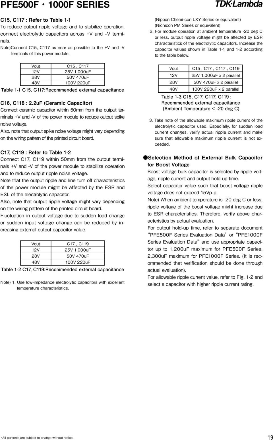
6 PFE500F Basic Connection F1 AC250V 15A C pF R1 0.5W 470k C uF C1 AC250V 1uF (Film) C uF C2 2200pF 12V: 25V 1000uF (Elec.) C3 2200pF C15 28V: 50V 470uF (Elec.) C4 AC250V 1uF (Film) 48V: 100V 220uF (Elec.) C5 AC250V 1uF (Film) C16 100V 2.2uF (Ceramic) C6 2200pF 12V: 25V 1000uF (Elec.) C7 2200pF C17 28V: 50V 470uF (Elec.) C8 450V 1uF (Film) 48V: 100V 220uF (Elec.) C9 450V 1uF (Film) TFR C (Res., Thermal fuse) C10 450V 390uF (Elec.) L1 6mH C11 450V 390uF (Elec.) L2 6mH (*1) Use an external fuse of fast blow type for each unit. (*2) The allowable ripple current of capacitor must be more than 3A(rms). (*3) Put this capacitor near the terminal as close as possible. (*4) The maximum capacitance that can be used is less than 1200uF(Rated capacitance). Avoid the connection of capacitance which is more than above, else it will lead to module to damage. (*5) The inrush current at AC throw in can be suppressed by the external Resistor (Built-in thermal fuse) connected between the R and +BC terminals. (*6) If the ambient temperature is less than -20C, use twice the recommended capacitor above. (*7) Refer to instruction manual for further details. 6
 L2 6mH (*1) Use an external fuse of fast blow type for each unit. (*2) The allowable ripple current of capacitor must be more than 3A(rms).")
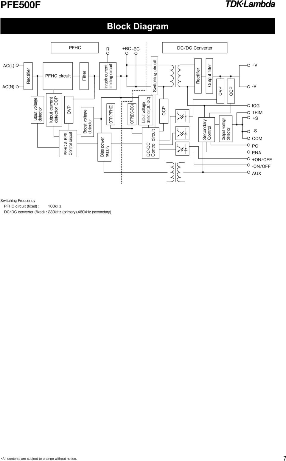
7 PFE500F 7 Block Diagram
8 PFE500F 8 Sequence Time Chart

9 PFE1000F PFE1000F Specifications Input Voltage Range (*2)(*3) V VAC Frequency (*2) Hz Power Factor (*1)(*3) 0.95 Efficiency (Typ) (*1) 80 / / 86 Current (*1) A 9.8 / / / 6.5 Inrush Current (Typ) (*1)(*3) A 20 / 40 peak Nominal Voltage (*1) VDC Maximum Current A Maximum Power W Voltage Setting Accuracy +/-2 Output Maximum Line Regulation mv Maximum Load Regulation mv Maximum Ripple & Noise (*3) mvp-p Voltage Adjustable Range -20 / +20 Over Current Protection (*4)(*5) 105% - 140% Over Voltage Protection (*5) 125% - 145% (Inverter shutdown method) Remote Sensing (*6) Possible Function Remote ON/OFF Control (*6) Possible Parallel Operation (*6) Possible Series Operation (*6) Possible Operating Temperature (*7)(*8) (Baseplate) Storage Temperature Operating Humidity RH (No Dewdrop) Storage Humidity RH (No Dewdrop) Environment At no operating, 10-55Hz (Sweep for 1min.) Vibration Amplitude 0.825mm constant (Maximum 49.0m/s²) X,Y,Z 1 hour each Shock 196.1m/s² Cooling (*9) Conduction Cooled Input-Baseplate Withstand Voltage Isolation Isolation Resistance Standards Safety Standards : 2.5kVAC, Input-Output : 3.0kVAC for 1min. Output-Baseplate : 500VDC for 1min. Output to Baseplate 500VDC more than 100M (25C,70%RH) Approved by UL , CSA , EN Weight (Typ) g 500 Mechanical Size (W x H x D) mm 100 x 13.4 x 160 (Refer to Outline Drawing) (*1) At 100VAC/200VAC and maximum output power. (Baseplate Temperature = +25C.) (*2) For cases where conformance to various safety specs (UL, CSA, EN) are required, input voltage range will be VAC(50/60Hz). (*3) External components are needed for operation. (Refer to basic connection and instruction manual.) (*4) Constant current limiting. (The unit automatically shutdown when left in OCP condition, with the output voltageless than the LVP level. Refer to instruction manual.) (*5) Reset : Line off or Control off. (Refer to instruction manual.) (*6) Refer to Instruction manual. (*7) Ambient Temperature min=-40c (*8) Ratings - refer to Derating Curve. (*9) Heatsink has to be chosen according to Instruction manual. Derating Curve 9
 mvp-p 120 280 480 Voltage Adjustable Range -20 / +20 Over Current Protection (*4)(*5) 105% - 140% Over Voltage Protection (*5)")
10 PFE1000F PFE1000F Outline Drawing AC (N) AC (L) PFE1000F-48 INPUT : VAC 16A 50/60Hz OUTPUT : 48V 21A AC-DC R +BC -BC E N MADE IN JAPAN -S PC +ON/OFF -ON/OFF AUX -V -V -V +V +V +V +S TRIM IOG ENA COM NOTES: A: Model name, input voltage range, Nominal output voltage, Maximum output current, country of manufacture and safety marking (C-UL-US, BSI & CE marking) are shown here in accordance with the specifications. B: M3 tapped holes 4 for customer chassis mounting (FG). C: Output terminal : 6-2 D: Input and Intermediate terminal : 5-2 E: Signal pin (+S, -S, TRIM, ENA, IOG, AUX, +ON/OFF, -ON/OFF, PC, COM) : F: Unless otherwise specified dimensional tolerance :
 : 10-0.")
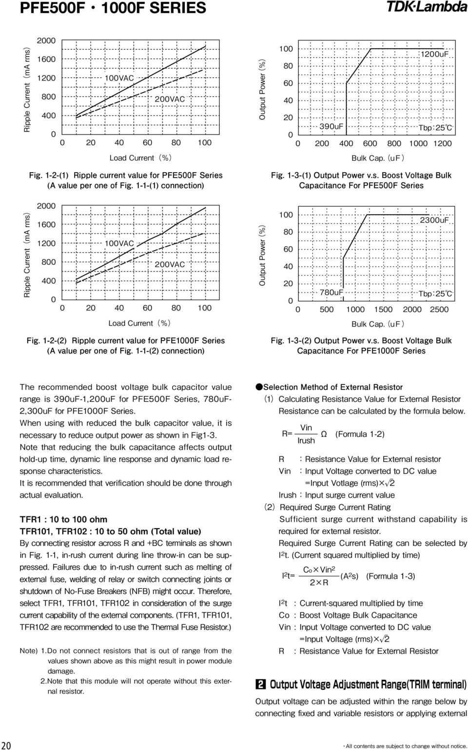
11 PFE1000F Basic Connection F1 F25AH250V C uF C1 AC250V 1uF (Film) C uF C2 470pF 12V25V 1000uF (Elec.) C3 470pF C17 28V50V 470uF (Elec.) C4 AC250V 1uF (Film) 48V100V 220uF (Elec.) C5 AC250V 1uF (Film) C18 100V 2.2uF (Ceramic) C6 4700pF 12V25V 1000uF (Elec.) C7 4700pF C19 28V50V 470uF (Elec.) C8 AC250V 1uF (Film) 48V100V 220uF (Elec.) C9 450V 1uF (Film) R1 0.5W470k C10 450V 1uF (Film) TFR (Res., Thermal fuse) C11 450V 390uF (Elec.) TFR (Res., Thermal fuse) C12 450V 390uF (Elec.) L1 2mH C13 450V 390uF (Elec.) L2 2mH C14 450V 390uF (Elec.) L3 2mH (*1) Use an external fuse of fast blow type for each unit. (*2) The allowable ripple current of capacitor must be more than 3A(rms). (*3) Put this capacitor near the terminal as close as possible. (*4) The maximum capacitance that can be used is less than 2300uF(Rated capacitance). Avoid the connection of capacitance which is more than above of else it will lead to module damage. (*5) The inrush current at AC throw in can be suppressed by the external Resistor (Built-in thermal fuse) connected between the R and +BC terminals. (*6) If the ambient temperature is less than -20C, use twice the recommended capacitor above. (*7) Refer to instruction manual for further details. 11
 L3 2mH (*1) Use an external fuse of fast blow type for each unit. (*2) The allowable ripple current of capacitor must be more than 3A(rms).")
12 Block Diagram PFE1000F 12

13 Sequence Time Chart PFE1000F 13

14 PFE500F1000F SERIES 14 PFE500F, 1000F SERIES Instruction Manual

15 PFE500F1000F SERIES 15

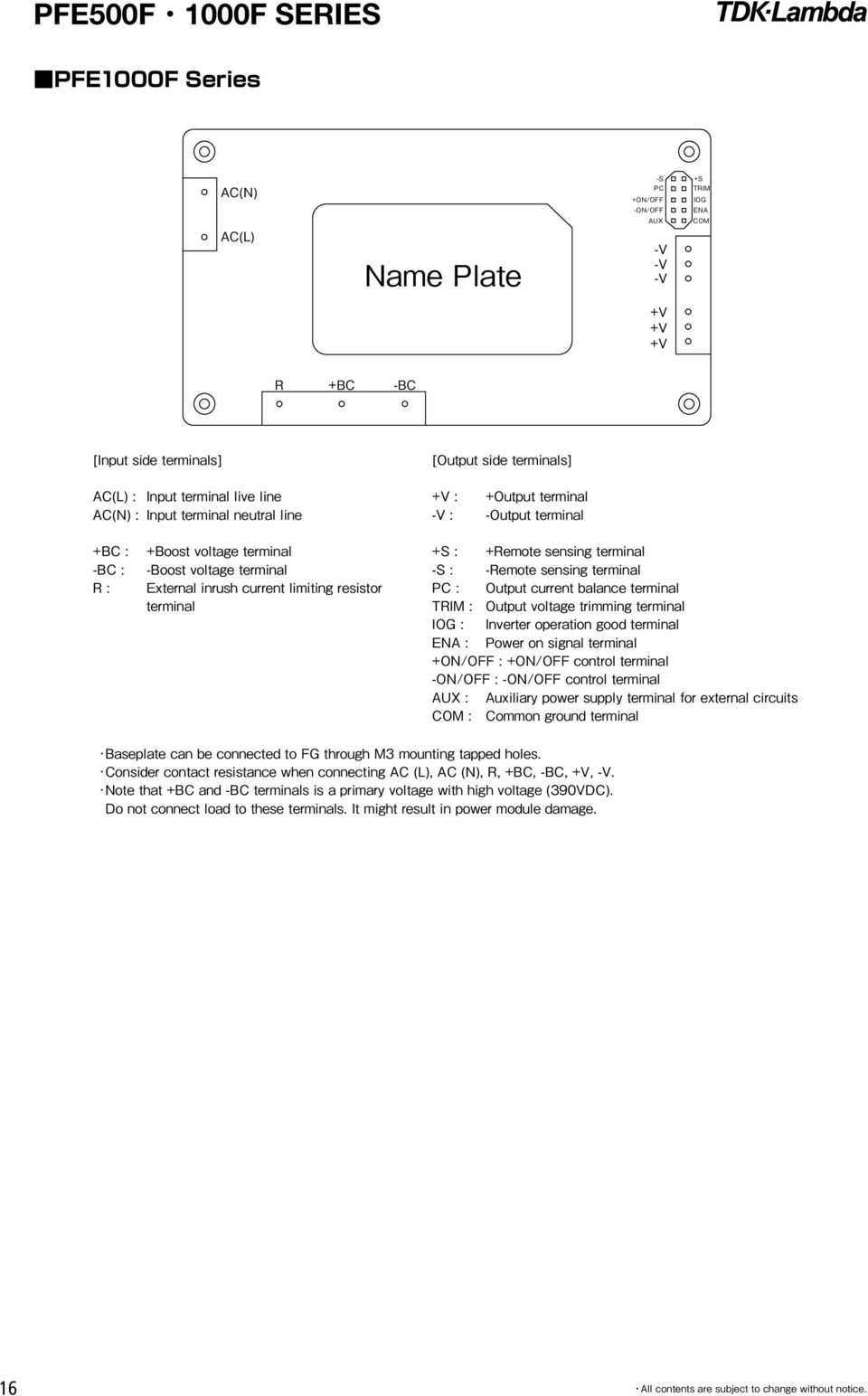
16 PFE500F1000F SERIES 16
17 PFE500F1000F SERIES 17

18 PFE500F1000F SERIES 18
19 PFE500F1000F SERIES 19
20 PFE500F1000F SERIES 20
21 PFE500F1000F SERIES 21
22 PFE500F1000F SERIES 22
23 PFE500F1000F SERIES 23
24 PFE500F1000F SERIES 24 -
25 PFE500F1000F SERIES 25
26 PFE500F1000F SERIES 26
27 PFE500F1000F SERIES 27
28 PFE500F1000F SERIES 28
29 PFE-SSERIES 2 29
30 PFE300S PFE300S Specifications Voltage Range (*2)(*5) V AC Frequency (*2) Hz Input Power Factor (min) (*1)(*5) 0.95 Efficiency (typ) (*1) 81 / / 85 Current (*1) A 4.0 / 2.0 Inrush Current (typ) (*1)(*5) A 20 / 40 peak Nominal Voltage (*1) VDC Maximum Current A Maximum Power W Output Voltage Setting Accuracy 2 Maximum Line Regulation mv Maximum Load Regulation mv Maximum Ripple Voltage (*5) mvp-p Voltage Adjustable Range -20% / +20% Over Current Protection 105% - 140% (Automatic recovery method) Over Voltage Protection 125% - 145% (Inverter shutdown method) Function Parallel Operation - Series Operation (*6) Possible Operating Temperature (*3)(*7) -40 to +100 (Baseplate) Storage Temperature -40 to +100 Operating Humidity RH (No dewdrop) Storage Humidity RH (No dewdrop) Environment At no operating, 10-55Hz (sweep for 1min.) Vibration Amplitude 0.825mm constant (maximum 49.0m/s²) X, Y, Z 1 hour each Shock 196.1m/s² Cooling (*4) Conduction cooled Input-Baseplate : 2.5kVAC, Input-Output : 3.0kVAC for 1min. Withstand Voltage Isolation Output-Baseplate : 1.5kVDC for 1min. Isolation Resistance Output to Baseplate 500VDC more than 100M (25, 70%RH) Standards Safety Standards Approved by UL , CSA C22.2 No , EN Weight (typ) g 250 Mechanical Size (W x H x D) mm 61 x 12.7 x (Refer to outline drawing.) (*1) At 100VAC/200VAC and maximum output power. (Baseplate temperature = +25.) (*2) For cases where conformance to various safety specs (UL, CSA, EN) are required, input voltage range will be VAC (50/60Hz). (*3) Ratings - refer to derating curve below. (*4) Heatsink has to be chosen according to instruction manual. (*5) External components are needed for operation. (Refer to basic connection and instruction manual.) (*6) Refer to instruction manual. (*7) Ambient temperature min=-40 Derating Curve 30
31 PFE500S PFE500S Specifications Input Voltage Range (*2)(*5) V AC Frequency (*2) Hz Power Factor (min) (*1)(*5) 0.95 Efficiency (typ) (*1) 82 / / 86 Current (*1) A 5.0 / / 3.2 Inrush Current (typ) (*1)(*5) A 20 / 40 peak Nominal Voltage (*1) VDC Maximum Current A Maximum Power W Output Voltage Setting Accuracy 2 Maximum Line Regulation mv Maximum Load Regulation mv Maximum Ripple & Noise (*5) mvp-p Voltage Adjustable Range -20% / +20% Over Current Protection 105% - 140% (Automatic recovery method) Over Voltage Protection 125% - 145% (Inverter shutdown method) Function Parallel Operation - Series Operation (*6) Possible Operating Temperature (*3)(*7) -40 to +85 (Baseplate) -40 to +100 (Baseplate) Storage Temperature -40 to +100 Operating Humidity RH (No dewdrop) Storage Humidity RH (No dewdrop) Environment At no operating, 10-55Hz (sweep for 1min.) Vibration Amplitude 0.825mm constant (maximum 49.0m/s²) X, Y, Z 1 hour each Shock 196.1m/s² Cooling (*4) Conduction cooled Input-Baseplate Withstand Voltage Isolation Isolation Resistance Standards Safety Standards : 2.5kVAC, Input-Output : 3.0kVAC for 1min. Output-Baseplate : 1.5kVDC for 1min. Output to Baseplate 500VDC more than 100M (25, 70%RH) Approved by UL , CSA C22.2 No , EN Weight (typ) g 250 Mechanical Size (W x H x D) mm 61 x 12.7 x (Refer to outline drawing.) (*1) At 100VAC/200VAC and maximum output power. (Baseplate temperature = +25.) (*2) For cases where conformance to various safety specs (UL, CSA, EN) are required, input voltage range will be 100 ~ 240VAC (50/60Hz). (*3) Ratings - refer to derating curve on the right. (*4) Heatsink has to be chosen according to instruction manual. (*5) External components are needed for operation. (Refer to basic connection and instruction manual.) (*6) Refer to instruction manual. (*7) Ambient temperature min=-40 Derating Curve 31
32 PFE300S, 500S Outline Drawing Basic Connection NOTES: A: Model name, input voltage range, nominal output voltage, maximum output current, country of manufacture and safety marking (C-UL-US, BSI & CE marking) are shown here in accordance with the specifications. B: M3 tapped holes 4 for customer chassis mounting (FG). C: Output terminal : 2-2 D: Input, Intermediate terminal and signal pin: 9-1 E: Unless otherwise specified dimensional tolerance : 0.3 F1 AC250V 15A C9 450V 1uF (Film) C15 100V 2.2uF (Ceramic) C1 AC250V 1uF (Film) C10 PFE300S:450V 470uF x1 (Elec.) C16 12V: 25V 1000uF (Elec.) C2 4700pF PFE500S:450V 390uF x2 (Elec.) 28V: 50V 470uF (Elec.) C3 4700pF C pF 48V: 100V 220uF (Elec.) C4 AC250V 1uF (Film) C uF R1 2W 470k C5 AC250V 1uF (Film) C uF TFR (Res., Thermal fuse) C6 1000pF C14 12V: 25V 1000uF (Elec.) L1 6mH C7 1000pF 28V: 50V 470uF (Elec.) L2 6mH C8 450V 1uF (Film) 48V: 100V 220uF (Elec.) Note: Except C10, above components list is for both PFE300S and PFE500S Series Please select component standards, withstand voltage, etc based on the application. 32
33 PFE700S PFE700S Specifications Voltage Range (*2)(*5) V AC Frequency (*2) Hz Input Power Factor (min) (*1)(*5) 0.95 Efficiency (typ) (*1) 86 / 89 Current (*1) A 8.8 / 4.4 Inrush Current (typ) (*1)(*5) A 20 / 40 peak Nominal Voltage (*1) VDC 51 Voltage Regulation Range (*7) V Maximum Current A 14 Output Maximum Power W 714 Voltage Setting Accuracy (*1) 1 V Maximum Ripple & Noise (*5) 4 Vp-p Over Current Protection 105% - 140% (Automatic recovery method) Over Voltage Protection VDC (Inverter shutdown method) Function Parallel Operation (*6) Possible Series Operation (*6) Possible Operating Temperature (*3) -40 to +100 (Baseplate), Ambient temperature min=-40 Storage Temperature -40 to +100 Operating Humidity RH (No dewdrop) Storage Humidity RH (No dewdrop) Environment At no operating, 10-55Hz (sweep for 1min.) Vibration Amplitude 0.825mm constant (maximum 49.0m/s²) X, Y, Z 1 hour each Shock 196.1m/s² Cooling (*4) Conduction cooled Withstand Voltage Isolation Input-Baseplate : 2.5kVAC, Input-Output : 3.0kVAC for 1min. Output-Baseplate : 1.5kVDC for 1min. Isolation Resistance Output to baseplate 500VDC more than 100M (25, 70%RH) Standards Safety Standards Approved by UL , CSA C22.2 No , EN Weight (typ) g 250 Mechanical Size (W x H x D) mm 61 x 12.7 x (Refer to outline drawing.) (*1) At 100VAC/200VAC and maximum output power. (Baseplate temperature = +25.) (*2) For cases where conformance to various safety specs (UL, CSA, EN) are required, input voltage range will be VAC (50/60Hz). (*3) Ratings - refer to Derating Curve on the right. (*4) Heatsink has to be chosen according to Instruction manual. (*5) External components are needed for operation. (Refer to basic connection and instruction manual.) (*6) Refer to Instruction manual. (*7) For all input voltage, output load and temperature range. Derating Curve 33
34 PFE700S Outline Drawing Basic Connection NOTES A: Model name, input voltage range, Nominal output voltage, Maximum output current, country of manufacture and safety marking (C-UL-US, BSI & CE marking) are shown here in accordance with the specifications. B: M3 tapped holes 4 for customer chassis mounting (FG). C: Output terminal : 2-2 D: Input, Intermediate terminal and signal pin: 9-1 (NC : Make no external connection) E: Unless otherwise specified dimensional tolerance : 0.3 F1 AC250V 15A C7 1000pF C14 48V: 100V 220uF (Elec.) C1 AC250V 1uF (Film) C8 450V 1uF (Film) C15 100V 2.2uF (Ceramic) C2 4700pF C9 450V 1uF (Film) C16 100V 220uF (Elec.) C3 4700pF C10 450V 390uF x2 Parallel (Elec.) R1 2W 470k C4 AC250V 1uF (Film) C pF TFR (Res., Thermal fuse) C5 AC250V 1uF (Film) C uF L1 6mH C6 1000pF C uF L2 6mH Note: Please select component standards, withstand voltage, etc based on the application. 34
35 35 PFE300S, 500S Sequence Time Chart Block Diagram
36 36 Block Diagram Sequence Time Chart PFE700S
37 PFE300S, 500S 37 PFE300S, 500S Instruction Manual
38 PFE300S, 500S 38
39 PFE300S, 500S 39
40 PFE300S, 500S 40
41 PFE300S, 500S 41
42 PFE300S, 500S 42
43 PFE300S, 500S 43
44 PFE300S, 500S 44
45 PFE700S 45 PFE700S Instruction Manual
46 PFE700S AC(N) V AC(L) Name Plate +V VM +VM NC ENA R +BC BC 46
47 PFE700S 47
48 PFE700S 48
49 PFE700S 49
50 PFE700S 50
51 PFE700S 51
52 52
53 53
Instruction Manual PFE300S 500S SERIES. TDK-Lambda PFE300S 500S Series INSTRUCTION MANUAL
 PFE300S 500S SERIES Instruction Manual TDK-Lambda PFE300S 500S Series BEFORE USING THE POWER SUPPLY UNIT Be sure to read this instruction manual thoroughly before using this product. Pay attention to all
650W Single Output Power Supply
 AK-650 series Features : Universal AC input with active PFC Programmable output Voltage ( 0% ~ 05% ) Programmable output Current ( % ~ 05% ) High efficiency up to 9% + / 0.5A auxiliary output Intelligent
650W Single Output Power Supply 15V 24V. 27V 48V Rated Current. 0 ~ 100A 0 ~ 50A 0 ~ 40A 0 ~ 27A 0 ~ 24A 0 ~ 13.6A Rated Power
 Features: Universal AC input / Full range Programmable output Voltage (0% ~ 05%) Programmable output Current (% ~ 05%) + / 0.5A auxiliary output Forced current sharing at parallel operation Power OK signal
1000W Single Output Power Supply 15V 24V. Protection type: Total Power limit, Latch-style (Recovery after reset AC power ON or inhibit)
") 000W Single Output Power Supply AK-000 series Features: Universal AC input / Full range Programmable output Voltage (0% ~ 05%) Programmable output Current (% ~ 05%) + / 0.5A auxiliary output U profile,
000W Single Output Power Supply AK-000 series Features: Universal AC input / Full range Programmable output Voltage (0% ~ 05%) Programmable output Current (% ~ 05%) + / 0.5A auxiliary output U profile,
TEP 200WIR Series, 180 240 Watt
 TEP 200WIR Series, 180 240 Watt Features Chassis mount with screw terminal block Including EMI filter to meet EN 55022, class A Ultra wide 4:1 input voltage ranges 8.5 36, 16.5 75, 43 160 VDC EN 50155
Single Output Switching Power Supply
 .. RS- Code: CLP-A Single Output Switching Power Supply SPECIFICATION MODEL OUTPUT INPUT PROTECTION ENVIRONMENT SAFETY EMC (Note 6) OTHERS NOTE DC VOLTAGE RATED CURRENT CURRENT RANGE RATED POWER RIPPLE
O WA-120U series IP67. 120W Single Output Switching Power Supply. Features. Aplications
 Features UniversalACinput/Fulrange Built-inactivePFCfunction Higheficiencyupto91% Protections:Shortcircuit/Overcurent/ Overvoltage/Overtemperature Fanlesdesign,colingbyfreairconvection Colingbyfreairconvection
AC/DC Power Modules C B. TML Series, 20 & 40 Watt. Features. 20 Watt Models
 TML Series, 0 & 0 Watt Features C B Scheme LVD UL 090- Encapsulated power supplies with increased power density Replaces TML and TML 0 series PCB mount or chassis mount with screw terminals Single, dual
RoHS APPROVAL SHEET. ituner 12V/6.6A SERIES NO. (E17) EA10953A. ( ) Edac Power Electronics (Suzhou) Co., Ltd. 59 No.59, Chang Sheng Road, Sheng Pu,
 EA10953A. ( ) Edac Power Electronics (Suzhou) Co., Ltd. 59 No.59, Chang Sheng Road, Sheng Pu,") APPROVAL SHEET CUSTOMER ituner CUSTOMER P/N DESCRIPTION EDAC MODEL 12V/6.6A SERIES NO. (E17) EA10953A DATE 2010-06-22 REVISION 0 APPROVED DESIGN PREPARE RoHS CONCLUSION APPROVED CONDITON CUSTOMER S APP
APPROVAL SHEET CUSTOMER ituner CUSTOMER P/N DESCRIPTION EDAC MODEL 12V/6.6A SERIES NO. (E17) EA10953A DATE 2010-06-22 REVISION 0 APPROVED DESIGN PREPARE RoHS CONCLUSION APPROVED CONDITON CUSTOMER S APP
CPCI-3U-AC-300W-R. Rugged 300W AC Input 3U CompactPCI Power Supply. Electrical Specification for: Telkoor Part Number: 900-4602-0000
 Electrical Specification for: CPCI-3U-AC-300W-R Rugged 300W AC Input 3U CompactPCI Power Supply Telkoor Part Number: 900-4602-0000 GENERAL SCALE RELEASE DATE 12/9/06 SHEET 1 OF 6 REVISION HISTORY Rev Level
Series AMEPR30-AZ up to 2.5A AC-DC / DC-DC LED Driver / Converter
 FEATURES: Click on Series name for product info on aimtec.com Models Single output Model Max Output Power (W) 1 AC-DC Constant Current or Constant Over temperature protection Voltage LED Driver Over current
UMEC International Corporation
 UP1301A SERIES 130 Watt Open Frame Switchers Small Size 3*5*1.2(inches) Universal Input to 264 VAC Low Power Consumption Overvoltage Protection Continuous Short Circuit Protection Over Temperature Protection
Series AMLDL-Z Up to 1000mA LED Driver
 FEATURES: Click on Series name for product info on aimtec.com Series Up to ma LED Driver Models Single output Model Input Voltage (V) Step Down DC/DC LED driver Operating Temperature range 4ºC to 85ºC
HFE1600 Series 1600W 1U Hot Swap Front End Power Supplies
 25.2W/in 3 power density Internal ORing MOSFET & Current Share Climate Savers Computing efficiency standards Up to 8000W in 1U rack Single and dual output 1U racks PMBus option HFE1600 Series 1600W 1U
EPL225 Series. 225 Watts. www.xppower.com. AC-DC Power Supplies. Models & Ratings. Summary
 225 Watts 50 W Convection/ 225 W Forced-cooled Ratings 2 by 4 Footprint Low.26 Profile 2 V Fan Output High Efficiency, up to 95% ITE & Medical pprovals High Power Density Less than 0.5 W No Load Input
NFF Series. CoolX600 NFF Series Cool. Patented Resonant Technology. NFF Series; No Fan Featured
 Cool TM 600 NFF Series Patented Resonant Technology NFF Series; No Fan Featured 100% natural convection cooled No internal or external fans needed No base-plate needed No Acoustic Noise or Vibrations &
Chrome DIN Rail Power Supply 24V 91.2W 1 Phase (Class II & NEC Class 2) / DRC-24V100W1AZ
 / DRC-24V100W1AZ") Highlights & Features Protection Class II, Double Isolation (No Earth connection is required) Universal AC input voltage without power de-rating Efficiency > 87.0% @ 115Vac, > 89.0% @ 230Vac NEC Class
Highlights & Features Protection Class II, Double Isolation (No Earth connection is required) Universal AC input voltage without power de-rating Efficiency > 87.0% @ 115Vac, > 89.0% @ 230Vac NEC Class
GWS250 Series Instruction Manual
 GWS250 Series Instruction Manual BEFORE USING THE POWER SUPPLY UNIT Pay attention to all warnings and cautions before using the unit. Incorrect usage could lead to an electrical shock, damage to the unit
Chrome DIN Rail Power Supply 24V 30W 1 Phase (Class II & NEC Class 2) / DRC-24V30W1AZ
 / DRC-24V30W1AZ") Highlights & Features Protection Class II, Double Isolation (No Earth connection is required) Universal AC input voltage without power de-rating Efficiency > 87.0% @ 115Vac & 230Vac NEC Class 2 / Limited
Highlights & Features Protection Class II, Double Isolation (No Earth connection is required) Universal AC input voltage without power de-rating Efficiency > 87.0% @ 115Vac & 230Vac NEC Class 2 / Limited
www.jameco.com 1-800-831-4242
 Distributed by: www.jameco.com 1-800-831-4242 The content and copyrights of the attached material are the property of its owner. 15W Output Switching ower Supply NFM-15 s e ries SECIFICATION MODEL OUTUT
Maximum Input Current Vin=18V, 100% Load 12.6 13.1 A
 FEATURES Wide input voltage range, 18~60V 200W Output @ 18V~27V Vin range 300W Output @ 27~60V Vin range (Including 27V) Full Load Efficiency up to 88.3% @48Vin Intergrated fuse holder Parallel Connection
Antec TruePower User's Manual
 User s Manual Antec TruePower User's Manual Antec TruePower ATX12V power supply Models: TRUE330, TRUE380, TRUE430, TRUE480, TRUE550 Antec Low Noise Technology: The Antec TruePower power supply is equipped
ALIMENTATORI SWITCHING MONOFASE DA 75W CON FUNZIONE PFC 75W, SINGLE PHASE, SWITCHING POWER SUPPLY WITH PFC FUNCTION
 ALIMENTATORI SWITCHING MONOFASE DA 7W CON FUNZIONE PFC 7W, SINGLE PHASE, SWITCHING POWER SUPPLY WITH PFC FUNCTION Tensione di ingresso universale 90 ~ 6Vac Universal input voltage : 90 ~ 6Vac Funzione
Application Note TMA Series
 1W, SIP, Single & Dual Output DC/DC Converters Features SIP Package with Industry Standard Pinout Package Dimension: 19.5 x 10.2 x 6.1 mm (0.77 x 0.4 x 0.24 ) 5V&12V Models 19.5 x 10.2 x 7.1 mm (0.77 x
PWM-90 series IP67 TRC ELECTRONICS, INC. 1.888.612.9514. www.trcelectronics.com/meanwell. Mean Well PWM-90 Series
 TRC ELECTRONICS, INC. 90W PWM output LED power LED supply Power Supply Constant Voltage PFC High Efficiency 90W Ⅱ Ⅱ IP67 TRC ELECTRONICS, INC. 90W PWM output LED power supply SPECIFICATION MODEL OUTPUT
SST-ST70F-ESB SST-ST60F-ESB
 STRIDER ESSENTIAL SERIES Power for everything you need SST-ST70F-ESB SST-ST60F-ESB High efficiency with 80 PLUS Bronze certification 24/7 continuous power output with 40 operating temperature Class-leading
38 Series - Relay interface modules 0.1-2 - 3-5 - 6-8 A
 38 Series - Relay interface modules 0.1-2 - 3-5 - 6-8 A Common features Instant ejection of relay by plastic retaining clip Integral coil indication and protection circuit EMR Electromechanical Relays
SUCCESS EPCOS Capacitors
 SUCCESS EPCOS Inc. Capacitors Group April, 2012 EV / HV / E-Mobility Battery charger system & Inverter On Board and Off Board Assembly Trend: Wireless Charging DC/DC Converter Filtering DC Link E-Mobility
帝 聞 企 業 股 份 有 限 公 司 DEE VAN ENTERPRISE CO., LTD. SP-235864 DSL-20WA 420024 1 Revision: A Date: 2011.10.24 FOR AC-DC LED DRIVER MODEL NO.
 CUSTOMER: PART NUMBER: A200 APPROVAL SHEET FOR AC-DC LED DRIVER MODEL NO. DSL-20WA 420024 1 ORDER NO: SP-235864 承 認 書 确 認 后 請 簽 回 一 份 CUSTOMER APPROVED SIGNATURE DEE VAN ENTERPRISE CO., LTD (Head-Quarter)
Datasheet. Arrant-Light Oy. 120W DR Series 3.8.2015
 3.8.2015 Arrant-Light Oy Datasheet 120W DR Series DR120 Series 120W Single Output LED Driver Features: Constant current and voltage output Universal AC input 100~305VAC Built in active PFC function Output
PWM-60 series IP67 TRC ELECTRONICS, INC. 1.888.612.9514. www.trcelectronics.com/meanwell
 60W PWM output LED power supply Ⅱ IP67 Ⅱ TRC ELECTRONICS, 60W PWM output INC. LED power supply SPECIFICATION MODEL OUTPUT INPUT PROTECTION DC VOLTAGE RATED CURRENT RATED POWER DIMMING RANGE PWM FREQUENCY
7.5 Watt AC-DC Switch Power Supply
 MAIN FEATURES: 7.5W Small Compact Size PCB Mount Single Output Regulated Output Range : 3.3VDC 24VDC Input Range : 85VAC 265VAC/47 63Hz Or 120VDC 370VDC Very Low Standby Power Consumption < 0.15W Better
Power Supply Unit, Primary Switched, Narrow Design MINI-PS-12-24DC/24DC/1
 Power Supply Unit, Primary Switched, Narrow Design MINI POWER provides: Extra narrow design with widths of 22.5 mm, 45 mm, and 67.5 mm (0.886, 1.772, and 2.657 in.) Global use due to a wide-range input
MICROSENS. Central 48 V DC Power Supplies for PoE-Components. Description. Features
 Central 48 V DC Power Supplies for PoE-Components MICROSENS Description Active network equipment which is supporting the Power-over-Ethernet functions, typically requires a powerful 48 V DC power supply.
Power Supplies 3. SDN-P DIN Rail Series
 SDN-P DIN Rail Series The SDN DIN Rail power supplies provide industry leading performance. Sag Immunity, transient suppression and noise tolerant, the SDN series ensures compatibility in demanding applications.
Safety technique. Emergency stop module BO 5988 safemaster
 Safety technique Emergency stop module BO 5988 safemaster 0221562 Function diagram Pushbutton on Mains or emergencystop () K1 According to EC Directive for machines 98/37/EG According to IEC/E 60204-1
PB-600 series. 600W Single Output Battery Charger SPECIFICATION MODEL PB-600-12 PB-600-24 PB-600-48 14.4V 28.8V 57.6V 13.8V
 .. 600W Single Output Charger PB600 series SPECIFICATION MODEL OUTPUT INPUT PROTECTION FUNCTION ENVIRONMENT SAFETY & EMC (Note 2) OTHERS NOTE BOOST CHARGE VOLTAGE FLOAT CHARGE VOLTAGE RECOMMENDED BATTERY
Positive-guided relay outputs: 3 safety contacts (N/O), instantaneous. 1 auxiliary contact (N/C), instantaneous
, instantaneous. 1 auxiliary contact (N/C), instantaneous") Safety relay for monitoring E-STOP pushbuttons. Approvals Unit features Positive-guided relay outputs: 3 safety contacts (N/O), instantaneous 1 auxiliary contact (N/C), instantaneous Safe separation of
Safety relay for monitoring E-STOP pushbuttons. Approvals Unit features Positive-guided relay outputs: 3 safety contacts (N/O), instantaneous 1 auxiliary contact (N/C), instantaneous Safe separation of
Chrome DIN Rail Power Supply 12V 54W 1 Phase (Class II & NEC Class 2) / DRC-12V60W1AG
 / DRC-12V60W1AG") Highlights & Features Protection Class II, Double Isolation (No Earth connection is required) Universal AC input voltage and full power up to 55 C Power will not de-rate for the entire input voltage range
Highlights & Features Protection Class II, Double Isolation (No Earth connection is required) Universal AC input voltage and full power up to 55 C Power will not de-rate for the entire input voltage range
www.murata-ps.com D1U54P-W-1200-12-HxxC Series 54mm 1U Front End AC-DC Power Supply Converter www.murata-ps.com/support PRODUCT OVERVIEW FEATURES
 www.murata-ps.com PRODUCT OVERVIEW D1U54P-W-1200-12-HxxC Series The D1U54P-W-1200-12-HxxC series are 80 PLUS Platinum effi ciency 1200 watt, power factor corrected front end supplies with a 12V main output
MODEL TUHS3F05 TUHS3F12 TUHS3F24 VOLTAGE[V] AC85-264 1f DC120-370
![MODEL TUHS3F05 TUHS3F12 TUHS3F24 VOLTAGE[V] AC85-264 1f DC120-370](/thumbs/40/21139431.jpg "MODEL TUHS3F05 TUHS3F12 TUHS3F24 VOLTAGE[V] AC85-264 1f DC120-370") AC-DC Power Supplies PCB Mount Type TUHS3 Ordering information TUH S 3 F 05 1 2 3 4 5 R 1 Series name 2 Single output 3 Output wattage 4 Universal Input 5 Output voltage *Avoid short circuit between +BC
AC-DC Power Supplies PCB Mount Type TUHS3 Ordering information TUH S 3 F 05 1 2 3 4 5 R 1 Series name 2 Single output 3 Output wattage 4 Universal Input 5 Output voltage *Avoid short circuit between +BC
Your Advantages For safety application up to PL e / Cat. 4 e.g. SIL 3 Manual or automatic start 0225592. * see variants. Applications.
 Safety Technique SAFEMASTER Emergency Stop Module BG 5924, IP 5924 Your Advantages For safety application up to PL e / Cat. 4 e.g. SIL 3 Manual or automatic start 0225592 BG 5924 IP 5924 Product Description
* Requires external power line filter and hold up capacitors; see typical applica on circuit and app notes for details
 The 8500 module contains all of the necessary circuitry for complete power line compliance with aeronau cs specifica on RTCA/DO 60G and Boeing's D6 36440(C)*. It is a pin for pin and form fit compa ble
CAUTION! THE 7I29 USES VOLTAGE AND POWER LEVELS THAT REPRESENT A HAZARD TO LIFE AND LIMB.
 7I29 MANUAL Rev 1.5 CAUTION! THE 7I29 USES VOLTAGE AND POWER LEVELS THAT REPRESENT A HAZARD TO LIFE AND LIMB. THE 7I29 IS INTENDED FOR USE BY OEMS THAT WILL INTEGRATE IT INTO A SYSTEM WITH INTERLOCKS AND
Top Microsystems Proprietary Specification P/N: W090015HK-XP 022410RB-082709V.A0 SPECIFICATION
 SPECIFICATION High Quality Switching Wallmount Adapter Interchangeable AC Plugs 90-264VAC Input 13.5W 9VDC 1.5A Output P/N: W090015HK-XP ** Specification Approval** This specification (total 11 pages including
RISH EM 3490 DS Dual Source Energy Meter RISH EM 3490 DS. Application : Product Features:
 Application : RISH Master 3490 DS measures important electrical parameters of Utility (in normal mode) & Generators (in Power back up) in three phase and single phase Network & replaces the multiple analog
SELECTION GUIDE. Nominal Input
 www.murata-ps.com NKE Series FEATURES RoHS Compliant Sub-Miniature SIP & DIP Styles 3kVDC Isolation UL Recognised Wide Temperature performance at full 1 Watt load, 40 C to 85 C Increased Power Density
CliQ DIN Rail Power Supply 24V 120W 1 Phase / DRP024V120W1AA
 Highlights & Features Reliable design, with expected life of 10 years Compact, rugged design for ease of handling and installation Multiple connections to terminals allowed Designed for Class I Div. 2
MODEL PBA300F-3R3 PBA300F-5 PBA300F-7R5 PBA300F-12 PBA300F-15 PBA300F-24 PBA300F-36 PBA300F-48 MAX OUTPUT WATTAGE[W] 198 300 300 324 330 336 324 336
![MODEL PBA300F-3R3 PBA300F-5 PBA300F-7R5 PBA300F-12 PBA300F-15 PBA300F-24 PBA300F-36 PBA300F-48 MAX OUTPUT WATTAGE[W] 198 300 300 324 330 336 324 336](/thumbs/40/21042120.jpg "MODEL PBA300F-3R3 PBA300F-5 PBA300F-7R5 PBA300F-12 PBA300F-15 PBA300F-24 PBA300F-36 PBA300F-48 MAX OUTPUT WATTAGE[W] 198 300 300 324 330 336 324 336") PBA/PBW AC-DC Power Supplies Enclosed Type PBA300F Ordering information PB A 300 F -5 -O 1 2 3 4 5 6 R Recommended EMI/EMC Filter NAC-06-472 High voltage pulse noise type : NAP series Low leakage current
PBA/PBW AC-DC Power Supplies Enclosed Type PBA300F Ordering information PB A 300 F -5 -O 1 2 3 4 5 6 R Recommended EMI/EMC Filter NAC-06-472 High voltage pulse noise type : NAP series Low leakage current
Lockout Hysteresis Voltage 1 2 3 VDC Maximum Input Current Vin=18V, 100% Load 13.0 13.5 A Vin=24V 180 220 ma
 FEATURES Ultra wide input voltage range, 18~106V 200W Output @ 18V~27V Vin range 300W Output @ 27~106V Vin range (Including 27V) Full Load Efficiency up to 91.0% @48Vin Intergrated fuse holder Parallel
47000 SERIES - ELECTRONIC TRANSFORMERS
 7000 SERIES - ELECTRONIC TRANSFORMERS MYRRA encapsulated electronic transformers are Switched Mode Power Supplies based on Flyback topology. They constitute an interesting alternative to the traditional
DC-DC Converter Module
 45 Features DC input range: 250-425V Input surge withstand: 500V for 100ms DC output: 24V Programmable output: 10 to 110% Regulation: ±0.2% no load to full load Efficiency: 88% Maximum operating temperature:
400-800. Series OMEGA WATTS POWER SUPPLY AC/DC SINGLE OR MULTIPLE OUTPUT. Flexible modular design. Programmable outputs** Power factor correction***
 INPUT Input protection Thermal protection Switching frequency internal fuse standard 100KHz Input with PFC : (MML400PFC, MML600, MML800) Input voltage range 85*-264VAC Inrush current (peak) MML400PFC
RCP-1000 / RCP-1U Instruction Manual
 RCP- / RCP-U Instruction Manual . Safety Guidelines.... Introduction of Series Models.... Introduction.... Features.... Order Information....4 Main Specification.... Mechanical Specification and Input
UL/ RAILWAYS Certified Constant Current LED Driver Wide Input and Output Voltage Range Digital PWM and Analogue Voltage Dimming
 Features Regulated Converters Selection Guide UL/ RAILWAYS Certified Constant Current LED Driver Wide Input and Output Voltage Range Digital PWM and Analogue Voltage Dimming Short Circuit Protected Pinned
38 Series - Relay interface modules 0.1-2 - 3-5 - 6-8 - 16 A
 38 Series - Relay interface modules 0.1-2 - 3-5 - 6-8 - 16 A 38 SERIES Common features Instant ejection of relay by plastic retaining clip Integral coil indication and protection circuit EMR Electromechanical
7-41 POWER FACTOR CORRECTION
 POWER FTOR CORRECTION INTRODUCTION Modern electronic equipment can create noise that will cause problems with other equipment on the same supply system. To reduce system disturbances it is therefore essential
Silvertel. Ag5200. 1 Features. 2 Description. Power-over-Ethernet Plus Module. IEEE802.3at and IEEE802.3af compliant. Maximum 30W output power
 Silvertel V1.1 November 2012 Datasheet Pb 1 Features IEEE802.3at and IEEE802.3af compliant Maximum 30W output power Dual In-Line (DIL) package size 50.6mm (L) x 30mm (W) Overload, short-circuit and thermal
VI-HAM, VE-HAM VxHAMxL
 VI-HAM, VE-HAM VxHAMxL Actual Size: 4.6 x 2.4 x 0.5 in (116,8 x 61,0 x 12,7 mm) C US C S NRTL US High-Boost Harmonic Attenuation Module Features 675 Watts output power Unity power factor 85 264 Vac universal
WINGLIKE ELECTRONICS CO.,LTD
 WINGLIKE ELECTRONICS CO.,LTD SPECIFICATION FOR APPROVAL AC/DC ADAPTOR CUSTOMER: CUSTOMER SPECS INPUT: 100-240V AC 50-60HZ, 5V/2A ADAPTOR OUR MODEL NO.: GM-050200 (UL) E321192 SPECIFICATION NO.: WL1105102
33.6W Power over Ethernet Waterproof Adapter PoE Plus Single Port Injector for Outdoor Application
 33.6W Power over Ethernet Waterproof Adapter PoE Plus Single Port Injector for Outdoor Application Features Compliant with the IEEE802.3at Standard -40 to +60 C Temperature Range Diagnostic LEDs Full Protection
STEP-PS/1AC/12DC/1.5. Extract from the online catalog. Order No.: 2868567. DIN rail power supply unit 12 V DC/1.5 A, primary switched-mode, 1- phase
 Extract from the online catalog STEP-PS/1AC/12DC/1.5 Order No.: 2868567 DIN rail power supply unit 12 V DC/1.5 A, primary switched-mode, 1- phase Commercial data EAN 4046356292924 Pack 1 pcs. Customs tariff
Technical Specification for 5VDC/2A +12VDC/2A Adapter
 Technical Specification for 5VDC/2A +12VDC/2A Adapter Contents 1. SCOPE This specification defines the performance characteristics of a grounder,single phase, 34 Watt,2 outputs power supply.this specification
Product Family of Capacitor Chargers PS-17XX for 1500J/Sec in the range 500Vac to 1,000Vac PS-22XX for 2200J/Sec in the range 500Vac to 1,000Vac
 Product Description Capacitor charger power supplies from Digital Power are designed to meet the exacting requirements of medical, aesthetic, and industrial pulsed energy systems. The modular design of
DS 600. A contact free flux gate based current measurement sensor 600A rms
 DS 600 A contact free flux gate based current measurement sensor 600A rms DS 600 is member of the small housing sensor family. The family includes a 200A and a 600A version. 600A rms - 900A peak Maximum
Outdoor 33.6W Dual Port Passive Power-over-Ethernet Midspan For External Security Cameras and Wireless Access Points
 Outdoor 33.6W Dual Port Passive Power-over-Ethernet Midspan For External Security Cameras and Wireless Access Points Features SELV Compliant No Detection Passive Injector Gigabit Compatible Full Protection
DC/DC Converter 9 to 18Vdc and 18 to 36Vdc and 36 to 75Vdc input, 20 Watt Output Power; 3.3 to 15Vdc Single Output and ±12Vdc to ±15Vdc Dual Output
 THN 20 Series Application Note DC/DC Converter 9 to 18Vdc and 18 to 36Vdc and 36 to 75Vdc input, 20 Watt Output Power; 3.3 to 15Vdc Single Output and ±12Vdc to ±15Vdc Dual Output Pending Applications Wireless
3000W Single Output Power Supply
 SPECIFICATION MODEL OUTPUT INPUT POTECTION DC OLTAGE ATED CUENT CUENT ANGE ATED POWE OLTAGE ADJ. ANGE LINE EGULATION LOAD EGULATION SETUP, ISE TIME HOLD UP TIME (Typ.) OLTAGE ANGE FEQUENCY ANGE EFFICIENCY
I STAR COMPUTER CO., LTD
 I STAR COMPUTER CO., LTD Mini Redundant Power Supply 300W+300W for IPC-Computer Model No. TC-300R8 Table of content 1. Introduction...1 2. Specification 2.1 Input Voltage...1 2.2 DC Output...1 2.3 PS-ON
Electronic timer CT-AHD.12 OFF-delayed with 1 c/o (SPDT) contact
 contact") Data sheet Electronic timer CT-AHD.12 OFF-delayed with 1 c/o (SPDT) contact The CT-AHD.12 is an electronic time relay with OFF-delay. It is from the CT-D range. With their MDRC profile and a width of only
Data sheet Electronic timer CT-AHD.12 OFF-delayed with 1 c/o (SPDT) contact The CT-AHD.12 is an electronic time relay with OFF-delay. It is from the CT-D range. With their MDRC profile and a width of only
CliQ DIN Rail Power Supply 24V 120W 1 Phase / DRP024V120W1AA
 Highlights & Features Universal AC input voltage Power will not de-rate for the entire input voltage range Power Boost of 150% for 3 seconds Full corrosion resistant aluminium chassis SEMI F47 certified
R-78xx-0.5 INNOLINE. Features. 0.5 AMP SIP3 Single Output. Derating-Graph (Ambient Temperature) DC/DC-Converter
 DC/DC-Converter") Features Description Efficiency up to 97%,Non isolated, no need for heatsinks Pin-out compatible with LM78XX Linears Very low profile( L*W*H=11.5*7.5*10.2 ) Wide input range.(4.75v ~ 32V) Short circuit
Features Description Efficiency up to 97%,Non isolated, no need for heatsinks Pin-out compatible with LM78XX Linears Very low profile( L*W*H=11.5*7.5*10.2 ) Wide input range.(4.75v ~ 32V) Short circuit
Via dell' Industria, 25-31020 S. Vendemiano (TV) Tel. 0438 470047 Fax. 0438 470100 - www.elettrolab.it e-mail Acquisti@elettrolab.
 Tel. 0438 470047 Fax. 0438 470100 - www.elettrolab.it e-mail Acquisti@elettrolab.") EDB300 Electronic Digital Ballast 300W DSP controlled Features: Electronic digital ballast suitable for 300W HID lamps Built-in PFC (pf>0.98 90-260 Vac full range). EMI filter inside. Compact shape, low
EDB300 Electronic Digital Ballast 300W DSP controlled Features: Electronic digital ballast suitable for 300W HID lamps Built-in PFC (pf>0.98 90-260 Vac full range). EMI filter inside. Compact shape, low
CMR Series Isolated 0.75W Single and Dual Output Isolated DC/DC Converters
 www.murata-ps.com CMR Series SELECTION GUIDE FEATURES Single or Dual Isolated Outputs 1kVDC or 3kVDC options Wide temperature performance at full 0.75W load -40 C to 85C Industry Standard Pinouts 5V, 12V
1.44 kw Programmable DC Power Supplies XLN Series
 Data sheet 1.44 kw Programmable DC Power Supplies XLN Series New Family of High Density System Power Supplies The B&K Precision XLN series are compact, programmable, single-output DC power supplies, suitable
High Power Programmable DC Power Supplies PVS Series
 Data Sheet High Power Programmable DC Power Supplies The PVS10005, PVS60085, and PVS60085MR programmable DC power supplies offer clean output power up to 5.1 kw, excellent regulation, and fast transient
Limited Ericsson Internal
 Limited TABLE PRODUCT OF CONTENTS SPECIFICATION 1 (1) (3) SEC/D Kevin Chen 152-EN/LZT146311 1/131-BMR632 Technical Uen Specification PKL 4 PI series 26-12-4 27-1-11 B D DC/DC converters, Input 36-, Output
AC-DC Converter Application Guidelines
 AC-DC Converter Application Guidelines 1. Foreword The following guidelines should be carefully read prior to converter use. Improper use may result in the risk of electric shock, damaging the converter,
Thyristor-controlled power supplies and battery chargers
 Thyristor-controlled power supplies and battery chargers Input voltage: 115 / 230 VAC, single phase, 50 / 60 Hz or 208 / 400 / 480 VAC, three phases, 50 / 60 Hz Output voltage: 12 / 24 / 48 / 60 / 72 /
APD336.221/.421 3 Outputs 19" DC/DC Converter, 50 Watt
 APD336.221/.421 3 Outputs 19" DC/DC Converter, 50 Watt High efficiency: 79% (@ 48V) DCin wide range: 9...36V or 18...72V DC 8 HP plug in width H15 standard pinout Active inrush current suppression Voltage
E-STOP relays, safety gate monitors
 Unit features Safety features Gertebild ][Bildunterschrift_NOT_Sch.tuer_Licht Safety relay for monitoring E-STOP pushbuttons, safety gates and light beam devices Approvals Gertemerkmale Positive-guided
NOT RECOMMENDED FOR NEW DESIGNS
 28 Volt NOT RECOMMENDED FOR NEW DESIGNS Features Attenuation 0 db from 110 khz to 0 MHz Operating temperature - to +8 C Nominal 28 V input, 0 V to 0 V operation 1.7 to A throughput current Transient suppression
Industrial Power Supplies
 TSP-Series Innovative and Powerful Features! Rugged metal case for harsh industrial environments Shock and vibration proof Worlwide Safety approval package. ATEX certification tested in accordance to IECEX
S24SE/S24DE series 20W Single/Dual Output DC/DC Converter
 FEATURES Efficiency up to 88% Wide input range, 9V-36V Package with Industry Standard Pinout Package Dimension: 25.4 x25.4 x10.2mm (1.0 x1.0 x0.40 )(No HSK) Over voltage protection, hiccup mode Over current
DALI-PWM Signal Converter D A P-04. Applications. Features
 SELV Bauar t gepruf t Sich erheit egelma ge od o s b e wac g ww w. tuv.com ID 000000000 Features Universal AC input / Full range ( up to 305VAC) Convert DALI signal to PWM signal DALI addressable output
LM1084 5A Low Dropout Positive Regulators
 5A Low Dropout Positive Regulators General Description The LM1084 is a series of low dropout voltage positive regulators with a maximum dropout of 1.5 at 5A of load current. It has the same pin-out as
SPEED CONTROL SYSTEM
 SPEED CONTROL SYSTEM INDEX SPEED CONTROL MOTOR FEATURES 144 6W ( 70mm) 153 10W ( 70mm) 155 15W ( 80mm) 157 25W ( 80mm) 159 40W ( 90mm) 161 SPEED CONTROL W ( 90mm) 163 90W ( 90mm) 165 120W ( 90mm) 168 180W
PRODUCT DATA SHEET AUDIO LINE COMBINATION ALC0300-1300
 PRODUCT DATA SHEET AUDIO LINE COMBINATION ALC0300-1300 SCOPE These technical specifications describes the functionalities and features of the Anaview Audio Line Combination ALC0300-1300, an integrated
RCP-2000 / RKP-1U I n s t r u c t i o n M a n u a l
 RCP-000 / RKP-U I n s t r u c t i o n M a n u a l 0.Safety Guidelines.Introduction of Series Models. Introduction. Features.3 Order Information.4 Main Specification.Mechanical Specification and Input /
MEAN WELL SPS USER MANUAL
 MEAN WELL SPS USER MANUAL 1. INPUT 1.1 INPUT VOLTAGE Switching Power Supplies (SPS) are widely used all over the world. Many types of products are available for both alternating and direct current input.
Power Supply, Primary Switch Mode, Narrow Design MINI-PS-100-240AC/2x15DC/1
 Power Supply, Primary Switch Mode, Narrow Design -PS-100-240AC/2x15DC/1 POWER provides: Extra narrow widths of 22.5 and 45 mm (0.886 and 1.772 in.) Global use due to a wide range input A high level of
3000W Single Output Power Supply
 SP-3000 s eries SPECIFICATION MODEL OUTPUT INPUT POTECTION OTHES NOTE DC OLTAGE ATED CUENT CUENT ANGE ATED POWE OLTAGE ADJ. ANGE LINE EGULATION LOAD EGULATION SETUP, ISE TIME HOLD UP TIME (Typ.) OLTAGE
SELECTION GUIDE INPUT CHARACTERISTICS. Voltage set point accuracy. Overall voltage error. Temperature coefficient of output voltage (slope)
") OBSOLETE NMPD0 Series SELECTION GUIDE Order Code Nominal Input Voltage Output Voltage Efficiency (Min.) Power (Max.) V V % W NMPD003C 3. 9.50 NMPD005C 5. 9.5 NMPD0C. 0 0.00 NMPD05C 5. 9 0.00 FEATURES RoHS
OBSOLETE NMPD0 Series SELECTION GUIDE Order Code Nominal Input Voltage Output Voltage Efficiency (Min.) Power (Max.) V V % W NMPD003C 3. 9.50 NMPD005C 5. 9.5 NMPD0C. 0 0.00 NMPD05C 5. 9 0.00 FEATURES RoHS
55K SERIES 28 Vin DC/DC Converter 75 Watt Single & Triple Outputs
 55K SERIES 28 Vin DC/DC Converter 75 Watt Single & Triple Outputs Features High Power Density, Low Profile Packaging Full Output Power at +100 C Baseplate Temperature Switching Power Supply Low Noise Designed
DLP-PU/E Instruction Manual
 Instruction Manual BEFORE USING THE POWER SUPPLY UNIT Pay attention to all warnings and cautions before using the unit. Incorrect usage could lead to an electrical shock, damage to the unit or a fire hazard.
DCS Series 1 kw, 1.2 kw, & 3 kw
 DCS Series 1 kw, 1.2 kw, & 3 kw AVAILABLE WITH LXI STANDARD COMPLIANT ETHERNET Applications Automotive Electronics Rackmount ATE System Battery Charging DCS Series DCS Series: 1 kw, 1.2 kw, & 3 kw DCS
Power Supply, Primary Switch Mode, Narrow Design MINI-PS-100-240AC/24DC/2
 Power Supply, Primary Switch Mode, Narrow Design -PS-100-240AC/24/2 POWER provides: Extra narrow widths of 22.5 and 45 mm (0.886 and 1.772 in.) Global use due to a wide range input A high level of operational
JNIOR. Overview. Get Connected. Get Results. JNIOR Model 310. JNIOR Model 312. JNIOR Model 314. JNIOR Model 410
 The INTEG is an Ethernet I/O (digital, analog) device that monitors and controls a small set of process signals. functions as both basic I/O for integration with another application or system AND as a
S24SE/S24DE series 10W Single/Dual Output DC/DC Converter
 FEATURES Efficiency up to 87% Wide input range, 9V-36V Package with Industry Standard Pinout Package Dimension: 25.4 x25.4 x10.2mm (1.0 x1.0 x0.40 )(No HSK) Over voltage protection, hiccup mode Over current