(12) United States Patent Gomiciaga-Pereda et a1.
|
|
|
- Ezra Scott
- 9 years ago
- Views:
Transcription
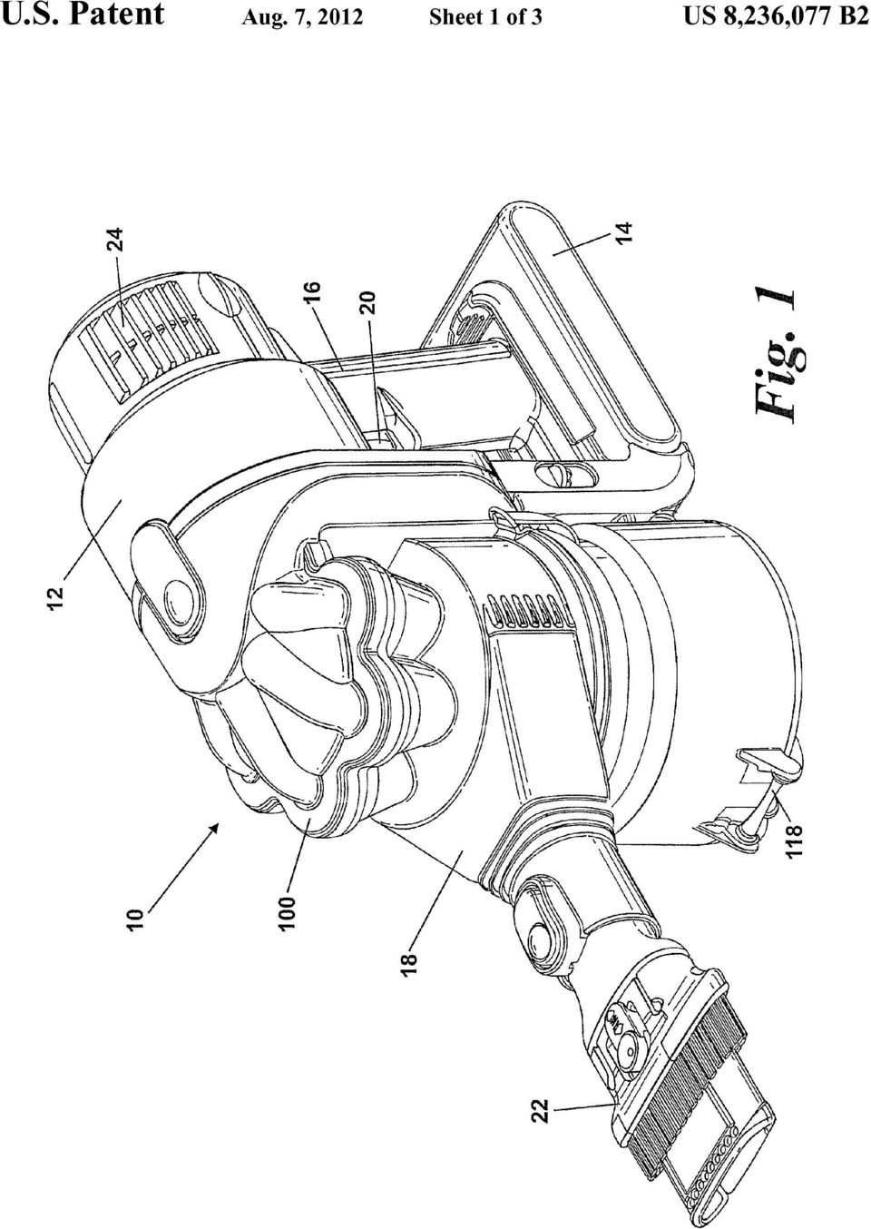
1 US B2 (12) United States Patent Gomiciaga-Pereda et a1. (10) Patent N0.: (45) Date of Patent: US 8,236,077 B2 Aug. 7, 2012 (54) (75) (73) (21) (22) (86) HANDHELD CLEANING APPLIANCE Inventors: Ricardo Gomiciaga-Pereda, Malmesbury (GB); Michael James Peace, Malmesbury (GB) Assignee: Dyson Technology Limited, Malmesbury, Wiltshire (GB) Notice: Subject to any disclaimer, the term of this patent is extended or adjusted under 35 U.S.C. 154(b) by 86 days. Appl. No.: 12/307,249 PCT Filed: Jul. 6, 2007 PCT No.: 371 (0X1) (2), (4) Date: PCT/GB2007/ Aug. 21, 2009 (56) References Cited U.S. PATENT DOCUMENTS 2,399,509 A * 4/1946 Rich /343 D471,683 S * 3/2003 Dyson et al. D32/30 6,582,489 B2* 6/2003 Conrad /337 6,835,222 B2* 12/2004 Gammack /345 D505,761 S * 5/2005 Gammack et al.. D32/21 D518,611 S * 4/2006 Hare..... D32/21 (Continued) FOREIGN PATENT DOCUMENTS CN /2006 (Continued) OTHER PUBLICATIONS International Search Report and Written Opinion mailed on Nov. 6, 2007 directed towards international application No. PCT/GB2007/ ; 9 pages. (Continued) (87) (65) (30) (51) (52) (58) PCT Pub. No.: WO2008/ PCT Pub. Date: Jan. 24, 2008 Jul. 18, 2006 Sep. 20, 2006 Prior Publication Data US 2009/ A1 Dec. 24, 2009 Foreign Application Priority Data (GB) (GB) Int. Cl. B01D 45/00 ( ) US. Cl /343; 55/337; 55/345; 55/346; 55/447; 55/424; 55/428; 55/DIG. 3 Field of Classi?cation Search /343, 55/DIG. 3; 15/353 See application?le for complete search history. Primary Examiner * Jason M Greene Assistant Examiner * Dung H Bui (74) Attorney, Agent, or Firm * Morrison & Foerster LLP (57) ABSTRACT A handheld cleaning appliance includes a dirty air inlet, a clean air outlet and separating apparatus for separating dirt and dust from an air?ow in an air?ow path leading from the air inlet to the air outlet. The separating apparatus includes a cyclonic separator having at least one?rst cyclone and a plurality of second cyclones arranged in parallel With one another and located downstream of the?rst cyclone. By pro viding a cyclonic separator having a plurality of second cyclones in parallel, the handheld cleaning appliance is capable of separating?ne dirt and dust particles Without using barriers such as?lters or bags Which need maintenance to ensure that performance remains high over a period of time. 14 Claims, 3 Drawing Sheets 100
 (2), (4) Date: PCT/GB2007/002529 Aug. 21, 2009 (56) References Cited U.S. PATENT DOCUMENTS 2,399,509 A * 4/1946 Rich..... 55/343 D471,683 S * 3/2003 Dyson et al.")
2 US 8,236,077 B2 Page 2 7,097,680 D555,849 D556,962 D557,469 D557,470 D577,163 D582,115 D583,117 7,488,362 7,537,625 7,547,336 7,547,351 7,563,297 7,563,298 7,601,188 7,651,544 7,655,058 7,686,858 7,686,861 7,731,769 7,749,292 7,771, / / / / / / / / U.S. PATENT DOCUMENTS B2 * 8/2006 Oh..... S * 11/2007 Choi et al. S * 12/2007 Choi et al... S * 12/2007 Choi et al... S * 12/2007 Choi et al... S * 9/2008 Dyson et a1. S * 12/2008 Peace et al.. S * 12/2008 Peace et al.. B2 * 2/2009 Jeong et al.. B2* 5/2009 Han et al. B2 * 6/2009 Fester et al. B2 * 6/2009 Oh et al... B2 * 7/2009 Kim..... B2 * 7/2009 Oh..... B2 * B1 * 10/2009 Hwang et al. 1/2010 Fester et al. B2* 2/2010 Smith..... B2 * 3/2010 Oh B2 * 3/2010 Oh B2* 6/2010 Min B2* 7/2010 Pan et al.. B2* 8/2010 Oh et al A1* 6/2002 Conrad et a A1 12/2002 Maruyama et al. A1* 3/2006 Song et al A1 3/2006 Han et al. A1* 6/2006 Min..... A1* 6/2006 Jeong et al.. A1* 7/2006 Hong et a1.. 55/345 55/ /57 55/343 A1* 10/2006 Oh et al / / A1* 10/2006 Oh etal /343 / 2008/ A1* s/200s Oh etal /416 """" " 55 3/ / A1* 2/2009 Courtneyet a1, 15/347 " Egg/g} 2009/ Al* 12/2009 Gomiciaga-Peredaetal. 55/317 ~~ FOREIGN PATENT DOCUMENTS :1 1332/21 EP /2006,, 1332/31 GB s 9/1970,, 1332/31 GB / GB / GB s/ /337 GB /2006,, 95ml JP s704 9/ /343 JP / /343 JP / /343 JP / /343 W0 WO-01/ / /349 W0 W0-2004/ s/ /345 W0 WO-2006/ / /337 55/ /343 OTHER PUBLICATIONS International Preliminary Report on Patentability completed on Nov. 13, 2008 directed towards international application No. PCT/ GB2007/002529; 6 pages. British Search Report completed on Nov. 8, 2006 directed towards foreign application No. GB ; 1 page. British Search Report completed on Dec. 20, 2006 directed towards foreign application No. GB ; 1 page. cited by examiner

3
4 US. Patent Au Sheet2 0f3 Fig. 2

5 US. Patent Aug. 7, 2012 Sheet 3 of3 US 8,236,077 B " 152\ )4 //// %/ 1 70%.1,, 1 m: 1 :mm. M \/ 11.. mm m Q , /_ K 1 m 1, 3 iamiiy I1. X- l 1 I,!... i I -. - Ii/m w [l11 1 I \ 3 x Q 2 /OMIMUI * <_ / \ // ém F,F /:4, N/ m H W. 4 e0 6 w

6 1 HANDHELD CLEANING APPLIANCE REFERENCE TO RELATED APPLICATIONS This application is a national stage application under 35 USC 371 of International Application No. PCT/GB2007/ ,?led Jul. 6, 2007, Which claims the priority of United Kingdom Application Nos and ,?led Jul. 18, 2006, and Sep. 20, 2006, respectively, the contents of Which prior applications are incorporated herein by refer ence. FIELD OF THE INVENTION The invention relates to a handheld cleaning appliance particularly, but not exclusively, to a handheld vacuum cleaner. More particularly, the invention relates to a handheld cleaning appliance having a cyclonic separator. BACKGROUND OF THE INVENTION Handheld vacuum cleaners are Well known and have been manufactured and sold by various manufacturers for several years. Typically, a handheld vacuum cleaner comprises a casing Which houses a motor and fan unit for drawing air into the cleaner via an inlet, and a separation device such as a?lter or bag for separating dirt and dust from the incoming air?ow. An example of such a vacuum cleaner is shown in GB Handheld vacuum cleaners have more recently been devel oped to incorporate cyclonic separation systems Which are capable of removing larger items of debris from the airflow before removing?ner particles using a?lter or other barrier means. An example of such a device is sold by Black & Decker under the trade name DUSTBUSTER. A further example of a handheld vacuum cleaner incorporating a cyclonic separator is shown in GB A. A disadvantage of known handheld vacuum cleaners Which utilise cyclonic separators is that, When only a single cyclone is used followed by a?lter or bag, the?lter Will require maintenance, either by Washing or by replacement. Failure to maintain the?lter Will result in a decrease in per formance. It is therefore an object of the invention to provide a handheld cleaning appliance Which is capable of sustaining high performance for longer than known handheld vacuum cleaners. It is a further object of the present invention to provide a handheld cleaning appliance Which requires less maintenance than existing appliances. A further object of the present invention is to provide a handheld vacuum cleaner Which is capable of developing and sustaining higher suction power than is possible With current designs of handheld vacuum cleaner. SUMMARY OF THE INVENTION The invention provides a handheld cleaning appliance comprising a dirty air inlet, a clean air outlet and separating apparatus located in an air?ow path leading from the air inlet to the air outlet for separating dirt and dust from an air?ow, the separating apparatus comprising a cyclonic separator hav ing at least one?rst cyclone, Wherein the cyclonic separator further comprises a plurality of second cyclones arranged in parallel With one another and located downstream of the or each?rst cyclone. By providing a cyclonic separator Which comprises a plu rality of second cyclones in parallel, the handheld cleaning appliance becomes capable of separating?ne dirt and dust US 8,236,077 B particles Without using barrier means such as?lters or bags Which need maintenance to ensure that performance remains high over a period of time. It has hitherto been considered dif?cult to provide a cyclonic separator of this type in a handheld vacuum cleaner because the space occupied by this type of cyclonic separator is considered to be too bulky and heavy to be suitable for a handheld machine. A further advan tage of providing a cyclonic separator of this type in a hand held vacuum cleaner is that the cleaner is then capable of sustaining high suction power because there is no barrier-type?lter means to cause a reduction in suction power, and hence pick-up capability, over time. Preferably, the handheld cleaning appliance includes a handle and the cyclonic separator lies between the handle and the dirty air inlet. This provides an arrangement Which is Well balanced for a user of this type of cleaning appliance. It is preferred that the cyclonic separator lies substantially parallel to the handle, and it is further preferred that the cyclonic separator lies in a generally upright con?guration. These features have been found to be bene?cial for manipu lation and for convenient storage and emptying of the dirt and dust collected in the cyclonic separator. In a preferred embodiment of the invention, a single?rst cyclone is provided and the second cyclones are spaced around an axis of the?rst cyclone. This provides a compact arrangement Which is balanced for ease of manipulation. It is more preferable that each of the second cyclones has an end Which projects into the?rst cyclone so as to provide a conve nient balance of dirt collecting capacity and overall volume of the cyclonic separator. BRIEF DESCRIPTION OF THE DRAWINGS An embodiment of the invention Will now be described With reference to the accompanying drawings, in Which: FIG. 1 shows a handheld cleaning appliance according to the invention; FIG. 2 is a side view of the appliance of FIG. 1; and FIG. 3 is a longitudinal cross section through the cyclonic separating apparatus forming part of the appliance of FIG. 1. DETAILED DESCRIPTION OF THE INVENTION FIGS. 1 and 2 show a handheld vacuum cleaner 10. The handheld vacuum cleaner 10 has a main body 12 Which houses a motor and fan unit (not shown). The main body 12 also includes a power source 14 such as a battery. A handle 16 is provided on the main body 12 for manipulating the hand held vacuum cleaner 10 in use. A cyclonic separator 100 is attached to the main body 12. A dirty air inlet 18 extends from a portion of the cyclonic separator 100 remote from the main body 12. A brush tool 22 is slidably mounted on the distal end of the dirty air inlet 18. A set of exhaust vents 24 are provided on the main body 12 for exhausting air from the handheld vacuum cleaner 10. The cyclonic separator 100 is located between the main body 12 and the dirty air inlet 18. Consequently, the cyclonic separator 100 is located between the handle 16 and the dirty air inlet 18. The cyclonic separator 100 has a longitudinal axis 26 Which extends in a generally upright direction so that the axis 26, and therefore the cyclonic separator 100, lies sub stantially parallel to the direction in Which the handle 16 extends. The orientation of the handle 16 is such that, When the user grips the handle 16, the user s hand forms a?st in a manner similar to that adopted When gripping a saw. This ensures that the user s Wrist is not strained more than necessary When

7 3 manipulating the handheld vacuum cleaner 10 for cleaning purposes. The cyclonic separator 100 is positioned close to the handle 16 Which also reduces the moment applied to the user s Wrist When the handheld vacuum cleaner 10 is in use. The handle 16 carries an on/off switch 20 in the form of a trigger for turning the vacuum cleaner motor on and off. The cyclonic separating apparatus 100 forming part of the handheld vacuum cleaner 10 is shown in more detail in FIG. 3. The cyclonic separating apparatus 100 comprises a?rst cyclone 102 Which has a longitudinal axis X-X and a Wall 104. An inlet 110 is formed in the upper portion of the Wall 104. The inlet 110 is in communication With the dirty air inlet 18 and forms a communication path between the dirty air inlet 18 and the interior of the?rst cyclone 102. The air inlet 110 is arranged tangentially to the?rst cyclone 102 so that the incoming air is forced to follow a helical path around the interior of the?rst cyclone 102. Abase 116 closes one end ofthe?rst cyclone 102. The base 116 is pivotably mounted on the lower end of the?rst cyclone Wall 104 by means ofa hinge 118. The base 116 is retained in a closed position (as shown the?gures) by means of a catch 120. A shroud 121 is located inwardly of the Wall 104 of the?rst cyclone 102. The shroud 121 comprises a cylindrical Wall 122 having a plurality of through-holes 123. The shroud 121 surrounds an outlet 124 from the?rst cyclone 102. The outlet 124 provides a communication path between the?rst cyclone 102 and a second cyclone assembly 126.A lip 128 is provided at the base of the shroud 121. The lip 128 has a plurality of through-holes 129 Which are designed to allow air to pass through but to capture dirt and dust. The second cyclone assembly 126 comprises a plurality of second cyclones 130 arranged in parallel With one another. In this embodiment, six second cyclones 130 are provided. The second cyclones 130 are arranged around the axis X-X of the?rst cyclone 102. The arrangement of the second cyclones 130 is such that the second cyclones are spaced equi-angu larly around the axis X-X. Each second cyclone 130 has a tangentially-arranged air inlet 132 and an air outlet 134. Each air inlet 132 and air outlet 134 is located at a?rst end of the respective second cyclone 130. A cone opening 136 is located at a second end of each second cyclone 130. The plane of the cone opening 136 of each second cyclone 130 is inclined With respect to a longitudinal axis (not shown) of the respective further cyclone 130. The cone opening 136 of each of the second cyclones 130 is in communication With a passageway 138 de?ned by a Wall 140 located inwardly of the shroud 121. The second end of each second cyclone 130 projects into the interior of the?rst cyclone 102. HoWever, the?rst end of each second cyclone 130 lies outside the envelope of the?rst cyclone 102. In the orientation shown, it is the lower end of each second cyclone 130 Which projects into the upper end of the?rst cyclone 102. The inlet 110 is also arranged at the upper end of the?rst cyclone 102 so that the inlet 110 is located in the region of the cyclonic separator 100 in Which the?rst and second cyclones 102, 130 overlap. Because the?rst ends of the second cyclones 130 lie outside the envelope of the?rst cyclone, this region of the cyclone separator 100 lies intermediate the upper end of the cyclone separator 100 and the lower end of the cyclone separator 100. Connecting the dirty air inlet 18 to the cyclone separator 100 at an inter mediate portion thereof is bene?cial for the manipulation of the handheld vacuum cleaner 10 and avoids the lower extremities of the appliance being accidentally knocked on surfaces away from the area being cleaned. A collector 142 is located at the lower end of the passage Way 138. The collector 142 comprises a frustoconical?rst US 8,236,077 B portion 144 and a cylindrical second portion 146. The interior of the collector 142 is delimited by the base 116 and the sides of the?rst and second portions 144, 146 of the collector 142. Each of the air outlets 134 of the second cyclones 130 is in communication With a duct 150. The duct 150 provides an air?ow path from the cyclonic separating apparatus 100 into other parts of the handheld vacuum cleaner 1 0. Located at the downstream end of the duct 150 is a pre-motor?lter 152. The pre-motor?lter 152 comprises a porous material such as foam and can also include a?ne?lter material. The pre-motor?lter 152 is designed to prevent any?ne dust particles from enter ing the motor and causing damage thereto. In use, When the on/off switch 20 is depressed, the motor and fan unit draws a How of dirt-laden air into the dirty air inlet 18 and then into the cyclonic separator 100. Dirt-laden air enters the cyclonic separator 100 through the inlet 110. Due to the tangential arrangement of the inlet 110, the air?ow is forced to follow a helical path around the interior of the Wall 104. Larger dirt and dust particles are separated by cyclonic motion around the Wall These particles are then collected at the base 116 of the?rst cyclone 102. The partially-cleaned air?ow then?ows back up the inte rior of the?rst cyclone 102 and exits the?rst cyclone 102 via the through-holes in the shroud 121. Once the air?ow has passed through the shroud 121, it enters the outlet 124 and from there is divided between the tangential inlets 132 of each of the second cyclones 130. Each of the second cyclones 130 has a diameter Which is smaller than that of the?rst cyclone 102. Therefore, the second cyclones 130 are able to separate smaller particles of dirt and dust from the partially-cleaned air?ow than the?rst cyclone Separated dirt and dust exits the second cyclones 130 via the cone openings 136. Thereaf ter, the separated dirt and dust passes down the passageway 138 and into the collector 142. The separated dirt and dust eventually settles at the bottom of the collector 142 on the base 116. Cleaned air then?ows back up the second cyclones 130, exits the second cyclones 130 through the air outlets 134 and enters the duct 150. The cleaned air then passes from the duct 150 sequentially through the pre-motor?lter 152, the motor and fan unit, and a post-motor?lter before being exhausted from the vacuum cleaner 10 through the air vents 24. The?rst cyclone 102 and the collector 142 can be emptied simultaneously by releasing the catch 120 to allow the base 116 to pivot about the hinge 118 so that the separated dirt and dust can fall away from the cyclonic separator 100. This allows ef?cient and reliable emptying of the dirt and dust from the cyclonic separator 100 at periodic intervals conve nient to the user. The invention is not limited to the precise details of the embodiment described above. For example, the number of second cyclones can be varied, as can the detail of their design, such as their cone angle, axis inclination and cone opening inclination. The collected dirt and dust can be released in other Ways, such as by complete removal of the lower portion of the?rst cyclone 102, and the location of the on/ off switch may be varied. The invention claimed is: 1. A handheld cleaning appliance comprising a dirty air inlet, a clean air outlet, a handle, and a separating apparatus located in an air?ow path leading from the dirty air inlet to the clean air outlet for separating dirt and dust from an air?ow, the separating apparatus comprising a cyclonic separator having at least one?rst cyclone and a plurality of second cyclones arranged in parallel With one another and located downstream of the?rst cyclone, and the handle and the dirty air inlet being arranged opposite one another about the cyclonic separator

8 5 wherein a single?rst cyclone is provided and Wherein the second cyclones are spaced around a longitudinal axis of the?rst cyclone. 2. The handheld cleaning appliance of claim 1, Wherein a longitudinal axis of the cyclonic separator lies substantially parallel to the handle. 3. The handheld cleaning appliance of claim 1, Wherein the appliance further comprises a power source comprising a battery. 4. The handheld cleaning appliance of claim 1, Wherein the handle and the dirty air inlet are arranged on opposite sides of a longitudinal axis of the cyclonic separator. 5. The handheld cleaning appliance of claim 1, comprising a main body Which houses a motor and fan unit for drawing air?ow along the air?ow path between the dirty air inlet and the clean air outlet, and a power source con?gured to power the motor and fan unit. 6. The handheld cleaning appliance of claim 1 or 2, Wherein the cyclonic separator lies in a generally upright con?guration. 7. The handheld cleaning appliance of claims 1 or 2, Wherein each of the second cyclones has an end Which projects into the?rst cyclone. 8. The handheld cleaning appliance of claim 7, Wherein the dirty air inlet is connected to the cyclonic separator at a US 8,236,077 B location Which is adjacent the ends of the second cyclones Which project into the?rst cyclone. 9. The handheld cleaning appliance of claim 7, Wherein the cyclonic separator lies in a generally upright con?guration. 10. The handheld cleaning appliance of claim 1 or 2, Wherein the cyclonic separator has a?rst end and a second end and the dirty air inlet is connected to the cyclonic sepa rator at a location intermediate the?rst and second ends thereof. 11. The handheld cleaning appliance of claim 10, Wherein the dirty air inlet is connected to the cyclonic separator at a location Which is adjacent ends of the second cyclones Which project into the?rst cyclone. 12. The handheld cleaning appliance of claim 10, Wherein a single?rst cyclone is provided. 13. The handheld cleaning appliance of claim 12, Wherein the second cyclones are spaced around a longitudinal axis of the?rst cyclone. 14. The handheld cleaning appliance of claim 10, Wherein the cyclonic separator lies in a generally upright con?gura tion.

(12) United States Patent Genn et a1.
 United States Patent Genn et a1.") US008429792B2 (12) United States Patent Genn et a1. (10) Patent N0.: (45) Date of Patent: US 8,429,792 B2 Apr. 30, 2013 (54) SWITCH AND MOTOR ASSEMBLY (56) References Cited (75) (73) (*) (21) (22) (86)
US008429792B2 (12) United States Patent Genn et a1. (10) Patent N0.: (45) Date of Patent: US 8,429,792 B2 Apr. 30, 2013 (54) SWITCH AND MOTOR ASSEMBLY (56) References Cited (75) (73) (*) (21) (22) (86)
(12) United States Patent (10) Patent No.: US 8,253,226 B2 Oguri (45) Date of Patent: Aug. 28, 2012
 United States Patent (10) Patent No.: US 8,253,226 B2 Oguri (45) Date of Patent: Aug. 28, 2012") US008253226B2 (12) United States Patent (10) Patent No.: US 8,253,226 B2 Oguri (45) Date of Patent: Aug. 28, 2012 (54) ELECTRONIC PARTS, AND METHOD FOR (56) References Cited ARRANGING SHIELDING CASE AND
US008253226B2 (12) United States Patent (10) Patent No.: US 8,253,226 B2 Oguri (45) Date of Patent: Aug. 28, 2012 (54) ELECTRONIC PARTS, AND METHOD FOR (56) References Cited ARRANGING SHIELDING CASE AND
United States Patent [191 [11] Patent Number: 4,895,256
![United States Patent [191 [11] Patent Number: 4,895,256](/thumbs/29/13744178.jpg "United States Patent [191 [11] Patent Number: 4,895,256") I United States Patent [191 [11] Patent Number: 4,895,256 Johnston [45] Date of Patent: Jan. 23, 1990 [54] AIR CONDITIONING SUPPLY CARRIER 3,392,874 7/1968 3,627,122 12/1971 [76] Inventor: James E. Johnston,
I United States Patent [191 [11] Patent Number: 4,895,256 Johnston [45] Date of Patent: Jan. 23, 1990 [54] AIR CONDITIONING SUPPLY CARRIER 3,392,874 7/1968 3,627,122 12/1971 [76] Inventor: James E. Johnston,
(72) Inventors: Juergen RIEDL, Koenigsbrunn (DE); USPC ( 267/285)
 Inventors: Juergen RIEDL, Koenigsbrunn (DE); USPC ( 267/285)") US 20130087957A1 (19) United States (12) Patent Application Publication (10) Pub. No.: US 2013/0087957 A1 RIEDL et al. (43) Pub. Date: Apr. 11, 2013 (54) DEVICE FOR DAMPING THE VIBRATIONS Publication Classi?cation
US 20130087957A1 (19) United States (12) Patent Application Publication (10) Pub. No.: US 2013/0087957 A1 RIEDL et al. (43) Pub. Date: Apr. 11, 2013 (54) DEVICE FOR DAMPING THE VIBRATIONS Publication Classi?cation
(12) United States Patent (10) Patent N0.: US 7,068,424 B1 Jennings et al. (45) Date of Patent: Jun. 27, 2006
 United States Patent (10) Patent N0.: US 7,068,424 B1 Jennings et al. (45) Date of Patent: Jun. 27, 2006") US007068424B1 (12) United States Patent (10) Patent N0.: US 7,068,424 B1 Jennings et al. (45) Date of Patent: Jun. 27, 2006 (54) MULTIPLE PULSE GENERATION 6,141,127 A * 10/2000 Boivin et a1...... 398/92
US007068424B1 (12) United States Patent (10) Patent N0.: US 7,068,424 B1 Jennings et al. (45) Date of Patent: Jun. 27, 2006 (54) MULTIPLE PULSE GENERATION 6,141,127 A * 10/2000 Boivin et a1...... 398/92
US 20060209260A1 (19) United States (12) Patent Application Publication (10) Pub. No.: US 2006/0209260 A1 Clegg (43) Pub. Date: Sep.
 United States (12) Patent Application Publication (10) Pub. No.: US 2006/0209260 A1 Clegg (43) Pub. Date: Sep.") US 20060209260A1 (19) United States (12) Patent Application Publication (10) Pub. No.: Clegg (43) Pub. Date: Sep. 21, 2006 (54) SCROLLING PICTURE CHANGER (52) US. Cl...... 352/98 (76) Inventor: Timothy
US 20060209260A1 (19) United States (12) Patent Application Publication (10) Pub. No.: Clegg (43) Pub. Date: Sep. 21, 2006 (54) SCROLLING PICTURE CHANGER (52) US. Cl...... 352/98 (76) Inventor: Timothy
17 Claims, 19 Drawing Sheets EG4 SD4 {8L4 ( I; DLI Q P A. \! v,zcll. RG1 7 / l. a U ' 14 A I 1) ~ $133 .. _. _. _. T. _. _. _. /,.
 ~ $133 .. _. _. _. T. _. _. _. /,.") US008564751B2 (12) United States Patent Nakanishi et a]. (10) Patent N0.: (45) Date of Patent: US 8,564,751 B2 Oct. 22, 2013 (54) (75) (73) ( * ) (21) (22) (86) (87) (65) (30) Apr. 17, 2009 (JP)..... 2009-101273
US008564751B2 (12) United States Patent Nakanishi et a]. (10) Patent N0.: (45) Date of Patent: US 8,564,751 B2 Oct. 22, 2013 (54) (75) (73) ( * ) (21) (22) (86) (87) (65) (30) Apr. 17, 2009 (JP)..... 2009-101273
(12) United States Patent (10) Patent N0.: US 8,721,047 B2 Sakurai et a]. (45) Date of Patent: May 13, 2014
![(12) United States Patent (10) Patent N0.: US 8,721,047 B2 Sakurai et a]. (45) Date of Patent: May 13, 2014](/thumbs/39/20155291.jpg "(12) United States Patent (10) Patent N0.: US 8,721,047 B2 Sakurai et a]. (45) Date of Patent: May 13, 2014") USOO8721047B2 (12) United States Patent (10) Patent N0.: US 8,721,047 B2 Sakurai et a]. (45) Date of Patent: May 13, 2014 (54) LIQUID EJECTION HEAD AND INK JET (56) References Cited PRINTING APPARATUS
USOO8721047B2 (12) United States Patent (10) Patent N0.: US 8,721,047 B2 Sakurai et a]. (45) Date of Patent: May 13, 2014 (54) LIQUID EJECTION HEAD AND INK JET (56) References Cited PRINTING APPARATUS
(12) United States Patent Mine et al.
 United States Patent Mine et al.") US008612715B2 (12) United States Patent Mine et al. (10) Patent N0.: (45) Date of Patent: US 8,612,715 B2 *Dec. 17, 2013 (54) (75) (73) (21) (22) (65) (63) (51) (52) (58) STORAGE SYSTEM AND UTILIZATION
US008612715B2 (12) United States Patent Mine et al. (10) Patent N0.: (45) Date of Patent: US 8,612,715 B2 *Dec. 17, 2013 (54) (75) (73) (21) (22) (65) (63) (51) (52) (58) STORAGE SYSTEM AND UTILIZATION
(12) Ulllted States Patent (10) Patent N0.: US 8,389,837 B1 Leguia (45) Date of Patent: Mar. 5, 2013
 Ulllted States Patent (10) Patent N0.: US 8,389,837 B1 Leguia (45) Date of Patent: Mar. 5, 2013") US008389837B1 (12) Ulllted States Patent (10) Patent N0.: US 8,389,837 B1 Leguia (45) Date of Patent: Mar. 5, 2013 (54) STRINGED INSTRUMENT HAVINGA 4,836,076 A 6/1989 Bernier FRETBOARD CANTILEVERED OVER
US008389837B1 (12) Ulllted States Patent (10) Patent N0.: US 8,389,837 B1 Leguia (45) Date of Patent: Mar. 5, 2013 (54) STRINGED INSTRUMENT HAVINGA 4,836,076 A 6/1989 Bernier FRETBOARD CANTILEVERED OVER
(12) United States Patent Yamamoto et a1.
 United States Patent Yamamoto et a1.") US008098756B2 (12) United States Patent Yamamoto et a1. (10) Patent N0.: (45) Date of Patent: US 8,098,756 B2 Jan. 17, 2012 (54) (75) (73) ( * ) (21) (22) (86) (87) (65) (30) (51) (52) (58) MIMO ANTENNA
US008098756B2 (12) United States Patent Yamamoto et a1. (10) Patent N0.: (45) Date of Patent: US 8,098,756 B2 Jan. 17, 2012 (54) (75) (73) ( * ) (21) (22) (86) (87) (65) (30) (51) (52) (58) MIMO ANTENNA
(54) (71) (72) Vedelago (TV) (IT) (73) (21) (22) (30) Chirignago (VE) (IT); Alberto Al?er, Foreign Application Priority Data
 (71) (72) Vedelago (TV) (IT) (73) (21) (22) (30) Chirignago (VE) (IT); Alberto Al?er, Foreign Application Priority Data") US 20130094227Al (19) United States (12) Patent Application Publication (10) Pub. No.: US 2013/0094227 A1 Scordino et al. (43) Pub. Date: Apr. 18, 2013 (54) (71) (72) (73) (21) (22) (30) MOUNTING DEVICE
US 20130094227Al (19) United States (12) Patent Application Publication (10) Pub. No.: US 2013/0094227 A1 Scordino et al. (43) Pub. Date: Apr. 18, 2013 (54) (71) (72) (73) (21) (22) (30) MOUNTING DEVICE
Hay (43) Pub. Date: Oct. 17, 2002
 Pub. Date: Oct. 17, 2002") US 20020152322A1 (19) United States (12) Patent Application Publication (10) Pub. No.: US 2002/0152322 A1 Hay (43) Pub. Date: Oct. 17, 2002 (54) (76) (21) (22) (51) (52) METHOD AND APPARATUS FOR FACILITATING
US 20020152322A1 (19) United States (12) Patent Application Publication (10) Pub. No.: US 2002/0152322 A1 Hay (43) Pub. Date: Oct. 17, 2002 (54) (76) (21) (22) (51) (52) METHOD AND APPARATUS FOR FACILITATING
US 20050027827A1 (19) United States (12) Patent Application Publication (10) Pub. No.: US 2005/0027827 A1 Owhadi et al. (43) Pub. Date: Feb.
 United States (12) Patent Application Publication (10) Pub. No.: US 2005/0027827 A1 Owhadi et al. (43) Pub. Date: Feb.") US 20050027827A1 (19) United States (12) Patent Application Publication (10) Pub. No.: US 2005/0027827 A1 Owhadi et al. (43) Pub. Date: Feb. 3, 2005 (54) SYSTEM FOR PROVIDING SUPPORT FOR AN ELECTRONIC
US 20050027827A1 (19) United States (12) Patent Application Publication (10) Pub. No.: US 2005/0027827 A1 Owhadi et al. (43) Pub. Date: Feb. 3, 2005 (54) SYSTEM FOR PROVIDING SUPPORT FOR AN ELECTRONIC
US 20070139188A1 (19) United States (12) Patent Application Publication (10) Pub. No.: US 2007/0139188 A1 Ollis et al. HOME PROCESSOR /\ J\ NETWORK
 United States (12) Patent Application Publication (10) Pub. No.: US 2007/0139188 A1 Ollis et al. HOME PROCESSOR /\ J\ NETWORK") US 20070139188A1 (19) United States (12) Patent Application Publication (10) Pub. No.: US 2007/0139188 A1 Ollis et al. (43) Pub. Date: Jun. 21, 2007 (54) (75) (73) (21) (22) METHOD AND APPARATUS FOR COMMUNICATING
US 20070139188A1 (19) United States (12) Patent Application Publication (10) Pub. No.: US 2007/0139188 A1 Ollis et al. (43) Pub. Date: Jun. 21, 2007 (54) (75) (73) (21) (22) METHOD AND APPARATUS FOR COMMUNICATING
(30) Foreign Application Priority Data
 Foreign Application Priority Data") US 20040015727A1 (19) United States (12) Patent Application Publication (10) Pub. No.: US 2004/0015727 A1 Lahti et al. (43) Pub. Date: Jan. 22, 2004 (54) SYNCHRONIZATION METHOD (76) Inventors: Jerry Lahti,
US 20040015727A1 (19) United States (12) Patent Application Publication (10) Pub. No.: US 2004/0015727 A1 Lahti et al. (43) Pub. Date: Jan. 22, 2004 (54) SYNCHRONIZATION METHOD (76) Inventors: Jerry Lahti,
US 20070028343A1 (19) United States (12) Patent Application Publication (10) Pub. N0.: US 2007/0028343 A1 Makowka (43) Pub. Date: Feb.
 United States (12) Patent Application Publication (10) Pub. N0.: US 2007/0028343 A1 Makowka (43) Pub. Date: Feb.") US 20070028343A1 (19) United States (12) Patent Application Publication (10) Pub. N0.: US 2007/0028343 A1 Makowka (43) Pub. Date: Feb. 8, 2007 (54) DISPOSABLE PROTECTIVE GARMENT Publication Classi?cation
US 20070028343A1 (19) United States (12) Patent Application Publication (10) Pub. N0.: US 2007/0028343 A1 Makowka (43) Pub. Date: Feb. 8, 2007 (54) DISPOSABLE PROTECTIVE GARMENT Publication Classi?cation
Ulllted States Patent [19] [11] Patent Number: 5,992,923. Wycech [45] Date 0f Patent: Nov. 30, 1999
![Ulllted States Patent [19] [11] Patent Number: 5,992,923. Wycech [45] Date 0f Patent: Nov. 30, 1999](/thumbs/40/20828367.jpg "Ulllted States Patent [19] [11] Patent Number: 5,992,923. Wycech [45] Date 0f Patent: Nov. 30, 1999") US005992923A Ulllted States Patent [19] [11] Patent Number: 5,992,923 Wycech [45] Date 0f Patent: Nov. 30, 1999 [54] REINFORCED BEAM ASSEMBLY 4,923,902 5/1990 Wycech. 4,978,562 12/1990 Wycech. [75] Inventor:
US005992923A Ulllted States Patent [19] [11] Patent Number: 5,992,923 Wycech [45] Date 0f Patent: Nov. 30, 1999 [54] REINFORCED BEAM ASSEMBLY 4,923,902 5/1990 Wycech. 4,978,562 12/1990 Wycech. [75] Inventor:
I4 '2 ORLANDO J. CHIAPPE Y.
 '. ' Dec. 6, 1960 o. J. GHIAPPE 2,963,058 DIE FOR BELLOWS 0R CORRUGA'l- ING MACHINE Filed Jan. 20, 1958 5 Sheets-Sheet 1 ' INVENTOR. I4 '2 ORLANDO J. CHIAPPE Y. - ATTORNEY _ Dec. 6, 1960 o. J. CHIAPPE
car + boat Box Contents x2 x2 22350_DC16_CAR_BOAT_OPSMAN.indd 1 29/7/08 15:27:01
 car + boat Box Contents x x 350_DC6_CAR_BOAT_OPSMAN.indd 9/7/08 5:7:0 SAVE THESE INSTRUCTIONS THIS APPLIANCE IS INTENDED FOR HOUSEHOLD USE ONLY IMPORTANT SAFETY INSTRUCTIONS READ ALL INSTRUCTIONS BEFORE
WASH FILTER REGISTER FOR YOUR FREE 5 YEAR GUARANTEE TODAY OPERATING MANUAL ASSEMBLY. click. click. click
 OPERATING MANUAL ASSEMBLY ON OFF 4 WASH FILTER Wash filter with cold water at least every months. FOR YOUR FREE 5 YEAR GUARANTEE TODAY 5 After registering for your 5 year guarantee, your Dyson vacuum cleaner
(12) United States Patent (10) Patent No.: US 8,512,370 B2 Sorensen (45) Date of Patent: Aug. 20, 2013
 United States Patent (10) Patent No.: US 8,512,370 B2 Sorensen (45) Date of Patent: Aug. 20, 2013") US008512370B2 (12) United States Patent (10) Patent No.: US 8,512,370 B2 Sorensen (45) Date of Patent: Aug. 20, 2013 (54) PILLOW WITH PLURALITY OF BALLS FOR (56) References Cited RELIEVING SINUS AND CONGESTION
US008512370B2 (12) United States Patent (10) Patent No.: US 8,512,370 B2 Sorensen (45) Date of Patent: Aug. 20, 2013 (54) PILLOW WITH PLURALITY OF BALLS FOR (56) References Cited RELIEVING SINUS AND CONGESTION
(12) United States Patent Okazaki et al.
 United States Patent Okazaki et al.") US008401702B2 (12) United States Patent Okazaki et al. (10) Patent N0.: (45) Date of Patent: US 8,401,702 B2 Mar. 19, 2013 (54) ROBOT, AND CONTROL APPARATUS, CONTROL METHOD, AND CONTROL PROGRAM FOR ROBOT
US008401702B2 (12) United States Patent Okazaki et al. (10) Patent N0.: (45) Date of Patent: US 8,401,702 B2 Mar. 19, 2013 (54) ROBOT, AND CONTROL APPARATUS, CONTROL METHOD, AND CONTROL PROGRAM FOR ROBOT
US 20140196633A1 (19) United States (12) Patent Application Publication (10) Pub. N0.: US 2014/0196633 A1 Shaw (43) Pub. Date: Jul.
 United States (12) Patent Application Publication (10) Pub. N0.: US 2014/0196633 A1 Shaw (43) Pub. Date: Jul.") US 20140196633A1 (19) United States (12) Patent Application Publication (10) Pub. N0.: US 2014/0196633 A1 Shaw (43) Pub. Date: Jul. 17, 2014 (54) SECONDARY CONTAINMENT PALLET (52) US. Cl. HAVING FLEXIBLE
US 20140196633A1 (19) United States (12) Patent Application Publication (10) Pub. N0.: US 2014/0196633 A1 Shaw (43) Pub. Date: Jul. 17, 2014 (54) SECONDARY CONTAINMENT PALLET (52) US. Cl. HAVING FLEXIBLE
US 20090157756Al (19) United States (12) Patent Application Publication (10) Pub. No.: US 2009/0157756 A1 Sanvido (43) Pub. Date: Jun.
 United States (12) Patent Application Publication (10) Pub. No.: US 2009/0157756 A1 Sanvido (43) Pub. Date: Jun.") US 20090157756Al (19) United States (12) Patent Application Publication (10) Pub. No.: US 2009/0157756 A1 Sanvido (43) Pub. Date: Jun. 18, 2009 (54) FILE SYSTEM FOR STORING FILES IN Publication Classi?cation
US 20090157756Al (19) United States (12) Patent Application Publication (10) Pub. No.: US 2009/0157756 A1 Sanvido (43) Pub. Date: Jun. 18, 2009 (54) FILE SYSTEM FOR STORING FILES IN Publication Classi?cation
Naylor, Lake OsWego, OR (US) (51) Int_ CL
 (51) Int_ CL") US 20100023688A1 (19) United States (12) Patent Application Publication (10) Pub. No.: US 2010/0023688 A1 Crowther et al. (43) Pub. Date: (54) SYMMETRICAL STORAGE ACCESS ON (86) PCT No.: PCT/US2007/001542
US 20100023688A1 (19) United States (12) Patent Application Publication (10) Pub. No.: US 2010/0023688 A1 Crowther et al. (43) Pub. Date: (54) SYMMETRICAL STORAGE ACCESS ON (86) PCT No.: PCT/US2007/001542
llllllllllllllillllllllllllllllllllllllllllllllllllllllllllllllllllllllllll
 llllllllllllllillllllllllllllllllllllllllllllllllllllllllllllllllllllllllll USOO5535162A United States Patent [19] [11] Patent Number: 5,535,162 Uenoyama [45] Date of Patent: Jul. 9, 1996 [54] ELECTRICALLY
llllllllllllllllllllllllllllllll llllllllllilllllllllllllllllllllllllll
 llllllllllllllllllllllllllllllll llllllllllilllllllllllllllllllllllllll. USOO53284A Unlted States Patent [19] - [11] Patent Number: 5,328,4 Knighton et a]. [] Date of Patent: Jul. 12, 1994 [54] [76] MARTIAL
/ \33 40 \ / \\ \ \ M / 32. 28f 1. (19) United States (12) Patent Application Publication Lawser et al. NETWORK \ 36. SERVlCE 'NTERNET SERVICE
 United States (12) Patent Application Publication Lawser et al. NETWORK \ 36. SERVlCE 'NTERNET SERVICE") (19) United States (12) Patent Application Publication Lawser et al. US 20130336314A1 (10) Pub. N0.: US 2013/0336314 A1 (43) Pub. Date: Dec. 19, 2013 (54) (71) (72) (73) (21) (22) (63) METHOD FOR COMPLETING
(19) United States (12) Patent Application Publication Lawser et al. US 20130336314A1 (10) Pub. N0.: US 2013/0336314 A1 (43) Pub. Date: Dec. 19, 2013 (54) (71) (72) (73) (21) (22) (63) METHOD FOR COMPLETING
US 20020174380A1 (19) United States (12) Patent Application Publication (10) Pub. N0.: US 2002/0174380 A1. Mannarsamy (43) Pub. Date: NOV.
 United States (12) Patent Application Publication (10) Pub. N0.: US 2002/0174380 A1. Mannarsamy (43) Pub. Date: NOV.") US 20020174380A1 (19) United States (12) Patent Application Publication (10) Pub. N0.: US 2002/0174380 A1 Mannarsamy (43) Pub. Date: NOV. 21, 2002 (54) HELPDESK SYSTEM AND METHOD (52) US. Cl...... 714/25
US 20020174380A1 (19) United States (12) Patent Application Publication (10) Pub. N0.: US 2002/0174380 A1 Mannarsamy (43) Pub. Date: NOV. 21, 2002 (54) HELPDESK SYSTEM AND METHOD (52) US. Cl...... 714/25
NOV. 21, 1967 P J, FELLNER, JR 3,353,652 FEEDING AND INDEXING DEVICE FOR PACKAGE HANDLING APPARATUS. Filed May 25, 1967 2 Sheets-Sheet 1 /, 27
 NOV. 21, 1967 P J, FELLNER, JR FEEDING AND INDEXING DEVICE FOR PACKAGE HANDLING APPARATUS Filed May 25, 1967 2 Sheets-Sheet 1..Z., 76 60 A5 27 Q2 29 /, 27 a0 /@ /5 70 74 4 /9.32 5.77% ATTO 2N EY v Nov.
US 20100054637Al (19) United States (12) Patent Application Publication (10) Pub. N0.: US 2010/0054637 A1 TIRPAN (43) Pub. Date: Mar.
 United States (12) Patent Application Publication (10) Pub. N0.: US 2010/0054637 A1 TIRPAN (43) Pub. Date: Mar.") US 20100054637Al (19) United States (12) Patent Application Publication (10) Pub. N0.: US 2010/0054637 A1 TIRPAN (43) Pub. Date: Mar. 4, 2010 (54) ENCLOSURE FOR ITEMS SUSCEPTIBLE TO (52) US. Cl...... 383/64
US 20100054637Al (19) United States (12) Patent Application Publication (10) Pub. N0.: US 2010/0054637 A1 TIRPAN (43) Pub. Date: Mar. 4, 2010 (54) ENCLOSURE FOR ITEMS SUSCEPTIBLE TO (52) US. Cl...... 383/64
United States Patent [19] [11] Patent Number: 5,671,124
![United States Patent [19] [11] Patent Number: 5,671,124](/thumbs/40/20728739.jpg "United States Patent [19] [11] Patent Number: 5,671,124") ' USOO5671124A United States Patent [19] [11] Patent Number: 5,671,124 H0 [45] Date of Patent: Sep. 23, 1997 [54] CIRCUIT BOARD LOCATING DEVICE 3,488,628 1/1970 Lundergan et a1...... 361/767 4,859,108
' USOO5671124A United States Patent [19] [11] Patent Number: 5,671,124 H0 [45] Date of Patent: Sep. 23, 1997 [54] CIRCUIT BOARD LOCATING DEVICE 3,488,628 1/1970 Lundergan et a1...... 361/767 4,859,108
(12) United States Patent (16) Patent N6.= US 6,611,861 B1 Schairer et al. (45) Date of Patent: Aug. 26, 2003
 United States Patent (16) Patent N6.= US 6,611,861 B1 Schairer et al. (45) Date of Patent: Aug. 26, 2003") US006611861B1 (12) United States Patent (16) Patent N6.= Schairer et al. () Date of Patent: Aug. 26, 2003 (54) INTERNET HOSTING AND ACCESS SYSTEM Primary Examiner AyaZ Sheikh AND METHOD Assistant Examiner
US006611861B1 (12) United States Patent (16) Patent N6.= Schairer et al. () Date of Patent: Aug. 26, 2003 (54) INTERNET HOSTING AND ACCESS SYSTEM Primary Examiner AyaZ Sheikh AND METHOD Assistant Examiner
US 20130169877A1 (19) United States (12) Patent Application Publication (10) Pub. N0.: US 2013/0169877 A1 DANG (43) Pub. Date: Jul.
 United States (12) Patent Application Publication (10) Pub. N0.: US 2013/0169877 A1 DANG (43) Pub. Date: Jul.") US 20130169877A1 (19) United States (12) Patent Application Publication (10) Pub. N0.: US 2013/0169877 A1 DANG (43) Pub. Date: Jul. 4, 2013 (54) SUPPLEMENTAL AUDIO AND VISUAL (52) US. Cl. SYSTEM FORA VIDEO
US 20130169877A1 (19) United States (12) Patent Application Publication (10) Pub. N0.: US 2013/0169877 A1 DANG (43) Pub. Date: Jul. 4, 2013 (54) SUPPLEMENTAL AUDIO AND VISUAL (52) US. Cl. SYSTEM FORA VIDEO
(12) United States Patent (10) Patent N0.: US 8,716,730 B2 Wang et al. (45) Date of Patent: May 6, 2014
 United States Patent (10) Patent N0.: US 8,716,730 B2 Wang et al. (45) Date of Patent: May 6, 2014") USOO8716730B2 (12) United States Patent (10) Patent N0.: US 8,716,730 B2 Wang et al. (45) Date of Patent: May 6, 2014 (54) LED MODULE HAVING A PLATFORM WITH (56) References Cited A CENTRAL RECESSION US.
USOO8716730B2 (12) United States Patent (10) Patent N0.: US 8,716,730 B2 Wang et al. (45) Date of Patent: May 6, 2014 (54) LED MODULE HAVING A PLATFORM WITH (56) References Cited A CENTRAL RECESSION US.
United States Patent [19] [11] Patent Number: 4,893,344
![United States Patent [19] [11] Patent Number: 4,893,344](/thumbs/40/21012473.jpg "United States Patent [19] [11] Patent Number: 4,893,344") United States Patent [19] [11] Patent Number: 4,893,344 Triigardh et a1. [45] Date of Patent: Jan. 9, 1990 [54] HEADSET HAVING A POST AURICLE 4,335,281 l/ 1982 Scott et a1...... 379/430 MOUNT AND ARRANGED
United States Patent [19] [11] Patent Number: 4,893,344 Triigardh et a1. [45] Date of Patent: Jan. 9, 1990 [54] HEADSET HAVING A POST AURICLE 4,335,281 l/ 1982 Scott et a1...... 379/430 MOUNT AND ARRANGED
US 20020141557A1 (19) United States (12) Patent Application Publication (10) Pub. No.: US 2002/0141557 A1 STRANDBERG (43) Pub. Date: Oct.
 United States (12) Patent Application Publication (10) Pub. No.: US 2002/0141557 A1 STRANDBERG (43) Pub. Date: Oct.") ---- US 20020141557A1 (19) United States (12) Patent Application Publication (10) Pub. No.: US 2002/0141557 A1 STRANDBERG (43) Pub. Date: (54) SYSTEM AND METHOD FOR PROVIDING AN AUTOMATIC TELEPHONE CALL
---- US 20020141557A1 (19) United States (12) Patent Application Publication (10) Pub. No.: US 2002/0141557 A1 STRANDBERG (43) Pub. Date: (54) SYSTEM AND METHOD FOR PROVIDING AN AUTOMATIC TELEPHONE CALL
CROWN ABUTMENT TOOTH (54) (75) (73) (21) (22) (30) Shogo YAMAMOTO, Shinjuku-ku. GC Corporation, ltabashi-ku (JP) Foreign Application Priority Data
 (75) (73) (21) (22) (30) Shogo YAMAMOTO, Shinjuku-ku. GC Corporation, ltabashi-ku (JP) Foreign Application Priority Data") US 20070190493A1 (19) United States (12) Patent Application Publication (10) Pub. No.: US 2007/0190493 A1 YAMAMOTO et al. (43) Pub. Date: Aug. 16, 2007 (54) (75) (73) (21) (22) (30) DENTAL PROSTHESIS,
US 20070190493A1 (19) United States (12) Patent Application Publication (10) Pub. No.: US 2007/0190493 A1 YAMAMOTO et al. (43) Pub. Date: Aug. 16, 2007 (54) (75) (73) (21) (22) (30) DENTAL PROSTHESIS,
USER GUIDE. Please read carefully before use. Press button to insert or remove wand. Slide wand fully into hose.
 1 Assembling your Dyson 1 2 3 Press button to insert or remove wand. Slide wand fully into hose. 4 5 6 Twist tools before locating. Wind cable around cable winders, in an anti-clockwise direction. USER
(12> Ulllted States Patent (16) Patent N6.= US 6,320,621 B1 Fu (45) Date of Patent: Nov. 20, 2001
 Patent N6.= US 6,320,621 B1 Fu (45) Date of Patent: Nov. 20, 2001") US006320621B1 (12> Ulllted States Patent (16) Patent N6.= Fu (45) Date of Patent: Nov. 20, 2001 (54) METHOD OF SELECTINGADIGITAL 5,818,935 * 10/1998 Maa..... 380/20 ING SERVICE 5.900.908 * 5/1999 Kirkland
US006320621B1 (12> Ulllted States Patent (16) Patent N6.= Fu (45) Date of Patent: Nov. 20, 2001 (54) METHOD OF SELECTINGADIGITAL 5,818,935 * 10/1998 Maa..... 380/20 ING SERVICE 5.900.908 * 5/1999 Kirkland
Ulllted States Patent [19] [11] Patent Number: 6,029,830
![Ulllted States Patent [19] [11] Patent Number: 6,029,830](/thumbs/40/20861563.jpg "Ulllted States Patent [19] [11] Patent Number: 6,029,830") US006029830A Ulllted States Patent [19] [11] Patent Number: 6,029,830 Manookian [45] Date of Patent: Feb. 29, 2000 [54] SPORTS EQUIPMENT HANGING BELT 4,049,126 9/1977 Halverson..... 211/8701 4,052,805
US006029830A Ulllted States Patent [19] [11] Patent Number: 6,029,830 Manookian [45] Date of Patent: Feb. 29, 2000 [54] SPORTS EQUIPMENT HANGING BELT 4,049,126 9/1977 Halverson..... 211/8701 4,052,805
(12) United States Patent (10) Patent No.: US 8,229,231 B2 Cho et a1. (45) Date of Patent: Jul. 24, 2012
 United States Patent (10) Patent No.: US 8,229,231 B2 Cho et a1. (45) Date of Patent: Jul. 24, 2012") US008229231B2 (12) United States Patent (10) Patent No.: US 8,229,231 B2 Cho et a1. (45) Date of Patent: Jul. 24, 2012 (54) METHOD AND APPARATUS FOR ENCODING (56) References Cited AND DECODING IMAGE U.S.
US008229231B2 (12) United States Patent (10) Patent No.: US 8,229,231 B2 Cho et a1. (45) Date of Patent: Jul. 24, 2012 (54) METHOD AND APPARATUS FOR ENCODING (56) References Cited AND DECODING IMAGE U.S.
\ \ \ connection connection connection interface interface interface
 US 20140122910A1 (19) United States (12) Patent Application Publication (10) Pub. No.: US 20140122910 A1 Chiu et al. (43) Pub. Date: May 1, 2014 (54) RACK SERVER SYSTEM AND OPERATION Publication Classi?cation
US 20130073440A1 (19) United States (12) Patent Application Publication (10) Pub. No.: US 2013/0073440 A1 Chen (57)
 United States (12) Patent Application Publication (10) Pub. No.: US 2013/0073440 A1 Chen (57)") US 20130073440A1 (19) United States (12) Patent Application Publication (10) Pub. No.: US 2013/0073440 A1 Chen (43) Pub. Date: Mar. 21, 2013 (54) PAYROLL SYSTEM AND METHOD Publication Classi?cation (76)
US 20130073440A1 (19) United States (12) Patent Application Publication (10) Pub. No.: US 2013/0073440 A1 Chen (43) Pub. Date: Mar. 21, 2013 (54) PAYROLL SYSTEM AND METHOD Publication Classi?cation (76)
5' i > 95 l 4. United States Patent Barnett [151 3,699,515. 1451 Oct. 17, 1972. (opr/oa/al) '0. [22] Filed: Jan. 4, 19,71 [21] Appl. No.
![5' i > 95 l 4. United States Patent Barnett [151 3,699,515. 1451 Oct. 17, 1972. (opr/oa/al) '0. [22] Filed: Jan. 4, 19,71 [21] Appl. No.](/thumbs/19/343585.jpg "5' i > 95 l 4. United States Patent Barnett [151 3,699,515. 1451 Oct. 17, 1972. (opr/oa/al) '0. [22] Filed: Jan. 4, 19,71 [21] Appl. No.") United States Patent Barnett [541 MOVEMENT RESPONSIVE ALARM SYSTEM FOR A VEHICLE [72] Inventor: Howard James Barnett, 4433 North Stanton, Apt. 412, El Paso, Tex. 79920 [22] Filed: Jan. 4, 19,71 [21] Appl.
United States Patent Barnett [541 MOVEMENT RESPONSIVE ALARM SYSTEM FOR A VEHICLE [72] Inventor: Howard James Barnett, 4433 North Stanton, Apt. 412, El Paso, Tex. 79920 [22] Filed: Jan. 4, 19,71 [21] Appl.
Vision Engravers and Routers PRE-Installation Guide. 2015 Vision Engraving & Routing Systems
 Vision Engravers and Routers PRE-Installation Guide Revised: 8/19/2015 Vision Engravers and Routers PRE-Installation Guide All rights reserved. No parts of this work may be reproduced in any form or by
3,213,816. Oct. 26, 1965 42/ V//////////A 22 "71% / ' ///////1 J. SOLANKA. Filed Feb. 25, 1963 2 Sheets-Sheet 1. 34 32 2s 34 3o, 46 48 4o ATTORNEY
 Oct. 26, 1965 J. SOLANKA METHOD AND MEANS FOR SEWING AND SHANKING BUTTONS Filed Feb. 25, 1963 2 Sheets-Sheet 1 J 34 32 2s 34 3o, 46 48 4o Q? V//////////A 22 llhd. I. Val 24 28 _ 42/ "71% / ' ///////1 5o
United States Patent [191
 United States Patent [191 Fancy [54] REDUNDANT SIGNAL CIRCUIT [75] Inventor: Thomas A. Fancy, Westminster, Mass. [73] Assignee: General Electric Company, Schenectady, NY. [211 Appl. No.: 854,973 [22] Filed:
US006282278B1 (12) United States Patent. (10) Patent N0.: US 6,282,278 B1 D0ganata et al. (45) Date 0f Patent: Aug. 28, 2001
 United States Patent. (10) Patent N0.: US 6,282,278 B1 D0ganata et al. (45) Date 0f Patent: Aug. 28, 2001") US006282278B1 (12) United States Patent (10) Patent N0.: US 6,282,278 B1 D0ganata et al. (45) Date 0f Patent: Aug. 28, 2001 (54) UNIVERSAL CONFERENCE CONTROL 5,758,281 * 5/1998 Emery et a1...... 455/428
US006282278B1 (12) United States Patent (10) Patent N0.: US 6,282,278 B1 D0ganata et al. (45) Date 0f Patent: Aug. 28, 2001 (54) UNIVERSAL CONFERENCE CONTROL 5,758,281 * 5/1998 Emery et a1...... 455/428
Please read this owner s Manual carefully before operating the unit. - Cooling - Heating - Dehumidifying - Fan
 Please read this owner s Manual carefully before operating the unit. - Cooling - Heating - Dehumidifying - Fan TABLE OF CONTENTS INTRODUCTION 2 IMPORTANT SAFEGUARDS...2 PACKAGE CONTAINS..2 NAMES OF PARTS.3
(12) (10) Patent N0.: US 6,740,055 B2 Dominguez (45) Date of Patent: May 25, 2004
 (10) Patent N0.: US 6,740,055 B2 Dominguez (45) Date of Patent: May 25, 2004") United States Patent US006740055B2 (12) (10) Patent N0.: US 6,740,055 B2 Dominguez (45) Date of Patent: May 25, 2004 (54) TRAUMA CERVICAL COLLAR 5,016,623 A * 5/1991 Krahenbuhl..... 602/27 5,054,475 A
United States Patent US006740055B2 (12) (10) Patent N0.: US 6,740,055 B2 Dominguez (45) Date of Patent: May 25, 2004 (54) TRAUMA CERVICAL COLLAR 5,016,623 A * 5/1991 Krahenbuhl..... 602/27 5,054,475 A
(12) United States Patent Edelen
 United States Patent Edelen") US008285799B2 (12) United States Patent Edelen (10) Patent N0.: (45) Date of Patent: Oct. 9, 2012 (54) QUOTA-BASED ARCHIVING (75) Inventor: James Edelen, Renton, WA (U S) (73) Assignee: Microsoft Corporation,
US008285799B2 (12) United States Patent Edelen (10) Patent N0.: (45) Date of Patent: Oct. 9, 2012 (54) QUOTA-BASED ARCHIVING (75) Inventor: James Edelen, Renton, WA (U S) (73) Assignee: Microsoft Corporation,
UNITED STATES PATENT AND TRADEMARK OFFICE BEFORE THE BOARD OF PATENT APPEALS AND INTERFERENCES
 UNITED STATES PATENT AND TRADEMARK OFFICE BEFORE THE BOARD OF PATENT APPEALS AND INTERFERENCES Ex parte HUBERTUS BUTTNER, MARCUS VAN HEYDEN, MARKUS DEUTEL, and ALFONS VOLLMUTH Appeal 2009-002387 1 Technology
6months WASH FILTER REGISTER YOUR 2 YEAR GUARANTEE TODAY OPERATING MANUAL ASSEMBLY. clik. clik. clik
 OPERATING MANUAL ASSEMBLY ON/OFF Fo r hard floors F or carpets 2 3 6months WASH FILTER Wash filter with cold water at least every 6 months. YOUR 2 YEAR GUARANTEE TODAY 1 After registering for your 2 year
(Us) (73) Assignee: Avaya Technology Corp. Je?' McElroy, Columbia, SC (US); (21) Appl. No.: 10/413,024. (22) Filed: Apr. 14, 2003 (57) ABSTRACT
 (73) Assignee: Avaya Technology Corp. Je?' McElroy, Columbia, SC (US); (21) Appl. No.: 10/413,024. (22) Filed: Apr. 14, 2003 (57) ABSTRACT") US 20040202300A1 (19) United States (12) Patent Application Publication (10) Pub. No.: US 2004/0202300 A1 Cooper et al. (43) Pub. Date: Oct. 14, 2004 (54) CALL HANDLING USING NON-SPEECH CUES VIA A PERSONAL
US 20040202300A1 (19) United States (12) Patent Application Publication (10) Pub. No.: US 2004/0202300 A1 Cooper et al. (43) Pub. Date: Oct. 14, 2004 (54) CALL HANDLING USING NON-SPEECH CUES VIA A PERSONAL
81121228181116 1 1 1 (
 US008483073B2 (12) Ulllted States Patent (10) Patent N0.: US 8,483,073 B2 Ishikawa et al. (45) Date of Patent: Jul. 9, 2013 (54) TEST APPARATUS AND TEST METHOD 2003/0012141 A1 * l/2003 Gerrevink..... 370/250
20 GALLON WET DRY VACUUM
 20 Gallon Wet & Dry Vacuum 110" Water Lift Vac Motor 24" Front Mount Squeegee Assembly 50' Cord Special Tip Pour Feature Warranty Contractor Tool Kit Includes: Wet p/u Tool, Dry p/u Tool, Crevice Tool,
(12) United States Patent
 United States Patent") US006582087B2 (12) United States Patent (10) Patent N0.: US 6,582,087 B2 Whitehead et al. (45) Date of Patent: Jun. 24, 2003 (54) EXTENDABLE EXTERIOR REARVIEW D285,549 S 9/1986 Haack..... D12/187 MIRROR
US006582087B2 (12) United States Patent (10) Patent N0.: US 6,582,087 B2 Whitehead et al. (45) Date of Patent: Jun. 24, 2003 (54) EXTENDABLE EXTERIOR REARVIEW D285,549 S 9/1986 Haack..... D12/187 MIRROR