Control panel software versions 2.00 and beyond.
|
|
|
- Beverley Bennett
- 9 years ago
- Views:
Transcription
1

2 ESPRIT BURGLAR ALARM CONTROL PANEL Welcome to the world of ESPRIT technology. Your Esprit control panel has been designed with ease of use and simplicity in mind. We ve developed a highly advanced technology control panel with powerful features that ANYONE can use, without memorizing complex, confusing codes or taking a course in computer programming!! Not only is ESPRIT easy to operate, with many functions accessible by one touch of the keypad, but it s also functional and stylish. We hope that you ve already been impressed by its compact design and attractively styled keypads, with their adjustable illumination levels. The dwelling or building that you want to secure can be divided into as many as 24 zones (depending upon which model of the ESPRIT panel you require), and controlled by up to 5 keypads or PS1 bedside remote arming modules. Thanks to the ESPRIT's "partitioning" feature, two distinct systems (A and B), a dual area (assigned to both systems) and a common area (no system assignment) can be created and controlled by the panel. Partitioning can be used in installations where shared security systems are more practical, such as Control panel software versions 2.00 and beyond. 1

3 office/warehouse buildings, or apartment/condominium complexes. The ESPRIT keypad s comprehensive 12 zone keys, 8 function keys and keypad sounder serve to keep you instantly aware of alarm, system and operational status. Motion detectors, smoke and glass break detectors, as well as vibration/shock and door/window contact sensors will all report to ESPRIT s RISC microprocessor brain, and vital security information will be communicated to you by the keypad display. The ESPRIT can report a wide range of status conditions to the security central monitoring station. Automatic test reports can also be sent to the central station to ensure that your system is functioning properly. We recommend that such tests be conducted regularly. Please consult your installer for instructions. Using telephone lines, a computer modem & highsecurity software, your security company can perform remote diagnostics and modifications to your ESPRIT panel at your request. Your control panel can also be armed remotely should you forget to do so. Depending on the panel, you may even obtain an activity printout of the last 120 events that occurred in your system. All control panels software version 3.00 and beyond, will provide a report of the last 256 events. This reduces time and expense devoted to security supervision and can be performed in minutes. Look Everything you need to know about your security system is clearly and simply displayed on the Esprit keypad. The keypad diagram at the end of of this manual provides you with an excellent introduction to the roles of the keypad function keys on both the Esprit 616 and 626 keypads. Individual zone key lights communicate the status of the zones in your system. If the zone light is "off", the status in that zone is normal. If the zone light is "on" (constant light), this means the zone is open. If the zone light is flashing, this means that there is a zone wiring problem (which will be automatically communicated to your security company.) Listen Every time a key is pressed, it illuminates and the keypad beeps (0.5 second tone) to show that the entry has been recognized. When you enter information on the keypad, it will guide you with beep tones that communicate acceptance or rejection of your entries. You should be familiar with these two keypad beep tones: Keypad beep tones CONFIRMATION beep: When an operation (i.e. arming / disarming) is successfully entered on the keypad, or when the system switches to a new status/mode, the sounder produces an intermittent beep tone. END/REJECTION beep: When the system reverts to previous status, or when an operation is incorrectly 2 3

4 entered on the keypad, the sounder emits a continuous beep tone. "PARTITIONING" (not available on all models) Based on your instructions, your installer can program your panel to recognize and control 2 separate systems by activating the panel's "partitioning" feature. When partitioning is activated, each zone can be defined as belonging to System A, System B, both systems (dual area), or no system assignment (common area). User access codes can also be programmed to arm or disarm one system or both systems simultaneously. Your keypad can display the status of both systems. In partitioning mode, when System A is armed, the [STAY] key flashes*. If System B is armed, the [AWAY] key flashes*. If both systems are armed, both of these keys will be flashing*. *On control panel models 728, 728 EXPRESS and 738 EXPRESS using software versions 2.1X onward, keys indicated will not flash, but will be constantly illuminated. Code priority When deciding who should have access to your security system control panel, please keep in mind that each user code can be assigned a different code priority by your installer. Code priority determines the level of security access each user will have, and which features and functions they can activate. User Codes 01-16, or (on control panels software version 3.00 and beyond) can be programmed by your installer to arm/disarm the system, activate [STAY] or [AWAY] arming, and zone bypassing. These codes can also be designated to arm/disarm only System A zones, only System B zones, or both systems by your installer. Programming User Codes In addition to the master code, the Esprit control panel can be programmed to accept up to 8, 16, or 48 user codes, depending on the control panel. You can choose to use either 4 or 6-digit access codes with your system. 6-digit codes are considered more difficult to crack and are therefore seen as more secure. If, however, ease of recall is your priority, then 4-digit access codes can be programmed instead. Once your codes are entered your panel will store them even after total AC and battery failure. Note: Never select a code that is too simple or too obvious, your telephone number, street address or codes such as 1234, since these codes are used as defaults by many manufacturers. Your installer will program the Esprit to accept 4 or 6 digit codes, and also assigns code definitions to all access codes. To create or modify access codes, follow the steps indicated on the next page. The master code or user 01 code must be used to enter programming mode to program user codes. Control panel software versions 2.00 and beyond. 4 5

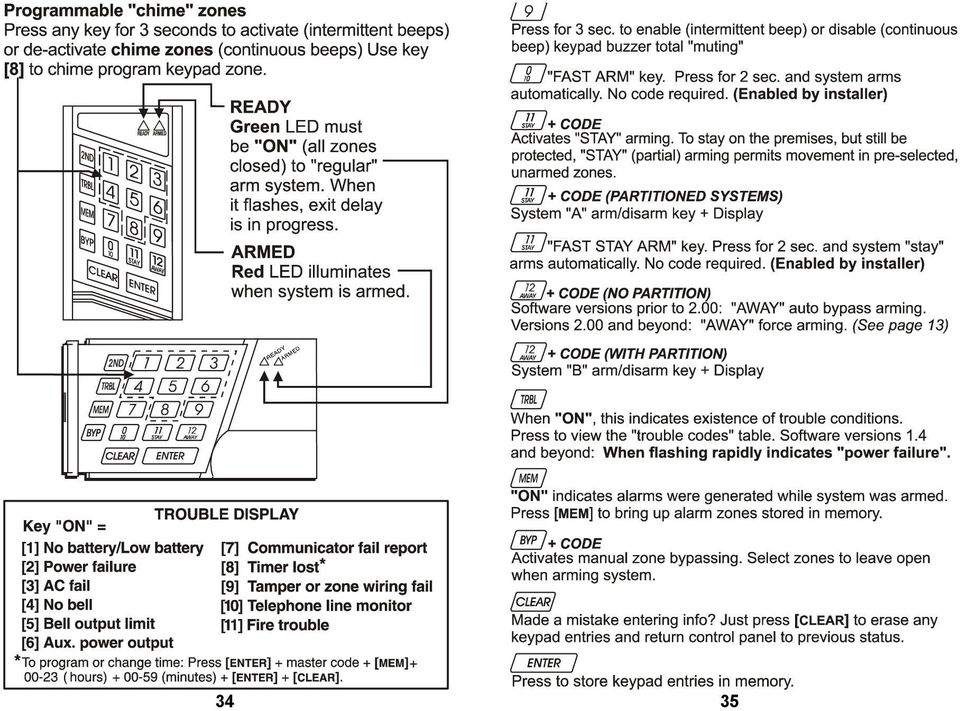
5 Each access code is made up of 4 or 6 digits (programmed by your installer). The master code and user codes are identified by a 2 digit "code number". CODE CODE # CODE CODE # CODE CODE # Master 00 User User User 1 01 User User User 2 02 User User User 3 03 User User User 4 04 User User User 5 05 User User User 6 06 User User User 7 07 User User User 8 08 User User User 9 09 User User User User User User User User User User User User User User User User User User User User User Creating User Codes: 1) Press [ENTER] + your master code or user 1 code. You will hear the CONFIRMATION beep and the [ENTER] key will flash, to show you that the panel is ready to accept your code number entries. 2) Enter the two digit "code number" (01-16, or 01-48) for the user code you wish to program (or 00 to change the master code). You will hear the CONFIRMATION beep, the [ENTER] key will stay on. 3) Key in 4 (or 6) digits of the user code number and press [ENTER]. The CONFIRMATION beep will be heard again. The [ENTER] key will flash. A four (or six) digit user code has been entered into memory. You may continue programming other user codes, or press [CLEAR] to exit programming mode. Note: [2ND] key flashes if location is empty (no code programmed). Duress code: (applicable for software version 3.10) The last user code (user 48) can be programmed to report a duress code. If you are forced to arm or disarm your system under threat, a duress code can be entered in the key sequence to produce a silent alarm at the monitoring station. Check with your installer to see if this option is active on your system. Deleting a user code: Pressing [ENTER] + master code + code location (01-48) to be erased + [2ND] key + [ENTER]. Press [CLEAR] to exit programming mode. (Note: Do not clear master code.) ARMING THE SYSTEM (without partitioning) The Esprit can be armed in 5 different ways designed to cover a wide variety of security situations. We suggest that you familiarize yourself with all 5 arming procedures so that you can take full advantage of your system. (1) REGULAR system arming (used for normal, day-to-day system operation) The keypad s green "READY" light must be on in 6 7
")
6 order to arm the system. This light will only illuminate if all zones are closed. All doors and windows must be closed, and there can be no movement in areas monitored by motion detectors. Once the "READY" light is on, enter your user code. If you make a mistake entering your code, the keypad sounder END/REJECTION beep will let you know. Just press [CLEAR] and re-enter the code. When you have correctly entered your user code, the red "ARMED" light will come on, and you will hear the keypad CONFIRMATION beep. The "READY" light will flash and the keypad will "beep" (if programmed) during the exit delay period. (Note: The last 10 seconds the beep will be faster.) [STAY] and [AWAY] keys will flash*. Your installer will program exit delay duration based on the time you require to safely exit the protected area once the system is armed. *On control panel models 728, 728 EXPRESS and 738 EXPRESS using software version 2.1X, keys indicated will not flash, but will be constantly illuminated. Software versions 2.2X onward, keys indicated do not illuminate. (2) STAY arming [STAY] + CODE OR KEY [11] (partial system arming) Stay arming allows you to remain in the protected area while partially arming the system. This means that you can stay in and move around your home, or commercial building, while certain designated zones are armed. You might choose to have entry/exit points like doors or windows protected, or the basement, or perhaps all the zones on the perimeter of your home or establishment. Based on your instructions, your installer programs the control panel to arm certain zones in Stay arming mode. These programmed Stay zones will arm on "Stay" mode and can only be changed by your installer. Please remember that fire zones cannot be bypassed. (Using this convenient feature, you can "Stay" arm the system and then leave the premises while others remain in the protected area.) Pressing [STAY] + ACCESS CODE (or KEY [STAY/11] - see below) on the keypad, activates Stay arming command. Stay arming can also be activated by a key switch - refer to key switch/push button arming. (3) ONE KEY arming (One touch system arming - no code required) KEY [10] regular arming When the "READY" light is on, pressing key [10] steadily for 2 seconds automatically "full" arms the system, if programmed. No user code is required. This feature can be used to allow specified individuals like service personnel (i.e. cleaners, maintenance) to arm the system when leaving the protected area, without giving them access to any other panel operations. KEY [STAY/11] Stay arming Please refer to Stay arming section above for a full explanation of this feature. There is no need to wait 8 9
 during the exit delay period. (Note: The last 10 seconds the beep will be faster.) [STAY] and [AWAY] keys will flash*.")
7 for the "READY" light before Stay arming, however all zones that have been programmed by your installer to arm in "Stay" mode, must be "closed" (no movement in the zones when arming the system). Pressing key [STAY/11] steadily for 2 seconds will automatically "Stay" arm the system. Double Stay arming: During the exit delay, pressing [STAY/11] again will switch any delay 1 or delay 2 zones to instant zones. 24 hour Stay zones, follow Stay zones, and instant Stay zones are not affected. Full system arming cancels double stay arming. Fast exit: Exit while the system is armed in Stay mode (key [STAY/11] is flashing*): A: fast exit and stay key [11]: To exit the premises and remain Stay armed, press key [STAY/11] for two seconds. The system will switch to exit delay mode ( READY LED flashes). At the end of the exit delay period, the system will return to Stay arming mode. B: fast exit and regular arm key [10] arm: Press key [10] for two seconds. The system will switch to regular arming (keys [11] and [12] flash*) with an exit delay ( READY LED flashes). At the end of the exit delay period, the system is regular armed. *On control panel models 728, 728 EXPRESS and 738 EXPRESS using software version 2.1X, keys indicated will not flash, but will be constantly illuminated. Software versions 2.2X onward, keys indicated do not illuminate. However, if system is Stay armed, [STAY] key will illuminate. Key switch/push-button Arming Your system can include a key switch or push button that arms/disarms the system. This arming method is particularly useful when installed in a master bedroom, making system arming and disarming convenient and accessible. The beautifully styled Esprit PS1 bedside remote has been specifically designed for this application and includes a panic zone. If an alarm is generated in your system, or a zone that has not been defined as a Stay zone is opened after panel arming, the system can only be disarmed from a keypad (if keyswitch is defined as "Stay" arming), using an access code. Please ask your installer for more information. (4) MANUAL BYPASS arming [BYP] + CODE (Arms the system while bypassing defective zones and/or zones you wish to leave open) Note: When you bypass a zone, it is no longer monitored by the security system. It will not generate an alarm on the control panel. You might not wish to arm the entire system when, for example, workers are renovating part of your 10 11
![Double Stay arming: During the exit delay, pressing [STAY/11] again will switch any delay 1 or delay 2 zones to instant zones.](/docs-images/49/16923063/images/page_7.jpg "24 hour Stay zones, follow Stay zones, and instant Stay zones are not affected. Full system arming cancels double stay arming.")
8 house, or for any other reason you need to leave a zone open. If a component of your security system is damaged, it can also be bypassed until repairs are made. Manual bypass arming instructs the control panel to ignore zones that you designate open, so that the rest of the system can still be armed. (Based on your instructions, only zones that your installer has programmed bypass-enabled can be bypassed during manual bypass arming, auto-bypass (Away) arming or Stay arming. Please note that the fire zone can not be bypassed.) Press the bypass [BYP] key, followed by your ACCESS CODE. You are now in bypass mode. The [BYP] key will be illuminated and if zones are currently bypassed they will illuminate as well. Enter the key numbers corresponding to the zones you wish to "bypass". Press again on the key if you wish to undo a zone selection. If you have entered the correct zone bypass information, press [ENTER]. The [BYP] key light will remain on indicating that zones have been bypassed. If you make an error entering zone numbers, press [CLEAR]. By using the bypass recall feature, you can reinstate the latest zone bypass instructions saved in memory. Press [BYP] while in manual bypass arming mode and the previous bypass status will be reestablished. This eliminates the need to enter the same "bypass" information every time you arm. (5) AUTO BYPASS (Away) arming [AWAY] + CODE Control panel software versions prior to 2.00: If you want to arm the system without manually entering zones to be bypassed on the keypad, use Away autobypass feature. [AWAY] + ACCESS CODE should be keyed in. The control panel will automatically bypass any open zones after the exit delay terminates and the system will be armed. The READY light does not have to be on, but all open zones must be bypass-enabled. If any zones have been left open, the [BYP] light will illuminate to indicate that zones have automatically been bypassed. (The fire zone cannot be bypassed.) FORCE (Away) arming [AWAY] + CODE Control panel software versions 2.00 and beyond: To arm the system rapidly without waiting for the READY light, use Force Away arming. [AWAY] should be pressed, followed by a valid access code. Once the exit delay expires, any open zones will not be considered activated by the panel. Open zones will not be protected, and will not generate an alarm or prevent arming. These Away zones will be activated (and therefore, protected) as soon as they are closed. Armed status is indicated by the [AWAY] key flashing*. (The fire zone cannot be force armed.) *On control panel models 728, 728 EXPRESS and 738 EXPRESS using software version 2.1X, key indicated will not flash, but will be constantly illuminated. Software versions 2.2X onward, key indicated does not illuminate. Control panel software versions prior to
 Press the bypass [BYP] key, followed by your ACCESS CODE. You are now in bypass mode.")
9 Note: These features are not recommended for regular use because leaving zones open can reduce the efficiency of system protection. (Force arming and auto bypass away arming are ideal for use with overhead garage doors!) "No movement" supervision feature Your panel can be programmed to send a report and/or arm the system if it is not armed (full or Stay arming ) and there is no zone activity for a preprogrammed amount of time. This is a particularly useful feature when supervising the elderly, individuals with chronic health problems or an individual that lives alone. Automatically Arm on Time Your installer can program your system to arm at a specific time each day. In this mode, all protected zones and detection devices must be in the "normal" state before arming can occur. Panic zones If you need to signal a panic situation, the Esprit provides three "panic" zones on your keypad. These panic zones must be programmed by your installer. Pressing keys [1] and [3] simultaneously for 2 sec. will generate a panic 1 or, if programmed, a panic alarm. Pressing keys [4] and [6] simultaneously for 2 sec. will generate a panic 2 or, if programmed, a auxiliary alarm. Pressing keys [7] and [9] simultaneously for 2 sec. will generate a "panic 3" or, if programmed, a "fire alarm". Based on your needs, your installer can program these panic zones to generate audible alarms (sirens or bells) or silent alarms, both of which also can be sent directly to your central security station. The 3 different panic zones can also communicate specific messages to your monitoring station, i.e. pressing panic 1 means "call the police", pressing panic 2 means "call an ambulance, pressing panic 3 means call the fire department". Ask your installer for the exact definition of your panel's panic alarms. DISARMING THE SYSTEM (without partitioning) Enter the area using the designated entry-exit door(s). The keypad sounder emits a constant tone to remind you to disarm your system. Enter your user code on the keypad before the entry time expires. If you make a mistake while entering this code, press [CLEAR] and re-enter it. The "ARMED" light will go off and the sounder will stop. SYSTEM ARMING/DISARMING (with partitioning) Zones can be divided into two systems. Based on your requirements, the installer designates which zones belong to "System A" or "System B", both systems (dual area), or are not given a system assignment (common area). A zone belonging to a dual area is armed if either System A or System B is armed, and disarmed only when both systems are disarmed. Control panel software versions 2.00 and beyond

10 A zone belonging to a common area is a zone that is armed only when both systems are armed, and disarmed if System A or System B is disarmed. Note: "System A" codes can stop sirens coming from "System B" zones (and vice versa), but will not disarm a system that is in alarm. Once zones have been assigned to either "System A" or "System B", code definition, also programmed by the installer, determines which access codes can arm "System A" zones, as well as which codes can arm "System B" zones. Codes can also be given access to both systems. When the "READY" light is on, entering a code that can access both systems will arm both "System A" and "System B. The [STAY] and [AWAY] keys will flash*, indicating the panel's armed status. Entering this code when the panel is armed will disarm both systems. To arm/disarm each system separately: Press [STAY] + a valid access code to arm/disarm "System A". (Valid access code = "System A" code, or code with access to both systems.) When the [STAY] key flashes*, this indicates System A's armed status. Press [AWAY] + a valid access code to arm/disarm "System B". (Valid access code = "System B" code, or code with access to both systems.) When the [AWAY] key flashes*, this indicates System B's armed status. *On control panel models 728, 728 EXPRESS and 738 EXPRESS using software versions 2.1X onward, keys indicated will not flash, but will be constantly illuminated. Pressing key [10] activates "one key" full arming. (When partitioning is enabled, System "A" and "B" will be armed when key [10] is pressed.) Pressing key [STAY/11] activates "one key" Stay arming. (When partitioning is enabled, System "A" is armed by pressing key [STAY/11].) PS1 Bedside remote module Pressing any one of the three keys of this module will arm or disarm the system in "Stay" mode (when partitioning is not activated). Please note that if the system is in entry delay or if an alarm is in progress, for your protection, the panel can only be disarmed from a keypad. Pressing any two PS1 keys simultaneously will generate a panic alarm. Your installer can also adjust the PS1's illumination level and mute the buzzer as required. Alarm Memory [MEM] The memory light [MEM] on your keypad will illuminate if any alarm situations take place while your system is armed. A record of all alarm situations that occur is stored in memory. After disarming the system, pressing once on the [MEM] key brings up the zones that were open during the last alarm period

11 Programmable output Not only does your Esprit control panel provide top security, it also offers you total convenience. Your installer can program the panel to reset smoke detectors & Glasstreks, to activate strobe lights, to activate light switches in your home or office, to reduce or increase building temperature, turn on/off air conditioning, open/close automatic garage doors, and more. Talk to your installer about this helpful feature! Keypad night illumination Pressing on the [MEM] key for 2 seconds changes it to the keypad illumination key. Pressing this key will then alter the illumination level from low, medium, to high, and then off. Keep pressing the [MEM] key until you reach the level you require, then press [ENTER] or [CLEAR] to save the setting in system memory. Chime zones Zones 1 to 6, as well as the local keypad zones, can be programmed as chime zones. A chime zone "advises" you when it is opened by creating a rapid intermittent beep tone. To turn on the "chime zone" feature, press on the selected zone key for three seconds until the intermittent chime beep is heard. This means that the chime feature has been activated. If a continuous beep is heard, this means that the chime is "off". (The keypad zone chime is enabled by pressing key [8].) If you have more than one keypad in your system, please "chime" program each keypad separately. Keypad chimes must be reprogrammed if the panel suffers total power loss. CHIME KEYS: Key [1]-[6] Turns chime "ON" or "OFF" in zones numbered 1-6. Key [8] Turns the chime "ON" and "OFF" for the zone connected to this keypad. Each keypad must be programmed independently. PANEL BUZZER MUTE: Key [9] Turns keypad sounder "ON" and "OFF" (intermittent beep means MUTE is activated, and keypad sounder is "OFF". Depress for 2 seconds to disable.) TROUBLE DISPLAY and TROUBLE MEMORY 10 different trouble conditions can be displayed on your keypad. When a trouble condition occurs, the [TRBL] key on your keypad illuminates and if programmed by your installer, the keypad sounder will beep. (When power supply failure trouble occurs, the [TRBL] key flashes rapidly. ) Press on this key and it flashes, indicating that your panel is in "trouble display" mode. Control panel software versions prior to 2.00: Keys that illuminate in "trouble display" mode tell you which trouble conditions are taking place and/or are Control panel software versions 2.00 and beyond

12 in memory. Pressing on any key except [2ND] will return the keypad to normal zone display. Trouble conditions will remain in "trouble" memory. Pressing on the [2ND] key displays current trouble conditions. Pressing [CLEAR] will erase trouble conditions in memory. Control panel software versions 2.00 and beyond: Keys that illuminate in trouble display mode indicate the trouble conditions currently taking place. Press on any key to return keypad to normal zone display. Key [1] No battery/low battery If battery is not connected to control panel, or if it is at low capacity, key [1] illuminates. This means that the battery connected to panel should be replaced because it can no longer provide adequate back-up current in the event of a power failure. Trouble indicator [1] will also illuminate if battery voltage drops to 10.5 volts while panel is running on battery power (with no AC). Key [2] Power failure (Control panel software versions 1.4 and beyond) If AC power is not being supplied to the panel and/or the power supply is unable to charge the battery and/or the power supply voltage exceeds 14.9 volts, key [2] will illuminate. Power failure can be excluded from key [TRBL] display by your installer. When a power supply failure trouble occurs, [TRBL] key flashes rapidly. Key [3] AC power failure (Control panel software versions prior to 1.4) If AC power is not being supplied to the control panel, key [3] will illuminate. AC trouble can be excluded from keypad "trouble display" by your alarm installer. Key [4] Bell disconnect If a bell or siren is not connected to the bell/siren output, this is indicated by the illumination of key [4] in trouble display mode. Key [5] Maximum bell current If key [5] illuminates, it indicates that the processor has recognized that the bell/siren output current exceeds 3A. This causes automatic shutdown of the bell output. Once the problem is corrected, power will automatically be restored to the bell/siren circuit. Key [6] Maximum auxiliary current Key [6] illumination indicates that the processor has recognized auxiliary output current exceeds 1A. This causes automatic shutdown of the auxiliary output. Once the problem is corrected, power will automatically be restored to the auxiliary output. This output powers such devices as motion detectors and accessory modules. Key [7] Communicator report failure If your control panel cannot communicate with the central monitoring station, key [7] illuminates

13 Key [8] Timer loss If the system timer is not functioning, usually after total battery and AC power failure, key [8] illuminates. The timer should be reprogrammed after total power loss. To reprogram the timer (control panel software versions prior to 2.00): Press [ENTER] + master code/user 1 code + [MEM]. Then enter 2 digits (00 to 23) for hours, followed by 2 digits (00 to 59) for minutes. Press [ENTER] twice. If trouble key [8] is still illuminated, press [TRBL] + [CLEAR] after programming the time. To reprogram the timer (control panel software versions 2.00 and beyond): Press [ENTER] + master code/user 1 code + [MEM]. Key [MEM] flashes. Then enter 2 digits (00 to 23) for hours, followed by 2 digits (00 to 59) for minutes. Press [ENTER]. Key [9] Tamper/zone wiring failure Key [9], if illuminated, means that there is a wiring problem in one of your protected zones. Key [10] Telephone line monitor Key [10] illuminates if the panel detects the loss of the telephone line. Key [11] Fire/trouble If the fire zone is cut, the fire zone key and trouble key [11] will illuminate. security company. Please make sure to contact your alarm company, however, to ensure that repairs are immediately made to your security system. Fire Alarm Operation Alarm Upon a Fire Alarm, the bell/siren will operate in "pulse mode". Silence/Reset To silence or reset a fire alarm, enter a valid user code. Note: IF A FIRE CONDITION EXISTS, FOLLOW YOUR EVACUATION PLAN IMMEDIATELY! If there is no fire condition, contact your monitoring company without delay to avoid an unnecessary response. Fire Safety in the Home Reasonable fire safety can be achieved by following a three point program: 1. Minimizing fire hazards 2. Providing a fire warning system 3. Having and practicing an escape plan Minimizing Fire Hazards The three traditional fire killers are: 1. Smoking in bed 2. Leaving children home alone 3. Cleaning with flammable liquids such as gasoline Most of these "trouble" conditions will be programmed by your installer to be reported directly to your 22 23
![Then enter 2 digits (00 to 23) for hours, followed by 2 digits (00 to 59) for minutes. Press [ENTER] twice. If trouble key [8] is still illuminated, press [TRBL] + [CLEAR] after programming the time.](/docs-images/49/16923063/images/page_13.jpg "To reprogram the timer (control panel software versions 2.00 and beyond): Press [ENTER] + master code/user 1 code + [MEM]. Key [MEM] flashes.")
14 Providing a Fire Warning System Household fires are especially dangerous at night. Fires produce smoke and deadly gases that can overcome occupants while they sleep. To warn against fire, smoke detectors should be installed outside of each separate sleeping area in the immediate vicinity of the bedrooms and on each additional story of the family living unit, including basements. Having and Practicing an Escape Plan There often may be very little time between detection of a fire and the time that it becomes deadly. This interval may be as little as one or two minutes. Advance warning of a fire may be wasted unless the family has planned in advance for a rapid exit from their residence. Notes: 1. Plan and practice for fire conditions with the focus on rapid exit from the residence. 2. Drills should be held so that all family members know what to do. 3. Each person should plan for the possibility that an exit out of the bedroom window may be necessary. An exit out of the residence that does not require the opening of a bedroom door is essential. Provision for the Disabled For special circumstances where life-safety of some occupant(s) depends upon prompt rescue by others, the fire warning system includes a means of prompt, automatic notification to those who are to be depended upon for the rescue. Testing your System It is recommend that your system be tested once a week. Contact your monitoring station BEFORE and AFTER testing. Burglar Alarm Testing With the system disarmed and the READY light on, activate motion detectors (walk in protected area). Open and close protected doors. Observe the zone light. It should come on following each activation. If keypad panic keys are enabled (check with your installer), pushing one of these keys will initiate a local alarm (if programmed) and a signal to be transmitted to the monitoring station (if programmed). Your installer can advise you of the best way to test your particular system. Fire Alarm Testing CAUTION: Do not use open flame or burning materials to test your fire detection devices. Contact your alarm installer to discuss safe methods to test your system. System Maintenance Under normal use, your system requires virtually no maintenance other than regular testing. It is recommended that the standby battery be changed every three years

15 KEY ACCESS PROGRAMMING Several control panel features can be programmed quickly on the keypad, without entering any programming addresses or section numbers. Select one-key access programming mode by pressing [ENTER], followed by master or user code 1. Then press the single key (listed below) corresponding to the feature you wish to activate. (Verify first with your installer that all of the features listed below have been programmed and activated on your control panel. Press [ENTER] or [CLEAR] to exit. key [9] "Auto arming" time program Key [9] flashes. Enter two digits (00 to 23) for hours + 2 digits (00 to 59) for minutes. (Press [ENTER].) [TRBL] Call Espload via telephone If programmed by your installer, this initiates communication to the central monitoring station computer using Espload software. [AWAY] Answer Espload This feature initiates modem communication between your panel and a computer running Espload software. (The ADP-1 adapter can also be used.) [STAY] Cancel communication attempts Stops calls from/to Espload. When communicating with Espload, it is impossible to enter programming mode. [MEM] "Panel time" Key [MEM] flashes. Enter two digits (00 to 23) for hours + 2 digits (00 to 59) for minutes. (Press [ENTER].) [BYP] Test report If programmed by your installer, this sends a test report code to the monitoring station. Control panel software versions 2.00 and beyond. Control panel software versions prior to
![(Verify first with your installer that all of the features listed below have been programmed and activated on your control panel. Press [ENTER] or [CLEAR] to exit.](/docs-images/49/16923063/images/page_15.jpg "key [9] \"Auto arming\" time program Key [9] flashes. Enter two digits (00 to 23) for hours + 2 digits (00 to 59) for minutes. (Press [ENTER].")
16 IMPORTANT: Keep this information in a secure location. ZONE DESCRIPTION PARTITIONING Yes No SYSTEM 24 Bypass ACTIVATED A B Hr Enabled Zone 1: Zone 2: Zone 3: Zone 4: Zone 5: Zone 6: Zone 7: Zone 8: Zone 9: Zone 10: Zone 11: ZONE DESCRIPTION PARTITIONING Yes No SYSTEM 24 Bypass ACTIVATED A B Hr Enabled Zone 13: Zone 14: Zone 15: Zone 16: Zone 17: Zone 18: Zone 19: Zone 20: Zone 21: Zone 22: Zone 23: Zone 24: Zone 12: 28 29

17 ACCESS CODES Name Code Arming Priority Name Code Arming Priority Reg. Stay Away Byp A B 4 digit 6 digit Reg. Stay Away Byp A B User 24 Master 00 User 25 User 01 User 26 User 02 User 27 User 03 User 28 User 04 User 29 User 05 User 30 User 06 User 31 User 32 User 07 User 33 User 08 User 34 User 09 User 35 User 10 User 36 User 11 User 37 User 12 User 38 User 13 User 39 User 14 User 40 User 15 User 41 User 16 User 42 User 42 User 17 User 43 User 18 User 44 User 19 User 45 User 20 User 46 User 21 User 47 User 22 User 48 User 23 NOTE: FOR SECURITY REASONS WRITE ONLY USER NAMES AND NOT ACTUAL ACCESS CODES! 30 31

18 SPECIAL KEYS AND FUNCTIONS Key [10] Regular arming is activated. Key [STAY/11] Stay arming is activated (Arms system A only, when partitioning is enabled) [1] and [3]* Police or Silent Audible Not Used [4] and [6]* Auxiliary or Silent Audible Not Used [7] and [9]* Fire or Silent Audible Not Used *Both keys must be depressed at the same time for 2 seconds - Armed LED will flash. The PGM (Programmable Output) function (if applicable), is and is activated by. SYSTEM TIMES Entering and exiting your premises is permitted through doors that you and your installer have determined. You have one exit time and up to two individual entry times i.e. Zone 1-Front door delay 1 (30 sec), Zone 7-Garage door delay 2 (90 sec). You have Your Entry delay 1 is seconds and you may enter through zone #. Your Entry delay 2 is seconds and you may enter through zone #. Your siren, if activated by an alarm, will sound for minutes. OTHER INFORMATION This alarm system was installed on: By:. Service is provided by Tel:. Your monitoring station's telephone number is:. Your account number is:. Your alarm transformer location is is on circuit #. seconds to EXIT your premises and UL verified compatibility of the with Esprit models 708, 728, 728 EXPRESS, 738, 738 EXPRESS, 748, 748ES and SRI-18. Look for and marks on products. Only products bearing those marks are UL and ULC listed.
, Zone 7-Garage door delay 2 (90 sec).")
19 34 35
20 WARRANTY The Seller warrants its products to be free from defects in materials and workmanship under normal use for a period of one year. Except as specifically stated herein, all express or implied warranties whatsoever, statutory or otherwise, including without limitation, any implied warranty of merchantability and fitness for a particular purpose, are expressly excluded. Because Seller does not install or connect the products and because the products may be used in conjunction with products not manufactured by Seller. Seller cannot guarantee the performance of the security system. Seller obligation and liability under this warranty is expressly limited to repairing or replacing, at Seller's option, any product not meeting the specifications. In no event shall the Seller be liable to the buyer or any other person for any loss or damages whether direct or indirect or consequential or incidental, including without limitation, any damages for lost profits stolen goods, or claims by any other party, caused by defective goods or otherwise arising from the improper, incorrect or otherwise faulty installation or use of the merchandise sold. Paradox Security Systems - Graphic Dept.

616, 626, 636 & 646 Keypads
 616, 626, 636 & 646 Keypads User s Manual TABLE OF CONTENTS 1.0 BASIC OPERATION...2 2.0 ACCESS CODES...4 3.0 ARMING & DISARMING...6 4.0 PANIC ZONES...13 5.0 KEY ACCESS PROGRAMMING.14 6.0 ADDITIONAL FEATURES...15
642 LCD Keypad User Manual
 642 LCD Keypad User Manual TABLE OF CONTENTS Introduction...3 Legend... 3 Basic Operation...5 Keypad Indicator Lights... 5 Visual Feedback... 5 Auditory Feedback... 6 Info List... 7 Access Codes...8 User
LCD and 16-Zone LED Keypads. User s Manual
 LCD and 16-Zone LED Keypads 1689 1641 16-Zone LED Keypad LCD Keypad User s Manual TABLE OF CONTENTS 1.0 INTRODUCTION...3 2.0 BASIC OPERATION...4 2.1 Keypad Indicator Lights... 4 2.2 Visual Feedback...
10-Zone Spectra LED Keypads
 10-Zone Spectra LED Keypads 1686V 1686H User s Guide We hope this product performs to your complete satisfaction. Should you have any questions or comments, please visit www.paradox.com and send us your
Digiplex LCD Keypad DGP-641. User s Manual
 Digiplex LCD Keypad DGP-641 User s Manual TABLE OF CONTENTS 1.0 INTRODUCTION... 7 1.1 Legend... 7 2.0 BASIC OPERATION... 8 2.1 Auditory Feedback (Beep Tones)... 9 2.2 Keypad Indicator Lights... 9 2.3
Digiplex LCD Keypad DGP-641. User s Manual
 Digiplex LCD Keypad DGP-641 User s Manual 1.0 TABLE OF CONTENTS INTRODUCTION...6 1.1 Legend... 6 BASIC OPERATION... 7 2.1 Auditory Feedback (Beep Tones)... 8 2.2 Keypad Indicator Lights... 8 2.3 LCD Screen...
Users Guide to Keypad Functions
 Users Guide to Keypad Functions MANUAL NO. 700-175-01J ISSUED JAN 2002 VERSION 1.41 Summary of Operation A rm/ disarm [#] + [USER CODE] Quick Quick Quick Panic Fire Medical Away Arm Stay Arm Stay Arm &
IDS. Users Guide to Keypad Functions S E C U R I T Y MANUAL NO. 700-171-01B ISSUED AUG 2002 VERSION 1.18
 INHEP DIGITAL IDS S E C U R I T Y Users Guide to Keypad Functions MANUAL NO. 700-171-01B ISSUED AUG 2002 VERSION 1.18 Summary of Operation A rm/ disarm [#] + [USER CODE] Quick Quick Quick Away Arm Stay
EVO48 EVO192. User Guide
 EVO48 EVO192 User Guide We hope this product performs to your complete satisfaction. Should you have any questions or comments, please visit www.paradox.com and send us your comments. Table of Contents
CONTENTS 4. HOW TO UNSET THE PANEL...7
 Pi-8 USER MANUAL CONTENTS 1. THE KEYPAD AND ITS OPERATION...3 1.1 DESCRIPTION OF THE KEYPAD LEDS... 3 1.1.1 READY LED (RED)...3 1.1.2 TAMPER LED (RED)...3 1.1.3 POWER LED (GREEN)...3 1.1.4 CIRCUIT LEDs
SPECIAL CODES AUXILIARY CODES SYSTEM NOTES
 Installing/Service Company Monitoring Center SPECIAL CODES Master Code Duress Code AUXILIARY CODES "Quick Arm" " Chime" 08 02 09 03 10 04 11 05 12 06 13 07 14 SYSTEM NOTES Exit Delay Time Entry Delay Time
Using your LED Plus keypad
 Using your LED Plus keypad System 238 System 2316 System 238i System 2316i Part Number 5-051-372-00 Rev B Thank you for purchasing this C&K alarm system Your system is one of the most powerful and advanced
System Manager s Manual
 LCD Keypad DGP2-641B / DGP2-641RB DGP2-641 / DGP2-641R System Manager s Manual Also includes Operating Instructions Table of Contents Introduction... 1 Legend... 1 Basic Operation... 1 Auditory Feedback
INSTRUCTION MANUAL LCD-6OO SECURITY STATION
 INSTRUCTION MANUAL 1993 Digital Security Controls Ltd. 1645 Flint Road, Downsview, Ontario, Canada M3J 2J6 Printed in Canada 29000144 R1 LCD-6OO SECURITY STATION Table of Contents Introduction 1 About
FIRST ALERT INSTRUCTION MANUAL FOR FA 270 KEYPADS SECURITY SYSTEM
 FIRST ALERT INSTRUCTION MANUAL FOR FA 270 KEYPADS SECURITY SYSTEM Page 0 Table of Contents Introduction 1 System Basics.. 1 Burglary Protection.. 1 Fire Protection.. 1 Security Codes. 1 Zones and Partitions
SECURITY SYSTEM NOTES. Security System Configuration
 Installing / Service Company: For Service Call: SECURITY SYSTEM NOTES Security System Configuration Master Code: Auxiliary Code(s) 2 3 4 5 6 "Quick Arm" Digit: Exit Delay Time Auxiliary Exit Delay Time
SECURITY SYSTEM NOTES SPECIAL CODES. Security System Configuration
 Installing / Service Company: SECURITY SYSTEM NOTES For Service Call: Master Code SPECIAL CODES Duress Code Security System Configuration Auxiliary Code(s) Quick Arm" Digit: 2 9 3 10 4 11 5 12 6 13 7 14
Always Armed, Never Disarmed User Guide
 E55 E65 Always Armed, Never Disarmed User Guide Warranty For complete warranty information on this product please refer to the Limited Warranty Statement found on the website www.paradox.com/terms. Your
HILLS Series LED Code Pad User Manual
 HILLS Series LED Code Pad User Manual Not all features may be available on your system Check with your installer to find out which features are programmed Page 2 TABLE OF CONTENTS Code Pad Diagrams...2
National Security Systems Inc (800)457-1999. Security System User's Guide
457-1999. Security System User's Guide") National Security Systems Inc (800)457-1999 Security System User's Guide Security System Glossary As security system technology has evolved, a special jargon has developed. Some terms widely used within
National Security Systems Inc (800)457-1999 Security System User's Guide Security System Glossary As security system technology has evolved, a special jargon has developed. Some terms widely used within
SECURITY SYSTEM NOTES
 SECURITY SYSTEM NOTES Installing/Service Company For Service Call Central Station Duress Code FUNCTION CODES Function Code Controls Function EMERGENCY ACTIVATION KEYS (check if enabled) Fire Auxiliary
INSTRUCTION MANUAL PC255O
 INSTRUCTION MANUAL PC255O Canadian Department of Communications Notice NOTICE: The Canadian Department of Communications label identifies certified equipment. This certification means that the equipment
SECURITY SYSTEM NOTES
 SECURITY SYSTEM NOTES Installing/Service Company For Service Call Central Station Duress Code FUNCTION CODES Function Code Controls Function This system is is not partitioned. EMERGENCY ACTIVATION KEYS
IDS X-Series User Manual 700-398-01D Issued July 2012
 1 2 Contents 1. Introduction to the IDS X-Series Panels... 7 2. Before Operating Your Alarm System... 7 3. Understanding the Keypad LEDs... 8 3.1 Viewing Data on an LED Keypad... 12 3.1.1 LED Status Indicators...
SECURITY SYSTEM NOTES SPECIAL CODES AUXILIARY ARM / DISARM CODES ENTRY / EXIT DELAY TIMES ZONE DESCRIPTIONS
 SECURITY SYSTEM NOTES Installing/Service Company For Service Call SPECIAL CODES Master Code Duress Code "Quick Arm" Digit "Chime" Digit "Entry-Guard" Digit AUXILIARY ARM / DISARM CODES 02 12 22 03 13 23
NetworX Series. NX- 4/8 Code Pad. User Manual (Australian Version)
") NetworX Series NX- 4/8 Code Pad User Manual (Australian Version) Table Of Contents Code Pad Diagram... Inside Front Glossary of Terms...2 Understanding the Code Pad lights...3 Code Pad Tones...4 Fully
NetworX Series NX- 4/8 Code Pad User Manual (Australian Version) Table Of Contents Code Pad Diagram... Inside Front Glossary of Terms...2 Understanding the Code Pad lights...3 Code Pad Tones...4 Fully
User s Guide. Security Systems D220
 User s Guide Security Systems D220 Table of Contents About This User s Guide... 3 Introduction... 3 Security System Basics... 4 Controlled Points... 5 24-Hour Points... 6 Keypad Keys... 6 Keypad Lights...
Solution-16 Operators Manual ISSUE 1.60
 Solution-16 Operators Manual ISSUE 1.60 !"#$%&"'()*+ Operators Manual Copyright 2002 by, SYDNEY, AUSTRALIA Document Part Number MA880O DOCUMENT ISSUE 1.60 Printed 22 March 2002 This documentation is provided
SECURITY SYSTEM NOTES SPECIAL CODES ENTRY / EXIT DELAY TIMES ARM / DISARM CODES
 SECURITY SYSTEM NOTES Installing/Service Company For Service Call SPECIAL CODES "Chime" Digit 1 "Partial Arm" Digit 2 "Quick Arm" Digit 3 ENTRY / EXIT DELAY TIMES Exit Delay Time Entry Delay Time Secondary
Understanding the Code Pad lights...4. Code Pad tones...5. Fully arming the system On MODE...6. Fully arming the system - Quick Arm MODE...
 TABLE OF CONTENTS...Glossary of terms...2...code Pad Diagram...3 Understanding the Code Pad lights...4 Code Pad tones...5 Fully arming the system On MODE...6 Fully arming the system - Quick Arm MODE...6
SECURITY SYSTEM NOTES AREA LISTINGS SPECIAL CODES ENTRY / EXIT DELAY TIMES ARM / DISARM CODES ZONE DESCRIPTIONS
 SECURITY SYSTEM NOTES Installing/Service Company For Service Call Area 1 Area 2 Area 3 AREA LISTINGS SPECIAL CODES "Quick Arm" Digit "Partial Arm" Digit "Chime" Digit ENTRY / EXIT DELAY TIMES Exit Delay
HILLS Series LED Code Pad User Manual
 HILLS Series LED Code Pad User Manual Not all features may be available on your system Check with your installer to find out which features are programmed Page 2 TABLE OF CONTENTS Code Pad Diagrams...2
PowerWave-8. Users Operating and Programming Guide Version 8.64. 8 zone Control panel Communicator
 ELECTRONIC ENGINEERING LTD. PowerWave-8 8 zone Control panel Communicator Users Operating and Programming Guide Version 8.64 P/N 7101261 Rev. C N.A July 2002 2 Contents Introduction...5 Meet the Crow Alarm
NetworX NX-6V2. LED Keypad User Manual
 NetworX NX-6V2 LED Keypad User Manual POWER Light is on when AC power is present; flashes to indicate a low battery condition. ARMED Light is on when armed; off when disarmed; flashes to indicate a previous
SCORPION Z16040C Alarm Controller User Instructions
 SCORPION Z16040C Alarm Controller User Instructions Thank you for choosing to purchase this micron security alarm controller. Micron product is manufactured to exacting quality standards. We understand
System Manager s Manual for DGP-848 Systems
 LCD Keypad Module DGP2-641/DGP2-641R DGP2-641BL/DGP2-641RB System Manager s Manual for DGP-848 Systems Also includes Operating Instructions Table of Contents Introduction... 1 Legend... 1 Basic Operation...
SECURITY SYSTEM NOTES. EMERGENCY ACTIVATION KEYS (check if enabled) PROGRAMMED FUNCTIONS
 PROGRAMMED FUNCTIONS") SECURITY SYSTEM NOTES Installing/Service Company For Service Call Installation Date / / Central Station Duress Code EMERGENCY ACTIVATION KEYS (check if enabled) Fire Auxiliary Emergency Police PROGRAMMED
SECURITY SYSTEM NOTES Installing/Service Company For Service Call Installation Date / / Central Station Duress Code EMERGENCY ACTIVATION KEYS (check if enabled) Fire Auxiliary Emergency Police PROGRAMMED
MONITOR ISM / AFx Multi-Tenant Security System User Guide V1.3
 MONITOR ISM / AFx Multi-Tenant Security System User Guide V.3 Multi-Tenant Security System User Guide Welcome New Users! There are two types of suite security keypads. Follow the instructions in the proceeding
INSTRUCTION MANUAL PC5OO WITH PC5OORK KEYPAD
 INSTRUCTION MANUAL PC5OO WITH PC5OORK KEYPAD TABLE OF CONTENTS SYSTEM INFORMATION 2 INTRODUCTION 3 Test Your System Regularly...3 Important Notice...3 Glossary...3 BASIC OPERATION 4 Arming Your System...4
www.ealarm.com.my P/N 5-051-371-00 Rev D
 System 236 System 236i P/N 5-051-371-00 Rev D Thank you for purchasing this C&K alarm system Your system is one of the most powerful and advanced alarm systems on the market today, designed to provide
Solution 862 Operators Manual. Issue 1.00
 Solution 862 Operators Manual Issue 1.00 Solution 862 Operators Manual Copyright 1998 by Electronics Design and Manufacturing Pty Limited, SYDNEY, AUSTRALIA Document Part Number MA406O Document Issue
User Guide for the DS7060 Control/Communicator
 DS7060 User Guide Copyright 1996-97 Detection Systems, Inc. User Guide for the DS7060 Control/Communicator Copyright 1996-97 Detection Systems, Inc. Detection Systems, Inc., 130 Perinton Parkway, Fairport,
HARDWIRED CONTROL PANELS
 USER GUIDE 9651 HARDWIRED CONTROL PANELS Contents 1. Introduction...3 The Alarm System...3 The Keypad...3 About This Guide...5 2. Everyday Operation...6 How Do I Know if the System is Working?...6 Setting
GE Concord 4 Quick User Guide
 GE Concord 4 Quick User Guide GE Concord 4 Quick User Guide Page 1 Before Calling Is the keypad beeping? Press *. This will silence the beeping and let you know where the trouble is. Is there a flashing
MG5000 MG5050 SP65 SP4000 SP5500 SP6000 SP7000. User Guide. Always Armed, Never Disarmed
 MG5000 MG5050 SP65 SP4000 SP5500 SP6000 SP7000 Always Armed, Never Disarmed User Guide Warranty For complete warranty information on this product please refer to the Limited Warranty Statement found on
User s Guide. Security Systems
 User s Guide Security Systems National Security Systems Inc (800)457-1999 2 Table of Contents About This Users Guide... 4 Introduction... 4 Security System Basics... 5 Controlled Points... 6 24-Hour Points...
User s Guide. Security Systems
 User s Guide Security Systems 2 Table of Contents About This Users Guide... 4 Introduction... 4 Security System Basics... 5 Controlled Points... 6 24-Hour Points... 7 Keypad Keys... 7 Keypad Tones... 8
Vision Security System OWNER MANUAL V-LCD1
 Vision Security System OWNER MANUAL V-LCD1 Congratulations on your purchase of the OPTEX Vision security system. Vision is an advanced microprocessor based alarm system which provides fire and burglar
astec Integrated Alarm System USER GUIDE
 astec Integrated Alarm System USER GUIDE 020008599 CONTENTS Full Set, Part Set and Disarm 3 Instant Full Set 3 Part Set with exit time 4 Bell Test 4 Bypassing zones 4 Switch Lights on/off 4 Bypass (24
Solution 880 Operators Manual ISSUE 1.10
 Solution 880 Operators Manual ISSUE 1.10 Solution 880 Operators Manual Copyright 2001 by, SYDNEY, AUSTRALIA Document Part Number MA408O DOCUMENT ISSUE 1.10 Printed 25 May 2001 This documentation is provided
User s Information Guide R1A
 HSC505-R Home Security Controller - User Manual Release R1a Pi HSC505 and Pi HSC505R Home Security Controller User s Information Guide R1A Page 1 QD Dynamics (Pty) Ltd reserves the right to make changes
Security System. User's Guide. Keypad
 Security System EN User's Guide Keypad Security System User's Guide This system includes a telephone line seizure feature. The system can be programmed to communicate with a central monitoring station
VISTA-128FBP VISTA-250FBP Commercial Fire and Burglary Partitioned Security Systems with Scheduling
 VISTA-128FBP VISTA-250FBP Commercial Fire and Burglary Partitioned Security Systems with Scheduling User Guide K0377V2 7/09 Rev. C 2 TABLE OF CONTENTS SYSTEM OVERVIEW... 5 General... 5 A Partitioned System...
ICP-CC488. Installation Guide ICP-CC488 Control Panel
 ICP-CC488 EN Installation Guide ICP-CC488 Control Panel ICP-CC488 Installation Guide Notices EN 2 Copyright Notice Unless otherwise indicated, this publication is the copyright of Bosch Security Systems,
USER GUIDE SERIES 4250 AUDIO ALARM CONFIRMATION SYSTEM CONTROL UNIT
 USER GUIDE SERIES 4250 AUDIO ALARM CONFIRMATION SYSTEM CONTROL UNIT CONTENTS Page INTRODUCTION... 2 Security conditions... 3 Full Set (Fully armed)... 3 Part Set (Partially armed)... 3 Unset (Disarmed)...
http://www.ealarm.com.my
 MG5000 MG5050 SP5500 SP6000 SP7000 Always Armed, Never Disarmed User Guide Warranty For complete warranty information on this product please refer to the Limited Warranty Statement found on the website
CONTENTS QUICK SETUP & INSTALLATION USER MANUAL. SUPA8 Quick Setup & User Manual
 SUPA8 Quick Setup & User Manual QUICK SETUP & INSTALLATION CONTENTS FACTORY DEFAULTS... 1 INSTALLATION OF THE SECURITY SYSTEM... 2 COMMISSIONING THE DIALLER PANEL... 5 ZONE INPUT CONNECTIONS... 7 PANEL
INSTALLATION MANUAL PC2525. Version 1.1
 INSTALLATION MANUAL PC2525 Version 1.1 TABLE OF CONTENTS FEATURES 1 SPECIFICATIONS 1 INSTALLATION 2 Mounting the Panel... 2 Mounting the Keypad... 2 Auxiliary Power Connection... 2 Bell/Siren Connection...
Wireless Home Security System Product Manual (Model #80355)
") Wireless Home Security System Product Manual (Model #80355) Installation Instructions During set-up, if no key is pressed for 15 seconds it will come out of the setup mode and you will have to start over.
Wireless Home Security System Product Manual (Model #80355) Installation Instructions During set-up, if no key is pressed for 15 seconds it will come out of the setup mode and you will have to start over.
HUNTER-PRO 32 Ver. 3.8 Intruder Alarm System RXN-9/416 User Guide
 HUNTER-PRO 32 Ver. 3.8 Intruder Alarm System RXN-9/416 User Guide PIMA Electronic Systems Ltd. 5 Hatzoref Street, Holon 58856, Israel +972-3-5587722 +972-3-5500442 [email protected] http://www.pima-alarms.com
Contents 1. Terms you may neeed to know 2. Keypad Lights 3, 4. Keypad Buttons 5
 Security Alarm System Owner's Guide 8 sector CDS Dialler Version 2.0 lcopm.pm6 Contents Contents 1 Terms you may neeed to know 2 Keypad Lights 3, 4 Keypad Buttons 5 User Functions Fully Arming the System
NESS D16. 16 Zone Control Panel and Dialler OWNER S MANUAL
 NESS D16 16 Zone Control Panel and Dialler OWNER S MANUAL REVISION 2, JULY 2001 Ness Security Products Pty Ltd Quality Endorsed Company ISO9001 LIC.No. QEC2074 NSW Head Office only WWW.NESS.COM.AU Australia
TABLE OF CONTENTS FEATURES
 TABLE OF CONTENTS FEATURES 2 Keypad Programmable... 2 EEPROM Memory... 2 Static/Lightning Protection... 2 Supervision... 2 Operation... 2 SPECIFICATIONS 2 PC1550 Control Panel... 2 PC1500RK Keypad... 2
Using Your GEM-P400 Security System
 Using Your GEM-P400 Security System ARMED GEMINI STATUS 1 2 3 4 &20387(5,=(' 6(&85,7< 6
SCORPION. micron security products
 SCORPION 4120 6020 & 8020 USER INSTRUCTIONS Thank you for purchasing a Quality Micron Security Alarm Controller. Micron product is manufactured to exacting quality standards. We understand the importance
Intruder alarm system Operating Instructions
 New remote keypad Intruder alarm system Operating Instructions 0 2 3 4 5 6 7 8 9 CHIME OMIT RESET PROG SET Power Power 0 2 3 5 6 7 8 Chime Omit Prog 4 9 Set AccentaG3 mini Servicing organisation details
2 4PI175 issue 1_6/01. How to unset system in alarm. Programs 1, 2 and 3. Access codes. How to operate Personal Attack
 Access codes Contents Unset system indications - - - - - - - - - - - System indication - - - - - - - - - - - - Access codes - - - - - - - - - - - - - - - - How to operate Personal - - - - - - How to unset
User's Manual 5120XM N8031 6/96
 Fire and Burglary System User's Manual 5120XM N8031 6/96 SYSTEM OVERVIEW...3 General...3 Zones...3 Fire & Emergency Protection...3 Burglary Protection...4 Alarms...4 Memory of Alarm...4 ABOUT THE KEYPADS...5
Ademco Vista-20P/First Alert FA-168C Basic Commands
 Zones 64 total Ademco Vista-20P/First Alert FA-168C Basic Commands Wireless Yes, Zones 09 to 48 + 16 Keyfob Zones (Zones 49 to 64) Batteries Downloadable Partitions 2 12 volt Rechargable inside main Panel,
GC2 Panel User Guide
 GC2 Panel User Guide ENGLISH (International) WIRELESS SECURITY SYSTEM WARNING: OWNER S I NSTRUCTION NOTICE Not to be removed by anyone except occupant THIS PAGE INTENTIONALLY LEFT BLANK CONTENTS System
How To Set A Timer On A Gg System
 ZONE ZONE 2 ZONE ZONE ZONE 5 ZONE 6 ZONE 7 ZONE Power PA XR2/ XR2+ Intruder alarm system Operating Instructions ZONE ZONE 2 ZONE ZONE ZONE 5 ZONE 6 ZONE 7 ZONE 0 2 5 6 7 9 Omit Prog Remote LED keypad 0
SECURIT 800L+ CONTROL PANEL
 USER MANUAL SECURIT 800L+ CONTROL PANEL COMPANY PROFILE IntelliSense have been successfully making security products for over 20 years and lead the security industry throughout the world with many innovative
500r+ Installation and User Guide
 500r+ Installation and User Guide Compatible Equipment 502rUK-50 Watch/Pendant PA. 509rUK-50 Smoke Detector 515rUK-00 10 metre passive infra red movement detector. 525rUK-00 Remote Set/Unset (Full and
D1260/D1260B. Keypad. National Security Systems Inc (800)457-1999. Owner's Manual
457-1999. Owner's Manual") D1260/D1260B EN Owner's Manual Keypad National Security Systems Inc (800)457-1999 D1260/D1260B Owner's Manual This system includes a telephone line seizure feature. The system may be programmed to communicate
D1260/D1260B EN Owner's Manual Keypad National Security Systems Inc (800)457-1999 D1260/D1260B Owner's Manual This system includes a telephone line seizure feature. The system may be programmed to communicate
Destiny 4100. Destiny 4100. Owners Manual
 Destiny 4100 Destiny 4100 Owners Manual TABLE OF CONTENTS INTRODUCTION Control Panel...3 Detection Devices...3 Telephone Keypads...3 GLOSSARY... 4-5 LOCAL PHONE ACCESS Using Your Telephones As Keypads...6
IMPORTANT See last page for changes from VERSION 1.2. To enter programming, press [ENTER] + installer code (Installer default code 747474)
![IMPORTANT See last page for changes from VERSION 1.2. To enter programming, press [ENTER] + installer code (Installer default code 747474)](/thumbs/39/18360179.jpg "IMPORTANT See last page for changes from VERSION 1.2. To enter programming, press [ENTER] + installer code (Installer default code 747474)") SOFTWARE VERSION 1.3 IMPTANT See last page for changes from VERSION 1.2 To enter programming, press [ENTER] + installer code (Installer default code 747474) ADDRESSES: addresses "000" to "255" ( key [10]
SOFTWARE VERSION 1.3 IMPTANT See last page for changes from VERSION 1.2 To enter programming, press [ENTER] + installer code (Installer default code 747474) ADDRESSES: addresses "000" to "255" ( key [10]
Maintenance Manual PC6010. WARNING This manual contains information on limitations regarding product use and function
 WARNING This manual contains information on limitations regarding product use and function and information on the limitations as to liability of the manufacturer. The entire manual should be carefully
D24 ALARM CONTROL PANEL USER S MANUAL REVISION 1.1 A$12.00 INC GST
 D24 ALARM CONTROL PANEL USER S MANUAL REVISION 1.1 A$12.00 INC GST Ness Security Products Pty Ltd Quality Endorsed Company ISO9001 LIC.No. QEC2074 NSW Head Office only WWW.NESS.COM.AU Australia s largest
Solution-16 Operators Manual ISSUE 1.40
 Solution-16 Operators Manual ISSUE 1.40 Solution-16 Operators Manual Copyright 1995-97 by, SYDNEY, AUSTRALIA Document Part Number MA880O Document Issue 1.40 Printed 29 July 1997 This documentation is
Elite 8D/Lite Version 8 Zone Controller. Arrowhead Alarm Products Ltd. Operating Guide. Proudly Designed and Manufactured in New Zealand
 Elite 8D/Lite Version 8 Zone Controller 8 Arrowhead Alarm Products Ltd Operating Guide 1 Proudly Designed and Manufactured in New Zealand 2 CONTENTS Page No. INTRODUCTION 4 About your Alarm 4 OPERATING
Using Your. Security System With Icon Keypad S5020, S5021, S5022
 Using Your Security System With Icon Keypad S5020, S5021, S5022 Contents 1 Overview Your Security System... 1 How Your Security System Works... 2 Your System's Programming... 3 Getting Used to Your System...
INSTRUCTION MANUAL DSC 1550
 INSTRUCTION MANUAL DSC 1550 A WORD ABOUT YOUR SYSTEM The PC1550 Security System has been designed to give you the greatest possible flexibility and convenience. Read this manual carefully and become familiar
PC Tab Security System INSTRUCTION MANUAL
 PC Tab Security System INSTRUCTION MANUAL This manual is intended as a Quick Start manual covering the basic functions that have been enabled on the alarm panel. The alarm panel is capable of extensive
How To Use A Keypad On A Iphone Or Ipad (Awn) With A Security System On A Powerline (Apl) With An Alarm System On It (Aldeen) And A Power Button On It
 With A Security System On A Powerline (Apl) With An Alarm System On It (Aldeen) And A Power Button On It") WARNING This manual contains information on limitations regarding product use and function and information on the limitations as to liability of the manufacturer. The entire manual should be carefully
WARNING This manual contains information on limitations regarding product use and function and information on the limitations as to liability of the manufacturer. The entire manual should be carefully
Solution-8 Control Panel
 Solution-8 Control Panel Issue 3c September 1994 Copyright 1994-1995 All rights reserv (MA 800 O) Important Note As there are many different types of consoles available for use with this control panel,
Accenta/Optima. User Guide. Servicing Organisation (Installer) name: Telephone Number: Date of Installation: Account Number: Honeywell Security
 name: Telephone Number: Date of Installation: Account Number: Honeywell Security") Accenta/Optima User Guide ZONE 1 2 3 4 5 6 7 8 9 Chime Omit Prog PA 0 1 2 3 4 5 6 7 8 9 CHIME OMIT RESET PROG SET Accenta + TA PA DAY POWER PA! " # $ % & 0 1 2 3 5 6 7 8 Chime Omit Reset Prog 4 9 Set PA
Accenta/Optima User Guide ZONE 1 2 3 4 5 6 7 8 9 Chime Omit Prog PA 0 1 2 3 4 5 6 7 8 9 CHIME OMIT RESET PROG SET Accenta + TA PA DAY POWER PA! " # $ % & 0 1 2 3 5 6 7 8 Chime Omit Reset Prog 4 9 Set PA
SECURITY ALARM CONTROL PANEL QUICK SETUP & USER MANUAL
 SECURITY ALARM CONTROL PANEL QUICK SETUP & USER MANUAL PINKERTON Quick Setup & User Manual QUICK SETUP & INSTALLATION CONTENTS FACTORY DEFAULTS...1 INSTALLATION OF THE SECURITY SYSTEM...2 COMMISSIONING
CA60 Plus Software Version 3.1 User Manual May 2000
 TeleT eletek ek CA60 Plus Software Version 3.1 User Manual May 2000 CONTENTS 1. CA60Plus Keypad... 3 1.1. LED display... 3 1.2. Keys... 4 1.3. Combinations of Keys... 4 1.4. Audible Indication... 4 2.
POWER POWER ABC DEF GHI JKL ABC DEF GHI JKL COMMAND YZ COMMAND POWER ABC DEF GHI JKL COMMAND YZ USER'S GUIDE
 POWER POWER POWER ABC DEF GHI JKL ABC DEF GHI JKL MNO PQR STU VWX MNO PQR STU VWX YZ COMMAND YZ COMMAND ABC DEF GHI JKL MNO PQR STU VWX COMMAND YZ USER'S GUIDE Security Command User's Guide for 9XR Command
Using Your. Security System. With LED Keypad S5030, S5031, S5032
 Using Your Security System With LED Keypad S5030, S5031, S5032 Contents 1 Overview Your Security System... 1 How Your Security System Works... 2 Your System's Programming... 3 Getting Used to Your System...
728 SERIES REFERENCE & INSTALLATION MANUAL 728+ VERSION 3.2. 728 series
 728 SERIES 728+ VERSION 3.2 728 series REFERENCE & INSTALLATION MANUAL TABLE OF CONTENTS INTRODUCTION... 2 About This Manual... 2 Features... 2 Specifications... 3 Accessories and Keypads... 3 About Paradox...
FA701 Series. User s Guide. K6249-2V2 5/09 Rev. A
 FA701 Series TouchCenter Keypads User s Guide K6249-2V2 5/09 Rev. A Table of Contents ABOUT THE TOUCHCENTER... 5 Introduction... 5 2 The TouchCenter Interface... 5 Navigating through the TouchCenter...
tattletale User Guide Consumer unit version 2.48 1 P a g e
 tattletale User Guide Consumer unit version 2.48 1 P a g e Contents Basic 1... 4 Base Unit Features... 4 Initial Setup... 4 Arming... 5 Disarming... 5 Quiet Button... 5 Settings... 5 Settings 2... 6 Quick
Solution 16 plus. User Guide Security System
 Solution 16 plus EN Security System Copyright Notice Unless otherwise indicated, this publication is the copyright of Bosch Security Systems Pty Ltd ( Bosch ). All rights are reserved.you may download
S I E R R A PRODUCT INFORMATION GUIDE FOR HOME SECURITY. SIERRA Page 1
 S I E R R A PRODUCT INFORMATION GUIDE FOR HOME SECURITY SIERRA Page 1 C O N T E N T S USING YOUR SIERRA SYSTEM: Turning On/Off Home Arming Instant Home Arming Quick Exit Mode Chime Mode SPECIAL FUNCTIONS:
ELECTRONIC ENGINEERING LTD. PowerWave-16. 16 zone Control panel Communicator. User s Operating and Programming Guide. Version: 6.
 ELECTRONIC ENGINEERING LTD. PowerWave-16 16 zone Control panel Communicator User s Operating and Programming Guide Version: 6.28 P/N 7121240 Rev c N.A May 2003 Contents Introduction... 4 Meet the Crow
USER INSTRUCTIONS CONTENTS
 CONTENTS Full Set [1]...2 Part Set [2]...2 Night Set [3]...3 Unsetting...3 Unsetting after or during an alarm...3 Testing the system [5]...3 Isolating zones [6]...4 Reprogramming codes [8]...4 Chime facility
3 6HFXULW\6\VWHP 8VHU*XLGH K4333 9/99 AWAY BYPASS STAY ALARM FIRE ARMED OFF AWAY STAY READY MAX TEST BYPASS INSTANT CODE CHIME
 ARMED READY OFF AWAY STAY MAX TEST BYPASS INSTANT CODE CHIME READY ARMED READY NIGHT NO AC PHONE TEST NOT READY CHIME BAT CHECK INSTANT CANCELED OFF AWAY STAY MAX TEST BYPASS INSTANT CODE CHIME READY 3
INSTRUCTION MANUAL SOFTWARE VERSION 1.0R
 INSTRUCTION MANUAL SOFTWARE VERSION 1.0R FCC COMPLIANCE STATEMENT CAUTION: Changes or modifications not expressly approved by Digital Security Controls Ltd. could void your authority to use this equipment.
Power864. User s Guide. Now classified in accordance with ANSI/SIA CP-01-2000 (SIA-FAR)
") WARNING This manual contains information on limitations regarding product use and function and information on the limitations as to liability of the manufacturer. The entire manual should be carefully
WARNING This manual contains information on limitations regarding product use and function and information on the limitations as to liability of the manufacturer. The entire manual should be carefully