JSP 886 DEFENCE LOGISTIC SUPPORT CHAIN MANUAL VOLUME 7 INTEGRATED LOGISTIC SUPPORT PART 8.12 CONFIGURATION MANAGEMENT
|
|
|
- Chad Phillips
- 9 years ago
- Views:
Transcription
1 JSP 886 DEFENCE LOGISTIC SUPPORT CHAIN MANUAL VOLUME 7 INTEGRATED LOGISTIC SUPPORT PART 8.12 CONFIGURATION MANAGEMENT THE MASTER VERSION OF JSP 886 IS PUBLISHED ON THE DEFENCE INTRANET. FOR TECHNICAL REASONS, EXTERNAL LINKS ON THIS INTERNET VERSION HAVE BEEN REMOVED. Version Number Version Date Version Description /06/09 Supersedes JSP 586 Volume /07/11 Updated contact details /02/13 Minor Changes to Format and POC /06/13 Policy Statement and updated guidance to support the application of Configuration Management (CM) principles for contractual product development and In-Service configuration change. Addition of CM Support Maturity Levels and Domain CM Standards / Processes /03/14 Part 5: Identification of CM activities for program review and ILS support /02/15 Chapter 1, minor conceptual change (page 4 paragraph 1) and change to POC.
 and change to POC.")
2 Contents Contents... 2 CHAPTER 1: CONFIGURATION MANAGEMENT... 4 Context... 4 Precedence and Authority... 4 Mandated Requirement... 5 Policy... 5 CM Policy Statement... 5 Key Principles... 5 Ownership and Points of Contact... 6 General... 6 Definitions... 7 CHAPTER 2: CONFIGURATION MANAGEMENT PROCESS... 8 Configuration Management Responsibility... 8 Configuration Management Planning... 8 CM planning Concept phase (Support to Initial Gate)... 8 CM planning Assessment, Demonstration, Manufacture Phase (Support to Main Gate)... 9 CM planning - In-Service and Disposal (Support to Modification programmes) Configuration Identification and Documentation Serial / Lot Numbering Commercial off-the shelf (COTS) and Non-Developmental items Product Configuration Information Configuration Baselines Configuration Change Management Change Control - General Change Control - Responsibilities through life Change Control - Initiation, Identification and Documentation Change Control - Evaluation Change Control Disposition (Approval / Rejection) Change Control - Implementation and verification of change Change Control - Categories of Change Change Control - Concessions Configuration Status Accounting Concept phase CSA Assessment Phase CSA Demonstration Phase CSA Manufacture Phase CSA Delivery to the Authority In-Service Phase Disposal Phase Configuration Status Accounting - Records and Reports Configuration Audit Delivery Team interaction with Supplier Configuration Audit Functional Configuration Audit Physical Configuration Audit Software configuration Audit Final Conference Configuration Audits of (Non-contracted) In-Service Change Physical Configuration Audit (PCA) - Checklist CHAPTER 3: CONFIGURATION MANAGEMENT GUIDANCE Part 1: Configuration Management Plan Recommended Contents Part 2: Selection Criteria - Configuration Items Part 3: Configuration Change Management Responsibilities (Example) Objectives Configuration Change Authority Responsibilities Composition Configuration Manager Part 4: Configuration Management (Support Maturity Levels) Success Criteria JSP 886 Volume 7 Part 8.12: Configuration Management Version 1.5 dated 16 Feb 15 2
... 10 Configuration Identification and Documentation... 12 Serial / Lot Numbering.")
3 Part 5: Configuration Management Activities for Program Review and ILS Support Support Maturity Level 1 User Requirements Definition, Concept Phase and Concept Technology Review Objectives Supporting Activities CM Activities Objective Supporting Activities CM Activities Support Maturity Level 3 - Preliminary Design Review & Support to Main Gate Objective Supporting Activities CM Activities & Contract Considerations System Design Review (Non-Support Maturity Level) Objective Supporting Activities CM Activities Support Maturity Level 4 - Critical Design Review Objective Supporting Activities CM Activities Integrated Logistic Support Manage Logistic Configuration Acceptance of Support Recommendation Support Maturity Level 5 and 6 Support Solution Validation, Logistic Support Date and Test Readiness Review (TRR) Objective Supporting Activities CM Activities Support Maturity Level 7 - In-Service Date & Deliverable Product Acceptance Objective Supporting Activities CM Activities Integrated Logistic Support and Acceptance Support Maturity Level 8 - In-Service Support Review - Responsibility for revised capability and design integrity (Modification of Configuration Baselines) Objectives Supporting Activities CM Activities Configuration Status Accounting (CSA) Functional & Physical Configuration Auditing In-Service Contract Considerations Support Maturity Level 9 - Product / System Disposal Objectives CM Tasks Part 6: Definitions Figures: Figure 1: Configuration Management Process... 9 Figure 2: Example of Product Structure Figure 3: Configuration Information Figure 4: Baselines and the CADMID Cycle Tables: Table 1 Contractual CM Standards and Domain In-Service Processes for CM (Example) Table 2: Typical Status Accounting Information throughout the CADMID Cycle Table 3: Functional Configuration Audit Checklist Table 4: Physical Configuration Audit Checklist JSP 886 Volume 7 Part 8.12: Configuration Management Version 1.5 dated 16 Feb 15 3

4 CONTEXT CHAPTER 1: CONFIGURATION MANAGEMENT 1. The MOD acquires products which may be subject to alterations and updates throughout a project life-cycle. Therefore, it is essential that the product or system performance, physical and functional attributes can be compared with the design and operational requirements at any time. 2. Configuration Management (CM) is a management activity that enables the documented status of the product or system to be known at any time. The application of through life CM can ensure a disciplined approach for product development and maintain design integrity through life. 3. The identification of Configuration Items (CIs) within a product breakdown structure and associated product configuration information can provide the framework for structured arguments that underpin the product / system safety case. 4. Configuration Management supports the Requirements Management role for control, monitoring and administration of capability requirements; by tracking the implementation of the requirements. The evaluation of CI Configuration Baseline information against requirements documentation and use of Functional and Physical Configuration Audits can help to assure that capability requirements are met. 5. Configuration Management supports the Management of Design through life in JSP 886, Volume 7 Part 10 and the configuration of Integrated Logistic Support products as expressed in JSP 886 Volume 7 Part 2, Chapter CM strategies and planning by the Delivery Team and Supplier can be used to provide the basis for the assurances required by the Support Solutions Envelope (SSE), Governing Policy 2.5: Configuration Management; see JSP 886 Volume 1 Part The lack of Baseline configuration information can lead to the need for costly corrective action to establish the required information for the continued use, or further development, of a particular product or system. The investment for CM is returned by reductions associated with the costs for intervention, corrective action, risk and possible liability. PRECEDENCE AND AUTHORITY 8. When ever there is a conflict between this document and the contractual standards identified in Paragraphs 13 and 14, the requirements of the contractual standards take precedence. 9. One of the roles of the MOD Quality Assurance Authority (QAA) is to define CM Policy requirements, for MOD organisations or individuals in the Acquisition of defence equipment through life. 10. Quality and Configuration Management (Policy) as the executive arm of the MOD QAA sets a framework of CM policy, contractual standards and guidance for the Acquisition community. CM Policy is detailed within this JSP 886 Volume and within the Acquisition Operating Framework. JSP 886 Volume 7 Part 8.12: Configuration Management :Chapter 1 Version 1.5 dated 16 Feb 15 4

5 11. The Delivery Team Leader is ultimately responsible for the implementation of Configuration Management Policy for the duration of the project lifecycle and must appoint competent personnel to ensure effective application of through life CM policy. MANDATED REQUIREMENT 12. To meet the MOD duty of care obligations, product configuration information shall be provided or made available with all products, systems and equipment Configuration Items. POLICY 13. UK National programs requiring contractual product design and development should invoke Defence Standard 05-57: Configuration Management of Defence Materiel within Invitations to Tender (ITT) and subsequent contracts. 14. To fulfil the agreements in STANAG 4159 and STANAG 4427, Joint International programmes requiring contractual product design development should invoke the Allied Configuration Management Publications (ACMP - 1 to 6) in ITT and contracts. 15. Although Configuration Management may be contracted with a Supplier - Design Organisation, the Authority s role as the Decider with an Industry role as the Supplier must be maintained through out the life of the contract, including availability type contracts where airworthiness and duty holder responsibilities must be fulfilled. 16. The aims of the following CM Policy Statement must be considered through life: CM POLICY STATEMENT 17. All requirements generated by the Authority for output based specification are to be developed under a change management system for contractual baseline. 18. All platform systems and components that are to be owned and operated by the Authority and designated as Configuration Items (CI)s; shall be designed, developed and produced under a formal configuration change management system and delivered against a formally recorded and approved configuration baseline. 19. Product CI configuration information is to be made available for the Authority s In- Service requirements. 20. Change to the delivered product Configuration Baseline is to be established under a formal configuration change management system to ensure the integrity of design In- Service. KEY PRINCIPLES 21. Configuration Management is a management activity that applies technical and administrative direction, focusing upon the product physical and functional characteristics to ensure conformance with requirements and to control the change of formally approved Configuration Baselines. Operational information is contained in Configuration Documentation and realised in the product or system design and supporting information. The use of the inter-related CM principles is detailed in Chapter The Acquisition process usually requires an Industry Design Organisation to be responsible for product or system development; therefore CM is often managed by JSP 886 Volume 7 Part 8.12: Configuration Management :Chapter 1 Version 1.5 dated 16 Feb 15 5
 and")
6 Industry under contract, on behalf of the Authority. Within this arrangement the Delivery Team must ensure that the delivered product / system will have a formally recorded and approved Configuration Baseline. OWNERSHIP AND POINTS OF CONTACT 23. The owner of this Policy is Director Joint Support Chain (D JSC). Head of Supply Chain Management (Hd SCM) is responsible for the management of JSC policy on behalf of D JSC. The policy sponsor for this document is. DES TECH-QSEP QCM-Pol-SkC Enquiries concerning the content of this instruction should be addressed as follows: 25. For enquiries on the Technical content to the policy sponsor: DES TECH-QSEP QCM-Pol-Int6 Tel: For enquiries on accessibility and presentation: ACDS LOGOPS-Def Log Pol-JSP886 (MULTIUSER); Tel: Mil 9679 Ext Civ: Associated Standards, Guidance and References GENERAL 27. The following Associated Standards, Guidance and References apply: a. Defence Standard 05-57: Configuration Management of Defence Materiel Issue 5, dated June b. STANAG 4159, Edition 2 Amendment 1: NATO Configuration Management Policy and Procedures for Multinational Joint Projects. c. STANAG 4427, Edition 2: Introduction of Allied Configuration Management Publications. d. BS ISO 10007:2003: Quality Management System: Guidelines for Configuration Management. e. DEFCON 117: Supply of Documentation for NATO Codification. f. Defence Standard 05-10: Product Definition Information. g. Defence Standard Part 1: Concessions. h. JSP 886, Volume 7 Part 2: Chapter 2: ILS Management. i. JSP 886, Volume 7, Part 10; Chapter 2: Manage Design Through Life. j. JSP 886, Volume 7 Part 8.14: Management of Items Requiring Special Identification. Air Environment: k. MAA Regulatory Articles: 5000 Series. JSP 886 Volume 7 Part 8.12: Configuration Management :Chapter 1 Version 1.5 dated 16 Feb 15 6

7 l. Maintenance Airworthiness Process (MAP) 01, Issue 4 dated Sep 12. Maritime Environment: m. BR 1313: Maintenance Management in Surface Ships: Chapter 4: Configuration Management and Ship Fit Definition. n. BRd 8593(17): Addition and Alteration (A&A) Procedures and Modifications in Surface Ships. Land Environment: o. JSP 886 Volume 5, Part 2A: Configuration Management, Land Modifications. DEFINITIONS 28. See Definitions and Abbreviations in Chapter 3 Part 6. JSP 886 Volume 7 Part 8.12: Configuration Management :Chapter 1 Version 1.5 dated 16 Feb 15 7

8 CHAPTER 2: CONFIGURATION MANAGEMENT PROCESS CONFIGURATION MANAGEMENT RESPONSIBILITY 1. A Configuration Change (Dispositioning) Authority 1 must be identified at all times throughout the product lifecycle to make decisions on product configuration as defined in the requirements for design, realisation, verification, operation and support. 2. The Configuration Change Authority can also be known as the Configuration Control Board (CCB) and should include interested stakeholders. CONFIGURATION MANAGEMENT PLANNING 3. Configuration Management (CM) planning should identify the processes, procedures, responsibilities and authorities for the effective application of the CM principles within the context of the contractual and project lifecycle requirements. 4. The programme complexity and nature must be considered by CM planning to enable the effective and efficient application of the following CM principles: a. Configuration Identification and Documentation. b. Configuration Change Management. c. Configuration Status Accounting. d. Configuration Audit. 5. CM planning should be controlled and approved. 6. The requirement for typical CM Plan in Chapter 3, Part 1 should be followed while considering the planning guidance below. The interaction of the CM principles indicated by the CM Process, Figure 1, should also be considered. CM PLANNING CONCEPT PHASE (SUPPORT TO INITIAL GATE) 7. Concept Phase planning should identify the CM processes required from project initiation to the beginning of Assessment Phase. At this stage of the project lifecycle, this planning should include a CM strategy of management intent for the subsequent Assessment Phase through to product delivery. 8. The CM strategy should include the relevant CM contract standards for Invitation to Tender (ITT) together with supplier assessment criteria that may include the need for high level CM planning from the ITT respondents. 9. CM planning should identify the process / procedure(s) to approve and authorise the release of the User Requirements Document (URD) for development of the System Requirements Document (SRD). 1 Dispositioning Authority - A person or group of persons, assigned responsibility and authority to make decisions on product configuration as defined in the requirements for product design, realisation, verification, operation and support (ISO 10007). JSP 886 Volume 7 Part 8.12: Configuration Management: Chapter 2 Version 1.5 dated 16 Feb 15 8

9

10 f. The requirements for disposal and the need to uniquely identify product CIs (eg Part number + Serial number) during manufacture to enable through life tracking and disposal management. g. The need to identify and record the Configuration Items (CIs) for System of Systems integration, where capability is to be achieved by the Systems of Systems approach. h. A requirement for a deliverable CM plan from the Supplier, dependent upon the complexity and nature of the programme. CM PLANNING - IN-SERVICE AND DISPOSAL (SUPPORT TO MODIFICATION PROGRAMMES) 12. During the In-Service phase when the Authority has accepted the product / system from the initial development contract the Delivery Team Leader has responsibility for configuration change management. Examples of In-Service Change Management procedures specific to each domain are identified in Table 1 below. 13. CM Planning should include: a. The contractual CM policy and advice contained in this JSP. b. The relationship between the In-Service Configuration Change Authority and the subsidiary change management committee(s), see Chapter 3, Part 3 for guidance. 14. Where a Supplier is contracted for In-Service changes to the product, the Delivery Team should ensure that Supplier s CM planning identifies the interaction between the Supplier and the Authority s In-Service Configuration Change Authority and configuration change management processes. Table 1 Contractual CM Standards and Domain In-Service Processes for CM (Example) Generic Contract Standards for CM UK National Contractual Requirements. Joint International Contractual Requirements (NATO Nations) Air Sector Contractual and Regulatory Articles JSP 886 Volume 7 Part 8.12: Configuration Management: Chapter 2 Version 1.5 dated 16 Feb Defence Standard Configuration Management of Defence Materiel Issue 5 dated Standard Product Definition Information Allied Configuration Management Publications 1 to 6 Air Domain Standards for CM RA Traceability of Aircraft Identifiable Parts. RA 5301 Control of Designs. RA 5302 Design Records. RA 5303 Local Technical Committee. RA 5304 Configuration Control Board. RA 5305 Modification Classification. RA 5306 Draft Modification Leaflets. RA 5307 Identification and Recording of Design and Modification States of Materiel. RA 5308 Service Modifications. RA 5308 Annex A Overview of Service Modification Process. RA Configuration Management - Project Team (CM planning). RA 5312 In Service Design Changes. RA 5313 Design Modifications. RA 5602 Control of Engine Critical Parts.

11 In-Service Processes Contractual Standards Key Processes In-Service Submarine In-Service Submarine (ISM) Business Processes (BP) (Examples) Note: See ISM Controlled Document Index for full list Key Processes Surface Ship RA 5603 Design Change Approval an Validation of Modifications. RA 5721 Systems Integrity Management. RA 5722 Propulsion Integrity Management. RA 4350 Technical Information Management RA Amendment to Technical Information (MAP) 01, Chapter 10 - Maintenance Airworthiness Process Configuration Control. Maritime Domain Standards for CM DEFSTAN Master Record Index DEFSTAN Combat System Interface and Link Documentation Including use of SiCA database for sharing of interface information between products when used on a single platform. DEFSTAN Requirements for the Preparation, Identification and Management of Datum Pack Drawings and Photographs for Swiftshure, Trafalgar and Vanguard Class Nuclear Submarines. DEFSTAN (NES 41) - Requirements for Configuration Management of Surface Ships. DEFSTAN Policies and Procedures for Combat Integration of Surface Ships. DEFSTAN CM- Nuclear Submarines - In Service Support. Maritime Domain Processes for CM Key Process 2.20 Preserve Design Intent Key Process 2.30 Manage Design Change Key Process 2.31 End to End Design Change processes Key Process 2.32 Implement a Design Change Key Process 2.34 Unauthorised Design Changes (Amnesty process) Key Process 2.41 Manage Requirements Key Process 2.50 Manage Design Information ISM Authorisation Condition 22 Modification or experiment on existing plant. BP Control of Organisational change and production of submissions BP Change Impact Assessment Procedure (CIAP) BP Completion of Safety Requirements - Proposed Change BP Obtain Clearance for use of Design Change Equipment BP Process an Submarine Alteration and addition to Approval BP Process a Class Modification to Approval BP Requirements for the Exchange of Information with CRISP and Maritime Information Group. BR 1313 Maintenance Management in Surface Ships Chapter 4 Configuration Management and Ship Fit Definition. BRd 8593(17) Addition and Alteration (A&A) Procedures and Modifications in Surface Ships. Land Domain - In-Service Process for CM JSP 886 Volume 5 Part 2A: Configuration Management, Land Modifications. JSP 886 Volume 7 Part 8.12: Configuration Management: Chapter 2 Version 1.5 dated 16 Feb 15 11


12

13 22. CIs are usually identified by part numbers and naming convention. The Supplier Designer will usually use its own numbering system and maintain traceability between the Supplier s identification numbering and the NATO Stock Number (NSN). 23. Where CIs are designated for the MOD Supply System, a NSN must be established for each item of supply. The contractual requirement for NSN support is invoked by DEFCON 117: Supply of Documentation for NATO Codification. Note: When a change to a CI affects the fit, form or function, it will affect the Configuration Baseline. The revised CI must be identified with a new NSN to differentiate this new CI from the earlier CI version. SERIAL / LOT NUMBERING 24. Serial / Lot Numbers must be unique, consecutive, and non-duplicating for all items with a specific nomenclature. The original Serial Number of a unit / item / CI must not be changed even when a change affecting interchangeability may require rework and reidentification. Once assigned, Serial Numbers must not be reused for the same item / CI. (ACMP 2). Further information regarding the use of serial numbers is contained in JSP 886, Volume 7 Part 8.14: Management of Items Requiring Special Identification. COMMERCIAL OFF-THE SHELF (COTS) AND NON-DEVELOPMENTAL ITEMS 25. Commercial off-the-shelf items are not to be considered as CIs unless these COTS items are to be the subject of re-development under contract. 26. Suppliers must not develop COTS items supplied as Government Furnished Equipment / Assets (GFE / GFA), unless the Supplier seeks the approval of the Authority s Representative who is to ensure that the revised COTS item is identified as a CI with unique identification to differentiate from the original COTS item. PRODUCT CONFIGURATION INFORMATION 27. The illustration at Figure 3 shows the generic categories of product CI information and how they relate. The two major sets of information for each CI are the product definition (physical and functional requirements) and the operational information that must be traceable. All physical and functional information necessary to define a CI must be documented. (ISO 10007). 28. Defence Standard Product Definition Information should be considered when Drawings are contractually required from the Supplier. JSP 886 Volume 7 Part 8.12: Configuration Management: Chapter 2 Version 1.5 dated 16 Feb 15 13

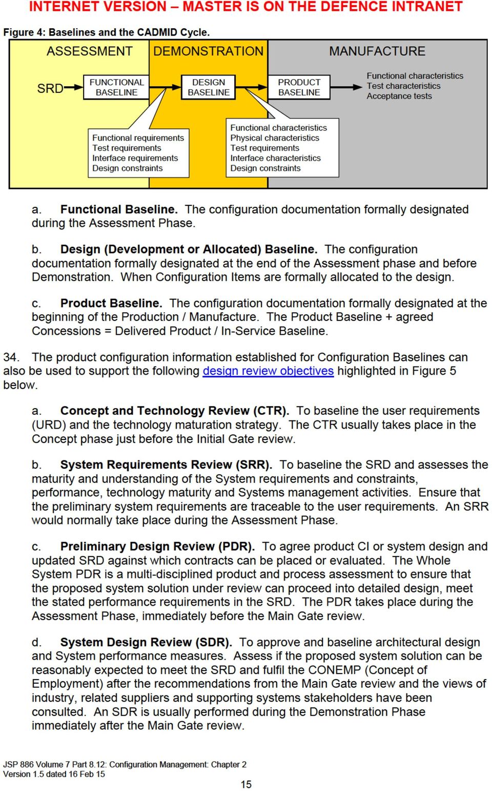
14 Figure 3: Configuration Information. CONFIGURATION BASELINES 29. Configuration Baselines should be established as a reference for further activities / future change. A Configuration Baseline consists of the approved configuration information to satisfy the requirements for design, verification, operation and support. (Reference ISO 10007) 30. Configuration Baselines provide stakeholders a mechanism for common understanding and an assurance that the product or system meets the contractual requirements. The level of detail for Configuration Baseline depends upon the degree of control required. 31. The recognition of a contractual deliverable Configuration Baseline provides the basis for In-Service configuration change by the Authority and contractual arrangements for Modification. 32. Before any product configuration documentation or data set is considered for baseline, it must be reviewed to ensure that the document is complete and valid for use. 33. Traditional CM practices can recognise the following product documentation baselines shown in Figure 4: JSP 886 Volume 7 Part 8.12: Configuration Management: Chapter 2 Version 1.5 dated 16 Feb 15 14


15
16 e. Critical Design Review (CDR). To baseline System design for production / manufacture. The CDR assesses the technical solution to ensure it has an expectation of meeting the URD and the SRD. A CDR normally occurs during the Demonstration phase prior to the transition to the Manufacture phase. f. Test / Trials Readiness Review (TRR). Agreement to commence System testing. At the TRR the whole system is assessed for readiness to undergo trial or test in the appropriate environment. A TRR can take place at any time but usually only once the whole system can be brought together. 35. Product configuration information established for the design reviews described above can also be used to evaluate the Support Maturity Levels (SML), see Figure 5 and the configuration management measures of effectiveness for each SML in to Chapter 3 Part The measures of effectiveness for each SML should be agreed with the supplier and included in the development or support contract. JSP 886 Volume 7 Part 8.12: Configuration Management: Chapter 2 Version 1.5 dated 16 Feb 15 16

17 Figure 5; Configuration Management Relationship and Baseline Support to Product Requirements, Acceptance and Design Review JSP 886 Volume 7 Part 8.12: Configuration Management: Chapter Version 1.5 dated 16 Feb

18 CONFIGURATION CHANGE MANAGEMENT Change Control - General 37. Configuration change management is applied through the process of establishing baseline reference points from which to control change. A Baseline reference point consists of a documented product definition baseline, which can include but not limited to; design information, software version documentation and associated validation and operational information. 38. A change to a Baseline can be initiated by the need to implement regulatory, safety, quality, or performance improvements including supportability arrangements or a need to meet new requirements for improved capability. 39. The purposes of configuration change management are to ensure: a. Control of Configuration Baselines. b. Consistency between product and product configuration information. c. Communication of change information. d. Change decisions understand the impact of change. e. Changes are necessary or offer significant benefit. f. Stakeholder interests are considered. g. Product interfaces are controlled. h. Concessions - are recorded and managed. i. Products are supportable after change. 40. Classified data, essential to the evaluation and disposition of change, should be submitted separately in accordance with the approved security procedures. CHANGE CONTROL - RESPONSIBILITIES THROUGH LIFE 41. A Supplier Design Organisation will be required, under the terms of the development contract, to ensure that configuration change management is applied to product / system development up to the delivery of the product baseline for In-Service use. 42. Once the product design drawings are completed under contract and sealed (design freeze) the supplier relinquishes Configuration Change Authority control, and therefore can no longer make changes unilaterally. At this point, the responsibility for configuration change decisions is transferred to the Authority s Delivery Team Leader responsible for In- Service design integrity. 43. The Delivery Team Leader is supported by a Configuration Control Board (CCB), subsidiary committee (s) and personnel with configuration management responsibilities. Note: Examples of Configuration Change Management responsibilities for the CCB, subsidiary committee (s) and configuration manager are contained in Chapter 3 Part 3. JSP 886 Volume 7 Part 8.12: Configuration Management: Chapter 2 18

19

20 g. Insertion of new technology. h. Correct defects (both preventive and corrective). i. Improve product support. 49. Prior to submission for valuation to the Configuration Change Authority all Change Proposals should be identified and documented. 50. ISO advises that Change Proposals should typically include the following information: a. Configuration item(s) and related information to be changed, including details of their title(s) and current revision status. b. A description of the proposed change. c. Details of other configuration items or information that may be affected by the change. d. The interested party preparing the proposal, and the date it was prepared. e. The reason for the change. f. The category of the change. 51. To support the evaluation of Change; additional details can include: a. Design, development and testing involved. b. Operational and maintenance documentation updates. c. Training requirements. d. Products affected, ie products in build and / or retrofit to existing product. e. Effects on spares and replacements. f. Interfaces with other equipment. 52. Further change management considerations during the In-Service phase are identified in Defence Standard 05-57, Annex D: Example Modification Proposal Form. The MOD Delivery Team and the Supplier may utilise or develop this Example Modification Proposal Form. Completion details are contained in Defence Standard In-Service configuration change across the MOD Domains is usually managed using the Modification and Alterations & Additions processes detailed within the Contractual Standards and processes identified in Figure 1. CHANGE CONTROL - EVALUATION 54. Evaluations of proposed changes must be documented and consider the risk / potential impact. The extent of an evaluation will depend upon the product complexity and change category, see paragraphs 61 to 66. JSP 886 Volume 7 Part 8.12: Configuration Management: Chapter 2 20
 and related information to be changed, including details of their title(s) and current revision status. b. A description of the proposed change. c. Details of other configuration items or information that may be affected by the change.")
21
22 c. Who will incorporate the change? (Reference ISO 10007). CHANGE CONTROL - IMPLEMENTATION AND VERIFICATION OF CHANGE 59. Considerations when implementing and verifying authorised change are: a. The release of product configuration information to relevant stakeholders. b. To ensure that action is taken by relevant stakeholders affected by the required change. c. Establish records of compliance with the authorised change. (Reference ISO 10007). Figure 8: Implementation and Verification of Change. Approved Change Proposal Plan verification and implementaiton Update product configuraiton information Update baseline (CSR) Update affected support elements Arrange retrofit to existing products Verify change Modified Product Updated configuration baseline 60. Stakeholders responsible for the change implementation must verify with the In- Service Configuration Control Authority or subsidiary committee that required change is implemented. This verification must be recorded to allow traceability. CHANGE CONTROL - CATEGORIES OF CHANGE 61. The categorisation of Alterations & Additions and Modifications for Surface Ships is detailed within BRd 8593 (17) Addition and Alteration (A&A) Procedures and Modifications in Surface Ships. 62. The Air Domain modification classifications are detailed within the Military Air Authority (MAA) Regulatory Article 5305 and MAP 01, Chapter 10 - Maintenance Airworthiness Process, Configuration Control. JSP 886 Volume 7 Part 8.12: Configuration Management: Chapter 2 22
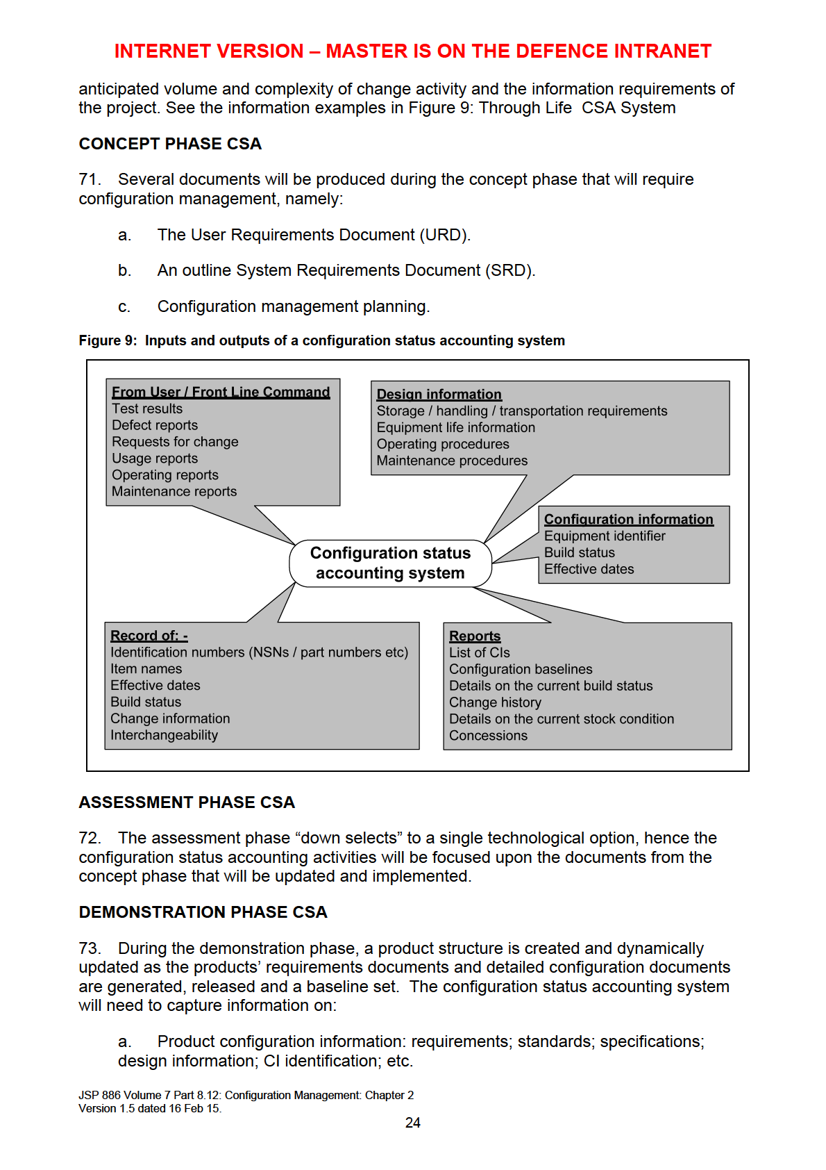
23 63. The Land Domain In-Service modification categories are detailed in JSP 886, Volume 5 Part 2A. 64. Supplier s proposing engineering changes, may wish to classify an Engineering Change Proposal (ECP) as either a Class I or Class II. An ECP shall be a Class I if the product Configuration Baselines, once established, are affected to the extent that the contract requirements are not met, or change to the Product Baseline, once established, impacts one or more of the following: a. Government Furnished Equipment (GFE). b. Safety (to include safety critical software). c. Security. d. Deliverable computer software. e. Compatibility or interoperability with interfacing items. f. Delivered operational and maintenance manuals. g. Interchangeability or replace-ability. or h. Skills, manning, training, biomedical factors or human engineering design. 65. Class I changes must be agreed by the Authority s representative and communicated to the Configuration Change Authority- CCB. 66. Class II ECP addresses all changes not classified as Class I. The Delivery Team Leader should have the ability to review Class II changes for concurrence of Class 1. (Reference ACMP 3) CHANGE CONTROL - CONCESSIONS 67. Concessions are contractual non-conformities and do not affect the product or system configuration baseline. A concession is generally limited to the delivery of the product that has nonconforming characteristics within specified limits for an agreed time or quantity of that product. (Reference ISO 10007). 68. Concessions form part of the Status Accounting records for a particular baseline, the management of Concessions should be contractually invoked in accordance with the Defence Standard 05-61, Part 1 Concessions. CONFIGURATION STATUS ACCOUNTING 69. Configuration Status Accounting (CSA) is the activity that results in records and reports that relate to product configuration information. (ISO 10007) Effective configuration management relies upon the availability of the up-to date product configuration information and the communication of change(s) to relevant stakeholders in a timely manner. Examples of through life CSA information is shown in Figure 9 below. 70. The depth and range of the information captured in the CSA should be based the nature of the product, the environment in which the product will be operated, the JSP 886 Volume 7 Part 8.12: Configuration Management: Chapter 2 23
24
25 b. Manufacturing. c. Testing and verification procedures. d. Change activity and history of the proposed and incorporated change requests. e. The effect of any change. f. Status and history of variants. 74. If the design of the product evolves, a record of the release of each product configuration information document, and subsequent revision to update the design baseline, is entered into the configuration accounting system. The accompanying data of this record s release will detail the applicability of the updates. 75. The following documented,configuration management information can require updating and implementation to reflect the evolving design of the product; a. SRD. b. Maintain URD. c. Configuration Management Plan. d. Requirements acceptance criteria. MANUFACTURE PHASE CSA 76. The information produced during the previous stages should be available for the manufacture phase. The information recorded in the database from the manufacture phase should include: a. The as built configuration of each product CI (by Serial number) including installation and removal of serialised and lot numbered components. b. The identities and product unit Serial numbers, which constitute the applicability of each approved major engineering change; the identifiers of the changes that have been released for any specific Serial numbered unit of a product. c. Superseded configuration records that reflect prior configurations of the product. DELIVERY TO THE AUTHORITY 77. The delivery of a product to the Authority should meet the requirements of the Contract Data Requirements. Other considerations during the delivery of a product may include: a. Delivery dates. b. Installation configuration. c. Warranty expiration dates for each unit delivered or installed. d. Service agreement type and expiration. JSP 886 Volume 7 Part 8.12: Configuration Management: Chapter 2 25
26 e. Training requirements. IN-SERVICE PHASE 78. Configuration status accounting during the in-service phase will vary greatly depending on the support implications / requirements; and any legal requirements placed on the type of product to support capability to fulfil operational requirements. The additional information shall be maintained on the configuration status accounting system during the in-service phase: a. As-maintained and as-notified baseline of the product. b. Product operation and maintenance information revision status. c. Information change requests and change notices. d. Restrictions or concessions on use of the product. e. Product performance degradation. f. Training requirements. DISPOSAL PHASE 79. Configuration status accounting during the disposal of a product in a cost effective and safe manner will depend on: a. If disposal of the product has adverse environmental implications. b. If the product requires a replacement. c. If the product is to be salvaged. Note: The disposal of some product will have legal and contractual implications that must be considered. JSP 886 Volume 7 Part 8.12: Configuration Management: Chapter 2 26
27 80. Typical status accounting throughout the CADMID cycle is shown in Table 2: Table 2: Typical Status Accounting Information throughout the CADMID Cycle. Life Cycle Phase C A D M I D Typical CSA Information And Activity Which Is Tailored To Suit Product And Project User Requirements Document (URD). System Requirements Document (SRD). Product structure / hierarchy information. Functional baseline. Design baseline. Product baseline. Configuration documentation. Configuration documentation change proposals. Configuration documentation change records. Change request proposal. Change request records. Product change request proposal. Product change request records. Concession and variance records. Verification / audit reports and actions. Usage records. Shelf life records. Product operation information / records. Product maintenance information / records. Restrictions (operational / facilities / etc). Product replacement information. Product interchangeability information. Product interface information. Product safety restrictions. Product environmental restrictions. Product salvage information. CONFIGURATION STATUS ACCOUNTING - RECORDS AND REPORTS 81. Configuration status accounting records are created during the configuration identification and change management activities. These records capture the process of configuration change and the product configuration information associated with contractual deliverable configuration Items; and continues for all subsequent In-Service baseline changes. 82. Throughout the product lifecycle the integrity and retrieval of configuration status records are to be protected from corruption / un-authorised change and retained in systems that permit retrieval and provide a means for disaster recovery. (ISO 10007). 83. Configuration status accounting reports provide the details and status of the configuration items (CIs) that are associated with the contractual deliverable product / system baseline. Records and reports are required for In-Service configuration management. JSP 886 Volume 7 Part 8.12: Configuration Management: Chapter 2 27
28 84. The Configuration status accounting records for the deliverable Product Baseline (PBL) should be certified for accuracy by the Supplier / Design Organisation responsible for each CI, prior to the approval for production and before acceptance of the Authority s Representative. 85. A complete product Configuration status accounting record should provide an overview of the constituent CIs by means of a family tree, to a level of detail agreed by the Delivery Team Leader and as defined in the contract conditions. 86. Commercial database package output should be compatible with the Authority s data import requirements. The format of the deliverable CSR should be compatible with the Authority s data import requirements, as specified in the contract. 87. The Configuration status accounting records and reference systems should: a. Provide a record for each CI by reference to part numbers, drawings lists and specifications of the planned, current and all earlier approved baselines including, where applicable, those of variants and those of ancillary items such as change / modification sets and kits, special tools, handling equipment, special to type test equipment and packaging. b. Identify any feature in the product with safety or operational implications that may require special tests or examinations. c. Provide a product breakdown structure showing the relationship of all the CIs making up the product by reference to drawings list numbers and/or an illustrated parts catalogue. d. Identify Non-Development / Commercial-off-the-shelf (COTS) & Government Furnished Assets (GFA) Items. e. Enable higher level CIs to be cross-referred to the subsidiary and associated CIs. f. List all items used in support of the product, such as special tools, design tools and models, special to type test equipment, handling equipment and packaging. g. Provide a baseline for each CI from which to define the subsequent as-fitted and future modification states of the product throughout its service life. h. Record the change status of the product by providing a reference to the change record of each CI, for all authorised modifications, amendments and system changes. CONFIGURATION AUDIT 88. Configuration Audit is a formal examination to verify that the requirements of the product configuration information are realised by the product / system Configuration Items (CIs). There are two types of audit: a. Functional Configuration Audit (FCA). b. Physical Configuration Audit (PCA). JSP 886 Volume 7 Part 8.12: Configuration Management: Chapter 2 28
29 89. Benefits of Configuration audit include: a. Validation for the integrity of the configuration documentation. b. Verification of consistency between a product and its configuration documentation. c. Determination that an adequate process is in place to provide continuing control of the configuration. DELIVERY TEAM INTERACTION WITH SUPPLIER CONFIGURATION AUDIT 90. The need for configuration audit is part of the contracted CM conditions; see MOD Policy in Chapter 1. The review of Supplier configuration audits reports of product or system CIs can help to obtain assurances for product verification. 91. The configuration audit schedule should be compatible with the availability information. eg engineering data, specifications, manuals, hardware / software product design information and reports. FUNCTIONAL CONFIGURATION AUDIT 92. A Functional Configuration audit (FCA) consists of the formal examination of test data and quality assurance records for a CI, prior to acceptance of the Product Baseline, to verify that the CI has achieved the performance and functional characteristics specified in the associated requirements configuration documentation. 93. An FCA should be conducted for each CI, or group of CIs, for which a separate development / requirement specification has been baselined. 94. By the end of the Assessment Phase and during the Demonstration Phase; Functional Configuration Audit (FCA) of CIs should be established, the results of which should be recorded and any action required taken. 95. During development a product usually goes through a series of builds, each version being progressively built towards the production model. Each model is tested against the conformance requirements as the functionality is progressively developed. During this development the following points may be considered: a. If a prototype or pre-production models are not to be produced, then the test data can be collected from the testing of the first production item. b. For complex System CIs, the FCA may be completed in increments. In such cases, a final FCA can be conducted to ensure that all the requirements have been satisfied. c. In cases where CI verification can only be completed after system integration and testing, the final FCA can be conducted along with the PCA. 96. The FCA can include a requirement to review the following test information: a. Compliance test procedures. b. Results from the compliance tests. JSP 886 Volume 7 Part 8.12: Configuration Management: Chapter 2 29
30 c. Test plans, specifications, descriptions, procedures and reports for the CI. d. A complete list of the successfully accomplished tests during which preacceptance data is recorded. e. A complete list of tests required by the test requirements but not yet performed, ie, to be performed as a system or subsystem test. f. Pre-production test results. g. An audit of formal test plans, specifications and procedures and compared against official test data. The results will be verified for completeness and accuracy. h. Interface requirements and the testing. i. All changes to product design and to test equipment to ensure that they have all been incorporated and completed. j. Design Reviews and Critical Design Review minutes; to ensure that all findings have been incorporated and completed. 97. An FCA audit report should be produced to detail the findings that should include: a. Test procedures and reports viewed and any deficiencies found. b. Completion dates for all discrepancies for agreement at the post audit meeting. PHYSICAL CONFIGURATION AUDIT 98. A Physical Configuration Audit (PCA) is the formal examination of the as-built configuration of a CI against its design documentation to ensure that the CI conforms to its specified physical requirements. 99. PCA should be established against the proposed production CI, (First Article Inspection) to assure that the requirements are met, prior to the Product Baseline. The PCA should not be started unless the FCA of the CI has already been successfully completed or is being carried out concurrently with the PCA During the PCA any differences between the physical configurations of the selected production CI and the development CIs used for the FCA should be evaluated to assure no degradation of the functional characteristics of the selected CI The Configuration Change Management control mechanism should be considered for audit to ensure that it correctly controls all internal and external changes The PCA should: a. Determine that the acceptance testing requirements prescribed by the documentation is adequate for the acceptance of CI production units by quality assurance activities; b. Include detailed audit of product design documentation, specifications, technical data, and tests utilised in the production of the CI, and consider operation and support documentation. JSP 886 Volume 7 Part 8.12: Configuration Management: Chapter 2 30
31 c. Include an audit of the released product configuration documentation and quality control records to make sure the hardware as built or software as coded configuration is reflected by this documentation. d. For Computer Software CIs (CSCIs) the product specification, Interface Design Document and Version Description Document should be considered by the PCA PCA considerations should assure that: a. Product design information and associated manufacturing processes are incorporated into the CI. b. Release records identify all relevant product design information. c. Outstanding changes to the product is recorded within relevant product design information CI configuration information and audit reference information can include: a. FCA report. b. CI specification / design information drawing Part Number. c. Identification - Part Number with possible Serial Number. d. Identification - approved nomenclature / nameplates. e. A list of CI approved and outstanding changes. f. List of concessions against the CI. g. Acceptance test procedures and associated test data. h. Operating and support publications, including all Maintenance manuals. i. Quality Assurance records for each CI. j. Complete shortage list. k. Recommended Spares List. l. Release documentation. m. Proposed Certification of Design. n. Draft Configuration Status Records. SOFTWARE CONFIGURATION AUDIT 105. The CM principles apply equally to hardware and software development and change management. The following software considerations should also be considered by CA: a. Compare detailed design descriptions with the software listing for accuracy and completeness. JSP 886 Volume 7 Part 8.12: Configuration Management: Chapter 2 31
32 b. Examine CSCI delivery media (disks, tapes, etc.) to ensure conformance with the software requirements specifications. c. Review the annotated listings for compliance with approved coding standards. d. Review all required operation and support documents for completeness, correctness, incorporation of comments made at critical Design Review, and adequacy to operate and support the CSCI(s). e. Ensure that configuration documentation details the relationship of the CSCI to the parts, components or assemblies and that executable data is properly described. For Firmware, ensure that the information completely describes the requirements for installation of the CSCI into the programmable parts or assemblies and that this information has been properly implemented. Where follow-on Acquisition of the firmware items is intended, ensure that the documentation has been accomplished to the level of detail necessary for the intended procurement. f. Using deliverable or Authority owned support software, assure by demonstration that each CSCI can be generated. The regenerated CSCI shall be compared to the actual CSCI delivery media to ensure that it is identical. FINAL CONFERENCE 106. The Authority s Authorised Representative should summarise the findings of the PCA from their perspective, and should identify all relevant remedial actions and corrective action (Discrepancies). A summary report should be available to all Authority s and Supplier team members All outstanding contractual requirements should be reviewed and any liability issues resolved The Supplier representative should summarise the Supplier s reactions and acceptance of the Authority actions on the Supplier in respect of: a. Certification of the CI. b. Outstanding contractual issues in respect to the CI. c. Outstanding liability issues (if any) Post PCA actions: a. The Supplier should be notified in writing by the Authority of acceptance or rejection of the PCA, the PCA status and comments, criticisms to be corrected, or rejection of the PCA and requirements for re-accomplishment. b. The Supplier should, after completion of the PCA, publish and distribute copies of the PCA as specified in the contract The Product configuration management design and operational information should be sealed for Production initiation. JSP 886 Volume 7 Part 8.12: Configuration Management: Chapter 2 32
33 CONFIGURATION AUDITS OF (NON-CONTRACTED) IN-SERVICE CHANGE 111. When not contracted with a Supplier / Design Organisation, the Delivery Team Leader is responsible for Configuration Audit of In-Service changes affecting the CI functional, physical and operational characteristics. In addition to the configuration audit guidance given above, see the Functional Configuration Audit Checklist in Table 3, and the Physical Configuration Audit Checklist at Table 4 below. Table 3: Functional Configuration Audit Checklist Functional Configuration Audit (FCA) Checklist CI Description Date: CI/CSCI Identifier: Release No. Requirements Yes No NA 1. Facilities for Conducting FCA Available. 2. Audit Team members have been identified and informed of audit. 3. Audit Team members are aware of their responsibilities. 4. General Requirements Specification (GRS) or all of the following two documents: Software Requirements Specification (SRS), System Specification (SS). 5. Waiver or Deviation List Prepared. 6. Verification Test Procedures Submitted (Test transactions). 7. Verification Test Procedures Reviewed and Approved (Test transactions). 8. Verification Testing Completed and results available (System Qualification Test). 9. Verification Test Data and Results Reviewed and Approved. 10. Test Results submitted (if available or applicable). 11. Verification Testing Witnessed. 12. Test Readiness Review I and II (TRR I and TRR II) completed. 13. Test Readiness Review I and II (TRR I and TRR II) minutes and open action items from past reviews available. 14. Copy of baseline and database change requests with their associated status accounting records along with all design (Problem Reports and Deficiency Reports (PRs and DRs), etc.) provided. 15. Other inputs as specified by the functional requirements and planning documents. Signature of FCA Team Members: Date: Results reviewed satisfy the requirements and are accepted (See attached comments). Results reviewed do not satisfy requirements (See attached comments and list of deficiencies). Approved by: Date: JSP 886 Volume 7 Part 8.12: Configuration Management: Chapter 2 33
34
35 CHAPTER 3: CONFIGURATION MANAGEMENT GUIDANCE PART 1: CONFIGURATION MANAGEMENT PLAN RECOMMENDED CONTENTS 1. This table of contents is a guide to a typical CM Plan, and must be tailored to suit the requirements of the project. The suggested contents of the sections, although detailed, are not exhaustive and some of the suggested inputs to the CMP may not be required and should be omitted. Omissions should be justified. 1. Introduction. This section should: Provide a programme overview Define the purpose and scope of the CMP and the extent of the CM to be applied to the activities associated with the project and product; Detail the security instructions that are specific to CM, which must reflect the requirements of the Security Management Plan. Contain information on any special features of the materiel, or the project programme, which have a bearing on CM. 2. Organisation and Responsibilities. This section should: Detail the programme organisation and list the points of contact in the project involved with CM, including; Front Line Command, the Delivery Team, the Supplier and Design Organisation. Identify the configuration management organisation and configuration change Authority for contracted product development and detail the organisational responsibilities Identify the relationships between the Delivery Team, the Supplier and Design Organisation, for the provision of CM during product development. Identify the In-Service - Configuration Control Authority and any subsidiary Configuration Management Committee(s); i.e. Configuration Control Board (CCB) and subsidiary Configuration Control Committee (CCC). Detail the roles and responsibilities of the CCB and any subsidiary CCC. Identify the In-Service relationships between the Delivery Team, the Supplier and Design Organisation, for the provision of CM. 3. Organisation CM Processes and Resources. List or detail the policies and directives for the CM of the product. Identify the change procedures throughout the development of the URD and SRD, the development of the deliverable product and or the In-service change and Disposal. List or detail the procedures used by the delivery team for the CM; eg. see Chapter 2, Figure 1. Identify the facilities such as, technical data models, databases and information systems with direct and indirect implication for the products CM. 4. Programme and Project Management. This section should: Detail the schedule and list the CM milestones of the programme project taken from the Through Life Management Plan Define the constraints on the CM of the product. Define the assumptions made when developing the CMP. JSP 886 Volume 7 Part 8.12: Configuration Management: Chapter 3 35
36 Define the product dependencies Identify the Contractual CM requirements in accordance with MOD CM policy and the specific requirements for the Domain systems. Detail the requirements for the transfer or availability of product configuration information from the Supplier to the Authority. Note: Projects may contract for the supplier to manage the CM information throughout the life of the project. In this case detail the requirements for the availability of product configuration information In- Service. 5 Configuration Identification and Documentation. This section should: Detail the Delivery Teams involvement in the Selection of Configuration Items (CI) Detail the Delivery Teams requirements for product / system CIs; see configuration items. Detail how Configuration Items (CI) will be identified; including Configuration Item of Supply for NATO Codification, (NATO Stock Number). 6. Configuration Change Control. This section shall define as a minimum the requirements for: Change Control Change Classifications Change Control Forms Problem Resolution Tracking System Change Requests System Change Requests Priorities Configuration Management Libraries Release Management Version Control For more details see Configuration Change Control 7. Interface Control and Management. This section should include: The arrangements for the use of non developmental items (NDI) and government furnished Information (GFI) and Government Furnished Equipment (GFE); Details of other projects and products which may be affected by changes to the product CIs and arrangements for the co-ordination and exchange of information; Methodologies to be adopted for the identification, control and documenting of equipment external interfaces; Relationships between databases for co-ordinating CM between products and different equipment at the platform or system level; Arrangements for co-ordination with other project requirements, e.g. Standardisation, codification and LSA (Logistic Support Analysis). 8. Configuration Status Accounting. This section should: Define how the project will ensure that the configuration activities are managed throughout the life cycle of the project and should reference the processes for collecting, recording, processing and maintaining all product configuration information. JSP 886 Volume 7 Part 8.12: Configuration Management: Chapter 3 36
37 Including details on: Formats and data elements for all configuration documentation; Specification, outline, installation and information drawings, where relevant. Design review records and certificates; Concessions; Computer software documentation; Proposed authorised change proposals; Correlation of change proposals on interfacing CIs; Formal review periodicity and the means for being viewed remotely by all authorised personnel; Archive and Retrieval of all product configuration information. For more information, see Configuration Status Accounting. 9. Baseline Management. This section shall define how and when baselines will be established and reviewed. see Configuration Baselines. 9. CM Repositories and Data Management. This section should: Describe the tools and methodologies for storing / handling the configuration management information and should cover: Description of all data media; How the management of data shall be controlled and verified throughout the product life cycle; Data ownership at working and organisational levels; Technical publication and user data; Data storage details, including access / limitation to data and prevention of data loss; 10. Support Software. Describe how any software will be configuration managed and how this is related to the hardware, with reference to Supplier Software Configuration Management Plan, where requested and available. 11. Configuration Auditing. This section should: Describe how Supplier Functional and Physical configuration audit reporting is to be managed, including: Review of Functional Configuration Audits (FCA) and the Physical Configuration Audits (PCA). Format for the reporting of the results of the FCA and PCA. Schedules for Supplier configuration audits, including the relevant design reviews up to Product / system acceptance. Schedules for Delivery Team In-Service configuration audits. For more information see Configuration Audits. 12. Configuration Documents Maintenance. Detail the instructions for the management of CM documents, including the CMP, with the means and methods of review, change control, change JSP 886 Volume 7 Part 8.12: Configuration Management: Chapter 3 37
38 authority, approved signatures, publication and issue. 13. Training. This section shall describe how training requirements will be identified, developed, carried out and ensure that training meets requirements. 14. Appendices. Glossary of Terms. Acronyms and Abbreviations. Reference Documents. Detail the reference specifications, standards, manuals and other publications applicable to the CM of the project and product. Each document shall be completely identified by title, document number, version number, issuing authority and date of issue. JSP 886 Volume 7 Part 8.12: Configuration Management: Chapter 3 38
39 PART 2: SELECTION CRITERIA - CONFIGURATION ITEMS 1. The selection criteria for CIs shall include, but is not limited to: a Safety. Where the failure of the CI causes a risk to personnel safety. Where the failure of the CI would affect the safety of the product b. Criticality. Where the sole failure of the CI causes product failure. Where the failure of the CI would critically affect the system, causing the system to become unavailable or unable to achieve mission objectives. Where the CI is important to the operation of the product. Where the CI is important for interfaces to one, or more, other systems. c. Complexity. Where the CI is complex or an integral part of the system. Where the CI has a long lead-time for manufacture. d. Costs and Purchasing Functionality and Performance. Items which have significant financial impact or are difficult to procure or manufacture relative to state-of-the-art techniques. Items which are used in large quantities (typically, at least 10 per cent of the configured items electronic parts count). e. Functionality and Performance. Where the failure of the CI would affect the system causing the system to become unavailable or unable to achieve mission objectives, or cause extensive/expensive maintenance and repair. Where the failure of the CI would prevent the Acquisition of data to evaluate system safety, availability, mission success, or need for maintenance/repair. Where the failure of the CI has stringent performance requirement(s) in its intended application relative to state-of-the-art techniques for the item. f. Integration, Interchangeability and Status as a Replaceable Item. Items that are used in more than one position in a product. Items that are used in more than one product or project. JSP 886 Volume 7 Part 8.12: Configuration Management: Chapter 3 39
40 Products, where items at different issues are interchangeable, but control is required. Products, where items at different issues are incompatible. g. Integrated Logistic Support (ILS). Items that have a known operating life, shelf life, or environmental exposure. This could be vibration, thermal, or a limitation which warrants controlled surveillance specified conditions. Items which are known to require special handling, transportation, storage and/or test precautions. Items that have a limited and predictable useful life and could be considered for replacement on a pre-planned basis for reliability, safety or economic reasons. 2. While identifying CIs the following topics must be taken into consideration: a. Define product structure and select sub-elements to be managed. b. Assign Unique Identifiers. Adopt a structured numbering system that can trace physical or functional dependencies through the hierarchy. Assign serial and lot numbers, as necessary, to differentiate individual units and groups of units, respectively. Control of all variants or issues of each product and possible fit of CIs. NATO Stock Numbering. c. Marking of Products. Wherever possible, products CIs should be marked or labelled with the manufacturer s reference / part number; variant number. Products CIs should be identified by NSN or in accordance with the unique identification requirements of the contract. d. Define Products Attributes. Functional parameters. Physical parameters. Interfaces with other items and products. Life of products. Conduct review and co-ordination of configuration documentation and if required obtain Front Line Command (customer) review and approval. JSP 886 Volume 7 Part 8.12: Configuration Management: Chapter 3 40
41 Establish release process; release configuration documentation; authorise use. Baseline configuration documentation for internal design control and, as applicable, for configuration change management. Ensure marking or labelling of products and documentation with applicable identifiers enabling correlation between the products, configuration documentation and associated data. Select configuration documentation types and formats. JSP 886 Volume 7 Part 8.12: Configuration Management: Chapter 3 41
42 PART 3: CONFIGURATION CHANGE MANAGEMENT RESPONSIBILITIES (EXAMPLE) OBJECTIVES 1. To ensure that all proposed change to systems, platforms and equipment are justified, developed, estimated, provisioned, assessed, validated, and reconciled to the allocated budget, before formal approval by the Authority s Configuration Change (Dispositioning) Authority. CONFIGURATION CHANGE AUTHORITY 2. The In-Service Configuration Change Authority is usually the platform Delivery Team Leader supported by the Configuration Control Board (CCB) 2. RESPONSIBILITIES 3. The Responsibilities of the Configuration Change Authority - CCB is generally to: a. Consider and make decisions on proposed changes to the equipment, specification or its design which affect project performance, cost, timescales or delivery. b. Approve and define the limits of delegated authority to any subsidiary committee(s). c. Resolve differences between the MOD, the Supplier and the Design Organisation if not the contractor, arising from the specification. d. Discuss issues of liability with Supplier and MOD Commercial Branch; refer concurrence of issues for settlement with MOD Commercial Director. e. Authorise the supplier to proceed with approved changes. f. Advise all Stakeholders of the decisions or recommendations of the Dispositioning Authority. g. Report on all matters on CM business, and produce minutes, circulating to all interested parties, including those affected by consequential actions, interchangeability, costs, spares or common parts. h. Ensure the preparation and maintenance of the Configuration Status Accounting Record for the CI or Master Record Index. i. Agree and record product or system Configuration Baseline 4. The responsibilities of a Subsidiary Change Management Committee is generally to; a. Provide a forum for dealing with technical and associated matters. b. Take decisions within delegated levels of authority The CCB can be supported by subsidiary change management committee (s) or personnel who have delegated authority to manage and approve changes within technical, cost and other risks constraints. 2. The levels of authority required to disposition and authorise change must recognise the impact of proposed change to the safety, complexity and integrity of the product or system. JSP 886 Volume 7 Part 8.12: Configuration Management: Chapter 3 42
43 c. Make recommendations to the Dispositioning Authority where delegations are exceeded. d. Assess Consequential actions, including affects on Common parts, Interchangeability and Interfaces (including interface with aircraft, Logistics, etc) and initiate activities where applicable. e. Acceptance of Design Records off contract. f. Conduct the gathering of cost elements for the Engineering Change when required by project. g. Recommend and manage the point of embodiment of authorised change, ensuing required; spares provision, "In-service", production support requirements including technical publications. h. Planning, tooling, test equipment or gauging requirements, trials etc. i. Evaluate materiel, stock, and advance ordering. j. Ensure availability of Engineering Change Advance Data Pack. k. Manage Salvage Actions. Note: An Equipment Manager may undertake the responsibilities of the subsidiary change management committee and report directly to the Configuration Change Authority - CCB. COMPOSITION 5. The CCB should comprise of a Chairman supported by persons having specialist knowledge of the business under discussion that may include representation from: a. Production Engineering. b. Manufacturing. c. Specialist adviser(s). d. Representative(s) of the Service users. e. Representative(s) of the Design Organisation. f. Representative(s) of the Suppliers affected. g. Representative(s) MOD Commercial. h. Front Line Command customer support. i. Quality Assurance. j. Configuration Management. k. Technical Secretary as required. 6. The Composition of subsidiary Change Management Committee is usually JSP 886 Volume 7 Part 8.12: Configuration Management: Chapter 3 43
44 a. Delivery Team Leader (Chairman). b. Delivery team Quality Representative. c. Representative(s) of the Design Organisation. d. Supplier production representatives. CONFIGURATION MANAGER 7. The role of a Configuration Manager / CM Focal Point is generally to: a. Ensure the maintenance of the Configuration Status Accounting Records or Master Record Index. b. Support to the Delivery Team Leader, with the assurances required by the Support Solution Envelope (SSE) 2.5, for Initial and Main Gate approvals. c. Ensure that MOD CM policy requirements are clearly translated into contractual requirements. d. Ensure that potential CM risks are included in the project Risk Register and managed accordingly. e. Progress and submit a Problem Report - Request for Change (RFC) to the CCB or subsidiary committee. f. Record RFC that fail to be approved for progression to an Engineering Change Proposal (ECP)./ Modification change proposal. g. Submit Engineering Change Proposal (s) to the Configuration Change Authority - CCB or subsidiary committee for Disposition. h. Monitor and record the progress of Configuration Change Authority - CCB authorised changes and progress Engineering Change Notices. i. Monitor the verification for the implementation of change modifications by stakeholders. Note: Approved ECP are developed into Engineering Change Notices that support the implementation of approved modifications. JSP 886 Volume 7 Part 8.12: Configuration Management: Chapter 3 44
45 PART 4: CONFIGURATION MANAGEMENT (SUPPORT MATURITY LEVELS) 1. The development of configuration management documentation can be assessed during the programme lifecycle using the 9 Support Maturity Levels (SML) detailed below, supporting the Integrated Logistic Support SML(s) defined in JSP 886 Volume 7, Part 2 Chapter To enable the Delivery Team to assess the maturity against success criteria, the measures of effectiveness for each SML detailed below; is to be agreed with the Supplier and included in the development or support contract. SUCCESS CRITERIA 3. See Configuration Management Policy Statement in Section 1. Support Maturity Level 1. URD Defined 2. Contractual SRD Defined 3. Preliminary Design Review Measure of Effectiveness a. CM strategy - planning supporting Initial Gate is established in accordance with JSP 886 Volume 7 Part 8.12 Chapter 2. b. CM is identified in the URD as a contract requirement. c. The principles of CM are used to support stakeholder engagement and requirements capture for the User Requirements Document (URD). d. The URD is Baselined during Concept and Technology Review (CTR) and Authorised for release. e. CM is considered and evaluated by the requirements of the Support Solution Envelope (SSE 2.5) for Initial Gate. f. High Level Supplier plans in response to ITT are evaluated for Supplier management intent to develop products under CM control in accordance with the Policy requirements in Chapter 1. a. CM planning to support Main Gate and Demonstration / Manufacture phases is established in accordance with Chapter 2. b. The Functional Baseline is established for initial System Requirements Document (SRD) c. Baseline CM documentation is identified in the contract data requirements list to support the System Requirements Review (SRR) and development of the SRD. d. The System of Systems Approach for CI integration at initial design is considered. e. CM is considered and evaluated by the requirements of the Support Solution Envelope (SSE 2.5) for Main Gate. a. Changes to the URD resulting from any SRD constraints are understood, managed and implemented. b. The SRD is Baselined for Preliminary Design Review (PDR). c. The System of Systems Approach for CI integration is considered for the preliminary design. d. Initial disposal considerations for Configuration Items (CIs). Risk If Not in Place The requirements for CM will not be identified or included in contracts. Ineffective development and Baseline for ITT and Contract requirements. No visibility or initial assurance assessment for Supplier CM. The CM requirements will not be identified or included as part of the contract conditions. The Supplier s Responsibilities for CM will not be understood / defined. The System / product design will not meet the expectations of the Front Line Commands as detailed in the URD. Loss of traceability between SRD and URD requirements. The product design status will be unknown and the design development will be undisciplined. System CIs integration issues can require product re-design with associated impacts to the programme. 4. Critical Design a. CM processes identified in CM planning are implemented by Demonstration phase. b. Configuration Items are identified and Allocated to the product / system architecture from the agreement during JSP 886 Volume 7 Part 8.12: Configuration Management: Chapter 3 45 The product design status will be unknown and design development will be undisciplined.
46 Review 5. Support Solution Validated 6. Logistic Support Date 7. In-Service Date 8. In-Service Support Reviews the System Design Review, (SDR). c. Product configuration information is configured and baselined for SDR. d. Product configuration information is managed throughout the product design - demonstration phase. e. Configuration Items (CIs) requiring special considerations such as life restrictions or disposal are considered for Unique Identification. a. CM processes identified in CM planning are implemented by Demonstration and initial Manufacture phases. b. The product / system design documentation is Baselined for Critical Design Review (CDR) and design freeze. c. Initial Functional Configuration Audit reports available from the Supplier. d. Operational elements of the product or system may be considered at this time for Initial Integrated Logistic Support (ILS) considerations. e. Disposal requirements are considered and identified within System / product configuration information. a. CM processes identified in CM planning are implemented within the Manufacture phase. b. Whole System / Product configuration information has a configuration baselined for Test / Trial Readiness Review (TRR). c. Integrated Test and Evaluation and Acceptance (ITEAP) requirements are established and available in accordance with planned arrangements d. Physical Configuration Audit reports are available from the Supplier for evaluation. e. Configured Operational information is available to support the Logistic Support date. f. CIs are identified under the NATO Codification requirements when designated as an Item of Supply for management by the MOD Joint Supply Chain. a. Platform, Systems and Product configuration information supports the Deliverable Baseline for In-Service use. b. Required product configuration information is delivered in accordance with the requirements of the Contract Data Requirement List (CDRL) or made available to the Authority s Representative to support In-Service use and management requirements. c. Configuration Management procedures are identified to manage In-service design integrity and configuration status accounting requirements. d. Logistic Information Repository (LIR) data being populated with data generated from system / product configuration information in accordance with In-Service requirements. e. Delivery Team CM planning for the In-Service phase reflects the MOD Regulatory and Domain requirements for In-Service configuration management and maintenance of design integrity. a. CM processes as required by MOD Regulatory Authorities and Domain requirements are implemented during the In-service phase. b. Contractual CM requirements and Supplier CM processes as detailed in CM planning are implemented during the In-service phase. c. Submarine and Surface Ship definition Databases are maintained and supported by configuration management process; to assure only authorised changes to the Platform, Without the formal identification and documentation of CIs, CM and known product structure is not plausible. The product design status will be unknown and the design development will be undisciplined. Without the formal identification and documentation of CIs, CM and known product structure is not plausible. The product design status will be unknown and the design development will be undisciplined. Without the formal identification and documentation of CIs, CM and known product structure is not plausible. The design status will be unknown and the acceptance of the system / product against the contract requirements may not be possible. Information to support systems safety cases will not be available. Design will be uncontrolled and operational compatibility unknown. Logistic Information Repository data will be incomplete. Design integrity may be compromised. The loss of Baseline configuration information can lead to the need for costly corrective action to establish the required information for continued use or further development. JSP 886 Volume 7 Part 8.12: Configuration Management: Chapter 3 46
47 9. Out of Service Date system and product baselines. d. Master Record Index documentation or similar configuration status records are maintained and supported by configuration management process to assure only authorised changes to the Platform, system and product baselines. a. Product definition information Configuration Status Accounting data and operational information is archived in accordance with Regulatory and Authority requirements, eg. Configuration datum packs, and Technical Publications. b. Configuration Items (CI)s requiring special disposal considerations are identifiable from the Product structure and traceable to enable effective management in accordance with the disposal plan. The loss of configuration information creates difficulties for the sale of MOD products. Possible environmental and safety impacts associated with product non traceability. JSP 886 Volume 7 Part 8.12: Configuration Management: Chapter 3 47
48 PART 5: CONFIGURATION MANAGEMENT ACTIVITIES FOR PROGRAM REVIEW AND ILS SUPPORT SUPPORT MATURITY LEVEL 1 USER REQUIREMENTS DEFINITION, CONCEPT PHASE AND CONCEPT TECHNOLOGY REVIEW Objectives 1. To baseline the User Requirements Document (URD) and establish the technology maturity strategy. 2. Determine the Contractual Configuration Management conditions for the Concept Phase, for Initial Gate approval and the Assessment Phase. 3. Provision of a CM assurance statement for the Support Solution Envelope (SSE 2.5) - Configuration Management (CM) Initial Gate. Supporting Activities 4. Consider any Concept study recommendations and the need for the System of Systems Approach to meet URD capability requirements. 5. Define and support the ILS strategy for the project, including. 6. The agreement of the Work Breakdown Structure. 7. The Development of the support strategy as part of the overall Procurement Strategy, against the programme baseline(s). CM Activities 8. Produce the Delivery Team Configuration Management (CM) Plan for the Concept and Assessment Phases with a Strategy for through life CM. Note: This planning can be referenced in support of the Initial Gate Assurance - SSE Baseline the URD - to include Regulatory requirements and constraints. 10. Define the CM requirements for the Concept study documentation and data files. 11. Ensure MOD internal "version control" of Concept study data files and documentation. 12. Define the CM contractual requirements for Invitation to Tender or Notice (ITT) / (ITN) in accordance with Policy requirements in Part 1 of this JSP and consider the need for a Deliverable CM plan from the contractor. 13. Consider the CM requirements for Pre-Contract Award Evaluation (PCAE) should this be required under the programme strategy. 14. Advise the levels of access (security requirements) to be considered in Supplier CM planning. JSP 886 Volume 7 Part 8.12: Configuration Management: Chapter 3 48
49 15. Where previously arranged for ITT / ITN undertake PCAE of the Supplier responses and planning for configuration management, recognising the scope and the life of the contract. 16. Evaluate Supplier high level CM planning in response to ITT / ITN to assure management intent from the Supplier, to develop products under configuration control. 17. Provide assurance recommendation for the Initial Gate Support Solution Envelope (SSE 2.5) following review of Supplier CM Planning in response to ITT / ITN and CM planning by the Delivery Team. Note: Where Supplier responses to ITT / ITN are not available it may be possible to evaluate any relevant, available Supplier CM planning from similar type contracts to gain a level of assurance for SSE 2.5.Support Maturity Level 2 - Contract Initial System Requirements Definition during the Assessment Phase and System Requirements Review. SUPPORT MATURITY LEVEL 2 - CONTRACT INITIAL SYSTEM REQUIREMENTS DEFINITION DURING THE ASSESSMENT PHASE AND SYSTEM REQUIREMENTS REVIEW Objective 18. To establish an agreed Initial System Requirements Baseline that recognises the maturity and understanding of the system requirements, constraints, performance, technology maturity and systems management activities. 19. Ensure that the Preliminary Design system requirements are traceable to the user requirements. Supporting Activities 20. Evaluate Product / System Functional Baseline as expressed in the Initial System Requirements Document (SRD) and check against the User Requirements Document (URD). CM Activities 21. Assure that the Supplier s product documentation and Initial SRD is configured and identified with links to the Functional Baseline. 22. Review and update Delivery Team CM planning & Information knowledge Management requirements for the Demonstration and Manufacture Phases and identify the MOD interaction with the Supplier for the acceptance of the product configuration Baseline for In-Service use. Develop a CM Strategy for the In-Service and Disposal phases. 23. Establish Delivery Team CM planning links to co-ordinated plans for Acquisition; ie: a. Requirements Acceptance Management Plan (RAMP). b. Through Life Management Plan (TLMP). c. Master Data Assumptions List. JSP 886 Volume 7 Part 8.12: Configuration Management: Chapter 3 49
50 d. User Requirements Document (URD). Note: CM Planning by the Delivery Team can be referenced in support of the Main Gate Assurances for SSE 2.5 Configuration Management. SUPPORT MATURITY LEVEL 3 - PRELIMINARY DESIGN REVIEW & SUPPORT TO MAIN GATE Objective 24. To agree product CIs and initial system design as detailed by updated SRD against which contracts are placed and evaluated to assure a whole system product and process assessment to ensure that the proposed system solution under review can proceed into detailed design and meet the stated performance requirements in the SRD. Supporting Activities 25. Review initial product / system design against the updated SRD Baseline. 26. Communicate with the Customer where the SRD requirements affect expectation as detailed by the URD and obtain from MOD Customer (Front Line Command), a view whether identified deficiencies against URD requirements are acceptable. 27. Consider Interoperability requirements and support to Standardisation. 28. Define and support the ILS strategy for the project, considering the co-ordination of all related disciplines and elements that may impact on development and delivery of fully supportable equipment, in conformance with DEFSTAN & MOD Policies. 29. Establish ILS requirements for contract and logistic support date and recognise in configuration documentation. Notes: 1. The Font Line Command has ownership of URD 2. The Deliver Team has ownership of the SRD, used as the basis for product and system acceptance. 3. The SRD provides a quality check on the fitness for purpose of the evolving URD by helping to address omissions and ambiguities in the URD. CM Activities & Contract Considerations 30. Ensure that the CM requirements established for ITT / ITN in accordance with the Policy requirements in Part 1 of this JSP are reflected in the contract requirements for product design / manufacture and acceptance by the MOD delivery Team. 31. Advise of the levels of access (security requirements) for Supplier CM planning. 32. Undertake a review of the Supplier planned arrangements for configuration management during the Demonstration and Manufacture Phases for product development, delivery and required In-Service information. JSP 886 Volume 7 Part 8.12: Configuration Management: Chapter 3 50
51 33. Identify the product configuration information required to support appropriate design reviews and to support the product acceptance from Supplier for In-Service use. Possible use if Contract Requirements Data List (CDRL). 34. Define or agree the format for the deliverable product configuration information and Configuration Status Record (CSR) or Master Record Index (MRI) is to be supplied. 35. Identify Non-Development Items e.g. COTS products and products provided as Government Furnished Assets / Equipment (GFA / GFE). Identify the configuration status of GFA / GFE products and Test facilities. 36. Items designated for NATO re-procurement for MOD supply chain; are to be identified by an NATO Supply Code for Manufacture (NSCM), the NATO Stock No. (NSN) or NATO Standard Stock No (NSSN) (Refer to DEFCON 117). 37. Arrange the transfer of Product Configuration Information where a MOD Organisation requires a Configuration Status Accounting (CSA) Baseline for In-Service use. 38. Where significant CM risk is identified, arrange Risk Based Surveillance with a Registered GQAR Organisation to review the management system associated with the perceived risk. SYSTEM DESIGN REVIEW (NON-SUPPORT MATURITY LEVEL) Objective 39. To approve and baseline architectural design and System performance measures, assess if the proposed system solution can be reasonably expected to meet the SRD and fulfil the Concept of Operations (CONEMP) after the recommendations from the Main Gate review and the views of industry, related suppliers and supporting systems stakeholders have been consulted. Supporting Activities 40. Refine and agree the SRD and Architecture models and assumptions based upon outputs from the contractor s system engineering process. 41. Communication with the Customer - (Front Line Command) where change(s) to requirements through SRD constraints affect expectation as detailed by the URD. 42. Record Trade-off decisions and record non-compliances / variance to the Requirements and Acceptance Documentation. 43. Development of Integrated Test and Evaluation Plan (ITEAP). 44. Consideration of Integrated Logistic Support (ILS) requirements in Design Reviews. CM Activities 45. Ensure that the linkage between the versions of the ITEAP and Validation and Verification Requirements Matrix is supported by Configuration Management (CM). 46. Assure the CM control and CM status for the outline ITEAP. JSP 886 Volume 7 Part 8.12: Configuration Management: Chapter Initial evaluation and identification of CIs that require tracking through life. 51
52 48. Review CI product documentation to assess the functional and physical characteristics. 49. Initial evaluation and identification of CIs that require special consideration for disposal. 50. Review initial Product Breakdown Structure of Configuration Items (CIs). SUPPORT MATURITY LEVEL 4 - CRITICAL DESIGN REVIEW Objective 51. To baseline System design for manufacture / production. Assesses the technical solution during the Critical Design Review (CDR) to ensure it has a reasonable expectation of meeting the URD and the SRD. Supporting Activities 52. System Design Baseline - Agree product / system Configuration Item(s) (CIs) within Product Baseline for manufacture. 53. Consider the CI functional and physical - interface characteristic to support System of Systems integration requirements. 54. Assure that compatibility is maintained between the product CIs and other interfacing system / platform CIs to support system integration (possibly software to hardware integration) and the System of Systems Approach. 55. Agree scope of product / system testing for product / system acceptance, (review of ITEAP). 56. Consideration of ILS requirements during Critical Design Review and in any subsequent Configuration Change Proposals (usually presented by the Contractor using Engineering Change Proposals). 57. Consider interoperability requirement and support to Standardisation. CM Activities 58. Assure version compatibility (as reported) between products / System CIs. 59. Evaluation and Identification of CIs that require tracking through life. 60. Evaluation and identification of CIs that require special consideration for disposal. 61. Review initial Functional Configuration Audit CI (test reports) from the Supplier; to gain assurance that the CI functional characteristics meet the URD and SRD requirements. 62. Review First Article Inspection reports to gain assurance that the CI physical characteristics meet the design requirements. 63. Review CI product breakdown structure to assure compatibility with URD and ILS requirements. JSP 886 Volume 7 Part 8.12: Configuration Management: Chapter 3 52
53 64. Review CI product documentation to assess and agree functional and physical characteristics. 65. Co-ordinate exchange of information, with other Delivery team(s) about system that can be affected by revised requirement. 66. Assure system Interface requirements - Review Interface Control Document against the CI product Breakdown structure. 67. Initiate Configuration Change Management Committee (CCMC) - A Configuration Change Management Committee (CCMC) is a formal gathering to discuss support matters post Logistic Support Date (LSD) and to authorise changes to the product, associated elements or the support. 68. Ensure correct Interaction between the Configuration Change Committee and the Configuration Control Board via integrated Terms of Reference. Integrated Logistic Support 69. The MOD Integration Logistic Support Manager (MILSM) will usually ensure that supportability aspects are represented at design reviews and during the product acceptance process. Manage Logistic Configuration 70. This activity includes the creation of a plan to manage the configuration and identification of the tools and management skills required for the creation and maintenance of the TLS configuration. It needs to address: a. Plan configuration management. b. Specify configuration. c. Configuration Change Management. d. Maintenance of the configuration status record. e. ILS Configuration audits. f. Verification and feedback. Acceptance of Support Recommendation 71. The ILS deliverables shall be reviewed to ensure that the ILS / SA tasks have been completed correctly; the logistic data is consistent with the design data and complete as well as being compatible with the proposed maintenance concept. The theoretical support recommendations shall be reviewed throughout the project in line with the increasing level of design definition. The final acceptance shall form part of the Factory Acceptance Process and shall be aimed at ensuring the support recommendations are appropriate and traceable to the actual design configuration being delivered. JSP 886 Volume 7 Part 8.12: Configuration Management: Chapter 3 53
54 SUPPORT MATURITY LEVEL 5 AND 6 SUPPORT SOLUTION VALIDATION, LOGISTIC SUPPORT DATE AND TEST READINESS REVIEW (TRR) Objective 72. Whole system is assessed for readiness to undergo trial or test in the appropriate environment. A TRR can take place at any time but usually only once the whole system can be brought together. Supporting Activities 73. Ensure that the linkage between the versions of the ITEAP and Validation and Verification Requirements Matrix. 74. Ensure required Interaction between the Contractor and Delivery Team e.g. via Local Technical Committee to support product / system acceptance. CM Activities 75. Assess Contractor s Class 1 Engineering Change Proposal(s) (ECP) that are designated to request change(s) affecting fit, form & function once the product baseline is agreed at CDR. Note: An ECP shall be a Class I if the product Configuration Baselines, once established, are affected to the extent that the contract requirements are not met, or change to the Product Baseline, once established, impacts one or more of the following: a. Government Furnished Equipment (GFE). b. Safety (to include safety critical software). c. Security. d. Deliverable computer software. e. Compatibility or interoperability with interfacing items. f. Delivered operational and maintenance manuals. g. Interchangeability or replace-ability. h. Skills, manning, training, biomedical factors or human engineering design. 76. A Class 1 ECP is to be evaluated, rejected or agreed by the Delivery Team Leader or his representative with this decision communicated to the Contractor s CCB. (Reference Def Stan Issue 6). SUPPORT MATURITY LEVEL 7 - IN-SERVICE DATE & DELIVERABLE PRODUCT ACCEPTANCE Objective 77. Product, system acceptance against SRD, ITEAP and contract requirements. JSP 886 Volume 7 Part 8.12: Configuration Management: Chapter 3 54
55 Supporting Activities 78. Ensure that requirements of the ITEAP and Validation and Verification Requirements Matrix (V&V RM) are satisfied by product CIs. CM Activities 79. Ensure that the Configuration Status Record (MRI / DIS) for the Product Baseline is certified for accuracy by the Supplier / Design Authority, prior to approval for production and before transfer off contract to In-service use. 80. Review Supplier Functional and Physical Audit Reports to support product acceptance. 81. Establish formal CM processes to manage the configuration of the project team s In- Service documentation. 82. Update CM planning to recognise In-Service configuration change management via Alterations and Additions and Modifications. 83. Configuration control of the datum pack as detailed in the Configuration Management Plan. Integrated Logistic Support and Acceptance 84. The ILS deliverables are usually reviewed by the MOD Integration Logistic Support Manager (MILSM) to ensure that the ILS / SA tasks have been completed correctly; the logistic data is consistent with the design data and complete as well as being compatible with the proposed maintenance concept. The theoretical support recommendations shall be reviewed throughout the project in line with the increasing level of design definition. The final acceptance shall form part of the Factory Acceptance Process and shall be aimed at ensuring the support recommendations are appropriate and traceable to the actual design configuration being delivered. SUPPORT MATURITY LEVEL 8 - IN-SERVICE SUPPORT REVIEW - RESPONSIBILITY FOR REVISED CAPABILITY AND DESIGN INTEGRITY (MODIFICATION OF CONFIGURATION BASELINES) Objectives 85. Ensure that compatibility is maintained between the product CIs and those in any interfacing product, system and platform. 86. After the design is accepted for In-service use - Subsequent changes to the delivered product (physical, functional & operational requirements) shall be changed in accordance with planned arrangements with design changes authorised by the Delivery team Leader. Supporting Activities 87. Maintain ownership of SRD and the Delivered product baseline that provides the basis for product / system configuration changes. 88. Established the MOD in the role of the Decider and the Supplier as the Provider once the product has been accepted from the Development contract for In-Service use. JSP 886 Volume 7 Part 8.12: Configuration Management: Chapter 3 55
56 89. Establish an In-Service Configuration Control Board (CCB) and where required a supporting subsidiary change management committee or personal who have delegated authority to manage and approve change within technical, cost and other risk constraints. 90. Utilise the Air Domain Modification Proposal Form in Def Stan 05-57, Annex D to manage In-Service configuration change(s). Otherwise utilise other Domain specific requirements detailed in Chapter 2, Table 1 of this JSP. 91. Ensure that supportability aspects are represented at Configuration Change Management Committee & Design Reviews. CM Activities 92. Update the Deliver Teams through life CM Planning to identify the In-Service change management process and identify the configuration management organisation, including the Configuration Control Board (CCB) and where required the subordinate Committee; responsible for assuring the integrity of the product design In-Service 93. Ensure the correct interaction between the CCB and any subsidiary committee(s) Exemplar Terms of Reference are provided in Section 2 Part 3 of this JSP. 94. The change management process should consider the configuration change management requirements in Chapter 2 of this JSP and ensure the: a. The initiation, identification and documentation of the need for change. b. The evaluation of the change by CCB or subsidiary committee or person. c. Recording and notification of the approval / rejection of configuration. d. Implementation planning to ensure that the required product configuration information and materiel is available for release to support the embodiment of an approved modification. e. Verification of change. f. Feedback to Delivery Team to assure implementation. 95. Maintain the Configuration Status Accounting (CSA) Baseline for In-Service use. 96. Implement a means for recording all changes to all CIs and maintaining traceability between all affected CIs. 97. Maintain Identification of CIs that require tracking through life. 98. Maintain Identification of CIs that require special consideration for disposal. 99. Consider Obsolescence issues of Non-Development Items e.g. COTS products during the evaluation of modification proposals Co-ordinate an exchange of information, with other project teams who have products that can be affected by changes to product / platform Configured Items Use formal CM processes to manage the configuration of the project team s internal documentation. JSP 886 Volume 7 Part 8.12: Configuration Management: Chapter 3 56
57 Configuration Status Accounting (CSA) 102. Ensure CSA is capable of recognising the potential for impact on interfacing CIs and track the progress of changes necessary to retain compatibility Maintain systems / tools to capture the information that defines product configuration. (Product Breakdown Structure & CI - Build of Materiel) Review the sentencing of Concessions under Def Stan Part 1 where Concessions are to be considered as part of the CSA records. Functional & Physical Configuration Auditing 105. Review Configuration audit reports for assurance of formal verification of product requirements and ensure recorded within the Configuration Status Accounting (CSA) In-Service Contract Considerations 106. Make recommendations for CM contract conditions in accordance with Part 1 of this JSP Make recommendations for the Domain Specific CM contract conditions, e.g. Defence Standards and MAA RA 5000 Series Ensure that Supplier CM planning interface with MOD Domain change management requirements and contract standards Identify within the Contract Requirements Data List (CDRL) the CM documentation required to support appropriate In-Service design reviews and to support the transfer of the product from Supplier to Under Ministry Control Define requirements for updated Configuration Status Record(s) and evaluate for acceptance upon delivery Where necessary; arrange Risk Based Surveillance with a registered GQAR Organisation to help mitigate identified significant CM risks with a Contractor Monitor Supplier progress of product development against revised baseline requirements Review the use of Non-Development Items e.g. COTS products and Government Furnished Equipment (GFE) and update as necessary. SUPPORT MATURITY LEVEL 9 - PRODUCT / SYSTEM DISPOSAL Objectives 114. Ability to transfer required product configuration Information with products designated for Sale after In-Service use (UK Trade and Investment - Defence and Security Organisation) 115. Ability to meet statutory and business requirements to retrieve product configuration Information and to trace product location. JSP 886 Volume 7 Part 8.12: Configuration Management: Chapter 3 57
58 CM Tasks 116. Transfer or Archive product configuration information and Configuration Status Accounting information, in accordance with statutory and business requirements. JSP 886 Volume 7 Part 8.12: Configuration Management: Chapter 3 58
59 PART 6: DEFINITIONS 1. Acquisition. The process of requirements setting, procurement management, support management and termination / disposal implying a whole life approach to defence capability (DEFSTAN 05-57). 2. Acquisition Life Cycle. The phases of a project that enable the delivery support and disposal of military capability (DEFSTAN 05-57). 3. Allocated Design Baseline: [Developmental]. The configuration documentation formally designated at the end of the Assessment phase and before the Demonstration phase. The Allocated - Design Baseline includes: a. The functional characteristics that are allocated from the Functional Baseline CIs. b. The test requirements demonstrating achievement of the functional characteristics. c. The interface characteristics with associated CIs. d. The Design constraints. (DEFSTAN 05-57) 4. Authority. Secretary of State for Defence or person (s) duly authorised to act on his behalf or as defined in the contract. (DEFSTAN 05-57) 5. Change Control Activities for control of the product after formal approval of its product configuration information. (ISO 10007:2003) 6. Computer Software Configuration Item (CSCI). Computer software designated for configuration management. (Allied Configuration Management Publication ACMP 6) 7. Computer Software Unit (CSU). An element, specified in the design of a Computer Software Component (CSC) that may be tested separately (ACMP 6) 8. Concession. Permission to use, embody; deliver or release a product that does not conform in full to contract requirements. A Concession can also apply prior to production / realisation (This process was formally known as a Production Permit / Deviation. (DEFSTAN Part 1) 9. Configuration. The functional and physical characteristics of materiel as described in its technical documentation and later achieved in the product. (DEFSTAN 05-57). 10. Configuration Audit. Checking an item for compliance with its configuration documentation (ACMP 6) 11. Configuration Baseline. The approved configuration documentation formally designated at a specific point in the CI life-cycle; that serves as reference for activities throughout the CI product life cycle. (Part ISO 10007). During Product development there are normally three baselines: a. Functional Baseline (FBL). b. Allocated Baseline (ABL): [Developmental]. JSP 886 Volume 7 Part 8.12: Configuration Management: Chapter 3 59
60 c. Product Baseline (PBL). 12. Configuration Control. The systematic evaluation, coordination, approval or disapproval and dissemination of all proposed changes to a CI and / or its configuration documentation; after formal establishment of its configuration baseline and verifying the implementation of all approved changes (ACMP 6) 13. Configuration Data. All data, regardless of form or characteristics, that is subject to configuration management. (ACMP 6). 14. Configuration Documentation. The current approved technical documentation for a CI. (ACMP 6). 15. Configuration Identification. The process of identifying and documenting the functional and physical characteristics of CI. (ACMP 6) 16. Configuration Item (CI). An item designated for configuration management (ACMP 6) 17. Configuration Management (CM) A discipline applying technical and administrative direction and surveillance to the following activities: a. Configuration Identification and Documentation. b. Configuration Control. c. Configuration status accounting and configuration data management. d. Configuration Audits. (ACMP 6) 18. Configuration Management Plan (CMP). The document that formally describes the scope of CM, the CM organization, the CM procedures for the programme as mutually agreed by all stakeholders and those responsible for CM 19. Configuration Status Accounting (CSA) The recording and reporting of the information that is needed to manage the configuration effectively, including a list of approved configuration documentation, the status of proposed changes to the configuration and the implementation status of approved changes. (ACMP 6) 20. Configuration Status Record. Record produced by the CSA process. It is the source database of configuration information to support the through life programme activities, including programme management, system engineering, manufacturing, software development, logistic support, maintenance and modification. The CSR should describe the status of the CI at any stage in its life cycle. (DEFSTAN 05-57) 21. Contract Data Requirements List (CDRL). A list of the data requirements that are authorized for a specific Acquisition; the CDRL forms part of the contract and direct the contractor to prepare and deliver data that satisfies specific approval and acceptance criteria. (ACMP 6) 22. Design Organisation. The organization entrusted to design the materiel to approved specifications. (ACMP 6) JSP 886 Volume 7 Part 8.12: Configuration Management: Chapter 3 60
61 23. Design Record. All information necessary to define the design, manufacture, packaging, testing, installation and servicing of a product. (DEFSTAN 05-57) 24. Design Review. A formal, documented engineering management process that is used to subject a design to a systematic critical study. Its purpose is to establish that the design satisfies the specified requirements. (DEFSTAN 05-57) 25. Developmental Configuration. The Supplier s technical documentation that defines the evolving configuration (design) during development; it is under the development Supplier s configuration control. (ACMP 6) 26. Dispositioning Authority. A person or group of persons, assigned responsibility and authority to make decisions on product configuration as defined in the requirements for product design, realisation, verification, operation and support. Note that a Dispositioning Authority; can also be known as a Configuration Control Board (CCB). Other Relevant interested parties within and outside the organization should be represented on the CCB. (ISO 10007) 27. Engineering Change. An alteration in the configuration of a CI and / or its configuration documentation after formal establishment of its configuration baseline. (ACMP 6). 28. Engineering Change Proposal. The formal documentation that is prepared to provide information in support an engineering change. (ACMP 6). 29. Engineering Data. All information associated with all engineering activities and recorded in documents such as drawings, associated lists, accompanying documents, manufacturer specifications, and standards, prepared by a design activity and relating to the design, manufacture, procurement, test, or inspection of items or services. (ACMP 6) 30. Functional Baseline (FBL. The configuration documentation formally designated during the Assessment Phase prescribing all necessary; functional characteristics; test requirements; CI interface characteristics associated with Key lower-level CI if any; and Design constraints. (ACMP 6) 31. Functional Characteristics. The initial design expressed in terms of quantitative performance parameters such as range, speed, lethality, reliability, maintainability, safety, and operating, logistics parameters. (ACMP 6) 32. Functional Configuration Audit. Formal examination of test data and quality assurance records for a CI, prior to acceptance of the Product Baseline (PBL), to verify that the CI has achieved the performance and functional characteristics specified in configuration documentation. (DEFSTAN 05-57) 33. Firmware. An ordered set of instructions and associated data stored in a way that is functionally independent of main storage, usually in a ROM. (ACMP 6) 34. Formal Engineering Change Proposal (ECP). The formal documentation that provides engineering information and other data in sufficient detail to support an engineering change proposal, its approval and its contractual authorization. (ACMP 6) 35. Interface Control. The delineation of the procedures and documentation, both administrative and technical, necessary for the identification and management of Functional and Physical Characteristics between two or more systems or CI. (ACMP 6) JSP 886 Volume 7 Part 8.12: Configuration Management: Chapter 3 61
62 36. Materiel. A generic term covering: complete systems, subsystems, assemblies, components, spare parts and material consumables, including computer software and firmware, and their related engineering data and documentation manuals. (ACMP 6) 37. NATO Stock Number. A 13 digit numeric data string, which on its own identified an Item of Supply in the NATO inventory. (DEFSTAN 05-57) 38. Non Developmental Item. A procured or procurable item available in the commercial market place requiring no modification to meet the requirements of the Authority. (DEFSTAN 05-57) 39. Part Number. A set of numbers, letters, symbols, or some combination thereof, assigned to uniquely identify the design of a specific part or item of materiel. (ACMP 6) 40. Physical Characteristics. Quantitative and qualitative expressions of material features; such as composition, dimensions, finishes, form, fit, and their respective tolerances. (DEFSTAN 05-57) 41. Physical Configuration Audit (PCA). Formal examination of the as built configuration of a CI to verify that it conforms to its product configuration documentation. (DEFSTAN 05-57) 42. Product Baseline (PBL). The configuration documentation for a CI formally designated at the beginning of Production prescribing: a. All necessary physical and functional characteristics of CIs; the selected functional characteristics designated for production acceptance testing. b. The production acceptance tests. (DEFSTAN 05-57) 43. Product Configuration Information. Requirements for product design, realization, verification, operation and support. (ISO 10007:2003) 44. Requirements Baseline. A documented common understanding of what the product is expected to do (its functional and performance requirements). It defines the capabilities the customer expects to receive from the product. (DEFSTAN 05-57) 45. Software Release. A configuration management action whereby a particular version of software is made available for a specific purpose (e.g. released for test). (ACMP 6) 46. System. Contains the total package of parts, through sub-systems and includes related facilities, items, material, services, and personnel required for its operation to the degree that it can be considered a self-sufficient item in its intended operational or nonoperational and/or support environment. (ACMP 6) 47. Technical Data. Recorded information of a technical nature, regardless of form or characteristics; Technical Data may document research, developmental, or engineering work or be used to define a design or process or to procure, support, maintain, or operate materiel. The data may be graphic or pictorial delineation in media such as drawings or photographs, text in specifications or related performance or design type documents, or computer printouts. Technical Data does not include computer software. (DEFSTAN 05-57) JSP 886 Volume 7 Part 8.12: Configuration Management: Chapter 3 62
63 48. Technical Review. A management review conducted at logical transition points, used to determine the contractor's progress and compliance to technical and contractual requirements. (ACMP 6) 49. Verification. Confirmation, by objective evidence, that the product meets the physical and functional requirements for which it was designed and conforms to specified requirements. 50. Version Description Document (VDD). A Version Description Document (VDD) identifies and describes a version of a Computer Software Configuration Item (CSCI) and identifies, by reference to the applicable Engineering Change Proposal and Notices all changes to the CSCI since the last VDD was issued. (ACMP 6) JSP 886 Volume 7 Part 8.12: Configuration Management: Chapter 3 63
JSP 886 THE DEFENCE LOGISTIC SUPPORT CHAIN MANUAL VOLUME 7 INTEGRATED LOGISTICS SUPPORT PART 8.11 QUALITY MANAGEMENT
 JSP 886 THE DEFENCE LOGISTIC SUPPORT CHAIN MANUAL VOLUME 7 INTEGRATED LOGISTICS SUPPORT PART 8.11 QUALITY MANAGEMENT THE MASTER VERSION OF JSP 886 IS PUBLISHED ON THE DEFENCE INTRANET. FOR TECHNICAL REASONS,
SOFTWARE CONFIGURATION MANAGEMENT GUIDEBOOK
 Office of Safety and Mission Assurance NASA-GB-9503 SOFTWARE CONFIGURATION MANAGEMENT GUIDEBOOK AUGUST 1995 National Aeronautics and Space Administration Washington, D.C. 20546 PREFACE The growth in cost
JSP 886 THE DEFENCE LOGISTIC SUPPORT CHAIN MANUAL VOLUME 2 INVENTORY MANAGEMENT PART 9 THE MANAGEMENT OF ASSETS
 JSP 886 THE DEFENCE LOGISTIC SUPPORT CHAIN MANUAL VOLUME 2 INVENTORY MANAGEMENT PART 9 THE MANAGEMENT OF ASSETS THE MASTER VERSION OF JSP 886 IS PUBLISHED ON THE DEFENCE INTRANET. FOR TECHNICAL REASONS,
How To Support Software Support
 JSP 886 DEFENCE LOGISTICS SUPPORT CHAIN MANUAL VOLUME 7 INTEGRATED LOGISTICS SUPPORT PART 4 SOFTWARE SUPPORT THE MASTER VERSION OF JSP 886 IS PUBLISHED ON THE DEFENCE INTRANET. FOR TECHNICAL REASONS, EXTERNAL
JSP 886 DEFENCE LOGISTICS SUPPORT CHAIN MANUAL VOLUME 7 SUPPORT ENGINEERING PART 8.05 TECHNICAL DOCUMENTATION
 JSP 886 DEFENCE LOGISTICS SUPPORT CHAIN MANUAL VOLUME 7 SUPPORT ENGINEERING PART 8.05 TECHNICAL DOCUMENTATION THE MASTER VERSION OF JSP 886 IS PUBLISHED ON THE DEFENCE INTRANET. FOR TECHNICAL REASONS,
JSP 886 THE DEFENCE LOGISTICS SUPPORT CHAIN MANUAL VOLUME 3 SUPPLY CHAIN MANAGEMENT PART 11 LOGISTIC INFORMATION SYSTEMS DATA MANAGEMENT
 JSP 886 THE DEFENCE LOGISTICS SUPPORT CHAIN MANUAL VOLUME 3 SUPPLY CHAIN MANAGEMENT PART 11 LOGISTIC INFORMATION SYSTEMS DATA MANAGEMENT THE MASTER VERSION OF JSP 886 IS PUBLISHED ON THE DEFENCE INTRANET.
Configuration Management ISO 10007
 Configuration Management ISO 10007 Introduction Configuration Management Overview: What is Configuration Management? Collection of tools, techniques and experience designed to reduce costs and improve
NATO STANDARD AQAP-2310 NATO QUALITY MANAGEMENT SYSTEM REQUIREMENTS FOR AVIATION, SPACE AND DEFENCE SUPPLIERS
 NATO STANDARD AQAP-2310 NATO QUALITY MANAGEMENT SYSTEM REQUIREMENTS FOR AVIATION, SPACE AND DEFENCE SUPPLIERS Edition A Version 1 April 2013 NORTH ATLANTIC TREATY ORGANIZATION ALLIED ADMINISTRATIVE PUBLICATION
NATO GUIDANCE ON THE USE OF THE AQAP 2000 SERIES
 NATO GUIDANCE ON THE USE OF THE AQAP 2000 SERIES (June 2003) I ORIGINAL Page blank II ORIGINAL NORTH ATLANTIC TREATY ORGANIZATION NATO STANDARDISATION AGENCY (NSA) NATO LETTER OF PROMULGATION June 2003
Certified Professional in Configuration Management Glossary of Terms
 Certified Professional in Configuration Management Glossary of terms used in Configuration Management Issue 2007.07 Association of the International Certified Configuration Manager e.v. Copyright 2007,
Space Project Management
 EUROPEAN COOPERATION FOR SPACE STANDARDIZATION Space Project Management Configuration Management Secretariat ESA ESTEC Requirements & Standards Division Noordwijk, The Netherlands Published by: Price:
074-8432-552 Page 1 of 7 Effective Date: 12/18/03 Software Supplier Process Requirements
 Page 1 of 7 Software Supplier Process Requirements 1.0 QUALITY SYSTEM FRAMEWORK 1.1 QUALITY POLICY The Seller shall document and implement a quality program in the form of Quality manual or detailed Quality
Superseded by T MU AM 04001 PL v2.0
 Plan T MU AM 04001 PL TfNSW Configuration Management Plan Important Warning This document is one of a set of standards developed solely and specifically for use on the rail network owned or managed by
Office for Nuclear Regulation
 ONR GUIDE LC17 Management Systems Document Type: ONR Nuclear Safety Technical Inspection Guide Unique Document ID and Revision No: NS-INSP-GD-017 Revision 2 Date Issued: November 2012 Review Date: November
In-Service Design Changes
 UNCONTROLLED COPY WHEN PRINTED Regulatory Article 5312 RA 5312 In-Service Design Changes Rationale Following the introduction of an aircraft type into Service use it may be necessary to incorporate design
JSP 886 DEFENCE LOGISTICS SUPPORT CHAIN MANUAL VOLUME 7 SUPPORTABILITY ENGINEERING PART 2 INTEGRATED LOGISTIC SUPPORT MANAGEMENT
 JSP 886 DEFENCE LOGISTICS SUPPORT CHAIN MANUAL VOLUME 7 SUPPORTABILITY ENGINEERING PART 2 INTEGRATED LOGISTIC SUPPORT MANAGEMENT THE MASTER VERSION OF JSP 886 IS PUBLISHED ON THE DEFENCE INTRANET. FOR
NATO QUALITY ASSURANCE REQUIREMENTS FOR DESIGN, DEVELOPMENT AND PRODUCTION
 NATO QUALITY ASSURANCE REQUIREMENTS FOR DESIGN, DEVELOPMENT AND PRODUCTION AQAP 2110 (June 2003) I ORIGINAL Page blank II ORIGINAL NORTH ATLANTIC TREATY ORGANIZATION NATO STANDARDISATION AGENCY (NSA) NATO
CORPORATE QUALITY MANUAL
 Corporate Quality Manual Preface The following Corporate Quality Manual is written within the framework of ISO 9001:2008 Quality System by the employees of CyberOptics. CyberOptics recognizes the importance
Life Cycle Support Information System. Training Guide
 Life Cycle Support Information System Training Guide This manual is intended for both the end user and the administrator of the LCSIS tool suite. You are free to copy and distribute this manual without
AEROSPACE STANDARD. Quality Management Systems - Requirements for Aviation, Space and Defense Organizations RATIONALE
 AEROSPACE STANDARD AS9100C Issued 1999-11 Revised 2009-01 Superseding AS9100B Quality Management Systems - Requirements for Aviation, Space and Defense Organizations RATIONALE This standard has been revised
Company Quality Manual Document No. QM Rev 0. 0 John Rickey Initial Release. Controlled Copy Stamp. authorized signature
 Far West Technology, Inc. ISO 9001 Quality Manual Document No.: QM Revision: 0 Issue Date: 27 August 1997 Approval Signatures President/CEO Executive Vice President Vice President/CFO Change Record Rev
CHAPTER 7 Software Configuration Management
 CHAPTER 7 Software Configuration Management ACRONYMS CCB CM FCA MTBF PCA SCCB SCI SCM SCMP SCR SCSA SEI/CMMI SQA SRS USNRC INTRODUCTION Configuration Control Board Configuration Management Functional Configuration
Table of Contents 1. SCOPE... 3 2. APPLICABLE DOCUMENTS... 4 3. TERMS AND DEFINITIONS... 4 4. QUALITY MANAGEMENT SYSTEM...4-8
 Table of Contents 1. SCOPE... 3 2. APPLICABLE DOCUMENTS... 4 3. TERMS AND DEFINITIONS... 4 4. QUALITY MANAGEMENT SYSTEM...4-8 5. MANAGEMENT RESPONSIBILITY...8-9 6. RESOURCE MANAGEMENT... 10 7. PRODUCT
SOFTWARE VERIFICATION RESEARCH CENTRE SCHOOL OF INFORMATION TECHNOLOGY THE UNIVERSITY OF QUEENSLAND. Queensland 4072 Australia TECHNICAL REPORT
 SOFTWARE VERIFICATION RESEARCH CENTRE SCHOOL OF INFORMATION TECHNOLOGY THE UNIVERSITY OF QUEENSLAND Queensland 4072 Australia TECHNICAL REPORT No. 99-30 A Survey of International Safety Standards Axel
Engineering Procedure
 Engineering Procedure Design EPD 0020 INVENTORY MANAGEMENT ENGINEERING RESPONSIBILITIES Owner: Approved by: Manager, Engineering Standards and Configurations Jagath Peiris Manager Engineering Standards
DEPARTMENT OF DEFENSE INTERIM STANDARD PRACTICE CONFIGURATION MANAGEMENT
 NOT MEASUREMENT SENSITIVE MIL-STD-3046(ARMY) 06 March 2013 DEPARTMENT OF DEFENSE INTERIM STANDARD PRACTICE CONFIGURATION MANAGEMENT AMSC 9275 AREA SESS DISTRIBUTION STATEMENT A. Approved for public release;
CONFIGURATION MANAGEMENT PLAN GUIDELINES
 I-680 SMART CARPOOL LANE PROJECT SYSTEM ENGINEERING MANAGEMENT PLAN CONFIGURATION MANAGEMENT PLAN GUIDELINE SECTIONS: PLAN GUIDELINES 1. GENERAL 2. ROLES AND RESPONSIBILITIES 3. CONFIGURATION MANAGEMENT
Quality management systems
 L E C T U R E 9 Quality management systems LECTURE 9 - OVERVIEW Quality management system based on ISO 9000 WHAT IS QMS (QUALITY MANAGEMENT SYSTEM) Goal: Meet customer needs Quality management system includes
Rail Network Configuration Management
 Division / Business Unit: Function: Document Type: Enterprise Services Engineering Procedure Rail Network Configuration Management Applicability ARTC Network Wide SMS Publication Requirement Internal /
JSP 886 DEFENCE LOGISTIC SUPPORT CHAIN MANUAL VOLUME 2 INVENTORY MANAGEMENT PART 8 LEARNING AND DEVELOPMENT TO SUPPORT INVENTORY MANAGEMENT
 JSP 886 DEFENCE LOGISTIC SUPPORT CHAIN MANUAL VOLUME 2 INVENTORY MANAGEMENT PART 8 LEARNING AND DEVELOPMENT TO SUPPORT INVENTORY MANAGEMENT THE MASTER VERSION OF JSP 886 IS PUBLISHED ON THE DEFENCE INTRANET.
5 FAH-5 H-520 LIFE CYCLE MANAGEMENT
 5 FAH-5 H-520 LIFE CYCLE MANAGEMENT (CT:ITS-5; 02-05-2013) (Office of Origin: (IRM/BMP/SPO/PM) 5 FAH-5 H-521 CONFIGURATION MANAGEMENT REQUIREMENTS Configuration management (CM) is a function deployed throughout
Department of Administration Portfolio Management System 1.3 June 30, 2010
 E 06/ 30/ 2010 EX AM PL 1. 3 06/ 28/ 2010 06/ 24/ 2010 06/ 23/ 2010 06/ 15/ 2010 06/ 18/ 2010 Portfolio System 1.3 June 30, 2010 Contents Section 1. Project Overview... 1 1.1 Project Description... 1 1.2
ITIL A guide to service asset and configuration management
 ITIL A guide to service asset and configuration management The goal of service asset and configuration management The goals of configuration management are to: Support many of the ITIL processes by providing
Space project management
 ECSS-M-ST-40C Rev. 1 Space project management Configuration and information management ECSS Secretariat ESA-ESTEC Requirements & Standards Division Noordwijk, The Netherlands Foreword This Standard is
<name of project> Software Project Management Plan
 The document in this file is adapted from the IEEE standards for Software Project Management Plans, 1058-1998, which conforms to the requirements of ISO standard 12207 Software Life Cycle Processes. Tailor
Lockheed Martin Tactical Aircraft Systems (LMTAS) Fort Worth, Texas CONFIGURATION MANAGEMENT REQUIREMENTS FOR SUPPLIERS AND SUBCONTRACTORS.
 Fort Worth, Texas CONFIGURATION MANAGEMENT REQUIREMENTS FOR SUPPLIERS AND SUBCONTRACTORS.") Lockheed Martin Tactical Aircraft Systems (LMTAS) Fort Worth, Texas CONFIGURATION MANAGEMENT REQUIREMENTS FOR SUPPLIERS AND SUBCONTRACTORS Approved: //signed// J. K. Goodman, Manager Configuration Management
Lockheed Martin Tactical Aircraft Systems (LMTAS) Fort Worth, Texas CONFIGURATION MANAGEMENT REQUIREMENTS FOR SUPPLIERS AND SUBCONTRACTORS Approved: //signed// J. K. Goodman, Manager Configuration Management
The Configuration Management process area involves the following:
 CONFIGURATION MANAGEMENT A Support Process Area at Maturity Level 2 Purpose The purpose of is to establish and maintain the integrity of work products using configuration identification, configuration
National Information Assurance Certification and Accreditation Process (NIACAP)
") NSTISSI No. 1000 April 2000 National Information Assurance Certification and Accreditation Process (NIACAP) THIS DOCUMENT PROVIDES MINIMUM STANDARDS. FURTHER INFORMATION MAY BE REQUIRED BY YOUR DEPARTMENT
NSTISSI No. 1000 April 2000 National Information Assurance Certification and Accreditation Process (NIACAP) THIS DOCUMENT PROVIDES MINIMUM STANDARDS. FURTHER INFORMATION MAY BE REQUIRED BY YOUR DEPARTMENT
Configuration Management Practices
 Safety Critical Software Management Practices Linda Westfall Westfall Team, Inc. International Conference on Software Quality ICSQ 2011 Copyright 1999-2010 Westfall Team, Inc. All Rights Reserved. Management
The use of computer systems
 Technology Update Computer Systems Validation, Part 1 Software Purchase and GCP Compliance Teri Stokes Teri Stokes, PhD, is senior consultant and director of GXP International, 131 Sudbury Road, Concord,
UNCONTROLLED COPY WHEN PRINTED
 UNCONTROLLED COPY WHEN PRINTED Regulatory Article 4947 This RA has been substantially re-written; for clarity no change marks are presented - please read RA in entirety RA 4947 - Continuing Airworthiness
IRCA Briefing note ISO/IEC 20000-1: 2011
 IRCA Briefing note ISO/IEC 20000-1: 2011 How to apply for and maintain Training Organization Approval and Training Course Certification IRCA 3000 Contents Introduction 3 Summary of the changes within ISO/IEC
MANAGEMENT SYSTEM FOR A NUCLEAR FACILITY
 GUIDE YVL A.3 / 2 June 2014 MANAGEMENT SYSTEM FOR A NUCLEAR FACILITY 1 Introduction 5 2 Scope of application 6 3 Management system 6 3.1 Planning, implementation, maintenance, and improvement of the management
Configuration Management Self Assessment Checklist
 Configuration Management Self Assessment Checklist Introduction: The purpose of this Configuration Management (CM) Self- Assessment Checklist is to ensure that the Organization correctly understands the
DEFENCE INSTRUCTIONS (GENERAL)
") DEFENCE INSTRUCTIONS (GENERAL) New instruction 0 LOG 4 5 012 Regulation of technical integrity of Australian Defence Force materiel Department of Defence CANBERRA ACT 2600 10 September 2010 Issued with
DEFENCE INSTRUCTIONS (GENERAL) New instruction 0 LOG 4 5 012 Regulation of technical integrity of Australian Defence Force materiel Department of Defence CANBERRA ACT 2600 10 September 2010 Issued with
Surgi Manufacturing Quality Manual
 Surgi Manufacturing Page 1 of 18 Approvals: QA: Eng. Mgt. : A Date: 18Aug98 1. Introduction... 4 1.1 Scope... 4 1.2 Purpose... 4 1.3 Authority... 4 1.4 Issue of the Manual... 4 1.5 Amendments... 4 1.6
Wharton Construction Ltd. Quality Manual. Kellaw Road Yarm Road Business Park Darlington DL1 4YA
 Quality Manual Kellaw Road Yarm Road Business Park Darlington DL1 4YA MANUAL IDENTIFICATION This document is a controlled/uncontrolled copy. Copy Number:...of... Issued to... Title... Holders of controlled
Quality Management System General
 Audit Date: Quality Management System General Requirement: 4.1 and 4.2.2-QMS General Verify Scope Comments/Evidence/Findings: Verify the Exclusions is applicable and justified How are the processes in
JSP 886 DEFENCE LOGISTIC SUPPORT CHAIN MANUAL VOLUME 4 MATERIEL ACCOUNTING PART 4 GOVERNMENT FURNISHED EQUIPMENT
 JSP 886 DEFENCE LOGISTIC SUPPORT CHAIN MANUAL VOLUME 4 MATERIEL ACCOUNTING PART 4 GOVERNMENT FURNISHED EQUIPMENT THE MASTER VERSION OF JSP 886 IS PUBLISHED ON THE DEFENCE INTRANET. FOR TECHNICAL REASONS,
SUPPLIER QUALITY MANAGEMENT SYSTEM QUESTIONNAIRE
 Company Name Street Address City, State, Zip code Phone Number Fax Company Website Email Address ORGANIZATION NAME PHONE NUMBER EMAIL ADDRESS President/CEO General Manager Engineering Manager Production
TÜV UK Ltd Guidance & Self Evaluation Checklist
 ISO 9001:2015 Revision TÜV UK Ltd Guidance & Self Evaluation Checklist Why ISO 9001 is changing All ISO management system standards are subject to a periodic review under the rules by which they are written.
Quality Management System Manual
 Quality Management System Manual Assurance ISO / AS Manual Quality Management System EXCEEDING ALL EXPECTATIONS Since our inception in 1965, Swiss-Tech has supplied the medical, aerospace, hydraulic, electronic
Quality Manual. This manual is proprietary and no part thereof shall be copied without written authorisation from the company. Ref: Quality Manual.
 This manual is proprietary and no part thereof shall be copied without written authorisation from the company Ref: Quality Manual.ind Issue: June 2009 INDEX 1 Amendment Status 2 Controlled Distribution
Key Aspects of Configuration Management. NOvA Working Group Meeting 1
 Key Aspects of Configuration Management NOvA Working Group Meeting 1 Excerpts from ANSI/EIA-649 on Configuration Management The purpose and benefits of configuration management include the following: Product
Vigilant Security Services UK Ltd Quality Manual
 Quality Manual Date: 11 th March, 2014 Issue: 5 Review Date: 10 th March 2015 VSS-COM-PRO-001 SCOPE This Quality Manual specifies the requirements for the Quality Management System of Vigilant Security
Software Quality Subcontractor Survey Questionnaire INSTRUCTIONS FOR PURCHASE ORDER ATTACHMENT Q-201
 PURCHASE ORDER ATTACHMENT Q-201A Software Quality Subcontractor Survey Questionnaire INSTRUCTIONS FOR PURCHASE ORDER ATTACHMENT Q-201 1. A qualified employee shall be selected by the Software Quality Manager
Uncontrolled Document
 SOUTHWEST RESEARCH INSTITUTE QUALITY SYSTEM MANUAL July 2015 Revision 5 Quality System Manual Page iii TABLE OF CONTENTS 1.0 PURPOSE... 1 2.0 SCOPE... 1 3.0 TERMS AND DEFINITIONS... 2 4.0 QUALITY MANAGEMENT
ISO 9001:2000 AUDIT CHECKLIST
 ISO 9001:2000 AUDIT CHECKLIST No. Question Proc. Ref. Comments 4 Quality Management System 4.1 General Requirements 1 Has the organization established, documented, implemented and maintained a quality
ISO 9001: 2008 Boosting quality to differentiate yourself from the competition. xxxx November 2008
 ISO 9001: 2008 Boosting quality to differentiate yourself from the competition xxxx November 2008 ISO 9001 - Periodic Review ISO 9001:2008 Periodic Review ISO 9001, like all standards is subject to periodic
Codification World Forum Industry and Defence working together
 Codification World Forum Industry and Defence working together John Stratton OBE - Director Maritime Equipment 1 Industry and Defence working together Defence Support encompasses all those activities that
ALL PRODUCTS MFG & SUPPLY
 ALL PRODUCTS MFG & SUPPLY 618 ANDERSON DRIVE ROMEOVILLE, IL 60446 PHONE: 877-255-8700 FAX: 877-255-8701 WWW. APGASKET.COM QUALITY MANAGEMENT SYSTEM MANUAL DATE: 11/20/12 REVISION 9.1 UNCONTROLLED COPY
Engineering Procedure
 Engineering Procedure Design Owner: EPD 0014 MANAGING CONFIGURATION CHANGE Manager, Engineering Standards and Configuration Version 2.1 Issued February 2010 Approved Jagath Peiris Authorised Jim Modrouvanos
Technology management in warship acquisition
 management in warship acquisition A J Shanks B.Eng(Hons) MIET BMT Defence Services Limited SYNOPSIS Today s warship designers and engineers look to technology to provide warships and systems better, cheaper
TfNSW Standard Requirements TSR T Technical Management
 Template Applicable to: Transport Projects Quality Management System Status: Division: Approved Transport Projects Version: 5.0 Desksite No.: 3455797_1 Date of issue: 1 July 2014 Effective date: 1 July
UNCONTROLLED COPY FOR REFERENCE ONLY
 CLOVER MACHINE AND MFG. 800 MATHEW ST. #101 SANTA CLARA, CA 95050 727-3380 727-7015 fax REVISION: DATE: PAGE 1 OF 45 QUALITY POLICY MANUAL DISTRIBUTION LIST: President Purchasing Manager Vice President
The Asset Management Landscape
 The Asset Management Landscape Second Edition ISBN 978-0-9871799-2-0 Published March 2014 www.gfmam.org The Global Forum on Maintenance and Asset Management The Global Forum on Maintenance and Asset Management
D R A F T. Resource Ordering and Status System (ROSS) Software Configuration Management Guidelines
 Software Configuration Management Guidelines") TO #GA81 Resource Ordering and Status System (ROSS) D R A F T Resource Ordering and Status System (ROSS) Software Configuration Management Guidelines June 28, 2000 Version 1.1 Contract: GS-35F-4863G Delivery
TO #GA81 Resource Ordering and Status System (ROSS) D R A F T Resource Ordering and Status System (ROSS) Software Configuration Management Guidelines June 28, 2000 Version 1.1 Contract: GS-35F-4863G Delivery
CMII-100H. CMII Standard for Enterprise-Wide Configuration Management and Integrated Process Excellence. by the Institute of Configuration Management
 CMII-100H CMII Standard for Enterprise-Wide Configuration Management and Integrated Process Excellence by the Institute of Configuration Management and CMII Research Institute Revision H; Released March
G & R Labs. Quality Assurance Manual. G&R Labs. 2996 Scott Boulevard Santa Clara CA 95054. Light Meters and Calibration
 G & R Labs Light Meters and Calibration Quality Assurance Manual G&R Labs 2996 Scott Boulevard Santa Clara CA 95054 QM01 QUALITY MANUAL ISO9001:2008 Manual Contents QM 01 Manual Contents 2 QM 02 Copy Holder
New Program Quality Requirements for Suppliers (NPQR) For Limited Manufacturing of Components and/or Processes for Engineering Certification
 For Limited Manufacturing of Components and/or Processes for Engineering Certification") New Program Quality Requirements for Suppliers (NPQR) For Limited Manufacturing of Components and/or Processes for Engineering Certification Revision A New Program Quality Requirements for Suppliers Rev.
New Program Quality Requirements for Suppliers (NPQR) For Limited Manufacturing of Components and/or Processes for Engineering Certification Revision A New Program Quality Requirements for Suppliers Rev.
GLOBAL AEROSPACE PROCEDURE
 1 of 13 1. PURPOSE: This procedure establishes the minimum PPG Aerospace requirements for a Supplier's Quality Plan. These requirements pertain to the documentation and inspection/testing necessary to
Configuration Management
 Configuration Management Co Al Florence This presenter s affiliation with the MITRE Corporation is provided for identification purposes only and is not intended to convey or imply MITRE s concurrence with
ISO 9001:2000 Gap Analysis Checklist
 ISO 9001:2000 Gap Analysis Checklist Type: Assessor: ISO 9001 REQUIREMENTS STATUS ACTION/COMMENTS 4 Quality Management System 4.1 General Requirements Processes needed for the quality management system
DRAFT REGULATORY GUIDE
 U.S. NUCLEAR REGULATORY COMMISSION August 2012 OFFICE OF NUCLEAR REGULATORY RESEARCH Division 1 DRAFT REGULATORY GUIDE Contact: K. Sturzebecher (301) 251-7494 DRAFT REGULATORY GUIDE DG-1206 (Proposed Revision
ISO 9001:2008 Quality Management System Requirements (Third Revision)
") ISO 9001:2008 Quality Management System Requirements (Third Revision) Contents Page 1 Scope 1 1.1 General. 1 1.2 Application.. 1 2 Normative references.. 1 3 Terms and definitions. 1 4 Quality management
ISO 9001:2008 Quality Management System Requirements (Third Revision) Contents Page 1 Scope 1 1.1 General. 1 1.2 Application.. 1 2 Normative references.. 1 3 Terms and definitions. 1 4 Quality management
The President of Inductors Inc. is the senior executive responsible for operations.
 Title: Quality Management System Manual Page: 1 of 20 INTRODUCTION Inductors Inc., founded in 1991, specializes in the distribution of inductive components, including but not limited to standard and custom
Revision Date Author Description of change. 10 07Jun13 Mark Benton Removed Admin. Manager from approval
 Page 2 of 15 Document Revision History Revision Date Author Description of change 10 07Jun13 Mark Benton Removed Admin. Manager from approval 12Feb13 Mark Benton 08 01Oct12 Mark Benton 07 8/30/2012 Refer
Title: Rio Tinto management system
 Standard Rio Tinto management system December 2014 Group Title: Rio Tinto management system Document No: HSEC-B-01 Standard Function: Health, Safety, Environment and Communities (HSEC) No. of pages: 23
CP14 ISSUE 5 DATED 1 st OCTOBER 2015 BINDT Audit Procedure Conformity Assessment and Certification/Verification of Management Systems
 Certification Services Division Newton Building, St George s Avenue Northampton, NN2 6JB United Kingdom Tel: +44(0)1604-893-811. Fax: +44(0)1604-893-868. E-mail: [email protected] CP14 ISSUE 5 DATED 1 st OCTOBER
ISO 9001:2015 Overview of the Revised International Standard
 ISO 9001:2015 Overview of the Revised International Standard Introduction This document provides: a summary of the new ISO 9001:2015 structure. an overview of the new and revised ISO 9001:2015 requirements
ISO 9001: 2008 Construction Quality Management System Sample - Selected pages (not a complete plan)
") ISO 9001: 2008 Construction Quality Management System Sample - Selected pages (not a complete plan) Part 1: Project-Specific Quality Plan Part 2: Company Quality Manual Part 3: Submittal Forms Part 4:
ISO 9001: 2008 Construction Quality Management System Sample - Selected pages (not a complete plan) Part 1: Project-Specific Quality Plan Part 2: Company Quality Manual Part 3: Submittal Forms Part 4:
Washington Headquarters Services ADMINISTRATIVE INSTRUCTION
 Washington Headquarters Services ADMINISTRATIVE INSTRUCTION NUMBER 94 October 19, 2007 Incorporating Change 1, February 19, 2008 DFD SUBJECT: Personal Property Management and Accountability References:
Guidelines for the Acceptance of Manufacturer's Quality Assurance Systems for Welding Consumables
 (1987) Guidelines for the Acceptance of Manufacturer's Quality Assurance Systems for Welding Consumables 1. General 1.1 Introduction 1.1.1 The present guidelines are to serve as a supplement to the IACS
DEC STD 017-2 - ISO 9002 - Quality Systems - Model for Quality Assurance in Production and Installation
 Digital Internal Use Only DEC STD 017-2 - ISO 9002 - Quality Systems - Model for Quality Assurance in Production and Installation DOCUMENT IDENTIFIER: A-DS-EL00017-02-0000 Rev A, ABSTRACT: This standard
Procedure for Assessment of System and Software
 Doc. No: STQC IT/ Assessment/ 01, Version 1.0 Procedure for Assessment of System and Software May, 2014 STQC - IT Services STQC Directorate, Department of Electronics and Information Technology, Ministry
DNV GL Assessment Checklist ISO 9001:2015
 DNV GL Assessment Checklist ISO 9001:2015 Rev 0 - December 2015 4 Context of the Organization No. Question Proc. Ref. Comments 4.1 Understanding the Organization and its context 1 Has the organization
QUALITY MANUAL 3 KENDRICK ROAD WAREHAM, MA 02571 508-295-9591 FAX 508-295-6752
 QUALITY MANUAL 3 KENDRICK ROAD WAREHAM, MA 02571 508-295-9591 FAX 508-295-6752 Section 1. REVISION STATUS Revision 01 Initial Issue 02/13/95 Revision 02 ECO No.Q-0032 05/07/96 Revision 03 ECO No.97171
Accounting For Property Of The Authority
 Page 1 of 7 Accounting For Property Of The Authority DEFCON 694 Edition 02/12 1. The Contractor shall: a) maintain a Public Store Account (PSA), as defined in DEFSTAN 05-99, which shall include a complete
Compliance. Group Standard
 Group Standard Compliance Serco is committed to good governance practices and the management of risks supported by a robust business compliance process SMS-GS-G2 Compliance July 2014 v1.0 Serco Public
Service Support. 2005 Kasse Initiatives, LLC. ITIL Configuration Management - 1. version 2.0
 Service Support Configuration Management ITIL Configuration Management - 1 Goals of Configuration Management The goals of Configuration Management are to: Account for all the IT assets and configurations
Eagle Machining, Inc. Quality Management System
 Eagle Machining, Inc. Quality Management System 1 of 10310 Antoine Drive Bldg D, Houston, Texas 77086 BUSINESS OPERATING MANUAL (QUALITY MANUAL) Revision Date: 08/01/2014 Approved By: Joseph Vu Date: 08/01/2014
MINIMUM AUTOMOTIVE QUALITY MANAGEMENT SYSTEM REQUIREMENTS FOR SUB-TIER SUPPLIERS
 MINIMUM AUTOMOTIVE QUALITY MANAGEMENT SYSTEM REQUIREMENTS FOR SUB-TIER SUPPLIERS CONTENTS 1. CONTROL PLANS 2. PROCESS APPROACH 3. PERFORMANCE 4. INTERNAL AUDITING 5. CONTROL OF NON-CONFORMING PRODUCT 6.
Cessna - Interiors Manufacturing Facility (IMF) Supplier Quality System Requirements
 Supplier Quality System Requirements") Cessna - Interiors Manufacturing Facility (IMF) Supplier Quality System Requirements Wichita KS Effective: 3-11-15 Rev. IR Page 1 of 6 1.0 Introduction This document establishes Cessna Interiors Manufacturing
Cessna - Interiors Manufacturing Facility (IMF) Supplier Quality System Requirements Wichita KS Effective: 3-11-15 Rev. IR Page 1 of 6 1.0 Introduction This document establishes Cessna Interiors Manufacturing
AEO Guide to Engineering Management
 Management standard AEO Guide to Engineering Management Issued Date: 4 June 2013 Important Warning This document is one of a set of standards developed solely and specifically for use on the rail network
Network Certification Body
 Network Certification Body Scheme rules for assessment of railway projects to requirements of the Railways Interoperability Regulations as a Notified and Designated Body 1 NCB_MS_56 Contents 1 Normative
New Program Quality Requirements for Suppliers (NPQR) For Limited Manufacturing of Components and/or Processes for Engineering Certification
 For Limited Manufacturing of Components and/or Processes for Engineering Certification") New Program Quality Requirements for Suppliers (NPQR) For Limited Manufacturing of Components and/or Processes for Engineering Certification Revision - New Program Quality Requirements for Suppliers Rev.
New Program Quality Requirements for Suppliers (NPQR) For Limited Manufacturing of Components and/or Processes for Engineering Certification Revision - New Program Quality Requirements for Suppliers Rev.