SOFTWARE ENGINEERING IT 0301 Semester V B.Nithya,G.Lakshmi Priya Asst Professor SRM University, Kattankulathur. School of Computing, Department of IT
|
|
|
- Lora Townsend
- 8 years ago
- Views:
Transcription
1 SOFTWARE ENGINEERING IT 0301 Semester V B.Nithya,G.Lakshmi Priya Asst Professor SRM University, Kattankulathur School of Computing, Department of IT 1

2 Analysis Modeling

3 Cardinality and Modality Cardinality is the specification of the number of occurrences of one [object] that can be related to the number of occurrences of another [object]. Cardinality is usually expressed as simply 'one' or 'many. Cardinality defines the maximum number of objects that can participate in a relationship. It does not, however, provide an indication of whether or not a particular data object must participate in the relationship. To specify this information, the data model adds modality to the object/relationship pair.

4 Modality The modality of a relationship is 0 if there is no explicit need for the relationship to occur or the relationship is optional. The modality is 1 if an occurrence of the relationship is mandatory. Example Consider software that is used by a local telephone company to process requests for field service. A customer indicates that there is a problem. If the problem is diagnosed as relatively simple, a single repair action occurs. However, if the problem is complex, multiple repair actions may be required. Following figure illustrates the relationship, cardinality, and modality between the data objects customer and repair action.

5 Cardinality and Modality

6 Creating an Entity/Relationship Diagram ERD is constructed in an iterative manner. The following approach is taken: 1. During requirements elicitation, customers are asked to list the things that the application or business process addresses. These things evolve into a list of input and output data objects as well as external entities that produce or consume information. 2. Taking the objects one at a time, the analyst and customer define whether or not a connection exists between the data object and other objects. 3. Wherever a connection exists, the analyst and the customer create one or more object/relationship pairs. 4. For each object/relationship pair, cardinality and modality are explored. 5. Steps 2 through 4 are continued iteratively until all object/relationships have been defined. 6. The attributes of each entity are defined. 7. An entity relationship diagram is formalized and reviewed. 8. Steps 1 through 7 are repeated until data modeling is complete.

7 Data Flow Diagram A data flow diagram is a graphical representation that depicts information flow and the transforms that are applied as data move from input to output. The data flow diagram may be used to represent a system or software at any level of abstraction. DFD provides a mechanism for functional modeling as well as information flow modeling. A DFD shows what kinds of data will be input to and output from the system, where the data will come from and go to, and where the data will be stored. It does not show information about the timing of processes, or information about whether processes will operate in sequence or in parallel (which is shown on a flowchart).

8 Context Level Data Flow Diagram Shows the interaction between the system and external agents The system's interactions with the outside world are modelled purely in terms of data flows across the system boundary. Shows the entire system as a single process, and gives no clues as to its internal organization.

9 Level 0 DFD This context level DFD is next "exploded", to produce a Level 0 DFD that shows some of the detail of the system being modeled. The Level 0 DFD shows how the system is divided into sub systems (processes) It also identifies internal data stores that must be present in order for the system to do its job It shows the flow of data between the various parts of the system.

10 DFD Notations
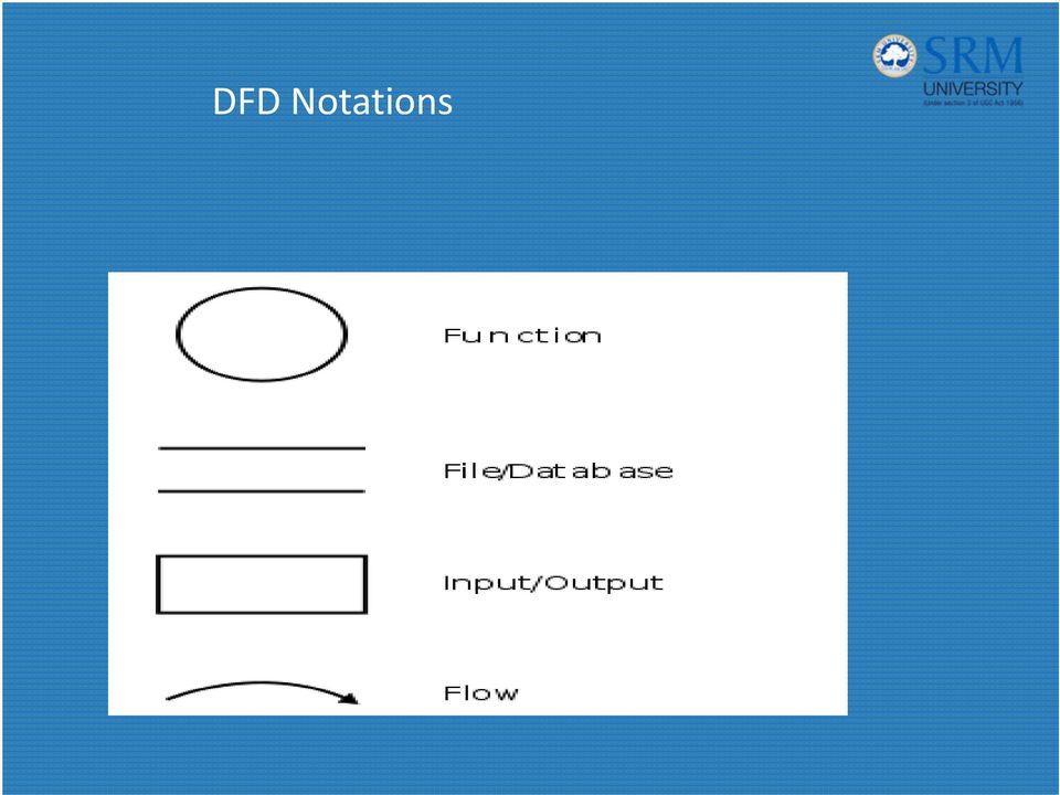
11 DFD Notations A circle (bubble) represents a process or transform that is applied to data (or control). An arrow represents one or more data items (data objects). All arrows on a data flow diagram should be labeled. The double line represents a data store stored information that is used by the software.

12 Data Flow Diagram

13 PSPEC DFD graphical notation must be augmented with descriptive text. A process specification (PSPEC) can be used to specify the processing details implied by a bubble within a DFD. The process specification describes the input to a function, the algorithm that is applied to transform the input, and the output that is produced. In addition, the PSPEC indicates Restrictions and limitations imposed on the process Performance characteristics that are relevant to the process Design constraints that may influence the way in which the process will be implemented.

14 Ward and Mellor Extensions Ward and Mellor extend basic structured analysis notation to accommodate the following demands imposed by a real time system: Information flow is gathered or produced on a time continuous basis. Control information is passed throughout the system and associated control processing.

15 Limitations on Conventional Notation Conventional data flow notation does not make a distinction between discrete data and timecontinuous data To adequately model a real time system, structured analysis notation must be available for time continuous data and event processing. The double headed arrow is used to represent time continuous flow and a single headed arrow is used to indicate discrete data flow.

16

17 A specialized notation for representing event flows and control processing has been developed. Data flow is represented using a solid arrow. Control flow is represented using a dashed arrow. A process that handles only control flows, called a control process, is represented using a dashed bubble.

18 Data and Control Flows
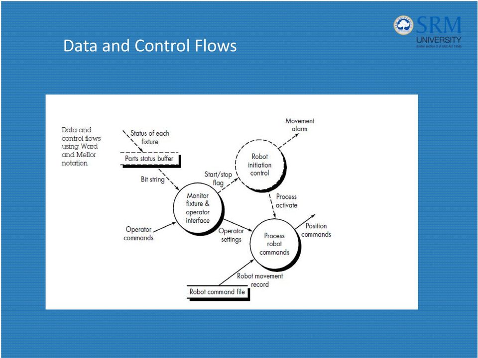
19 Hatley and Pirbhai Extensions The CFD contains the same processes as the DFD, but shows control flow, rather than data flow. Instead of representing control processes directly within the flow model, a notational reference (a solid bar) to a control specification (CSPEC) is used. Data flow diagrams are used to represent data and the processes that manipulate it. Control flow diagrams show how events flow among processes and illustrate those external events that cause various processes to be activated. The process model is "connected" to the control model through data conditions. The control model is "connected" to the process model through process activation information contained in the CSPEC.

20 Data Models and Control Models

21
22 Guidelines for DFD 1. The level 0 data flow diagram should depict the software/system as a single bubble; 2. Primary input and output should be carefully noted; 3. Refinement should begin by isolating candidate processes, data objects, and stores to be represented at the next level; 4. All arrows and bubbles should be labeled with meaningful names; 5. Information flow continuity must be maintained from level to level 6. One bubble at a time should be refined.
23 Sample DFD and CFD SafeHome software enables the homeowner to configure the security system when it is installed, monitors all sensors connected to the security system, and interacts with the homeowner through a keypad and function keys contained in the SafeHome control panel During installation, the SafeHome control panel is used to "program" and configure the system. Each sensor is assigned a number and type, a master password is programmed for arming and disarming the system, and telephone number(s) are input for dialing when a sensor event occurs. When a sensor event is recognized, the software invokes an audible alarm attached to the system. After a delay time that is specified by the homeowner during system configuration activities, the software dials a telephone number of a monitoring service, provides information about the location, reporting the nature of the event that has been detected. The telephone number will be redialed every 20 seconds until telephone connection is obtained. All interaction with SafeHome is managed by a user interaction subsystem that reads input provided through the keypad and function keys, displays prompting messages on the LCD display, displays system status information on the LCD display.
24 Level 0 DFD
25 Level 1 DFD
26 Level 2 DFD
27 Guidelines for CFD Remove all data flow arrows in DFD. Add events and control items (dashed arrows) to the diagram Add a "window" (a vertical bar) into the control specification Event Selection An event or control item is implemented as a Boolean value (e.g., true or false, on or off, 1 or 0) A discrete list of conditions (empty, jammed, full). To select potential candidate events, the following guidelines are suggested: List all sensors that are "read" by the software. List all interrupt conditions. List all "switches" that are actuated by an operator. List all data conditions. Review all "control items" as possible CSPEC inputs/outputs. Describe the behavior of a system by identifying its states; identify how each state is reached and define the transitions between states.
28 Level 1 CFD for Safe Home
29 School of Computing, Department 29 bibliography Software Engineering, Roger Pressman, Fifth Edition Software Engineering, Ian Sommerville, Sixth Edition
30 School of Computing, Department 30 Review questions How is cardinality different from Modality? What is a DFD? What are the notations used in a DFD? What is a ER diagram used for?
Software Design. Design (I) Software Design Data Design. Relationships between the Analysis Model and the Design Model
 Software Design Data Design. Relationships between the Analysis Model and the Design Model") Software Design Design (I) Software Design is a process through which requirements are translated into a representation of software. Peter Lo CS213 Peter Lo 2005 1 CS213 Peter Lo 2005 2 Relationships between
Software Design Design (I) Software Design is a process through which requirements are translated into a representation of software. Peter Lo CS213 Peter Lo 2005 1 CS213 Peter Lo 2005 2 Relationships between
[1] http://en.wikipedia.org/wiki/first-mover_advantage [2] http://www.acunote.com
![[1] http://en.wikipedia.org/wiki/first-mover_advantage [2] http://www.acunote.com](/thumbs/24/2883514.jpg "[1] http://en.wikipedia.org/wiki/first-mover_advantage [2] http://www.acunote.com") -Gene Sher Software Development Processes: Those in engineering and science will sooner or later either be members of teams solving some large project, or be managing teams solving some large project.
-Gene Sher Software Development Processes: Those in engineering and science will sooner or later either be members of teams solving some large project, or be managing teams solving some large project.
2 SYSTEM DESCRIPTION TECHNIQUES
 2 SYSTEM DESCRIPTION TECHNIQUES 2.1 INTRODUCTION Graphical representation of any process is always better and more meaningful than its representation in words. Moreover, it is very difficult to arrange
(Refer Slide Time 00:56)
") Software Engineering Prof.N. L. Sarda Computer Science & Engineering Indian Institute of Technology, Bombay Lecture-12 Data Modelling- ER diagrams, Mapping to relational model (Part -II) We will continue
Software Engineering Prof.N. L. Sarda Computer Science & Engineering Indian Institute of Technology, Bombay Lecture-12 Data Modelling- ER diagrams, Mapping to relational model (Part -II) We will continue
Requirements Analysis Concepts & Principles. Instructor: Dr. Jerry Gao
 Requirements Analysis Concepts & Principles Instructor: Dr. Jerry Gao Requirements Analysis Concepts and Principles - Requirements Analysis - Communication Techniques - Initiating the Process - Facilitated
CS 487. Week 8. Reference: 1. Software engineering, roger s. pressman. Reading: 1. Ian Sommerville, Chapter 3. Objective:
 CS 487 Week 8 Reading: 1. Ian Sommerville, Chapter 3. Objective: 1. To check the understandibility of the students in life cycle and process model for development of a software product. 2. To check if
SOFTWARE ENGINEERING IT 0301 Semester V B.Nithya,G.Lakshmi Priya Asst Professor SRM University, Kattankulathur
 SOFTWARE ENGINEERING IT 0301 Semester V B.Nithya,G.Lakshmi Priya Asst Professor SRM University, Kattankulathur School of Computing, Department of IT 1 2 Process What is it? A series of predictable steps
Classnotes 5: 1. Design and Information Flow A data flow diagram (DFD) is a graphical technique that is used to depict information flow, i.e.
 is a graphical technique that is used to depict information flow, i.e.") Classnotes 5: 1. Design and Information Flow A data flow diagram (DFD) is a graphical technique that is used to depict information flow, i.e., a representation of information as a continuous flow that
Classnotes 5: 1. Design and Information Flow A data flow diagram (DFD) is a graphical technique that is used to depict information flow, i.e., a representation of information as a continuous flow that
Chapter 6. Data-Flow Diagrams
 Chapter 6. Data-Flow Diagrams Table of Contents Objectives... 1 Introduction to data-flow diagrams... 2 What are data-flow diagrams?... 2 An example data-flow diagram... 2 The benefits of data-flow diagrams...
Software Engineering Question Bank
 Software Engineering Question Bank 1) What is Software Development Life Cycle? (SDLC) System Development Life Cycle (SDLC) is the overall process of developing information systems through a multi-step
LECTURE 11: PROCESS MODELING
 LECTURE 11: PROCESS MODELING Outline Logical modeling of processes Data Flow Diagram Elements Functional decomposition Data Flows Rules and Guidelines Structured Analysis with Use Cases Learning Objectives
Hotel Management System
 A Seminar report On Hotel Management System Submitted in partial fulfillment of the requirement for the award of degree Of MBA SUBMITTED TO: SUBMITTED BY: Preface I have made this report file on the topic
Understanding Data Flow Diagrams Donald S. Le Vie, Jr.
 Understanding Flow Diagrams Donald S. Le Vie, Jr. flow diagrams (DFDs) reveal relationships among and between the various components in a program or system. DFDs are an important technique for modeling
Data Flow Diagram (DFD) Tutorial Written Date : January 27, 2012
 Tutorial Written Date : January 27, 2012") Written Date : January 27, 2012 What is a data flow diagram (DFD)? Data Flow Diagrams (DFD) helps us in identifying existing business processes. It is a technique we benefit from particularly before we
Written Date : January 27, 2012 What is a data flow diagram (DFD)? Data Flow Diagrams (DFD) helps us in identifying existing business processes. It is a technique we benefit from particularly before we
Chapter 4: Tools of Modern Systems Analysis
 Just Enough Structured Analysis Chapter 4: Tools of Modern Systems Analysis Nature has... some sort of arithmetical-geometrical coordinate system, because nature has all kinds of models. What we experience
Module 7. Software Engineering Issues. Version 2 EE IIT, Kharagpur 1
 Module 7 Software Engineering Issues Version 2 EE IIT, Kharagpur 1 Lesson 36 Software Design Part 1 Version 2 EE IIT, Kharagpur 2 Specific Instructional Objectives At the end of this lesson, the student
Collated Food Requirements. Received orders. Resolved orders. 4 Check for discrepancies * Unmatched orders
 Introduction to Data Flow Diagrams What are Data Flow Diagrams? Data Flow Diagrams (DFDs) model that perspective of the system that is most readily understood by users the flow of information around the
How To Develop Software
 Software Engineering Prof. N.L. Sarda Computer Science & Engineering Indian Institute of Technology, Bombay Lecture-4 Overview of Phases (Part - II) We studied the problem definition phase, with which
Functional Data Flow Diagrams. Outline
 Introduction to Database Systems Functional s Ling Liu Associate Professor College of Computing, Georgia Tech 1 Outline This week: Exercise of Relational Algebra Techniques for ming Next Week Midterm 1
1. Process Modeling. Process Modeling (Cont.) Content. Chapter 7 Structuring System Process Requirements
 Content. Chapter 7 Structuring System Process Requirements") Content Chapter 7 Structuring System Process Requirements Understand the logical (&physical) process modeling by using data flow diagrams (DFDs) Draw DFDs & Leveling Balance higher-level and lower-level
Content Chapter 7 Structuring System Process Requirements Understand the logical (&physical) process modeling by using data flow diagrams (DFDs) Draw DFDs & Leveling Balance higher-level and lower-level
Student Attendance Through Mobile Devices
 Student Attendance Through Mobile Devices Anurag Rastogi Kirti Gupta Department of Computer Science and Engineering National Institute of Technology Rourkela Rourkela-769 008, Odisha, India Student Attendance
Developing Entity Relationship Diagrams (ERDs)
") Developing Entity Relationship Diagrams (ERDs) Introduction This document seeks to give expanded explanation and examples of how to produce entity relationship diagrams. It is based on material adapted
Developing Entity Relationship Diagrams (ERDs) Introduction This document seeks to give expanded explanation and examples of how to produce entity relationship diagrams. It is based on material adapted
NetworX TM NX-8E Alarm Panel. Application Note. NetworX NX-8E. 1.0 The NetworX NX-8E Alarm Panel
 The PXL-510 tiger controller can be connected with the NetworX 1 NX-8E Alarm panel to allow arming and disarming of the alarm system by using the alarm panel keypad, using a wireless Wiegand device, or
Unit 2.1. Data Analysis 1 - V2.0 1. Data Analysis 1. Dr Gordon Russell, Copyright @ Napier University
 Data Analysis 1 Unit 2.1 Data Analysis 1 - V2.0 1 Entity Relationship Modelling Overview Database Analysis Life Cycle Components of an Entity Relationship Diagram What is a relationship? Entities, attributes,
Process Modeling Notations and Workflow Patterns
 Process Modeling Notations and Workflow Patterns Stephen A. White, IBM Corp., United States ABSTRACT The research work of Wil van der Aalst, Arthur ter Hofstede, Bartek Kiepuszewski, and Alistair Barros
MODULE 5 DATA FLOW DIAGRAMS
 MODULE 5 DATA FLOW DIAGRAMS Learning Units 5.1 Developing Data Flow Diagrams(DFD) a) What are DFDs? b) Symbols used in DFD c) Rules of data flow d) Good style in drawing DFD 5.2 Describing systems with
Modern Systems Analysis and Design
 Modern Systems Analysis and Design Prof. David Gadish Structuring System Data Requirements Learning Objectives Concisely define each of the following key data modeling terms: entity type, attribute, multivalued
Table of Contents. CHAPTER 1 Web-Based Systems 1. CHAPTER 2 Web Engineering 12. CHAPTER 3 A Web Engineering Process 24
 Table of Contents CHAPTER 1 Web-Based Systems 1 The Web 1 Web Applications 2 Let s Introduce a Case Study 3 Are WebApps Really Computer Software? 4 Are the Attributes of WebApps Different from the Attributes
Types of UML Diagram. UML Diagrams 140703-OOAD. Computer Engineering Sem -IV
 140703-OOAD Computer Engineering Sem -IV Introduction to UML - UML Unified Modeling Language diagram is designed to let developers and customers view a software system from a different perspective and
Database Design Process
 Database Design Process Entity-Relationship Model From Chapter 5, Kroenke book Requirements analysis Conceptual design data model Logical design Schema refinement: Normalization Physical tuning Problem:
Objectives After completion of study of this unit you should be able to:
 Data Flow Diagram Tutorial Objectives After completion of study of this unit you should be able to: Describe the use of data flow diagrams Produce a data flow diagram from a given case study including
Database Design Process
 Entity-Relationship Model Chapter 3, Part 1 Database Design Process Requirements analysis Conceptual design data model Logical design Schema refinement: Normalization Physical tuning 1 Problem: University
CHAPTER 7 Expected Outcomes
 CHAPTER 7 SYSTEM DESIGN Expected Outcomes Able to know database design Able to understand designing form and report Able to know designing interfaces System Design A process of transforming from logical
Announcements. SE 1: Software Requirements Specification and Analysis. Review: Use Case Descriptions
 Announcements SE 1: Software Requirements Specification and Analysis Lecture 4: Basic Notations Nancy Day, Davor Svetinović http://www.student.cs.uwaterloo.ca/ cs445/winter2006 uw.cs.cs445 Send your group
Data Analysis 1. SET08104 Database Systems. Copyright @ Napier University
 Data Analysis 1 SET08104 Database Systems Copyright @ Napier University Entity Relationship Modelling Overview Database Analysis Life Cycle Components of an Entity Relationship Diagram What is a relationship?
Software Engineering UNIT -1 OVERVIEW
 UNIT -1 OVERVIEW The economies of ALL developed nations are dependent on software. More and more systems are software controlled. Software engineering is concerned with theories, methods and tools for
Chapter 3. Data Flow Diagrams
 Chapter 3. Data Flow Diagrams Table of Contents Objectives... 1 Introduction to Data Flow Diagrams... 2 What are Data Flow Diagrams?... 2 An example Data Flow Diagram... 2 The benefits of Data Flow Diagrams...
Investigate Requirements for Software Solutions
 Unit 29: Investigate Requirements for Software Solutions Learning Outcomes A candidate following a programme of learning leading to this unit will be able to: Gather and analyse appropriate and relevant
Using UML Part Two Behavioral Modeling Diagrams
 UML Tutorials Using UML Part Two Behavioral Modeling Diagrams by Sparx Systems All material Sparx Systems 2007 Sparx Systems 2007 Page 1 Trademarks Object Management Group, OMG, Unified Modeling Language,
Programmable Logic Controllers Definition. Programmable Logic Controllers History
 Definition A digitally operated electronic apparatus which uses a programmable memory for the internal storage of instructions for implementing specific functions such as logic, sequencing, timing, counting,
The Business Process Model
 The Business Process Model by Sparx Systems All material Sparx Systems 2007 Sparx Systems 2007 Page: 1 Table of Contents INTRODUCTION...3 BUSINESS PROCESS MODELING NOTATION (BPMN)...4 FLOW ELEMENTS...4
Firmware version: 1.10 Issue: 7 AUTODIALER GD30.2. Instruction Manual
 Firmware version: 1.10 Issue: 7 AUTODIALER GD30.2 Instruction Manual Firmware version: 2.0.1 Issue: 0.6 Version of the GPRS transmitters configurator: 1.3.6.3 Date of issue: 07.03.2012 TABLE OF CONTENTS
1 Class Diagrams and Entity Relationship Diagrams (ERD)
") 1 Class Diagrams and Entity Relationship Diagrams (ERD) Class diagrams and ERDs both model the structure of a system. Class diagrams represent the dynamic aspects of a system: both the structural and behavioural
1 Class Diagrams and Entity Relationship Diagrams (ERD) Class diagrams and ERDs both model the structure of a system. Class diagrams represent the dynamic aspects of a system: both the structural and behavioural
The following information can be output as speech: status of the teacher / student connection. time markers of the timers.
 1 V2 software 1.1 Update from V1 to V2 Additional files must be installed when updating from software version 1 to version 2. In version 2.xx, the volume settings are stored in the model memory. The volume
GSM Autodialer Professional GJD700 Speech & Text Autodialer
 Text Edit message GSM Autodialer Professional GJD700 Speech & Text Autodialer Introduction The GSM Autodialer Professional works in conjunction with standard alarm systems and makes use of your preferred
The University of Colorado at Denver and Health Sciences Center Robotics Society presents: PUMA
 The University of Colorado at Denver and Health Sciences Center Robotics Society presents: PUMA Required Faculty Advisor Statement I certify that the engineering design of the updated vehicle described
Project management. Organizing, planning and scheduling software projects
 Project management Organizing, planning and scheduling software projects Ian Sommerville 1995 Software Engineering, 5th edition. Chapter 3 Slide 1 Objectives To introduce software project management and
Goals of the Unit. spm - 2014 adolfo villafiorita - introduction to software project management
 Project Scheduling Goals of the Unit Making the WBS into a schedule Understanding dependencies between activities Learning the Critical Path technique Learning how to level resources!2 Initiate Plan Execute
Nicholas Mezei CSCI 6448 OOA&D Homework #3: Use Cases. Use Case Diagram: Home Security System. Alarm System
 Nicholas Mezei CSCI 6448 OOA&D Homework #3: Use Cases Use Case Diagram: Home Security System Alarm System Use Case #1: Issue Smoke Alarm Primary Actor: Smoke detector Goal in Context: Smoke detector detects
CSC 342 Semester I: 1425-1426H (2004-2005 G)
") CSC 342 Semester I: 1425-1426H (2004-2005 G) Software Engineering Systems Analysis: Requirements Structuring Context & DFDs. Instructor: Dr. Ghazy Assassa Software Engineering CSC 342/Dr. Ghazy Assassa
CSC 342 Semester I: 1425-1426H (2004-2005 G) Software Engineering Systems Analysis: Requirements Structuring Context & DFDs. Instructor: Dr. Ghazy Assassa Software Engineering CSC 342/Dr. Ghazy Assassa
IBM Business Process Manager Version 8 Release 5. Hiring Tutorial IBM
 IBM Business Process Manager Version 8 Release 5 Hiring Tutorial IBM Note Before using this information and the product it supports, read the information in Notices on page 95. This edition applies to
MAHATMA GANDHI UNIVERSITY SCHOOL OF DISTANCE EDUCATION (MGU CBCSS UG SDE 2012)
") MAHATMA GANDHI UNIVERSITY SCHOOL OF DISTANCE EDUCATION (MGU CBCSS UG SDE 2012) B.Sc Computer Science Semester V BCS 502 Core-19: System Analysis &Design Multiple Choice questions 1... includes review of
MAHATMA GANDHI UNIVERSITY SCHOOL OF DISTANCE EDUCATION (MGU CBCSS UG SDE 2012) B.Sc Computer Science Semester V BCS 502 Core-19: System Analysis &Design Multiple Choice questions 1... includes review of
Foundations for Systems Development
 Foundations for Systems Development ASSIGNMENT 1 Read this assignment introduction. Then, read Chapter 1, The Systems Development Environment, on pages 2 25 in your textbook. What Is Systems Analysis and
6-1. Process Modeling
 6-1 Process Modeling Key Definitions Process model A formal way of representing how a business system operates Illustrates the activities that are performed and how data moves among them Data flow diagramming
Requirements engineering
 Learning Unit 2 Requirements engineering Contents Introduction............................................... 21 2.1 Important concepts........................................ 21 2.1.1 Stakeholders and
Chapter 7: Structuring System Process Requirements
 Chapter 7: Structuring System Process Requirements Multiple Choice Questions 1. Data flow diagrams that concentrate on the movement of data between processes are referred to as: a. process models b. data
Database Design. Marta Jakubowska-Sobczak IT/ADC based on slides prepared by Paula Figueiredo, IT/DB
 Marta Jakubowska-Sobczak IT/ADC based on slides prepared by Paula Figueiredo, IT/DB Outline Database concepts Conceptual Design Logical Design Communicating with the RDBMS 2 Some concepts Database: an
Process Modelling from Insurance Event Log
 Process Modelling from Insurance Event Log P.V. Kumaraguru Research scholar, Dr.M.G.R Educational and Research Institute University Chennai- 600 095 India Dr. S.P. Rajagopalan Professor Emeritus, Dr. M.G.R
fakultät für informatik informatik 12 technische universität dortmund Data flow models Peter Marwedel Informatik 12 TU Dortmund Germany
 12 Data flow models Peter Marwedel Informatik 12 TU Dortmund Germany Models of computation considered in this course Communication/ local computations Communicating finite state machines Data flow model
Object Oriented Programming. Risk Management
 Section V: Object Oriented Programming Risk Management In theory, there is no difference between theory and practice. But, in practice, there is. - Jan van de Snepscheut 427 Chapter 21: Unified Modeling
Data Flow Diagram (DFD) Tutorial Written Date : January 27, 2012
 Tutorial Written Date : January 27, 2012") Written Date : January 27, 2012 What is a data flow diagram (DFD)? Data Flow Diagrams (DFD) helps us in identifying existing business processes. It is a technique we benefit from particularly before we
Written Date : January 27, 2012 What is a data flow diagram (DFD)? Data Flow Diagrams (DFD) helps us in identifying existing business processes. It is a technique we benefit from particularly before we
LCD -based Intelligent Burglar Alarm System. User Guide. Ver 2.0
 LCD -based Intelligent Burglar Alarm System User Guide Ver 2.0 Table of Content 1. Introduction... 2 1.1 General Description... 3 1.2 System Features... 3 2. Anatomy of the LCD-based Intelligence Burglar
Assignment # 2: Design Patterns and GUIs
 CSUS COLLEGE OF ENGINEERING AND COMPUTER SCIENCE Department of Computer Science CSc 133 Object-Oriented Computer Graphics Programming Spring 2014 John Clevenger Assignment # 2: Design Patterns and GUIs
Data Flow Diagram. Data Flow Diagrams (DFDs)
") Data Flow Diagram Introduction The three most important modeling techniques used in analysing and building information systems are: Data Flow Diagramming (DFDs), Logical Data Structure modelling (LDSs),
Data Flow Diagram Introduction The three most important modeling techniques used in analysing and building information systems are: Data Flow Diagramming (DFDs), Logical Data Structure modelling (LDSs),
Title: Topic 3 Software process models (Topic03 Slide 1).
.") Title: Topic 3 Software process models (Topic03 Slide 1). Topic 3: Lecture Notes (instructions for the lecturer) Author of the topic: Klaus Bothe (Berlin) English version: Katerina Zdravkova, Vangel Ajanovski
Title: Topic 3 Software process models (Topic03 Slide 1). Topic 3: Lecture Notes (instructions for the lecturer) Author of the topic: Klaus Bothe (Berlin) English version: Katerina Zdravkova, Vangel Ajanovski
Fahad H.Alshammari, Rami Alnaqeib, M.A.Zaidan, Ali K.Hmood, B.B.Zaidan, A.A.Zaidan
 WWW.JOURNALOFCOMPUTING.ORG 85 New Quantitative Study for Dissertations Repository System Fahad H.Alshammari, Rami Alnaqeib, M.A.Zaidan, Ali K.Hmood, B.B.Zaidan, A.A.Zaidan Abstract In the age of technology,
Software Requirements Specification of A University Class Scheduler
 Software Requirements Specification of A University Class Scheduler Deanna M. Needell Jeff A. Stuart Tamara C. Thiel Sergiu M. Dascalu Frederick C. Harris, Jr. Department of Computer Science University
Grade descriptions Computer Science Stage 1
 Stage 1 A B C Accurately uses a wide range of terms and concepts associated with current personal computers, home networking and internet connections. Correctly uses non-technical and a range of technical
Chapter 2: Entity-Relationship Model. E-R R Diagrams
 Chapter 2: Entity-Relationship Model What s the use of the E-R model? Entity Sets Relationship Sets Design Issues Mapping Constraints Keys E-R Diagram Extended E-R Features Design of an E-R Database Schema
DATABASE DESIGN. - Developing database and information systems is performed using a development lifecycle, which consists of a series of steps.
 DATABASE DESIGN - The ability to design databases and associated applications is critical to the success of the modern enterprise. - Database design requires understanding both the operational and business
D-MAX WEB GUIDE CONTROLLER WITH OPERATOR INTERFACE PANEL QUICK START SETUP MANUAL
 1/1 D-MAX.D1 1A Manual S1 D-MAX OPERATOR INTERFACE (Application Home Screen Is Shown) D-MAX CONTROLLER 04/14/2008 2008 Fife Corporation. All rights reserved. Figure Sheet 2-249 This page is intentionally
AUTODIALLER / QUICKDIALLER - SA132
 AUTODIALLER / QUICKDIALLER - SA132 INSTRUCTION LEAFLET ENGLISH www.thermomax-group.com CONTENTS 1 SETUP AT A GLANCE... 2 2 FOREWORD....... 3 3 INSTALLATION...... 4 4 KEYPAD AND INDICATORS...... 5 SETTING
SOFTWARE DESIGN TECHNIQUES. Nagalaxmi Telkar CSCI 5828 Presentation Slides
 SOFTWARE DESIGN TECHNIQUES Nagalaxmi Telkar CSCI 5828 Presentation Slides CONTENTS Introduction Software Design Life Cycle Software Design Process Tackling Design Problems Architectural Design Abstract
Project management. Organizing, planning and scheduling software projects. Objectives. Chapter 3. Chapter 3 Project Management. Learning Objective
 Chapter 3 Chapter 3 Project Management Learning Objective...to give an appreciation for and to introduce project management and to place it into context and give some of the fundamentals to project management
IT3205: Fundamentals of Software Engineering (Compulsory)
") INTRODUCTION : Fundamentals of Software Engineering (Compulsory) This course is designed to provide the students with the basic competencies required to identify requirements, document the system design
INTRODUCTION : Fundamentals of Software Engineering (Compulsory) This course is designed to provide the students with the basic competencies required to identify requirements, document the system design
AGRI-ALERT 800T / AGRI-ALERT 800 ALARM SYSTEM USER MANUAL
 AGRI-ALERT 800T / AGRI-ALERT 800 ALARM SYSTEM USER MANUAL Manufacturer: Viatron Electronics 3514 1st Street, St-Hubert (Quebec) Canada J3Y 8Y5 WARNING: the warranty can be void if the Agri-Alert 800T or
Roadmap. Software Engineering. Software Engineering. Project Life Cycle. Database. Project Lifecycle
 Database Project Lifecycle Philippe Bonnet, 2006 2 Software Engineering The implementation of a database application is a significant engineering endeavor The project must complete On time On budget The
CHAPTER 3. Data Modeling and Database Design- Part1
 CHAPTER 3 Data Modeling and Database Design- Part1 INTRODUCTION Questions to be addressed in this chapter include: What is the purpose of documentation? Why do accountants need to understand documentation?
Overview. System Definition Webster s Dictionary. System Engineering Hierarchy. System Engineering. Computer-Based Systems [PRE2005]
![Overview. System Definition Webster s Dictionary. System Engineering Hierarchy. System Engineering. Computer-Based Systems [PRE2005]](/thumbs/26/9053186.jpg "Overview. System Definition Webster s Dictionary. System Engineering Hierarchy. System Engineering. Computer-Based Systems [PRE2005]") IF2261 Software Engineering Engineering Program Studi Teknik Informatika STEI ITB Overview Before software can be engineered: the system it is part of must be understood, the overall objective of the system
IF2261 Software Engineering Engineering Program Studi Teknik Informatika STEI ITB Overview Before software can be engineered: the system it is part of must be understood, the overall objective of the system
Project management: an SE Perspective
 Project management: an SE Perspective Ian Sommerville 2004 Software Engineering, 7th edition. Chapter 5 Slide 1 Objectives To explain the main tasks undertaken by project managers To introduce software
SCHEMAS AND STATE OF THE DATABASE
 SCHEMAS AND STATE OF THE DATABASE Schema the description of a database specified during database design relatively stable over time Database state the data in a database at a particular moment the set
3. SCHEDULING THE MOST IMPORTANT PHASE PLANNING ACTIVITY. 3.1 Project Management Software Does it Really Do That?
 3. SCHEDULING THE MOST IMPORTANT PHASE PLANNING ACTIVITY 3.1 Project Management Software Does it Really Do That? Not really it doesn t do any management that takes a talented human like you! A betternamed
Data Modeling Basics
 Information Technology Standard Commonwealth of Pennsylvania Governor's Office of Administration/Office for Information Technology STD Number: STD-INF003B STD Title: Data Modeling Basics Issued by: Deputy
Designing a Home Alarm using the UML. And implementing it using C++ and VxWorks
 Designing a Home Alarm using the UML And implementing it using C++ and VxWorks M.W.Richardson I-Logix UK Ltd. markr@ilogix.com This article describes how a simple home alarm can be designed using the UML
Chapter 7 Data Modeling Using the Entity- Relationship (ER) Model
 Model") Chapter 7 Data Modeling Using the Entity- Relationship (ER) Model Copyright 2011 Pearson Education, Inc. Publishing as Pearson Addison-Wesley Chapter 7 Outline Using High-Level Conceptual Data Models for
Chapter 7 Data Modeling Using the Entity- Relationship (ER) Model Copyright 2011 Pearson Education, Inc. Publishing as Pearson Addison-Wesley Chapter 7 Outline Using High-Level Conceptual Data Models for
Algorithm & Flowchart & Pseudo code. Staff Incharge: S.Sasirekha
 Algorithm & Flowchart & Pseudo code Staff Incharge: S.Sasirekha Computer Programming and Languages Computers work on a set of instructions called computer program, which clearly specify the ways to carry
Object Oriented Design
 Object Oriented Design Kenneth M. Anderson Lecture 20 CSCI 5828: Foundations of Software Engineering OO Design 1 Object-Oriented Design Traditional procedural systems separate data and procedures, and
1 INTRODUCTION TO SYSTEM ANALYSIS AND DESIGN
 1 INTRODUCTION TO SYSTEM ANALYSIS AND DESIGN 1.1 INTRODUCTION Systems are created to solve problems. One can think of the systems approach as an organized way of dealing with a problem. In this dynamic
Copyright 2009 Bahn, D., Tang, H. & Yardley, A. All Rights Reserved. ISBN: 978-1-936203-05-5. Systems Analysis and Design Learning Module Series #3
 Systems Analysis and Design Learning Module Series #3 Document version Data Flow Diagrams Part 1 Creating an Intersection Table in a Relational Database Overview In this tutorial we will explain the basic
INTRODUCTION TO BUSINESS PROCESS MODELING NOTATION BPMN 1.2 AND BPMN 2.0
 INTRODUCTION TO BUSINESS PROCESS MODELING NOTATION BPMN 1.2 AND BPMN 2.0 Email: {goliva,gerosa}@ime.usp.br / Twitter: @golivax Agenda 2 Introduction to Business Processes BPMN 1.2 Introduction Elements
Introduction to Systems Analysis and Design
 Introduction to Systems Analysis and Design What is a System? A system is a set of interrelated components that function together to achieve a common goal. The components of a system are called subsystems.
Table Of Contents. System Monitoring... 14 System Monitoring Display...14 Monitoring Zones...15 About Areas (partitions)...15 Area Status Display...
...15 Area Status Display...") Quick Start Table Of Contents Getting Started... 2 NEware Editions...2 Installing NEware...3 Installing Languages...3 Connecting to NEware...3 Changing Your IP100 Password...4 User Codes... 5 Master Feature...5
Quick Start Table Of Contents Getting Started... 2 NEware Editions...2 Installing NEware...3 Installing Languages...3 Connecting to NEware...3 Changing Your IP100 Password...4 User Codes... 5 Master Feature...5
Lecture 12: Entity Relationship Modelling
 Lecture 12: Entity Relationship Modelling The Entity-Relationship Model Entities Relationships Attributes Constraining the instances Cardinalities Identifiers Generalization 2004-5 Steve Easterbrook. This
OVERVIEW OF THE TELEGUARD HOME SECURITY SYSTEM
 OVERVIEW OF THE TELEGUARD HOME SECURITY SYSTEM 12. WIDE RANGE OF POTENTIAL INPUT DEVICES PIR s, Smoke Alarms, Emergency Transmitters, Environmental / Gas Leak Sensors, Break-in or Inactivity Detectors
ISSUES OF STRUCTURED VS. OBJECT-ORIENTED METHODOLOGY OF SYSTEMS ANALYSIS AND DESIGN
 ISSUES OF STRUCTURED VS. OBJECT-ORIENTED METHODOLOGY OF SYSTEMS ANALYSIS AND DESIGN Mohammad A. Rob, University of Houston-Clear Lake, rob@cl.uh.edu ABSTRACT In recent years, there has been a surge of
Software Engineering. Software Processes. Based on Software Engineering, 7 th Edition by Ian Sommerville
 Software Engineering Software Processes Based on Software Engineering, 7 th Edition by Ian Sommerville Objectives To introduce software process models To describe three generic process models and when
How To Write A Diagram
 Data Model ing Essentials Third Edition Graeme C. Simsion and Graham C. Witt MORGAN KAUFMANN PUBLISHERS AN IMPRINT OF ELSEVIER AMSTERDAM BOSTON LONDON NEW YORK OXFORD PARIS SAN DIEGO SAN FRANCISCO SINGAPORE
YOUR CONTROL PANEL PANEL
 YOUR CONTROL PANEL PANEL To change your pass code, please contact Frontpoint Support at: 877-602-5276 support@frontpointsecurity.com Frontpoint Support: 877-602-5276 The Control Panel: System Codes After
Software Engineering. Software Development Process Models. Lecturer: Giuseppe Santucci
 Software Engineering Software Development Process Models Lecturer: Giuseppe Santucci Summary Modeling the Software Process Generic Software Process Models Waterfall model Process Iteration Incremental
AD-01 Slave Auto Dialer. Owner s Manual
 AD-01 Slave Auto Dialer Owner s Manual AD-01 Slave Manual.indd 1 10/15/2009 10:20:44 AM 2 AD-01 Slave Manual.indd 2 10/15/2009 10:20:44 AM Features: Programmable entry/exit delay time; select up to 9 (32