(12) United States Patent
|
|
|
- Winifred Allen
- 10 years ago
- Views:
Transcription
1 US B2 (12) United States Patent (10) Patent N0.: US 6,582,087 B2 Whitehead et al. (45) Date of Patent: Jun. 24, 2003 (54) EXTENDABLE EXTERIOR REARVIEW D285,549 S 9/1986 Haack..... D12/187 MIRROR ASSEMBLY FOR VEHICLES 4,711,538 A 12/1987 Ohs et al /604 4,730,913 A 3/1988 Boothe /604 (75) Inventors: Peter J. Whitehead, Holland, MI (US); _,, 2 gléitehliad r ane bin gui/h 4,793,582 A 12/1988 Bronstein et al /486 ' 66 an 4,815,836 A 3/1989 Byers et al /604 (Us) 4,892,401 A 1/1990 Kitridge et al /626 4,907,871 H /639 (73) Assigneei Donnell) C0FP Fati I1>H011an MI 4,911,545 A 3/1990 Miller.. 350/604 (Us) 4,921,337 A 5/1990 H /604 4,998,812 A 3/1991 Hou /604 ( * ) Notice: Subject to any disclaimer, the term of this 5,028,029 A 7/1991 Beck et al. 248/479 patent is extended or adjusted under 35 5,061,056 A 10/1991 You /872 U_S_C_ 154(1)) by () days_ 5,096,283 A 3/1992 Croteau /865 D331,216 S 11/1992 McGouldrick.. D12/187 _ 5,217,197 A 6/1993 SpitZer /479 (21) APP1-N ~- 10/ ,292,100 A 3/1994 Byers et al /480 (22) Filed: May (List continued on next page.) (65) Pm Pubhcatlo Data FOREIGN PATENT DOCUMENTS US 2002/ A1 Oct. 3, 2002 CA /1990 Related U'S' Apphcatlon Data Primary Examiner l\/lohammad Sikder (63) Continuation of application No. 09/840,528,?led on Apr. (74) Attorney Agent Or Flrm van Dyke Gardner Lmn & 23, 2001, now Pat. No. 6,390,635, which is a division of Burkhart LLP application No. 09/573,502,?led on May 16, 2000, now Pat. No. 6,239,928, which is a continuation-in-part of application (57) ABSTRACT No. 09/399,875,?led on Sep. 20, 1999, now Pat. No An extendable exterior rearview mirror assembly includes a mounting bracket, a mirror subassembly, and a support (51) Int. c G02B 7/182 Which is Supported by the mounting brackét- The mirror (52) US. Cl /841' 359/843' 359/871' subassembly 15 Supported by the Support and 15 mounted for 359/872 selective movement along the support arm to one of a (58) Field of Search 359/ plurality of viewing positions. The mirror subassembly ? includes a housing, a re?ective element, and an actuator 24 8/ g ; which supports the re?ective element on a forward facing wall of the housing. The rearview mirror assembly further (56) References Cited includes a clamping assembly which provides a force to urge frictional engagement between the housing and the support U,S, PATENT DOCUMENTS to limit movement of the mirror subassembly along the support. In preferred form, the support extends into the 2 5:16:05 """""""""""" housing and frictionally engages an exterior surface of the 3:420:490 A 1/1969 Malachowski /486 forward facmg Wan 4,135,694 A 1/1979 Stegenga et al /478 4,315,614 A 2/1982 Stegenga et al /479 1 Claim, 16 Drawing Sheets B 20 kba \ ~48 T l a "*2 Ill/llljl/I/l/IlI/I/l/I/lllllllll/I/l/l/l 52a ) 133/ e o O LH'C 5.1..,., \3 as.,.,,.,- : a 1181) % M O a
 4,892,401 A 1/1990 Kitridge et al... 350/626 4,907,871 H................. 350/639 (73) Assigneei Donnell) C0FP Fati I1>H011an MI 4,911,545 A 3/1990 Miller.")
2 US 6,582,087 B2 Page 2 US. PATENT DOCUMENTS 5,572,376 A 11/1996 Pace /877 5,432,640 A 7/1995 Gilbert et a / ;: 2 2/133; id zlntant a lllt """"""" " ZZZ/2:: 5,483,385 A 1/ a / 6 er 6 a / 5,489,080 A 2/1996 5,903,402 A 5/1999 Hoek /841 5,513,048 A 4/1996 6,276,805 B1 8/2001 Home et a /841 5,546,239 A 8/1996 Lewis /855 6,276,808 B1 8/2001 F6616 et a /877

3 U.S. Patent Jun. 24, 2003 Sheet 1 0f 16 US 6,582,087 B2 F161

4 U.S. Patent Jun. 24, 2003 Sheet 2 0f 16 US 6,582,087 B2

5 U.S. Patent Jun. 24, 2003 Sheet 3 0f 16 US 6,582,087 B2 s _., I ) 3..2 PHI I II I. i. I1 II \/ Ii r / 2E :1 \ LI III I.01 m

6 U.S. Patent Jun. 24, 2003 Sheet 4 0f 16 US 6,582,087 B2

7
8 U.S. Patent Jun. 24, 2003 Sheet 6 6f 16 US 6,582,087 B2 m3 m3

9 U.S. Patent Jun. 24, 2003 Sheet 7 0f 16 US 6,582,087 B2

10 U.S. Patent Jun. 24, 2003 Sheet 8 0f 16 US 6,582,087 B2 862 a: 876d

11 U.S. Patent Jun. 24, 2003 Sheet 9 0f 16 US 6,582,087 B2 882b b, 88gb

12
13 U.S. Patent Jun. 24, 2003 Sheet 11 0f 16 US 6,582,087 B2 \/.mww/d MW, wmm comm 08 g8 mmm Emma; M555 DUDE NNQ Ohm

14 U.S. Patent Jun. 24, 2003 Sheet 12 0f 16 US 6,582,087 B2 21mm, wmw

15 U.S. Patent Jun. 24, 2003 Sheet 13 0f 16 US 6,582,087 B2 5 0mm 5m 5m Nmm Q SQ

16 U.S. Patent Jun. 24, 2003 Sheet 14 0f 16 US 6,582,087 B2

17 U.S. Patent Jun Sheet 15 0f 16

18 U.S. Patent Jun. 24, 2003 Sheet 16 0f 16 US 6,582,087 B

19 1 EXTENDABLE EXTERIOR REARVIEW MIRROR ASSEMBLY FOR VEHICLES This is a continuation application of Ser. No. 09/840,528,?led Apr. 23, 2001, entitled EXTENDABLE EXTERIOR REARVIEW MIRROR ASSEMBLY FOR VEHICLES, by Peter J. Whitehead, Steven G. Hoek, and Michiel P. van de Ven, now US. Pat. No. 6,390,635, Which is a divisional application Ser. No. 09/573,502,?led May 16, 2000, now US. Pat. No. 6,239,928, Which is a continuation-in-part application of US. Pat. application entitled EXTENDABLE EXTERIOR REARVIEW MIRROR ASSEMBLY FOR VEHICLES, Ser. No. 09/399,875,?led Sep. 20, 1999, now US. Pat. No. 6,116,743, the disclosures of Which are herein incorporated by reference in their entireties. TECHNICAL FIELD AND BACKGROUND OF THE INVENTION The present invention relates to an exterior rearview mirror for mounting on a vehicle and, more particularly, to an extendable exterior rearview mirror for mounting on a vehicle Which can be extended When the vehicle is being used for towing, for example towing a trailer, camper, or the like. Until recently, towing mirrors included a?xed support or frame, Which Was rigidly mounted to the vehicle body, and a re?ective element supported on and spaced from the vehicle body by the support or frame to provide rearview viewing of the towed object. For example, US. Pat. No. 3,119,591 to A. J. Malecki illustrates a typical rigidly mounted towing mirror assembly. HoWever, these?xed extended rearview mirror assemblies increase the Width of the vehicle often hampering normal maneuvering through passages including garage door openings, drive-through services, and the like. Furthermore, they are more vulnerable to being damaged or causing damage than conventional exterior rearview mirrors especially When used by an inex perienced driver. In some cases, the Width of the vehicles Was increased beyond the maximum Width allowed by conventional vehicle transport trucks Which deliver the vehicles to the dealership. Therefore, these mirror assem blies often required installation at the dealership Which ultimately increased the cost of the vehicle. More recently, several extendable exterior rearview mir rors have been developed. For example, in US. Pat. No. 5,513,048 to Chen and US. Pat. No. 5,489,080 to Allen, extendable rearview mirrors are disclosed Which include telescoping members. The position of the mirror subassembly, Which includes a re?ective element and re?ec tive element housing, is?xed in position by threaded fasteners, Which require tools for adjustment. HoWever, these assemblies tend to increase the vibration of the mirror assembly especially When the mirror subassembly is in the outboard position. This increased vibration is particularly problematic in mirror assemblies that incorporate mechani cal or electrical actuators since they increase the Weight of the mirror casing. Other solutions have included providing nesting mirror re?ectors With one of the mirror re?ectors supported in a housing that is extendable from the mirror casing, such as described in US. Pat. No. 4,998,812 and 4,907,871 to Hou. While these assemblies incorporate a single arm mounting arrangement, the assembly is compli cated and requires a dual re?ection system that ultimately increases the cost of the assembly, as Well as the Weight of the mirror casing. Heretofore, commercially available exte rior mirrors have used a twin arm arrangement in order to US 6,582,087 B increase the stiffness of the mounting attachment, such as disclosed in US. Pat. No. 5,483,385 to Boddy. Such twin arms provide support to the mirror casino in a manner that minimizes mirror re?ector vibrations When the vehicle trav els on roads. HoWever, use of such twin arm arrangements dictates a relatively large assembly With multiple mounting components, Which increases material cost and assembly time. Hitherto, use of a single arm extendible mirror assem bly has not met With commercial success because of the reduced stiffness associated With prior art designs Which result in increased vibration. Consequently, there is a need for an extendable rearview mirror assembly that can provide for an extended?eld of view When towing and yet can be retracted to a normal operating position Where it does not hamper maneuverability of the vehicle. In addition, the extendable rearview mirror assembly should have minimal impact on the vibration characteristics of the mirror assembly and be relatively easy to adjust between non-towing and towing positions Without the need for tools. SUMMARY OF THE INVENTION Accordingly, the present invention provides an improved vehicular extendable exterior rearview mirror assembly Which is especially suitable for use on vehicles When towing. The exterior rearview mirror assembly is adjustable to a plurality of viewing positions between a normal non-towing use position and a fully extended position, allowing an adjustable?eld of view to the rear of the vehicle. Additionally, the mirror assembly may include a break-away assembly to permit the mirror assembly to be folded to a break-away position in the event the mirror assembly strikes an object. Furthermore, the mirror assembly may include a power fold mechanism Which allows the mirror subassembly to be folded or retracted to a folded position When the vehicle is driven into tight spaces, for example parking garages and the like. According to one aspect of the invention, the extendable exterior rearview mirror assembly includes a mounting bracket, a mirror subassembly, a clamp, and a support Which is mounted for pivotal movement on the mounting bracket between a normal operating position and a folded, break away position. The support extends laterally outward from the mounting bracket When the mirror subassembly is mounted to the vehicle and the support is in its normal operating position. The support extends into the housing of the mirror subassembly, Where the clamp is positioned to mount the mirror subassembly onto the support. The clamp applies a force to urge frictional engagement between the support and the housing to limit movement of the mirror subassembly along the support but permits selective move ment of the mirror subassembly along the support to one of at least two viewing positions When a force of suf?cient magnitude is applied to the subassembly to overcome the friction between the support and the housing. In one aspect, the support comprises a single support arm. In other aspects, the mirror assembly further includes a load distributing member, Which together With the clamp urges frictional engagement between the support and the housing. In another aspect, the support moves relative to the load distributing member When the mirror subassembly moves along the support. In yet other aspects, the clamp includes a passage, such as a longitudinal passage, in Which the load distributing mem ber is positioned. At least a portion of the support extends into the passage to be urged by the clamp into frictional

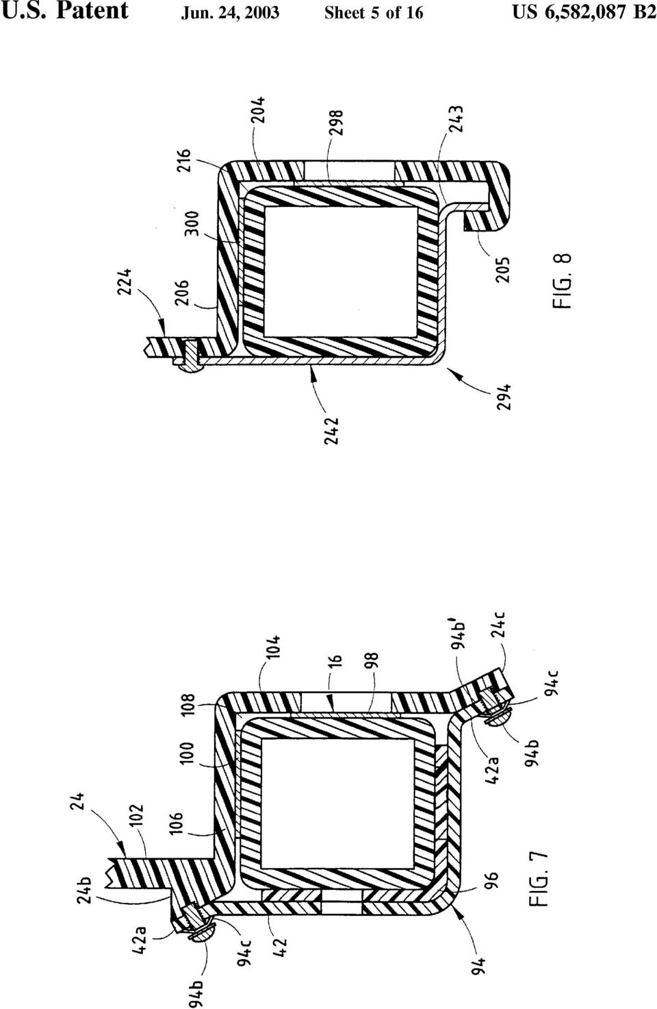
20 3 engagement With the housing. In further aspects, the load distributing member comprises an elongate member having a longitudinal extent extending along at least a portion of the support. Preferably the load distributing member comprises an arcuate-shaped elongate member. The support arm has an arcuate bearing surface and a planar side With a plurality of line bearing surfaces, With the load distributing member contacting the arcuate bearing surface and urging the line bearing surfaces to frictionally engage the housing. In further aspects, the support arm comprises a composite elongate body Which includes an elongate Webbed member having the arcuate bearing surface and a plate bearing member Which provides the line bearing surfaces. In other aspects, the housing includes a mirror casing, With the clamp urging the support into frictional engagement With the mirror casing. For example, the mirror casing may include a casing Wall Which de?nes a cavity, With the re?ective element supported in the cavity by the casing Wall. The clamp urges the support arm into frictional engagement With the casing Wall. In yet further aspects, the mirror assembly includes a positioning device, Which supports the re?ective element on the casing Wall. For example, the positioning device may comprise an electrical actuator. In another aspect, the extendable exterior rearview mirror assembly further includes a driver assembly Which selec tively moves the mirror subassembly along the support arm. According to another form of the invention, an extendable exterior rearview mirror assembly includes a mounting bracket, a mirror subassembly, and a support. The mirror subassembly includes a housing, a re?ective element, and an actuator. The housing includes a mirror casing. The support is mounted to the mounting bracket and extends from the vehicle in a laterally outward direction and into a housing of the mirror subassembly When the mirror assembly is mounted to the vehicle. The mirror assembly further includes a clamp Which mounts the mirror subassembly on the support. The clamp applies a force to the support to urge frictional engagement between the support and the mirror casing to limit movement of the mirror subassembly along the support. The mirror slides along support to one or more extended viewing positions When a force is applied to the mirror subassembly in the laterally extending direction sufficient to overcome the friction between the support and the mirror casing. In further aspects, the mirror casing includes a back Wall. The actuator preferably supports the re?ective element on the back Wall. The clamp applies a force Which urges the support into frictional engagement With the back Wall. Preferably, the clamp includes a load distributing member Which urges the support into frictional engagement With the back Wall and, further, distributes the force from the clamp along the length of the support positioned in the clamp. For example, the support preferably includes an arcuate bearing surface and a planar bearing surface. The load distribution member preferably comprises an arcuate elongate member Which engages the arcuate bearing surface of the support arm and urges the planar bearing surface of the support into frictional engagement With the exterior portion of the back Wall of the mirror casing. In yet further aspects, the arcuate elongate member form ing the load distributing member may include a plurality of inwardly projecting elongate ribs, Which contact the arcuate bearing surface of the support. In addition, the arcuate member may include a plurality of exteriorly positioned elongate ribs, Which are contacted by the clamp to mount the US 6,582,087 B mirror subassembly on the support. Preferably, the exteriorly positioned elongate ribs are offset from the inwardly pro jecting elongate ribs Which thereby form discrete spring members in the load distributing member. In other aspects, the housing further includes a cover Which is coupled to the mirror casing and de?nes a cavity into Which the support extends for frictionally engaging the mirror casing. As Will be understood, the exterior rearview mirror assembly of the present invention provides numerous advan tages over prior known extendable rearview mirror assem blies. The exterior rearview mirror assembly incorporates a single support arm for mounting the mirror subassembly to a vehicle on Which the mirror subassembly can be moved to a plurality of extended positions to provide an adjustable extended?eld of view and Which can be quickly retracted to a normal operating position Where it does not hamper the maneuverability of the vehicle or increase the Width of the vehicle. In addition, the exterior rearview mirror assembly can be adjusted either manually or by the use of a driver, Which can be operated by a remote control Within the vehicle cabin. Thus, the single arm extendable mirror assembly of the present invention provides a compact assembly With excellent vibrational performance When mounted and used on a vehicle. Hitherto, such excellent vibrational perfor mance is achieved and has been achieved commercially such as by using twin arm extendable mirror assemblies such as described in Us. Pat. No. 5,483,385 to Boddy. Achieving an acceptable and user appreciable or enjoyable exterior mirror assembly performance When the assembly is mounted to the vehicle While using a single arm is a signi?cant advantage as this allows a more compact design and thus, a more con sumer appreciable or appealing design. These and other objects, advantages, purposes and fea tures of the invention Will become more apparent from the study of the following description taken in conjunction With the drawings. BRIEF DESCRIPTION OF THE DRAWINGS FIG. 1 is a front elevation view of an extendable exterior rearview mirror assembly of the present invention; FIG. 2 is a similar view to FIG. 1 With a mirror subas sembly in an extended position; FIG. 3 is a plan view of the mirror assembly of FIG. 1 illustrating the mirror subassembly in a folded position; FIG. 4 is an exploded perspective view of the mirror assembly of FIG. 1; FIG. 5 is a partial cross-section view of the exterior rearview mirror assembly of FIG. 1 illustrating an optional driver assembly of the present invention; FIG. 6 is an exploded perspective view of a second embodiment of the support arm mounting arrangement; FIG. 7 is an enlarged partial cross-sectional view taken along line VII VII of FIG. 4; FIG. 8 is a similar view to FIG. 7 illustrating the mounting arrangement of the second embodiment of the support arm mounting arrangement of FIG. 6; FIG. 9 is a similar view to FIG. 7 illustrating a third embodiment of the mounting arrangement of the support arm of the mirror assembly; FIG. 10 is a similar view to FIG. 7 illustrating a fourth embodiment of the mounting arrangement of the support bracket of the mirror assembly; FIG. 11 is an enlarged view of the connection of the support arm assembly of FIG. 10 as viewed along line XI XI in FIG. 10;

21
22
23
24
25
26
27
28
29
US 20140196633A1 (19) United States (12) Patent Application Publication (10) Pub. N0.: US 2014/0196633 A1 Shaw (43) Pub. Date: Jul.
 United States (12) Patent Application Publication (10) Pub. N0.: US 2014/0196633 A1 Shaw (43) Pub. Date: Jul.") US 20140196633A1 (19) United States (12) Patent Application Publication (10) Pub. N0.: US 2014/0196633 A1 Shaw (43) Pub. Date: Jul. 17, 2014 (54) SECONDARY CONTAINMENT PALLET (52) US. Cl. HAVING FLEXIBLE
US 20140196633A1 (19) United States (12) Patent Application Publication (10) Pub. N0.: US 2014/0196633 A1 Shaw (43) Pub. Date: Jul. 17, 2014 (54) SECONDARY CONTAINMENT PALLET (52) US. Cl. HAVING FLEXIBLE
(12) (10) Patent N0.: US 6,740,055 B2 Dominguez (45) Date of Patent: May 25, 2004
 (10) Patent N0.: US 6,740,055 B2 Dominguez (45) Date of Patent: May 25, 2004") United States Patent US006740055B2 (12) (10) Patent N0.: US 6,740,055 B2 Dominguez (45) Date of Patent: May 25, 2004 (54) TRAUMA CERVICAL COLLAR 5,016,623 A * 5/1991 Krahenbuhl..... 602/27 5,054,475 A
United States Patent US006740055B2 (12) (10) Patent N0.: US 6,740,055 B2 Dominguez (45) Date of Patent: May 25, 2004 (54) TRAUMA CERVICAL COLLAR 5,016,623 A * 5/1991 Krahenbuhl..... 602/27 5,054,475 A
United States Patent [191 [11] Patent Number: 4,895,256
![United States Patent [191 [11] Patent Number: 4,895,256](/thumbs/29/13744178.jpg "United States Patent [191 [11] Patent Number: 4,895,256") I United States Patent [191 [11] Patent Number: 4,895,256 Johnston [45] Date of Patent: Jan. 23, 1990 [54] AIR CONDITIONING SUPPLY CARRIER 3,392,874 7/1968 3,627,122 12/1971 [76] Inventor: James E. Johnston,
I United States Patent [191 [11] Patent Number: 4,895,256 Johnston [45] Date of Patent: Jan. 23, 1990 [54] AIR CONDITIONING SUPPLY CARRIER 3,392,874 7/1968 3,627,122 12/1971 [76] Inventor: James E. Johnston,
, $55 WW 1 a 3 _g_ 3l_
 v Nov. 21, 1961 Y. c. BURNETT 3,009Q737 SEAT MOUNTED UTILITY TABLE Filed Méy 2a, 1960 / O 5 sheetisheet 1 _, dad /20?zz "Z? I IJL/BG / v40 L/ 24 I] 4//4o //2@ I 22 //Z6 W m, $55 WW 1 a 3 _g_ 3l_ 12 _/
TEPZZ 8 8 A_T EP 2 811 282 A1 (19) (11) EP 2 811 282 A1 (12) EUROPEAN PATENT APPLICATION. (51) Int Cl.: G01N 3/04 (2006.01) G01N 3/08 (2006.
 (11) EP 2 811 282 A1 (12) EUROPEAN PATENT APPLICATION. (51) Int Cl.: G01N 3/04 (2006.01) G01N 3/08 (2006.") (19) TEPZZ 8 8 A_T (11) EP 2 811 282 A1 (12) EUROPEAN PATENT APPLICATION (43) Date of publication:.12.14 Bulletin 14/0 (1) Int Cl.: G01N 3/04 (06.01) G01N 3/08 (06.01) (21) Application number: 14170412.2
(19) TEPZZ 8 8 A_T (11) EP 2 811 282 A1 (12) EUROPEAN PATENT APPLICATION (43) Date of publication:.12.14 Bulletin 14/0 (1) Int Cl.: G01N 3/04 (06.01) G01N 3/08 (06.01) (21) Application number: 14170412.2
(12) United States Patent (10) Patent N0.: US 7,068,424 B1 Jennings et al. (45) Date of Patent: Jun. 27, 2006
 United States Patent (10) Patent N0.: US 7,068,424 B1 Jennings et al. (45) Date of Patent: Jun. 27, 2006") US007068424B1 (12) United States Patent (10) Patent N0.: US 7,068,424 B1 Jennings et al. (45) Date of Patent: Jun. 27, 2006 (54) MULTIPLE PULSE GENERATION 6,141,127 A * 10/2000 Boivin et a1...... 398/92
US007068424B1 (12) United States Patent (10) Patent N0.: US 7,068,424 B1 Jennings et al. (45) Date of Patent: Jun. 27, 2006 (54) MULTIPLE PULSE GENERATION 6,141,127 A * 10/2000 Boivin et a1...... 398/92
United States Patent [19] [11] Patent Number: 5,671,124
![United States Patent [19] [11] Patent Number: 5,671,124](/thumbs/40/20728739.jpg "United States Patent [19] [11] Patent Number: 5,671,124") ' USOO5671124A United States Patent [19] [11] Patent Number: 5,671,124 H0 [45] Date of Patent: Sep. 23, 1997 [54] CIRCUIT BOARD LOCATING DEVICE 3,488,628 1/1970 Lundergan et a1...... 361/767 4,859,108
' USOO5671124A United States Patent [19] [11] Patent Number: 5,671,124 H0 [45] Date of Patent: Sep. 23, 1997 [54] CIRCUIT BOARD LOCATING DEVICE 3,488,628 1/1970 Lundergan et a1...... 361/767 4,859,108
(54) (71) (72) Vedelago (TV) (IT) (73) (21) (22) (30) Chirignago (VE) (IT); Alberto Al?er, Foreign Application Priority Data
 (71) (72) Vedelago (TV) (IT) (73) (21) (22) (30) Chirignago (VE) (IT); Alberto Al?er, Foreign Application Priority Data") US 20130094227Al (19) United States (12) Patent Application Publication (10) Pub. No.: US 2013/0094227 A1 Scordino et al. (43) Pub. Date: Apr. 18, 2013 (54) (71) (72) (73) (21) (22) (30) MOUNTING DEVICE
US 20130094227Al (19) United States (12) Patent Application Publication (10) Pub. No.: US 2013/0094227 A1 Scordino et al. (43) Pub. Date: Apr. 18, 2013 (54) (71) (72) (73) (21) (22) (30) MOUNTING DEVICE
1iillllllllllllllilllllllllllllllllllllllllllllllllillllllllllllllllllllill
 1iillllllllllllllilllllllllllllllllllllllllllllllllillllllllllllllllllllill USO05615608A Ulllt d States Patent [19] [11] Patent Number: 5,615,608 Shaw et a]. [45] Date of Patent: Apr. 1, 1997 [54] REINFORCED
A LIGHTWEIGHT REAR BUMPER WITH CRASH WORTHY COMPARTMENT
 1 A LIGHTWEIGHT REAR BUMPER WITH CRASH WORTHY COMPARTMENT Background of the Invention Field of the Invention This invention relates to a lightweight rear bumper with crash worthy compartment, and more
United States Patent [191 Romo et al.
 United States Patent [191 Romo et al. [54] APPARATUS FOR PREVENTING NECK INJURY [76] Inventors: Leon E. Romo, Box 1 A Rt. 5, Annapolis, Md. 211; Jack T. Andrish, 120 E. 216 St., Euclid, Ohio 44123 [22]
(54) (71) (72) (21) (22) (51) (52)
 (71) (72) (21) (22) (51) (52)") US 20140173950A1 (19) United States (12) Patent Application Publication (10) Pub. No.: US 2014/0173950 A1 Neri (43) Pub. Date: Jun. 26, 2014 (54) (71) (72) (21) (22) (51) (52) MEDAL-MOUNTING ASSEMBLY Applicant:
US 20140173950A1 (19) United States (12) Patent Application Publication (10) Pub. No.: US 2014/0173950 A1 Neri (43) Pub. Date: Jun. 26, 2014 (54) (71) (72) (21) (22) (51) (52) MEDAL-MOUNTING ASSEMBLY Applicant:
NOV. 21, 1967 P J, FELLNER, JR 3,353,652 FEEDING AND INDEXING DEVICE FOR PACKAGE HANDLING APPARATUS. Filed May 25, 1967 2 Sheets-Sheet 1 /, 27
 NOV. 21, 1967 P J, FELLNER, JR FEEDING AND INDEXING DEVICE FOR PACKAGE HANDLING APPARATUS Filed May 25, 1967 2 Sheets-Sheet 1..Z., 76 60 A5 27 Q2 29 /, 27 a0 /@ /5 70 74 4 /9.32 5.77% ATTO 2N EY v Nov.
US 20060209260A1 (19) United States (12) Patent Application Publication (10) Pub. No.: US 2006/0209260 A1 Clegg (43) Pub. Date: Sep.
 United States (12) Patent Application Publication (10) Pub. No.: US 2006/0209260 A1 Clegg (43) Pub. Date: Sep.") US 20060209260A1 (19) United States (12) Patent Application Publication (10) Pub. No.: Clegg (43) Pub. Date: Sep. 21, 2006 (54) SCROLLING PICTURE CHANGER (52) US. Cl...... 352/98 (76) Inventor: Timothy
US 20060209260A1 (19) United States (12) Patent Application Publication (10) Pub. No.: Clegg (43) Pub. Date: Sep. 21, 2006 (54) SCROLLING PICTURE CHANGER (52) US. Cl...... 352/98 (76) Inventor: Timothy
(12) United States Patent Fritsche et al.
 United States Patent Fritsche et al.") (12) United States Patent Fritsche et al. US006659159B2 (10) Patent N0.: (45) Date of Patent: US 6,659,159 B2 Dec. 9, 2003 (54) (75) (73) ( * ) (21) (22) (65) (51) (52) (58) (56) SCREEN MOUNTING APPARATUS
(12) United States Patent Fritsche et al. US006659159B2 (10) Patent N0.: (45) Date of Patent: US 6,659,159 B2 Dec. 9, 2003 (54) (75) (73) ( * ) (21) (22) (65) (51) (52) (58) (56) SCREEN MOUNTING APPARATUS
(72) Inventors: Juergen RIEDL, Koenigsbrunn (DE); USPC ( 267/285)
 Inventors: Juergen RIEDL, Koenigsbrunn (DE); USPC ( 267/285)") US 20130087957A1 (19) United States (12) Patent Application Publication (10) Pub. No.: US 2013/0087957 A1 RIEDL et al. (43) Pub. Date: Apr. 11, 2013 (54) DEVICE FOR DAMPING THE VIBRATIONS Publication Classi?cation
US 20130087957A1 (19) United States (12) Patent Application Publication (10) Pub. No.: US 2013/0087957 A1 RIEDL et al. (43) Pub. Date: Apr. 11, 2013 (54) DEVICE FOR DAMPING THE VIBRATIONS Publication Classi?cation
US 20130073440A1 (19) United States (12) Patent Application Publication (10) Pub. No.: US 2013/0073440 A1 Chen (57)
 United States (12) Patent Application Publication (10) Pub. No.: US 2013/0073440 A1 Chen (57)") US 20130073440A1 (19) United States (12) Patent Application Publication (10) Pub. No.: US 2013/0073440 A1 Chen (43) Pub. Date: Mar. 21, 2013 (54) PAYROLL SYSTEM AND METHOD Publication Classi?cation (76)
US 20130073440A1 (19) United States (12) Patent Application Publication (10) Pub. No.: US 2013/0073440 A1 Chen (43) Pub. Date: Mar. 21, 2013 (54) PAYROLL SYSTEM AND METHOD Publication Classi?cation (76)
\ \ \ connection connection connection interface interface interface
 US 20140122910A1 (19) United States (12) Patent Application Publication (10) Pub. No.: US 20140122910 A1 Chiu et al. (43) Pub. Date: May 1, 2014 (54) RACK SERVER SYSTEM AND OPERATION Publication Classi?cation
Oct. 31, 1939. ' E_ Ross 2,177,788 FILM MARKING DEVI CE ATTORNEY
 Oct. 31, 1939. ' E_ Ross 2,177,788 FILM MARKING DEVI CE Filed Sept. 14, 1934 3 Sheets-Sheet l ATTORNEY Oct. 313, 1939, l- E, Ross 2,177,788 FILM MARKING DEVICE Filed Sept. 14, 1934 3 Sheets-Sheet 2 \\
I4 '2 ORLANDO J. CHIAPPE Y.
 '. ' Dec. 6, 1960 o. J. GHIAPPE 2,963,058 DIE FOR BELLOWS 0R CORRUGA'l- ING MACHINE Filed Jan. 20, 1958 5 Sheets-Sheet 1 ' INVENTOR. I4 '2 ORLANDO J. CHIAPPE Y. - ATTORNEY _ Dec. 6, 1960 o. J. CHIAPPE
(12) Ulllted States Patent (10) Patent N0.: US 8,389,837 B1 Leguia (45) Date of Patent: Mar. 5, 2013
 Ulllted States Patent (10) Patent N0.: US 8,389,837 B1 Leguia (45) Date of Patent: Mar. 5, 2013") US008389837B1 (12) Ulllted States Patent (10) Patent N0.: US 8,389,837 B1 Leguia (45) Date of Patent: Mar. 5, 2013 (54) STRINGED INSTRUMENT HAVINGA 4,836,076 A 6/1989 Bernier FRETBOARD CANTILEVERED OVER
US008389837B1 (12) Ulllted States Patent (10) Patent N0.: US 8,389,837 B1 Leguia (45) Date of Patent: Mar. 5, 2013 (54) STRINGED INSTRUMENT HAVINGA 4,836,076 A 6/1989 Bernier FRETBOARD CANTILEVERED OVER
Canady (43) Pub. Date: Feb. 16, 2006
 Pub. Date: Feb. 16, 2006") US 20060036239A1 (19) United States (12) Patent Application Publication (10) Pub. N0.: US 2006/0036239 A1 Canady (43) Pub. Date: Feb. 16, 2006 (54) COMBINATION ARGON PLASMA COAGULATION AND ELECTROCAUTERY
US 20060036239A1 (19) United States (12) Patent Application Publication (10) Pub. N0.: US 2006/0036239 A1 Canady (43) Pub. Date: Feb. 16, 2006 (54) COMBINATION ARGON PLASMA COAGULATION AND ELECTROCAUTERY
(12) United States Patent (10) Patent No.: US 8,253,226 B2 Oguri (45) Date of Patent: Aug. 28, 2012
 United States Patent (10) Patent No.: US 8,253,226 B2 Oguri (45) Date of Patent: Aug. 28, 2012") US008253226B2 (12) United States Patent (10) Patent No.: US 8,253,226 B2 Oguri (45) Date of Patent: Aug. 28, 2012 (54) ELECTRONIC PARTS, AND METHOD FOR (56) References Cited ARRANGING SHIELDING CASE AND
US008253226B2 (12) United States Patent (10) Patent No.: US 8,253,226 B2 Oguri (45) Date of Patent: Aug. 28, 2012 (54) ELECTRONIC PARTS, AND METHOD FOR (56) References Cited ARRANGING SHIELDING CASE AND
(12) United States Patent (16) Patent N6.= US 6,198,814 B1 Gill (45) Date of Patent: Mar. 6, 2001
 United States Patent (16) Patent N6.= US 6,198,814 B1 Gill (45) Date of Patent: Mar. 6, 2001") US006198814B1 (12) United States Patent (16) Patent N6.= Gill (45) Date of Patent: Mar. 6, 2001 (54) SYSTEM AND METHOD FOR ENTERING 5,621,790 * 4/1997 Grossman 6161...... 379/266 CALL OUTCOME RECORDS IN
US006198814B1 (12) United States Patent (16) Patent N6.= Gill (45) Date of Patent: Mar. 6, 2001 (54) SYSTEM AND METHOD FOR ENTERING 5,621,790 * 4/1997 Grossman 6161...... 379/266 CALL OUTCOME RECORDS IN
. tlllll,1! 1% 11:11 I.,W/ "-111 // out AIHI/ ) I \\ M10. 1 I! (1' 1L- 1!!! I VEHICLE} I] r20 (TRAFFIC COMPUTER 10 RECEIVING UNIT 41 I \ ")SENSOR
![. tlllll,1! 1% 11:11 I.,W/ -111 // out AIHI/ ) I \\ M10. 1 I! (1' 1L- 1!!! I VEHICLE} I] r20 (TRAFFIC COMPUTER 10 RECEIVING UNIT 41 I \ )SENSOR](/thumbs/32/15591097.jpg ". tlllll,1! 1% 11:11 I.,W/ -111 // out AIHI/ ) I \\ M10. 1 I! (1' 1L- 1!!! I VEHICLE} I] r20 (TRAFFIC COMPUTER 10 RECEIVING UNIT 41 I \ )SENSOR") United States Patent [19] Albrecht et al. US005812069A [11] Patent Number: [] Date of Patent: Sep. 22, 1998 [54] METHOD AND SYSTEM FOR FORECASTING TRAFFIC FLOWS [75] Inventors: UWe Albrecht, Miinchen;
United States Patent [19] Albrecht et al. US005812069A [11] Patent Number: [] Date of Patent: Sep. 22, 1998 [54] METHOD AND SYSTEM FOR FORECASTING TRAFFIC FLOWS [75] Inventors: UWe Albrecht, Miinchen;
int. CI e: E05B 65/00, E05B 15/00
 J Europaisches Patentamt European Patent Office Office europeen des brevets Publication number: 0 672 808 A1 EUROPEAN PATENT APPLICATION Application number: 95200564.3 int. CI e: E05B 65/00, E05B 15/00
USOO5469362A United States Patent [191 [11] Patent Number: 5,469,362. Hunt et al. [45] Date of Patent: Nov. 21, 1995
![USOO5469362A United States Patent [191 [11] Patent Number: 5,469,362. Hunt et al. [45] Date of Patent: Nov. 21, 1995](/thumbs/30/14713887.jpg "USOO5469362A United States Patent [191 [11] Patent Number: 5,469,362. Hunt et al. [45] Date of Patent: Nov. 21, 1995") llllllllllllllllllllllllllllllllllllllllll l llllllllllllllllllllllll USOO5469362A United States Patent [191 [11] Patent Number: 5,469,362 Hunt et al. [45] Date of Patent: Nov. 21, 1995 [54] DISPATCHING
llllllllllllllllllllllllllllllllllllllllll l llllllllllllllllllllllll USOO5469362A United States Patent [191 [11] Patent Number: 5,469,362 Hunt et al. [45] Date of Patent: Nov. 21, 1995 [54] DISPATCHING
*EP001520563A1* EP 1 520 563 A1 (19) (11) EP 1 520 563 A1 (12) EUROPEAN PATENT APPLICATION. (43) Date of publication: 06.04.2005 Bulletin 2005/14
 (11) EP 1 520 563 A1 (12) EUROPEAN PATENT APPLICATION. (43) Date of publication: 06.04.2005 Bulletin 2005/14") (19) Europäisches Patentamt European Patent Office Office européen des brevets *EP001520563A1* (11) EP 1 520 563 A1 (12) EUROPEAN PATENT APPLICATION (43) Date of publication: 06.04.2005 Bulletin 2005/14
(19) Europäisches Patentamt European Patent Office Office européen des brevets *EP001520563A1* (11) EP 1 520 563 A1 (12) EUROPEAN PATENT APPLICATION (43) Date of publication: 06.04.2005 Bulletin 2005/14
Hay (43) Pub. Date: Oct. 17, 2002
 Pub. Date: Oct. 17, 2002") US 20020152322A1 (19) United States (12) Patent Application Publication (10) Pub. No.: US 2002/0152322 A1 Hay (43) Pub. Date: Oct. 17, 2002 (54) (76) (21) (22) (51) (52) METHOD AND APPARATUS FOR FACILITATING
US 20020152322A1 (19) United States (12) Patent Application Publication (10) Pub. No.: US 2002/0152322 A1 Hay (43) Pub. Date: Oct. 17, 2002 (54) (76) (21) (22) (51) (52) METHOD AND APPARATUS FOR FACILITATING
(71) Applicant: SPEAKWRITE, LLC,Austin, TX (US)
 Applicant: SPEAKWRITE, LLC,Austin, TX (US)") US 20130304465Al (19) United States (12) Patent Application Publication (10) Pub. No.: US 2013/0304465 A1 Henry et al. (43) Pub. Date: NOV. 14, 2013 (54) METHOD AND SYSTEM FOR AUDIO-VIDEO (52) US. Cl.
US 20130304465Al (19) United States (12) Patent Application Publication (10) Pub. No.: US 2013/0304465 A1 Henry et al. (43) Pub. Date: NOV. 14, 2013 (54) METHOD AND SYSTEM FOR AUDIO-VIDEO (52) US. Cl.
(Us) (73) Assignee: Avaya Technology Corp. Je?' McElroy, Columbia, SC (US); (21) Appl. No.: 10/413,024. (22) Filed: Apr. 14, 2003 (57) ABSTRACT
 (73) Assignee: Avaya Technology Corp. Je?' McElroy, Columbia, SC (US); (21) Appl. No.: 10/413,024. (22) Filed: Apr. 14, 2003 (57) ABSTRACT") US 20040202300A1 (19) United States (12) Patent Application Publication (10) Pub. No.: US 2004/0202300 A1 Cooper et al. (43) Pub. Date: Oct. 14, 2004 (54) CALL HANDLING USING NON-SPEECH CUES VIA A PERSONAL
US 20040202300A1 (19) United States (12) Patent Application Publication (10) Pub. No.: US 2004/0202300 A1 Cooper et al. (43) Pub. Date: Oct. 14, 2004 (54) CALL HANDLING USING NON-SPEECH CUES VIA A PERSONAL
US 20090157756Al (19) United States (12) Patent Application Publication (10) Pub. No.: US 2009/0157756 A1 Sanvido (43) Pub. Date: Jun.
 United States (12) Patent Application Publication (10) Pub. No.: US 2009/0157756 A1 Sanvido (43) Pub. Date: Jun.") US 20090157756Al (19) United States (12) Patent Application Publication (10) Pub. No.: US 2009/0157756 A1 Sanvido (43) Pub. Date: Jun. 18, 2009 (54) FILE SYSTEM FOR STORING FILES IN Publication Classi?cation
US 20090157756Al (19) United States (12) Patent Application Publication (10) Pub. No.: US 2009/0157756 A1 Sanvido (43) Pub. Date: Jun. 18, 2009 (54) FILE SYSTEM FOR STORING FILES IN Publication Classi?cation
H. G. SHORTT. VACUUM -AGTUATED SCREEN. MPL'IOATION FILED 13.80.19, 1907. 4 SHEETS-SHEET 1.
 No. 896,473. - PATBNTED AUG. 18,1908. ` H. G. SHORTT. VACUUM -AGTUATED SCREEN. MPL'IOATION FILED 13.80.19, 1907. 4 SHEETS-SHEET 1. No. 896,473. PATENTED AUG. 18, 1908.VA` > H. G. 'SH0RTT~ VACUUM AGTUATBD
(43) Pub. Date: Feb. 16, 2012
 Pub. Date: Feb. 16, 2012") US 20120041897A1 (19) United States (12) Patent Application Publication (10) Pub. No.: US 2012/0041897 A1 Teague et al. (43) Pub. Date: (54) (75) (73) (21) (22) (63) MARKET INDICATOR PROCESS AND METHOD
US 20120041897A1 (19) United States (12) Patent Application Publication (10) Pub. No.: US 2012/0041897 A1 Teague et al. (43) Pub. Date: (54) (75) (73) (21) (22) (63) MARKET INDICATOR PROCESS AND METHOD
Ulllted States Patent [19] [11] Patent Number: 6,029,830
![Ulllted States Patent [19] [11] Patent Number: 6,029,830](/thumbs/40/20861563.jpg "Ulllted States Patent [19] [11] Patent Number: 6,029,830") US006029830A Ulllted States Patent [19] [11] Patent Number: 6,029,830 Manookian [45] Date of Patent: Feb. 29, 2000 [54] SPORTS EQUIPMENT HANGING BELT 4,049,126 9/1977 Halverson..... 211/8701 4,052,805
US006029830A Ulllted States Patent [19] [11] Patent Number: 6,029,830 Manookian [45] Date of Patent: Feb. 29, 2000 [54] SPORTS EQUIPMENT HANGING BELT 4,049,126 9/1977 Halverson..... 211/8701 4,052,805
US 201 10264472Al (19) United States (12) Patent Application Publication (10) Pub. N0.: US 201 1/0264472 A1 Mostelac (43) Pub. Date: Oct.
 United States (12) Patent Application Publication (10) Pub. N0.: US 201 1/0264472 A1 Mostelac (43) Pub. Date: Oct.") US 201 10264472Al (19) United States (12) Patent Application Publication (10) Pub. N0.: US 201 1/0264472 A1 Mostelac (43) Pub. Date: Oct. 27, 201 1 (54) DEDUCTIBLE SHIELD (57) ABSTRACT (75) Inventor: Felix
US 201 10264472Al (19) United States (12) Patent Application Publication (10) Pub. N0.: US 201 1/0264472 A1 Mostelac (43) Pub. Date: Oct. 27, 201 1 (54) DEDUCTIBLE SHIELD (57) ABSTRACT (75) Inventor: Felix
US 20100054637Al (19) United States (12) Patent Application Publication (10) Pub. N0.: US 2010/0054637 A1 TIRPAN (43) Pub. Date: Mar.
 United States (12) Patent Application Publication (10) Pub. N0.: US 2010/0054637 A1 TIRPAN (43) Pub. Date: Mar.") US 20100054637Al (19) United States (12) Patent Application Publication (10) Pub. N0.: US 2010/0054637 A1 TIRPAN (43) Pub. Date: Mar. 4, 2010 (54) ENCLOSURE FOR ITEMS SUSCEPTIBLE TO (52) US. Cl...... 383/64
US 20100054637Al (19) United States (12) Patent Application Publication (10) Pub. N0.: US 2010/0054637 A1 TIRPAN (43) Pub. Date: Mar. 4, 2010 (54) ENCLOSURE FOR ITEMS SUSCEPTIBLE TO (52) US. Cl...... 383/64
(12) United States Patent
 United States Patent") (12) United States Patent US006934727B2 (10) Patent N0.: US 6,934,727 B2 Berkowitz et al. (45) Date of Patent: *Aug. 23, 2005 (54) DYNAMIC SYNCHRONIZATION OF TABLES 6,052,695 A * 4/2000 Abe et a1......
(12) United States Patent US006934727B2 (10) Patent N0.: US 6,934,727 B2 Berkowitz et al. (45) Date of Patent: *Aug. 23, 2005 (54) DYNAMIC SYNCHRONIZATION OF TABLES 6,052,695 A * 4/2000 Abe et a1......
(12) United States Patent (10) Patent N0.: US 8,721,047 B2 Sakurai et a]. (45) Date of Patent: May 13, 2014
![(12) United States Patent (10) Patent N0.: US 8,721,047 B2 Sakurai et a]. (45) Date of Patent: May 13, 2014](/thumbs/39/20155291.jpg "(12) United States Patent (10) Patent N0.: US 8,721,047 B2 Sakurai et a]. (45) Date of Patent: May 13, 2014") USOO8721047B2 (12) United States Patent (10) Patent N0.: US 8,721,047 B2 Sakurai et a]. (45) Date of Patent: May 13, 2014 (54) LIQUID EJECTION HEAD AND INK JET (56) References Cited PRINTING APPARATUS
USOO8721047B2 (12) United States Patent (10) Patent N0.: US 8,721,047 B2 Sakurai et a]. (45) Date of Patent: May 13, 2014 (54) LIQUID EJECTION HEAD AND INK JET (56) References Cited PRINTING APPARATUS
Recreational Vehicle Towing Guide
 Recreational Vehicle Towing Guide TABLE OF CONTENTS HOW TO DETERMINE THE GROSS VEHICLE WEIGHT RATING FOR RECREATIONAL VEHICLES Terms and Definitions... 2 Conversion... 3 Net Weight... 4 Manufacturer Gross
(12) United States Patent (10) Patent No.: US 8,512,370 B2 Sorensen (45) Date of Patent: Aug. 20, 2013
 United States Patent (10) Patent No.: US 8,512,370 B2 Sorensen (45) Date of Patent: Aug. 20, 2013") US008512370B2 (12) United States Patent (10) Patent No.: US 8,512,370 B2 Sorensen (45) Date of Patent: Aug. 20, 2013 (54) PILLOW WITH PLURALITY OF BALLS FOR (56) References Cited RELIEVING SINUS AND CONGESTION
US008512370B2 (12) United States Patent (10) Patent No.: US 8,512,370 B2 Sorensen (45) Date of Patent: Aug. 20, 2013 (54) PILLOW WITH PLURALITY OF BALLS FOR (56) References Cited RELIEVING SINUS AND CONGESTION
March 2, 1971. J. A. GENTILuoMo 3,567,223 GOLF RANGE BALL HANDLING MEANS. Filed Jan. 20. 1967. 2 Sheets-Sheet 1. BY Mdm
 March 2, 1971 Filed Jan.. 1967 J. A. GENTILuoMo GOLF RANGE BALL HANDLING MEANS 2 Sheets-Sheet 1 BY Mdm l March 2,-11971 J. A. GENTlLuoMo ~ l l GOLF RANGE BALL HANDLING MEANS Filed Jan. 2o, 1967 ' 2 sheets-sheet
Ulllted States Patent [19] [11] Patent Number: 5,992,923. Wycech [45] Date 0f Patent: Nov. 30, 1999
![Ulllted States Patent [19] [11] Patent Number: 5,992,923. Wycech [45] Date 0f Patent: Nov. 30, 1999](/thumbs/40/20828367.jpg "Ulllted States Patent [19] [11] Patent Number: 5,992,923. Wycech [45] Date 0f Patent: Nov. 30, 1999") US005992923A Ulllted States Patent [19] [11] Patent Number: 5,992,923 Wycech [45] Date 0f Patent: Nov. 30, 1999 [54] REINFORCED BEAM ASSEMBLY 4,923,902 5/1990 Wycech. 4,978,562 12/1990 Wycech. [75] Inventor:
US005992923A Ulllted States Patent [19] [11] Patent Number: 5,992,923 Wycech [45] Date 0f Patent: Nov. 30, 1999 [54] REINFORCED BEAM ASSEMBLY 4,923,902 5/1990 Wycech. 4,978,562 12/1990 Wycech. [75] Inventor:
US 20020072350A1 (19) United States (12) Patent Application Publication (10) Pub. No.: US 2002/0072350 A1 Fukuzato (43) Pub. Date: Jun.
 United States (12) Patent Application Publication (10) Pub. No.: US 2002/0072350 A1 Fukuzato (43) Pub. Date: Jun.") US 20020072350A1 (19) United States (12) Patent Application Publication (10) Pub. No.: US 20020072350 A1 Fukuzato (43) Pub. Date: Jun. 13, 2002 (54) BACKUP METHOD OF APPLICATIONS OF PORTABLE CELLULAR PHONE
US 20020072350A1 (19) United States (12) Patent Application Publication (10) Pub. No.: US 20020072350 A1 Fukuzato (43) Pub. Date: Jun. 13, 2002 (54) BACKUP METHOD OF APPLICATIONS OF PORTABLE CELLULAR PHONE
3,213,816. Oct. 26, 1965 42/ V//////////A 22 "71% / ' ///////1 J. SOLANKA. Filed Feb. 25, 1963 2 Sheets-Sheet 1. 34 32 2s 34 3o, 46 48 4o ATTORNEY
 Oct. 26, 1965 J. SOLANKA METHOD AND MEANS FOR SEWING AND SHANKING BUTTONS Filed Feb. 25, 1963 2 Sheets-Sheet 1 J 34 32 2s 34 3o, 46 48 4o Q? V//////////A 22 llhd. I. Val 24 28 _ 42/ "71% / ' ///////1 5o
Feb. 21, 1967. o. J. B. ORWIN ETAL 3,305,058. Filed March 2, 1965 2 Sheets-Sheet 1' OVER-LOAD CLUTCH. DAVID Tenn FORTuNé
 Feb. 21, 1967 o. J. B. ORWIN ETAL Filed March 2, 1965 2 Sheets-Sheet 1' DAVID Tenn FORTuNé ' Feb. 21, 1967 o. J. B. ORWIN ETAL. Filed March 2, 1965 2 Sheets-Sheet,2 H57. 4 IN VENT'ORS. OLAF :mw 60mm»!
US 20020141557A1 (19) United States (12) Patent Application Publication (10) Pub. No.: US 2002/0141557 A1 STRANDBERG (43) Pub. Date: Oct.
 United States (12) Patent Application Publication (10) Pub. No.: US 2002/0141557 A1 STRANDBERG (43) Pub. Date: Oct.") ---- US 20020141557A1 (19) United States (12) Patent Application Publication (10) Pub. No.: US 2002/0141557 A1 STRANDBERG (43) Pub. Date: (54) SYSTEM AND METHOD FOR PROVIDING AN AUTOMATIC TELEPHONE CALL
---- US 20020141557A1 (19) United States (12) Patent Application Publication (10) Pub. No.: US 2002/0141557 A1 STRANDBERG (43) Pub. Date: (54) SYSTEM AND METHOD FOR PROVIDING AN AUTOMATIC TELEPHONE CALL
(12) United States Patent (10) Patent N0.: US 8,282,471 B1 Korner (45) Date of Patent: Oct. 9, 2012
 United States Patent (10) Patent N0.: US 8,282,471 B1 Korner (45) Date of Patent: Oct. 9, 2012") US008282471B1 (12) United States Patent (10) Patent N0.: US 8,282,471 B1 Korner (45) Date of Patent: Oct. 9, 2012 (54) COMPUTER-IMPLEMENTED SPORTS 2011/0003634 A1* 1/2011 Manteris..... 463/25 WAGERING
US008282471B1 (12) United States Patent (10) Patent N0.: US 8,282,471 B1 Korner (45) Date of Patent: Oct. 9, 2012 (54) COMPUTER-IMPLEMENTED SPORTS 2011/0003634 A1* 1/2011 Manteris..... 463/25 WAGERING
llllllllllllllillllllllllllllllllllllllllllllllllllllllllllllllllllllllllll
 llllllllllllllillllllllllllllllllllllllllllllllllllllllllllllllllllllllllll USOO5535162A United States Patent [19] [11] Patent Number: 5,535,162 Uenoyama [45] Date of Patent: Jul. 9, 1996 [54] ELECTRICALLY
US 20070028343A1 (19) United States (12) Patent Application Publication (10) Pub. N0.: US 2007/0028343 A1 Makowka (43) Pub. Date: Feb.
 United States (12) Patent Application Publication (10) Pub. N0.: US 2007/0028343 A1 Makowka (43) Pub. Date: Feb.") US 20070028343A1 (19) United States (12) Patent Application Publication (10) Pub. N0.: US 2007/0028343 A1 Makowka (43) Pub. Date: Feb. 8, 2007 (54) DISPOSABLE PROTECTIVE GARMENT Publication Classi?cation
US 20070028343A1 (19) United States (12) Patent Application Publication (10) Pub. N0.: US 2007/0028343 A1 Makowka (43) Pub. Date: Feb. 8, 2007 (54) DISPOSABLE PROTECTIVE GARMENT Publication Classi?cation
United States Patent [19] [11] Patent Number: 4,893,344
![United States Patent [19] [11] Patent Number: 4,893,344](/thumbs/40/21012473.jpg "United States Patent [19] [11] Patent Number: 4,893,344") United States Patent [19] [11] Patent Number: 4,893,344 Triigardh et a1. [45] Date of Patent: Jan. 9, 1990 [54] HEADSET HAVING A POST AURICLE 4,335,281 l/ 1982 Scott et a1...... 379/430 MOUNT AND ARRANGED
United States Patent [19] [11] Patent Number: 4,893,344 Triigardh et a1. [45] Date of Patent: Jan. 9, 1990 [54] HEADSET HAVING A POST AURICLE 4,335,281 l/ 1982 Scott et a1...... 379/430 MOUNT AND ARRANGED
5' i > 95 l 4. United States Patent Barnett [151 3,699,515. 1451 Oct. 17, 1972. (opr/oa/al) '0. [22] Filed: Jan. 4, 19,71 [21] Appl. No.
![5' i > 95 l 4. United States Patent Barnett [151 3,699,515. 1451 Oct. 17, 1972. (opr/oa/al) '0. [22] Filed: Jan. 4, 19,71 [21] Appl. No.](/thumbs/19/343585.jpg "5' i > 95 l 4. United States Patent Barnett [151 3,699,515. 1451 Oct. 17, 1972. (opr/oa/al) '0. [22] Filed: Jan. 4, 19,71 [21] Appl. No.") United States Patent Barnett [541 MOVEMENT RESPONSIVE ALARM SYSTEM FOR A VEHICLE [72] Inventor: Howard James Barnett, 4433 North Stanton, Apt. 412, El Paso, Tex. 79920 [22] Filed: Jan. 4, 19,71 [21] Appl.
United States Patent Barnett [541 MOVEMENT RESPONSIVE ALARM SYSTEM FOR A VEHICLE [72] Inventor: Howard James Barnett, 4433 North Stanton, Apt. 412, El Paso, Tex. 79920 [22] Filed: Jan. 4, 19,71 [21] Appl.
IN00419 (rev A) Aqua 6 Glide Quadrant and Off-set Quadrant Enclosure
 Aqua 6 Glide Quadrant and Off-set Quadrant Enclosure") IN00419 (rev A) Aqua 6 Glide Quadrant and Off-set Quadrant Enclosure Instruction suitable for both Quadrant & Off-set Quadrant variations. Instruction suitable for both Right and Left Hand fixing variations
IN00419 (rev A) Aqua 6 Glide Quadrant and Off-set Quadrant Enclosure Instruction suitable for both Quadrant & Off-set Quadrant variations. Instruction suitable for both Right and Left Hand fixing variations
(12) Unlted States Patent (10) Patent N0.2 US 7,428,664 B2 Sirbu (45) Date of Patent: Sep. 23, 2008
 Unlted States Patent (10) Patent N0.2 US 7,428,664 B2 Sirbu (45) Date of Patent: Sep. 23, 2008") US007428664B2 (12) Unlted States Patent (10) Patent N0.2 Sirbu (45) Date of Patent: Sep. 23, 2008 (54) PROTOCOL REPLAY SYSTEM 5,287,506 A * 2/1994 Whiteside..... 714/39 6,708,292 B1 * 3/2004 Mangasarian..
US007428664B2 (12) Unlted States Patent (10) Patent N0.2 Sirbu (45) Date of Patent: Sep. 23, 2008 (54) PROTOCOL REPLAY SYSTEM 5,287,506 A * 2/1994 Whiteside..... 714/39 6,708,292 B1 * 3/2004 Mangasarian..
US 20070139188A1 (19) United States (12) Patent Application Publication (10) Pub. No.: US 2007/0139188 A1 Ollis et al. HOME PROCESSOR /\ J\ NETWORK
 United States (12) Patent Application Publication (10) Pub. No.: US 2007/0139188 A1 Ollis et al. HOME PROCESSOR /\ J\ NETWORK") US 20070139188A1 (19) United States (12) Patent Application Publication (10) Pub. No.: US 2007/0139188 A1 Ollis et al. (43) Pub. Date: Jun. 21, 2007 (54) (75) (73) (21) (22) METHOD AND APPARATUS FOR COMMUNICATING
US 20070139188A1 (19) United States (12) Patent Application Publication (10) Pub. No.: US 2007/0139188 A1 Ollis et al. (43) Pub. Date: Jun. 21, 2007 (54) (75) (73) (21) (22) METHOD AND APPARATUS FOR COMMUNICATING
Dec- 2, 1969 M. v. 8. BROWN ET AL 3,482,037
 Dec- 2, 1969 M. v. 8. BROWN ET AL 3,482,037 HOME SECURITY SYSTEM UTILIZING TELEVISION SURVEILLANCE Filed Aug. 1, 1966 3 Sheets-Sheet 1 VIDEO scaumsn / r55 / I a J Dec. 2, 1969 M. v. B. BROWI-Q ETAL '
Story (43) Pub. Date: Apr. 26, 2001
 Pub. Date: Apr. 26, 2001") US 20010000486A1 (19) United States (12) Patent Application Publication (10) Pub. No.: US 2001/0000486 A1 Story (43) Pub. Date: Apr. 26, 2001 (54) DENTAL IMPLANT HAVING A FORCE Related US. Application
US 20010000486A1 (19) United States (12) Patent Application Publication (10) Pub. No.: US 2001/0000486 A1 Story (43) Pub. Date: Apr. 26, 2001 (54) DENTAL IMPLANT HAVING A FORCE Related US. Application
llllllllllllll lllllllllll?glliugwilllllllllllllllllllllllllllllllll
 llllllllllllll lllllllllll?glliugwilllllllllllllllllllllllllllllllll United States Patent [19] [11] Patent Number: 5,497,091 Bratton et al. [45] Date of Patent: Mar. 5, 1996 [54] SURFACE MOUNTED PH SENSOR
The hydraulically damped overrun control device is made up of six main elements that control and operate the braking system.
 THE OVERRUN PRINCIPLE The hydraulically damped overrun control device is made up of six main elements that control and operate the braking system. 1. The Housing 2. The Drawtube 3. The Overrun Lever of
Understanding patent claims (d) Double pipe
 Double pipe") Understanding patent claims (d) Double pipe The invention The invention relates to a double pipe and a method of manufacturing it. The double pipe is preferably employed in a vehicle air conditioner for
Understanding patent claims (d) Double pipe The invention The invention relates to a double pipe and a method of manufacturing it. The double pipe is preferably employed in a vehicle air conditioner for
TEPZZ 9 _88_A_T EP 2 921 881 A1 (19) (11) EP 2 921 881 A1 (12) EUROPEAN PATENT APPLICATION
 (11) EP 2 921 881 A1 (12) EUROPEAN PATENT APPLICATION") (19) TEPZZ 9 _88_A_T (11) EP 2 921 881 A1 (12) EUROPEAN PATENT APPLICATION (43) Date of publication: 23.09.1 Bulletin 1/39 (21) Application number: 1416041.2 (1) Int Cl.: G01T 1/ (06.01) G03B 42/02 (06.01)
(19) TEPZZ 9 _88_A_T (11) EP 2 921 881 A1 (12) EUROPEAN PATENT APPLICATION (43) Date of publication: 23.09.1 Bulletin 1/39 (21) Application number: 1416041.2 (1) Int Cl.: G01T 1/ (06.01) G03B 42/02 (06.01)
(12) (10) Patent N0.: US 6,289,315 B1 Calvi (45) Date of Patent: Sep. 11, 2001
 (10) Patent N0.: US 6,289,315 B1 Calvi (45) Date of Patent: Sep. 11, 2001") United States Patent US006289315B1 (12) (10) Patent N0.: US 6,289,315 B1 Calvi (45) Date of Patent: Sep. 11, 2001 (54) CREDIT CARD SWIPE SYSTEM 5,828,044 * 10/1998 Jun et a1...... 235/380 5,828,738 * 10/1998
United States Patent US006289315B1 (12) (10) Patent N0.: US 6,289,315 B1 Calvi (45) Date of Patent: Sep. 11, 2001 (54) CREDIT CARD SWIPE SYSTEM 5,828,044 * 10/1998 Jun et a1...... 235/380 5,828,738 * 10/1998
US 20130169877A1 (19) United States (12) Patent Application Publication (10) Pub. N0.: US 2013/0169877 A1 DANG (43) Pub. Date: Jul.
 United States (12) Patent Application Publication (10) Pub. N0.: US 2013/0169877 A1 DANG (43) Pub. Date: Jul.") US 20130169877A1 (19) United States (12) Patent Application Publication (10) Pub. N0.: US 2013/0169877 A1 DANG (43) Pub. Date: Jul. 4, 2013 (54) SUPPLEMENTAL AUDIO AND VISUAL (52) US. Cl. SYSTEM FORA VIDEO
US 20130169877A1 (19) United States (12) Patent Application Publication (10) Pub. N0.: US 2013/0169877 A1 DANG (43) Pub. Date: Jul. 4, 2013 (54) SUPPLEMENTAL AUDIO AND VISUAL (52) US. Cl. SYSTEM FORA VIDEO
check is encoded for causing it to b; oplerable with a, predetermined metering device. In t e a ternative em
 12/23/82 Unlted States XF? LHBI'I'QOES Patent [19] [11] 4,317,028 Simjian [] Feb. 23, 1982 [54] SUBSCRIBER CHECK ACCEPTING AND check adapted to operate a metering device comprises ISSUING APPARATUS means