JSP 886 DEFENCE LOGISTICS SUPPORT CHAIN MANUAL VOLUME 7 SUPPORTABILITY ENGINEERING PART 2 INTEGRATED LOGISTIC SUPPORT MANAGEMENT
|
|
|
- Liliana Morrison
- 8 years ago
- Views:
Transcription
1 JSP 886 DEFENCE LOGISTICS SUPPORT CHAIN MANUAL VOLUME 7 SUPPORTABILITY ENGINEERING PART 2 INTEGRATED LOGISTIC SUPPORT MANAGEMENT THE MASTER VERSION OF JSP 886 IS PUBLISHED ON THE DEFENCE INTRANET. FOR TECHNICAL REASONS, EXTERNAL LINKS ON THIS INTERNET VERSION HAVE BEEN REMOVED. VERSION RECORD Version Number Version Date Version Description May 08 ILS Manual Nov 11 Re-write of ILS Manual Jun 12 Amendment of Figure 1 Annex A Nov 12 Chap 2 Para s 59 to 63. Introduction of Support Maturity Levels Dec 12 Annexes changed to reflect tools installed on ILS COI Jun 13 Chapter 3 SML criteria added, Master Fielding Schedule PD added, fielding plan product Template added Jun 14 POC amended, Software Support PD updated, Software Support section of use study updated Sep 14 ILS PD removed, ILS PD removed Annex K Removed, Annex I Para 89 Modified
2 Contents Contents...2 Figures...11 CHAPTER 1: INTEGRATED LOGISTIC SUPPORT MANAGEMENT POLICY...12 CONTEXT...12 POLICY...12 PRECEDENCE AND AUTHORITY...12 MANDATED REQUIREMENTS...12 REQUIREMENTS AND CONSTRAINTS...12 Requirements...12 Constraints...12 KEY PRINCIPLES...12 ASSOCIATED STANDARDS AND GUIDANCE...14 OWNERSHIP AND POINTS OF CONTACT...14 CHAPTER 2: ILS MANAGEMENT PROCESS...15 MANAGEMENT PROCESS INTEGRATION...16 MANAGE THROUGH LIFE SUPPORT [WBS00-00]...19 Establish Support Programme...19 MOD ILS Staff Requirement...19 ILS ORGANISATION...21 Establish Responsibilities of ILSM and ILS Staff Requirements...21 DOs and DONTs...22 Develop / Appoint the ILS Team...22 Project ILS Staff Requirements...23 Contractor Staff Requirements...25 Establish ILS Requirements...25 Project Phases...25 Requirements Capture...25 Requirement Changes...26 Outside Influences...26 Develop ILS input to User Requirement Document (URD)...27 Develop ILS input to System Requirement Document (SRD)...27 Support Maturity Levels (SML)...28 Technology Readiness Levels (TRL)...29 System Readiness Levels...30 Develop Use Study...30 ILS Strategy...31 Urgent Operational Requirement (UOR)...32 Initiate Supportability Case...33 ILS PLANNING TO INITIAL GATE...33 Develop Support Concept [WBS 01-01]...33 Support Options Matrix (SOM)...34 SOM Applicability...37 Spares Exclusive Upkeep (SEU)...37 Spares Inclusive Upkeep (SIU)...38 Incentivised Upkeep Cost Reduction (IUCR)...38 Incentivised Reliability Improvement (IRI)...38 Asset Availability Service on/off balance sheet (AAS on/off B/S)...39 Capability Service On/Off Balance Sheet (CS On/Off B/S)...39 Contract Management Considerations...40 Contract Granularity...40 Term of Contract...40 Flexibility...41 Novation Issues...41 Exit Strategies...41 IPR Issues...41 Contractual Mapping...42 OPERATIONAL CONSTRAINTS...42 Contractors on Deployed Operations CONDO...42 CLS IMPLEMENTATION TYPES...42 Complete CLS...42 JSP 886 Volume 7 Part 2: ILS Management Version 2.6 dated 12 Sep 14 2
3 Interim CLS...43 THROUGH LIFE FINANCE (TLF) ACTIVITIES...43 Through Life Finance (TLF)/ Whole Life Cost (WLC) / Life Cycle Costs (LCC) Model...43 Identify Whole Life Cost Model...44 Independent Assessment of TLF model...45 WLC / LCC Analysis...45 Compare Performance against Estimates...45 Monitor TLF Schedules and Milestones...46 Gather Operating and Support Cost Details...46 Compare Actuals against Estimates...47 Complete Final Whole Life Cost Report...47 DEVELOP SUPPORT SOLUTION DEFINITION [WBS 01-02]...47 ILS Planning to Initial Gate - Establish Logistic Support Committee (LSC)...47 Establish ILS Element and LSC Working Groups...47 Develop MOD ILS Plan...48 Develop ILS input to Through Life Management Plan...49 Provide Supportability Input to Initial Gate (IG) Business Case...50 Produce Draft ILS SOW...50 Update Use Study...50 Update Supportability Case...51 ILS PLANNING TO MAIN GATE...51 ILS Element and LSC Working Groups...51 Project Technical Working Groups (PTWGs)...51 Update Use Study...51 Update ILS SOW...51 Develop the support solution definition...52 Provide supportability input to Main Gate (MG) Business Case...52 Develop Through Life Equipment Support Plan (TLESP)...52 ILS PLANNING PRE CONTRACT AWARD...53 Update Use Study...53 Produce Final ILS SOW...53 Tender Assessment Strategy...53 Support ITT process...53 ILS Questionnaire...54 ILS Requirements Assessment...54 ILS Contract Assessment / Award...55 Conduct ILS Guidance (Bidders) Conference...55 ILS PLANNING POST CONTRACT AWARD...56 ILS Guidance Conference...56 LSC Contractor participation...56 Develop contractor Integrated Support Plan...57 Develop / Co-ordinate Contractor ILS sub-element plans...58 Develop / co-ordinate ILS contractor sub plans...58 Define inputs from ILS sub-element tasks...58 Establish design influence interface...59 Establish interfaces and inputs for project documentation...59 Finance...59 Develop ILS Project Support Tender (Sub-Contract)...60 Develop ILS Tasking Agreements with MOD & Support Agencies...60 Contract Management...60 Update Supportability Case...62 Update ILS Input into TLMP / MDAL...62 IMPLEMENT SUPPORT SOLUTION [WBS01-03]...62 ILS Planning to Logistic Support Date...62 Logistic Support Date (LSD)...62 ILS PLANNING FOR IN SERVICE...62 Initiate In Service Logistic Support Committee (ISLSC)...62 ILS Element and ISLSC Working Groups...63 In Service Support Plan...63 Fielding Plan...63 In Service...63 Support System Benchmarks...63 Develop In-Service Support Strategy...63 JSP 886 Volume 7 Part 2: ILS Management Version 2.6 dated 12 Sep 14 3
4 Develop Transition Plan to In-Service Support...64 Produce In-Service Support Plan...64 Develop In-Service Support Management Structure...64 Develop In-Service Support Schedule...64 Third Party Support Management - ILS Service Level Agreement...64 IMPLEMENT SUPPORT SOLUTION...65 Develop In-Service Support Evaluation Plan / Criteria...65 Implement Hand-Over Arrangements...65 Government Furnished Assets (GFA) Management...65 Manage Support Agencies with Delivery Schedule (GFA, etc.)...66 Develop GFA Contract Schedule...66 Monitor GFA Delivery...66 OPTIMISE IN-SERVICE SUPPORT [WBS00-04]...66 Plan Assessment...66 In Service Feedback...66 Performance Indicators...67 Use of Optimised Support Planning Tool...68 In Service Reviews...68 Obsolescence Management [WBS 00-05]...68 Manage Logistic Configuration [WBS 00-03]...69 Manage Logistic Information [WBS 00-02]...69 Provide Support [WBS03-00]...70 Manage Asset [WBS 03-01]...70 Manage Maintenance [WBS03-02]...70 Manage Fleet [WBS 03-03]...71 Provide TLS training [WBS03-04]...71 ILS PLANNING FOR PROJECT CLOSURE...72 Develop Programme for Termination / Run-down and Disposal...72 Implement Programme for Termination / Run-down and Disposal [WBS 03-05]...72 CHAPTER 3: SUPPORT MATURITY LEVEL CRITERIA...73 THROUGH LIFE FINANCE AND WHOLE LIFE COST MANAGEMENT...73 Ultimate Success Criteria...73 DISPOSAL AND TERMINATION...75 Ultimate Success Criteria...75 MASTER FIELDING SCHEDULE...76 Master Fielding Schedule Maturity...76 Ultimate Success Criteria...76 THE INTEGRATED SUPPORT PLAN...78 Success Criteria...78 ANNEX A: HIGH LEVEL ILS ACTIVITIES...81 ANNEX B: ILS PRODUCT DESCRIPTION...83 Introduction...83 Product Descriptions...84 ILS Product Description Template...85 ILS Product Descriptions...86 ANNEX C: GENERIC ILS STATEMENT OF WORK (SOW) TEMPLATE Document Guidance Template INTEGRATED LOGISTIC SUPPORT STATEMENT OF WORK FOREWORD DOCUMENT CONFIGURATION CONTROL PREFACE PROJECT PRODUCT DESCRIPTION ACQUISITION STRATEGY ILS STANDARDS BACKGROUND Integration with Existing Support Strategies CONTRACTUAL CLAUSES ANNEX D: TERMS OF REFERENCE (TOR) FOR A MOD ILS MANAGER Purpose Derived From References JSP 886 Volume 7 Part 2: ILS Management Version 2.6 dated 12 Sep 14 4
5 Introduction Professional Responsibility to DE&S Delegated Responsibility from the PTL Tasks Pre-contract award Post-contract award In Service Qualifications Required ANNEX E: TERMS OF REFERENCE FOR A LOGISTIC SUPPORT COMMITTEE (LSC) Purpose Chairman and Membership Responsibility Periodicity ANNEX F: TERMS OF REFERENCE FOR AN IN-SERVICE LOGISTIC SUPPORT COMMITTEE Purpose Aims Chairman and Membership Responsibility Periodicity ANNEX G: GENERIC ILS QUESTIONNAIRE Document Guidance Template ILS QUESTIONNAIRE FOR [PROJECT NAME] FOREWORD DOCUMENT CONFIGURATION CONTROL INTRODUCTION INTEGRATED LOGISTIC SUPPORT (ILS) MANAGEMENT LOGISTICS INFORMATION REPOSITORY SUB-CONTRACTORS SUPPLIERS THROUGH LIFE FINANCE (TLF) CONFIGURATION CONTROL SUPPORTABILITY ANALYSIS NEW DESIGN PRODUCTS MATURE PRODUCTS RELIABILITY, MAINTAINABILITY AND TESTABILITY OF NEW AND MATURE PRODUCT Reliability Environmental Stress Screening (ESS) Maintainability Testability CONTRACTOR LOGISTIC SUPPORT (CLS) SUPPORT AND TEST EQUIPMENT (ST&E) SUPPLY SUPPORT PACKAGING, HANDLING, STORAGE AND TRANSPORTATION TECHNICAL INFORMATION FACILITIES TRAINING AND TRAINING EQUIPMENT OBSOLESCENCE MANAGEMENT DISPOSAL ANNEX H: DOCUMENT GUIDANCE TEMPLATE FOR GENERIC USE STUDY USE STUDY FOR [PROJECT NAME] FOREWORD DOCUMENT CONFIGURATION CONTROL REFERENCE DOCUMENTATION PREFACE INTEGRATED LOGISTIC SUPPORT PROJECT System / Equipment Description Project History Procurement Strategy ILS Strategy BACKGROUND Integration with Existing Support Strategies System Functional Analysis Support Functional Analysis JSP 886 Volume 7 Part 2: ILS Management Version 2.6 dated 12 Sep 14 5
6 Logistic Research Other Factors INPUT INTO PROJECT APPROVAL ILS DOCUMENTATION THE ILS STRATEGY THE ILS PLAN SA STRATEGY ILS WORK BREAKDOWN STRUCTURE THE ILS STATEMENT OF WORK THE CONTRACT DOCUMENT REQUIREMENTS LIST DATA ITEM DESCRIPTIONS THE SA PLAN ILS ELEMENT PLANS THE INTEGRATED SUPPORT PLAN THE USE STUDY Aim Scope Content Iteration SECTION 1 - SUMMARY OF SYSTEM BEING REPLACED EXISTING SYSTEM Current Maintenance and Support Plan EXISTING MANPOWER Operators Maintainers Other Manpower LESSONS IDENTIFIED SUPPORTABILITY COST DRIVERS SECTION 2 - QUANTITATIVE SUPPORTABILITY FACTORS OPERATIONAL FACTORS NEW SYSTEM MISSION / USE PROFILE Security System Mission Profile Equipment Mission Profile Operational Usage Rates Non-Operational Usage Rates OPERATIONAL ENVIRONMENT CBRN Operations Environmental Conditions Basing Concepts Fielding Plan Interoperability Interfacing and Supporting Systems LOGISTICS COMMAND, CONTROL AND COMMUNICATIONS QUANTITATIVE SUPPORT FACTORS SYSTEM FUNCTION OVERALL AVAILABILITY, RELIABILITY AND MAINTAINABILITY MAINTENANCE CONSTRAINTS/REQUIREMENTS MAINTENANCE CONCEPT MAINTENANCE STAFF MANAGEMENT Corrective Maintenance Discard / Repair INSPECTIONS SUPPLY SUPPORT SUPPORT AND TEST EQUIPMENT (S&TE) MANPOWER AND HUMAN FACTORS TRAINING AND TRAINING EQUIPMENT TECHNICAL INFORMATION PACKAGING, HANDLING, STORAGE AND TRANSPORTATION (PHS&T) DISPOSAL PLANNING IN-SERVICE MONITORING OF LOGISTIC PERFORMANCE Software Support INCREMENTAL ACQUISITION STANDARDISATION, COMMONALITY & INTEROPERABILITY JSP 886 Volume 7 Part 2: ILS Management Version 2.6 dated 12 Sep 14 6
7 SECURITY AND INTELLECTUAL PROPERTY CONFIGURATION MANAGEMENT (CM) QUALITY ASSURANCE (QA) SECTION 3 - EXISTING SUPPORT AVAILABLE FOR NEW SYSTEM SUPPORT ORGANISATIONS AND AGENCIES MAINTENANCE SUPPLY SUPPORT SUPPORT AND TEST EQUIPMENT (S&TE) TRAINING AND TRAINING EQUIPMENT TECHNICAL DOCUMENTATION PACKAGING, HANDLING, STORAGE AND TRANSPORTATION (PHS&T) IN-SERVICE MONITORING OF LOGISTIC PERFORMANCE SOFTWARE SUPPORT INCREMENTAL ACQUISITION FACILITIES STANDARDISATION, COMMONALITY AND INTEROPERABILITY GOVERNMENT FURNISHED ASSETS ANNEXES, APPENDIXES AND OTHER SUPPORTING DOCUMENTATION ANNEX I: GENERIC ILS PLAN DOCUMENT GUIDANCE TEMPLATE INTEGRATED LOGISTIC SUPPORT PLAN FOR [PROJECT NAME] FOREWORD DOCUMENT CONFIGURATION CONTROL REFERENCE DOCUMENTATION PREFACE INTEGRATED LOGISTIC SUPPORT PROJECT Product/System Description Project History Procurement Strategy ILS Strategy BACKGROUND Integration with Existing Support Strategies Logistic Research Other Factors INPUT INTO PROJECT APPROVAL ILS DOCUMENTATION THE ILS STRATEGY SUPPORTABILITY ANALYSIS STRATEGY THE USE STUDY ILS WORK BREAKDOWN STRUCTURE THE ILS STATEMENT OF WORK THE CONTRACT DOCUMENT REQUIREMENTS LIST ILS PRODUCT DESCRIPTIONS THE SA PLAN ILS ELEMENT PLANS THE INTEGRATED SUPPORT PLAN INTEGRATED LOGISTIC SUPPORT PLAN Aim ILS Objectives Scope Content Iteration ILS Requirements SUPPORT CONCEPT FEASIBILITY STUDY ILS ORGANISATION Capability Manager Project Team ILS MANAGEMENT MOD ILS Manager (MILSM) Key Personnel ILS Organisation and Interfaces ILS Training JSP 886 Volume 7 Part 2: ILS Management Version 2.6 dated 12 Sep 14 7
8 Contractor ILS Organisation ILS PROGRAMME Programme Outline Work Breakdown Task Responsibilities ILS Milestone Schedule STATEMENT OF WORK MONITOR AND REVIEW PROGRESS FUNDING FINANCIAL AND CONTRACT MANAGEMENT INPUT TO PROJECT APPROVAL SA STRATEGY ILS ELEMENT PLANS RELIABILITY AND MAINTAINABILITY (R&M) PLAN MAINTENANCE PLAN SUPPLY SUPPORT PLAN SUPPORT AND TEST EQUIPMENT (S&TE) PLAN FACILITIES PLAN MANPOWER AND HUMAN FACTORS PLAN TRAINING AND TRAINING EQUIPMENT PLAN TECHNICAL DOCUMENTATION PLAN PACKAGING, HANDLING, STORAGE AND TRANSPORTATION (PHS&T) PLAN DISPOSAL PLAN LOGISTICS INFORMATION PLAN THROUGH LIFE FINANCE PLAN SURGE SUPPORT REQUIREMENTS PLAN IN-SERVICE SUPPORT PLAN IN-SERVICE MONITORING OF LOGISTIC PERFORMANCE PLAN SOFTWARE SUPPORT PLAN FIELDING PLAN TECHNOLOGY INSERTION, MODIFICATION PROCESS POST DESIGN SERVICES PLAN STANDARDISATION PLAN ACCEPTANCE CRITERIA PLAN SUPPORTABILITY TEST, EVALUATION, AND VERIFICATION LOGISTIC DEMONSTRATION SECURITY AND INTELLECTUAL PROPERTY PLAN GOVERNMENT FURNISHED ASSET PLAN CONFIGURATION MANAGEMENT (CM) PLAN QUALITY ASSURANCE (QA) PLAN RISK MANAGEMENT PLAN SAFETY PLAN LOGISTIC DATA REPOSITORY INTERCHANGE AGREEMENT PROCUREMENT OF COMPUTER RESOURCES SUPPORTABILITY CASE GENERATION GLOSSARY OF TERMS AND ABBREVIATIONS ANNEX J: GENERIC SUPPORTABILITY ANALYSIS STRATEGY Document Guidance Template SUPPORTABILITY ANALYSIS STRATEGY FOREWORD DOCUMENT CONFIGURATION CONTROL REFERENCE PREFACE INTEGRATED LOGISTIC SUPPORT PROJECT System / Equipment Description Project History Procurement Strategy ILS Strategy BACKGROUND Integration with Existing Support Strategies System Functional Breakdown Support Functional Analysis Logistic Research JSP 886 Volume 7 Part 2: ILS Management Version 2.6 dated 12 Sep 14 8
9 Other Factors Input into Project Approval ILS DOCUMENTATION THE ILS STRATEGY THE ILS PLAN THE USE STUDY ILS WORK BREAKDOWN STRUCTURE THE ILS STATEMENT OF WORK THE CONTRACT DOCUMENT REQUIREMENTS LIST ILS PRODUCT DESCRIPTIONS THE SA PLAN ILS ELEMENT PLANS THE INTEGRATED SUPPORT PLAN SUPPORTABILITY ANALYSIS STRATEGY Aim Objectives Scope Content Iteration SA Management Organisation Key Personnel THE MOD SA MANAGER CONTRACTOR SA MANAGEMENT ORGANISATION MOD TECHNICAL SUPPORT TEAM(S) MEETINGS AND REVIEWS SCHEDULE COST Finance Resources RISK SA PLANNING Supportability Analysis Plan SA Tailoring ACTIVITY SELECTION ACTIVITY SCOPE APPLICATION OF SA TO SOFTWARE SYSTEM SA INTEGRATION GOVERNMENT FURNISHED ASSETS (GFA) EXISTING DATA DATA FROM OTHER PROJECTS LOGISTIC SUPPORT STRATEGY INTERFACES TO OTHER DESIGN AREAS EVALUATION OF ALTERNATIVES R&M REQUIREMENTS RELIABILITY CENTRED MAINTENANCE LEVEL OF REPAIR ANALYSIS (LORA) CONFIGURATION MANAGEMENT DOCUMENTATION TRAINING AND TRAINING EQUIPMENT HUMAN FACTORS PACKAGING, HANDLING, STORAGE, AND TRANSPORTATION (PHS&T) THROUGH LIFE FINANCE ANALYSIS (TLF) SURGE SUPPORT REQUIREMENTS DATA MANAGEMENT LOGISTIC SIGNIFICANT ITEM CONFIGURATION IDENTIFIER (LSICI) ILS PRODUCT DESCRIPTIONS SA REVIEWS QUALITY ASSURANCE SA PROGRAMME SCHEDULE Outline Assessment Objectives during this Phase Demonstration JSP 886 Volume 7 Part 2: ILS Management Version 2.6 dated 12 Sep 14 9
10 Manufacture IN-SERVICE SA REQUIREMENTS FOR THE CURRENT PROJECT PHASE REQUIREMENTS FOR FUTURE PROJECT PHASES GLOSSARY OF TERMS AND ABBREVIATIONS ANNEX K: GENERIC SUPPLY SUPPORT PLAN DOCUMENT GUIDANCE TEMPLATE ANNEX L: GENERIC DISPOSAL PLAN DOCUMENT GUIDANCE TEMPLATE DISPOSAL PLAN FOREWORD DOCUMENT CONFIGURATION CONTROL Disposal Phase Overview PREFACE PROJECT PRODUCT/SYSTEM DESCRIPTION Project History Disposal Strategy DISPOSAL PLAN AUTHORITY FOR DISPOSAL VALIDITY DISPOSAL ACTION RECORDS SALES AUTHORITY MARKETING AGREEMENTS DATA SUPPORT FROM INDUSTRY DISPOSAL PHASE OVERVIEW Disposal Phase - Industrial Involvement Guidance ADDITIONAL INFORMATION GLOSSARY AND ABBREVIATIONS ANNEX M: ILS WORK BREAKDOWN STRUCTURE (WBS) Generic Document Guidance Template INTEGRATED LOGISTIC SUPPORT WORK BREAKDOWN SCHEDULE FOR FOREWORD DOCUMENT CONFIGURATION CONTROL REFERENCE DOCUMENTATION PREFACE INTEGRATED LOGISTIC SUPPORT PROJECT System / Equipment Description Project History Procurement Strategy ILS Strategy BACKGROUND Integration with Existing Support Strategies System Functional Analysis Support Functional Analysis Logistic Research Other Factors Input Into Project Approval ILS DOCUMENTATION THE ILS STRATEGY THE ILS PLAN SUPPORTABILITY ANALYSIS STRATEGY THE USE STUDY THE ILS STATEMENT OF WORK THE CONTRACT DOCUMENT REQUIREMENTS LIST ILS PRODUCT DESCRIPTIONS THE SA PLAN ILS ELEMENT PLANS THE INTEGRATED SUPPORT PLAN REPORTS AND STUDIES WHICH HAVE BEEN COMPLETED TO DATE BY THE MOD PROJECT TEAM WORK BREAKDOWN STRUCTURE Aim JSP 886 Volume 7 Part 2: ILS Management Version 2.6 dated 12 Sep 14 10
11 System Work Breakdown Structure ILS Work Breakdown Structure MANAGE THROUGH LIFE SUPPORT [00-00] PLAN ILS [00-01] MANAGE ILS INFORMATION [00-02] MANAGE ILS CONFIGURATION [00-03] OPTIMISE SUPPORT [00-04] MANAGE OBSOLESCENCE [00-05] ESTABLISH SUPPORT SYSTEM [01-00] DEVELOP SUPPORT CONCEPT [01-01] DEVELOP SUPPORT SOLUTION DEFINITION [01-02] IMPLEMENT SUPPORT SOLUTION [01-03] PROVIDE SUPPORT [02-00] MANAGE ASSET [02-01] MANAGE MAINTENANCE [02-02] MANAGE FLEET [02-03] PROVIDE ILS TRAINING [02-04] SUPPORT DISPOSAL [02-05] EXTENDED SYSTEM WORK BREAKDOWN STRUCTURE WORK BREAKDOWN STRUCTURE ILS TASK LISTING APPLICABILITY/RESPONSIBILITY MATRIX APPENDIX 1 TO ANNEX M: ILS WBS SPREADSHEET ANNEX N: FIELDING PLAN Generic Document Guidance Template ANNEX O: IN SERVICE SUPPORT PLAN Generic Document Guidance Template Figures Figure 1: LCC VS. Project Phase...13 Figure 2: ILS Management Context...15 Figure 3: Top Level ILS Process...16 Figure 4: ILS Elements...16 Figure 5: Through Life Methodology Lifecycles...17 Figure 6: ITIL to Supportability Analysis (SA) Task Mapping...19 Figure 7: ILS Organisational Chart...21 Figure 8: Support Maturity Levels...28 Figure 9: Support Maturity Level (SML) Definitions...29 Figure 10: Support Options Matrix...35 Figure 11: SOM \ ILS Process mapping to lead organisation...37 Figure 12 TLF SML criteria...73 Figure 13 Disposal and Termination SML Criteria...75 Figure 14 Master Fielding Schedule SML Criteria...77 Figure 15 ISP SML Criteria...79 Figure 16: Pre In-Service Activities Figure 17: In-Service and Disposal Activities JSP 886 Volume 7 Part 2: ILS Management Version 2.6 dated 12 Sep 14 11
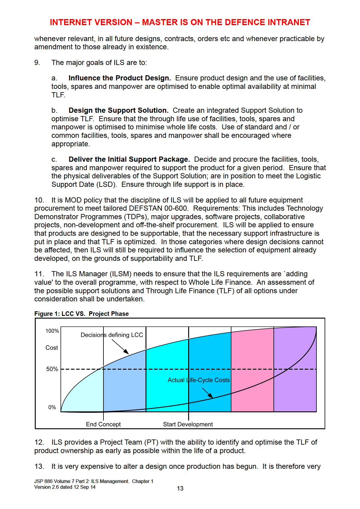
12 CHAPTER 1: INTEGRATED LOGISTIC SUPPORT MANAGEMENT POLICY CONTEXT 1. Integrated Logistic Support (ILS) is a methodology intended to assist in the formation of a robust Support Strategy and to aid the construction of a Support Solution. It does not contain the policies that a project may need to consider in developing a Support Solution, but it does contain the techniques and elements that need to be considered to construct the solution. ILS is applicable to product projects including upgrades, upkeep and also to a certain extent; Information Systems (IS) enabled business change programmes and Urgent Operational Requirements (UORs). 2. Using the assistance of a nominated Support Solution Improvement Team (SSIT) Officer and key stakeholders the ILS Manager must tailor the ILS programme to meet the project requirements. POLICY 3. The policy for ILS is promulgated in JSP 886 Volume 7 Part 1. PRECEDENCE AND AUTHORITY 4. Ownership of Logistic policy in support of the Logistic Process falls to the Assistant Chief of Defence Staff Logistics Operations (ACDS Log Ops) as CDM s Process Architect. This role is exercised through the Defence Logistics Policy Working Group (DLPWG) and the Defence Logistics Steering Group (DLSG) reporting up to the Defence Logistic Board (DLB). It is against this governance framework that sponsorship for T&TE policy is the responsibility of Director Training and Education (DT&E). PTs are required to assess and show compliance with key policies and governance as signposted by the SSE. MANDATED REQUIREMENTS 5. There are no mandated requirements for the management of ILS. REQUIREMENTS AND CONSTRAINTS Requirements 6. Details of any broad requirements, including relevant Force Support Requirements, defining the envelope in which the support solution shall be delivered. This shall maximise the opportunity to develop an innovative solution. Constraints 7. None Identified. KEY PRINCIPLES 8. ILS provides the disciplines for ensuring that supportability and cost factors are identified and considered as early as possible during the product lifecycle so that they may influence the design, with the aim of optimizing the Through Life Finance (TLF). DEFSTAN defines the Ministry of Defence (MOD) requirements for the application of ILS principles for through life management of product. It is intended to be used, JSP 886 Volume 7 Part 2: ILS Management. Chapter 1 Version 2.6 dated 12 Sep 14 12
13
14 important that the support requirements of every project are addressed from the inception of the Project. This may result in expenditure being incurred during the early stages of a project, in order to generate far greater savings downstream, as it is far easier and cheaper to change a design at the concept stage rather than after a product has been introduced into service. The cost profile is detailed in Figure 1. ASSOCIATED STANDARDS AND GUIDANCE 14. Reference and, if practical, link to the relevant publications involved. a. DEFSTAN : Integrated Logistic Support. Requirements for MOD Projects. b. JSP 886: Defence Logistic Support Chain Manual. c. PLCS: ISO10303-AP239 Project Life Cycle Support. d. OAGIS 9.0: Open Applications group Information Standard 9.0. e. ASD S1000D: International Specification for Technical Publications. f. ASD S2000M: International Specification for Materiel Management. g. ASD S3000L: Logistic Support Analysis. h. IEC : Dependability Management Part 3-12 Application Guide Integrated Logistic Support. OWNERSHIP AND POINTS OF CONTACT 15. The policy for ILS Management is sponsored by ACDS LOG Ops a. Enquiries concerning the technical content are to be addressed to: DES IMOC SCP-ILS2Tel: Mil: 9679 Ext 82689, Civ: b. General enquiries about accessibility of this instruction are to be addressed to: ACDSLOGOPSDefLogPol-JSP886@mod.uk Tel: Mil: 9679 Ext 80953, Civ: JSP 886 Volume 7 Part 2: ILS Management. Chapter 1 Version 2.6 dated 12 Sep 14 14

15

16

17
18 e. Return on Investment. 13. Service Design. Guidance for the design and development of services, Service Management processes and design capabilities for Service Management. Design principles and methods for converting strategic objectives into portfolios of services and service assets. Supporting processes within Service Design are: a. Service Catalogue Management. b. Service Level Management. c. Supplier Management. d. Capacity Management. e. Availability Management. f. Service Continuity Management. g. Information Security Management. 14. Service Transition. Guidance for the development and improvement of capabilities for transitioning new and changed services into operations. Additionally, guidance on managing the complexity to change to services and service management processes; preventing undesired consequences while allowing for innovation. Supporting processes within Service Transition are: a. Service Asset and Configuration Management. b. Change Management. c. Release and Deployment Management. 15. Additional processes are: a. Knowledge Management. b. Service Validation and Testing. c. Evaluation. 16. Service Operations. Guidance on achieving effectiveness and efficiency in the delivery and support of services so as to ensure value for the customer and the Service Provider. Additionally, guidance on how to maintain stability in Service Operations, allowing for changes in design, scale, scope and service levels. Supporting processes in Service Operations are: a. Event Management. b. Incident Management. c. Request Fulfilment. d. Problem Management. JSP 886 Volume 7 Part 2: ILS Management. Chapter 2 Version 2.6 dated 12 Sep 14 18
19 e. Access Management. 17. Within Service Operations there are the following Service Management Functions: a. Service Desk. b. Technical Management. c. IT Operations Management. d. Applications Management. 18. Continuous Service Improvement. Guidance on creating and maintaining value for customers through better design, introduction, and operation of services. Additionally, guidance in realizing incremental and large-scale improvements in service quality, operational efficiency and business continuity whilst linking improvement efforts and outcomes with Service Strategy, Service Design and Service Transition. 19. The use of Continuous Service Improvement techniques will ensure that the ITIL Framework remains an iterative cycle throughout all lifecycle phases. Figure 6: ITIL to Supportability Analysis (SA) Task Mapping. SA Activity Development of an early SA strategy SA Plan Programme and Design Reviews Use Study Mission Hardware, Software, Firmware & Support System Standardization Comparative Analysis Technological Opportunities Supportability & Supportability Related Design Factors Functional Requirements Support System Alternatives Evaluation and & Trade-off Analysis Task Analysis Impact on existing support system Post Production Support Analysis Supportability Test, Validation, Evaluation and Task Evaluation ITIL Phase Service Design Service Design Service Design Service Design Service Design Service Design Service Design Service Design Service Design Service Design Service Design Service Design Service Transition Service Transition Continuous Service Improvement MANAGE THROUGH LIFE SUPPORT [WBS00-00] Establish Support Programme 20. The support programme shall be initiated as early as possible in the concept phase of the CADMID / T cycle. MOD ILS Staff Requirement 21. A PT will normally include an ILS team to address ILS issues within the project. The size and structure of the Integrated Logistic Support (ILS) team will be dependent upon the type, size and complexity of the equipment project. 22. In principle, the PT leader will decide the composition of his team; however, there are several caveats to this: a. Before a PTL is selected the Capability Manager will have had to establish the JSP 886 Volume 7 Part 2: ILS Management. Chapter 2 Version 2.6 dated 12 Sep 14 19
20 PT start date, funding and, with personnel staffs, the initial manning. b. The manning of the ILS members of the team must, at each stage of the project's life, satisfy CDM and be sustainable. c. The expertise of available personnel will not necessarily be best suited to the fluctuating needs of the project; the PT leader may need external assistance / manpower substitution. d. The PTL shall determine the appropriate staff levels and areas of expertise required for the ILS team and take appropriate establishment action to ensure supportability aspects of the programme are fully supported. Appointment of an ILS focus of equivalent grade commensurate with the project shall be achieved as early as possible. The requirement for personnel to hold ILS licences shall be identified. e. The MOD ILS Manager (MILSM) (or Supportability Analysis (SA) manager as appropriate) must ensure that those SA activities which are the MOD's responsibility during the Concept stage are completed. They shall also select the appropriate SA tasks to be undertaken by Industry (and MOD) for inclusion in the ILS Strategy (and subsequently the ILS Plan) and ILS SOW for the Assessment stage. 23. The ILS Management Organisation shall include provision for the following: a. In all but the smallest projects, an ILS Manager shall be appointed by the PTL, normally one grade below the project managers status. Where the task does not warrant this level of input, the appropriate DE&S operating centre has created ILS project support teams that are tasked to provide PTs with ILS advice and technical assistance. b. Depending on the size of the project, the MILSM will form a team to cover some, or all of, the following disciplines: (1) Supportability Analysis (SA). (2) Logistic data management. (a) (b) (c) (d) (e) (f) (g) (h) (i) Technical information / publications. Supply Support Procedures. Support and Test Equipment (S&TE). Training and Training equipment (T&TE). Packaging, Handling, Storage and Transport (PHS&T). Human Factors Integration (HFI). Facilities and infrastructure. Through Life Finance. Reliability and Maintainability (R&M). (3) For large and complex projects it may be appropriate to base a field team JSP 886 Volume 7 Part 2: ILS Management. Chapter 2 Version 2.6 dated 12 Sep 14 20

21
22 difficult task. This is especially true when trying to cope with design changes, requirement changes and cost reductions at the same time. DOs and DONTs 28. As the ILS guardian, there are certain things that a MILSM shall try to achieve and some things that are best avoided. 29. The MILSM shall: a. Become an integral part of the PT. b. Ensure supportability and TLF issues influence the design. c. Ensure that the supportability implications of the design are identified, planned for and managed within the project. d. Ensure that a pragmatic approach is taken to implementing ILS to suit the project's needs. e. Ensure compatibility with existing or projected support infrastructure and constraints. f. Ensure the support package is available when required. g. Identify and align support and design team interfaces. 30. The MILSM shall not: a. Start to do too much too soon. b. Allow supportability issues to be ignored. c. Attempt to rule the world with supportability issues. d. Create data for data's sake. Develop / Appoint the ILS Team 31. Small projects may only need an ILS team consisting of only one person relying on additional specialist advice, guidance and assistance from the Support Solutions Improvement Team (SSIT). For the more complex projects, an ILS team might consist of some or all of the following posts at different phases of the CADMID cycle: a. ILS Manager. b. ILS Engineer. c. SA Manager. d. Supply Support / Materiel. e. Fielding. f. Subject Matter Experts (SMEs). JSP 886 Volume 7 Part 2: ILS Management. Chapter 2 Version 2.6 dated 12 Sep 14 22
23 Project ILS Staff Requirements 32. The Role of the ILS Manager: a. A MOD Integrated Logistic Support Manager (MILSM) is appointed to the management team of an equipment project by the PTL to provide a support perspective to the activity and decisions of the PT. b. The MILSM undertakes a number of tasks to ensure that ILS principles are considered and applied to equipment acquisition. c. The MILSM is normally directly responsible to the PTL. It is normal for the MILSM to be accorded equal status with other functional area managers. d. The MILSM is usually made responsible for planning and procuring the logistic support aspects of the project on behalf of the PTL. This includes advising the Sponsor on equipment supportability issues and managing the ILS programme on behalf of the PTL. e. Stakeholders must be kept informed of the status of ILS activity and their agreement obtained before any decisions are made that might adversely affect supportability objectives. These responsibilities are affected via a Logistic Support Committee (LSC), chaired by the MILSM with representatives from all Stakeholders. Industrial representation may be placed in abeyance during competitive phases of contract development. f. In addition to his principal responsibilities to the PTL, the MILSM also has a functional responsibility to the User to ensure that the project pursues a support strategy that is compatible with current service policy on equipment support, as promulgated by the User, agreed with the Sponsor and specified in the Project Requirements Set. 33. The MILSM usually undertakes the following tasks: a. Prepare a number of documents to define and support the ILS strategy for the project. These include: (1) ILS Strategy. (2) ILS Plan.SA Strategy. (3) SA Plan. (4) Use Study. (5) Statement of Work for Assessment phase requirements. (6) Work Breakdown Structure. (7) Manage the duties and activities of the ILS team and any dedicated administrative support, against management objectives detailed in the ILSP. (8) Provide the interface for the PT with all logistic support agencies. (9) Provide the point of focus within the PT for logistic support agencies. JSP 886 Volume 7 Part 2: ILS Management. Chapter 2 Version 2.6 dated 12 Sep 14 23
24 (10) Provide the ILS focus for contractors associated with the project. (11) Initiate / maintain an ILS history as part of the overall project history, together with an ILS lessons learned register; (12) For an international or inter-service collaborative project, provide the point of contact for logistic support matters between the lead / international project office, the UK project office, national agencies and national contractors. (13) Provide the logistic support input to all project papers, reports and submissions. (14) Develop the support strategy, as part of the overall Procurement Strategy, against the programme baseline. (15) Include supportability requirements in all plans and programmes, including Technology Demonstrator Programmes, Development Trials, Request for Proposals, Invitation to Tenders, Tender Assessments and Contract Specifications. (16) Provide the logistic input into all reliability and maintainability activity. (17) Identify and define support funding for all supportability aspects throughout the equipment's life cycle and seek inclusion in LTC bids and submissions; (18) Assist the relevant OR branch in the development of the Use Study. (19) The MILSM shall ensure that supportability aspects are represented at: (20) Logistic Support Committee (as chairman). (21) Configuration Change management Committee. (22) Reliability Panel. (23) Project Management Committee. (24) Design Reviews (including in-service). (25) ILS / SA reviews. (26) Other meetings as directed by the PTL. 34. A MILSM shall consider the formation of sub-groups reporting to the LSC for the following areas: a. Training & Training Equipment. b. Packaging, Handling, Storage and Transport (PHS&T). c. Reliability Panel. d. Technical Information (TI). e. Support and Test Equipment ( S&TE). JSP 886 Volume 7 Part 2: ILS Management. Chapter 2 Version 2.6 dated 12 Sep 14 24
25 f. Disposal & termination. g. Facilities. h. Human Factors Integration (HFI). i. Supply Support Procedures. j. Configuration Management (CM). k. Obsolescence Management (OM). l. Safety and Environmental Protection (S&EP). 35. The MILSM shall ensure that the contractor(s), in preparing their Integrated Support Plan (ISP) examine the SA tasks specified in the Invitation to Tender document (ITT), Statement of Work (SOW) or contract. Contractor Staff Requirements 36. The contractor shall develop a team of personnel that in broad terms shadow the responsibilities of the MOD project staff. The contractor ILS team must demonstrate that they understand the project requirements and have the authority to influence the project design for supportability. a. Industry shall be involved from the earliest phases of a project and actively encouraged to participate in the trade-offs between performance, cost, time and supportability. b. During the Concept stage, Industry is more likely to be co-opted on to the PT, rather than being an integral member in the fullest sense. c. The involvement of companies as early PT members shall itself help with developing meaningful acquisition and ILS strategies for the assessment phase. Establish ILS Requirements 37. The ILS requirements for the product under development will be developed from the proposed usage scenarios identified by the Sponsor. The ILSM needs to ensure that the ILS requirements are `adding value' to the overall programme, with respect to Through Life Finance. As the project progresses, these requirements will become better defined and will ultimately become the quantified ILS requirements within the project requirement set. Project Phases 38. The types and level of detail of requirements to be captured will vary dependent upon the project phase. In the early stages requirements will be high level. When going into the Manufacturing Phase the low level logistic information deliverables will be captured as requirements. Requirements Capture 39. Requirements Capture is one of the key activities in providing the supportability input to dossiers and other submissions. Properly recording these requirements and their justification will aid the MILSM in the following tasks: JSP 886 Volume 7 Part 2: ILS Management. Chapter 2 Version 2.6 dated 12 Sep 14 25
26 a. Invitation to Tender (ITT) development to ensure that all requirements are called up by the ITT. b. Tender Marking-to check that the response is compliant, or for assessing alternatives proposed by the bidders. c. Checking that the deliverables meet the requirement and where more than one contractor is involved, comparing their performance. 40. In Service Original requirements can be traced when equipment is failing in service or when modifications to equipment or the support system are proposed. 41. Properly recording requirements at project inception and recording and justifying changes during each phase will ensure that requirements are not lost when preparing the submission for the next phase. 42. When most people think of Requirements Capture they think of specifications and standards. Whilst speed, endurance and availability are all important, the MILSM must consider what information he will need to buy during the later stages of the project to support the equipment through life. The ILS / SA tasks and their associated outputs must all be documented as requirements as the project progresses. 43. At the start of each project phase there shall be an agreed set of project requirements. Consideration shall be given to both functional and non functional requirements at each project stage. Requirement Changes 44. The requirements which the MILSM places on the contractor will change throughout the life of a project. In most cases they will remain fundamentally the same, but the details and the granularity of the information will vary with the project phase. Outside influences can also impose changes. Throughout the project it is necessary that requirements shall be recorded and managed so that their development and provenance is documented. Outside Influences 45. Factors outside the control of a traditional Project Team can also significantly change the support requirements. These could include such things as: a. Modification of the operational role (Sponsor). b. Changing the maintenance \ upgrade cycle of the platform (Platform PT Representative). c. Integrating with a different platform (PT leader in consultation with the relevant Platform PTLs). d. Changing the operating or maintenance base (Sponsor). e. Manpower changes, including training and branch structure (User). f. Changes imposed by higher government authorities. g. Environmental requirements (National or International legislation). JSP 886 Volume 7 Part 2: ILS Management. Chapter 2 Version 2.6 dated 12 Sep 14 26
27 Develop ILS input to User Requirement Document (URD) 46. The URD defines the user requirement in the form of the outputs or results that the users require from the system. The ILS Manager shall provide the appropriate inputs to and support for the Support Focus of the Project URD, Including: a. Project Supportability Objectives. b. Project Support Concept in the Support Strategy Paper for the Business Case. c. The Systems Requirement Document (SRD) is developed from the user requirement to define the system requirement i.e. what the system must do to meet user needs. The MILSM must: d. Ensure that the SRD includes the detailed support strategy developed by the ILS team in response to the URD support requirements. e. Identify and justify Supportability Objectives. 47. Supportability requirements shall be included in the Requirements Database which forms the basis of the URD and SRD. When developing the requirements documents, the ILSM shall be invited to the Capability Working Group (CWG) to ensure that supportability issues are addressed. He shall be prepared to put forward the justification for the inclusion of the supportability requirements statement as one of the Key User Requirements (KUR) for the system. 48. The supportability inputs to the URD are defined as non-functional requirements, and define the support environment within which the equipment will be required to operate. Any deviations require justification. Deviations may also arise from user requirements, technical disciplines or the external environment and can be divided into product or support. They include the following areas: a. Operability. b. Safety. c. Security. d. Engineering standards. e. Environment. f. Support. 49. Early identification of these requirements will avoid costly changes later and facilitate the trade-off process leading to a cost-effective solution. Blanket application of individual non-functional requirements will be unnecessarily costly and shall be avoided. They shall be identified against and linked to the lowest level function in the decomposition to which they specifically apply. Non-functional requirements shall also be expressed as unique statements of requirement with the same attributes as system functions. Develop ILS input to System Requirement Document (SRD) 50. The SRD is developed from the user requirement to define the system requirement - what the system must do to meet user needs. The MILSM must: JSP 886 Volume 7 Part 2: ILS Management. Chapter 2 Version 2.6 dated 12 Sep 14 27

28
29 Figure 9: Support Maturity Level (SML) Definitions SML Milestone Definition User Requirement Documented Contractual System Requirements Documented Preliminary Design Review Critical Design Review Support Solution Validated Logistics Support Date In-Service Date In-Service Support Verification Out of Service Date The URD defines the User requirement in the form of the outputs or results that the Users require from the system. The ILS Manager shall provide the appropriate inputs to and support for the Support Focus of the Project URD including: Project Supportability Objectives Project Support Concept in the Support Strategy Paper for the Business Case The Systems Requirement Document (SRD) is developed from the User Requirement to define the system requirement i.e. what the system must do to meet User needs. The SRD is developed from the user requirement to define the system requirement - what the system must do to meet user needs. The MILSM must: Ensure that the SRD includes the detailed support strategy developed by the ILS team in response to the URD support requirements. Identify and justify Supportability Objectives. Include Supportability aspects in the Requirements Database which forms the basis of the URD and SRD. When developing the requirements documents the ILSM shall be attend the Capability Working Group (CWG) to ensure that supportability issues are addressed. The MILSM will put forward the justification for the inclusion of the supportability requirements statement as one of the Key User Requirements (KUR) for the system. The SRD is the basis for the initial Statement of Work (Sow). Through the procurement process the SOW is negotiated until final bids can be made based on the final SOW which in turn is based on the refined SRD. This is the Contractual SRD The Preliminary Design Review demonstrates that the preliminary design meets all system requirements with acceptable risk and within the cost and schedule constraints and establishes the basis for proceeding with detailed design. It will show that the correct design options have been selected, interfaces have been identified, and verification methods have been described. The support solution system requirements are likely to be well understood at this point The CDR demonstrates that the maturity of the design is such that it is appropriate to proceed with full-scale fabrication, assembly, integration and test. CDR determines that the technical effort is on track to complete the capability development, to meet mission performance requirements within the identified cost and schedule constraints. Support Maturity Level 5 is the point at which the support solution has been validated. This is likely to involve evidence from engineering evaluation and test and demonstration of the support solution The LSD is defined as the support solution is in place with the appropriate range and scale to support the initial delivery of a capability and a plan is in place to meet the roll out of the Capability. The ISD is defined as the support solution is in place in range and scale to meet and sustain the full operation of the support solution. An early In-Service Support Review should be instigated to verify that the support solution is working in service Subsequent ISS Reviews are required to ensure continued best value and when it is necessary to refine the support solution when changes occur This is the date when the capability has been decommissioned. Technology Readiness Levels (TRL) 56. TRLs are a Technology Management tool that provides an indication of the technical maturity of a project by identifying risk associated with technology and system integration. They have a graduated scale that uses specific criteria to define the maturity of technology. 57. TRLs are an important consideration when conducting Supportability Analysis, particularly during trade off analysis and must be considered when developing a support system. JSP 886 Volume 7 Part 2: ILS Management. Chapter 2 Version 2.6 dated 12 Sep 14 29
30 58. TRLs are strongly coupled to certain ILS elements, such as obsolescence management and can be a significant support solution cost driver. System Readiness Levels 59. A System Readiness Levels (SRL) is a score between 1 and 9 that communicates a project s System Maturity against the systems engineering V Diagram (CADMID). 60. However, SRLs are evidence based and also inform the assurance of projects at key decision points. To move through Initial Gate evidence must be available to demonstrate that the project is sufficiently mature. 61. It is the ILS Manager s responsibility to ensure that the project system engineering definitions used when calculating the SRL take cognisance of the associated support system. 62. The ILS supportability case must be taken into consideration when determining the SRL. Further information on TRLs and SRLs is detailed in the AOF. Develop Use Study 63. The MOD Architectural Framework (MODAF) defines a number of documents during the Applied Concepts stage of Concept & Doctrine development within the framework. Further detail may be found a DCDC applied concepts guidance: a. Concept of Operation (CONOPS). CONOPS describe how a range of (future and where necessary extant) capabilities is used in a future operational context to solve a particular problem or capability gap. CONOPS are refined and validated by concept development work and, at the time of their endorsement by Policy & programme Steering Group (PPSG), will have demonstrated sufficient maturity to stand as guidance to the Defence Planning and EC communities. Joint Operations Concept Committee (JOCC) Joint and environmental staff are responsible for the generation of the majority of CONOPS. Normally produced in the concept phase. b. Concept of Employment (CONEMP). CONEMP is the Applied Concept of employment for a specific capability within a range of operations or its focus is Epochs 1-3 and it will be produced by Joint and single-service User. Normally produced in the assessment phase. c. Concept of Use (CONUSE). A CONUSE describes the way in which specific equipment is to be used in a range of operations or scenarios. Normally produced in the development phase. 64. The Use Study and the CONUSE are synonymous and only one document shall be in existence within a project. For projects that have not been generated against the current policy and do not have a CONUSE then the ILS manager must generate a Use Study. 65. DEFSTAN requires the Use Study \ CONUSE to be updated through life and be revisited if the acquisition lifecycle is re iterated for mid life upgrades. 66. The Use Study provides the data that must be supplied by the MOD to the contractor so that he can carry out his tasks. Much of this data could be included in the requirement specification, and indeed the more quantitative requirements are often included in the JSP 886 Volume 7 Part 2: ILS Management. Chapter 2 Version 2.6 dated 12 Sep 14 30
31 SRD.A typical use study includes the following information: a. Training Facilities. b. Available repair facilities by maintenance line. c. Manpower availability, skill levels, responsibilities, limitations. d. Existing training courses, skill requirements, etc. e. Additional sources of information, locations of field visits where actual existing systems can be examined. f. The use study shall address both peace and war time scenarios. g. A sample Use Study template is included at Annex H. ILS Strategy 67. The aim is to establish the major objectives of the ILS / SA programme. In other words what type of equipment is being procured, what specifications it must meet and how is it to be supported. This will enable the MILSM to determine the ILS Strategy and tailor the SA requirements. The selection of a specific ILS / SA strategy will be a balance between the objective of identifying and optimising the support requirements and the cost of achieving this, remembering that one of the aims of ILS is to optimise TLF. Unless care is taken, the benefits achieved by ILS / SA can be exceeded by the costs of achieving them. The ILS Strategy document identifies what tasks will be undertaken at each stage of a project cycle, which has responsibility for completing those tasks and how the support resources will be accepted. 68. The strategy sets the foundation of the ILS / SA programme and formalises interfaces with related programmes, (eg. R&M), ILS / SA tasks to be performed and integrates the ILS / SA products required in a consistent and cost effective manner. In particular, the support recommendations from the associated SA process need to be converted into actual deliverables which will enable the equipment to be supported and operated effectively throughout its life cycle. 69. An ILS strategy will be dependant on the method of acquisition, which can be described in broad terms by one of three different strategies: a. Development Item (DI). A completely new item designed and developed when existing systems or equipment cannot meet the Operational Requirements (ORs), this is usually referred to as a Development Item (DI). It is designed to meet the customer s performance specifications. Logistic support requirements must be developed concurrently with the design. An in-depth ILS programme is required to determine and develop the necessary logistic support for the item. Because the design is fluid, there is the greatest amount of freedom for the ILS process to influence design and it is essential to influence it from a supportability standpoint as early as possible. b. Non Development Item (NDI). A Non Development Item (NDI) is an item that has already been developed and is available and capable of meeting ORs. The equipment will have completed its research and design stages and will not be subject to a development cycle. NDI projects require evaluation of existing data and support JSP 886 Volume 7 Part 2: ILS Management. Chapter 2 Version 2.6 dated 12 Sep 14 31
32 concepts to identify areas needing additional analysis and data generation. As there is little or no influence on the design of the equipment, ILS will concentrate on optimising the support. An NDI would typically proceed through a condensed procurement process. c. Military Off The Shelf (MOTS). This is a subset of NDI, where the equipment has been developed to a military standard for another customer or as private venture by a defence equipment manufacturer. The data to perform ILS may not be available in the format compatible with the MOD preferred standards, but there may be information supplied to another military customer that could be adapted or reused. Although the ILS process will probably not influence the design, the process may be used to: (1) Evaluate existing information and support concepts to identify areas needing additional data analysis and generation. (2) Evaluation of support packages supplied to other military customers to evaluate whether it could be tailored to MOD needs. (3) Select the contractor by comparison of the support costs within the through life cost activities. d. Commercial Off the Shelf (COTS). This is a subset of NDI, where the equipment has been developed to commercial rather than military standards, with minimal MOD influence on the design. The data to perform other aspects of ILS may not be available from commercial sources. If such information is required it may need to be calculated, predicted or measured on delivered equipments. This procurement strategy often applies to equipments that have established, commercial, support packages available, but they may need modifying to meet MOD requirements. Although the ILS process will probably not influence the design, the process may be used to: (1) Evaluate existing data and support concepts to identify areas needing additional data analysis and generation. (2) Select the contractor by comparison of the support costs within the through life cost activities. (3) A sample ILS strategy template is included at Annex J. Urgent Operational Requirement (UOR) 70. ILS shall be applied to UORs just like any other acquisition project. The primary difference between UORs and a normal procurement is that the logistic support date may well be after the in service date. 71. The ILS activities to be conducted are the same as for any normal procurement, however the depth to which they are conducted and the timing of the SA tasks may be very different to a normal programme. 72. Serious consideration shall be given to what innovative support solutions may be available from the supplier in such circumstances. 73. A programme of work will need to be developed to ensure that Logistic Support Date JSP 886 Volume 7 Part 2: ILS Management. Chapter 2 Version 2.6 dated 12 Sep 14 32
33 is a close as possible to the in service date. An unsupported equipment is generally incapable of meeting its intended military capability and the support requirements shall not be traded off against other requirements without a rigorous risk analysis. Initiate Supportability Case 74. As soon as the project has identified support related requirements it is in a position to start documenting the activities intended to satisfy them in the supportability case. 75. Initially very little materiel will need to be recorded in the supportability case. Guidance on the production of a supportability case is detailed In JSP 886 Volume 7 Part 9. ILS PLANNING TO INITIAL GATE Develop Support Concept [WBS 01-01] 76. Detailed guidance on the Supportability Analysis Process that may be used to develop the ILS Product is detailed in JSP 886 Volume 7 Part 3. Other international standards such as ASD S3000L also contain acceptable methodologies for conducting the supportability analysis. 77. Development of the support concept starts at the beginning of a project s life when initiated by the ILS Plan. It proceeds iteratively in parallel with: a. The design of the ILS Product that will meet the capability requirement. b. The initial definition of potential support solutions by the Support Solution Definition and Optimize Support Performance processes. c. Is guided by the Support Solutions Envelope (SSE) Key Support Areas (KSAs) and Guiding Principles (GP s) including consideration of support solution optimization. d. Concludes its initial iteration before Initial Gate submission. e. May be repeated later in the programme life cycle in response to changes to the process inputs. 78. The inputs to the process are: a. Programme information. b. Requirements contained within Operating Requirements, the Capability Requirement and the URD. c. The required operational and support environments in which the required ILS Product are expected to be used. d. The required usage of the ILS Product. e. Any specific operational support related requirements. f. Any constraints that are imposed on the new ILS Product and its support system. JSP 886 Volume 7 Part 2: ILS Management. Chapter 2 Version 2.6 dated 12 Sep 14 33
34 g. The ILS Product functional and physical design information as it progressively develops during the concept phase of the programme. h. Support solution definitions and support experience from previous programmes. i. TLS management plans or programme directives, derived from Policies. 79. Any other TLS agreements, standards, strategies, policies or procedures applicable to the program in question. 80. The output from the process is a set of information that contributes to the PT s Support Solution Statement that then enables the PT to initiate Support Solution Definition development and Life Cycle Costing to the level of detail required for its Business Case to proceed to the Initial Gate IAB. This information set consists of: 81. Identification of the deployment environments for which support is required. (A deployment environment is a combination of the ILS Product, customer, and operating/support environment/location). 82. A set of one or more alternative support concepts that need to be explored for each deployment environment. A support concept is the combination of: 83. Identification of the contracting strategies to be applied or explored for any aspect of support (eg SOM options). 84. Guidance on the lines and levels of maintenance that shall be explored or applied to any specific elements of the ILS Product requiring support. 85. The initial specification of the supportability, cost and readiness metrics that will be used to assess the design of the support solution and the performance of the support system when it becomes operational. 86. Inputs to the process. TLS Plan and ultimately the Through Life Management Plan (TLMP), including the associated Master Data and Assumptions List (MDAL). This includes the identification of supportability requirements, constraints, and recommendations wrt the need for logistic support analyses such as Failure Modes Effect Criticality Analysis (FMECA), Reliability Centred Maintenance (RCM), Level of Repair Analysis (LORA), LCC, and Scaling. 87. Initial ILS SOW, WBS and ITT, that will be required in order to decide which concepts to evaluate further and develop into support solution definitions. 88. Feedback on issues with: a. Supportability requirements, constraints and objectives. b. The ILS Product functional and physical design, including hardware and software standardization information and recommendations. Support Options Matrix (SOM) 89. The SOM was developed for PTs by the Equipment Support Continuous Improvement Team (ESCIT). The SOM is used to identify support chain options by reviewing effectiveness and efficiency gains. It also identifies key performance and cost JSP 886 Volume 7 Part 2: ILS Management. Chapter 2 Version 2.6 dated 12 Sep 14 34
35 drivers, and indicates who is best placed to manage those drivers either industry or MOD. 90. The SOM is the MOD s current preferred framework for the design/improvement of (equipment/system) support chains. The SOM is somewhat granular and provides the following options: a. Spares Exclusive Upkeep (SEU). b. Spares Inclusive Upkeep (SIU). c. Incentivised Upkeep Cost Reduction (IUCR). d. Incentivised Reliability Improvement (IRI). e. Asset Availability Service on balance sheet (AAS on B/S). f. Asset Availability Service off balance sheet (AAS off B/S). g. Capability Service off balance sheet (CS off B/S). h. Capability Service off balance sheet (CS off B/S). 91. Generally the SOM is used as an idealistic starting point and real world solutions are often an amalgam of a number of approaches for different systems and equipment within an equipment programme. Figure 10: Support Options Matrix Capability service (off balance sheet) Capability service (on balance sheet) Asset availability service (off balance sheet) MOD pays Industry to underwrite the delivery of an MOD defined capability. Assets on Industry B/S as shared with 3rd party beneficial users MOD retains ownership of defining capability upgrades MOD retains ownership of safety legislation adherence Industry involvement in forward UPKEEP and LOGISTICS processes is more likely but is still dependant on the expected operational environment. Industry takes ownership of all other aspects of the support chain. MOD pays Industry to underwrite the delivery of an MOD defined capability. Assets on MOD B/S as there is no 3rd party beneficial user MOD retains ownership of defining capability upgrades MOD retains ownership of safety legislation adherence Industry involvement in forward UPKEEP and LOGISTICS processes is more likely but is still dependant on the expected operational environment. Industry takes ownership of all other aspects of the support chain. MOD pays Industry for availability of serviceable, Industry owned assets at a specific point in the support chain (usually the depth-forward boundary) Industry owns the assets and is therefore responsible for configuration control and technical documentation. Industry given additional freedom to plan & execute depth UPKEEP requirements, adjust the maintenance policy, and manage UPDATE UPDATE and technical support included in the availability contract Requires industry to develop engineering and support chain integration capabilities MOD defines the availability requirement; requires safety and fit for purpose assurances and exit strategy Industry involvement in forward UPKEEP processes is dependant on the operational environment. JSP 886 Volume 7 Part 2: ILS Management. Chapter 2 Version 2.6 dated 12 Sep 14 35
36 Asset availability service (on balance sheet) Incentivised reliability improvement Incentivised upkeep cost reduction Spares inclusive upkeep Spares exclusive upkeep MOD pays Industry for availability of serviceable, MOD owned assets at a specific point in the support chain (usually the depth-forward boundary) Industry given additional freedom to plan & execute depth UPKEEP requirements, adjust the maintenance policy, and manage UPDATE UPDATE and technical support included in the availability contract Requires industry to develop engineering and support chain integration capabilities MOD defines the availability requirement; requires safety and fit for purpose assurances and exit strategy Industry involvement in forward UPKEEP processes is dependant on the operational environment. MOD pays Industry for labour, overheads and spares consumed during depth UPKEEP Industry given freedom to design & embody modifications to improve reliability. MOD plans UPKEEP requirements, Industry executes 'depth' UPKEEP Industry plans spares requirements and procures spares for depth UPKEEP and reliability modifications UPGRADE, technical support and non-reliability aspects of UPDATE contracted separately Requires longer term contract duration and better MOD forecasts of UPKEEP load Requires industry to develop engineering capability to reduce UPKEEP arisings Requires mechanism to share benefits of reduced UPKEEP arisings Requires safety and fit-for-purpose assurance for MOD MOD pays Industry for labour, overheads and spares consumed during depth UPKEEP Industry given freedom to change UPKEEP work scope, generate component repair schemes and amend test acceptance limits MOD plans UPKEEP requirements, Industry executes 'depth' UPKEEP Industry plans spares requirements and procures spares for depth UPKEEP UPDATE, UPGRADE and technical support contracted separately Requires longer term contract duration and better MOD forecasts of UPKEEP load Requires industry to develop engineering capability to reduce UPKEEP cost Requires mechanism to share benefits of reduced UPKEEP cost MOD pays Industry for labour, overheads and spares consumed during depth UPKEEP MOD defines all aspects of UPKEEP policy MOD plans UPKEEP requirements, Industry executes 'depth' UPKEEP Industry plans spares requirements and procures spares for depth UPKEEP UPDATE, UPGRADE and technical support contracted separately Requires longer term contract duration and better MOD forecasts of UPKEEP load Requires industry to develop spares provisioning capability Requires mechanism to share benefits of lower spares costs and reduced UPKEEP TRT MOD pays Industry for labour & overheads consumed during depth UPKEEP MOD defines all aspects of UPKEEP policy MOD plans UPKEEP requirements, Industry executes 'depth' UPKEEP MOD plans spares requirements and procures spares for depth and deployed UPKEEP UPDATE, UPGRADE and technical support contracted separately 92. The above list denotes a hierarchy where contracting for capability is most desirable under the current political trend. There is a risk that the optimal solution is ignored in pursuing this dogma and tasks are contacted out at greater expense than can be achieved by traditional methods. In practice support solutions for complex projects may evolve which also vary in approach across the different ILS elements and the resulting support solutions may not sit comfortably one SOM option. JSP 886 Volume 7 Part 2: ILS Management. Chapter 2 Version 2.6 dated 12 Sep 14 36
37
38 the equipment and has complete ownership and control of the support solution. 98. In a traditional solution the human resource is often provided against different considerations than the support solution need, usually the available military manpower is driven by operational considerations. The skill set available will be limited to what the military can provide and not necessarily be the optimum to support the equipment. 99. The use of this approach has the benefit of authority personnel maintaining skill levels and removing the need for accurate feedback to the contractor There are no CONDO considerations The traditional military supply chain is used and there are no problems with direct delivery and lack of visibility of goods within the pipeline. All items are NATO codified. Spares Inclusive Upkeep (SIU) 102. SIU may be applied either as an interim of a selective CLS solution Where equipment is repaired through CLS at 4th line the authority loses visibility and control. Contracts based on long-term availability measures have the risk that a contractor may deliberately barely meet their obligations and have no surge capacity within the system; this may conflict with operational requirements Spares costs are usually on a fixed price basis against a known timeline, this may ease budgetary uncertainty and allow costs to be spread potentially reducing the initial procurement cost, and the value of regular cash flow to a commercial organisation must never be underestimated. Incentivised Upkeep Cost Reduction (IUCR) 105. Industry is incentivised to develop engineering capability to reduce Upkeep cost. Industry given freedom to change Upkeep work scope, generate component repair schemes and amend test acceptance limits. MOD plans Upkeep requirements, industry executes 'depth' Upkeep MOD pays Industry for labour, overheads and spares consumed during depth upkeep. This approach requires a partnering approach with a degree of open book accounting to share benefits of reduced Upkeep cost. The authority pays Industry for labour, overheads and spares consumed during depth Upkeep. Requires longer term contract duration and better MOD forecasts of Upkeep load Industry plans spares requirements and procures spares for depth upkeep. Post deign services activity including Update, Upgrade and technical support are contracted separately. Incentivised Reliability Improvement (IRI) 108. Industry is incentivised to develop engineering capability to improve reliability. Industry given freedom to change design & embody modifications to improve reliability. MOD plans Upkeep requirements, industry executes 'depth' Upkeep MOD pays Industry for labour, overheads and spares consumed during depth Upkeep. This approach requires a partnering approach with a degree of open book JSP 886 Volume 7 Part 2: ILS Management. Chapter 2 Version 2.6 dated 12 Sep 14 38
39 accounting to share benefits arising from improved reliability. The authority pays Industry for labour, overheads and spares consumed during depth Upkeep. Requires longer term contract duration and better MOD forecasts of Upkeep load Upgrade, technical support and non-reliability aspects of update contracted separately The Authority cannot totally transfer the operational risk of failure to the contractor and thus will require a means of assuring that the solution is safe and fit-for-purpose. Asset Availability Service on/off balance sheet (AAS on/off B/S) 112. An availability contract in its purest form has the contractor deliver the complete system including all support but not the operation of the system Along with consideration ownership of assets of the system itself ownership of repair facilities and the IPR inherent within support chain procedures and processes shall be considered The risk of delivering an acceptable level of availability theoretically remains with the contractor and as such the contractor is presumed to be incentivised to employ the optimum solution. It is assumed that the contractor will seek to improve system availability and performance In practice the risk for a significant military capability will always return to the authority, therefore the authority may require evidence to support a level of confidence in a contract being achieved as the financial risk to the contractor may be insignificant compared to the operational risk for the authority, certain military capability gaps would be viewed as unacceptable under any circumstances The theory is that the contractor is not hindered by bureaucratic MOD procedures and over complicated processes and can quickly implement improvements to achieve the contracted level of availability The contractor is normally incentivised by contract clauses to improve performance, these clauses will need to be both feasible and measurable and unambiguously understood by both parties or the authority has the risk that the contract cannot be enforced Consideration in the contract must be given to support chain operation in times of conflict; these restrictions are constrained by the CONDO limitations Using a CLS support solution will usually involve a lower capitation rate than the equivalent military or civil service staff and remove the authority from any associated recurring training liability as staff turnover. The culture of the MOD results in lot of manpower churn particularly for military staff, where a two year posting is the norm. Increasing contractor involvement may result in skill fade within the military, which may prove difficult to economically restore. Capability Service On/Off Balance Sheet (CS On/Off B/S) 120. In full Capability service CLS the authority contracts for the delivery of an entire capability to cost and performance including operation of the equipment\service. Most of JSP 886 Volume 7 Part 2: ILS Management. Chapter 2 Version 2.6 dated 12 Sep 14 39
40 the issues identified for an availability contract also apply to Capability based CLS. This is a highly attractive option for projects that have limited ILS resources to develop a support solution; however care has to be taken not to abdicate responsibility with proper risk management This CLS option is limited more than any other by CONDO policy which limits its application to no combat locations The decisions surrounding the provision of the primary system or service and the associated support solution is left entirely at the discretion of the contractor. The contractor owns virtually all the risks and is free to manage them accordingly The risk to the authority is that contract failure will lead to a military capability gap existing which without a strong exit strategy the authority can only realistically fill by starting with another contractor or building an in house capability. The risk to the authority of over dependence on the contractor will need to be very carefully evaluated Care has to be taken when enfettering long term partnering capability based CLS arrangements that long term commercial competition in the market place is not stifled. Contract Management Considerations 125. The management and control of the contract is usually linked to payment at an appropriate level often incentivised through some staggered threshold stratagem or pro rata. A real risk for the authority is for a contract to be written which can be fulfilled whilst not affording the required operational availability; a capability gap will exist though payment must continue. The authority may offer dividend payments based on superior performance but will usually cap this and validate that value for money is being received Including Work-In-Progress within the annual cost certificate allows better budgetary management, preventing payments from slipping into following Financial Years. Contract Granularity 127. Whilst the strategy of setting out high level contractual requirements is a valid objective, this sometimes needs to be supported by explicit conditions, especially where the contractor is taking on new tasks. Precise definition of contractual requirements is essential to avoid disputes caused by misconception of who is responsible for delivering what. Complicated arrangements such as core/non-core activities shall be avoided Intense maintenance periods Planning and control methods shall be explicitly detailed. Term of Contract 129. Long term contract approaches are considered positive. Appropriate contract period and review points enable a proactive approach by both parties. With improved financial forecasting for customer and more stable work load for contractor. Frequent changes in support contracts prevent contractors forming strong / effective working relationships with MOD employees and a dislocation of corporate knowledge Contract performance in CLS arrangements usually improves when a full partnering relationship is engendered. This has shown to be true for the some platform CLS contracts where 'the support solution came together when the contract was ripped up and JSP 886 Volume 7 Part 2: ILS Management. Chapter 2 Version 2.6 dated 12 Sep 14 40
41 both parties formed a partnering arrangement to get on with the task both of them knew had to be done'. This situation is largely personality driven and requires the right team to create a supportive organisational culture The key drivers for decision making within commercial organisations were not historically well understood by MOD. An example of this is where MOD has distracted the contractor from the primary purpose by demanding information that was simply not cost effective to answer. A pragmatic understanding of commercial reality is important. Flexibility 132. The contractor will inevitably monitor equipment usage to ensure that it is being used within the limits of the contract. It is conceivable that the equipment will be used outside of contracted usage boundaries in an operational context and invalidates the contract. A means of negotiating deviation from the context will need to be agreed. The situation where either party hides behind a contract will not produce any long term benefits. Novation Issues 133. Any support solution that does not start from the inception of the project may need to transfer contractual responsibilities from one commercial organisation to another. The novation of these contractual responsibilities may prove problematical as they might not suit the business interests the original commercial partner Any cost implications of cancelling existing contracts or novating the responsibilities to a new partner will need careful consideration when designing a support solution. The business of novation is closely linked with Exit strategies which often have similar issues under different circumstances; both are intrinsically linked with IPR issues, which often bound the art of the possible. Exit Strategies 135. The authority normally distances itself from the detail of how a CLS contract is fulfilled but the risk of the contractor losing interest in a contract which becomes unprofitable or no longer fits with its wider business plans must be offset by sufficiently incentivising the contract The use of penalty clauses shall be avoided as they are difficult to enforce in British law and have seldom in practice been found to engender the desired behaviour with a recalcitrant contactor The authority must have a strategy for transferring support back in house or to another commercial partner if the support contract fails. The ability to exit a support arrangement in a controlled manner is often tied up with IPR issues that can only really be negotiated successfully at the start rather than the end of a contract. IPR Issues 138. The issue of intellectual property rights can become particularly strained when contractors may feel that their competitors may become advantaged through disclosure, there is a risk of litigation or failure to disclose on these grounds if not considered appropriately in the contract The authority must ensure that it has sufficient IPR rights to conduct its wider JSP 886 Volume 7 Part 2: ILS Management. Chapter 2 Version 2.6 dated 12 Sep 14 41
42 business process and to transfer responsibility for the contract to another party if necessary. Contractual Mapping 140. Having numerous innovative support solutions could result in MOD commercial branches simultaneously managing numerous contract types, which increases the management workload and increases the risk of mismanagement, particularly if the commercial staff turnover rate is high There is a coherence issue regarding contract lengths and boundaries individual CLS solutions may not map onto wider MOD policy such as single item ownership within the supply chain resulting in disparate processes and systems and multiple supply chains Wherever a contractor and the authority share elements of the support solution and / or operation; the problem of attributing failure can arise. This can be particularly problematical when different ILS elements or parts of the supported systems are contacted to different CLS contractors Agreeing on a method for arbitration will prevent a situation where some equipment remains unserviceable in whilst awaiting a decision. The contractor understandably will not carry out a repair without payment unless attributed as responsible. The accepted method to avoid this situation is to employ some method of third party arbitration this is best built into a contract to start with rather than when a dispute arises. OPERATIONAL CONSTRAINTS Contractors on Deployed Operations CONDO 144. Reliance on CLS has the potential to create a dependency culture which is most likely fail under the pressure of operations, paradoxically when the support is needed most. Where no, or insufficient, in house expertise exists, the effect on Operational Commitments may be substantial Over-reliance on contractors is incoherent with assumptions on Host Nation Support (HNS) availability. Decision to deploy ultimately rests with the contractor; they can and have refused to support certain operations If contractor elects not to deploy to non-benign theatres MOD staff (civilian and military) may be unable to rectify defects; paradoxically this may be the period in the systems life when prompt defect repair is most necessary. CLS IMPLEMENTATION TYPES Complete CLS 147. A design programme s clearest benefit is that the solution is specifically tailored to suit the user s individual needs; the implication of designing is that you are the prime/sole buyer. An off the shelf solution may be perfectly adequate, without the design costs and have proven reliability figures from a similar operating environment and regime. If a CLS provider in an off the shelf solution has a different prime buyer there is a possibility that your interests will have an accordingly lower priority. This could adversely affect the supply of spares through to having modifications imposed which are counter to your interests in terms of performance, cost and time. This risk can be mitigated, if recognised JSP 886 Volume 7 Part 2: ILS Management. Chapter 2 Version 2.6 dated 12 Sep 14 42
43 early enough, through robust contracting The benefits of an off the shelf support solution is that the contractor can provide a similar or better solution at lower cost. This is possible simply through volume of business; the contractor has other customers and can therefore justify investing more on the grounds of higher, sustained throughput and resulting overall higher efficiency. The availability of higher level subject matter expertise could well be another benefit from this solution Where a contracted OEM conducts maintenance on the system there is, arguably, less chance of maintenance induced failure Where a contractor has involvement with design, which is full responsibility in off the shelf, the issue of intellectual property rights must be addressed or the risk is that full and fair disclosure will not be achieved Military recruiting (and retention) problems are alleviated through employing civilians but there is a risk that a contractor cannot provide a service during conflict and CLS involvement shall always be considered with the contingency for conflict The cost of training Military Personnel shall not be underestimated and often it can be shown to be cheaper to support a military need using contractors that already perform the required task day in day out for a number of customers. Interim CLS 153. Interim CLS is typically used over a limited predetermined period to ease the introduction of equipment into service with the authority. The prime contractor undertakes Logistic Support which is then transitioned to authority support either as a whole on a time basis or iteratively by function over time The main benefit sought is to make best use of the investment in knowledge and experience held by the OEM in solving teething problems, establishing a support solution design based on contractor s best practice and providing a realistic basis for estimated authority workload The biggest risk with this approach is that the authority may not be able to fully support the system after the interim CLS period and no further support is contracted. Some system design flaws, including support system deficiencies may not become apparent until after the interim period or a contractor may hide such an occurrence Knowing that their responsibility is limited to the front end, a contractor is unlikely to consider the thorny issues of obsolescence or disposal which normally only manifest themselves later in the lifecycle unless contracted to do so. THROUGH LIFE FINANCE (TLF) ACTIVITIES Through Life Finance (TLF)/ Whole Life Cost (WLC) / Life Cycle Costs (LCC) Model 157. A single through Life Finance Model Framework shall be developed and maintained to support all financial cost estimates and to inform economic analysis. The Cost Framework will consist of a single cost data sheet or data base which will integrate all cost elements from various Whole Life Cost sources & models. The PT leader will be responsible for the ownership of the Cost Framework throughout the equipment life cycle. JSP 886 Volume 7 Part 2: ILS Management. Chapter 2 Version 2.6 dated 12 Sep 14 43
44 158. There are three commonly used cost modelling techniques used on defence programmes: a. Whole Life Cost (WLC). b. Through Life Cost (TLC). c. Life Cycle Cost (LCC) The WLC is the largest number being comprised of the TLC of the selected project along with any larger organisations on which it depends such as infrastructure and corporate training /human resource and marketing departments. It is an estimate of the total resources to acquire and operate an option through life The main reason for estimating WLC is to ensure that a project is viable and is affordable through life The TLC is generally smaller than the WLC and is an estimate of the cost of a selected support option through life: a. The TLC is generally used for budgetary estimating purposes. b. The LCC is used to compare the relative merits of a number of possible options. c. The LCC is used to inform design decisions. Identify Whole Life Cost Model 162. TLF estimates can be derived through the use of specific Cost Models which offer a view of expected future resource requirements. It is usual the case that confidence in modelling forecasts is driven by the accuracy and relevance of the data and assumptions which underpin them. There are various TLF models that are being used by the Programme Managers, Support Managers, CAAS, consultants, contractors and organisations. These cost models can be split into three distinct groups: a. Commercial Spreadsheet. Are used when building the model virtually from scratch, the norm for most Whole Life Cycle work. b. Bespoke Models. Are often developed as a consequence of repeating similar analysis on specific areas, eg Equipment based analysis. c. General Purpose Proprietary Models. Are developed in the commercial world for general use on "any" product, having some in-built global algorithms. Note: Currently a Models Working Group is tasked with the identification and validation of existing cost models. It is anticipated that guidance will available in due course on the most appropriate models for different project types and phases For the purpose of consistency between projects it is essential that the TLF model shall be constructed so that the following elements can be extracted from the model: a. TLF of Project In resource terms at outturn prices. b. TLF of Project In cash terms at outturn prices with VAT shown separately. c. A profile Discounted Cash Flow in accordance with Treasury rate. JSP 886 Volume 7 Part 2: ILS Management. Chapter 2 Version 2.6 dated 12 Sep 14 44
45 d. The TLF of the project in Present Value (PV) terms. e. Breakdown of Concept, Assessment, Demonstration and Manufacture costs attributed to DE&S (including PT and associated operating costs). f. Cost of Ownership in resource terms. g. Breakdown of In-Service operating and support Costs (including Disposal). h. Identify Information content of TLF Model The TLF model shall be constructed to include financial data to support key management decisions throughout the life of equipment. At Initial and Main Gate approval stages, indicative TLF forecasts shall be sufficiently robust to enable all stakeholders to endorse the estimates. The data shall be easily manipulated to support a range of activities including COEIA and Business Case, measure Key Performance Targets and provide input to the Equipment Programme and Short Term Plan. Once the equipment has reached In-Service phase, cost modelling forecasts continually validated by actual costs, will provide a vehicle for understanding and driving down annual Cost of Ownership totals A common Cost Resource Breakdown Structure (CRBS) has been developed to ensure that the PT / ICFP considers the various TLF elements at the various acquisition stages. The CRBS is as equally applicable to the conceptual stage of the project, when requirements have not been fully defined, as it is to the evaluation of tender returns against Invitations To Tender. As the amount of detailed information becomes available to populate the CRBS, the Cost Model and Master Data Assumption List (MDAL) shall be updated to reflect these changes The Cost Resource Breakdown Structure has been designed for flexibility of use. Not every element will necessarily be appropriate for every costing undertaken and in some cases it may be necessary to descend into greater detailed breakdowns for certain areas of the aspects shown. It is a useful checklist to ensure relevant items have not been overlooked. Independent Assessment of TLF model 167. When Industry are tasked with providing cost estimates, an independent assessment of their proposals is required. To achieve this, it is necessary to include a TLF Hardware and Software Questionnaire (where appropriate) within the Invitation to Tender Documents. Questionnaires need to be tailored to the project and the project phase. Examples can be provided by CAAS In order to cater for project uncertainty, it is mandatory that TLF estimates use three point estimating techniques as stated in the Managing Risk section of the AOF. WLC / LCC Analysis 169. For individual ILS WBS activities below it is recommended to discuss specific guidance with the TLF&OM Team, view their ESCoM Model page in the first instance. Compare Performance against Estimates 170. It is a through life requirement to maintain the TLF Model, MDAL and Cost Resource JSP 886 Volume 7 Part 2: ILS Management. Chapter 2 Version 2.6 dated 12 Sep 14 45
46 Breakdown Structure. All three tools are fundamental to monitoring the actual ownership costs against earlier forecasts as well as for evaluation of In Service Investment Appraisals, financial targets and key performance measures The Cost Model framework shall be maintained to provide the PT leader, Capability Manager and User with an assessment of the equipment's Cost of Ownership. This information will provide valuable data for future equipment assessments and identify where attention needs to be directed in the future to reduce support costs. COO will form one of the key Performance Targets by which PTs will be judged throughout the life of the inservice equipment The MDAL document shall also be maintained by PTL to provide a greater insight into how changes in operational and support assumptions impact on ownership costs In-Service TLF will fall across numerous budgets. It is therefore essential that the Cost Resource Breakdown Structure is maintained to provide a consistent and complete integrated approach It will be necessary to compare system performance against cost estimates through the in-service phase of the project. As the ability to predict / measure TLF/WLC / COO improves within the MOD the target will move from one which is procurement based to one based on TLF. A Key Target for the PT will be to measure the extent to which predicted COO of the project change as the project progresses through the life cycle. It is therefore essential that the PT leader maintains a record of the changes in the MDAL that will affect the TLF/WLC / COO estimate and maintains a project account that compares actual expenditure against predicted outlay. Monitor TLF Schedules and Milestones 175. The MDAL provides the PT leader and Capability Manager with the facility to record all Financial Planning assumptions throughout the Acquisition Cycle. It is the responsibility of the PT leader / Capability Manager to ensure that a project MDAL is implemented as early as possible to capture all project assumptions. Gather Operating and Support Cost Details 176. The availability of data is difficult to assess, as there is currently no single repository / analysis centre where the data is collected Obtaining TLF data at the various Procurement Stages: a. Concept - Initial Gate. At this stage in the equipment procurement, TLF estimates will be established by using Historical, Parametric Data. CAAS can provide guidance in assessing TLF at this stage in the procurement cycle. The costs of operating and supporting existing systems is required for COEIA options Do Nothing & Do Minimum. Advice on compiling these data can be obtained from inservice PTs, Defence Agencies and Front Line Commands. b. Assessment - Main Gate. During this phase TLF estimates will be refined as the equipment specification and operating environment is confirmed. As the changes take place the TLF model shall be updated and the relative assumptions within the MDAL document refined. JSP 886 Volume 7 Part 2: ILS Management. Chapter 2 Version 2.6 dated 12 Sep 14 46
47 Compare Actuals against Estimates 178. The MDAL shall be reviewed on a regular basis and provide the PT leader with a record of the current assumptions. Successive iterations of the MDAL shall be retained to provide an audit trail of costing variations throughout the life of the equipment. Complete Final Whole Life Cost Report 179. See the TLF Website for specific guidance on this activity. DEVELOP SUPPORT SOLUTION DEFINITION [WBS 01-02] ILS Planning to Initial Gate - Establish Logistic Support Committee (LSC) 180. A Logistic Support Committee (LSC) is a formal gathering which is held to discuss support matters up to Logistic Support Date (LSD). It takes forward ILS elemental plans and although it is a committee the driver is the MOD ILS Manager (MILSM) The LSC forms the heart of the ILS management process up to LSD. Terms of Reference for an LSC can be found at Annex E to this document. The MILSM shall identify a functional specialist to cover each of the ILS element areas on a project by project basis, depending on the acquisition phase. Some of the ILS functional specialists may well be from an Agency or other organisation that require a Customer Supplier Agreement (CSA) or Service Level Agreement (SLA) before any work can be carried out on behalf of the project The major input to the LSC will be via ad hoc Supportability Case reports which will provide the evidence for each of the ILS elements, associated disciplines or against the requirements. Establish ILS Element and LSC Working Groups 183. These are sub-committees of the LSC set up to cover specific ILS elements or supportability issues and they formally report to the LSC. These meetings involve fewer stakeholders and are focused on specific ILS Elements or supportability issues and meet on an as required basis only. A working group might be called to define the supportability inputs to major project documents including the Project Requirement Set, Initial Gate (IG) Business Cases and ILSPs, or to discuss a contractor's report or other contract deliverable. Balance is needed between formal LSCs and ad hoc meetings. Use Study development may be better suited for the full LSC. Advantages of holding ILS Element and LSC Working Group meetings are: a. Formal. b. Involvement. c. Traceability of decisions and shared nature of decision making. d. Create \ review evidence for supportability case Disadvantages of holding ILS Element and LSC Working Group meetings: a. Meeting fatigue. b. Workload. JSP 886 Volume 7 Part 2: ILS Management. Chapter 2 Version 2.6 dated 12 Sep 14 47
48 c. Temptation to solve the ills of the world through one project. Develop MOD ILS Plan 185. The ILSM shall produce an ILSP and potentially ILS Element Plans for all projects. The ILSP will be a live document that is maintained throughout the project life. It needs to include subordinate plans covering specific project activities and to define all interfaces between the delegated authorities The ILSP is the MOD's statement of the total ILS Programme for the project. It is the implementation plan for logistic support. It includes the requirements, tasks, interfaces and milestones for the current phase and plans for the succeeding stages. It shall provide all necessary support inputs to other project documents and papers. It will contain supportability goals, support strategy and all associated plans. The content of the ILSP shall be tailored to the size of the project and the stages to be covered and shall take account of: a. Operational and organisational requirements. b. Reliability & Maintainability requirements as specified in the Project Requirement set. c. Use Study and / or Technical Specification. d. Summary of Procurement Strategy, the ILS strategy and the disposal strategy. e. The support strategy paper, including any logistic constraints and strategic support considerations, which may influence the in-service support concept. f. SA strategy. g. Programme management, including resourcing, statement of work, risk and milestones. h. Training, manpower and skill requirements. i. Assessment and evaluation criteria. j. ILS element plans. k. Plans to ensure continuity of supply after production lines are closed. l. Arrangements to deploy the equipment and its support and to transfer responsibility to the Equipment Support Manager (ESM) The ILSP will include element plans for the linking to and co-ordination of all related Disciplines and Elements that may impact on development and delivery of fully supportable equipment, in conformance with DEFSTAN & MOD Policies. These Element Plans may include: a. Supportability Analysis Plan (SAP). b. Supply Support Plan (SSP). c. Technical Documentation (TD). Includes Electronic Technical Documentation JSP 886 Volume 7 Part 2: ILS Management. Chapter 2 Version 2.6 dated 12 Sep 14 48
49 (ETD) and Interactive Electronic Technical Publications (IETPs). d. Maintenance Planning. e. Support and Test Equipment (S&TE). f. Reliability and Maintainability (R&M). g. Facilities. h. Human Factors integration (HFI). i. Training and Training Equipment (T&TE). j. Packaging, Handling, Storage and Transportation (PHS&T). k. Disposal & Termination. l. Software Support. m. Through Life Finance. n. Obsolescence Management. o. Configuration Management. p. Safety & Environmental Management The ILSP shall be initiated as soon as possible after commencement of the project. The ILSP will evolve and shall be revised and updated regularly and re-issued at key stages in the project life cycle, as a minimum, for each procurement stage. It continues into the in-service life of the equipment as the management policy document A sample ILS Plan template is provided at Annex I. Develop ILS input to Through Life Management Plan 190. The Through Life Management Plan (TLMP) is produced as an outline in the concept stage and is updated and maintained throughout the project's life cycle. It shall be initiated by the Sponsor. The PT will maintain ownership during the acquisition phases of the CADMID cycle, including responsibility during in-service process. The TLMP is supported by a set of linked sub plans and processes. The Sponsor and the PT leader ensure that, in accordance with the plans, advice is sought from all relevant areas that decisions are reviewed and that PT and Sponsor approvals are recorded. Through life management planning is inextricably linked to whole life finance. The TLMP shall be the "one-stop shop" with links or references to all project plans and documents and shall provide an audit trail for all major decisions The supportability input to the costed TLMP is particularly relevant to the Strategies and Resources sections of the plan, with particular relevance to Through Life Finance (TLF). Its inputs may consist of links to supportability plans and documents including: a. Support Strategy. b. ILSP and the contractor's ISP. JSP 886 Volume 7 Part 2: ILS Management. Chapter 2 Version 2.6 dated 12 Sep 14 49
50 c. R&M Case (Def Stan pt 3 refers). d. Logistic stakeholders and appropriate Customer Service Agreements (CSAs) and Service Level Agreements (SLAs). e. Logistic input into the Integrated Test, Evaluation and Acceptance Plan (ITEAP). f. Logistic input to project transition. g. Disposal plan. h. Requirements and Acceptance management plan (RAMP). i. Supportability Case Report. Provide Supportability Input to Initial Gate (IG) Business Case 192. The Capability Sponsor and the PTL jointly produce a business case for approval. Their proposals are subjected to independent requirement and technical scrutiny Initial Gate approval shall be sought at the point at which analysis has defined the options to be examined during Assessment and appropriate parameters for performance, cost and timescale can be set for the project until it reaches the Main Gate - the approval `envelope'. The business case will seek approval to proceed to Assessment - a phase designed to study a range of options as to how the capability requirement might be met within the envelope and the scope for trade-offs. To pass through the Gate there needs to be reasonable confidence that there are flexible solutions with the performance, cost and time envelope the Customer has proposed By the Main Gate, risk shall have been sufficiently reduced and the project shall have reached a sufficient degree of maturity for an In-Service Date, performance parameters and costs to be set with confidence, together with criteria for transition of the project to the in-service PT The supportability input to the Initial Gate cases is to assist the PTL with drafting the support strategy and ensuring it is endorsed with the DE&S stakeholders approving the project's business case. Produce Draft ILS SOW 196. The ILS SOW defines the logistic requirements of the equipment or system; it details what needs to be achieved to support the equipment. The ILS/SOW is based on the results of the ILS/SA tailoring accomplished when determining the ILS strategy. It describes the activities that a contractor completes to fulfil the requirements of the ITT and the subsequent contract. It details the engineering tasks, supporting requirements, reviews and schedules and states what ILS tasks shall be performed by the contractor and when they shall be accomplished. It provides detailed instructions on the governing documents that will be followed and the standards that will be used. Update Use Study 197. The use study shall be revisited to check its continuing applicability to the wider ILS requirements and the evolving operational context. JSP 886 Volume 7 Part 2: ILS Management. Chapter 2 Version 2.6 dated 12 Sep 14 50
51 Update Supportability Case 198. The supportability case shall be updated to demonstrate that the following has been achieved: a. ILS Requirements have been identified by an auditable process and included in the project requirements set. b. A suitable MOD ILS functional organisation has been set up to develop a solution to the requirements. c. A viable ILS strategy has been developed. d. A suitable plan has been initiated to meet the MOD requirements. e. The necessary TLF has been identified. f. The necessary assessment has been achieved for the appropriate SSE Governing Policies. ILS PLANNING TO MAIN GATE ILS Element and LSC Working Groups 199. The sub-committees of the LSC set up prior to initial gate will need to be reviewed to address the increasing workload for main gate. Both the number and scope of the working groups along with the stakeholders involved will need to be reviewed. Project Technical Working Groups (PTWGs) 200. Whilst all PT desk officers shall be familiar with the need to address supportability issues at contractors' technical meetings, it is essential for ILS Team members to be involved in technical meetings, as they tend to be more focussed on supportability and ILS matters. The ideal team members to send on these meetings are the SME's who are an integral part of the ILS Team. If appropriate specialists are not available, then help may be available from the ILS Support Improvement Team Design Reviews (DRs). The MILSM (or his representative) ideally shall attend the DRs to ensure that the support issues are considered. ILS and SA shall be an agenda item of each DR Critical design Reviews (CDRs). The MILSM shall attend the CDRs to ensure that the support issues are considered. ILS and SA must be an agenda item of each CDR. Once the design is fixed the ability of the ILS manager to seriously affect TLF. Update Use Study 203. The Use Study shall be updated to reflect evolving system requirements / military operational policy. Update ILS SOW 204. The ILS SOW shall be revisited to ensure that it reflects any changes authorised by the LSC. JSP 886 Volume 7 Part 2: ILS Management. Chapter 2 Version 2.6 dated 12 Sep 14 51
52 Develop the support solution definition 205. This is the activity required to develop and release a support solution definition which is fit for use in sustaining military capability through life, in accordance with a support solution requirement and set of support objectives. Different support solution definitions may be required to address different support concepts. The work involved in generating these shall be minimised by drawing on a shared pool of task specifications and support resources. Provide supportability input to Main Gate (MG) Business Case 206. The Capability Sponsor and the PTL jointly produce a business case for approval. Their proposals are subjected to independent requirement and technical scrutiny Main Gate approval shall be sought at the point at which analysis has defined and supporting evidence been gathered to provide confidence that a proposed investment option will deliver the capability desired, affordably and with value for money The business case will seek approval to proceed to Development - a phase designed to develop a system to meet the capability requirement, within the envelope and the scope for tradeoffs. To pass through the Gate there needs to be reasonable confidence that the solutions will meet the performance, cost and time envelope the Customer has proposed By the Main Gate, risk shall have been sufficiently reduced and the project shall have reached a sufficient degree of maturity for an In-Service Date, performance parameters and costs to be set with confidence, together with criteria for transition of the project to the in-service PT The supportability input Main Gate business case is to assist the PTL with drafting the support strategy and ensuring it is endorsed with the DE&S stakeholders approving the project's business case. Develop Through Life Equipment Support Plan (TLESP) 210. The TLESP sits within the project TLMP to document the support solution for the system. In the early acquisition stages of a project it will exist as the ILS plan. As the system design matures and the proposed method for in-service management of the support solution develops, the TLMP will become the In Service Support Plan and will document the requirements to maintain the effectiveness of the support system. This will include such things as: a. Usage, fault and defect reporting policy and requirements. b. Equipment support policy statements and directives. c. Usage scenario modelling requirements. d. Planned up-grades and mid-life enhancements. e. Obsolescence management policy. f. Logistic stakeholders and appropriate Customer Service Agreements (CSAs) and Service Level Agreements (SLAs). g. Spares scalings. JSP 886 Volume 7 Part 2: ILS Management. Chapter 2 Version 2.6 dated 12 Sep 14 52
53 ILS PLANNING PRE CONTRACT AWARD Update Use Study 211. The Use Study shall be updated prior to issue as part of the ITT documentation to ensure that the latest military operational practice has been incorporated. Produce Final ILS SOW 212. Depending on the policy of the project commercial branch the ILS SOW may be appended directly to the contractual statement of requirement or need translation into support related requirements in the main body of the contract. Tender Assessment Strategy 213. ILS Input to the PT Tender Assessment Process shall consider the following issues: a. Has a minimum technical compliance been defined? b. Has relative weighting of support and performance been agreed? c. Has sensitivity of the marking methodology been applied to ensure no one area is too influential? d. Is each marker technically qualified? e. Are technical issues being marked by appropriate organisations? f. Are there adequate provisions for queries or questions for clarification to tenderers? 214. Audit trail showing that this work has been completed before the ITT has been issued thus ensuring fair play for all tenderers The PT must have produced a clear weighted marking scheme for the Tender Assessment Plan prior to issuing the ITT. The ILS team will have provided input to that process. The ILS team will evaluate the supportability aspects of the tenders within that marking scheme. Support ITT process 216. ILS / SA requirements must be defined and included in the contractual documents for each phase of the procurement process. The objective shall be to identify a high level requirement where possible, leaving the contractor scope to propose the best solution he can. Only those requirements that must be met shall be specifically identified. However the requirement shall be specific enough to avoid "gold plated" solutions. The aim is to get the contractor to demonstrate his understanding and say what he thinks is appropriate rather than for him to repeat back the ILSP. Note: Where more than one contract will be awarded the MILSM, must avoid asking the bidders for more meetings and products than MILSM has the resources to staff The ILS / SA programme is dependent on the proper development of a requirement package, which provides a sound framework for the execution of ILS / SA tasks by the contractor. This consists of the following tasks: JSP 886 Volume 7 Part 2: ILS Management. Chapter 2 Version 2.6 dated 12 Sep 14 53
54 a. ILS Statement of Work (SOW), which defines the logistic requirements of the equipment / system and the tasks expected of the contractor to ensure the logistic requirements have been met. b. Contract Document Requirements List (CDRL), which identifies the required contractual deliverables including content, frequency and format. c. Use Study, which describes the existing, or expected, environment that the equipment or system is to work in. d. Impact on Remainder of Tender Document. e. Additional Government Furnished Information (GFI). f. The MILSM will be responsible for developing the ILS elements of the marking scheme used to assess the tender responses. The MILSM must ensure that the scheme includes appropriate weighting of the ILS / SA requirements. In some cases certain elements of the marking scheme, such as the weighting factors, may be included in the ITT package. ILS Questionnaire 218. The ILS Questionnaire is defined in Annex G. This questionnaire is intended to allow the MILSM to assess the capability of the contractor to perform ILS. ILS Requirements Assessment 219. ILS requirements are to be addressed in invitations to tender (ITT), tender assessment criteria and contracts (on an equal basis with performance, R&M, cost and timescale). Appropriate incentives to deliver guaranteed supportability are to be considered including, for example, some retention of the ILS price until the ILS programme has been satisfactorily completed The prescriptive elements of the contract shall include, as appropriate and according to the relevant acquisition phase: a. The requirements for an ILS programme. This shall include the management efforts and responsibilities for integrated development of ILS elements, to influence the system design and to co-ordinate and conduct supportability testing against defined acceptance criteria. b. A clear demonstration of the contractor s commitment to the implementation of the ILS principles, in practice, to the programme shall be elicited. This demonstration shall included a detailed breakdown of the resources committed to implementing the ILS requirements ie. The numbers and experience of staff members. c. Quantitative and qualitative ILS requirements and constraints including, where necessary, appropriate milestones for interim payment purposes. d. Other quantitative and qualitative ILS planning factors The contractor is to prepare and submit an Integrated Support Plan (ISP) including, where appropriate, n SA plan (SAP) that describes his planned approach for complying with the ILS requirements of the contract. The ISP, that becomes a contract document, is JSP 886 Volume 7 Part 2: ILS Management. Chapter 2 Version 2.6 dated 12 Sep 14 54
55 to be used to measure objectively the contractor's performance against the agreed criteria for payment purposes The prescribed ILS requirements shall be separately identified under specific contract items with deliverables clearly identified and associated with delivery schedules The tender / contract shall show individual prices for each prescribed contract item related to meeting the ILS requirements. The only exception to this would be a situation related to a contract for a complete project package for which a fixed / firm price had been obtained through competition for design, development, production and logistic support packages, even this would require costed options in Through Life Finance (TLF) terms. ILS Contract Assessment / Award 224. Tenders will be assessed against the marking scheme and compliance matrix. It is the MILSM's responsibility to review the tender responses and judge the adequacy and timeliness of the contractor's ILS / SA programme. The MILSM shall also be involved in assessment of other relevant areas of the tender response. Where the contractor is otherwise compliant, the MILSM may seek clarification of certain points The Bidder will have been required to produce an Integrated Support Plan (ISP) and potentially other Support Element Plans (SEPs) that define the tasks and responsibilities for his ILS / SA activities. These plans shall reflect the CDRL / ITT, but also reflect his understanding of ILS / SA and its integration into the overall programme The ISP shall detail all the ILS activities that the contractor proposes to undertake and how those tasks are to be managed. The SEPs shall give greater detail of the relevant activities. Dependant on the phase of the project not all SEPs will be relevant. It is by assessment of these plans that the MILSM can most accurately gauge the competence of the bidders. N.B. The element plans may just be annexes to the main ISP for small projects The content of the Support Analysis Plan (SAP) shall specifically include the contractor's proposed method for accomplishing the SA to meet the requirements defined in the SOW. It shall include a detailed discussion of SA managerial and administrative procedures to be followed and address when specific activities will be performed in relation to one another and to overall ILS and project management milestones. Conduct ILS Guidance (Bidders) Conference 228. As part of the ITT process, there may be a requirement for a Bidders Conference, at which the Project Team can give guidance on points that are seen as particularly relevant The MILSM may also be required to answer clarification questions from potential bidders. The usual guideline is that any clarification resulting from an inconsistency or error in the Tender Documentation shall be provided to all contractors. Specific queries shall be responded to "in confidence" at the Project Manager's discretion If a contractor requests clarification of the ILS requirements, the MILSM must ensure that any clarification does not provide an unfair advantage to one of the competing companies. JSP 886 Volume 7 Part 2: ILS Management. Chapter 2 Version 2.6 dated 12 Sep 14 55
56 ILS PLANNING POST CONTRACT AWARD 231. The losing Bidders have a right to feedback on their bids. The MILSM must be prepared to justify where the Bid was weak or failed to comply with a requirement. Failure to satisfy a Contractor may result in litigation against the MOD for unfair practices. ILS Guidance Conference 232. MOD policy is that a Guidance Conference shall not be necessary post contract award. A contractor shall not expect one as a matter of course, but may request one. Questions of clarification on ILS issues shall be taken at bidders' conferences or as supplementary questions prior to tendering. Where it is still necessary to discuss the mutual understanding of the ILS work package after contract award, despite proper contractor assessment and tender evaluation, then a meeting of ILS personnel may take place without prejudice to the contract. If, exceptionally, an error is found in the contract provision as a result, this must then be the subject of formal contract amendment action. Conduct ILS Guidance Conference 233. SA Guidance conferences may be held to ensure that tenderers clearly understand the MOD's requirements. Items to be covered include: a. Programme co-ordination. b. Contract requirements review. c. The clarification of unresolved issues. d. SA Plan approval. e. Responsibilities agreement. f. Specific guidance for each ILS discipline Any matters requiring further information or resolution shall be raised either at bidders' conferences prior to the submission of tenders, or at clarification meetings or Guidance Conferences prior to the award of the contract Guidance Conferences may be held after the award of the contract but will have the sole purpose of agreeing how the detailed requirements of the contract are to be implemented. The onus will be on the contractor to raise problem issues, propose solutions and seek agreement to outstanding issues to which the MOD will respond. LSC Contractor participation 236. An initial LSC liaison meeting shall be scheduled and conducted within 60 calendar days of contract award, to ensure a thorough and complete understanding of the ILS / SA Programme requirements between the MOD and the contractor. At the meeting the MOD's comments on the ISP / SA Plan shall be reviewed. Note that the agreed Contractual terms, conditions and SOW can only be modified by the standard contract modification procedures. In addition, the following items shall be considered: a. Clarification of schedules. b. Verification of information flows. JSP 886 Volume 7 Part 2: ILS Management. Chapter 2 Version 2.6 dated 12 Sep 14 56
57 c. Assignment of points of contact. d. Establishment of sources of data. e. Clarification of review policies. f. Establishment of review procedures. g. Clarification of logistic information access rights A standing LSC team shall be formed following the initial liaison meeting and shall comprise those personnel who participate in the ILS / SA, Programme and Design Reviews. Develop contractor Integrated Support Plan 238. The Integrated Support Plan (ISP) is a contractual document. It shall be prepared by the contractor and describe in detail the contractor's ILS organisation, their intended approach for complying with the ILS requirements of the Invitation To Tender and the activities, including their SA Plan, to provide the contractual deliverables The ISP is the principle document by which the ILS content of a tenderer's bid will be assessed; as such the inclusion of a comprehensive draft with the tender response is mandatory. The ISP would normally closely mirror the ILSP for this project The Bidder will have been required to produce an Integrated Support Plan (ISP) and other Support Element Plans (SEPs) that define the tasks and responsibilities for his ILS / SA activities. These plans shall reflect the ITT, but also reflect his understanding of ILS / SA and its integration into the overall programme The ISP shall be produced to meet the tailored requirements detailed in the ILSP. An ILSPD for the ISP is contained within Annex B of this document 242. The content of the contractor's Support Analysis Plan (SAP) shall specifically include the contractor's proposed method for accomplishing the SA, within the scope and level of detail defined in the SOW. It shall include a detailed discussion of SA managerial and administrative procedures to be followed and address when specific tasks will be performed in relation to one another and to the overall ILS and project management milestones The successful tenderer's ISP will be incorporated into the contract and used to objectively measure the contractor's performance against agreed acceptance criteria for payment purposes. Where, exceptionally, it is not feasible to call for full ISPs as part of the tenders, the ITT shall call for sufficient indication from tenderers on their approach to ILS to give confidence that the proposals are achievable. In this case provision of an ISP acceptable to the MOD shall be identified in the contract as a specific early milestone for payment purposes. The project Milestone and Payment plans will need to give due weight to supportability deliverables. A possible leverage is to include supportability milestones and deliverables in other packages, which carry a greater incentive for the contractor to achieve and then make them single deliverables for payment purposes The contractor must be informed of the measures of performance against which he will be expected to deliver. The most effective means of achieving this is to specify the contract acceptance criteria in the contract for each deliverable. JSP 886 Volume 7 Part 2: ILS Management. Chapter 2 Version 2.6 dated 12 Sep 14 57
58 Develop / Co-ordinate Contractor ILS sub-element plans 245. Each Sub Element identified within the ILSP may have a separate detailed plan if necessary or a dedicated annex in the ILSP for simple situations. These plans will identify and describe the specific techniques to be used, tasks to be performed and the development and integration into the overall ILS / SA programme of all related Disciplines and Elements that may impact on development and delivery of fully supportable products to meet the requirements of Def Stan and MOD policies. ILSPDs for these element plans are contained within Annex B of this document. These Element Plans may include: a. Support Analysis. b. Supply Support. c. Technical Information. d. Maintenance Planning. e. Support and Test Equipment (S&TE). f. Reliability and Maintainability (R&M). g. Facilities. h. Human Factors integration (HFI). i. Training and Training Equipment (T&TE). j. Packaging, Handling, Storage and Transportation (PHS&T). k. Disposal & termination. l. Software Support. m. Through Life Finance. n. Obsolescence Management. o. Configuration Management. p. Safety & Environmental Protection Management. Develop / co-ordinate ILS contractor sub plans 246. The contractor shall provide, in accordance with the contract (generally expressed as an ILS SOW annexed to the contract), Support Element Plans (SEPs) that define the tasks and responsibilities for his ILS / SA activities. These plans shall reflect the Contract / ITT, but also reflect his understanding of ILS / SA and its integration into the overall programme. Define inputs from ILS sub-element tasks 247. ILS is an iterative process, where the output from one activity is almost invariably the input to another and the final result varies as a result of the interactions of disciplines and ILS sub-elements. JSP 886 Volume 7 Part 2: ILS Management. Chapter 2 Version 2.6 dated 12 Sep 14 58
59 248. The "format" and definition of input and output data needs to be agreed and formalised between all stakeholders to allow sharing and usage of data in a consistent manner The Intellectual Property Rights (IPR) of information must be given due consideration The timing and delivery medium of data must be controlled to allow the integration of all aspects of the process. Establish design influence interface 251. Where the procurement strategy provides opportunity for design influence, ILS shall be an integral part of the equipment design process in order to ensure that supportability is designed in with whole life cost in mind. SA derives inputs from design information but also influences the design as it progresses to achieve supportable equipment. It is important to re-emphasise here that many of the SA tasks, related to design influence, are iterative in nature. Establish interfaces and inputs for project documentation 252. The MILSM is the focal point for the Project ILS Programme and will have to interface with many MOD organisations as well as external companies and agencies. The MILSM will have to identify and manage these interfaces and control the process throughout the programme. After identifying the interfaces the required inputs, inter-relationships, outputs and audit requirements must be established. Finance 253. In addition to the provision of adequate manning for the ILS team, the PTL / MILSM shall identify those resources required to fulfil their task successfully. The PTL / MILSM shall ensure, in conjunction with the Project Sponsor that adequate provision is made in project budget bids estimates for support costs falling to the project. Provision of support resources (including contractors' ILS costs) specific to the equipment accrue to the PT Depending on the procurement stage and complexity of the project, the ILS team may employ a Support Analysis (SA) Manager, responsible for the overall management and co-ordination of the SA programme. The SA Manager may take on the responsibility to: a. Develop the SA Strategy and internal SA Plan to identify and co-ordinate MOD SA activities. b. Identify tailoring requirements. c. Develop inputs to the tender documents, ie. ILS SOW and Use Study. d. Evaluate the compliance of the contractor's proposals. e. Monitor the contractor's performance by assessing compliance with contractual requirements. f. Analyse model data and input parameters as required for R&M, WLC, RCM spares and LORA. JSP 886 Volume 7 Part 2: ILS Management. Chapter 2 Version 2.6 dated 12 Sep 14 59
60 g. Conduct periodic reviews in association with design reviews. h. Provide, without prejudice, Government Furnished Information (GFI) and advice. i. Comment on and accept the ILS / SA deliverables. j. Determine any ad hoc reporting requirements and additional support data. Develop ILS Project Support Tender (Sub-Contract) 255. It is the responsibility of the prime contractor to ensure that all requirements are identified to any Sub-Contractors. However the MILSM must ensure that the Prime understands this and contracts Sub-Contractors accordingly ILS / SA requirements must be defined, flowed down to the Sub-contractor and included in the contractual documents for each phase of the procurement process. The objective shall be to identify a high level requirement where possible, leaving the Subcontractor scope to propose the best solution. Only those requirements that must be met shall be specifically identified. However the requirement shall be specific enough to avoid "gold plated" solutions. The aim is to get the Sub-contractor to demonstrate their understanding and say what he thinks is appropriate rather than for the Sub-contractor to repeat back any ILSPs The ILS/SA programme is dependent on the proper development of a requirement package, which provides a sound framework for the execution of ILS/SA tasks by the Subcontractor. This consists of the following tasks: a. ILS Statement of Work (SOW), which defines the logistic requirements of the equipment/system and the tasks expected of the Sub-contractor to ensure the logistic requirements have been met. b. Contract Document Requirements List (CDRL), which identifies the required contractual deliverables including content, frequency and format. These are normally an annex to the SOW. Develop ILS Tasking Agreements with MOD & Support Agencies 258. Having identified all Stakeholders the MILSM shall ensure that any tasking agreements are raised and approved. For example agreements may be required between the Project and SSE SMEs to enable advice and guidance to be quantified and delivered. Contract Management 259. After the contract is awarded, the MILSM is responsible for monitoring the contractor's ILS / SA effort. Integration of the ILS / SA process requires the establishment of a management climate and functional relationships that will provide the control necessary to manage the ILS / SA data relationships which impact or are dependent on the completion of ILS / SA The MILSM must, through this monitoring, ensure that there is consistent coordination between the ILS / SA activities and all other elements of the contractor's organisation. This will ensure that integrated schedules are current and that schedule impacts can be readily assessed and remedied. SA must not be conducted in a vacuum; it JSP 886 Volume 7 Part 2: ILS Management. Chapter 2 Version 2.6 dated 12 Sep 14 60
61 is interdependent with many other activities throughout the procurement cycle. The MILSM shall typically monitor the ILS / SA Programme by the following: a. Reviewing the contractor's ILS / SA Plans. b. Chairing the ILS / SA meetings. c. Holding ILS / SA reviews. d. Attending Design Reviews. e. Reviewing the contractor's ILS / SA products. f. Reviewing Plans. g. Progress against the contractor's plans shall be monitored and any updated plans shall be reviewed Acceptance. What is being accepted will depend upon the stage of the project. For the initial phases the products will be Proposals and Plans for the next stage of procurement, with possibly some support equipment for demonstration equipment. At the end of a Manufacture phase there will be a full range of support resources, plans for the In Service phase and an outline Disposal Plan The plans and reports produced during the contract shall be reviewed for compliance with the requirement. The plans and reports produced during the contract shall be reviewed for compliance with the requirement Acceptance of Support Recommendations. The ILS deliverables shall be reviewed to ensure that the ILS / SA tasks have been completed correctly; the logistic data is consistent with the design data and complete as well as being compatible with the proposed maintenance concept. The theoretical support recommendations shall be reviewed throughout the project in line with the increasing level of design definition. The final acceptance shall form part of the Factory Acceptance Process and shall be aimed at ensuring the support recommendations are appropriate and traceable to the actual design configuration being delivered Acceptance of Support Resources. The acceptance of support or logistic resources shall be integrated with the acceptance of the main equipment or platform. This could vary from ensuring that the required spares are physically available to a full trial of the logistic system, incorporating maintainability trials, confirmation of logistic pipeline times and validation of support documentation validity and applicability. The MILSM shall identify the requirements appropriate to his project and ensure that the acceptance plans include the logistic resources Continuation. Towards the end of and following on from each acquisition phase the MILSM will prepare for the next phase. This could be to go back to Step 1 and review the Strategy for the next phase, or transition to In Service Support. Continuing support includes all ILS activities following the acceptance into service of the equipment or platform. This includes monitoring of the performance / effectiveness of the support infrastructure provided and adjusting the support resources as required. JSP 886 Volume 7 Part 2: ILS Management. Chapter 2 Version 2.6 dated 12 Sep 14 61
62 Update Supportability Case 266. Post contract award focus for the evidence to produce the supportability case changes to the contractor Evidence will need to be provided to satisfy the following criteria: a. A suitable contractor ILS functional organisation has been set up to develop a solution to the requirements. b. A viable ISP has been developed. c. Suitable tools and standards to meet MOD requirements have been identified. d. The necessary ILS activities have been identified in a suitable cost model. Update ILS Input into TLMP / MDAL 268. The logistic elements of TLMP shall be revisited to ensure that any changes in the lower level ILS documentation are included During the update of the TLMP and MDAL the wider document shall be reviewed for any changes that may affect logistic considerations. IMPLEMENT SUPPORT SOLUTION [WBS01-03] ILS Planning to Logistic Support Date Logistic Support Date (LSD) 270. The LSD is the date from which logistic support will be required from the user Service at the point-of-use. It may often be the forecast date of delivery of the first production equipment unless an arrangement is made with the contractor for support for the early period of Service use. In this case the LSD will be the date at which in-service Logistic Support responsibility is transferred from the contractor to the In-Service contractor / MOD The LSD shall also be the date where the Initial Logistic Support Package (ie. all the essential support for the complete equipment or system in sufficient quantity to fully support all equipment's or systems on initial deployment) is available The LSD may be related to the Contract Delivery Date, Agreed Target Date or the Required Target Date. It must be clearly defined in relevant papers (ie. ILSP, SRD / URD, TLMP) In order to be effective, the LSD must be achieved before the Project In-Service Date (ISD) or Initial Operational Capability (IOC) since this will only be achieved when sufficient equipment is in Service and in a state to contribute to its operational role. ILS PLANNING FOR IN SERVICE Initiate In Service Logistic Support Committee (ISLSC) 274. An In Service Logistic Support Committee (ISLSC) is a formal gathering which is held to discuss support matters post Logistic Support Date (LSD) and to authorise changes to the product, associated elements or the support. JSP 886 Volume 7 Part 2: ILS Management. Chapter 2 Version 2.6 dated 12 Sep 14 62
63 275. The ISLSC forms the heart of the ILS management post to LSD. Terms of Reference for a ISLSC can be found at Annex F to this document. The MILSM shall identify a functional specialist to cover each of the ILS element areas on a project by project basis. Some of the ILS functional specialists may well be from an Agency or other organisation that require a Customer Supplier Agreement (CSA) or Service Level Agreement (SLA) before any work can be carried out on behalf of the project. ILS Element and ISLSC Working Groups 276. These are sub-committees of the ISLSC set up to cover specific ILS elements or supportability issues and they formally report to the ISLSC. These meetings involve fewer stakeholders and are focused on specific ILS Elements or supportability issues and meet on an as required basis only. In Service Support Plan 277. This plan details the tasks and responsibilities to ensure that the support provisions defined during the design are appropriate and effective and that an adequate feedback process is maintained to identify any weakness. Fielding Plan 278. Early planning for the introduction to service of the system will pay dividends later. A fielding plan shall address the initial deployment and support of early fielded items. This document will require regular updating. It shall contain contingency plans for support in the event of logistic milestones not being met and deployment ahead of the LSD being required. The MOD ILS Team is responsible, in conjunction with the equipment support branch, for the preparation of an equipment Support Fielding Plan. The Support Fielding Plan work could begin at the Assessment phase, becoming iterative from then on and shall eventually outline the schedules, procedures and actions necessary to deploy the new equipment successfully. It will be used to provide the logistic support input into User Acceptance documentation and meetings, including funds and resources A fielding plan is used to manage the delivery of a modification to the product, associated elements or the support; it can either be a change to the pre LSD or a standalone plan for each individual occurrence. In Service 280. The Equipment Support Policy Directive (ESPD) LAND, Support Policy Statement (SPS) AIR define the policy for the management of a particular equipment or system during its in-service life. The content of the ESPD / SPS is the responsibility of the PT, but the initial issue will be produced by the ILS Team in conjunction with the contractor. Support System Benchmarks 281. During the in-service phase, it will be useful to validate the support system against benchmarks. These benchmarks will be the supportability requirements identified in the URD and SRD and achieved supportability by other in-service comparable systems. Any potential improvements identified can result in modifications to the support system. Develop In-Service Support Strategy 282. The In Service Support Strategy outlines the strategy to provide in-service support to JSP 886 Volume 7 Part 2: ILS Management. Chapter 2 Version 2.6 dated 12 Sep 14 63
64 the acquired system. As the design matures the strategy will evolve into a detailed plan. The plan will detail the tasks and responsibilities to ensure that the support provisions defined during the design are appropriate and effective and that an adequate feedback process is maintained to identify any weakness. Develop Transition Plan to In-Service Support 283. The PTL shall nominate a Transition Manager early in the Acquisition Cycle. The Transition Manager will be the PT focal point for all matters related to transition from the Acquisition to the In-Service support and will be responsible for initiating, progressing and chairing the Transition Working Group (TWG) In order to provide the detail necessary to successfully manage the transition process the TLMP will be supported by a Transition Plan (TP). The TP will provide the detail necessary to ensure that: a. All transition stakeholders have been identified and engaged. b. A plan detailing all transition activities, activity owners and planned completion dates has been generated and is maintained. c. All data that is to be transferred has been identified and agreed. d. Transfer acceptance criteria has been identified and agreed in advance. e. Individuals responsible for acceptance of each document have been nominated and agreed. f. The TWG will undertake a formal review of the support requirements to be undertaken in association with DE&S and Front Line Command (FLC) representatives prior to the planned Logistic Support Date (LSD). g. The ILSM will clearly be one of the transition stakeholders and will own certain transition activities and many of the documents which will be transferred. Produce In-Service Support Plan 285. The In Service Support Plan details the tasks and responsibilities to ensure that the support provisions defined during the design are appropriate and effective and that an adequate feedback process is maintained to identify any weakness. Develop In-Service Support Management Structure 286. The structure that is to be put in place to manage the delivery of the In-Service Support Plan is to be identified. Develop In-Service Support Schedule 287. The schedule will detail what is required, by whom and when. The most significant date is probably the Logistic Support Sate (LSD). Third Party Support Management - ILS Service Level Agreement 288. Military capability can usually only be delivered through the inter-operation of two or more projects and some projects exist solely to contribute to a system capability. A prime JSP 886 Volume 7 Part 2: ILS Management. Chapter 2 Version 2.6 dated 12 Sep 14 64
65 example would be BOWMAN which will impinge on both in-service and new platforms in the Sea, Land and Air environments. It is incumbent on PTs to ensure that they have considered and listed the dependencies of their equipment(s) with others. These shall be captured in User / System Requirement Documents (URD / SRD). It is then necessary to ensure that all aspects of managing those dependencies are enshrined in formal Service Level Agreements (SLA) with the PT(s) that are responsible for those other equipment(s) SLA agreements between the Project and Agencies must be raised, monitored and controlled. The MILSM is responsible for ensuring that all required SLAs are in place, agreed, expected outputs clearly defined (including timescales) and monitored for delivery. IMPLEMENT SUPPORT SOLUTION Develop In-Service Support Evaluation Plan / Criteria 290. The MILSM is responsible for identifying how the Support Solution will be evaluated in the In-Service phase. It is essential to ascertain the performance and assess against the perceived operation formulated during earlier phases. Implement Hand-Over Arrangements 291. In-Service Date (ISD) is the date on which capability is available to the relevant Commander-in-Chief is possibly the most significant milestone in the equipment's life. At this point effective support to the front line must be available and sustainable, as identified and agreed in the equipment support plan Logistic Support Date (LSD) is the date from which logistic support will be required from the User Service at the point-of-use. It may often be the forecast date of the first production equipment unless an arrangement is made with the contractor for support for the early part of Service use In order to be effective, the LSD must be achieved before the In-Service Date (ISD) or Initial Operational Capability (IOC) date The appropriate C-in-C becomes the PT's customer for availability and activity levels for the equipment. It shall be noted that this customer activity is different from that of the Capability Sponsor: the latter has to define the requirement and accept the details of the form the capability is taking. Once in service the capability is not only defined but in being, apart from any upgrades or incremental acquisition that the capability manager still requires Influence shall transfer to the User as soon as development, technical risk-reduction and acceptance into service are complete. This point will vary depending on the type of equipment and the number of units being produced. For example, for a project involving the production of a large number of units (eg. 500 missiles), it would be entirely feasible to transfer the project to the Single Service once a small number have been successfully produced. However, in the development of a new class of submarine, with production of three units, transfer may not occur until the last unit had been manufactured and completed in-service acceptance trials. Government Furnished Assets (GFA) Management 296. Government Furnished Assets (GFA) includes Government Furnished Equipment (GFE), Government Furnished Facilities (GFF), Government Furnished Information (GFI) JSP 886 Volume 7 Part 2: ILS Management. Chapter 2 Version 2.6 dated 12 Sep 14 65
66 and Government Furnished Resources (GFR). DE&S Commercial have the MOD lead for GFA policy including contracting and accounting policy. Manage Support Agencies with Delivery Schedule (GFA, etc.) 297. The MILSM is responsible for the timely delivery of any Government Furnished Assets (GFA) as identified in the Contract. The MILSM shall ensure that: a. A Delivery Plan is developed and agreed with the relevant organisations. b. The organisations are fully aware of the delivery schedule and their responsibilities. c. The delivery is executed in a timely manner to meet contractual agreements. d. It is essential that all parties are fully aware of what the contractor expects from the MOD in terms of equipment, information and services. The MILSM is responsible for negotiations with the contractor to agree the extent of the GFA required by them. Responsibilities for transportation, maintenance, calibration, defect rectification and accidental damage whilst with the contractor must be understood by all parties. These requirements shall be clearly defined and incorporated into the Government Furnished Assets (GFA) Plan. Develop GFA Contract Schedule 298. Once the GFA requirements have been defined a delivery schedule shall be developed and agreed with the contractor and the relevant MOD agencies. The schedule shall include, as a minimum, the item description, required configuration, dates, maintenance / calibration requirements and responsible agency. Monitor GFA Delivery 299. The MILSM is responsible for monitoring the timely delivery of the GFA in accordance with the Schedule. Routine meetings with the contractor and Agencies may be necessary. OPTIMISE IN-SERVICE SUPPORT [WBS00-04] Plan Assessment 300. To enable the In-Service support delivery to be assessed in accordance with the Evaluation Plan a mechanism for performance measurement must be identified and instigated The assessment methodology must link to the supportability case process. In Service Feedback 302. This must be contracted for and will include identification of responsibilities for feedback data gathering, analysis and management, including feedback to the originator of the issue. It is the MILSM s responsibility to ensure the mechanism is contractual The following tools and techniques will be deployed in the management of the support contract. JSP 886 Volume 7 Part 2: ILS Management. Chapter 2 Version 2.6 dated 12 Sep 14 66
67 Performance Indicators 304. Overall performance will need to be assessed against predefined metrics, which will be generally quantised into Very Good, Good, Satisfactory, Marginal or Unsatisfactory for each task performed The elements subject to performance monitoring further include: a. Product Performance. b. Product Availability. c. Reliability. d. Cost. e. Post Design Support performance measurement: (1) Fault/failure investigation. (2) Technical publication amendment. (3) Other (eg Technical Queries). (4) Modification proposal. (5) Technical instructions. f. Engineering Support performance measurement: (1) Scheduled maintenance completed to time. (2) Unscheduled maintenance completed to time. (3) Supply Support performance measurement: (4) Maintenance Significant Item Delivery Time. g. Training Support performance measurement: (1) Performance. (2) Quality. (3) Availability; (4) Coherency; (5) Management. h. ILS Management performance measurement: (1) Post Design Support management. (2) Engineering Support management. JSP 886 Volume 7 Part 2: ILS Management. Chapter 2 Version 2.6 dated 12 Sep 14 67
68 (3) Supply Support management. (4) Training Support management. i. Overall CLS Management. j. Performance Management. KPIs need to be defined, quantifiable and actually measured. k. The establishment of baseline costs prior to commencement of support arrangements is crucial. They are fundamental in establishing performance increases or decreases and must be correct, it is all too easy to take numbers out of an existing government management information system and use them without verification. Many recent support solutions (generally CLS based) have demonstrated with the improved monitoring systems imposed that the existing numbers can never have been correct and the authority ends up on the back foot almost from day one. l. It is necessary to identify key requirements before it is possible to work out how to measure them. In a traditional scenario it is possible that after the initial one off contract procurement cost full responsibility for the recurring costs lies with the authority. At the other end of the spectrum when contracting for capability it is possible that the contractor is paid a very simple fixed price at some agreed periodicity and it is only necessary to confirm that the agreed capability has been met. Use of Optimised Support Planning Tool 306. The Equipment Support Continuous improvement Team (ESCIT) Optimised support planning tool shall be considered when optimising in service performance, the tool has been shown to produce considerable savings on current in service projects. In Service Reviews The delivered support shall be reviewed at agreed periodicities to ensure that it continues to offer the best value in the current environment A review can also be triggered by a change to: a. Operational usage. b. Environment. c. Technology Insertion. d. Upgrade e.g. Midlife Update Further guidance on In-Service monitoring and review is provided in JSP 886 Volume 7 Part 7. Obsolescence Management [WBS 00-05] 310. The management of obsolescence spans the lifetime of the equipment, commencing with the initial planning activities required to manage through-life support and establishing the support system. This approach ensures that there is an assessment of the JSP 886 Volume 7 Part 2: ILS Management. Chapter 2 Version 2.6 dated 12 Sep 14 68
69 obsolescence risk status. The full effect of obsolescence becomes apparent once the equipment reaches the in-service stages and providing support to keep the equipment operational can become a significant issue The management of obsolescence aspects begins by identifying the relevant context and establishing possibilities for mitigating obsolescence issues for the equipment type so that operational requirements can be achieved. This information is prepared in cooperation with the supply chain as an element of the Supply Support Plan. The overall management approach will be prepared as an Obsolescence Management Plan Performing obsolescence management puts into practice both the Obsolescence Management Plan and the Supply Support Plan. These combined with operational feedback establish a viable approach for accomplishing the management of obsolescence While performing obsolescence management, any lessons identified are incorporated into incremental adjustments of the operational management plans. Once there is no longer a need to manage obsolescence of the equipment, there is a requirement to undertake a post-project Project Review and Assessment report that indicates how the organisation has performed Comprehensive policy of Obsolescence Management is given in JSP 886 Volume 7 Part 8 Section 13. Manage Logistic Configuration [WBS 00-03] 315. This activity includes the creation of a plan to manage the configuration and identification of the tools and management skills required for the creation and maintenance of the TLS configuration. It needs to address: a. Plan configuration management. b. Specify configuration. c. Configuration Change Management. d. Maintenance of the configuration status record. e. Configuration audits. f. Verification and feedback. g. The ILSM will need to ensure that the ILS products configuration will be kept coherent with changes to the underlying supported product through life. h. It is imperative that all ILS elements are kept up to date with changes the underlying supported product and wider policy / enterprise wide support systems. Manage Logistic Information [WBS 00-02] 316. The activity of managing TLS information prepares authorities and responsibilities for the origin, capture, preparation and representation (content, semantics, format and medium), archiving (retention, transmission) retrieval and disposal of information items Guidance on Logistics Information Management is given in JSP 886 Volume 7 Part 5. The ILSM will need to define the Information Management Processes and systems used JSP 886 Volume 7 Part 2: ILS Management. Chapter 2 Version 2.6 dated 12 Sep 14 69
70 for logistics information early in the project lifecycle It is important to note that Information is expensive and the ILSM shall ensure that only information that is to be used in an in service process is contracted for The logistics information considerations are to be recorded in the project Through Life Information Management Plan (TLIMP). The mechanism for managing and exchanging Logistic Information is to be recorded in the Logistics Information Plan (LogIP). Provide Support [WBS03-00] 320. The MILSM during the in service phase will to a greater or lesser extent be involved in the following activities depending on the amount of contractor support in the support solution. Manage Asset [WBS 03-01] 321. Management control of assigned assets is a specialised sub-section of inventory management where the assets may be, for example, platforms, vehicles and subsidiary items required for their support. Assets may be serialised or essential non serial numbered items. The imperative for the management of assets is to provide the maximum availability of those assets by ensuring adequate stock levels, maintenance and prompt return of assets from maintenance, repair or service. The management of assets includes disposal as required to limit the costs of maintenance and storage During the in service phase the following activities will be required: a. Identify asset management requirements. b. Monitor and report asset management data. c. Plan asset management tasks The in service ILS management team will often be responsible for the management of assets that are managed on an individual basis by serial number or some other unique identifier. Common reasons include: a. International Traffic Arms Regulations (ITAR) Constraints. b. High Value Considerations. c. Forward / Reverse Supply chain location identification. Manage Maintenance [WBS03-02] 324. Depending on the nature of the support solution the ILSM will need to manage and co-ordinate various maintenance management systems and activities During the in service phase Maintenance can include: a. Preparing an asset configuration for a required role and performing routine pre and post operational servicing tasks. b. Preventative work to minimise the occurrence of known failures. JSP 886 Volume 7 Part 2: ILS Management. Chapter 2 Version 2.6 dated 12 Sep 14 70
71 c. Corrective action after a failure has occurred. d. Repair to correct damage that has occurred. e. Modification for technology updates or capability enhancements. f. Diagnostic conditioning and sentencing of tasks to determine future actions required The process will include: a. Monitoring maintenance performance and generating feedback through the ISLSC b. Producing short term / resourced work schedules based on the long term maintenance plan from Fleet Management, factoring in unplanned maintenance requirements and priorities, and controlling the production and issue of Maintenance Work Orders. c. Performing the maintenance work orders and recording the work carried out including all resource usage. d. Performing trend analysis to identify areas where the product or service delivery can be modified to reduce the maintenance burden. e. The ILS team during the in service phase are normally responsible for maintaining coherence between the maintenance management system and all of the ILS Elements and Associated Disciplines. Manage Fleet [WBS 03-03] 327. Depending upon the nature of the support system the ILSM may be involved in fleet management activities, particularly where front line kit is required for training purposes or technical evaluation of enhancements and modifications Fleet Support Managers control individual or multiple platforms in alignment with operational requirements. Fleet Management priorities are to ensure that the correct mix of platforms is available at the right time and location in order to fulfil operational requirements. The following are required: 329. Determine fleet requirements. a. Plan fleet activity. b. Monitor, capture and report fleet activity. Provide TLS training [WBS03-04] 330. The provision of TLS training is the identification of specific training course instance, in terms of time/ date/ venue, etc as a means of publicity to attract training requests. a. Identify training requirements. b. Plan training. JSP 886 Volume 7 Part 2: ILS Management. Chapter 2 Version 2.6 dated 12 Sep 14 71
72 c. Training delivering. d. Monitor and analyse training activity. ILS PLANNING FOR PROJECT CLOSURE Develop Programme for Termination / Run-down and Disposal 331. The MILSM will ensure that a programme to meet the Disposal/Termination Plan is developed during the life of the Project. At pre and early In-Service the programme will be in it s infancy but will updated as the Project nears the Disposal/Termination phase It is important to note that disposal is an activity that happens throughout the in service phase. Implement Programme for Termination / Run-down and Disposal [WBS 03-05] 333. The project will be rundown in accordance with the implementation of the Disposal/Termination programme. Advice and guidance on disposal activity is given in JSP886 Volume 7 Part The Supportability Case shall be finalised and analysed for materiel that would be useful for the production of the project lessons learnt report The ILS manager will need to identify any information generated by the support activities through life that will require archiving to meet statutory obligations. JSP 886 Volume 7 Part 2: ILS Management. Chapter 2 Version 2.6 dated 12 Sep 14 72
73 CHAPTER 3: SUPPORT MATURITY LEVEL CRITERIA THROUGH LIFE FINANCE AND WHOLE LIFE COST MANAGEMENT Through Life Finance Maturity 1. The maturity of the product TLF and costings can be assessed during the life cycle of a project using the 9 Support Maturity Levels (SML) which are defined, along with suggested milestones, in Volume 7 Part 2 Chapter To enable the project to assess maturity against the success criteria, the measure of effectiveness for each SML detailed in f Figure 12 is to be agreed with the Contractor and included in the development or support contract. Ultimate Success Criteria 3. The following Criteria apply: a. The master set of assumptions and limitations for the whole life cost management model, the master data assumption list, (MDAL) is agreed. b. The cost data assumptions and limitations list, (CDAL) is agreed. c. The structure of the whole life cost model including the cost breakdown structure and risk assessment methodology is agreed. d. The work share and responsibilities have been agreed. e. Trade-off decisions are supported by modelling results. f. Risks and issues have been identified and costed Figure 12 TLF SML criteria Support Maturity Level 1 Measure Of Effectiveness Review of the URD and Use Study to identify parameters that can be used for WLC Modelling 2 Where requested by Customer, a draft WLC Plan (to manage WLC Modelling activities) would normally be produced at this stage. Otherwise, WLC Modelling activities will be briefly described in the draft ISP. Modelling MDAL has been established. At least, a parametric WLC Model has been established and results reported to support decision point. Risk if not in place WLC model will not be able to be identified and costs cannot be calculated WLC modelling will not be managed effectively MDAL modelling not established with major impact on costing ability Version 2.6 dated 12 Sep 14 73
74 Depending on the nature of the programme, either a dedicated WLC Plan would be produced or WLC activities would be fully described in ISP. Updating Modelling MDAL to take account contract negotiations. Depending of the nature of the programme, an Economic LORA and a Supply Chain Simulation Models may be established. Updates to the spare optimisation and a WLC Models may also be implemented. Depending of the nature of the programme, updated WLC Plan or WLC section in ISP to reflect any changes in the ILS programme or the overall programme. The WLC Plan (or WLC section in ISP) is in a mature state for the D&M phase and only tweaks are expected. Update of modelling MDAL to take into account any programme changes and to incorporate more firmed up data. Existing Models updated and results communicated to Customer and used in Supportability Analysis. Depending of the nature of the programme, updated WLC Plan or WLC section in ISP to reflect any changes in the ILS programme or the overall programme. The WLC Plan (or WLC section in ISP) is in a mature state for the D&M phase and only tweaks are expected. Update of modelling MDAL to take into account any programme changes and to incorporate more firmed up data. Existing Models updated and results communicated to Customer and used in Supportability Analysis. The models and Modelling MDAL are up to date reflecting RM&T latest data or SA decisions. Non availability of a plan would result in effective WLC Model would not reflect the current contractual requirements resulting in incorrect forecasting WLC would be inaccurate due to not reflecting the current spare requirements WLC would not reflect the current maturity of the product and not be accurate Costings would be inaccurate and would not reflect the support solution developed Costings would be inaccurate and would not reflect the support solution developed 7 Depending of the nature of the programme, updated WLC Plan or WLC section in ISP to reflect the cost modelling activities to be undertaken during ISS contract. Costings would be inaccurate and would not reflect the amended support solution Version 2.6 dated 12 Sep 14 74
75 8 9 The WLC Plan (or WLC section in ISP) has been updated to reflect any changes of the ISS programme or contract. If known, assess difference between anticipated Disposal cost for programme and actual cost in order to improve modelling of this cost. Costings would be inaccurate and would not reflect any amendments to the support solution Final WLC would not be known, delta could not be identified Learning from experience would be limitied DISPOSAL AND TERMINATION Disposal and Termination Management Maturity 4. The maturity of the product disposal and termination management can be assessed during the life cycle of a project using the 9 Support Maturity Levels (SML) which are defined, along with suggested milestones, in Volume 7 Part 2 Chapter To enable the project to assess maturity against the success criteria, the measure of effectiveness for each SML detailed in Figure 13 is to be agreed with the Contractor and included in the development or support contract. Ultimate Success Criteria a. A rundown plan and disposal strategy, which conforms to current UK safety and environmental legislation, has been produced. b. The implications for the disposal of MOD assets and consumables have been and continue to be considered. Figure 13 Disposal and Termination SML Criteria Support Measure Of Maturity Effectiveness Level 1 Requirement for disposal to be taken into account in the design to minimise WLC is identified in the URD Risk if not in place Disposal costs will be high 2 Requirement for disposal to be taken into account in the design to minimise WLC is identified in the SRD Disposal costs will be high 3 The design of the product, documentation and support has been influenced to minimise disposal costs Disposal procedure is compliant with current legislation Disposal Plan is developed Disposal costs will be high MOD will be legally liable for non compliance Version 2.6 dated 12 Sep 14 75
76 4 The design of the product, documentation and support has been influenced to minimise disposal costs Disposal Plan updated Disposal costs will be high MOD will be legally liable for non compliance 5 Disposal plans validated Disposal procedures will not be accepted Disposal procedures are in place and demonstrated Disposal procedures have been implemented Modifications to the product and documentation are influenced to minimise disposal costs Disposal plan updated to reflect the modified configuration Disposal procedures are reviewed and modified to comply with current legislation The product, information and documentation are disposed of in accordance with the Disposal Plan and complies with current legislation Disposal procedures will not be in place Disposal will not be accordance with legislation with MOD liable MOD will be legally liable for non compliance Disposal will not be accordance with legislation with MOD liable MASTER FIELDING SCHEDULE Master Fielding Schedule Maturity 6. The maturity of the product master fielding schedule can be assessed during the life cycle of a project using the 9 Support Maturity Levels (SML) which are defined, along with suggested milestones, in Volume 7 Part 2 Chapter To enable the project to assess maturity against the success criteria, the measure of effectiveness for each SML detailed in Figure 14 is to be agreed with the Contractor and included in the development or support contract. Ultimate Success Criteria 8. The following Criteria apply: a. The Master Fielding Schedule has been produced in response to a MOD Fielding Plan, detailing the support elements necessary to satisfy the contract requirements. b. The Support Solution is delivered in accordance with the Master Fielding Schedule. c. Fielding Planning covers capability insertion. d. The Fielding Plan defines a change plan including roles for all parties involved. e. The Fielding Plan provides the information on how the system will be Version 2.6 dated 12 Sep 14 76
77 fielded/uplifted/refreshed across all the Units affected. f. The Fielding Plan has been produced based on an agreed baseline usage profile. g. The Fielding Plan includes the interface controls to the Capability Management Plan. h. The Fielding Plan makes explicit links to the relevant engineering plans detailing the information requirements and who owns; is responsible for, that information. Figure 14 Master Fielding Schedule SML Criteria Support Measure Of Maturity Effectiveness Level 1 MOD fielding Plan has been reviewed. Requirements related to system Fielding have been identified and noted. Requirements for Fielding Plan are in the SOW. Use study includes Fielding Plan requirements Risk if not in place Fielding schedule will not be able to be created The product will not be managed in a coordinated manner The Fielding Plan requirements are detailed in the ISP. ILS schedule includes high Level Fielding activities. High level Fielding Resources have been identified The outline Fielding plan is available. The ILS schedule has been updated to reflect the Fielding Plan. Overview of Fielding resource requirements presented Updated Fielding Plan available and key activities and resource requirements are identified in the schedule Final Fielding plan approved. Dates fixed in the schedule. All resource requirements have been identified and confirmed that they are available for LSD. Mitigation plans available to address risks Fielding schedule will not be able to be created The product will not be managed in a coordinated manner The schedule will not be contracted for Fielding schedule will not be able to be created ILS programme will be incomplete and non effective The fielding schedule will not reflect the current product design The fielding schedule will not reflect the final product design The product may not be delivered or available to meet the Project programme 6 Fielding plan implemented. Detailed schedule for all fielding activities in place. Resource delivery dates in line with LSD The fielding schedule will not reflect the final product design The product may not be delivered or available to meet the Project programme Version 2.6 dated 12 Sep 14 77
78 7 8 9 Fielding schedule implemented Support solution delivered Confirmation that all resources are in place Fielding Plan updated to reflect changes (capability insertion etc) Changes management in place Fielding Plan updated to reflect the Out Of Service requirements The delivered support solution will not meet the User requirements The support resources will not be available The fielding schedule will not reflect the final product design The product may not be delivered or available to meet the Project programme The product and support will not be disposed of in accordance with the Disposal Plan or legislation THE INTEGRATED SUPPORT PLAN Success Criteria 9. The following Criteria apply: a. The Contractor has provided an Integrated Support Plan, (ISP), that forms the basis of the way the service provider will operate through life b. The ISP comprehensively documents the requirements for support in the context of the pre-existing environment c. The ISP defines the support management processes to be used d. The ISP defines the relationships with the other Master Deliverables in the complete support solution e. The ISP provides evidence of an optimal support solution through the supportability case. including such things as the: (1) Structure of management organization (2) Resources manpower plan (3) Risk and Through Life Cost baselines and plans (4) Management processes for in service support (5) In Service optimization (review) process (6) Demonstrable two way link to the safety management systems (7) Demonstrable two way link to the security management systems. (8) Demonstrable two way link to the configuration management system. (9) Demonstrable two way link to ARM Engineering (10) Demonstrable two way link to the HFI process Version 2.6 dated 12 Sep 14 78
79 Figure 15 ISP SML Criteria Support Maturity Level 1 Measure Of Effectiveness CILSM is reviewing the URD, Use Study and the MOD ILS Plan. These documents will inform the CILSM for the creation of the draft ISP. Risk if not in place Requirements will not be addressed in the Contractor ILS programme Support solution development will not satisfy the User requirements Draft ISP has been created, URD Supportability requirements have been captured. ISP provides or refers to ILS Programme Schedule at a high level. ISP has been updated to take into account final contract negotiations and programme realities. ISP provides or refers to the ILS Programme Schedule detailing all ILS activities. The ISP is in a fairly mature state for the D&M phase, jointly and formally agreed with Customer, but still subject to progress on Design. ISP has been updated to take into account any changes in the ILS programme or the overall programme. The ISP is in a mature state for the D&M phase and only tweaks are expected. ISP has been updated to take into account any changes in the ILS programme or the overall programme. The ISP is in a mature state for the D&M phase and only tweaks are expected. Requirements will not be addressed in the Contractor ILS programme Support solution development will not satisfy the User requirements ILS programme will not reflect the Contracted support requirements Support development will not take into account product design changes Product design will be influenced by support considerations ILS programme will not reflect the Contracted support requirements Support development will not take into account product design Product design will not have been influenced by support considerations Support will not take into account product design Support will not meet the current User requirements 6 ISP has been updated to take into account any changes in the ILS programme or the overall programme. The ISP is in a mature state for the D&M phase and only tweaks are expected. Support will not take into account product design Support will not meet the current User requirements Version 2.6 dated 12 Sep 14 79
80 7 ISP has been updated to take into account the ISS Contract and the fact the support solution is in place. The ILS activities may be limited to maintain data (e.g. changes, corrections) or for bringing modified/new equipment into baseline. 8 ISP has been updated to reflect any changes of the ISS programme or contract. Support delivered will not meet the current User requirements Product availability may not meet the Contractual rquirements Support delivered will not meet the current User requirements Support delivered may not be the best value Support will not take into account any operational or environmental changes 9 N/A Version 2.6 dated 12 Sep 14 80

81

82
83 ANNEX B: ILS PRODUCT DESCRIPTION Introduction 1. This annex contains the ILS Product Descriptions (ILS PD). The ILS PD has been structured to provide the MOD with a generic set of documents which address the management aspects of the ILS activity in conjunction with a specific project. The ILSPD have been classified into five categories ILS Management, Supportability Analysis, Technical Documentation (TD), Supply Support Procedures (SSP) and Supportability Case. 2. As part of the tailoring activity the ILSM shall select which products are appropriate for the project and use the product description templates as a basis for developing project specific deliverables. Materiel may be added or removed from these templates to specify the contractual deliverable. Editable MS Word versions of these templates are available on the ILS community of interest MOSS site hosted by DES JSC Eng TLS. 3. ILS Management PD. The deliverables from this category of PDs, include plans and procedures which detail how the contractor will undertake and manage the ILS process (eg the Integrated Support Plan and Supportability Analysis Plan). 4. Supportability Analysis (SA) PD. The deliverables from this category of PD ensure that the applicable SA Activities are completed in order to conduct the appropriate analytical techniques to meet the contracted SA requirements and produce the associated reports (eg Failure Modes, Effects and Criticality Analysis, Reliability-Centred Maintenance). This also ensures that, when applicable, supportability will influence system design. 5. Technical Documentation PD. These detail the requirements concerned with the production of documentation and data in both paper and electronic form. 6. Supply Support PD. These detail the requirements concerned with the material management and support of equipment. 7. Product Description Numbering 8. The PD has been assigned a unique identifier according to the following convention: PD XXXX-YY XXXX YY PD type - 4 digit numeric identifier - Version Number Number range Management PD Supportability Analysis PD Technical Documentation PD Version 2.6 dated 12 Sep 14 83
84 Product Descriptions Supply Support PD Supportability Case PD The complete set of PD comprises the following: a. Management PD: (1) PD Integrated Support Plan. (2) PD Supportability Analysis Plan. (3) PD ILS Associated Meeting, Minutes and Actions. (4) PD Integrated Logistic Support Element Plans. (5) PD Software Support Plan. (6) PD Master Fielding Schedule b. Supportability Analysis PD: (1) PD Supportability Analysis (SA) Activities. (2) PD Trade-off Analysis Report. (3) PD Failure Modes, Effects and Criticality Analysis (FMECA) Programme Plan. (4) PD Failure Modes, Effects and Criticality Analysis (FMECA) Report. (5) PD Reliability-Centred Maintenance (RCM) Programme Plan. (6) PD Reliability-Centred Maintenance (RCM) Report. (7) PD Level of Repair Analysis (LORA) Programme Plan. (8) PD Level of repair Analysis (LORA) Report. c. Technical Documentation PD: (1) PD Technical Documentation Management Plan (DMP). (2) PD Data Module Requirements List (DMRL). (3) PD Final Deliverable Interactive Electronic Technical Publication (IETP). (4) PD Delivered Publication Data Base (DPDB). (5) PD Final Publication Data Base (FPDB). Version 2.6 dated 12 Sep 14 84
85 d. Supply Support PD: (1) Introduction to service phases (before Logistics Support Date (LSD)) (a) (b) (c) (d) (e) (f) (g) PD Supply Support Strategy. PD Supply Support Plan. PD Initial Provisioning Guidance Conference. PD Initial Provisioning Guidance Document. PD Initial Provisioning Implementation. PD NATO Codification. PD Illustrated Parts Catalogue (IPC). (2) In-Service 1 phase (after LSD): (a) PD Re-Provisioning 2 Plan. e. Supportability Case PD: (1) PD Supportability Case. (2) PD Supportability Case Report PD. ILS Product Description Template 10. Projects are encouraged to use the product description template format below for project specific products not covered by the descriptions contained in this annex. ILS Product Description Product Title Description Synopsis Purpose Full Description \ Product Composition Format and Presentation ADOBE PDF Microsoft Office Suite Allocated Responsibilities Customer owner - Supplier Owner Customer Assurance Supplier Assurance Quality Assurance Quality method Performance Indicators Product Description Identifier 1 It is likely through-life modifications and upgrades will generate requirements for further NATO codification and changes to the IPC throughout the in-service phase. 2 Planning for Re-provisioning is normally satisfied by the project Inventory Plan, as described in JSP 886 Volume 2 Part 2, which is a key element of the TLMP. Version 2.6 dated 12 Sep 14 85
86 Quality check skills required ILS Product Descriptions ILS Product Description Product Title Integrated Support Plan Product Description Identifier PD Description Synopsis This PD contains the requirement for the format and content of the Integrated Support Plan (ISP) to be specified in the ILS SOW. Purpose The ISP is used by the MOD to evaluate, monitor and accept the contractor's planning and performance of the ILS programme task(s) as specified by the contract. Full Description \ Product Composition The ISP documents the management plans of the contractor for data gathering and analyses; task management, control and execution; and interface of the ILS programme task(s). The management plans of the contractor will demonstrate that integration the new system or equipment, when deployed, will satisfy all supportability criteria. The ISP must contain each of the sections listed below. If there is no data or text requirement, the contractor will enter NOT APPLICABLE and justify the reasons. The seven sections are as follows: Introduction; Support System Concept Integrated Logistic Support (ILS) Programme Management, Organization and Performance; ILS Programme Tasks; Related plans applicable to the ILS Programme; Programme plan and Milestone Schedule; Glossary of acronyms and terms used in text. Introduction This section identifies the requirements of the ISP as specified in the ILS Statement of Work. This section contains the following sub-sections: 1.1. Purpose and Scope. This sub-section provides a statement regarding the purpose and scope of the ISP as the document for the management and performance of the contractual ILS programme ISP Summary. This sub-section provides a description of the ISP so as to establish a clear understanding of the scope, content and organization of the material presented Updating Procedure. This sub-section provides a description of how alterations to the ISP are to be developed, authorized and incorporated. 2. Support System Concept. This section contains a summary of the system characteristics relevant to ILS and the support process. Included is an explanation of how the system will be utilized and supported in its intended operational role. This section contains the following sub-sections: 2.1. System/Equipment Description. This sub-section provides a brief description of the functional and physical characteristics of the system/equipment and its major sub-systems/equipments. Also included is a description of the physical and functional relationship between the equipment or system and any associated systems or equipments that it will interface with when operational. 2.2 Reliability Function Interface. This section detail how the ILS activities will interact with the ARM function. 2.3 Safety Management Interface. This section detail how the ILS activities will interact bidirectionally with the safety management function 2.4 Security Management Interface. This section detail how the ILS activities will interact bidirectionally with the security management function. 2.5 Configuration Management System Interface. This section detail how the ILS activities will interact bi-directionally with the necessary configuration management system(s) 2.6 Obsolescence Management System Interface. This section detail how the ILS activities will interact bi-directionally with the obsolescence management system. 2.7 Interoperability Interface Requirements. This section details how interoperability is manage through life. Includes: The exchange of information through information systems; Compatibility of technology and equipment; The working practices of people; Compatibility of processes; Other elements of the support solution that require interaction between organisations. 2.8 Change Management System Interface. This section details how the ILS programme interfaces Version 2.6 dated 12 Sep 14 86
87 with the Project capability management and control systems regime. 3. ILS Programme Management, Organization and Performance. This section provides a description of the overall process, involving both the MOD and the contractor, for use in managing and performing the contractual ILS programme. This section contains the following subsections: 3.1. Contractor's Objectives, Policies, General Management Procedures. These shall state the objectives, policies and general management procedures that relate to the ILS programme Contractor s ILS Organizational Structure. This shall describe the contractor s organizational structure that has been selected to accomplish the contracted ILS programme requirements. The identification of names, positions, functions, responsibilities and authority of those responsible for satisfying the contracted ILS programme shall be given Sub-contractor and Vendor Interface Management. This sub-section contains a list of all major sub-contractors (for the purpose of the ISP, major sub-contractors are termed as those responsible for supply of deliverables directly to the Prime contractor of the MOD) involved in the ILS methods of control and the organizational interfaces with the sub-contractors. Included is a general description of the method of specifying the ILS requirements in vendor sub-contracts and the means of controlling the accomplishment of specific work and deliverables MOD ILS Organization and Interface. This sub-section contains a description of the MOD ILS organization, together with an indication of the relationship with the contractor's ILS organization Design Interface Planning and Reporting. This sub-section, in conjunction with the approved management system, contains a description of how the contractor will accomplish report and provide an audit trail for integration with a formal design influence programme. The design interface planning ensures that all the logistic requirements and maintenance decisions made by the other contractually required system engineering disciplines are input to and output from one another, in a timely manner. System engineering disciplines include, but are not limited to, the design programme the safety programme, the standardization programme and the ARM programme Contractor's Objective. This sub-section contains a description of the system that provides for the cost effective integration design, development, test and evaluation tasks required to progress from an operational requirement to the operational deployment of a system or equipment. Included is identification of the audit trail and reporting criteria Contractor's Approach. This sub-section contains the establishment of a logical sequence of activities and decisions which transform an operational requirement into a viable, cost effective system Contractor's Integrating. This sub-section describes the design interface/engineering discipline integration that will establish integration of all engineering, design and management efforts, and disciplines including Reliability, ILS, standardization and production. This is necessary to control the influences on the SA programmes, cost effective design enhancement and system/equipment design. Included is identification of the audit trail and the reporting criteria Contractor's Control and Reporting. This sub-section contains identification of the contractor's in-house report procedure. Included is the relationship between the technical programme planning and the schedule planning. Included is identification of the planned interface between specific task and management procedures that ensure the design influence and contractual provisions are met. Also contained is the establishment of ILS to influence design and system engineering Post-Design Services (PDS). This section shall contain a description of the contractor s approach for providing PDS to the MOD in the context of ILS. The contractor shall consider PDS, and its consequences on ILS, in terms of its effects on maintaining an effective support policy with optimum costs throughout the life of the equipment. The following shall be addressed: Control and maintenance of design records Maintenance of technical information Provision of support for equipment hardware and software Implementation of technical tasks to investigate obsolescence issues. 4. ILS Programme Tasks. This section contains a detailed description of how the contractor will accomplish all ILS programme tasks stated in the ILS programme Statement of Work or equivalent specification. For ILS programme tasks not covered by separately deliverable plans, a detailed description is to be contained in this section. This section contains the following sub-sections: 4.1. SA Activities and the Logistic Information Repository (LIR). This sub-section contains a detailed description of the plans for the accomplishment of SA Activities and Sub activities, and associated documentation in the LIR, as defined in the contract Other Standards. This sub-section provides a detailed description of all other relevant standards or tasks, as defined in the contract. 5. Related Plans Applicable to the ILS Programme. This section contains appropriate appendices as related plans required for the ILS programme effort. This Version 2.6 dated 12 Sep 14 87
88 section contains the following sub-section: 5.1. Related Plans. This sub-section references the contractually required ILS programme tasks; eg SA Plan in accordance with PD , and all separately deliverable plans for all contractually required ILS element development efforts; eg Documentation Management Plan, Supply Plan, Training and Training Equipment Plan etc prepared in accordance with PD Programme Plan and Milestone Schedule. This section contains the programme plan and master milestone schedule for the ILS effort. This section contains the following sub-sections: 6.1. Master Milestone Chart. This sub-section is a master milestone chart to include all programme milestones, eg Preliminary and Critical Design Reviews (PDRs & CDRs) ILS Programme Milestone Chart. This sub-section is a milestone chart for events required to accomplish all required ILS programme tasks, eg ILS Conferences and Reviews ILS Element Milestone Chart. This sub-section is a milestone chart for the events required to accomplish all contractually required support element development efforts, including Technical Publications, Supply Support, etc. 7. Glossary, Acronyms and Terms. This section shall contain a glossary of all acronyms and special terms or words used in the text. Format and Presentation ADOBE PDF Microsoft Office Allocated Responsibilities Customer owner - MOD ILS Manager Supplier Owner ILS Manager Customer Assurance SSIT Team Representative Supplier Assurance Quality Manager Quality Assurance Quality method Formal Review Performance Indicators Not Specified Quality check skills required Customer MOD ILS Level 2 licence Supplier Not Specified ILS Product Description Product Title Supportability Analysis Plan (SAP) Product Description Identifier PD Description Synopsis This product description defines the Supportability Analysis Plan (SAP). The SAP is the primary management tool used to establish and execute an effective SA programme. When submitted as a response to an Invitation to Tender (ITT), Request for Tender (RFT) or Statement of Work (SOW), it is used in the source selection process. Purpose The plan identifies the contractor's approach and description of how the Supportability Analysis (SA) will be conducted to meet the SA programme requirements as part of the engineering effort. Full Description \ Product Composition This product Description identifies the content and preparation instructions of the SAP resulting from the work described by. The SAP must contain each of the sections listed below. If there is no data or text requirement, the contractor will enter NOT APPLICABLE and justify the reasons. The SAP describes how the contractor SA programme will be conducted to meet overall programme requirements. The plan is a self supporting document, and may form part of the Integrated Support Plan. It will be updated by the contractor throughout the life of the contract, subject to MOD acceptance. 1. The SAP includes: 1.1. SA programme description. This section describes how the SA programme will be conducted to meet the system and logistic requirements contained in the applicable programme documents SA programme/schedule. This section contains a schedule with estimated start and completion points for each SA programme activity. Included is the relationship of the SA schedule with other ILS programme requirements and associated engineering requirements Management structure and organization. This section identifies the management structure applicable to SA. Included is the relationship with the MOD SA organization Applicability. This section contains a description of how SA will be tailored to the contractor s specific proposed solution SA Activities. This section identifies each SA activity that will be accomplished to meet the contracted SA requirements and the extent to which they will be performed. Version 2.6 dated 12 Sep 14 88
89 1.6. Equipment Breakdown Structure (EBS)/SA candidate list. This section includes the EBS identification of items upon which SA will be performed and documented. Also included is the SA candidate list and applicable selection criteria. The list will include all items recommended for analysis, items not recommended and the appropriate justification for selection or non-selection Control of Subcontractors SA programmes. This section contains the internal SA processes and management of subcontractors along with an explanation of how such processes will be integrated and managed into the overall SA programme Introduction/Identification. This section identifies the End Item, procuring authority, preparing authority, contract number and general background to the Plan Purpose of the Plan. This section contains details of the purpose of the Plan Interface requirements. This section includes a description of how SA Activities and data will interface with other ILS and system oriented tasks and data. This description includes analysis and data interfaces with the following programmes as applicable: System/equipment design programme; System/equipment reliability & maintainability programme; Human factors Integration programme; Standardization programme; Parts control programme; System safety programme; Packaging, handling and storage programme; Transportation and transportability programme; Initial provisioning programme; System / equipment testability programme; Survivability programme; Technical documentation programme; Training and training equipment programme; Facilities programme; Support equipment programme; Test and evaluation programme SA Process standards. This section details what if any SA process standards will be used for a particular SA task / ILS element Supportability Analysis Configuration system. This section contains an explanation of the configuration system to be used for SA candidate items Design requirements dissemination. This section includes the method by which supportability related design requirements are disseminated to designers and associated personnel. Also included is the method by which supportability related design requirements are disseminated to subcontractors and the controls levied under such circumstances Government Furnished Assets (GFA). This section contains the identification of government assets to be furnished to the contractor, and the schedule for its required delivery SA data updates and validation. This section contains the procedure for updating and validating SA data, including configuration control procedures Status and control procedures. This section defines the procedures used to evaluate the status and control of each activity, and the identification of the unit authorized with responsibility for executing each activity Deficiency control. This section contains the procedures, methods and controls for identifying and recording design problems or deficiencies affecting supportability. It also contains an identification of corrective actions required and the status if action taken to resolve the problems Data collection. This section contains a description of the data collection system to be used by the performing activity to document, disseminate and control SA and related design data. Included are the identification of responsibilities and dependencies Design review procedures. This section includes a description of design review procedures which provide for official review and control of related design information with SA the SA programme participation Training. The training and experience of the SA team shall be stated, and the method by which further personnel will be trained SA for Software. This section explains the need for support analysis for software Comments. This section will provide for comments on the SA Strategy, as supplied. This could include the need for further data to be supplied and any contradictions between the SA Strategy and other documentation Quality Assurance. This section identifies the measures that shall be taken to ensure correct application of Quality Assurance procedures for SA. Format and Presentation Version 2.6 dated 12 Sep 14 89
90 ADOBE PDF Microsoft Office Suite Allocated Responsibilities Customer owner - MOD ILS Manager Supplier Owner ILS Manager Customer Assurance SSIT Team Representative Supplier Assurance Quality Manager Quality Assurance Quality method Formal Review Performance Indicators Not Specified Quality check skills required Customer MOD ILS Level 1 licence Supplier Not Specified ILS Product Description Product Title ILS Associated Meetings Product Description Identifier PD Description Synopsis This product description identifies the requirement for agendas, minutes and actions associated with ILS/SA meetings. The minutes shall be raised by the contractor and agreed with MOD. Purpose To formalise meeting conduct Full Description \ Product Composition This PD describes the format and content required for the production of meeting agendas, minutes and resultant actions required. 1. The meetings will be scheduled at dates and times agreed between MOD and the contractor. Meetings shall be chaired jointly by the MOD ILS manager (MILSM), or nominated representative, and the contractor ILS manager (CILSM), or nominated representative. 2. The meeting minutes format/agenda may include the following items; this list shall not be considered exhaustive and will be developed and tailored to suit individual project specific requirements: 2.1. Title. This item shall include the meeting number, name, venue address and date Attendees. This item shall contain a list of personnel attending the meeting Apologies. This item will contain a list of invited personnel not present at the meeting Matters arising. This item contains matters arising from the minutes of the previous meeting and gives an opportunity to discuss and agree the previous minutes Discussion. This item includes presentation of reports and correspondence and general discussion including progress measured against milestones in accordance with the ILS programme and any associated problems Any other business. This item gives an opportunity to discuss any subject deemed relevant to the aims and objectives of the project Meeting Closure. This item shall include the date, time and venue of the next meeting Annex. This item shall contain a listing of actions that shall be clearly identified and annotated with the instigator of the action, the individual or organization tasked with carrying out the action and the action completion/due date. The actions shall have no implications regarding changes to the contractual status of the project Distribution. Attendees plus all agencies, departments and personnel not attending the meeting but requiring copies of the minutes. 3. The minutes shall be an accurate account of the meeting in order to clearly record what was discussed and what actions were agreed to be carried out in defined timescales. 4. The minutes shall be signed by both co-chairmen to signify their acceptance. 5. Discussion at meetings shall be conducted without prejudice and shall not affect the rights and liabilities of the parties to the contract Format and Presentation ADOBE PDF Microsoft Office Suite Allocated Responsibilities Customer owner - MOD ILS Manager Supplier Owner ILS Manager Customer Assurance SSIT Team Representative Supplier Assurance Quality Manager Quality Assurance Quality method Formal Review Version 2.6 dated 12 Sep 14 90
91 Performance Indicators Not Specified Quality check skills required Customer MOD ILS Level 1 licence Supplier Not Specified ILS Product Description Product Title Integrated Logistic Support Element Plans Product Description Identifier PD Description Synopsis This product description identifies and describes the contractor's Integrated Logistic Support (ILS) Element Plans. The plans describe the specific techniques to be used, tasks to be performed and the development and integration into the overall ILS/SA programme and related programmes. Individual Element Plans may be amalgamated and submitted as one plan for MOD acceptance. Purpose The principal purpose of the plans is to provide the MOD with a basis for review and evaluation of the contractor's proposed ILS elements and their integration with the overall ILS and engineering programmes. They also identify the establishment of contractual ILS elements compliance requirements and for providing the milestone schedule. The plan is the basic tool used to establish and execute an ILS element programme. When submitted in response to an Invitation to Tender (ITT), Request for Tender (RFT) or Statement of Work (SOW), it is used in the source selection process. Full Description \ Product Composition Detailed Requirements 1. Introduction Identification and description of the End Item Identification of the contractor, contract number and contracting organization Identification of all element programme milestones. 2. Reliability Plan shall be in accordance with advice and guidance given in Def Stan 00-40and include the following: 2.1. Identification of the contractor's programme organizational structure responsible for reliability An explanation of how data selection, data flow, data storage and data control will be coordinated A description of the contractor's procedure for implementing the requirements of Failure Modes, Effects and Criticality Analysis (FMECA). The precise requirements are contained in PD1003-XX FMECA Programme Plan and PD1004-XX FMECA Report. 3. Maintainability Plan shall be in accordance with advice and guidance given in JSP 886 Vol7 Part and include the following: 3.1. Identification of the contractor's programme organizational structure responsible for maintainability An explanation of how data selection, data flow, data storage and data control will be coordinated A description of the contractor's procedure for implementing the requirements of Reliability- Centred Maintenance (RCM). The precise requirements are contained in PD1005-XX RCM Programme Plan and PD1006-XX RCM Report A description of the contractor's procedure for implementing the Requirements of a Level Of Repair Analysis (LORA). The precise requirements are contained in PD1007-XX LORA programme plan and PD1008-XX LORA report. 4. Logistics Test and Evaluation Plan shall describe how testing and evaluation will be conducted to assist in the engineering design and development processes. 5. Human Factors Integration (HFI) Plan shall be in accordance with advice and guidance given in JSP 886 Volume 7 Part 08-09, and include: 5.1. An explanation of how the End Item design will minimise human factor risks in all areas in order to promote safe, efficient and reliable operation An explanation of HFI process and its impact on human factors engineering, manpower, personnel, training, safety and health hazard assessments Identification of existing knowledge, skill and experience capabilities Identification of training needs analysis and an explanation of how suitable courses will be implemented Details of how training effectiveness will be measured Identification of the process by which training courses will be updated and further developed as technical standards relating to the End Item evolve. 6. Facilities Plan shall contain the following: 6.1. Procedures for identification, justification, costing and development of new facilities. Version 2.6 dated 12 Sep 14 91
92 6.2. A description as to how the requirements for purpose built facilities will be avoided or reduced to the minimum An explanation of the need for the identification of specialist facilities Plans for any modification to existing facilities. 7. Supply Support Plan shall be in a format agreed by SME 8. Support Equipment Plan shall contain the following: 8.1. Explanation of optimum utilization of existing in-service Support Equipment, including the use of common tools or standard Test Equipment wherever possible and the avoidance of new Support Equipment and Special To Type Test Equipment (STTE) A description of the requirement of, and justification for any proposed new Support Equipment A description of the requirements for hand tools, mechanical test equipment and electrical/electronic test equipment. 9. Documentation Management Plan is addressed separately under PD2001-XX. 10. Packaging, Handling, Storage and Transportation Plan (PHS&T Plan) shall be in accordance with the requirements of advice and guidance given in JSP 886 Volume 7 Part and include: Identification of resources and methods for packaging, handling, storage and land, sea and air transportation with particular regard to policies, procedures, specific requirements and safety precautions Considerations relating to equipment disposal, to include any associated risks An explanation of any specific packaging and handling requirements An explanation of the use of bar coding. Format and Presentation ADOBE PDF Microsoft Office Suite Allocated Responsibilities Customer owner - MOD ILS Manager Supplier Owner ILS Manager Customer Assurance SSIT Team Representative Supplier Assurance Quality Manager Quality Assurance Quality method Formal Review Performance Indicators Not Specified Quality check skills required Customer MOD ILS Level 1 licence Supplier Not Specified ILS Product Description Product Title Software Support Plan Description Synopsis Product Description Identifier PD This product descriptor identifies and describes the Software Support Plan. The plan describes the application of the SA methodology to the software element of the system or equipment. It addresses: a. Definition of software support package. b. Impact of software on the support policy. c. Identification, quantification and minimisation of support resources. d. Documentation of software within the Information Repository. Purpose The principle purpose of this product descriptor is to provide the MOD with a basis for review and evaluation of the proposed Software Support Plan. Full Description \ Product Composition Detailed Requirements Version 2.6 dated 12 Sep 14 92
93 1. INTRODUCTION 1.1. Identify the requirements of the Software Support Plan (SSP). 2. SCOPE 1.2. Define the purpose and scope of the SSP Describe the equipment applicable - Computer Software Configuration Items/Computer Software Units (if known). 3. REFERENCES 1.4. Define the policy/guidance for the software, if applicable, e.g. DEF STAN ILS - Requirements for MOD Projects DEF STAN Pt 3 Guidance for Application of Software Support JSP886 Vol 7 Pt 4 Software Support RTCA/DO-178B Software Considerations in Airborne Systems and Equipment Certification 1.5. Define the relationships to other plans that contain any pertinent information, e.g. ISP. How does this SSP fit in with all other plans? 4. STRATEGY 1.6. Detail any strategy or direction/guidance received from the Project Team or other Customer during development of the support concept/strategy Define the support concept. 5. ORGANISATION 1.8. Define the organisational structure that will be responsible for software support. This may include Military personnel/teams if appropriate Define the contractor s programme (if known) Define the structure of the Software Configuration Management Board (SCMB), stating its composition, responsibilities, etc - Project Team Leader, ILSM, Contractor, etc. 6. SOFTWARE MODIFICATION Software modification falls into the following four categories: Corrective - The diagnosis and fixing of errors, from localised changes to more fundamental design fixes. Adaptive - Changing the software so that it can work properly in a changing environment, and can be adapted to changes in the environment, such as changes in other software, hardware or even user practices. Perfective - Includes the addition of new functions and enhancements and changes to existing functions. Preventative - Improving the sustainability of the software, so that future changes can be done more rapidly and easily. These include complexity reduction and activities such as refactoring, which are aimed at improving the understandability of software, without changing the externally observed functional behaviour of the software. Note: Depending upon your view, you could define 3 categories where perfective also covers preventive. 7. CHANGE REQUESTS Detail how changes or suggested improvements become Software Change Requests (SCRs) Detail how these change requests will be actioned - recording, prioritising, approval, tracking, etc Define how the SCMB will grant approval of change requests. Note: Flow Charts or diagrams are often helpful here. 8. FAULTS Version 2.6 dated 12 Sep 14 93
94 1.15. Reporting - State how problems/faults will be recorded and tracked Query evaluation - how will queries/faults be investigated to determine their impact on the system and its severity? What mechanisms will be used to determine if the problem is to be corrected and a scr raised? What is the impact if the fault is not corrected - could a workaround be utilised, for example? Corrective action - how do scrs get logged and authority given for corrective action? How are the corrective actions carried out? Indicative response times for corrective action should also be stated (if applicable)? Implementation - define how the software update will actually be embodied within the platform and by whom? 9. RAPID RESPONSE SOFTWARE CHANGES Define how any rapid response software changes will be carried out, processes, timelines, etc 10. CERTIFICATION & QUALIFICATION Define how any software modifications will be tested and revalidated for use. How will they be cleared / released for use? 11. OPERATIONAL SUPPORT Define the operational support needed, e.g. Helpdesk - define what helpdesk support is needed, e.g. 8-5 or 24/7? Detail who will provide this support and where it will be (location). Define what processes are needed to load, re-load, replicate, copy, store, distribute and carry out any handling activity on software, firmware and data. 12. MISSION SUPPORT Define what data support is needed, if any. This could be mission data that requires to be uploaded prior to its use or downloaded post use. 13. SUPPORT EQUIPMENT & PROCESSES Detail any applicable equipment or processes needed for support. These should include: Documentation Software engineering environment Software tools Support & test equipment Software licences & IPR issues 14. RESOURCES Personnel - define any attributes the user must have, i.e. Skills, rank, trade, service, security level, etc Training - list any training required by the user that will enable them to utilise the software applications Facilities - define what facilities are needed, if any. Some projects, as part of their software support, opt to have a service software team and therefore identify the need for buildings, desks, power, etc. Are any reference or test systems needed, e.g. Rigs? 15. TRANSITION How is the transfer from development to support (maintenance) to be effected? Is it to be done at all or is maintenance to remain with the original development team at the original site? 16. SAFETY Version 2.6 dated 12 Sep 14 94
95 1.28. Detail any safety aspects related to software. If applicable, refer to the overall Safety Plan. 17. SECURITY Define any security implications with the classification of software (Restricted, Classified, etc.). If applicable, refer to the Security Plan. 18. RISK MANAGEMENT Define how risks will be managed for software. If applicable, refer to the Risk Management Plan. 19. QUALITY SYSTEM/ASSURANCE Define how to ensure quality has been maintained for any software modifications. This will include additional factors, e.g. documentation, processes, etc. If applicable, refer to the Quality Management Plan. 20. CONFIGURATION MANAGEMENT Define how configuration management will be applied for all software modifications. If applicable, refer to the Configuration Management Plan. 21. OBSOLESCENCE MANAGEMENT Define how obsolescence will be managed for all software. If applicable, refer to the Obsolescence Management Plan. Format and Presentation ADOBE PDF Microsoft Office Suite Allocated Responsibilities Customer Owner - Supplier Owner Customer Assurance Supplier Assurance Quality Assurance Quality Method - Formal Review Performance Indicators Not Specified Quality check skills required Customer MOD ILS Level 2 licence Supplier Not Specified ILS Product Description Product Title Supportability Analysis (SA) Tasks Plan Product Description Identifier PD Description Synopsis This PD identifies a Plan for SA Activities and sub activities that will be performed. Purpose The principal use of this PD is to provide the MOD with a basis for review and evaluation of activities for ensuring contractual compliance. Version 2.6 dated 12 Sep 14 95
96 Full Description \ Product Composition This product contains a plan for the conduct of the SA Activities and sub activities to meet the contracted requirements of DEFSTAN : The following tasks are normally carried out by the customer and shall only be included in the plan under exceptional circumstances: SA strategy Supportability analysis plan Programme and design reviews Use study The following tasks are normally conducted by the contractor and shall be covered by the plan unless tailored out. Mission hardware, software, firmware and support system standardization; Comparative system; Technological opportunities; Supportability and supportability related design factors; Functional requirements identification; Support system alternatives; Evaluation of alternatives and trade-off analysis; Maintenance Task Analysis; Early fielding analysis; Post production support analysis; Supportability test, evaluation and verification. Format and Presentation ADOBE PDF Microsoft Office Suite Allocated Responsibilities Customer owner - ILS Manager Supplier Owner ILS Manager Customer Assurance - SSIT Team Representative Supplier Assurance - Quality Manager Quality Assurance Quality method Formal Review Performance Indicators Not Specified Quality check skills required ILS Level II Licence ILS Product Description Product Title Master Fielding Schedule Description Synopsis Product Description Identifier PD This document contains management information for the fielding of the ILS product to an identified end user community. Much of the information contained in the master Fielding Schedule is sourced from other project deliverables and documents and should only be included here in sufficient detail to allow the fielding of the ILS product The fielding plan is primarily derived from the contactor ISP and the MOD fielding plan with additional detail from the end user. The MOD ILS manager in partnership with the end user community will need to develop a MOD master fielding schedule. Purpose The aim of this document is to mitigate- the risks associated with the introduction of a product into service. This document contains specific management information for the fielding of the ILS product (as specified in Def-Stan ) to an identified end user community. The fielding schedule will allow the delivery of ILS product based upon the MOD fielding plan schedule Version 2.6 dated 12 Sep 14 96
97 Full Description \ Product Composition Fielding Schedule Product Description Introduction This document contains management information for the fielding of the ILS product to an identified end user community. Much of the information contained in the fielding plan is sourced from other project deliverables and documents and should only be included here in sufficient detail to allow the fielding of the ILS product The fielding plan is primarily derived from the contactor ISP and to a lesser extent the MOD ILSP with additional detail from the end user. The MOD ILS manager in partnership with the end user community will need to develop a MOD master fielding schedule The Fielding Schedule must be developed to support the requirements of the MOD Fielding Plan, where one exists. Detailed information that is subject to change such as contact information and detailed delivery \ deployment schedules are to be included as annexes. The fielding schedule(s) may be a single comprehensive list, or a number of lists tailored for individual operating Centres, platforms, units at discretion of the project manager. The MoD project manger is responsible for agreeing the fielding schedule with the end user. Responsibility for developing the schedule will normally be delegated to the contractor. Fielding methodology The fielding methodology must detail a process for issuing materiel that is safe, fit for its intended purpose and supportable at issue. The method used for fielding might be constant throughout the entire introduction into service or differ on a number of basis, e.g. Initial Operating Capability(IOC) and Full Operating Capability (FOC) may use different methods. Urgent Operational Requirements (UOR) may be undertaken differently. Different global locations may be undertaken differently. The method of fielding to achieve FOC must be specified. The method used to field equipment to support IOC must be specified if differing from FOC. A number of approaches to fielding are recognised, including: Incremental, Phased, Push Pull. Fielding Team Considerations The roles of all staff involved in the fielding process must be specified Any additional resource required to field the system, over and above that already present in the ILS team must be identified. The relationship between the MOD (including DE&S / Operating centres /User) and Contractual partners must be identified where it differs from that identified in the ILSP / ISP e.g. The use of floorwalkers to assist staff during the first few days of introducing a new IS system. Associated Equipment / Systems The fielding plan must detail any existing system that must be removed, displaced or modified. Version 2.6 dated 12 Sep 14 97
98 The impact of the new ILS product on the software or hardware of any existing mission or support system must be identified. ILS Element Considerations The following ILS Elements should be given carful consideration when developing the fielding schedule. Not all elements may not be fully mature at the start of fielding and the impact upon the end user must be considered. Maintenance support; Training Support; Manpower requirements; Facilities; PHS&T; Technical Information; Supply Support. Associated Disciplines Considerations The associated disciplines section of the fielding schedule need only augment what is in the main project documentation so far as is necessary to support the transition of the ILS product into service. Security The security section of the fielding schedule must consider the following: A security management system must be in place prior to fielding the system. Security Aspects of the systems must be identified and documented prior to fielding the system. Any security aspects of the system that will require consideration during the fielding process, particularly the handover of responsibility from the contractor to the user must be documented. For CIS systems JSP 604 Compliance must be attained prior to connecting the system to any MOD network. Safety The safety section of the fielding schedule must consider the following: Prior to fielding the equipment a clearly defined safety management system must be in operation. The organisation responsible for designating the system safe to issue to users must be identified. Approval from a suitable authority with delegated safety responsibilities must approve the introduction of the product into service. Commercial Considerations The commercial section of the fielding schedule must consider the following: Warranty Considerations; Defect Considerations; IPR licensing considerations, inc. software licences. The responsibility for each and the procedures for dealing with each must be detailed for the transition period from contractor to the MOD during the fielding activity. Actions required by MOD to place equipment into service Front Line commands Responsibility for sources of service manpower to fulfil the requirements of the fielded system during the fielding process must be identified. The role of the end user (if any) in the acceptance process must be identified. Information requirements Version 2.6 dated 12 Sep 14 98
99 The information requirements and data flows required during the fielding process must be indentified and detailed if they differ from the procedures identified in the Logistic Information Plan Consideration should be given to the information required by the following systems. Fleet Management Asset Management Commodity Management Defect Reporting and Corrective Action System DE&S The fielding schedule should list requirements placed on the project team by the fielding process that are not covered sufficiently in the MOD Fielding or ILS Plans. The responsibilities addressed should include: Budgeting Activities Acceptance process Information Requirements The fielding schedule should specify the interface with the MOD Fielding plan. Annexes A. Points of contact B. Associated MOD Fielding Schedule Format and Presentation ADOBE PDF Microsoft Office Suite Allocated Responsibilities Customer owner - MOD ILS Manager Supplier Owner ILS Manager Customer Assurance Project Manager Supplier Assurance Project Manager Quality Assurance Quality method Performance Indicators Quality check skills required - ILS Level 2 Licence ILS Product Description TITLE Trade-Off Analysis Report Product Description Identifier PD Description Synopsis This product description defines a format for the presentation of trade-off analysis results. Purpose The principal use of the trade-off report is to advise the MOD of the trade-off analysis results to determine contractual compliance Full Description \ Product Composition 1. The format of the report shall contain each of the sections listed below. If there is no data or text requirement, the contractor shall justify the reasons. The format shall be as follows: 1.1. Introduction Aim Assumptions and Constraints General Results. Version 2.6 dated 12 Sep 14 99
100 1.6. Recommendations Annexes. Detailed Requirements Content. The trade-off analysis shall be accomplished by the contractor and include the following topics: 1.1. Introduction. The contents of the introduction shall refer to relevant papers and give any previous decisions which have been reached, and would normally give the scope and purpose of the analysis conducted. Describe briefly the circumstances leading to the production of the report. In addition, describe briefly the system/equipment under analysis Aim. The aim of the report is to recommend to the MOD the proposed support system and document the results of the analysis of risks, costs, availability, support and other factors which determined the recommended best approach to support Assumptions and Constraints. The nature of the trade-off techniques used and the scope of the analysis will depend upon both the phase of the project and the system complexity. Trade-offs early in the program will generally be broad in scope. As development progresses, trade-offs are progressively refined and inputs become more specific. The criteria for each evaluation or trade off shall be documented. The baseline information shall be standard throughout the process. The quantitative and qualitative criteria to be used to select the best alternatives shall be documented. Any assumption or constraints pertinent to above factors shall be described General. The following topics shall be covered: The appropriate model or relationship chosen or constructed for conducting the evaluation or trade-off analysis shall be identified The support system or system used for the analysis shall be identified, each accompanied by a brief rationale for their use. 1.5 Results. The results shall be described in detail under the categories listed below. For each category, the rationale for the recommendation or rejection of alternatives shall be documented Maintenance Policy. An analysis of the maintenance policy to be adopted, based on Level of Repair Analysis (LORA) shall be described for each alternative. Such an analysis shall take into account the requirements for supply support. A recommendation shall be made of the most acceptable overall maintenance and support concept for the system Manpower and Personnel. An analysis of the manpower and personnel requirements of each alternative shall be recorded. The evaluation shall include skill specialities, skill levels, and experience that may be required to support the operation and maintenance of the system Training. The optimum training methods required to implement each alternative shall be discussed and the preferred option identified. Training methods consist of a combination of formal, informal and on-the-job-training Testing Concepts. Following a description of the alternative available, a recommendation shall be made as to what method of testing is most appropriate to support maintenance actions Comparative analysis. This section shall identify the supportability problems that occurred with the existing or baseline system and then analyse the proposed support alternatives to see if these problems are surmountable. Shortfalls or critical issues that must be corrected before the new system becomes operational shall be highlighted. The most appropriate alternative shall be identified Energy requirements. Problem areas that might arise due to changes in cost or availability of energy source shall be identified with respect to each alternative. A preferred solution shall be identified Transportability. The support option which optimises the use of transportation resources shall be identified Facilities. The analysis for determining the optimum support system in terms of facilities shall be described and a preferred solution identified Recommendations. Having identified the preferred alternatives for each of the categories above, the preferred overall support system shall be identified and justified for the subject system/equipment. This recommendation shall be recorded in the Logistic Information Repository. Follow up action in the light of this reports findings, shall be recommended. Material that has not been addressed in the main body shall not be introduced in this recommendation Annexes. Annexes shall be included to provide, as necessary, the detail to support the content, or recommendations of the report. Tables and figures can be included to support textual explanation. Format and Presentation ADOBE PDF Microsoft Office Suite Allocated Responsibilities Customer owner - MOD ILS Manager Version 2.6 dated 12 Sep
101 Supplier Owner ILS Manager Customer Assurance SSIT Team Representative Supplier Assurance Quality Manager Quality Assurance Quality method Formal Review Performance Indicators Not Specified Quality check skills required Customer MOD ILS Level 2 licence Supplier Not Specified ILS Product Description Product Title Failure Modes Effects and Criticality Analysis (FMECA) Programme Plan Product Description Identifier PD Description Synopsis This Product Description Identifies and describes the contractor's FMECA programme plan. This plan describes the specific techniques to be used and tasks to be performed and defines their development and integration into the overall SA programme and other related programmes. Purpose The plan provides the MOD with a basis for the review and evaluation of the contractor's proposed FMECA programme and its content, for ensuring contractual compliance and for providing the milestone schedule indicating when FMECA will be initiated and completed. The plan is the basic tool used to establish and execute an effective FMECA programme. When submitted in response to an Invitation to Tender (ITT), Request for Tender (RFT) or Statement of Work (SOW), it is used in the source selection process. Full Description \ Product Composition This Product Description contains the format, content and preparation instructions for the generation of a FMECA programme plan. If there is no data or text requirement in any of the sections or sub-sections, the contractor will enter NOT APPLICABLE and justify the reasons. The FMECA programme plan will be updated, as required, during the contract period, under MOD acceptance, based on analysis results, programme schedule modifications or programme decisions. This Product is to be used in conjunction with products described in PD FMECA report. Detailed Requirements 1. The FMECA programme plan shall contain the following: 1.1. Identification of the contractor, contract number and contracting organization Identification and description of the End Item Identification of the contractor's organization structure responsible for performing the FMECA Description of the contractor's procedures for implementing the specified requirements of IEC The description shall include: Procedures for creating FMECA Procedures for updating the FMECA to reflect design changes Procedures for the use of analysis results to provide design guidance Examples of the contractor's worksheet formats used to organize and document the FMECA Description of processes and analysis assumptions that identify: The FMECA approach i.e. hardware, functional or combination The lowest indenture level to be analyzed General statements or failure definitions of what constitutes an item failure in terms of performance criteria and allowable limits If analysis requirements change any processes or analysis assumptions, they shall be identified and documented in the FMECA report Identification of the indenture level that applies to the system hardware or functional level at which failures are assumed. Unless otherwise specified the contractor shall base the lowest indenture level for analysis on the following : The lowest level specified in the SA candidate list to assure complete inputs for each SA Candidate The lowest indenture level at which items are assigned a catastrophic (Category I) or critical (Category II) severity classification category The specified or intended maintenance and repair levels for items assigned a marginal (Category III) or minor (Category IV) severity classification category Description of the contractor's coding system used for consistent identification of system functions and for tracking failure modes. The coding system shall be based on upon the equipment breakdown structure or other similar uniform numbering system and shall provide complete visibility of each failure mode and its relationship to the system. Version 2.6 dated 12 Sep
102 1.10. Identification of the data sources used to ascertain failure rates for the FMECA Description of how the results of FMECA will be documented in the Logistics Information Repository. Format and Presentation ADOBE PDF Microsoft Office Suite Structured Database Allocated Responsibilities Customer owner - MOD ILS Manager Supplier Owner ILS Manager Customer Assurance SSIT Team Representative Supplier Assurance Quality Manager Quality Assurance Quality method Formal Review Performance Indicators Not Specified Quality check skills required Customer MOD ILS Level 2 licence Supplier Not Specified ILS Product Description Product Title Failure Modes Effects and Criticality Analysis (FMECA) Report Product Description Identifier PD Description Synopsis This Product Description and content instructions generated by the task requirement as specified in the contract. The MOD accepted FMECA programme plan forms part of the contract and defines the specific FMECA task requirements. Purpose The principal use of the FMECA report is to advise the MOD of the results of the FMECA programme and for determining contractual compliance. Full Description \ Product Composition Detailed Requirements 1. The contractor's worksheet package, selected as part of the FMECA programme plan, shall form the basis of the FMECA report. Further information required is as follows: 1.1. Identification of the level of analysis carried out Description of the applicable Design Standard System definition narrative and resultant analysis data Detailed Summary of the results Identification of Failure Mode selection Description of Failure Mode Category List Identification of data sources and techniques used in the analysis Recommendations for updating FMECA to reflect design changes. The FMECA report documents, in detail, the results of the FMECA plan carried out by the contractor in compliance with advice and guidance given in JSP 886 Volume 7 Part 08-04, or as otherwise specified in the contract. FMECA reports shall contain, as a minimum, the information detailed below. This product shall be used in conjunction with products described in PD1003-XX FMECA programme plan. Format and Presentation ADOBE PDF Microsoft Office Suite Allocated Responsibilities Customer owner - MOD ILS Manager Supplier Owner ILS Manager Customer Assurance SSIT Team Representative Supplier Assurance Quality Manager Quality Assurance Quality method Formal Review Performance Indicators Not Specified Quality check skills required Customer MOD ILS Level 1 licence Supplier Not Specified ILS Product Description Version 2.6 dated 12 Sep
103 TITLE Reliability Centred Maintenance Programme Plan (RCM) Product Description Identifier PD Description Synopsis This Product Description identifies and describes the contractor s RCM programme plan. This plan describes the specific techniques to be used and tasks to be performed, and defines their development and integration into the overall SA programme and other related programmes. Purpose The principal uses for the plan are to provide the MOD with a basis for review and evaluation of the contractor s proposed RCM programme and its contents, for establishing contractual RCM compliance requirements and for providing the milestone schedule indicating when RCM will be initiated and completed. The plan is the basic tool used to establish and execute an effective RCM programme. When submitted in response to an Invitation to Tender (ITT), Request for Tender (RFT) or Statement of Work (SOW), it is used in the source selection process. Full Description \ Product Composition This Product Description contains the content and preparation instructions for the data product generated by the provision of a RCM plan and must contain each of the sections listed below. If there is no data or text requirement in any of the sections, the contractor will enter NOT APPLICABLE and justify the reasons. The RCM Programme Plan will be updated as required during the contract period, under MOD acceptance, based on analysis results, programme schedule modifications and programme decisions. This Product must be used in conjunction with products described in PD1006_XX RCM Report. Detailed Requirements 1. The RCM Programme Plan shall include the following: 1.1. Identification of the contractor, contract number and the contracting MOD organization Identification of the who will be involved with the study and their skills 1.2. Identification and description of the End Item Identification of the Operating Context and boundaries of analysis Examples of how the required information shall be presented including: Worksheet layout Software package utilized The RCM methodology used Description of the coding system used to link the FMECA to RCM task analysis Structurally Significant Item and Functionally Significant Item selection criteria and listing Example of Zonal Plan production Procedures for updating the RCM to reflect design changes Procedures for the use of redesign recommendations to provide design guidance The data sources used to ascertain failure rates and/or failure patterns. Format and Presentation ADOBE PDF Microsoft Office Suite Allocated Responsibilities Customer owner - MOD ILS Manager Supplier Owner ILS Manager Customer Assurance SSIT Team Representative Supplier Assurance Quality Manager Quality Assurance Quality method Formal Review Performance Indicators Not Specified Quality check skills required Customer MOD ILS Level 2 licence Supplier Not Specified ILS Product Description Product Title Reliability Centred Maintenance RCM) Report Product Description Identifier PD Description Synopsis This product description contains the format and content instructions generated by the task requirement as specified in the contract. The MOD accepted RCM Programme Plan forms part of the contract and defines the specific RCM task requirements. Purpose The principal use of the RCM Report is to advise the MOD of the results of the RCM programme and for determining contractual compliance. Version 2.6 dated 12 Sep
104 Full Description \ Product Composition The RCM Report documents, in detail, the results of the RCM analysis carried out by the contractor in compliance with the contract and MOD accepted Maintainability plan. This product is to be used in conjunction with products described in PD1005-XX RCM Programme Plan. Detailed Requirements 1. The worksheet selected as part of the RCM programme plan shall form the basis of the RCM report. Further information required will be dependent on the worksheet or software package utilized, and accepted by MOD. 2. The RCM report shall include: 2.1. The specification of the RCM analysis performed including the RCM methodology used, a description of the End Item, Operating Context and system boundaries A list of all references regarding Policy and warranty obligations together with any examples in which the RCM analysis may challenge Policy Full justification of all task and task frequency recommendations Listing of all outputs generated by the RCM analysis for each item under analysis Recommendations for generation and update of the Preventive Maintenance Plan to reflect current design. Format and Presentation ADOBE PDF Microsoft Office Suite Allocated Responsibilities Customer owner - MOD ILS Manager Supplier Owner ILS Manager Customer Assurance SSIT Team Representative Supplier Assurance Quality Manager Quality Assurance Quality method Formal Review Performance Indicators Not Specified Quality check skills required Customer MOD ILS Level 2 licence Supplier Not Specified ILS Product Description TITLE Level Of repair analysis (LORA) Programme Plan Product Description Identifier PD Description Synopsis This product description identifies and describes the contractor LORA programme plan and LORA candidate selection criteria. The LORA plan describes the specific techniques to be used and tasks to be performed. It defines their development and integration into the overall SA programme and other related programmes. Purpose The principal uses for the LORA programme plan are to provide the MOD with a basis for review and evaluation of the contractor's proposed LORA programme and its proposed content, for establishing contractual LORA compliance requirements, and for providing the milestone schedule or study plan schedule. The plan is used to establish and execute an effective LORA programme. When submitted in response to an Invitation to Tender (ITT), Request for Tender (RFT) or Statement of Work (SOW), it is used in the source selection process. Full Description \ Product Composition This product Description contains the format, content and preparation instructions for a LORA programme plan and will contain each of the sections listed below. If there is no data or text requirement in any of the sections or sub-sections, the contractor will enter NOT APPLICABLE and justify the reasons. The plan will be updated as required during the contract period, under MOD acceptance, based on analysis results, programme schedule modifications or programme decisions. Detailed Requirements 1. The LORA programme plan shall include the following: 1.1. Identification and description of the End Item Identification of the contractor preparing the LORA programme plan, the MOD organization contracting for the LORA programme, and the contract number Identification of the contractor's internal organization structure performing the LORA The interrelationships of the LORA discipline with other ILS elements and system engineering disciplines The method by which LORA information affecting design is disseminated to equipment designers The criteria used to guide the designers on the advisability of discard-at-failure or reparability Version 2.6 dated 12 Sep
105 recommendations The procedures used for collecting, updating and validating LORA input data and final LORA decisions, including: Procedures for integration and monitoring implementation of the LORA decisions into the system support requirements and logistic planning Procedures for updating inputs to the LORA with data and results from contractor testing, demonstrations, development testing and operational testing. Note: This product description must be used in conjunction with products described in PD1008-XX LORA Report Delineation of the tasks and milestone schedules required to conduct the LORA programme, along with schedule relationships to schedules of other SA programme requirements and associated system engineering activities Description of each LORA programme task relationship to other SA programme events and its integration into the SA programme schedule to ensure that LORA tasks are completed prior to other SA activities requiring LORA results Identification and description of the LORA model(s) to be used for conducting LORA(s) and the class (es) of LORA that will be performed. A LORA model is defined as a computerized, or manual, mathematical model or technique used to compare the relative economics and performance levels of the viable repair or discard options. There are three classes of LORA which include system or end item analysis, sub-system or item analysis and specific aspects of repair analysis A list that identifies the specific items Which make up the End Item under contract for LORA. The list includes items recommended for analysis, items not recommended for analysis and rationale for selection or non-selection. The list will be consistent with the SA configuration system used in the Logistic Information Repository Identification of previous systems, similar to the system under analysis, in conjunction with their support structure and previous LORAs that are to be used to establish the baseline for the support structure constraints on the system under analysis Reasons and justifications for any non-economic considerations that may impact or shall be considered in adjusting decision alternatives derived from the economic considerations The LORA results which will be used to assist in developing or revising system engineering and logistic products or data within the following: Maintenance planning Maintenance Allocation Chart (MAC) Source, Maintenance and Recoverability (SMR) coding Provisioning Parts List (PPL) Logistic Information Repository (LIR) Failure Modes, Effects and Criticality Analysis (FMECA) Reliability Maintainability Reliability-Centred Maintenance (RCM) How the LORA results will be used to influence the equipment design in the following aspects: Modularity Built-in-test. (BIT) Built-in-test equipment (BITE) Testability Repair or discard The LORA data required to execute the LORA model(s) and the sources to provide that data (eg MOD, contractors, sub-contractors, vendors, test agencies) The sensitivity analysis requirements and proposed ranges of particular data elements to quantify the uncertainty of design and programme characteristics. Format and Presentation ADOBE PDF Microsoft Office Suite Allocated Responsibilities Customer owner - MOD ILS Manager Supplier Owner ILS Manager Customer Assurance SSIT Team Representative Supplier Assurance Quality Manager Quality Assurance Quality method Formal Review Performance Indicators Not Specified Quality check skills required Customer MOD ILS Level 2 licence Version 2.6 dated 12 Sep
106 Supplier Not Specified ILS Product Description Product Title Level Of Repair Analysis (LORA) Report Product Description Identifier PD Description Synopsis This product description contains the format and content instructions generated by the task requirement as specified in the contract. The MOD accepted LORA programme plan forms part of the contract and defines the specific LORA task requirements. Purpose The principal use of the LORA report is to advise the MOD of the results arising from the contractor LORA tasks and for determining contractual compliance. The LORA Report documents, in detail, the results of the activities set out in the LORA programme plan performed by the contractor in compliance with SA Task and as defined in the Contract. The report documents and supports the analysis and subsequent recommendations on the economic, and operational advantages with reference to the following: a. Repair versus discard at failure. b. Optimum repair level. c. Support equipment (including test programme sets, built-in-test equipment, and discrete test equipment). d. Maintenance facility requirements. e. Maintenance and supply support life cycle costs. f. Spare parts provisioning. g. Specific design alternatives for each of the items undergoing LORA. This report also documents data input into the LORA model(s) and the sources of the data. Also documented is a baseline output product from the execution of the LORA model(s). This Product Description shall be used in conjunction with PD1007-XX LORA Programme Plan. Full Description \ Product Composition 1. The LORA report shall include the following: 1.1. A statement of the LORA performed and descriptions of each maintenance alternative, location and operational scenario considered for: test, measurement and diagnostic equipment; maintenance personnel; built-in-test equipments; supply and maintenance facilities The LORA model(s) used. A LORA model is defined as a computerized, or manual, mathematical model, or technique used to compare the relative economics and performance levels of the viable repair or discard options The contractor s level of repair or discard recommendation for each item undergoing LORA. The items subjected to LORA are those listed in the MOD approved LORA programme plan. Included is a brief discussion of the compatibility of the LORA recommendations with the operational (both performance and support) and technical (reliability and maintainability design factors) requirements of the system Any recommended repair or discard level discussion, where cost is irrelevant due to operational and/or support requirements. Also to be explained are the non-economic considerations which may result in a different decision from those based on economic factors Identification of any economic benefits to be achieved under warranty or any form of contractor support A listing of the LORA model data elements utilized and numerical values used for each data element in analysing level of repair and discard alternatives. A reference to the origin of numeric data for each data element is to be included. A description is to be included of the method or methods used for deriving any estimated data. The description, in particular, shall cover the rationale to support the reliability and maintainability values used in the LORA (together with the source for those values) and justification of any derivation or allocation from the required values. Any estimated values are also covered in the sensitivity analysis discussion A definition of the sensitivity analysis performed along with the results. The discussion shall include the identification of the LORA model data elements varied as part of the sensitivity analysis and the specific numerical range used, rationale for that range, and the identification of each numerical value varied which impacts on the contractor LORA recommendation. The discussion of the sensitivity and analysis is intended to qualify the uncertainty of design and characteristics by providing a measure of the validity of the LORA recommendations A definition of the sensitivity of the LORA decisions. This definition is included as part of the sensitivity analysis and shall include the identification of the detrimental aspects of choosing alternatives, other than those selected as optimum when considering economic, non-economic and operational advantages. Version 2.6 dated 12 Sep
107 1.9. Recommendations for updating any maintenance and logistic support planning factors Identification of any recommendations made for updating planning factors related to maintenance and logistic support based on the LORA. Also discussed are the established operational and readiness requirement limitations and effects that are taken into account when making level of repair and discard recommendations A tabulation of the complete system or equipment items analysed. An explanation of how the reference to the tabulation is to be included if SA is not invoked. Also included are the LORA recommendations resulting from the present analysis along with any previous MOD accepted recommendations or decisions made from past analysis A listing of the outputs generated by the execution of the LORA model(s) for the items under analysis The documentation of the level of repair and discard decisions made by the MOD after the review of the contractor s repair or discard recommendations. The decisions could range from full acceptance to deferral. The decisions documented are to be considered as interim and may change if conditions in the programme change. This section shall be considered as a planning tool. Great care shall be given in determining and documenting the interim level of repair and discard decisions because of the impact and cost associated with planning for a specific maintenance structure which may change. The sensitivity analysis discussion will be used to determine the risks involved in making a level of repair and discard decision A comparison of any similar system/equipment identified and their maintenance structures against the system/equipment under analysis The identification of any constraints that were levied against the similar equipment that influenced the level of repair and discard decisions on those equipments The identification of specific components and assemblies that have established maintenance structures that are to be used by the equipment under analysis An indication and a discussion of how the LORA source data is used for the similar equipment, to include recommendations for updating the logistic planning factors for the equipment under analysis, based on the LORAs conducted on the similar equipment under review A justification of any recommendations to the equipment designer to influence the design of the system under development Identification of recommended actions by the equipment designer to incorporate the LORA decisions into the system or equipment A description of problems, conclusions, assumptions, exceptions, and actions required. Format and Presentation ADOBE PDF Microsoft Office Suite Allocated Responsibilities Customer owner - ILS Manager Supplier Owner ILS Manager Customer Assurance - SSIT Team Representative Supplier Assurance - Quality Manager Quality Assurance Quality method Formal review Performance Indicators None Specified Quality check skills required ILS Level II Licence ILS Product Description Product Title Technical Documentation Management Plan (TDMP) Product Description Identifier PD Description Synopsis This Product Description identifies and describes the Technical Documentation Management Plan (TDMP). The TDMP shall explain the general procedures, terms, and conditions governing the planning, selection, preparation, and delivery of documentation required for the maintenance, operation, and training support of the equipment. Purpose The TDMP is used by the MOD to evaluate, monitor and accept the production of the contractor s technical documentation. Full Description \ Product Composition If there is no data or text requirement in any of the sections or subsections, the contractor will enter NOT APPLICABLE and justify the reasons. The TDMP shall follow the format and content as listed below. It shall detail the timescales for the required deliverable Version 2.6 dated 12 Sep
108 Detailed Requirements 1. The TDMP shall include as applicable: 1.1. A description of the method for developing documentation The system for utilization of information from SA, operational requirements data, engineering data, operator data and test data Methods for achieving consistent and common use of data Use of standards and specifications How the integration and associated activity, and subcontractors efforts, are related and controlled Documentation development plan and approval procedures Preliminary documentation development and distribution methods First verification procedures Second verification procedures In-Process Review procedures, controls and schedules System for storage and retrieval of data and method to prevent duplication of data already developed DM preparation and control Method of handling routine and priority changes and supplements Documentation status reporting Control of classified information Methods of incorporating engineering changes, and instructions/information furnished by the MOD, for inclusion in documentation A statement of the method by which a determination will be made in the following areas: Identification of existing MOD documentation that covers the equipments required by the contractor, or can be made suitable through supplements, changes or revisions Identification of existing commercial documentation that covers the referenced equipment or can be made suitable through the preparation of supplements Identification of equipments which require new documentation for acceptable support Identification of risks to the successful completion of the documentation effort, particularly those factors not within the control of the technical documentation organization, and associated proposals for risk containment The plan shall include a brief description of the contents of each deliverable or groups of deliverables. These descriptions shall include: References to specific sections of the applicable specification to indicate the extent of compliance and non-compliance with the requirements Any special features or innovations of this documentation programme Projected requirements for new presentation techniques based upon peculiarities of equipment configurations and design Procedures used to ensure the schedule for release of documentation recognizes any interrelated document dependencies An indication of the guidance sections that shall be treated as mandatory shall be identified as an annex to the TDMP 2. The TDMP shall detail the timescale for delivery of the following as required: 2.1. Data Modules Requirements List (DMRL) (PD 2002-XX) Final Deliverable (IETP) (PD2003-XX) Delivered Publications Data Base (DPDB) (PD2004-XX) Final Publication Data Base (FPDB) (PD2005-XX). Format and Presentation Adobe PDF Microsoft Office Suite Allocated Responsibilities Customer owner - MOD ILS Manager Supplier Owner ILS Manager Customer Assurance - SSIT Representative Supplier Assurance - Quality Manager MOD SME - DES JSC SCM-EngTLS-TD-AG Quality Assurance Quality method Formal Review Performance Indicators Not Specified Quality check skills required Customer MOD ILS Level 2 licence Supplier Not Specified. Version 2.6 dated 12 Sep
109 ILS Product Description Product Title Data Module Requirements List (DMRL) Product Description Identifier PD Description Synopsis This product description identifies and describes the Data Module Requirements List (DMRL). The DMRL forms part of the Technical Document Management Plan (TDMP). The format shall be as detailed at time of contract. The content of the DMRL shall include all Data Modules (DM) required to support the equipment. Purpose To identify the detailed content requirements of electronic technical documentation produced in accordance with ASD S1000D. Full Description \ Product Composition 1. The information to be presented for each DM shall consist of the following as a minimum: 1.1. DMC (Data Module Code) DM title Issue Number Issue Date (This shall be the date the DM was issued) QA Status of the DM Classification of the DM Source SA Configuration Identifier. 2. The DMRL shall be delivered to the MOD ILS Manager prior to authoring start and re-issued as necessary prior to scheduled ILS TD working group meetings. Format and Presentation Adobe PDF Microsoft Office Suite Allocated Responsibilities Customer owner - MOD ILS Manager Supplier Owner ILS Manager Customer Assurance - SSIT Representative Supplier Assurance - Quality Manager MOD SME - DES JSC SCM-EngTLS-TD-AG Quality Assurance Quality method Formal Review Performance Indicators Not Specified Quality check skills required Customer MOD ILS Level 1 licence Supplier Not Specified. ILS Product Description TITLE Final Deliverable Interactive Electronic Technical Publications IETP Product Description Identifier PD Description Synopsis This product description identifies and describes the Final Deliverable Interactive Electronic Technical Publication (IETP), which consists of the Final Publication Database (FPDB) with all the necessary links implemented and output formatting instructions incorporated for hosting on the selected viewer/browser. Purpose To identify the content and format of Interactive Technical Publications Full Description \ Product Composition 1. General. The format and content required for the production of the Final Deliverable IETPs is given in ASD S1000D 2. The type of IETP to be delivered shall be as specified within the contract. Format and Presentation MOD trilogiview compliant publications Allocated Responsibilities Customer owner - ILS Manager Supplier Owner - ILS Manager Customer Assurance SSIT Representative Supplier Assurance - Quality Manager DES JSC SCM-EngTLS-TD-AG Quality Assurance Version 2.6 dated 12 Sep
110 Quality method- Formal Review Performance Indicators None Specified Quality check skills required - ILS Level II Licence ILS Product Description Product Title DELIVERED PUBLICATION DATA BASE (DPDB) Product Description Identifier PD Description Synopsis This product description defines a Deliverable Publication Data Base (DPDB). The DPDB is the master database of all Data Modules (DM) that have been created or selected for use in support of a specific equipment or project. Purpose The content of the DPDB shall be all DM applicable to the equipment / project and shall comply with the agreed DMRL. Full Description \ Product Composition The DPDB shall contain all DM and associated information objects required to maintain, support and operate the contracted equipment. The DPDB shall contain all data modules required and associated information objects to generate both electronic and paper technical publications. Allocated Responsibilities Customer owner - ILS Manager Supplier Owner ILS Manager Customer Assurance SSIT representative Supplier Assurance - Quality Manager MOD SME - DES JSC SCM-EngTLS-TD-AG Quality Assurance Quality method Formal Review Performance Indicators Quality check skills required ASD S1000D technical knowledge ILS Product Description TITLE FINAL PUBLICATION DATA BASE (FPDB) Product Description Identifier PD Description Synopsis This product description defines a Final Publication Data Base (FPDB). Purpose The purpose of the FPDB is to allow a project to take delivery of a fully formatted and populated database where the project select a 3rd party to provide their IETP. Full Description \ Product Composition The format of the FPDB is based on the DPDB and the content shall be all selected DM and related information objects from the DPDB that are being utilised for the project. Detailed Requirements 1. The FPDB shall contain all the DM and associated information objects, including all the necessary links defined to allow the production of a final deliverable IETP, required to maintain, support and operate the contracted equipment. 2. The FPDB is based on the DPDB. It shall contain all DM and associated information objects selected for use for a specific equipment / project with all generated links and cross reference hyperlinks defined (as detailed in ASD S1000D). Allocated Responsibilities Customer owner - MOD ILS Manager Supplier Owner ILS Manager Customer Assurance - SSIT Representative Supplier Assurance - Quality Manager MOD SME - DES JSC SCM-EngTLS-TD-AG Quality Assurance Quality method Formal Review Performance Indicators Not Specified Quality check skills required Customer MOD ILS Level 2 licence / ASD S1000D detailed technical knowledge Supplier Not Specified ILS Product Description Version 2.6 dated 12 Sep
111 Product Title Product Description Identifier Supply Support Strategy PD Description Synopsis This PD describes a strategy for the ILS element of Supply Support. The SS Strategy Purpose For the customer (MOD) to identify their SS requirements for the through-life delivery of Supply Support to the supplier (contractor(s)). Full Description \ Product Composition The supply support strategy shall seek to harness innovation and industrial power to facilitate optimised and integrated commercial solutions. However it shall be developed within Key Support Areas (KSAs) of the Support Solutions Envelope (SSE), specifically: KSA 1 - Logistic Support and Sustainability; KSA 2 - Supportability Engineering; KSA 3 Supply Chain Management; KSA 4 - Logistic Information. Responsibility for initial development of the strategy lies with the PT in conjunction with the Programme Support Office. It must be included within the project Through Life Management Plan (TLMP). SS Deliverables The Supply Support strategy will detail the project Supply Support procedures(ssps) and cover the following SS deliverables: 1. Supply Support plan. 2. Design for Supply Support. 3. Delivery of Supply Support. 4. Monitoring and review of Supply Support procedures. Areas to be addressed in the strategy: a. Logistic Support & Sustainability. The ability to provide logistic support / sustainability to conduct operations (generate, deploy, operate and recover contingent forces) as defined by Defence Planning Assumptions (DPAs). b. Engineering and Asset Management. For safety and engineering purposes certain high value and critical assets are governed by specific policy. Engineering Managed Items (EMIs) are tracked through-life by a unique serial number which has to be recorded on MOD Logs/E&AM IS on receipt of the item. It is important to ensure that EMIs are easily identifiable at point of delivery to ensure the appropriate procedures governing the receipt, storage, maintenance and issue of assets controlled under EMI policy can be implemented. Further information can be found in JSP 886 Volume 7 Part 5. c. Material Flow. The aim of Material flow is the creation of a lean and agile supply chain that offers speed, certainty and low total cost. d. Industry and Innovation. The supply support strategy / solution shall seek to harness innovation and industrial power to facilitate optimised and integrated commercial solutions. e. Contractors Support to Operations. The use of contractors to support operations. f. IKM and Logistic C4I. Requirements for effective Information and Knowledge Management (IKM) and a reliable, secure and coherent approach to Logistic Command, Control, Communications, Computing and Information (C4I), to maximise the availability of logistic information and improve asset visibility and logistic decision making. This seeks to maximise the availability of logistic information, enable asset visibility and improve logistic decision making. g. People and Training. The timely provision, retention and sustainment of the optimum mix of support personnel, correctly trained and resourced. h. Whole Life Costing (WLC) and Cost of Ownership. The critical examination of the Cost of Ownership of Defence equipment, taking full account of the longer-term implications of acquisition, including operating, training, supporting, sustaining and disposal. i. Resource Management. The management of financial processes in order to ensure optimum utilisation of resources with due regard to propriety, regularity and value for money. j. Environment and Safety. The compliance with appropriate E&S legal, regulatory and policy requirements. k. Supply Support Budget. The Supply Support budget will develop as work on the Key Support Areas progresses and must form an integral part of the Business Case for Initial and Main Gate Submissions. Responsibility for the budget lies with the Programme Board and the PT. Format and Presentation ADOBE PDF Microsoft Office Suite Allocated Responsibilities Customer owner - Programme Board Equipment and Logistic Support DLOD owners Supplier Owner Project ILSM Version 2.6 dated 12 Sep
112 Customer Assurance CIWG/AWG Supplier Assurance TLS SSIT SSO Quality Assurance Quality method Formal review Performance Indicators None Specified Quality check skills required ILS Product Description Product Title Supply Support Plan Product Description Identifier PD Description Synopsis The Supply Support Plan provides the Supply Support elements of the Integrated Logistic Support Plan (ILSP) Purpose The Supply Support Plan is the means by which the supplier (contractor) effectively demonstrates how they will plan, design, deliver and monitor supply support to the customer (PT ILSM). Full Description \ Product Composition SUPPLY SUPPORT (SS) PLAN - EXAMPLE OUTLINE 1. Introduction 2. Principles 3. Aim 4. Scope 5. Supply support organisation 6. Departmental responsibilities 7. General strategy, eg Proposed policy or options to be considered including the supply of any spares package 8. Schedule of SS milestones 9. Stakeholder management 10. Monitor and evaluation of through-life SS - Refer to the use of modelling tools to identify the most economic repair parts and spares package needed to support the operation and maintenance of the equipment at all maintenance levels in conjunction with the SA activities 11. Project supply documentation including Illustrated Parts Catalogues and/or Illustrated Spare Parts Lists. Processing of the Maintenance Planning data to identify the spares to be included in the TD. 12. Initial Provisioning (IP) (DEFCON 82) - detailed requirements for: a. IP responsibilities - Define the procedures for electronic spares procurement. b. IP guidance conferences. c. Pre-Assessment Meetings and timescales. d. Initial Provisioning List (IPL) compilation -the level of breakdown; the presentation, size and number of IPL; the management and interpretation of specific data elements; and parts data commonality. e. The preparation, process, presentation and layout of IPL s. f. The preparation, control and distribution of illustrations. g. Updating of IP data - the management and administration of updates and corrections. h. The generation, format and management of observations. i. The structure and format for the electronic data interchange (EDI) (DEFFORM 30). 13. NATO codification - Responsibilities for codification and definition of procedures and processes to be used to identify those that need codification. (DEFCON 117) 14. Order Placement eprocurement procedures. 15. Re-provisioning/Inventory management & optimisation. 16. Pipeline times - Briefly describe supply support plans for crisis/war. 17. Packaging including the use of Special to Type Containers (STCs) (DEFCON 129). 18. Handling Mechanical Handling Equipment requirements and transportability. 19. Storage/Shelf life requirements. 20. Transportation. 21. Delivery arrangements. 22. Labelling/Bar Coding (DEFCON 129). 23. Soft Consumables. 24. Health and Safety (Safety Data Sheets in accordance with DEFCON 68 (Supply of Data for Hazardous Articles, Materials And Substances). DEFCON 624 (Use Of Asbestos In Arms, Munitions Or War Materials) must be included in all Invitations To tender (ITTs) 25. Engineering Drawing Provision. Format and Presentation Version 2.6 dated 12 Sep
113 ADOBE PDF Microsoft Office Suite Allocated Responsibilities Customer owner - PT ILSM Supplier Owner Contractors ILSM Customer Assurance TLS SSIT SSO Supplier Assurance - Quality Assurance Quality method Formal Review Performance Indicators None Specified Quality check skills required ILS Product Description Product Title Initial Provisioning Guidance Conference Requirements Product Description Identifier Supply Support - PD Description Synopsis This product description identifies and describes the issues to be addressed at the Initial Provisioning (IP) Guidance Conference. Purpose For customer and supplier to agree the contractual requirements to be satisfied prior to any provisioning activity. Full Description \ Product Composition 1. Essentiality of data elements are determined and agreed together with the requirement and frequency of messages; and most importantly of all the content of the Interchange Agreement is finalised. The requirements for testing must be agreed. For example the following aspects must be determined: 1.1. The level of testing: at the interface or at database level The responsibility for the production of test data The method to be adopted for the evaluation of the results of testing. 2. Agreement must be reached on maintenance concepts and support policies and timescales for undertaking the IP programme. The main outputs will be an agreed IP programme and completed IP Guidance Document. 3. The format and content required for the production of the results will be in the form of minutes which will be used to formulate the IP Guidance Document (PD ) Detailed Requirements 1. The IP Guidance Conference will be jointly chaired by the PT ILSM, or nominated representative, and the contractor s ILS manager, or nominated representative. 2. The conference will be called by the MOD at a date and time agreed with the contractor. 3. The conference shall be held at the contractor s premises where suitable conference facilities shall be provided. The minutes shall be prepared in accordance with PD , as specified. 4. The conference format and agenda shall cover a list of topics which shall be developed and tailored to suit individual project requirements. The following shall normally be included in the agenda: 4.1. Confirmation and explanation of the contractor s approach to IP in order to reflect the developing maintenance concept and support policy Establishment of the level of IP presentation required Outline for the IP programme Timescales for the IP programme Requirement for advance part-number orientated Initial Provisioning Lists (IPL) Customer s support parameters on which all spares recommendations shall be based Parts data commonality Concurrent ordering of production, and spare, line replaceable items, together with any procedures to be followed Deviations from the IP process as defined in JSP Codification requirements Identification of applicable data elements, agreement on their interpretation, and allocation of appropriate codes to be used in the project Implementation of appropriate Interchange Agreements Contractor s and customer s IT systems to be used in the IP process, and confirmation of their availability and timescales predicated by the IP Programme Plan Parameters for a test programme for data exchange Procedure for handling observations Procedure for the placement of IP orders. Version 2.6 dated 12 Sep
114 4.17. Requirement for an IP guidance document Production and delivery of illustrated parts documentation Arrangements for the conduct of pre-assessment meetings Implications of any arrangements for contractor support on the IP process. 5. The discussions at the IP Guidance Conference shall be conducted without prejudice and shall not affect the rights and liabilities of the parties to the contract. Format and Presentation ADOBE PDF Microsoft Office Suite Allocated Responsibilities Customer owner - MOD ILS Manager Supplier Owner ILS Manager Customer Assurance - SSIT Team Representative Supplier Assurance - Quality Manager Quality Assurance Quality method Formal Review Performance Indicators Not Specified Quality check skills required Customer MOD ILS Level 2 licence Supplier Not Specified ILS Product Description Product Title Initial Provisioning Guidance Document Product Description Identifier PD Description Synopsis The results of the IP Guidance Conferences will be incorporated into a formal Guidance Document which will provide details of the requirements for agreement between MOD and contractor. The IP process and supporting procedures may be tailored on a project specific basis and requirements agreed between the customer and contractor. Purpose The IP Guidance Document will define the detailed methods by which the initial spares support requirements are identified, listed and presented to the MOD ILSM. Within IP, options exist for selection of data elements and the use of messages. The Guidance Document will formally list the topics discussed at the Guidance Conference and will provide a record of the agreements reached. Full Description \ Product Composition 1. The following are topics which need to be covered by the IP Guidance Document: 1.1. Long Lead-Time Items - Part Number Orientated Initial Provisioning Data Presentations (PNOIPD). The Customer and the contractor must agree at the start of a project what constitutes a Long Lead Time. Items whose manufacturing lead time exceed this period will be the subject of a PNOIPD IPL presentation Size of IPL. Any IP project numbering system that provides a high degree of flexibility in handling the large amounts of data flows will be acceptable. Any such system shall take into account: a. Each Catalogue Sequence Number (CSN)-orientated IPL shall contain a maximum of 5000 lines, unless otherwise identified in the Supply Support Plan. b. An IPL may consist of a number of IP Project Numbers (IPPN). c. An IPPN shall be discrete to the contractor holding the relevant system design responsibility. d. For individual equipment, the content of a single IPPN presentation shall relate to the content of the Illustrated Parts Catalogue (IPC) for that equipment Timescales. If the timescales for the conduct of the IP Programme vary from those published, revised flow charts will be provided by the Customer in the Supply Support Plan. eg, the need for the deferment of spares quantification modelling or order placement Illustrations. The medium by which illustrations shall be provided to support Draft and Master IPL will be stated in the Supply Support Plan Pre-Assessment Meetings (PAM). The PAM is a meeting, normally chaired by the Customer, at which the Customer and the contractor can agree all outstanding observations and the content of the formal IPL. The outcome of the PAM is the Master IPL. Each PAM shall not exceed 5 working days. Note: Determination of the quantities of spares to be procured involves the following business processes: a. Identification of Items for Codification: (1) Codification. (2) Transfer of Item data to MOD Supply System Base Inventory System (BIS). (3) Identification of Items for inclusion in Technical Documentation. Version 2.6 dated 12 Sep
115 (4) Cooperate with Technical Documentation to ensure appropriate standards are met. (5) Identification of Items for Initial Provisioning (IP). (6) Iterative determination of range and scale of spares; including appropriate modelling. (7) Screening against existing Defence Inventory to prevent duplication of supply. (8) Procurement of IP and transfer of Contract data to Supply System. (9) Transfer of unique asset identification data to MOD asset management system for Engineering Managed Items. Format and Presentation ADOBE PDF Microsoft Office Suite Allocated Responsibilities Customer owner - PT ILSM Supplier Owner contractor ILSM Customer Assurance TLS SSIT SSO Supplier Assurance Quality manager Quality Assurance Quality method Formal review Performance Indicators None Specified Quality check skills required ILS Level 2 Licence ILS Product Description Product Title Initial Provisioning List (IPL) Product Description Identifier PD Description Synopsis There may be numerous iterations of an IPL. The ASD S2000M process has the potential for a Draft, Formal and Master IPL. The process will be agreed between the MOD and contractor at the IP Guidance Conference before the IP programme commences. Purpose The IPL is the means by which the supplier (contractor) identifies lists and presents the recommended spares and S&TE required to support the equipment/platform for the Initial Support Period to the customer (MOD ILSM). Full Description \ Product Composition 1. The IPL will contain categories of spares scaling requirements for consideration and include: a. Initial outfit of spares for operational support b. Initial outfit of spares for depot support c. Installation and setting to work spares d. Spares for support and test equipment e. Whole life buys 2. Draft IPL. After the first compilation of data the contractor provides the Draft IPL (preferably by electronic means) to the Customer. The Customer must review the contents of the Draft and make observations as required to the contractor. The Draft IPL is also used to initiate the NATO Codification process. contractor to issue, PT-ILSM to review. 3. Formal IPL. On receipt of the Customer's observations, the contractor will amend his database whenever he accepts the Customers observations. Additionally, the contractor will also incorporate the results of the codification process and will prepare the Formal IPL for presentation and consideration at the Pre- assessment Meeting. 4. Pre-assessment Meeting (PAM). PAMs are normally held at the Manufacturer's works, where he is required to make the equipment and engineering drawings available for inspection. The outcome of the PAM will be a set of agreed changes to the Formal IPL which will be incorporated into the Contractors database and issued as the Formal IPL. Formal IPL are normally produced in hardcopy. The contractor is responsible. The purposes of the PAM is to: a. Familiarise the Customer with the equipment to be supported. b. Review the Customer's observations on the IP Data and to agree any actions necessary. c. Review any NATO codification queries. d. Allocate any outstanding codes, including Customer-supplied codes. e. Approve the IP data. 5. Master IPL. The Master IPL is the final version of the provisioning documentation agreed by the Pre- Assessment meeting. It is used by the Customer to establish his Provisioning and Ordering Processes. The contractor is responsible. Data Elements required in the IPL Manufacturers Part Number Manufacturer Version 2.6 dated 12 Sep
116 NSN (if already codified) Short item name Unit of Issue Pre packed quantity Materiel Accounting Classification Code (Provided by DE&S PT) Recommended base quantity Recommended deployed quantity Engineer Managed Item Indicator Periodic maintenance indicator Pre-issue inspection indicator Shelf Life Indicator Packaging level indicator STC indicator Storage requirements Calibration indicator Capital spare indicator Hazardous item indictor Electrostatic item indicator Estimated Item Price Lifetime buy recommendations Quality Assurance documentation indicator 6. Output. The main output of IP will be orders placed for the initial spares and S&TE as agreed on the final agreed IPL during the manufacture phase to be delivered to the customer prior to Logistic Support Date (LSD). Spares and S&TE may be required for installation, trials and setting to work prior to LSD. Format and Presentation ADOBE PDF Microsoft Office Suite Allocated Responsibilities Customer owner - PT ILSM Supplier Owner contractor ILSM Customer Assurance TLS SSIT SSO Supplier Assurance Quality manager Quality Assurance Quality method Formal review Performance Indicators None Specified Quality check skills required ILS Level 2 Licence ILS Product Description Product Title NATO Codification Product Description Identifier PD Description Synopsis NATO Codification uniquely allocates a NATO Stock Number (NSN) to an Item of Supply. This function can only be carried out in the UK by the UKNCB or an official licensed agent of the UKNCB. Purpose It is Defence policy that all Items of Supply procured by PTs or by Industrial partners under contractor Logistic Support (CLS) arrangements that are to be demanded, managed or tracked using Log IS within the JSC must be NATO codified. Full Description \ Product Composition 1. NATO Codification is a disciplined process of Identification, Classification, Naming and Unique Numbering of stores by which all Items of Supply can be identified and recorded in a uniform manner. 2. The selection of items requiring codification is generally based on the Initial Provisioning List (IPL). To do this the MTo ensure that the contractor has procedures in place to obtain all relevant obtain all relevant identifying Part/Standard numbers and source data from OEMs in accordance with DEFCON 117. b. To ensure that the contractor has procedures in place to supply UK NCB with the source data. The contractor may wish to : (1) Consider employing, or contracting, codification knowledge and experience from an contract cataloguer certified by the UKNCB (2) Liaise with UK NCB to ensure they meet UK NCB's requirements and communicate any codification relevant messages. 3. NATO Item Identification. NATO item identification comprises the minimum amount of information required to establish positively what an item is and how it differs from similar items. Item identification consists of the following basic elements: Version 2.6 dated 12 Sep
117 a. The Item Name. Two types of Item Name are used in codification: (1) Approved Item Name. The Approved Item Name (AIN) is selected and carefully delimited to designate a family of Items of Supply with similar characteristics mostly determined by a definition. (2) Non-Approved Item Name. The Non-Approved Item Name (Non-AIN) may be a part name given to an item of production by a manufacturer or an official NATO agency according to professional practice when an AIN is not available. b. The NATO Stock Number. The NATO Stock Number (NSN) comprises a unique 13-digit NSN composed of: (1) A 4 digit NATO Supply Classification Code (NSC), and (2) A 9 digit NATO Item Identification Number (NIIN) comprising: (a) A 2-digit National Codification Bureau Nation Code (NC) identifies the nation allocating the NSN. (b) A 7-digit Item Identification Number (IIN), which is unique within each nation. (c) The NSC is dynamic and can change; however, the last nine digits (NIIN) are unique and will never change. c Characteristic Data. A statement of the necessary supporting characteristic data pertaining to an item, according to the applicable Item Identification Guide, such as length, width, height, material, colour, surface treatment etc recorded in a uniform manner, required to differentiate the item from similar items NSC NIIN NC IIN Item Of Supply Information System (Isis) Database. Data records on all items assigned a UK NSN, or items codified by foreign codification bureau in which the UK has registered interest, are held by UKNCB on the Item of Supply Information System (ISIS) database. UK interest must be registered on all Foreign NSNs, through UK NCB. Only NSNs registered through UK NCB can be introduced to a BIS. 5. Supply Management Data. Data gathered upon initial creation (including subsequent amendments to NSNs) are currently conveyed to Service Supply or Inventory Managers by means of an electronic output from ISIS to the relevant BIS. Provision of a minimum mandated data set enable automatic item introduction on SS3, CRISP, or SCCS. Creation of esmd is the only means through which NSN Item Data Records can be introduced on the 3 main BIS Format and Presentation ADOBE PDF Microsoft Office Suite Allocated Responsibilities Customer owner PT ILSM Supplier Owner contractor ILSM Customer Assurance TLS SSIT SSO Supplier Assurance Quality manager Quality Assurance Quality method Formal review Performance Indicators None Specified Quality check skills required ILS Level 1 Licence ILS Product Description Product Title Illustrated Parts Catalogue Product Description Identifier PD Description Synopsis An Illustrated parts Catalogue is a component breakdown to the level of repair,, containing text and illustrations. Each chapter is concerned with a major component and is further subdivided. Purpose Full Description \ Product Composition IPC will be delivered as part of the IETP (i.e. i.a.w. ASD S1000D) Format and Presentation ADOBE PDF Microsoft Office Suite Allocated Responsibilities Customer owner Supplier Owner Customer Assurance Supplier Assurance Version 2.6 dated 12 Sep
118 Quality Assurance Quality method Performance Indicators Quality check skills required ILS Product Description Product Title Re-Provisioning Plan Product Description Identifier PD Description Synopsis MOD materiel accounting policy mandates that PTs must have a plan for re-provisioning in the form of an Inventory Plan. Purpose To ensure the right items are available in the right place at the right time for the user. To ensure that the Defence inventory is optimised and cost effective in order to provide value for money. Full Description \ Product Composition SECTION HEADINGS IN THE INVENTORY PLAN GENERAL 1. Introduction and Scope. This field must detail the specific platform / equipment / commodity group responsible for the Inventory Plan covering their range to support SSE compliance within Governing Principles (GP) 3.3 and Governance. Involvement of FLCs. This field must demonstrate the relationship the PT has with the relevant FLC and how the needs of the FLC are reflected in the plan i.e. through reflecting outputs required within the JBAs. 3. IM Planning Review Process & Integration with the TLMP. It is anticipated that PTs will undertake regular reviews and consult with FLCs as deemed appropriate to meet business needs. 4. Performance Management. This field must detail of how the PT manages its performance, the reporting regime in place, the KPIs that are in use and any targets for continuous improvement agreed with the FLCs. 5. Roles and Responsibilities. This field must contain details of the organisational structure supporting the current and future inventory management business model and the roles ascribed. In particular the role of Inventory Planner and Supply Chain Management SME shall be detailed. FINANCIAL MANAGEMENT 6. NAO Requirements. The major NAO requirements including Accounting Assurance, Segregation of Inventory, Stock Financial Position and Financial Statement are detailed below: a. Accounting Assurance. This field must describe what accounting systems and arrangements are in place for all MOD owned inventory supported by either, Traditional / CLS / CfA / CfC contracts. b. Segregation of Inventory. This field must detail what segmentation strategies exist within the PTs inventory where the support is via CLS / CfA/ CfC contracts c. Stock Financial Provision. This field must specify the value, the method of calculation and assumptions made by a PT when generating the Stock Financial Provision figure. d. Financial Statement. This field must include the tables below, which are to be populated from the most recent Planning Round (PR) information input to provide an overview of the PTs financial position, procurement plans, disposal plans and user consumption. 7. Total Inventory Value ( M). Reflects the Opening Balance (on 1 Apr) on Inventory Holdings Both Net Book Value (NBV) and Gross Book Value (GBV) are shown and are broken down by category (Capital Spares, RMC and where applicable, Guided Weapons, Missiles & Bombs (GWMB) as supporting information). 8. Forecast of JSCS Inventory Activity and Cost. Under CDMs direction JSCS and D Fin are introducing a charging system by which PTs will be charged for the services provided by JSCS including receipts, storage, maintenance, issues and distribution. 9. Disposal Plan ( M GBV of Disposals). This reflects the target level of disposals for the current financial year, the actual level achieved and the target level of disposals for the next financial year (as shown within the Planning Round and other financial submissions OPTIMISATION 10. Analysis and Modelling. It must detail what segments of the inventory have been analysed/ modelled and give a clear indication of the quality and the depth of that Inventory Analysis utilised to support and justify the level of inventory. In providing the necessary details, the plan shall address the following: a. Ranging and Scaling Activity. How was or will this activity be sourced? In-house, through SCM- SCO or through a commercial contractor? b. What Optimisation Tools and Methodologies have been or will be applied to the Subject Inventory? This might range from simple engineering judgement, single item modelling through to Multi-Indenture Multi-Echelon (MIME) modelling analysis. Version 2.6 dated 12 Sep
119 c. When was the Analysis Undertaken or last Reviewed and what was its Purpose? The PT shall detail the date and designated key point on the CADMID cycle when analysis occurred or is planned to occur next? d. What approach is evident to the Management of Repairables / Reverse Supply Chain Pipeline Time? (RSCPT). The PT shall details how repairables are being managed, reviewed and optimised in relation to Initial Provisioning (IP) and Re-provisioning (RP) and what measures a PT has in place to improve the performance of its repairables within the inventory. e. Are there any reasons that legitimately impede further inventory optimisation? Such as Inventory level influences such as CLS / IOS / CfA / CfC, current or future, whereby inventory has yet to pass to the contractor, or is being held on balance sheet until consumed or reviewed by the contractor for disposal. 11. Segmentation. This section must detail what work has been done to segment the inventory to understand key business drivers in terms of value, volume and frequency. Areas of segmentation can include: a. Codification of the Inventory. This field must detail the PTs mandated requirement to meet single item ownership policy and for all items entering the JSC to be NATO Codified which is a key enabler for handling and tracking inventory through the JSC in support of operations. b. Management Controls. Management controls, bans, restrictions and referrals, if not properly managed and, processed within SPC transaction times and reviewed periodically for relevance, can have a detrimental effect on the Supply Chain's ability to deliver within set targets. c. Obsolescence. The plan must articulate a PT s in-service item obsolescence management strategy. d. Special Inventory Holdings. Requirements to hold Operational Stocks, Force Generation, Sustainment Inventory (War Reserves, Priming Equipment Packs and Deployable Spares Packs). e. Earmarked Inventory. Inventory that has earmarking against a specific programme (eg repair, a specific task, a modification programme incorporating planned in service obsolescence). f. Reserved Inventory. Inventory subject to Memoranda of Understanding (MOU) (eg where other countries are involved and also some CLS / IOS / CfA / CfC arrangements, etc). g. Life of Type Procurement. Only Life of Type quantities expected to be consumed within the Out of Service Date. h. Suffix Stock. Air Operating Centre PTs are to articulate when the last Suffix Stock review has taken place, the number of items, the value of inventory involved and the percentage breakdown for retained, task for repair and inventory identified for disposal. i. Non Conforming Receipts (NCRs). PTs are to articulate the processes in place within their control that ensure that no NCRs are outstanding over the OC / JSCS agreed timescale of 12 working days. 12. Disposal Plan. As part of Through Life Management Planning a PT must have a Disposal Plan covering planned obsolescence, equipment and materiel out of service management. 13. Data Availability to Support Inventory Analysis. It must detail the PTs data management strategy irrespective of the support solution selected and must include its availability, source, method of transfer across Information Systems and the level of confidence in the integrity of raw data to support Inventory Analysis, supply, engineering and financial accounts. 14. Risks And Assumptions. This field must detail the planning assumptions used in the creation and maintenance of the Inventory plan together with highlighting areas of risk and how these will be mitigated. Format and Presentation ADOBE PDF Microsoft Office Suite Allocated Responsibilities Customer owner - PT ILSM Supplier Owner contractor ILSM Customer Assurance TLS SSIT SSO Supplier Assurance Quality manager Quality Assurance Quality method Formal review Performance Indicators None Specified Quality check skills required ILS Level 2 Licence Version 2.6 dated 12 Sep
120 ILS Product Description Product Title Supportability Case Product Description Identifier PD Description Synopsis The supportability case is a reasoned auditable argument created to support the contention that a defined system will satisfy the support requirements of a project. Purpose To provide auditable evidence that support requirements have been adequately addressed. Full Description \ Product Composition 1. The Supportability Case is defined as: A reasoned, auditable argument created to support the contention that a defined system will satisfy the Support requirements of a Project. Starting with the initial statement of requirement, it will subsequently include identified perceived and actual risks, strategies and an Evidence Framework referring to associated and supporting information, including Support related evidence and data from design activities, trials, etc., through to In-Service and field data as appropriate and also record any changes. 2. The supportability case is a top-level control document that will be updated periodically through the issue of Supportability Case Reports linked to an Evidence Framework. 3. The Supportability Case is, therefore, a progressively expanding body of evidence whose currency and relevance shall be maintained in order to inform the Through Life Management decisions for the Project. The supportability case will contain or provide a link to a configuration controlled set of supportability requirements for a product. 4. The supportability case reference one or more supportability case reports that will contain the following: a. Supportability requirement under scrutiny and success criteria. b. Identified SA process outputs that address the requirements. c. Any Assumptions necessary due to the incomplete nature of the SA. 5. Evidence or preferably links to configuration controlled outputs of the SA process that provide evidence the SA requirements are being met. Format and Presentation ADOBE PDF Microsoft Office Suite Allocated Responsibilities Customer owner - Project Manager Supplier Owner - Project Manager Customer Assurance SSIT Team Supplier Assurance Quality Assurance Quality method - Formal review Performance Indicators Quality check skills required Customer MOD ILS Level 2 licence Supplier Not Specified ILS Product Description Product Title Supportability Case Report PD Product Description Identifier PD Description Synopsis Supportability Case Reports are periodic updates to the Supportability Case (usually at predetermined points in the programme as agreed in the Evidence Framework. They report on the evidence, arguments and conclusions drawn from work since the last report provide an Version 2.6 dated 12 Sep
121 assessment of overall Support related achievement/progress and a review and evaluation of the ILS Strategy and Plan Purpose To update the supportability Case. The Supportability Case is defined as: A reasoned, auditable argument created to support the contention that a defined system will satisfy the Support requirements of a Project. Starting with the initial statement of requirement, it will subsequently include identified perceived and actual risks, strategies and an Evidence Framework referring to associated and supporting information, including Support related evidence and data from design activities, trials, etc., through to In-Service and field data as appropriate and also record any changes. Full Description \ Product Composition Supportability Case report unique Identifier; Relationships links to other supportability case reports; Supportability requirements addressed listing; Supportability risk addressed listing; Evidence of requirement fulfilment; Supportability related Project milestone status; Product deliverables addressed during this report; Process deliverables addressed during this report; Links to external configuration controlled ILS products fulfilling requirements; Evidence of risk avoidance; Links to external configuration controlled ILS products implementing risk avoidance; Evidence of risk mitigation; Links to external configuration controlled ILS products implementing risk mitigation; SA Tasks addressed during this report; ILS elements addressed during this report; ILS task/element maturity summary analysis; Proposed activities over next period Format and Presentation ADOBE PDF Microsoft Office Suite Allocated Responsibilities Customer owner - ILS Manager Supplier Owner Customer Assurance SSIT Team representative \ Project Manager Supplier Assurance Quality Assurance Quality method Formal review Performance Indicators Quality check skills required ILS Level II Licence Version 2.6 dated 12 Sep
122 ANNEX C: GENERIC ILS STATEMENT OF WORK (SOW) TEMPLATE Document Guidance Template 1. This document has been produced to assist ILS Managers in the production of Project-specific Integrated Logistic Support Statement of Works. The ILS SOW Template forms part of a series of ILS Management documents guides produced by DES JSC-SCM- EngTLS. 2. The Template is neither mandatory nor prescriptive and shall be modified as appropriate by the user. It is applicable to full development projects and needs to be tailored and / or developed to be used for the development of training facilities, support facilities, software, weapon systems and equipment during update and enhancement programmes, or to Non-Development Items (NDI) / Commercial Off The Shelf (COTS) systems and equipment. 3. The template consists of two parts: a. Textual guidance contained in this annex; b. An Excel spreadsheet tool hosted on the Eng TLS ILS Community of Interest MOSS team site. 4. For users without access to the ILS Community of interest team site the Excel part of this template may be obtained directly for the contact address at the front of this part of JSP 886. INTEGRATED LOGISTIC SUPPORT STATEMENT OF WORK For: [Project name] [Document Reference] Issued by [Document Authority] On [Date] Conditions for Release The information provided within this document is supplied without commitment or prejudice This information is released by the UK Government for Defence purposes only. It must be accorded the same degree of security protection as that accorded thereto by the UK Government FOREWORD [On completion the standard security statement shall be included here] 5. References in this document to any other requirement, specification, drawing or Version 2.6 dated 12 Sep
123 document refer to the latest issues of those documents. 6. The contents of this document in no way absolve the supplier or the user from statutory obligations relating to health and safety at any stage of development, manufacture or use. 7. This document has been devised for use within the Ministry of Defence and by its Contractors in the execution of contracts for the Ministry and subject to the Unfair Contract Terms Act 1977, the Ministry will not be liable in any way whatever (including, but without limitation, negligence on the part of the Ministry, its servants or agents) where the plan is used for other purposes. DOCUMENT CONFIGURATION CONTROL 8. This document is managed by [Document manager]. This document shall be amended by issue of complete main section, annex or appendix. Amendment status shall be recorded in the footer information of affected pages. 9. A new issue of the document will be produced upon completion of each project stage. Version No Date Affected Pages Description of Change Amendment Incorporated by PREFACE 10. This section is provided to enable background information to be provided to the contractor. PROJECT PRODUCT DESCRIPTION 11. The product 3 shall be described in outline to allow an understanding of the support requirements; this allows areas that are not directly involved with the Project to understand the basis of the decisions regarding the contractual requirements for the equipment being procured. This description can often be acquired from executive summary documents, and can best be represented by a diagram. It could also refer to the description in the main ILS Plan. Outline the functional requirements of the system / equipment. Specify the preferred maintenance concept, but do not imply that the contractor is limited in innovative effort. Detail key resource constraint identified in the Use study. ACQUISITION STRATEGY 12. Outline the acquisition strategy options. Refer to policies on standardisation and interoperability. 13. Review alternative Acquisition strategies to determine if the product or subsystems within the product would benefit from a different acquisition strategy. Although a wide range of acquisition classifications exist to meet specific needs, these are the main variants; Non Developed Items eg Commercial Off The Shelf items, MOD s Non Developed items, Other Military Non Development items, UK Development Items, Collaborative Development Item, Prime contractor system / equipment, Joint Venture 3 Product is defined as an equipment, service, system or system of systems Version 2.6 dated 12 Sep
124 contractor system / equipment, contractor Logistic Support (various degrees), Public Private Partnering, (leasing), Incremental capability acquisition. Procurement options include the full spectrum of the ESCIT Support Options Matrix. Different ILS strategies will apply to each type of acquisition and the MILSM must assess the relative benefits of each when defining a acquisition option for his particular Equipment. Factors to be considered include MOD and Government policy, cost, suitability, time-scales and risk. ILS STANDARDS 14. DEFFSTAN Integrated Logistic Support Requirements for MOD Projects identifies the MOD requirements for the application of Integrated Logistic Support to the acquisition of products. All ILS activities undertaken as part of this acquisition process shall comply with the requirements in DEFSTAN except where specific exclusions are detailed. 15. DEFSTAN version [The explicit version of DEFSTAN applicable to the project should be stated] applies to this project. BACKGROUND Integration with Existing Support Strategies 16. Outline the requirement to integrate any support strategy with existing support strategies. 17. The adoption of ILS and SA methodologies as defined in DEFSTAN adds a more formal structure to achieve the objective of influencing the design, by defining a step by step analysis of the support implications within a design process. In addition it provides the infrastructure to enable the efficient management of the support data in a structured and controlled manner. The application of ILS enables the requirements of the existing upkeep and support strategies to be more easily and cost effectively achieved by the ability to contractually impose a structured supportability assessment requirement on a contractor and the use of information technology to manage and manipulate the resulting data. 18. The MILSM shall also reference the associated SA Strategy that provides the detailed SA requirements that have been considered applicable for this requirement. Multi-national aspects shall be broadly outlined if it is likely that additional quantities of the equipment would be required in crisis. Key stakeholders in the support system to be identified and their requirements outlined. CONTRACTUAL CLAUSES 19. The Excel based ILS SOW tool hosted on the ILS Community of Interest team site should be used to generate a list of contractual clauses to satisfy the project requirements for individual ILS elements. Version 2.6 dated 12 Sep
125 ANNEX D: TERMS OF REFERENCE (TOR) FOR A MOD ILS MANAGER Purpose 1. This set of TORs is provided as a generic template for MOD procurement projects utilising any of the procurement options from the Support Options Matrix (SOM). These TORs will require the addition of some liaison roles and the production of additional management documentation if the ILS manager is to operate in a multinational or North Atlantic Treaty Organisation (NATO) project. Derived From 2. Project Team (PT) Leader TORs. 3. Project mandate. References 4. DEFSTAN Support Solutions Envelope (SSE). Introduction 6. The MOD Integrated Logistic Support Manager (MILSM) is appointed to the Project Team (PT) by the PT Leader (PTL). The MILSM is appointed for the specific purpose of planning and procuring the logistic support aspects on behalf of the PTL. Within the project team the MILSM is accorded equal status with other functional area managers. Professional Responsibility to DE&S 7. Beyond their principal responsibilities to the PTL, the MILSM has a responsibility to DE&S to ensure that the project pursues a support strategy, which is compatible with current service policy. This policy, promulgated by DE&S, will be reflected in the Project Requirements Set (PRS), which is produced by the (MOD Capability Sponsor (Sponsor). The PTL will subsequently produce the System Requirements Document (SRD), which will include the detailed support strategy developed by the MILSM in response to the PRS support requirements. Delegated Responsibility from the PTL 8. The MILSM is responsible to the PTL for managing the ILS programme and for advising the Sponsor on product supportability matters. The MILSM will meet this responsibility through establishing and chairing a Logistic Support Committee (LSC), with the appropriate support agencies in attendance. Tasks 9. General. Provide the ILS focus for the Project. 10. Provide the interface for the PT with all logistic support stakeholders. Determining and developing the ILS Team structure, manpower and skill requirements to meet the ILS tasks and objectives. 11. Management of the ILS Team and the setting and supervision of individual and Team Version 2.6 dated 12 Sep
126 tasks and objectives. 12. Provide the logistic support input into reliability, maintainability and testability activity. 13. Represent ILS requirements at meetings and committees within MOD and, if applicable, partner nations including: a. Chair of Project Logistic Support Committee (LSC). b. Represent Project requirements at the LSC for associated systems. c. Represent Project at meetings related to the Elements and Disciplines of ILS d. PT Management Committee. e. Other project disciplines (Safety, Quality, Security, Risk Management, etc). f. Consider the formation of sub-groups reporting to the LSC for the related Elements and Disciplines of ILS. g. Identify and monitor Support risks, ensure responsibility is allocated and mitigation formulated and reduced As Low As Reasonably Practical (ALARP). h. Provide the necessary ILS support to Industry, and other ILS Managers. i. Ensure that support lessons learnt are disseminated to other PTs, Contractors and DES JSC SCM-ENGTLS- as appropriate. j. For an international or inter-service collaborative project, provide the point of contact for logistic support matters between the lead/international project office, the UK PT and national agencies. k. Provide the logistic support input to all project papers, reports and submissions. l. Plan for introduction into service. Pre-contract award 14. Prior to each contract award within the CADMID cycle, the MILSM will need to consider the following: a. Ensure that an ILS strategy is produced or reviewed and updated for the Project, defining the resources and procedures necessary to manage the ILS programme. b. Prepare, review and/or update the Supportability Analysis (SA) strategy for the Project, defining the SA requirements, Logistic Information Repository (LIR) requirements and associated budget. c. Develop a cost optimised support plan using ILS and SA tailoring techniques as part of the defined ILS Strategy. d. Produce and maintain an ILS Plan (ILSP) that conforms to the objectives of the ILS strategy, identifying the tasks and milestones to be achieved leading to declaration of logistic readiness in accordance with MOD guidelines. Version 2.6 dated 12 Sep
127 e. Develop the support strategy, as part of the overall acquisition strategy, against the programme baseline (for Initial/Main gate business cases). f. Ensure that coherent supportability requirements are included in all programme plans. g. Identify funding for all supportability aspects throughout the equipment's life cycle and ensure their inclusion in a costed Through Life Management Plan (TLMP). h. Manage the development of a Use Study for the programme, as a member of the relevant Capability/Requirements Working Group. i. Plan for Supportability demonstration(s) and the subsequent declaration of Logistic Support Date (LSD), prior to delivery of the first product. j. Represent project ILS requirements to industry at pre-contract award meetings, discussions, presentations or guidance conferences. k. Ensure that Supportability requirements are included in Requests for Proposal, Invitations to Tender (ITT), Statements of Work (SOW), Tender Assessments and Contract Specifications including: (1) Development of an ILS tender assessment plan. (2) Development of ILS tender assessment marking scheme. (3) Selection/preparation of ILS Product Descriptions (ILS PD). (4) Preparation of Contract Document Requirement List (CDRL) and In- Service data requirements. (5) Selection of applicable DEFCONS and DEFORMS with contract staff. (6) Development of a tailored ILS Work Breakdown Structure (WBS). l. Evaluate responses to ITT, through application of the ILS marking scheme, in support of the project tender assessment process, including: (1) Assessment of proposed support options. (2) Evaluation of Through Life Finance (TLF) including Whole Life Costs (WLC)/Cost of ownership (COO). (3) Evaluation of supportability plans. m. Identify Government Furnished Assets Requirements (GFA) including Government Furnished Information (GFI),Government furnished Equipment (GFE), Government Furnished personnel (GFP) and Government Furnished Facilities (GFF) requirements. n. To initiate supportability case. o. To ensure ILS risks are incorporated into project risk register. Version 2.6 dated 12 Sep
128 Post-contract award 15. Following each contract award within the CADMID cycle, the MILSM will need to consider the following: a. Ensure that the logistic capability supports the required system operational availability. b. Evaluate and update the Support Strategy in liaison with stakeholders, specialists and industry as the system design matures. c. Assist contractors in the performance of Failure Modes Effects and Criticality Analysis (FMECA), Level of Repair Analysis (LORA), Reliability Centred Maintenance (RCM), trade-off evaluation and logistic modelling and review and make recommendations on ILS documentary deliverables and reports in order to influence system design for supportability (especially pertinent to Assessment & Demonstration phases). d. To ensure ILS requirements are input into project technical working groups, particularly Critical Design reviews. e. Ensure that compatible support solutions are developed and implemented wherever practicable and beneficial (i.e. across PTs). f. Oversee the correct tailoring and fulfilment of the contracted requirements of the ILS and SA processes by the contractor(s) and Government organisations. g. Co-ordination of Supportability demonstration and assessment activities in accordance with the ILS Plan, writing reports and making recommendations to influence design for supportability and support and design. h. Manage the timely release of GFA as required. i. Update and validate support costs for budgeting, Through Life Finance (TLF) purposes. j. Provide the ILS focus for contractors associated with the project, including representation of the project ILS requirements at meetings with industry and, if applicable, partner nations, within the systems engineering process. k. Plan for introduction into service. l. Validate and accept ILS element deliverables prior to LSD, ISD or IOC. (Especially pertinent to initial spares, training aids, tools, test equipment and tech docs). m. Ensure that delivered support data is provided in line with project support strategies and in-service support requirements. n. Monitor and report to the PTL on the progress of ILS activities and ensure ILS input to TLMP and Project Risk Register. o. To review and update supportability case. p. To ensure development of Logistic Information Repository. Version 2.6 dated 12 Sep
129 q. To initiate appropriate Support Data Recording (including defect reporting) systems. In Service 16. During the in service phase the ILS manager will need to consider all the same elements as in the acquisition phase, but with different levels of emphasis. During the in service phase of the CADMID cycle, the MILSM will need to: a. Chair configuration change management committee. b. Provide the focus for inter project / departmental ILS standardisation. c. Influence the design of system modifications / technology insertions /performance upgrades to ensure that the aims of supportability engineering are met and that any changes are not detrimental from a supportability engineering viewpoint. d. Monitor the support elements of the mission system to ensure that existing and new customer requirements are being met. e. Initiate systems modification activity to improve performance. f. Identify required support funding changes and input into budgetary cycle and TLMP. g. Update and review supportability case. h. Liaise with ESICIT and apply OSP tool to optimise in service support. Qualifications Required 17. Minimum: ILS Level 1 Licence. 18. Desirable: a. Chartered Institution Membership of appropriate institution b. Approved PGCERT\PGDIP\MSC ILS. Version 2.6 dated 12 Sep
130 ANNEX E: TERMS OF REFERENCE FOR A LOGISTIC SUPPORT COMMITTEE (LSC) Purpose 1. The Logistic Support Committee is a formal gathering held to discuss support matters up to Logistic Support Date (LSD). 2. The aims of the LSC are to: a. Agree that the Integrated Support Plan (ISP), produced by the contractor, meet the contracted DEFSTAN ILS requirements. b. Develop ILS schedule of work to meet the requirements in the ILS Statement of Work (SOW). c. Monitor and agree progress of activities to meet the ISP. d. Identify support risks, allocate responsibility and monitor mitigation to a level that is as low as reasonably practical. e. Monitor progress and recommend achievement against the master milestone schedule and contracted requirements. f. Develop and maintain a Use Study. g. Identify the overall logistic support implications of the introduction of equipment into service. h. Examine cost options and trade offs for the provision of Logistic Support. i. Assist with the development of information requirements for the Logistic Information Repository (LIR). j. Develop the input to Invitations to Tender at each stage of procurement. k. Resolve issues with Government Furnished Assets (GFA) l. Review and approve supportability case. Chairman and Membership 3. The MILSM shall chair and membership shall be as follows: a. MOD PT Requirements Manager. b. MOD PT Project Manager. c. Contractor ILSM. d. User.MOD and contractor ILS element area support agencies as required. Responsibility 4. The LSC shall report to the MOD PTL and contractor Project Manager. Version 2.6 dated 12 Sep
131 Periodicity 5. LSC meetings are to be held at an agreed periodicity identified in the ILS schedule of work. 6. LSC meeting timing are to be phased to occur before major project meetings such as Critical Design Reviews and Stage Assessment Meetings. Version 2.6 dated 12 Sep
132 ANNEX F: TERMS OF REFERENCE FOR AN IN-SERVICE LOGISTIC SUPPORT COMMITTEE Purpose 1. The In-Service Logistic Support Committee is a formal gathering held to discuss support matters post Logistic Support Date (LSD). Aims 2. The aims of the ISLSC are: a. Agree that the Integrated Support Plan (ISP), produced by the contractor, has met the contracted DEFSTAN ILS requirements. b. Develop additions to the ILS schedule of work to meet new requirements added to the ILS Statement of Work (SOW). c. Monitor and agree progress of activities to meet the ISP. d. Identify support risks, allocate responsibility and monitor mitigation to a level that is as low as reasonably practical. e. Monitor progress and achievement against the master milestone schedule and contracted requirements. f. To update the Use Study. g. To identify the overall logistic support implications of the introduction of equipment modifications,.technology insertions/ refresh. h. To examine cost options and trade offs for the provision of Logistic Support. i. To review and approve the Logistic Information repository (LIR). j. Develop the input to Invitations to Tender for Post Design Services. k. To review in service data. l. To provide input into ESCIT OSP process. m. To review and approve supportability case. n. To manage obsolescence issues. o. To conduct periodic in service support reviews. p. To develop input into TLMP. Chairman and Membership 3. The MILSM shall chair and membership shall be as follows: a. MOD PT Requirements Manager. Version 2.6 dated 12 Sep
133 b. MOD PT Project Manager. c. Contractor ILSM. d. User Representative(s). e. MOD and contractor ILS element area support agencies as required. Responsibility 4. The ISLSC shall report to the MOD PTL and contractor Project Manager. Periodicity 5. ISLSC meetings are to be held at an agreed periodicity identified in the ILS schedule of work. ISLSC meeting timing shall be phased to occur before major project meetings such as Critical Design Reviews and Stage Assessment Meetings. Version 2.6 dated 12 Sep
134 ANNEX G: GENERIC ILS QUESTIONNAIRE Document Guidance Template 1. This document has been produced to assist ILS Managers in the production of Project-specific Integrated Logistic Support Statement of Works. The ILS SOW Template forms part of a series of ILS Management documents guides produced by DES JSC SCM- EngTLS. 2. The Template is neither mandatory nor prescriptive and shall be modified as appropriate by the user. It is applicable to full development projects and needs to be tailored for Non-Development Items (NDI) / Commercial Off-The-Shelf (COTS) systems and equipment. 3. Comments in italics are provided to assist the user and shall be removed from the final document. Version 2.6 dated 12 Sep
135 ILS QUESTIONNAIRE FOR [PROJECT NAME] [Document Reference] Issued by: [Document Authority] On: [Date] Conditions for Release The information provided within this document is supplied without commitment or prejudice This information is released by the UK Government for Defence purposes only. It must be accorded the same degree of security protection as that accorded thereto by the UK Government FOREWORD 1. THIS DOCUMENT IS THE PROPERTY OF HER BRITANNIC MAJESTY S GOVERNMENT, and is for information of such persons as only require to know its contents in the course of their official duties. Any persons finding this document shall immediately hand it in to a British Consulate, British Forces Unit or to a UK Police Station for its safe return to the Ministry of Defence, D MOD Sy, London, SW1A 2HB, with particulars of how and where it was found. THE UNAUTHORISED RETENTION OR DESTRUCTION OF THE DOCUMENT IS AN OFFENCE UNDER THE UK OFFICIAL SECRETS ACTS OF (When released to persons outside Government Service, this document is issued on a personal basis and the recipient to whom it is entrusted in confidence, within the provisions of the UK Official Secrets Acts or national legislation, is personally responsible for its safe custody and for seeing that its contents are disclosed only to authorised persons). 2. If additional copies of this document are required, they must be obtained from either the ILS Manager or the ILS Project Office as appropriate. The ILS Manager shall keep registered holders informed of any amendments subsequently issued. 3. References in this document to any other requirement, specification, drawing or document refer to the latest issues of those documents. 4. The contents of this document in no way absolve the supplier or the user from statutory obligations relating to health and safety at any stage of development, manufacture or use. 5. This document has been devised for use within the Ministry of Defence and by its Contractors in the execution of contracts for the Ministry and subject to the Unfair Contract Terms Act 1977, the Ministry will not be liable in any way whatever (including, but without limitation, negligence on the part of the Ministry, its servants or agents) where the plan is used for other purposes. Version 2.6 dated 12 Sep
136 DOCUMENT CONFIGURATION CONTROL 6. This document is managed by [Document manager]. This document shall be amended by issue of complete main section, annex or appendix. Amendment status shall be recorded in the footer information of affected pages. 7. A new issue of the document will be produced upon completion of each project phase. Version No Date Affected Pages Description of Change Amendment Incorporated by INTRODUCTION 8. This questionnaire addresses the salient topics of the ILS and Supportability Analysis (SA) requirements for the project in a format that can be readily examined by the MOD ILS Manager during the tender assessment process. 9. The format of the questionnaire is such that each question normally requires a detailed response A simple Yes or No will not be adequate under most circumstances. 10. Responses to this questionnaire will be related to the contractor Integrated Support Plan (ISP) and its sub plans, as specified for submission with the tender (see ILS Requirements). INTEGRATED LOGISTIC SUPPORT (ILS) MANAGEMENT. 11. Outline the Company policy on ILS and Supportability Analysis (SA). a. Outline the ILS Management organization, including line diagrams to show the interrelationships between project management, engineering/design and support elements. b. Outline the resources allocated to ILS Management. c. Show how the requirements for supportability to influence design have been met for a mature system, or will be met in the case of a new or modified design. d. State which ILS requirements the contractor equipment does not meet. Specify what measures are needed to ensure compliance and the costs and risks of these measures. LOGISTICS INFORMATION REPOSITORY 12. Describe how Information Systems are used for ILS Management. 13. Describe the method used to construct and manage the Information Repository, including the software package and database management. Version 2.6 dated 12 Sep
137 SUB-CONTRACTORS SUPPLIERS 14. Describe how the logistic support programme of the Sub-contractor suppliers will be managed in the light of the overall ILS programme requirements. THROUGH LIFE FINANCE (TLF) 15. Outline the TLF process to be followed. Describe the interaction between TLF and SA; how SA results amend TLF and how SA is structured to highlight TLF cost drivers. In terms of TLF state what are (or are expected to be) the most significant cost drivers in the contractor s sub system. CONFIGURATION CONTROL 16. Describe how configuration control is maintained for all elements of contractor supplied deliverables, including main equipment, ancillary equipment, software, spares, training and documentation. 17. Describe how configuration management of equipment build standards and subsequent modifications are included in ILS and SA. SUPPORTABILITY ANALYSIS 18. The questions in this section are sequenced under two headings: new design product (requiring the full development cycle) and mature product. a. For analysis purposes a new product is assumed to include existing modified products. b. The Tenderer is to identify into which category the product falls and is to justify the depth of analysis to be undertaken for modified products, shall full analysis not be considered cost effective. c. The Tenderer is to tailor the SA approach in accordance with the proposed maintenance concept or justify any alternative proposal. d. Shall the Tenderer choose not to follow the guidance in JSP 886 for supportability analysis the process undertaken is to be identified. e. Where the product proposed is a mixture of new and mature designs the Tenderer is to respond to relevant questions under both headings. NEW DESIGN PRODUCTS 19. A SA Plan shall cover SA for new design product. a. In addition to the provision of a SA Plan the Tenderer shall describe any SA already conducted as part of the process of preparing the Tender, include the results of the SA conducted to date and an outline of any planned continuance of the SA prior to contract award. b. This information shall be provided in response to the questionnaire. Version 2.6 dated 12 Sep
138 MATURE PRODUCTS 20. Describe the SA programme, if implemented during the original development programme for the equipment. a. If a formal SA programme was not required for the original product development, describe any analyses that were performed upon which the resulting logistics support package was based. b. Was a SA Plan prepared for the original user/purchaser of the Product? If so, provide a copy. c. If SA was conducted for the original purchaser/supplier state whether results are available. d. As a minimum, outline the SA programme, identify each activity and sub-activity performed and detail the results. e. Highlight areas of difference between the original programme and this bid that will influence the usefulness of the results. f. Describe how supportability issues were reviewed and monitored during the development of the equipment. 21. What supportability design criteria derived from: a. Use Study. b. Mission hardware, software, firmware and support system standardization. c. Comparative analysis. d. Technological opportunities. e. Identify and quantify each supportability characteristic. f. Describe how the proposed design met the requirements, and how attainment of each requirement was demonstrated or tested. g. Describe how maintenance tasks were identified. h. Was a Failure Mode Effects and Criticality Analysis (FMECA) conducted on the product? i. Were FMECA results used to generate corrective maintenance tasks? j. Was a Fault Tree Analysis (FTA) performed during the development of the product? k. Define the standard used and identify the methods to be used to perform the analysis. Version 2.6 dated 12 Sep
139 l. Describe how functional task requirements were identified. m. Describe the Support Systems alternatives considered for the proposed product. n. Describe the trade-off analyses conducted during the original development programme on the product, including the standard(s) and criteria applied, the processes followed and the results obtained. o. Was a Maintenance Task Analysis (MTA) performed during the original development programmer for the equipment? p. Describe how the logistics resource requirements were identified and how the results of the maintenance task analysis were recorded. Indicate those areas of the analysis that are applicable to the current bid. q. What SA activities are proposed for the mature equipment to meet the tailored DEFSTAN requirements? r. A SA Plan shall cover these. s. Outline the links between the SA and Packaging, Handling and Transportation (PHS&T), and the design, engineering and repair processes. RELIABILITY, MAINTAINABILITY AND TESTABILITY OF NEW AND MATURE PRODUCT Reliability 22. Outline the process through which reliability is given appropriate weight in the design process: a. Define and specify Mean Time Between Failure (MTBF) for items of contractor supply. b. Specify the apportionment of MTBF down to SRU level. Detail how the values were derived. c. Detail the product design life for items of contractor supply. Detail how the values were derived and provide supporting evidence. Environmental Stress Screening (ESS) 23. Describe the procedures for determining level of ESS to be applied: a. Describe how stress types, levels, profiles and exposure times will be decided. b. Describe how performance and stress criteria to be monitored are identified. c. Describe how the level and extent of re-screening, following a failure during ESS, is determined. Version 2.6 dated 12 Sep
140 d. Describe how stress type for accumulative damage and maximum tolerable exposure time/stress levels for no damage are determined. e. Identify which equipment functions will be exercised and how they will be monitored. f. Describe how the results of ESS and field failures will be used to monitor ESS. g. Describe the ESS programme. Maintainability 24. Outline the process through which Maintainability is given appropriate weight in the design process: a. Where the proposed maintenance policy is considered inappropriate for item(s) of contractor s supply, outline and briefly justify the appropriate policy. b. Specify levels of maintenance, periodicity, numbers/skill levels of personnel and specific test equipment required. c. Specify Mean Active Repair Time for any items undergoing in-service repair. d. State what maintenance actions personnel wearing arctic clothing and gloves or full Chemical Biological Radiological Nuclear (CBRN) protective clothing cannot perform. e. This includes maintenance on support and test equipment: f. Detail where specific maintenance restrictions apply, eg g. Weight (for HFI considerations). h. Hazard (explosives, radiation, etc.). i. Batteries. j. Electrostatic sensitive k. Desiccants. l. (MIILSM to list those specific to this Project). Testability 25. Outline how Testability is given appropriate weight in the product design process: a. Outline the design philosophy for testability. b. Describe how equipment fault failure or performance degradation is detected. c. To what level are faults diagnosed? Version 2.6 dated 12 Sep
141 CONTRACTOR LOGISTIC SUPPORT (CLS) 26. If CLS is required by the Invitation To Tender or offered by the contractor: a. Outline the support that will be provided under CLS and the period(s) for which it will be offered or provided. b. Describe and justify the benefits that will accrue to the MOD from the offer of CLS. c. Outline the impact that CLS will have upon the responses given to other paragraphs of this questionnaire. d. If CLS is not required or offered: e. Describe how the Product Support engineering and supply services will be provided for the planned In-Service life of the contractor item(s) of supply and what services will be provided. f. Describe the proposed repair and overhaul organization and management for item(s) of contractor supply. g. Describe how the record history of each item undergoing repair or overhaul is maintained. h. Define the repair data/documentation to be provided, including data for repair spares consumption and, if applicable, In -Service usage. i. Describe the procedures followed to react to special defect investigations, including response timescales. j. Describe how additional support is to be provided in the event that any element of support proves to be inadequate. SUPPORT AND TEST EQUIPMENT (ST&E) 27. Outline the process for the identification and justification of requirements for ST&E. a. Identify those items of ST&E considered necessary to support the proposed maintenance concept for the contractor item(s) of Supply. b. Specify at which line of Maintenance they will be used. SUPPLY SUPPORT 28. For new design product describe how the range and scale of recommended spares will be determined, including spares to support factory repair. a. For mature product identify the range and scale of spares required to support the product, against the proposed maintenance policy, including spares to support factory repair. b. Describe how the range of spares was identified and justified. Version 2.6 dated 12 Sep
142 c. Describe how repair support will be provided for the In-Service life of the equipment. d. For how many years will the contractor provide spares support and 4th Line, Depth D repair? e. What provision has been made to meet the requirements (ASD Specification 2000M) for data for IP, NATO codification, IPC and follow on orders? f. Describe the organization that links material support (under ASD Specification 2000M) to the SA programme. g. Detail which items are lifed and describe the lifing policy for each lifed component. PACKAGING, HANDLING, STORAGE AND TRANSPORTATION 29. For new product describe how the PHS&T requirements for the product and it s constituent parts will be determined. 30. Detail the packaging method and standard for items of contractor supply and define the maximum stored life of each. 31. For mature product: a. Describe how the PHS&T requirements were derived. b. What are the special-to-type PHS&T requirements for the product and its constituent parts? c. To what standards does this packaging comply? d. To what standard is bar coding applied? e. How is hazardous material packaged, handled and stored, including the provision for special marking and associated documentation? f. Describe the provisions made for magnetic/electrostatic sensitive devices. g. Detail any special PHS&T considerations that apply to the contractor items of supply. TECHNICAL INFORMATION 32. State what Technical Information is available to support the SA process, e.g Drawings CAD models and what formats/systems it is available. a. State whether Technical Publications exist and the specification against which specification they were produced. b. Describe the process by which SA or other logistic analysis data is used as a basis for Technical Publications. Version 2.6 dated 12 Sep
143 c. How is technical information collated and validated within the process? d. If Interactive Electronic Technical Publications (IETP) are proposed, outline the process through which they will be produced and the class of IETP that will be offered. FACILITIES 33. Outline the process through which Facility requirements are identified, justified and quantified. 34. Identify in the form of a draft facilities data submission, what facilities are required for items of contractor supply. TRAINING AND TRAINING EQUIPMENT 35. Outline the methodology for conducting a TNA for the system. a. Detail any existing training materiel available for the system. b. Detail any existing training equipment available for the system. c. Outline the methodology for generating new training materiel for the system. d. Outline the methodology for developing new training equipment for the system. OBSOLESCENCE MANAGEMENT 36. Outline the obsolescence management methodology to be used for the equipment. 37. Outline any known obsolescence problems for the equipment. DISPOSAL 38. Outline the recommended method(s) of disposal for the equipment(s). a. Detail what actions have been undertaken to minimise disposal costs. b. Provide a list of hazardous materials and items within the items of contractor items of supply. c. Detail how compliance with current environmental legislation will be achieved. d. Outline how compliance with future environmental legislation will be achieved. Version 2.6 dated 12 Sep
144 ANNEX H: DOCUMENT GUIDANCE TEMPLATE FOR GENERIC USE STUDY 1. This document has been produced by the MOD ILS Policy Team to assist ILS Managers in the production of Project-specific Integrated Logistic Support Plans. The ILS Plan Template forms part of a series of ILS Management document guides produced by the MOD ILS Training Group Management of ILS Course Development Team. 2. This document has been produced to assist ILS Managers in the production of Project-specific Integrated Logistic Support Statement of Works. The ILS SOW Template forms part of a series of ILS Management documents guides produced by DES JSC SCM- ENGTLS- Pol Co-Ord. 3. The Template is neither mandatory nor prescriptive and shall be modified as appropriate by the user. It is applicable to full development projects and needs to be tailored and / or developed to be used for the development of training facilities support facilities, software, weapon systems and equipment during update and enhancement programmes, or to Non-Development Items (NDI)/ Commercial Off The Shelf (COTS) systems and equipment. The MILSM shall amend the scope to define the applicability of the ILS strategy to suit the Project 4. Comments in italics are provided to assist the user and shall be removed from the final document. Version 2.6 dated 12 Sep
145 USE STUDY FOR [PROJECT NAME] [Document Reference] Issued by [Document Authority] On [Date] Conditions for Release The information provided within this document is supplied without commitment or prejudice This information is released by the UK Government for Defence purposes only. It must be accorded the same degree of security protection as that accorded thereto by the UK Government FOREWORD 1. THIS DOCUMENT IS THE PROPERTY OF HER BRITANNIC MAJESTY'S GOVERNMENT, and is for information of such persons as only require to know its contents in the course of their official duties. Any persons finding this document shall immediately hand it in to a British Consulate, British Forces Unit or to a UK Police Station for its safe return to the Ministry of Defence, D MOD Sy, London, SW1A 2HB, with particulars of how and where it was found. THE UNAUTHORISED RETENTION OR DESTRUCTION OF THE DOCUMENT IS AN OFFENCE UNDER THE UK OFFICIAL SECRETS ACTS OF (When released to persons outside Government Service, this document is issued on a personal basis and the recipient to whom it is entrusted in confidence, within the provisions of the UK Official Secrets Acts or national legislation, is personally responsible for its safe custody and for seeing that its contents are disclosed only to authorised persons). 2. If additional copies of this document are required, they must be obtained from either the ILS Manager or the ILS Project Office as appropriate. The ILS Manager shall keep registered holders informed of any amendments subsequently issued. 3. References in this document to any other requirement, specification, drawing or document refer to the latest issues of those documents. 4. The contents of this document in no way absolve the supplier or the user from statutory obligations relating to health and safety at any stage of development, manufacture or use. 5. This document has been devised for use within the Ministry of Defence and by its Contractors in the execution of contracts for the Ministry and subject to the Unfair Contract Terms Act 1977, the Ministry will not be liable in any way whatever (including, but without limitation, negligence on the part of the Ministry, its servants or agents) where the plan is used for other purposes. Version 2.6 dated 12 Sep
146 DOCUMENT CONFIGURATION CONTROL 6. This document is managed by [Document manager]. This document shall be amended by issue of complete main section, annex or appendix. Amendment status shall be recorded in the footer information of affected pages. 7. A new issue of the document will be produced upon completion of each project phase. Version No Date Affected Pages Description of Change Amendment Incorporated by REFERENCE DOCUMENTATION 8. The purpose of this section is to identify all the relevant reference documentation that is pertinent to the support consideration of the project. PREFACE 9. This section is provided to enable background information to be provided to the contractor. INTEGRATED LOGISTIC SUPPORT 10. Integrated Logistic Support is a management discipline that enables: a. The best Reliability and Maintainability and hence Availability to be achieved at an optimum life cycle cost. PROJECT b. The design or selection of a product to be influenced by support considerations. c. The identification and procurement of the most suitable support for a product. System / Equipment Description 11. The product or system shall be described in outline to allow an understanding of the support requirements. This allows areas that are not directly involved with the Project to understand the basis of the decisions regarding the support options for the equipment being procured. This description can often be acquired from executive summary documents, and can best be represented by a diagram. It could also refer to the description in the main ILS Plan. Outline the functional requirements of the system / equipment. Specify the preferred maintenance concept, but do not imply that the contractor is limited in innovative effort. Detail key resource constraint identified in the Use Study. Version 2.6 dated 12 Sep
147 Project History 12. The history of the Project or product shall be described here. Details of previous studies and references shall be provided to allow earlier work to be reviewed, and to avoid duplication of effort. The support recommendations of Feasibility or Project Definition studies could be documented, especially if they have been subsequently modified as a result of changing political or financial constraints. Any assumptions, external factors or management decisions that will affect the support shall be referenced to ensure that they are taken into account during future analysis. Procurement Strategy 13. Outline the procurement strategy options. Refer to policies on standardization and interoperability. 14. Review alternative Procurement strategies to determine if the Platform or subsystems within the Platform would benefit from a different procurement strategy. Although a wide range of procurement classifications exist to meet specific needs, these are the main variants; Non Developed Items eg Commercial Off The Shelf items, MOD Non Developed items, Other Military Non Development items, UK Development Items, Collaborative Development Item., Prime Contractorship., Joint Venture Contractorship, contractor Logistic Support (various degrees), Public Private Partnering, (leasing), Incremental capability acquisition, the options identified on the support options matrix. Different ILS strategies will apply to each type of procurement and the MILSM must assess the relative benefits of each when defining a procurement option for his particular Equipment. Factors to be considered include MOD and Government policy, cost, suitability, time-scales and risk. ILS Strategy 15. DEFSTAN Integrated Logistic Support Requirements for MOD Projects identifies the MOD requirements for the application of Integrated Logistic Support to the procurement and through life support of products. All ILS activities undertaken through life must meet the tailored requirements of DEFSTAN as laid out in the Contract. 16. ILS Element plans and in particular SA activities must be co-ordinated across the breadth of the Project to prevent duplication and ensure the optimum support arrangements are identified. 17. The use of COTS equipment limits the opportunity for support considerations to influence design. Where design freedom exists, ILS will be used to ensure support is considered during the design process. Where no design freedom exists ILS will be used to evaluate the supportability of the systems proposed. BACKGROUND Integration with Existing Support Strategies 18. Outline the requirement to integrate any support strategy with existing support strategies. 19. The adoption of an ILS methodology within the MOD is an extension of the existing upkeep and support policies as defined in the current MOD standards (JSPs). The MILSM Version 2.6 dated 12 Sep
148 is responsible for meeting the Capability, ensuring that the product is properly supported throughout its life cycle. 20. The adoption of ILS and SA methodologies adds a more formal structure to achieve the objective of influencing the design, by defining a step by step analysis of the support implications within a design process. In addition it provides the infrastructure to enable the efficient management of the support data in a structured and controlled manner. The application of ILS enables the requirements of the existing upkeep and support strategies to be more easily and cost effectively achieved by the ability to contractually impose a structured supportability assessment requirement on a contractor and the use of information technology to manage and manipulate the resulting data. The MILSM can effectively be considered to have similar aims, tasks and responsibilities to the Project Support Team and the ILS Plan to be the basis of the Project Support Plan. 21. The MILSM shall also reference the associated SA Strategy that provides the detailed SA activities that the contractor considers to be applicable to meet the requirement. Multinational aspects shall be broadly outlined if it is likely that additional quantities of the equipment would be required in crisis. Key stakeholders in the support system to be identified and their requirements outlined. System Functional Analysis 22. Outline the functional analysis system breakdown and the indenture levels. Support Functional Analysis 23. Outline the functional analysis system breakdown and the indenture levels. Logistic Research 24. Provide a short description about the application of new technology, comparisons of logistic performance and lessons learnt from existing equipment. Other Factors 25. Identify significant international, political, social, environmental or economic factors that may apply to the project. 26. The MILSM shall provide relevant background on the evolution of the requirement for the Equipment together with any earlier decisions which are applicable. This will avoid unnecessary duplication of earlier work. INPUT INTO PROJECT APPROVAL 27. Identify the relationship between ILS and the input into the Project Requirements Set (formerly URD), the System Requirements Document and Through Life Management Plan. ILS DOCUMENTATION 28. The following documents will be used in the management of ILS for this project. Documents may be contractual or for information purposes only. Unless clearly indicated as contractual nothing within these documents shall be interpreted as a change to the contractual requirements. Version 2.6 dated 12 Sep
149 THE ILS STRATEGY 29. ILS Strategy identifies the MOD s approach to the application of ILS to the product. THE ILS PLAN 30. The ILS Plan describes the MOD approach to ILS, tailored in accordance with DEFSTAN , to meet the requirements of this project. The plan is provided to external parties including potential bidders and contractors to provide guidance in interpreting the MOD requirements detailed in the Statement of Work (SOW). SA STRATEGY 31. The SA Strategy document identifies how the SA tasks will be tailored to meet the requirements of this particular Project when analysing and optimising the proposed equipment and its support environment. This is addressed in the SA Plan. ILS WORK BREAKDOWN STRUCTURE 32. The ILS Work Breakdown Structure (WBS) is to assist ILS Managers in planning their ILS programmes and provides the mechanism for control both the MOD and contractor elements of the ILS programme. THE ILS STATEMENT OF WORK 33. The ILS Statement of Work (SOW) is a contractual document. It describes the activities that the contractor is required to complete. It includes the tasks to be undertaken, the reporting requirements and the requirement for and timing of reviews. The SOW is supplemented where required by the Contract Data Requirements List (CDRL) and ILS Product Descriptions ILSPD. THE CONTRACT DOCUMENT REQUIREMENTS LIST 34. Contract Document Requirements List (CDRL) is a contractual document. The CDRL specifies the information to be delivered under the terms of the contract. It defines the delivery requirements (including timings) and configuration control for each deliverable. Where the amount of detail requires it, a specific ILS Product Description (ILSPD) can be used to expand the CDRL by providing further details. DATA ITEM DESCRIPTIONS 35. ILS Product Descriptions specify the format, content, preparation and delivery requirements of project data. THE SA PLAN 36. The Supportability Analysis Plan (SAP) proposed will, upon contract award, become contractual. It is to be prepared by the contractor and describes in detail their SA organisation and the activities planned to fulfil the SA contractual requirements detailed in the SOW. Version 2.6 dated 12 Sep
150 ILS ELEMENT PLANS 37. The ILS Element Plans are an integral to the ILS Plan. They specify how the elements of the support system are to be designed, implemented, operated and validated. THE INTEGRATED SUPPORT PLAN 38. The Integrated Support Plan (ISP) is a contractual document. It shall be prepared by the contractor and describe in detail the contractor s ILS organisation and the activities planned to provide the contractual deliverables. The ISP is the principle document by which the ILS content of a tender bid will be assessed; as such the inclusion of a comprehensive draft with the tender response is mandatory. The ISP would normally closely mirror the ILSP for this project. 39. Reports and studies which have been completed to date by the MOD Project Team. THE USE STUDY Aim 40. This Use Study applies to the (insert Project name, reference number and any applicable phases). 41. State which MOD department has the overall authority for the ILS elements of the Project, if it is a joint service Project then the responsibilities for certain elements maybe delegated to the relevant service authorities. Overall control of ILS will be co-ordinated by the nominated lead service. Initially the relevant MOD department will produce the Use study, as the Project progresses, the contractor may be allocated responsibility for up dating the study. Tailoring of the Use study to suit the requirements of the Integrated Logistic Support Plan (ILSP), will prevent certain tasks being carried out that offer no benefit to either the logistic support or Through Life Finance (TLF) of the Project. Scope 42. This Use Study is not a contractual document, it details how the MOD currently supports its in service equipment. It is provided without commitment or prejudice to external parties including potential bidders and contractors to provide important background information to assist the interpreting the MOD requirements detailed in the Statement of Work (SOW). 43. The information is provided for the use of the designers of new equipment to enable, where possible, the design to be tailored to meet existing MOD support practices and procedures. By designing equipment around present support services, the new equipment can be brought into service with minimum need for specialised training and special tools and test equipment to support it. 44. Information in the Use study is gathered from various sources including the Project Team, Operational Requirements staff, and the various support agencies within the MOD. Content 45. This Use study contains information (as applicable) on the intended use of the product to be procured, a description of the product to be replaced, the support strategy Version 2.6 dated 12 Sep
151 envisaged including any constraints and support infrastructure both in existence and from future provisions. The Use Study is provided to external parties including potential bidders and contractors to provide guidance on the intended in-service use and in interpreting the MOD requirements however it shall not constrain innovation. Iteration 46. This Use study will be updated as required but not less than upon completion of each discrete procurement project phase when the results of that phase will be incorporated in the updated plan. 47. A draft Use study is initially produced by the MOD Integrated Logistic Support Manager (MILSM). During the initial stages of the Life Cycle, certain information will not have been determined, therefore, as firm details become known further iterations of the Use study will need to be produced and issued. Consideration shall also be given to identifying any shore facilities that may also require the equipment. This would be refined after a Training Needs Analysis (TNA) had been conducted. During the Project cycle the contractor may be required to produce further iterations of the document, as firm information becomes known. As the document develops the information contained within may be used as the basis of contractual agreements and therefore the statements made must be realistic and achievable. 48. The following statement shall be made if the Use study is issued as part of Feasibility study ITT: 49. "Not all entries made so far will have an immediate use in early Project phases or contain quantitative data. The deletion or further inclusion of data will be a function of the Project phase and development of a system option against this baseline information". SECTION 1 - SUMMARY OF SYSTEM BEING REPLACED 50. The purpose of this section is to describe the system to be replaced, if the new system is replacing an existing system that has a well-documented support system. The tone must not imply that a next generation of the same product is the desired solution. The contractor shall be free to explore alternative designs subject to constraints of the contractual requirements. If the new system is a totally new concept, existing support data may not be applicable. EXISTING SYSTEM 51. A brief description of the system to be replaced, including a brief description of mission profile, number of equipments currently fitted, planned removal dates. Current Maintenance and Support Plan 52. Outline the current Maintenance Plan and Support Plan. Detail all relevant Supportability factors which may be pertinent to the new system. This shall include a brief description of existing in-service equipment there maybe systems that require similar Logistic Support facilities and these shall be detailed. Specific support problems or perceived benefits or advantages associated with the existing equipment shall also be highlighted. Version 2.6 dated 12 Sep
152 EXISTING MANPOWER 53. Detail the existing manpower scales/complement for Operators, Maintainers and other staff directly related to the support of the system equipment, either in main document or as annex. Operators 54. The following manpower is used to sustain operation: Rank/Grade Branch/Trade/Profession Number Required Maintainers 55. The following manpower is used to sustain operation: Rank/Grade Branch/Trade/Profession Number Required Other Manpower 56. The following manpower is used to provide indirect support to operation: Rank/Grade Branch/Trade/Profession Number Required LESSONS IDENTIFIED 57. Describe the supportability lessons that have been identified in the support of the system / equipment SUPPORTABILITY COST DRIVERS 58. Describe the supportability cost drivers that have been identified in the support of the system. SECTION 2 - QUANTITATIVE SUPPORTABILITY FACTORS 59. The purpose of this section is to briefly describe the operational characteristics of a new system or equipment (Staff Requirement) and how and where the system will be deployed and integrated into the Command structure (Concept of Operations). The MILSM must ensure that operations staffs provide the most probable and the worst case scenarios for the use of the system or equipment under peace, TTW, and war conditions to be able to identify major constraints on maintenance or support. Information and data derived from the Use Study must be in quantitative terms to support predictions of availability and support requirements; this shall be kept in mind when drafting the study. Constraints imposed by Health and Safety regulations shall be included in the Use Study Version 2.6 dated 12 Sep
153 but specific maintenance constraints such as the mandatory use of certain types of test equipment are not injected here but in SA activity Mission hardware, Software, Firmware and Support System. When quantifying the factors addressed in the previous sub task, careful attention shall be paid to the question of utilization. The operating hours of the product are a prime factor in the calculation of availability, and they have considerable contractual significance if a reliability warranty contract is to be enforced. Reliability predictions may assume that equipment will always be operated at the worst case figures quoted in the specifications mission profiles will usually show that this is not the case. OPERATIONAL FACTORS NEW SYSTEM MISSION / USE PROFILE Security 60. Some of the data required in the following paragraphs may be "Classified". Where possible the Use study data shall be limited to "Restricted" with all sensitive data referenced to a separate document that may be more easily controlled. Operational Requirement 61. Describe the role and purpose of The Project. Detail how the new system will be used and its intended deployment scenario. Detail the relevant use for peacetime, Transition to War (TTW) and war. The mission profile will be primarily determined by the current mission profile of the platform into which it is being fitted. If this Use study is for a new platform then the following operational requirements shall be detailed - Précis the information in the Project Requirements Sett. System Mission Profile 62. Detail the system Mission Profile. Describe the intended tactical usage of the system including any variation in scenarios and roles. This shall include notice requirements, Duration, deployment roles, likely activities, operating cycle, speeds dependant upon the system s mission, eg area operations, transiting to operational area. The maximum operational time between maintenance shall also be stated. Sub-paragraphs shall detail the requirements for peacetime, Transition to War and war time requirements. Equipment Mission Profile 63. Detail the mission profile for the new product, generally this shall align with the system requirements. The equipment configurations shall also be detailed (eg Transmit on/off, weapons states, Receive function on). This is best done in tabular format. Functional configuration of sensor equipment, expressed as a percentage of use during mission, shall also be specified. Sub-paragraphs shall detail the requirements for peacetime, Transition to War and war time requirements. Operational Usage Rates 64. Describe the typical usage patterns. Define the duty cycle, number of hours per day/week/year on war, exercise and peacetime usage. 65. The following table summarises the estimated usage data for the overall system during wartime. Version 2.6 dated 12 Sep
154 Ser No Subject Requirement 1 Number of Operating Locations: 2 Total Systems to be Supported: 3 Annual Number of Missions: 4 Annual Operating Time: 5 Mean Mission Duration: Non-Operational Usage Rates 66. The following table summarises the estimated non operational usage data for the overall system. Ser No Subject Requirement 1 Number of Operating Locations: 2 Total Systems to be Supported: 3 Annual Number of Missions: 4 Annual Operating Time: 5 Mean Mission Duration: OPERATIONAL ENVIRONMENT CBRN Operations 67. Briefly describe whether or not the system is likely to be operated in a CBRN environment. Environmental Conditions 68. The environmental conditions that the platform is to operate in shall be stated. Describe the climatic, physical (including vibration, shock and pressure), electronic, thermal, humidity, etc. conditions that the system may be used or stored in. Environments for Sub-System areas to increase or reduce the factor shall be specified and justified for each design option. The Operational Shock Requirement shall be in accordance with Shock Design Requirements for Weapons Equipment in the Platform. (Insert the platform reference document number.) Detail the required signature levels, eg Noise characteristics. Any other special conditions (eg Toxicity regulations for submarines, Magnetic Hygiene requirements shall also be detailed within this section). Often reference can be made to the Technical section of the complete specification. Briefly describe the requirement for internal environmental control in the operating environment. Basing Concepts 69. Detail the Base Unit(s) envisaged for the platform(s) on which the new system will be fitted. Fielding Plan 70. Describe in general terms where and in what numbers the equipment will be deployed and in what order, batching etc. State the number of perceived systems foreseen as supply items, and for which provisional financial estimates have been included, in short and long term plans. These currently meet the known Project programme requirements. Identify the affiliated supporting units for Equipment Support and Logistics Support. State the perceived number of trainers foreseen. This will be refined following the results of the Training Needs Analysis (TNA). Version 2.6 dated 12 Sep
155 Interoperability 71. Describe key interoperability requirements including applicable standards. Interfacing and Supporting Systems 72. Detail other facilities that will be required for use with the new system, eg compatibility with existing systems or equipments. Describe any product that the system will be required to operate with, interface with, fit in/on, be repaired by etc. [see Equipment List] LOGISTICS COMMAND, CONTROL AND COMMUNICATIONS 73. Briefly describe the Logistic Command and control system and process applicable to the new system QUANTITATIVE SUPPORT FACTORS 74. The purpose of this section is to provide detailed data and information describing the current support policy and organisation. The support system policy employed will normally conform to the standard MOD levels of support. Planning for a particular system must ensure the optimum level of support, i.e. maximum Availability at an affordable Through Life Finance, taking due regard for existing policies and infrastructure SYSTEM FUNCTION OVERALL 75. Describe all the elements of the new equipment including the function of each part. Identifying those items that will require or influence logistic support. If necessary split this section into sub-paragraphs for each element. AVAILABILITY, RELIABILITY AND MAINTAINABILITY 76. The Availability, Reliability and Maintainability requirements for The Project are stated in the initial R&M case. MAINTENANCE CONSTRAINTS/REQUIREMENTS 77. State how the design of the system may be influenced to meet current policies. Maintenance operations shall be kept to a minimum over the operational life of the new system. Design consideration will be given for easier execution of technical inspections and repairs that will mean the system will have a higher overall availability. MAINTENANCE CONCEPT 78. The purpose of this section is to identify the current or preferred Maintenance policy for the new system/equipment. This section may be best presented as a detailed annex to the main document. 79. Define the maintenance concept for the new system. Usually it is required to conform to the standard maintenance and support levels for the platform concerned. This will be confirmed, or possibly refined, when the Reliability Centred Maintenance (RCM) and Level Of Repair Analysis (LORA) is conducted by the contractor. The SA and maintainability programmes during Project Definition phase(s) will determine the levels of Version 2.6 dated 12 Sep
156 maintenance required. Further iterations of the Use study will detail the developing maintenance concept. It must be a policy decision on how far the scope extends for given equipment, dependant on the Project phase and the procurement route. Constraints must be limited but must leave enough scope for alternative methods to be investigated, and proposed by the contractor during the SA process. If draft system and equipment maintenance Plans have already been generated, then these shall accompany the ITT as referenced documents. 80. The following issues shall be addresses in this section: a. Lines of Maintenance / Support. Provide a complete description of each line of support and its relationship with levels of maintenance. This information will assist the contractor in understanding the capabilities of each level of the maintenance system. This may be better provided as an annex or appendix to the main document. b. Maintenance Depths. Provide a complete description of each level of maintenance and its relationship with line of support. This information will assist the contractor in understanding the capabilities of each level of the maintenance system. This may be better provided as an annex or appendix to the main document. c. Maintenance Planning. Describe the maintenance responsibilities of both the users and the agencies that are the next lines of support for the system. This will be supported by Level of Repair Analysis (LORA). MAINTENANCE STAFF MANAGEMENT 81. Describe current maintenance manning procedures, shifts, work cycles etc. Preventive Maintenance 82. Detail polices and responsibility for the new system with respect to planned, preventative and condition based maintenance requirements. Describe the System/Equipment Support Life Cycle, Covering Expected Life, Refit Cycle Refurbishment cycle. Corrective Maintenance 83. Detail the corrective maintenance policy for the system. Repair is normally required to be as economic as possible with the minimum impact on operational performance. The contractor shall be encouraged to propose alternative policies where these can be demonstrated to be cost effective. Discard / Repair 84. Describe the policy for Exchange Discard or Repair and how the repair procedures will need to be established. LORA and RCM analysis may determine a policy of repair versus discard analysis. INSPECTIONS 85. Describe any policy for User inspection and routine servicing. Engineering Control systems 86. Describe any engineering control systems that exist as maintenance unit level Version 2.6 dated 12 Sep
157 Battle Damage Repair Requirements 87. Describe any policy for Battle Damage Repair requirements Weapon Maintenance Conditions 88. Describe any policy for Weapon Maintenance: SUPPLY SUPPORT 89. Policy for Supply Support shall be detailed. It may be more appropriate to include this information in an annex or appendix. This section could cover the policy for following issues: a. Determining Initial Spares requirements. b. Identifying spares (codification). c. Determining resupply requirements, storing requirements and stock levels, particularly for the following classes of spare: Water, Food, Ammunition, Fuels, Oils Lubricants, Gasses, Mission critical spares, Surge Support Requirements, Primary Equipment packs PEPS Repairable assets administrative procedures, Order administration, Procurement planning, Invoicing, Bill paying Requirements, Asset tracking, Inventory management, Electronic data Interchange, Electronic Commerce. SUPPORT AND TEST EQUIPMENT (S&TE) 90. Describe current policy for the requirement for tools or test equipment and the use of existing holdings or approved lists. It may be appropriate to detail Special tools and test equipment policy and availability in a separate annex or appendix to the main document. 91. Detail the current tools, special tools and test equipment available to support existing systems, covering Special Tools and Test Equipment, General Purpose Support Equipment, Common Hand tools and the use of Built In Test (BIT) and Built In Test Equipment (BITE) over external test equipment. 92. Support equipment requirements are to be identified during the Full Scale Development (FSD) phase, and documented in the Information Repository. Requirements for specialised test equipment may be developed, tested and evaluated for the new system during the FSD phase. Development and use of Special to Type Test Equipment (STTE) is to be co-ordinated with the Project Manager. All advantages and disadvantages of using Automatic Test Equipment (ATE) to facilitate diagnostics shall be investigated during the development phases, as part of the SA effort. -Development of any necessary test programmes will be co-ordinated during the FSD phase. ATE systems available for the support of the equipment/platform shall be detailed as necessary. MANPOWER AND HUMAN FACTORS 93. Describe the current Human Factors Integration (HFI) Methodology and the interface between HFI and ILS. Care must be taken to ensure a smooth interface between the HFI and ILS methodologies. Human engineering encompasses design aspects such as equipment ergonomics etc., which are outside the SA area. Other areas of HFI overlap with the ILS / SA tasks, and the responsibility for these must be clearly defined. In particular, the identification of training needs during the Supportability Analysis (SA) Version 2.6 dated 12 Sep
158 process is usually passed to HFI staff, whilst the identification of simulators and trainers which will impose a supportability burden, must be incorporated into the SA process. 94. Training matters are normally covered by the HFI methodology, details of which are usually the subjects of separate documentation. Training aspects that interface with the supportability elements of the new system shall be included in the Use study and coordinated with the HFI team. Note: The HFI methodology does not take into account aspects such as Accommodation and Habitability and therefore the term Human Factors Integration (HFI) is used within the RN. These must be stated and close co-ordination is required with the PT HFI Focus to establish the constraints, if any, that must be imposed on the contractor. 95. Describe current policy for System Safety, Health Hazard Assessment (COSHH, Montreal Protocol) Health and Safety at Work Act, Factories Act). 96. Describe current policy for engineering and supply manpower retention levels, recruiting levels, intake requirements. TRAINING AND TRAINING EQUIPMENT 97. Describe current policy for Training Needs Analysis, Training equipment development, training equipment support. and the provision of training and training equipment. It may be appropriate to include the detailed information as an annex of appendix to the main document. TECHNICAL INFORMATION 98. Describe current policy for Technical Documentation for new systems (normally be as Interactive Electronic Technical Manuals (IETMs)). 99. Describe the circumstances under which eg minor upgrades to existing systems, the manuals may be requested in hard copy format. The decision on which type of publication to procure is made on a project by project basis and based on estimated Through Life Finance Describe the current policy to Master Record database files and Technical data packs Describe current policy on the transfer of Technical data by electronic means PACKAGING, HANDLING, STORAGE AND TRANSPORTATION (PHS&T) 102. Describe current policy on Transportability and Mobility Requirements (whether Theatre, Strategic or Tactical) Describe the current policy for packaging spares for use by service repair agencies Describe current policy on lifting limits, handling aids, lifting tackle Detail packaging levels against storage requirements to meet storage environment requirements, eg, Dehumidification, Shelf life and Preservation. Version 2.6 dated 12 Sep
159 DISPOSAL PLANNING 106. Describe current policy for Disposal planning. IN-SERVICE MONITORING OF LOGISTIC PERFORMANCE 107. Describe current policy for In-Service Monitoring of Logistic Performance, including Health and Usage Monitor (condition based monitoring systems, consumption data gathering, exchange and utilisation, Validation of Information Repository data. Software Support 108.Describe current policy for Software support, to include: Current Sources of software change Software competence/skills of staff Current software support tasks carried out Software failure recording process INCREMENTAL ACQUISITION 109. Technology Insertion, Modification Process and Post Design Services Describe current policy for Technology Insertion, Modification Process, Incremental Acquisition and Post Design Services. STANDARDISATION, COMMONALITY & INTEROPERABILITY 110. Describe current policy for standardisation and commonality of spares Describe current policy for standardisation commonality & Interoperability of Tools, Test & Support equipment and Information. SECURITY AND INTELLECTUAL PROPERTY 112. Describe current policy for information, equipment and Intellectual Property security. a. Government Furnished Equipment and Information. b. Describe current policy for Government Furnished Equipment and Information. c. Obsolescence Management (OM). d. Describe current policy for Obsolescence Management (OM). CONFIGURATION MANAGEMENT (CM) 113. Describe current policy for Configuration Management (CM). QUALITY ASSURANCE (QA) 114. Describe current policy for Quality Assurance (QA). Version 2.6 dated 12 Sep
160 SECTION 3 - EXISTING SUPPORT AVAILABLE FOR NEW SYSTEM 115. The purpose of this section is to detail existing repair and supplies facilities and provides standard descriptions of the personnel trade skills and availability to conduct various tasks that may be available to support the new system. Some existing systems will have their own unique facilities and support that may need to be detailed. For some systems care shall also be taken in defining the maintenance support as personnel roles may have an emphasis on operation rather than maintenance. SUPPORT ORGANISATIONS AND AGENCIES 116. Describe the current Operational Command, Unit and sub-unit organisations that are likely to be involved with the system/equipment. a. Describe the Maintenance and Repair Organisation Engineering Support management that are likely to be involved with the system/equipment. b. Describe the Supply Support management that are likely to be involved with the system/equipment. c. Describe the Training Support management that are likely to be involved with the system/equipment. d. Describe the Regulation and documentation that is likely to be pertinent to the organisation likely to be involved with the system/equipment. MAINTENANCE 117. Describe the Maintenance Levels likely to be available for the new system/equipment: 118. Identify the location and quantify the availability and capability of the Maintenance Bases likely to be available for the new system/equipment: a. Identify the location and quantify the availability and capability of Base, Repair and Maintenance Facilities for lifting, towing, tugging, raising and lowering. b. Identify the location and quantify the availability and capability of support services - electrical power, fresh water, chilled water, salt water, demineralised water, compressed air (HP and LP), specific weapon system alignment facilities, domestic steam, telephones, waste disposal (sewage, refuse and oily silage), tank cleaning, welding plinths, transit and storage area, jetty support services, docking and heavy repair facilities, airframe, chassis and hull and machinery repair, 115v 60Hz 1ph electrical supplies, LP air, hot and cold fresh water, and appropriate work benches, stowage, and support materials. c. Identify the location and quantify the availability and capability of the availability of personnel services - victualling, accommodation, recreation and medical. d. Identify the location and quantify the availability and capability of specific facilities including removal of major equipment needing refurbishment in dockyard or contractor workshops, painting and preservation, and the embodiment of major alterations and modifications. Version 2.6 dated 12 Sep
161 e. Identify the location and quantify the availability and capability of Specific or unusual facilities, Service Maintenance and Repair Organisations. f. Identify the location and quantify the availability and capability of Weapon Support specialist services to provide assistance and advice on problems relating to maintenance, defect diagnosis and correction of hardware and software, performance testing and analysis, and user aspects of specific weapon systems. g. Identify the location and quantify the availability and capability of Repair and Maintenance Facilities. h. Identify the location and quantify the availability and capability of Service Maintenance and Repair Organisations. i. Identify the location and quantify the availability and capability of MOD/Defence Agency Owned 4th line repair facilities. j. Identify the location and quantify the availability and capability of Unit Organic Repair Capability. k. Identify the location and quantify the availability and capability of mobile or Deployable Maintenance Facilities. l. Identify the location and quantify the availability and capability of electronic maintenance facilities for maintenance, inspection and repair of general electronic equipment and the repair of those equipments which are transportable and capable of being operated and tested within limited facilities. Identify the capabilities of standard workbenches, portable repair tools, common electronic test equipment and stowage. m. Quantify the availability and capability of designated electrostatic safe handling area. n. Identify the location and quantify the availability of metal machine workshop facilities and a work centre for the upkeep, maintenance and repair of mechanical, hydraulic and electrical equipment other than that serviced in electronic maintenance facilities. Quantify the availability and capability of medium sized gap-lathe, bench mounted vertical drilling machine, grinding machine, vices, dead-weight tester, binocular magnifier debris tester, oil moisture content tester, vibration selector instrument, shock pulse meter, endoscope, fluid sampling kit, exhaust gas analyser kit, and ultra sonic cleaner. o. Identify the location and quantify the availability of facilities for the maintenance and repair of airframe, body, chassis hull and ship structure, including sheet metalwork, welding, plumbing, blacksmithing, woodwork, and GRP repair Quantify the availability and capability of metal cutting band saw, pneumatic metal cutting saw, pedestal grinder, pipe cutting machine, bench mounted drilling machine, argon/electric arc and gas welding and cutting equipment, portable hydraulic power pack, explosive rivet gun and a full range of woodwork hand power tools. Version 2.6 dated 12 Sep
162 p. Identify the location and quantify the availability of facilities for the repair and routine servicing of airborne electronic equipment. Quantify the availability and capability of standard work benches, test rigs and stowage for tools and electronic test equipment. q. Identify the location and quantify the availability and capability of Forward Repair facilities. r. Identify the location and quantify the availability and capability of Repair Support Facilities. s. Identify the location and quantify the availability and capability of Inspection facilities. t. Identify the location and quantify the availability and capability of elastometric facilities. u. Identify the location and quantify the availability and capability of hazardous and dangerous substances storage and handling facilities. SUPPLY SUPPORT 119. Identify the location and quantify the availability and capability of Asset and stock control systems. a. Identify the location and quantify the availability and capability of Spares Provisioning facilities. b. Identify the location and quantify the availability and capability of Spares Holding Units. c. Identify the location and quantify the availability and capability of the spares supply system. d. Identify the location and quantify the availability and capability of Spares Replenishment system. e. Identify the Supply/movement Priority Codes and pipeline times, particularly for Combat Supplies, Fuels, Oils, Lubricants, Water, Rations, Special gasses, PPE, Ammunition, Supply Relationships. f. Quantify Force/Unit designators, Urgency of Need. g. Quantify the availability and capability of Special Storage Items Identification. SUPPORT AND TEST EQUIPMENT (S&TE) 120. Identify the location and quantify the availability and capability of Trials and Calibration Centres Identify the location and quantify the availability and capability of Special Tools and test equipment. Version 2.6 dated 12 Sep
163 122. Identify the location and quantify the availability and capability of Support equipment and test measurement and diagnostic equipment Manpower and Human Factors: a. Quantify available Service Branch Structure and Skills. b. Quantify available Rating/Airman/Soldier Structure. c. Quantify available Operators/Warfare Branch. d. Quantify available Logistics Branches Structure. e. Quantify available Logistics Skills Levels. TRAINING AND TRAINING EQUIPMENT 124. Identify the location and quantify the availability and capability of Personnel and Training. a. Provide Target Audience Description. b. Identify the location and quantify the availability and capability of On-board Training facilities. c. Identify the location and quantify the availability and capability of Operator Training facilities. d. Identify the location and quantify the availability and capability of Maintainer Training facilities. TECHNICAL DOCUMENTATION 125. Identify the location and quantify the availability of existing Technical documentation. PACKAGING, HANDLING, STORAGE AND TRANSPORTATION (PHS&T) 126. Identify the location and quantify the availability and capability of Packaging, Handling and Storage Facilities. a. Identify the capabilities and limitations of Material Handling Equipment. b. Identify the capabilities and limitations of cargo handling facilities and equipment. c. Identify the limitation of modal transport systems. d. Identify the location and quantify the availability and capability of Central Distribution facilities. e. Identify the Methods of Delivery. f. Identify the methods of Movement of material. Version 2.6 dated 12 Sep
164 IN-SERVICE MONITORING OF LOGISTIC PERFORMANCE 127. Identify the capabilities, requirements and limitations of In-Service logistics performance monitoring systems and facilities. SOFTWARE SUPPORT 128. Identify the available Languages and Compilers Identify the location and quantify the availability and capability of Software Maintenance facilities. INCREMENTAL ACQUISITION 130. Identify the location and quantify the availability and capability of Technology Insertion, Modification Process, Incremental Acquisition and Post Design Services. FACILITIES 131. Identify the location and quantify the availability and capability of On unit/off unit buildings, eg Engineering, Storage, Bulk Fuels, Explosives, Training, Support equipment, Tools, Clothing etc. STANDARDISATION, COMMONALITY AND INTEROPERABILITY 132. Identify Areas of Logistic Standardisation, Commonality and Interoperability with reference to Commonality, Spares Commonality, Common Items, and the use of codification and NATO Stock Numbers. GOVERNMENT FURNISHED ASSETS 133. Identify the format and quantify the availability of Government Furnished Equipment, Information, Facilities and Personnel. ANNEXES, APPENDIXES AND OTHER SUPPORTING DOCUMENTATION Suggested Policy: a. Reliability and Maintainability Policy. b. Maintenance Policy. c. Lines/levels of Maintenance. d. Supply Support Policy. e. Support and Test Equipment (S&TE) Policy. f. Manpower and Human Factors Policy. g. Training and Training Equipment Policy. Version 2.6 dated 12 Sep
165 i. Technical Documentation Policy. j. Packaging, Handling, Storage and Transportation (PHS&T) Policy. k. Disposal Planning Policy. l. In-Service Monitoring of Logistic Performance Policy. m. Software Support Policy. n. Technology Insertion, Modification Process, Incremental Acquisition Post Design Services Policy. o. Standardisation, Interoperability & Commonality Policy. p. Security and Intellectual Property Policy. q. Government Furnished Equipment and Information Policy. r. Configuration Management (CM) Policy. s. Quality Assurance (QA) Policy. t. Glossary of Terms and Abbreviations 135. Suggested. Resources Availability: a Maintenance Resources Availability. b Supply Support Resources Availability. (1) Urgency of need. (2) Supply Priority codes. (3) Standard Pipeline times. (4) Definitions of areas of commonality. c. Support and Test Equipment (S&TE) Resources Availability. d. Manpower Resources Availability. e. Training and Training Equipment Resources Availability. f. Packaging, Handling, Storage and Transportation (PHS&T) Resources Availability. g. Information Systems Resources Availability. h. Software Support Resources Availability. i. Government Furnished Equipment and Information Resources Availability. Version 2.6 dated 12 Sep
166 136. Distribution: a. MILSM. b. PT Leader. c. SA manager. d. Requirements manager. e. Budget manager. f. Modelling Resource organisation. g. Training Organisation. h. Operational Command. i. Commercial Branch. j. Industry. Version 2.6 dated 12 Sep
167 ANNEX I: GENERIC ILS PLAN DOCUMENT GUIDANCE TEMPLATE 1. This document has been produced by the MOD ILS Policy Team to assist ILS Managers in the production of Project-specific Integrated Logistic Support Plans. The ILS Plan Template forms part of a series of ILS Management document guides produced by the MOD ILS Training Group Management of ILS Course Development Team. 2. This document has been produced to assist ILS Managers in the production of Project-specific Integrated Logistic Support Statement of Works. The ILS SOW Template forms part of a series of ILS Management documents guides produced by DES JSC SCM- ENGTLS- Pol Co-Ord. 3. The Template is neither mandatory nor prescriptive and shall be modified as appropriate by the user. It is applicable to full development projects and needs to be tailored and/or developed to be used for the development of training facilities support facilities, software, weapon systems and equipment during update and enhancement programmes, or to Non-Development Items (NDI)/ Commercial Off The Shelf (COTS) systems and equipment. The MILSM shall amend the scope to define the applicability of the ILS strategy to suit the Project. 4. Comments in italics are provided to assist the user and shall be removed from the final document. Version 2.6 dated 12 Sep
168 INTEGRATED LOGISTIC SUPPORT PLAN FOR [PROJECT NAME] [Document Reference] Issued by [Document Authority] On [Date] Conditions for Release The information provided within this document is supplied without commitment or prejudice This information is released by the UK Government for Defence purposes only. It must be accorded the same degree of security protection as that accorded thereto by the UK Government FOREWORD 1. THIS DOCUMENT IS THE PROPERTY OF HER BRITANNIC MAJESTY S GOVERNMENT, and is for information of such persons as only require to know its contents in the course of their official duties. Any persons finding this document shall immediately hand it in to a British Consulate, British Forces Unit or to a UK Police Station for its safe return to the Ministry of Defence, D MOD Sy, London, SW1A 2HB, with particulars of how and where it was found. THE UNAUTHORISED RETENTION OR DESTRUCTION OF THE DOCUMENT IS AN OFFENCE UNDER THE UK OFFICIAL SECRETS ACTS OF (When released to persons outside Government Service, this document is issued on a personal basis and the recipient to whom it is entrusted in confidence, within the provisions of the UK Official Secrets Acts or national legislation, is personally responsible for its safe custody and for seeing that its contents are disclosed only to authorised persons). 2. If additional copies of this document are required, they must be obtained from either the ILS Manager or the ILS Project Office as appropriate. The ILS Manager shall keep registered holders informed of any amendments subsequently issued. 3. References in this document to any other requirement, specification, drawing or document refer to the latest issues of those documents. 4. The contents of this document in no way absolve the supplier or the user from statutory obligations relating to health and safety at any stage of development, manufacture or use. 5. This document has been devised for use within the Ministry of Defence and by its Contractors in the execution of contracts for the Ministry and subject to the Unfair Contract Terms Act 1977, the Ministry will not be liable in any way whatever (including, but without limitation, negligence on the part of the Ministry, its servants or agents) where the plan is used for other purposes. Version 2.6 dated 12 Sep
169 DOCUMENT CONFIGURATION CONTROL 6. This document is managed by [Document manager]. This document shall be amended by issue of complete main section, annex or appendix. Amendment status shall be recorded in the footer information of affected pages. 7. A new issue of the document will be produced upon completion of each project phase. Version No Date Affected Pages Description of Change Amendment Incorporated by REFERENCE DOCUMENTATION 8. The purpose of this section is to identify all the relevant reference documentation that is pertinent to the support consideration of the project. PREFACE 9. This section is provided to enable background information to be provided to the contractor. INTEGRATED LOGISTIC SUPPORT 10. Integrated Logistic Support is a management discipline that enables: a. The best Reliability and Maintainability and hence Availability to be achieved at an optimum life cycle cost. PROJECT b. The design or selection of a product to be influenced by support considerations. c. The identification and procurement of the most suitable support for a product. Product/System Description 11. The product or system shall be described in outline to allow an understanding of the support requirements. This allows areas that are not directly involved with the Project to understand the basis of the decisions regarding the support options for the equipment being procured. This description can often be acquired from executive summary documents, and can best be represented by a diagram. It could also refer to the description in the main ILS Plan. Outline the functional requirements of the system / equipment. Specify the preferred maintenance concept, but do not imply that the contractor is limited in innovative effort. Detail key resource constraint identified in the Use Study. Version 2.6 dated 12 Sep
170 Project History 12. The history of the Project or product shall be described here. Details of previous studies and references shall be provided to allow earlier work to be reviewed, and to avoid duplication of effort. The support recommendations of Feasibility or Project Definition studies could be documented, especially if they have been subsequently modified as a result of changing political or financial constraints. Any assumptions, external factors or management decisions that will affect the support shall be referenced to ensure that they are taken into account during future analysis. Procurement Strategy 13. Outline the procurement strategy options. Refer to policies on standardization and interoperability. 14. Review alternative Procurement strategies to determine if the Platform or subsystems within the Platform would benefit from a different procurement strategy. Although a wide range of procurement classifications exist to meet specific needs, these are the main variants; Non Developed Items e.g. Commercial Off The Shelf items, MOD Non Developed items, Other Military Non Development items, UK Development Items, Collaborative Development Item., Prime Contractorship., Joint Venture Contractorship, contractor Logistic Support (various degrees Including the full range of SOM options), Public Private Partnering, (leasing), Incremental capability acquisition. Different ILS strategies will apply to each type of procurement and the MILSM must assess the relative benefits of each when defining a procurement option for his particular Equipment. Factors to be considered include MOD and Government policy, cost, suitability, time-scales and risk. ILS Strategy 15. DEFSTAN : Integrated Logistic Support Requirements for MOD Projects identifies the MOD requirements for the application of Integrated Logistic Support to the procurement of products. All ILS activities undertaken as part of this procurement process must meet the tailored requirements of DEFSTAN as laid out in the Contract. 16. ILS Element plans and in particular SA activities must be co-ordinated across the breadth of the Project to prevent duplication and ensure the optimum support arrangements are identified. 17. The use of COTS equipment limits the opportunity for support considerations to influence design. Where design freedom exists, ILS will be used to ensure support is considered during the design process. Where no design freedom exists ILS will be used to evaluate the supportability of the systems proposed. BACKGROUND Integration with Existing Support Strategies 18. Outline the requirement to integrate any support strategy with existing support strategies. Version 2.6 dated 12 Sep
171 19. The adoption of an ILS methodology within the MOD is an extension of the existing upkeep and support policies as predominantly defined in the current JSPs. The MILSM is responsible for ensuring that the product is properly supported throughout its life cycle. 20. The adoption of ILS and SA methodologies adds a more formal structure to achieve the objective of influencing the design, by defining a step by step analysis of the support implications within a design process. In addition it provides the infrastructure to enable the efficient management of the support data in a structured and controlled manner. The application of ILS enables the requirements of the existing upkeep and support strategies to be more easily and cost effectively achieved by the ability to contractually impose a structured supportability assessment requirement on a contractor and the use of information technology to manage and manipulate the resulting data. The MILSM can effectively be considered to have similar aims, tasks and responsibilities to the Project Support Team and the ILS Plan to be the basis of the Project Support Plan. 21. The MILSM shall also reference the associated SA Strategy that provides the requirements that the contractor must meet when developing the SA plan. Multi-national aspects shall be broadly outlined if it is likely that additional quantities of the equipment would be required in crisis. Key stakeholders in the support system to be identified and their requirements outlined. Logistic Research 22. Provide a short description about the application of new technology, comparisons of logistic performance and lessons learnt from existing equipment. Other Factors 23. Identify significant international, political, social, environmental or economic factors that may apply to the project. 24. The MILSM shall provide relevant background on the evolution of the requirement for the Equipment together with any earlier decisions which are applicable. This will avoid unnecessary duplication of earlier work. INPUT INTO PROJECT APPROVAL 25. Identify the relationship between ILS and the input into the Project Requirements Set, the System Requirements Document, and Through Life Management Plan. ILS DOCUMENTATION 26. The following documents will be used in the management of ILS for this project. Documents may be contractual or for information purposes only. Unless clearly indicated as contractual nothing within these documents shall be interpreted as a change to the contractual requirements. THE ILS STRATEGY 27. ILS Strategy identifies the MOD approach to the application of ILS to the product. Version 2.6 dated 12 Sep
172 SUPPORTABILITY ANALYSIS STRATEGY 28. The SA Strategy document identifies how the SA requirements will be tailored to meet the needs of this particular Project when analysing and optimising the proposed equipment and its support environment. This is addressed in the Contractors SA Plan. THE USE STUDY 29. The Use Study is not a contractual document. It contains information (as applicable); on the intended use of the system to be procured, a description of the system to be replaced, the support strategy envisaged and any constraints arising from the existing support structure, manpower and available skills and identifies existing and future resources that could be utilised for the support of the Equipment. The Use Study is provided to external parties including potential bidders and contractors to provide guidance on the intended in-service use and in interpreting the MOD requirements however it shall not constrain innovation. ILS WORK BREAKDOWN STRUCTURE 30. The ILS Work Breakdown Structure (WBS) is to assist ILS Managers in planning their ILS programmes and provides the mechanism for control both the MOD and contractor elements of the ILS programme. THE ILS STATEMENT OF WORK 31. The ILS Statement of Work (SOW) is a contractual document. It describes the activities that the contractor is required to complete. It includes the tasks to be undertaken, the reporting requirements and the requirement for and timing of reviews. The SOW is supplemented where required by the Contract Document Requirements List (CDRL) and ILS Product Descriptions (ILS PD). THE CONTRACT DOCUMENT REQUIREMENTS LIST 32. Contract Document Requirements List (CDRL) is a contractual document. The CDRL specifies the information to be delivered under the terms of the contract. It defines the delivery requirements (including timings) and configuration control for each deliverable. Where the amount of detail requires it, a specific ILS Product Description (ILS PD) can be used to expand the CDRL by providing further details. ILS PRODUCT DESCRIPTIONS 33. ILS Product Descriptions specify the format, content, preparation and delivery requirements of project data. THE SA PLAN 34. The Supportability Analysis Plan (SAP) will, upon contract award, become contractual. It is to be prepared by the contractor and describes in detail the contractor s SA organisation and the activities planned to fulfil the SA contractual requirements detailed in the SOW. Version 2.6 dated 12 Sep
173 ILS ELEMENT PLANS 35. The ILS Element Plans are an integral to the ILS Plan. They specify how the elements of the support system are to be designed, implemented, operated and validated. THE INTEGRATED SUPPORT PLAN 36. The Integrated Support Plan (ISP) is a contractual document. It shall be prepared by the contractor and describe in detail the contractor s ILS organisation and the activities planned to provide the contractual deliverables. The ISP is the principle document by which the ILS content of a tender bid will be assessed; as such the inclusion of a comprehensive draft with the tender response is mandatory. The ISP would normally closely mirror the ILSP for this project. a. Reports and studies which have been completed to date by the MOD Project Team. b. Detail any additional reports or studies. INTEGRATED LOGISTIC SUPPORT PLAN 37. The MOD Logistic Support strategy focuses on the supportability of the design of the product / system and its integrated equipment and services, particularly those which are mission essential. The Integrated Logistic Support Plan is based on the ILS and SA Strategy documents [references]. Aim 38. The aim of this ILSP is to: a. Identify and document the logistic requirements and constraints b. Describe the required logistic actions, tasks and milestones c. Ensure that all relevant ILS elements and tasks are considered d. Establish responsibilities for ILS programme participants. 39. The scope of this ILSP applies to support for all mission essential products, systems, associated peripherals, software, support and test equipment, standard and special tools, training, documentation, handbooks, manuals and GFE / GFI / GFS / GFF as defined in (insert ref) for the (insert phase) phase of the contract. ILS Objectives 40. The Logistic Support effort for the product / system has the following objectives: a. To ensure logistic support considerations are included in the product/system design proposals on an equal weighting with design, performance and cost. b. To ensure the programme plans are in place to achieve optimum logistic support for the product/system at minimum Through Life Finance (TLF). Version 2.6 dated 12 Sep
174 Scope INTERNET VERSION MASTER IS ON THE DEFENCE INTRANET c. To identify and integrate the various support element plans that provide a coordinated approach which integrates with the existing MOD procedures. d. It is MOD intention that system and its associated product will be maintained and that the support infrastructure will be determined by SA, to ensure that supportability requirements influences design. 41. This Integrated Logistic Support plan applies to [project name] is the Project name for the proposed procurement of (Insert type of product), which will meet the requirements. It is the intent of this plan to demonstrate that adequate provision has been made for Integrated Logistic Support. This includes plans and structures for the ILS team and the customising of the ILS functions for the product/system. The plan will ultimately demonstrate the Logistic Support content of this phase of the Contract. 42. The ILS programme is not a stand alone activity, it must be closely tied to the design process to assure relevancy of the proposed support structure to the proposed system. The ILS analysis will mirror this development identifying the logistic effect of design and provide guidance on the support of alternative design options. To achieve this aim will require a co-ordinated approach to the planning and management of the specified ILS tasks. Content 43. The content of the ILSP will vary depending on the type and phase of any particular Project. Once the Supportability Analysis starts to develop the amount of detail, different review cycles and the different functions it applies to, often require the SA activities to be developed as a separate document. This sample plan provides an example of such a document with the SA activities provided within a separate document, i.e. the contractor SA Plan. The SA Plan is however still closely tied to the ILS Plan and therefore forms an Appendix to the ILSP. Similarly the Reliability and Maintainability (R&M) activities are very closely aligned with the ILS / SA process and utilise the same database and provide data to each other. The R&M activities are also a discipline in their own right, defined by DEFSTAN A separate R&M Plan will therefore be produced as an Appendix of this ILSP provides details of the interfaces between these two specialities. 44. Integrated Logistic Support process provides through the Supportability Analysis (SA) activities an easy reference document for the SA requirements as it passes through the various design phases of the Project. A general knowledge of the MOD acquisition procedure is necessary to understand the application of SA within the MOD. Iteration 45. Figure 1 shows how the ILSP is produced and revised as the Project progresses through the development life cycle. Identifies the different objectives applicable to the ILS process at different stages in the development life cycle and the repetitive nature of ILS. 46. It will be necessary to update this document at least at every phase. The MILSM is responsible for configuration management of this document. Version 2.6 dated 12 Sep

175
176 ILS ORGANISATION Capability Manager 51. The Sponsor shall be identified together with details of tally, telephone, fax, address and location. Project Team 52. The PT Structure shall be identified here. a. The ILS organisation is an integral part of the Project Team led by the PT Leader. The PT Leader shall be identified together with details of tally, telephone, fax, address and location. b. The relationship between the different design teams, organisations and specialist support elements shall be identified, preferably in diagrammatic form to show the responsibilities/reporting routes. Figure 2: The Lifecycle of the ILSP Concept Assessment Formulation Develop TLF estimates of alternative solutions Cost Integrated Logistic Support Test and Evaluation Compare with affordability limits Implications of major system requirements Draft Integrated Logistic Support Plan (ILSP) Identify readiness and R&M objectives Identify manpower constraints Develop ILS strategies Investigation of alternative support concepts Influence design definition Logistic impact of each alternative Identify risks Test Results / Study Reports Manufacture & In- Demonstration Service Requirements in Within selected light of TLF impacts alternatives Define TLF Refinements /update of estimates of TLF alternatives Refine affordability limits and design to Design to cost cost targets SUPPORTABILITY ANALYSIS (SA) Update ILSP Test and evaluate Update ILSP support system In service Support Plans Complete design of Logistic Support System Ensure ILS is part of Design Trade-offs Resolve support risks Test Results / Study Reports Acquire all necessary support items Operating & Support Product improvement in light of TLF impact Implement Support Plans Operational Support Implement fall back Support cost studies strategies if necessary DELIVERY OF SYSTEM AND ALL SUPPORT ITEMS Support Cost Studies Post Design Support Acceptance Document In-Service Reliability Demonstration Version 2.6 dated 12 Sep
177 ILS MANAGEMENT MOD ILS Manager (MILSM) 53. The MOD ILS Manager (MILSM) is responsible to the Project Manager for the overall planning and execution of all ILS actions related to the acquisition of (insert Project title). The MILSM is (Insert tally, phone number, fax, address and location). The MILSM will ensure timely planning and action in a co-ordinated and economic manner. The MILSM will define the actions and activities required to produce a tailored ILS programme composed of the basic elements of ILS. The MILSM provides a focal point for the ILS programme elements, for the contractor ILS Manager and the various Sub-Contractors. Key Personnel 54. Describe the ILS organisation and identify key ILS personnel and their responsibilities. E.g. SA Manager, Insert other Personnel within other MOD organisations who will have an input into ILS. Identify any contractor Support staff that may be assisting with the ILS aspects of the Project. ILS Organisation and Interfaces 55. Describe interface between the ILS organisation and engineering/design. The relationship between the different support elements, organisations and specialist support staff shall be identified, preferably in diagrammatic form to show the responsibilities/reporting routes Procedures for approval and distribution of details of communications, e.g. contractual approval, acceptance and internal distribution of deliverables et cetera. ILS Training 56. Identify any training requirements that the MOD ILS team have, including any ILS licences. Contractor ILS Organisation 57. Identify the respective interfaces between the ILS organisation and the contractor ILS Management Team i.e. the Project Manager, ILS and SA Managers etc. Details of points of contact for both formal and informal communications between MOD and the contractor(s). ILS PROGRAMME Programme Outline 58. The Product development programme shall be outlined with the programme for the appropriate phase of the Project detailed. It shall detail when this document is to be updated and when deliverables are expected from the contractor. Pre-contract award, the list shall detail the requirements inserted in the ILS Specification, post contract award, the dates agreed with the contractor shall be inserted. Version 2.6 dated 12 Sep
178 Work Breakdown 59. Define the ILS elements of the Project work breakdown structure. This can be shown in outline here with the detail provided as an annex. Changes to the Project timescales shall be identified and the impact on ILS tasks identified. Task Responsibilities 60. Identify the responsibilities for the ILS tasks. This can be shown in outline here with the detail provided as an annex. ILS Milestone Schedule 61. The programme schedule details when all draft and final deliverables within the ILS task are required. 62. The programme could take into account takes into account the following: Activity Draft ILS Strategy Draft ILS Programme Draft SA Strategy Draft SA Programme Draft Plan for Generation of the Information Repository ITT Responses ITT Assessment Award of Contract Logistics Planning Conference Synopsis for Overall Support Plan Draft Major Support Task Management Programme Installation Ready Date Ready for Training Date Logistic Support Date In-Service Date Equipment In-Service Date for Trainer Date 63. The schedules shall be produced in a graphical form against time to enable potential conflicts to be identified. 64. Define the Key project Milestones to show the relationships between the ILS, SA, R&M elements. This shall be tied to the Project and design milestones so that the ILS/SA activities are in alignment with the design development status. (Example) a. Required Target Date. b. Logistics Support Date. c. In Service Date. d. This can be shown in outline here with the detail provided as an annex. Version 2.6 dated 12 Sep
179 STATEMENT OF WORK 65. The SOW shall list the ILS tasks, responsibilities and deliverables. All ILS/SA deliverables and meetings shall be identified. These may be provided in the form of CDRL and their associated ILS PD. The ILS SOW will, upon award of contract, become a contractual document. It describes the activities that the contractor is required to complete. It includes the tasks to be undertaken, the reporting requirements and the requirement for and timing of reviews. The SOW is supplemented where required by the Contract Document Requirements List (CDRL) and Data Item Descriptions (DID) as appropriate. Individual SOW will be required for each stage or system within the programme. A format for CDRL and some sample ILS PDs are provided in JSP 886 Volume 7. MONITOR AND REVIEW PROGRESS 66. Detailed the Procedures, meetings and parameters for Monitoring and Reviewing Progress. FUNDING 67. The estimated available funds for ILS and SA activities shall be regularly reviewed and monitored to ensure that the proposed activities both within the current phase and subsequent work is adequately funded. The details of such funding would normally be held in a separate, restricted document. The procedures and responsibilities for obtaining, monitoring and reviewing funding may be included here. 68. If it is intended to release this ILSP to Industry then this section MUST be removed. FINANCIAL AND CONTRACT MANAGEMENT 69. The MILSM shall detail how the contractor progress will be monitored, key milestones against which stage payments can be made for the ILS tasks and how payment will be authorised and by whom. He shall also specify how Contract amendments are to be initiated, authorised and assessed. This may be achieved by reference to the appropriate clause in the contract. 70. The Authority will conduct reviews, as part of the Logistic Support or Configuration Change Management Committees, at the contractor premises on an as-required basis, typically at 6 weekly intervals. The initial review will be held within 30 days of contract award to confirm Authority/contractor interfaces to agree the contractor defined SA activities and to finalise SA data requirements, any agreed changes of the SA activities will be incorporated into the SA plan. The contractor will support the SA review team by providing administrative services such as preparing agendas, recording and publishing minutes, and providing technical reference data. The contractor ILS Manager (or authorised representative) will attend, with authority to speak for and commit the contractor during the SA reviews. At the beginning of each SA review the contractor will make a presentation which describes the function of each product, system and sub-system to be reviewed, and the maintenance plan developed to date. The contractor will also present the overall SA status, and identify any prospective problem areas. Notification of any problem areas or delays and proposed courses of remedial action will be submitted to the Authority prior to the review as proposed agenda items. The contractor will subsequently monitor the accomplishment of outstanding items. Version 2.6 dated 12 Sep
180 71. The procedure for the initiating, authorising and assessing contract amendment must be agreed between the mod contracts branch and the contractor s commercial/contracts department. INPUT TO PROJECT APPROVAL 72. Describe the process for the submission of short and long term finance plans for the logistic support elements for the project including input into TLMP, IGBC and MGBC. SA STRATEGY 73. The elements of the SA Strategy, applicable to this stage of the Project, are summarised in the SA Plan, [Document Reference]. It includes the requirements and policies to be adopted for: a. Identification of SA candidate items. b. Method of implementing logistically significant item configuration control. c. Tailoring and responsibility for SA. d. Scheduling of SA tasks and deliverables. 74. A sample SA plan is detailed as an Appendix to JSP 886 Volume Part 2 which addresses: a. SA Programme. b. SA Reviews. c. Use Study. d. Mission Hardware, Firmware, Software and Support Systems Definition. e. Supportability and Supportability Related Design Factors. f. Functional Requirements Identification. g. Failure Mode, Effects and Criticality Analysis (FMECA). h. Planned Maintenance System. i. Task Analysis. j. Early Fielding Analysis - Facilities Requirements. k. Supportability Assessment. 75. A Post Production Support Plan is normally included within the SA plan. The need for a separate Post Production Support plan is normally required where the product production capability is liable to change, e.g. for rapidly evolving COTS items. The MILSM shall decide if a separate plan is required for the Project. Version 2.6 dated 12 Sep
181 ILS ELEMENT PLANS 76. The ILS programme may include a number of separate elements. For a simple contract these may all be addressed within the main ILSP, in practice the MILSM will be required to develop the element plans detailed below. RELIABILITY AND MAINTAINABILITY (R&M) PLAN 77. Specify the relationship between ILS and R&M and the flow of data between the processes involved in each activity. MAINTENANCE PLAN 78. This plan shall provide detailed information on the policy, responsibilities, processes and procedures for: a. Overall Policy for Equipment / Platform. b. Levels of Maintenance Policy. c. Maintenance Schedules for Planned Maintenance, Corrective Maintenance. d. Information Package and Datum Pack. e. Maintenance Envelopes and Removal Routes. SUPPLY SUPPORT PLAN 79. The SA will develop the requirements. Policies will be required for ranging and scaling, initial provisioning, re-provisioning, together with responsibilities and time scales. The identification and development of suitable models, and arrangements for financial control and management, also need to be decided. Further guidance available in JSP 886 Vol 7 Part 8.10 SUPPORT AND TEST EQUIPMENT (S&TE) PLAN 80. The plan of the definition and procurement of the requirements identified by the SA. FACILITIES PLAN 81. Development and constraints imposed by existing assets and the identification, approval, costing and development / modification of new plant, storage, maintenance/facilities and infrastructure support. MANPOWER AND HUMAN FACTORS PLAN 82. To carry out analysis and influence design to enable human participation at Man- Machine Interface (MMI) is as safe and efficient as possible. The Human Factors Integration Plan includes a design responsibility and is produced by the Human Factors Manager; this element plan identifies the supportability aspects of HF and the interface/division of responsibilities for HFI activities. Version 2.6 dated 12 Sep
182 83. ILS / SA is responsible for identifying supportability safety issues and reporting them to the safety Manager. The MILSM shall decide which approach is suitable for the Project. TRAINING AND TRAINING EQUIPMENT PLAN 84. The details of available manpower and skills shall be included in the Use study but any new or unusual Project specific areas shall be emphasised here. Any specific strategies or constraints on the training and manpower requirements shall be identified. In particular, the policy for pre-acceptance training of trials teams, MOD training instructors shall be addressed. TECHNICAL DOCUMENTATION PLAN 85. Procedures leading to the identification of the technical data, its management and configuration control, publication and time scales. PACKAGING, HANDLING, STORAGE AND TRANSPORTATION (PHS&T) PLAN 86. Identification of policies, procedures, specific requirements and impacts, safety and precautions. DISPOSAL PLAN 87. The MILSM must take into account, during the design process, the requirement to dispose of the product both during in-service and at the end of its service life. Through Life Finance cost considerations mean that the ability to dispose of the product, according to anticipated environmental legislation rather than existing legislation, needs to be addressed in the risk management plan for the project. It is generally the owning services responsibility to decide on the timing of disposal of obsolete or surplus material with advice from the MOD on the timetable for revision of replacement. Funding for disposal shall be introduced into the programme trade feasibility, based on the projected service life. Typical options for the disposal are sale, exchange, recycling or destruction. LOGISTICS INFORMATION PLAN 88. The MILSM shall ensure that a logistic information management system is in place that allows visibility of the planning and progress of the each of the support disciplines. This shall identify how to make maximum use of existing or future information technology resources and shall remain appropriate tools stage of the product Project throughout the life cycle of the system requirement. THROUGH LIFE FINANCE PLAN 89. The policies for the use of TLF as a design decision driver and any requirements and responsibilities for producing and maintaining a TLF model throughout the development and in service life of the equipment shall be defined. 90. The TLF plan describes the methodology structure and data elements used to produce the software and hardware costs. Version 2.6 dated 12 Sep
183 SURGE SUPPORT REQUIREMENTS PLAN 91. The MILSM must identify any requirement for, and contractual arrangements for, surging the support resources for the product/system during crisis. IN-SERVICE SUPPORT PLAN 92. The In Service Support Plan identifies the ILS/SA activities and interfaces required to ensure that the transfer to Service and In-Service support are undertaken in the most cost effective and efficient manner possible. It includes: a. Preparation for In-Service Support. b. In-Service activities. c. Obsolescence and disposal. IN-SERVICE MONITORING OF LOGISTIC PERFORMANCE PLAN 93. The MILSM must consider the need to gather and monitor data comparing the achieved performance against each element of the through life finance during the service life of the product and support facilities. The functionality, reliability, maintainability and support ability achievements of the product shall be reviewed on a regular basis. This may include running the through life finance costing model with current in-service performance data. 94. The MILSM must consider the need to review the support strategies after an appropriate level of detail using actual use of performance figures and comparing them to predicted values. Possible outcomes may include no change, a warranty claim, modification to the support of the structure, modification to the equipment, overhaul to restore equipment, disposal of the equipment. SOFTWARE SUPPORT PLAN 95. The Software Support Element Plan describes the application of the SA methodology to the software element of the system or equipment. It addresses: a. Definition of software support package. b. Impact of software on the support policy. c. Identification, quantification and minimisation of support resources. d. Documentation of software within the Information Repository. FIELDING PLAN 96. The MILSM must identify the proposals for introducing the product to modification to service. 97. A fielding Plan shall: Version 2.6 dated 12 Sep
184 a. State deployment and stocking points on any interim support arrangements prior to achieving majestic subordinates. b. Address the initial deployment of equipment and support in early fielded items. c. Link to the production delivery schedule. d. Address the means to manage the risk of having the equipment fielded without any effective support. e. Contain contingency plans for support in the event that Logistic Milestones are not met and/or the equipment is deployed ahead of the LSD. f. Include plans for the smooth transition to the in-service phase. TECHNOLOGY INSERTION, MODIFICATION PROCESS POST DESIGN SERVICES PLAN. 99. This plan describes the tasks required to be undertaken as part of a post development activity (i.e. after acceptance of the equipment) to ensure that the principles identified in DEFSTAN are used during the development of any modifications or upgrades to the equipment. It includes: a. On Going PDS functions. b. Application of SA to modifications. c. Impact of PDS actions on ILS Elements. STANDARDISATION PLAN 100. The primary purpose of this plan is to enable the identification of commonality of spares, stores and equipment within a mixed battlefield scenario. The MILSM shall decide if his particular Project requires a separate activity and plan or if the tasks can be contained within the SA activities (e.g. equipment intended for NATO operations or Multi- National Projects). ACCEPTANCE CRITERIA PLAN 101. The MILSM must inform the contractor the measures of performance against which they will be expected to deliver. The most effective means of achieving this is to specify the contract acceptance criterion in the Contract for each deliverable. SUPPORTABILITY TEST, EVALUATION, AND VERIFICATION 102. The Supportability assessment is the process of auditing the achieved level of Supportability. It identifies any deficiencies and proposes any necessary improvements to achieve or enhance system readiness There are six sub-activities within this area. These are: a. A test and evaluation strategy shall be formulated to confirm the achievement of the readiness targets identified in the ILS requirements. Version 2.6 dated 12 Sep
185 b. A support package, including the outputs of all of the Supportability reports, recommendations and documentation, will need to be produced. c. A programme to establish and document the test and evaluation process will be produced. d. The test results will be analysed to verify the achievement of the target readiness factors. e. Develop an efficient reporting system to enable the actual performance in the field to be monitored. f. The Supportability data will be analysed to verify the achievement of the Supportability goals. g. The SA Manager shall confirm that the actual assessment assumptions and inservice operation of the system corresponds to the proposed and optimised operation and maintenance concepts. LOGISTIC DEMONSTRATION 104. The logistic demonstration consists of a series of meetings between the MILSM and the contractor to review and accept the support infrastructure provided with the main equipment Initially this will be in the form of reviews of the Information Repository, recommended spares and STTE recommendations and examination of sample handbooks. As the Project evolves the support system and recommendations needs to be evaluated against the actual equipment. This shall be aligned with the equipment acceptance and validation programme. Depending on the complexity of the Project a separate Supportability Test and Evaluation Plan may be required but this shall be integrated with the main equipment acceptance plan The MILSM is required to: a. Detail the requirements for test and evaluation for inclusion in the ITT. These requirements must align with the Project programme plan. b. The MILSM will review and assess the test and evaluation plan submitted by the contractor. c. Witness and accept the test and evaluation demonstrations detailed in the plan. The responsibility for incorporating the results of the Logistic demonstrations and updating the Information Repository shall be defined. SECURITY AND INTELLECTUAL PROPERTY PLAN 107. The MILSM must consider how to overcome IPR issues associated procuring sufficient information for the identification of the support task and resources and with executing the in-service management task. Version 2.6 dated 12 Sep
186 GOVERNMENT FURNISHED ASSET PLAN 108. This section details all of the GFE/GFI/GFS/GFF that will be provided to the contractor. The following shall be detailed: a. Description of item. b. Delivery to contractor. c. Details of documentation for item and when they are to be delivered. d. Provision of SA data for GFE item. e. Responsibility for maintenance of GFE. f. Repair and re-provisioning procedures. g. Modification state. h. Handover procedures. i. Extent of integration into Project analysis, e.g. Reliability calculations. CONFIGURATION MANAGEMENT (CM) PLAN 109. Logistic activities will be integrated with those of Configuration Management. ILS staff will participate in configuration audits and reviews, in Logistic Support or Configuration and Change Management Committee activities, and in Sub-contractor configuration management activities. QUALITY ASSURANCE (QA) PLAN 110. The MILSM is required to ensure that the validation of ILS deliverables and the test and demonstration plan is co-ordinated with the QA plan to ensure adequate assessment together with effective risk management. QA of ILS must be addressed in the PT QA plan. RISK MANAGEMENT PLAN 111. The MILSM will be required to regularly conduct a risk assessment on the ILS tasks. The responsibility and procedures for identifying risks and their risk reduction measures shall be identified. SAFETY PLAN 112. The MILSM is required to monitor support safety issues identified by the contractor. He shall identify who in the Project is responsible for safety and agree any necessary interfaces Safety is a requirement within Human Factors. The MILSM shall specify any known Supportability safety problems identified as a result of earlier studies. He is also responsible for the identification of Supportability safety issues and notifying these to the Safety Manager in accordance with the Project safety procedures. Version 2.6 dated 12 Sep
187 LOGISTIC DATA REPOSITORY INTERCHANGE AGREEMENT 114. Areas to be addressed include: a. Use of LCIA. b. Adoption of electronic spares management. c. Use and exchange of SA and Logistic Information Repository data (specifically detailed in the SA strategy and SA plan. d. Dataflow between project team and MOD agencies. e. Dataflow between project and equipment/prime contractor. PROCUREMENT OF COMPUTER RESOURCES 115. The following items of IT will be procured for use in the MOD Project Team. This will be procured by (define if by internal procedures or as part of the equipment contract) The Non Operational Computer resources (NOCR) are part of the support system and are excluded from this list. These are either addressed as part of the maintenance element plan or, if necessary by a separate NOCR element plan. SUPPORTABILITY CASE GENERATION 117. The mechanism for generating a supportability case must be addressed. Detailed guidance is contained in JSP 886 Volume 7 Part 9 Supportability Case The links between the supportability case and the following must be addressed: a. Logistics Information Repository. b. Configuration Management System. c. LSC and ISLSC. GLOSSARY OF TERMS AND ABBREVIATIONS 119. Suggested Annexes: a. Design Influence Plan. b. Maintenance Plan. c. Supply Support Plan. d. Support and Test Equipment (S&TE) Plan. e. Reliability and Maintainability (R&M) Plan. f. Facilities Plan. g. Manpower and Human Factors Plan. Version 2.6 dated 12 Sep
188 h. Training and Training Equipment Plan. i. Technical Documentation Plan. j. Packaging, Handling, Storage and Transportation (PHS&T) Plan. k. Disposal Plan. l. Support Information management systems Plan. m. TLF Plan. n. Surge Support Requirements Plan. o. In-Service Support Plan. p. In-Service Monitoring of Logistic Performance Plan. q. Software Support Plan. r. Fielding Planning Plan. s. Technology Insertion, Modification Process, Incremental Acquisition Post Design Services Plan. t. Standardisation Plan. u. Acceptance criteria Plan. v. Security and Intellectual Property Plan. w. Government Furnished Assets Plan. x. Configuration Management (CM). y. Risk Management Plan. z. Quality Assurance (QA) Plan aa. Safety plan. bb. Electronic Data Interchange Agreement. cc. Distribution. Version 2.6 dated 12 Sep
189 ANNEX J: GENERIC SUPPORTABILITY ANALYSIS STRATEGY Document Guidance Template 1. This document has been produced by the MOD ILS Policy Team to assist ILS Managers in the production of Project-specific Integrated Logistic Support Plans. The ILS Plan Template forms part of a series of ILS Management document guides produced by the MOD ILS Training Group Management of ILS Course Development Team. 2. This document has been produced to assist ILS Managers in the production of Project-specific Integrated Logistic Support Statement of Works. The ILS SOW Template forms part of a series of ILS Management documents guides produced by DES JSC SCM- ENGTLS- Pol Co-Ord. 3. The Template is neither mandatory nor prescriptive and shall be modified as appropriate by the user. It is applicable to full development projects and needs to be tailored and/or developed to be used for the development of training facilities support facilities, software, weapon systems and equipment during update and enhancement programmes, or to Non-Development Items (NDI)/ Commercial Off The Shelf (COTS) systems and equipment. The MILSM shall amend the scope to define the applicability of the ILS strategy to suit the Project. 4. Comments in italics are provided to assist the user and shall be removed from the final document. Version 2.6 dated 12 Sep
190 SUPPORTABILITY ANALYSIS STRATEGY For [Project name] [Document Reference] Issued by [Document Authority] On [Date] Conditions for Release The information provided within this document is supplied without commitment or prejudice This information is released by the UK Government for Defence purposes only. It must be accorded the same degree of security protection as that accorded thereto by the UK Government FOREWORD 1. THIS DOCUMENT IS THE PROPERTY OF HER BRITANNIC MAJESTY S GOVERNMENT, and is for information of such persons as only require to know its contents in the course of their official duties. Any persons finding this document shall immediately hand it in to a British Consulate, British Forces Unit or to a UK Police Station for its safe return to the Ministry of Defence, D MOD Sy, London, SW1A 2HB, with particulars of how and where it was found. THE UNAUTHORISED RETENTION OR DESTRUCTION OF THE DOCUMENT IS AN OFFENCE UNDER THE UK OFFICIAL SECRETS ACTS OF (When released to persons outside Government Service, this document is issued on a personal basis and the recipient to whom it is entrusted in confidence, within the provisions of the UK Official Secrets Acts or national legislation, is personally responsible for its safe custody and for seeing that its contents are disclosed only to authorised persons). 2. If additional copies of this document are required, they must be obtained from either the ILS Manager or the ILS Project Office as appropriate. The ILS Manager shall keep registered holders informed of any amendments subsequently issued. 3. References in this document to any other requirement, specification, drawing or document refer to the latest issues of those documents. 4. The contents of this document in no way absolve the supplier or the user from statutory obligations relating to health and safety at any stage of development, manufacture or use. 5. This document has been devised for use within the Ministry of Defence and by its Contractors in the execution of contracts for the Ministry and subject to the Unfair Contract Terms Act 1977, the Ministry will not be liable in any way whatever (including, but without limitation, negligence on the part of the Ministry, its servants or agents) where the plan is used for other purposes. Version 2.6 dated 12 Sep
191 DOCUMENT CONFIGURATION CONTROL 6. This document is managed by [Document manager]. This document shall be amended by issue of complete main section, annex or appendix. Amendment status shall be recorded in the footer information of affected pages. 7. A new issue of the document will be produced upon completion of each project phase. Version No Date Affected Pages Description of Change Amendment Incorporated by REFERENCE 8. The purpose of this section is to identify all the relevant reference documentation that is pertinent to the support consideration of the project. PREFACE 9. This section is provided to enable background information to be provided to the contractor. INTEGRATED LOGISTIC SUPPORT 10. Integrated Logistic Support is a management discipline that enables: a. The best Reliability and Maintainability and hence Availability to be achieved at an optimum life cycle cost. b. The design or selection of an equipment to be influenced by support considerations. c. The identification and procurement of the most suitable support for an equipment. PROJECT System / Equipment Description 11. The product or system shall be described in outline to allow an understanding of the support requirements. This allows areas that are not directly involved with the Project to understand the basis of the decisions regarding the support options for the equipment being procured. This description can often be acquired from executive summary documents, and can best be represented by a diagram. It could also refer to the description in the main ILS Plan. Outline the functional requirements of the system/equipment. Specify the preferred maintenance concept, but do not imply that the contractor is limited in innovative effort. Detail key resource constraint identified in the Use Study. Version 2.6 dated 12 Sep
192 Project History 12. The history of the Project or equipment shall be described here. Details of previous studies and references shall be provided to allow earlier work to be reviewed, and to avoid duplication of effort. The support recommendations of Feasibility or Project Definition studies could be documented, especially if they have been subsequently modified as a result of changing political or financial constraints. Any assumptions, external factors or management decisions that will affect the support shall be referenced to ensure that they are taken into account during future analysis. Procurement Strategy 13. Outline the procurement strategy options. Refer to policies on standardization and interoperability. 14. Review alternative Procurement strategies to determine if the System or subsystems within the System would benefit from a different procurement strategy. Although a wide range of procurement classifications exist to meet specific needs, these are the main variants; Non Developed Items e.g. Commercial Off The Shelf items, MOD Non Developed items, Other Military Non Development items, UK Development Items, Collaborative Development Item., Prime Contractorship., Joint Venture Contractorship, contractor Logistic Support (various degrees) including the full range of the SOM. Public Private Partnering, (leasing), Incremental capability acquisition. Different ILS strategies will apply to each type of procurement and the MILSM must assess the relative benefits of each when defining a procurement option for his particular Equipment. Factors to be considered include MOD and Government policy, cost, suitability, time-scales and risk. ILS Strategy 15. DEFSTAN Integrated Logistic Support Requirements for MOD Projects identifies the MOD requirements for the application of Integrated Logistic Support to the procurement of products. All ILS activities undertaken as part of this procurement process must meet the tailored requirements of DEFSTAN as laid out in the Contract. 16. ILS Element plans and in particular SA activities must be co-ordinated across the breadth of the Project to prevent duplication and ensure the optimum support arrangements are identified. 17. The use of COTS equipment limits the opportunity for support considerations to influence design. Where design freedom exists, ILS will be used to ensure support is considered during the design process. Where no design freedom exists ILS will be used to evaluate the supportability of the systems proposed. BACKGROUND Integration with Existing Support Strategies 18. Outline the requirement to integrate any support strategy with existing support strategies. 19. The adoption of an ILS methodology within the MOD is an extension of the existing upkeep and support policies as defined in the current MOD standards (JSPs). The MILSM Version 2.6 dated 12 Sep
193 is responsible for meeting the Capability, ensuring that the product is properly supported throughout its life cycle. 20. The adoption of ILS and SA methodologies adds a more formal structure to achieve the objective of influencing the design, by defining a step by step analysis of the support implications within a design process. In addition it provides the infrastructure to enable the efficient management of the support data in a structured and controlled manner. The application of ILS enables the requirements of the existing upkeep and support strategies to be more easily and cost effectively achieved by the ability to contractually impose a structured supportability assessment requirement on a contractor and the use of information technology to manage and manipulate the resulting data. The MILSM can effectively be considered to have similar aims, tasks and responsibilities to the Project Support Team and the ILS Plan to be the basis of the Project Support Plan. 21. The MILSM shall also reference the associated SA Strategy that provides the detailed SA activities that The contractor considers to be applicable to meet the requirement. Multinational aspects shall be broadly outlined if it is likely that additional quantities of the equipment would be required in crisis. Key stakeholders in the support system to be identified and their requirements outlined. System Functional Breakdown 22. Outline the system functional breakdown and the indenture levels. Support Functional Analysis 23. Outline the functional analysis support breakdown and the indenture levels. Logistic Research 24. Provide a short description about the application of new technology, comparisons of logistic performance and lessons learnt from existing equipment. Other Factors 25. Identify significant international, political, social, environmental or economic factors that may apply to the project. 26. The MILSM shall provide relevant background on the evolution of the requirement for the Equipment together with any earlier decisions which are applicable. This will avoid unnecessary duplication of earlier work. Input into Project Approval 27. Identify the relationship between ILS and the input into the Project Requirements Set, the System Requirements Document, and Through Life Management Plan. ILS DOCUMENTATION 28. The following documents will be used in the management of ILS for this project. Documents may be contractual or for information purposes only. Unless clearly indicated as contractual nothing within these documents shall be interpreted as a change to the contractual requirements. Version 2.6 dated 12 Sep
194 THE ILS STRATEGY 29. ILS Strategy identifies the MOD approach to the application of ILS to the product. THE ILS PLAN 30. The ILS Plan describes the MOD approach to ILS, tailored in accordance with DEFSTAN , to meet the requirements of this project. The plan is provided to external parties including potential bidders and contractors to provide guidance in interpreting the MOD requirements detailed in the Statement of Work (SOW). THE USE STUDY 31. The Use Study is not a contractual document. It contains information (as applicable); on the intended use of the product to be procured, a description of the product to be replaced, the support strategy envisaged and any constraints arising from the existing support structure, manpower and available skills and identifies existing and future resources that could be utilised for the support of the product. The Use Study is provided to external parties including potential bidders and contractors to provide guidance on the intended in-service use and in interpreting the MOD requirements however it shall not constrain innovation. ILS WORK BREAKDOWN STRUCTURE 32. The ILS Work Breakdown Structure (WBS) is to assist ILS Managers in planning their ILS programmes and provides the mechanism for control both the MOD and contractor elements of the ILS programme. THE ILS STATEMENT OF WORK 33. The ILS Statement of Work (SOW) is a contractual document. It describes the activities that the contractor is required to complete. It includes the tasks to be undertaken, the reporting requirements and the requirement for and timing of reviews. The SOW is supplemented where required by the Contract Data Requirements List (CDRL) and Data Item Descriptions (ILSPD). THE CONTRACT DOCUMENT REQUIREMENTS LIST 34. The Contract Data Requirements List (CDRL) is a contractual document. The CDRL specifies the information to be delivered under the terms of the contract. It defines the delivery requirements (including timings) and configuration control for each deliverable. Where the amount of detail requires it, a specific Data Item Description (ILSPD) can be used to expand the CDRL by providing further details. ILS PRODUCT DESCRIPTIONS 35. ILS Product Descriptions specify the format, content, preparation and delivery requirements of project data. THE SA PLAN 36. The Supportability Analysis Plan (SAP) proposed will, upon contract award, become contractual. It is to be prepared by the contractor and describes in detail their SA Version 2.6 dated 12 Sep
195 organisation and the activities planned to fulfil the SA contractual requirements detailed in the SOW. ILS ELEMENT PLANS 37. The ILS Element Plans are an integral to the ILS Plan. They specify how the elements of the support system are to be designed, implemented, operated and validated. THE INTEGRATED SUPPORT PLAN 38. The Integrated Support Plan (ISP) is a contractual document. It shall be prepared by the contractor and describe in detail their ILS organisation and the activities planned to provide the contractual deliverables. The ISP is the principle document by which the ILS content of a tender bid will be assessed; as such the inclusion of a comprehensive draft with the tender response is mandatory. The ISP would normally closely mirror the ILSP for this project. a. Reports and studies which have been completed to date by the MOD Project office. b. Detail any additional reports or studies. SUPPORTABILITY ANALYSIS STRATEGY Aim 39. The aim of the SA programme for the [PROJECT name] project is to ensure that the optimum support system is arrived at through the application of carefully selected trade-off studies. Objectives 40. The Objectives of Supportability Analysis (SA) for the [PROJECT name] project are: Scope a. Influence system/equipment design with logistic support considerations. b. Optimise Through Life Finance for the required level of supportability and readiness. c. Define logistic support resource requirements for the life of the equipment. d. Determine the principal logistic support cost drivers. e. Project Specific Objectives (examples only). f. Minimise the utilisation of manpower. g. Maximise the utilisation of existing Support and Test equipment. 41. This document identifies strategy for the Supportability Analysis (SA) Programme to be used to meet the tailored requirements of DEFSTAN for the development and Version 2.6 dated 12 Sep
196 production of the [PROJECT NAME]. This SA Strategy describes the MOD approach to SA, tailored, to meet the requirements of this project. It is not a contractual document; the strategy is provided to external parties including potential bidders and contractors to provide guidance in interpreting the MOD requirements detailed in the Statement of Work (SOW). This strategy document identifies the SA activities defined in DEFSTAN that are to be tailored to the Equipment requirements in order to allow informed decisions to be made affecting the Equipment alternatives and support options. The SA strategy forms a companion document to the ILS strategy, together these documents set out the policy for developing the supportability aspects of a particular Project. Content 42. This strategy describes the SA requirements that need to be met throughout a Project to ensure that the objectives of ILS / SA are achieved by the contractor identifying the SA activities they will complete during the current programme phase, responsibilities for completion and the scheduling of work to ensure the timely provision of SA data to support the ILS, LCC, R&M and design activities. Iteration 43. This strategy will be updated as required but not less than upon completion of each discrete project phase when the results of the phase will be incorporated in the updated plan. As the design concept is refined and progresses through the phases of the CADMID cycle, SA is applied in greater detail, thereby refining support requirements and life cycle costs. This SA strategy therefore identifies both the requirements to be met and the applicability to each Project phase. 44. Initially, initial plan will describe the overall SA requirements, with the concept / feasibility study (ASSESSMENT) being covered in depth and subsequent Project phases in outline. An updated SAP will form a deliverable from the ASSESSMENT and will cover Preliminary Design (PD) activities in detail and later phases in outline. SA Management Organisation 45. An organisation diagram is at [reference the location of an organisation diagram for the ILS elements of the Project]. Define the authorities and responsibilities Key Personnel 46. The SA strategy shall outline the SA team within the MOD together with responsibilities and reporting routes. Where specialist support is utilised the required agreements, funding responsibility and durations may also be documented. THE MOD SA MANAGER 47. The ILSM is responsible for the planning and management of SA. 48. Identify the SA manager. 49. The SA manager s responsibilities may be defined in the associated ILS strategy. Version 2.6 dated 12 Sep
197 CONTRACTOR SA MANAGEMENT ORGANISATION 50. The strategy shall also require a definition to be provided by the contractor as part of the response to an ITT. Each contractor will be responsible for the identification, implementation, management and progression of their SA activities. Each shall have a nominated SA manager of suitable status within the Project structure, who will be responsible for the planning and management of all SA activities and SA data requirements detailed in the statement of work and act as the focal point for control, progression and implementation of the SA by the respective specialists. The contractor shall be required to demonstrate that an effective management structure exists for the SA process and the control of SA data. 51. The MILSM shall specify, and confirm, that the contractor s Project Management ensures that these requirements are cascaded down to all the Sub-Contractors and major equipment suppliers. MOD TECHNICAL SUPPORT TEAM(S) 52. Identify any technical support team(s) that may be tasked to undertake specific work related to the SA programme, EG The validation of Information Repository data integrity and reviewing the validity of the data configuration management throughout the programme and verification of the SA conducted by the contractor.in addition to the above tasks the TST will carry out SA activities as determined by the ILS Manager in this SA Strategy. Describe the tasking process. MEETINGS AND REVIEWS 53. The SA activities that the contractor will complete to meet the MOD SA requirements will be agreed and progress monitored through the Logistic Support or Configuration Change Management Committees, depending on the CADMID phase. 54. The contractor shall propose the frequency and procedures for SA programme and activity reviews. 55. The contractor will identify how the SA programme and activity reviews will be interface with the Technical design Meetings / reviews, LSC or ISLSC. SCHEDULE 56. The programme schedule and milestones are detailed in the ILS Plan for this project. 57. Describe the impact of schedule on SA activity selection. COST Finance 58. It is essential that the cost of conducting SA be considered in the selection of SA activities. Where a contractor proposes alternative or additional SA requirements in the SA Plan evidence that these activities provide a greater return on investment will be required. Describe implications of any cost constraints on the selection of SA activities and Information Repository data. Note that this paragraph may be removed prior to issue as part of the ITT. Version 2.6 dated 12 Sep
198 a. Identify the cost of SA and associated manpower. b. Specify the budget holders. c. Detail funding arrangements. Resources 59. The following resources will be required for the execution of this SA Strategy: RISK a. Enumerate the resources required/available to undertake SA within the MOD including the computer applications to be used for TLF, R&M modelling etc. b. Describe how shortfalls will be addressed. 60. The risk management plan for [Project name] is detailed in the TLMP. Risk management shall be applied to the SA programme. In addition to monitoring progress the probability of failure to provide logistic resources must be assessed and the impact on system supportability quantified. Mitigation of risk through additional SA must be considered. 61. Link the SA Strategy through the ILS Plan to the Risk Register. Document perceived risks associated with the SA process and describe avoidance or mitigation plans envisaged. This section is the critical section of the document. It relates the analysis process to the individual ILS element plans thus linking the process to the required deliverable logistic resources. It then describes the tailoring rationale the analysis to be conducted and the perceived direction of future analysis. SA PLANNING Supportability Analysis Plan 62. A Supportability Analysis Plan (SAP) will be produced to define the application to meet the SA Strategy. This will be produced by (insert contractor). The SAP will become the principal document for the co-ordination of all supportability analysis activities and the control of the interfaces between related and other specialisations. The SAP will describe the methods and procedures to be applied during the Project together with timing and responsibilities. The MILSM must ensure that a contractor SA Plan is enhanced to include internal MOD Project activities such as bid assessment. SA Tailoring 63. Tailoring of SA requirements contained in DEFSTAN is mandatory. A number of activities may be repeated for various stages of the project. The MILSM will identify those elements that are applicable to this. For each of these activities, its applicability to the Project, the timing of data necessary to support other activities and the responsibility for performing (and or validating) the activity must be identified. The tailoring process is explained in the DEFSTAN Version 2.6 dated 12 Sep
199 64. Where appropriate, specify which tailoring tools and modelling tools will be used to undertake the SA activities. 65. Tailoring Considerations. 66. The following criteria were considered in the selection of SA requirements for this project: a. Fully document the rationale behind the tailoring decisions. The process of addressing each consideration in turn will assist in the decision making process. In addition to providing the contractor with an understanding of the tailoring rationale this section will provide essential information for updating the SA Strategy. Describe the overall effect of the system design on the selection of SA activities. If a Use Study has not been produced include a block diagram of the system and relate the application of SA to the appropriate sub-systems. ACTIVITY SELECTION 67. Not all activities are applicable to all stages of this project. The contractor is required to identify SA activities to be completed to meet the MOD requirements. Where the contractor envisages a requirement for SA activities not identified in the SA Strategy these shall be clearly identified within the proposal (SAP) and a justification for its inclusion provided. Similarly where a contractor believes that an SA requirement does not add value to the project then this shall also be detailed in the SAP. All proposals to include or exclude tasks shall be separately priced. ACTIVITY SCOPE 68. The scope of each activity must be determined. During early project phases it may be acceptable to restrict analysis to a system or sub-system level and then extend the analysis to component level at a later stage. In addition the depth of the analysis may be varied between parts of the system depending on the items criticality. The contractor SA Plan must indicate the proposed level of analysis for each activity. 69. The SA activities selected as requirements for this project are shown at [reference the annex / appendix which shows the activity selection and scope] APPLICATION OF SA TO SOFTWARE 70. SA techniques are applied to product software and the MILSM shall specify in the strategy the extent to which software shall be addressed as part of the SA activities. This is addressed in JSP 886 Volume 7 Part 4. As software can be considered to be part of its associated hardware most software shall have been addressed as part of the product SA activities. At the System level only integration and standardisation of software support shall need to be addressed. SYSTEM SA INTEGRATION 71. In addition to specifying the SA requirements to be met on new designed elements of the product the MILSM must also address the need to integrate the Information Repository into the final end item, i.e. System. The recommended support must be compatible with the overall System support infrastructure. The SA strategy shall therefore identify the process of obtaining, validating and integrating data from other Projects. As the Project Version 2.6 dated 12 Sep
200 recommendations may have been based on different assumptions, e.g. different mission periods, only the base data shall be transferred. Support recommendations can then be regenerated using the integrated data and the System specific parameters. 72. To facilitate this integration the MILSM shall review the compatibility of data from the contributing subsystems to ensure it is acceptable in terms of validity, content and format. Where no SA data is available the cost effectiveness of generating retrospective data must be carefully examined, as this is often very costly and difficult to achieve. The advisability of simply generating a minimum set of core data shall be considered as this will allow partial integration of the subsystem without expensive rework. Similarly, the integration of Commercial Off The Shelf (COTS) equipment shall be reviewed to ensure that only the minimum of SA data is requested to avoid unnecessary effort. 73. The generation of a System wide SA Control Numbering (LSICI) System will facilitate the integration of SA data into a System level system. The System SA Strategy shall address both the requirement to perform SA on those elements of the System that are being designed or procured within a specific Project, as well as the need to integrate SA data from other Projects such as weapon systems. SA Strategy documents for each major equipment to be fitted on the System shall be obtained from the equipment MILSM and attached as annexes to this document. If the equipment is already in service on another System, then details of the SA work that has been done shall be detailed. If SA was not applied then the System ILS Manager shall detail the philosophy to be adopted. GOVERNMENT FURNISHED ASSETS (GFA) 74. The Government provides data to the contractor to assist in the conduct of SA in the following documents: a. Use Study. b. Provide the reference and version number. c. ILS Strategy. d. Provide the reference and version number. e. SA Plan. f. Provide the reference and version number. EXISTING DATA 75. The following analysis tasks were completed during the previous programme phases: a. Summarise the tasks completed in previous project phase. Reference the appropriate data deliverables including Information Repository data. Describe the impact this has on the selection of SA requirements and data for the current phase. DATA FROM OTHER PROJECTS 76. Where data is available from other Projects / sources, for inclusion into a System wide Information Repository, it must be provided subject to validation. The policy for Version 2.6 dated 12 Sep
201 transfer of existing Information Repository data shall be identified in the strategy and agreed in the contractor ISP. LOGISTIC SUPPORT STRATEGY 77. The Logistic Support Concept identifies how [system/equipment] will be maintained throughout its service life. The SA process will determine the support strategy. This will usually be provided as the existing or preferred maintenance concept for [system / equipment] and the proposed supply support policy for the individual system/subsystem equipments. The existing/preferred* [delete as appropriate] support strategy is described in the Staff Requirement, The Supportability Paper and the Use study. 78. Describe the overall effect of the support strategy on the selection of SA tasks and Information Repository data. 79. One purpose of the SA activity is to identify the most cost effective support strategy and therefore the MILSM must ensure that the Logistic Support strategy identifies the "preferred" rather than the "contractual" support strategy. Where specific maintenance or supply support policies are mandated due to Project specific conditions these shall be clearly identified and the degree of freedom for consideration of different concepts clearly specified. The MILSM shall supply the text for the preferred or standard strategy unless the equipment is unusual in which case he may leave the definition of the support strategy to the contractor. The Support strategy may require modification as the Project evolves especially once the results of the "System Support Strategies" studies are available. The use of Prime Contractorship or contractor Logistic Support shall be addressed as a potential cost reduction policy for alternative support of the System. INTERFACES TO OTHER DESIGN AREAS 80. SA activities and Information Repository reports will interact with the ILS element plans. Where an activity in an ILS element plan can be satisfied by a SA activity or Information Repository report this will be shown in the relevant plan. EVALUATION OF ALTERNATIVES 81. The SA will principally concern the evaluation of design alternatives It is at this point that the volume and resultant cost of the analyses can dramatically escalate and where tailoring protocol will be of most benefit. The evaluation of design alternatives tasks are highly inter-active, considering; the design, the support it will require, alternative ways of providing that support, and the effect upon the lifecycle costs of the competing options. It is imperative that these studies are completed to programme, as their results need to be available to assist in supportability decision making, and to ensure the SA data is available for use in the TLF in a timely manner. The contractor shall define in the SAP the extent of the options that shall be undertaken as part of the design optimisation process to ensure that the SA is completed within the available budget and timescales. Within the System integration activity these options will consist primarily of confirming and rationalising the support recommendations of the individual system/subsystem Projects. R&M REQUIREMENTS 82. A close liaison shall be fostered between the SA and R&M communities to ensure consistency and rationalisation of the R&M targets ands the associated maintenance concept. The SA data shall be available to the R&M team and any R&M data shall be Version 2.6 dated 12 Sep
202 documented within the Information Repository. The Failure Modes, Effects, and Criticality Analysis (FMECA) provides the basic information for the generation of corrective maintenance activities. The outputs of the FMECA are documented in the Information Repository and form the basis of subsequent analysis. RELIABILITY CENTRED MAINTENANCE 83. Conducting a Reliability Centred Maintenance (RCM) analysis in accordance with DEFSTAN and input to the SA process will identify preventative maintenance tasks. The responsibility for undertaking RCM shall be defined in the SA Strategy. LEVEL OF REPAIR ANALYSIS (LORA) 84. The scope and responsibility for undertaking LORA shall be defined within the SA Strategy. The contractor shall identify the methodology to be adopted in the SAP. The results of the Equipment LORA will need to be rationalised to ensure that the support concepts for each system, subsystem are compatible with the overall support policy and capability. 85. The maintenance tasks will be reviewed, and the subsequent support will be examined, evaluated, and documented using the Level Of Repair Analysis (LORA) techniques to identify the most cost effective maintenance strategy applicable to each item of equipment. The most significant level of repair decision to be made is repair on-board or ashore. The ramifications of this decision affect not only the design but also the ship in terms of workshop facilities, storage and on-board skill levels. Most decisions will be predetermined using the criteria laid down in the Use Study. 86. For those of a more contentious nature a specific LORA may need to be developed. Where operational or organisational factors do not dictate a particular level of repair allocation, the decision shall be made on the basis of optimised TLF. Several mathematical models are available for modelling. If evaluating several contractor proposals, the MILSM shall consider identifying acceptable commercial package. CONFIGURATION MANAGEMENT 87. The SA Strategy shall define scope and responsibility for undertaking Configuration Management (CM). The SA shall be subject to full CM as defined in the CM Plan, in accordance with the principles of DEFSTAN Due to the large quantity of "iterative" SA data it is essential that within configuration management there is strict control of the Information Repository and the associated SA data. The LSICI is used to identify SA data to its associated equipment/lru to enables the management of the support data in a controlled manner. This will allow the system/subsystems to be developed independently but capable of being subsumed into a system level Information Repository without needing to modify the LSICI allocations and will facilitate later integration of the Equipment SA into a system level. DOCUMENTATION 88. The SA Strategy shall define the process and responsibility for ensuring that the documentation is consistent with the data generated from the SA or stored within the Information Repository. Version 2.6 dated 12 Sep
203 TRAINING AND TRAINING EQUIPMENT 89. The SA Strategy shall define responsibilities for provision of data to the Training Team. The requirement for addressing the training facilities, training equipment as part of the SA activities, shall also be defined. HUMAN FACTORS 90. The manpower and HF implications of the support need to be identified. This can be performed either by the HF team or as part of the SA activities. The MILSM shall identify who is responsible for those tasks that fall within the SA and HF areas to avoid duplication. The SAP, Use Study, and SA will be influenced by the Human Factors Integration Management Plan. The SA Strategy shall identify how these two areas will be integrated to share data and avoid duplication or inconsistency in their activities. The System HF policies will have a major impact on the associated Products/Subsystems and these must be considered when defining System staffing levels and skill ratings. PACKAGING, HANDLING, STORAGE, AND TRANSPORTATION (PHS&T) 91. The PHS&T requirements will have been defined as part of the individual Product SA activities. The System PHS&T activities will consist of rationalising these requirements to minimise cost. This will be easier if the System Projects are provided with guidance on standardisation, typically as part of the Use Study, early in the Project lifetimes. THROUGH LIFE FINANCE ANALYSIS (TLF) 92. The SA data forms a major input into the TLF modelling and the SA Strategy shall define an effective means of transferring SA data to the TLF model. The inclusion of TLF data within the Information Repository is not usually feasible due to the confidential nature of much of the contractor cost information. SURGE SUPPORT REQUIREMENTS 93. Where applicable, candidate critical items will be identified during the SA process and recorded in the Information Repository. The SA Strategy shall define the process and responsibility for undertaking this action. DATA MANAGEMENT 94. The MILSM shall indicate the requirements for an Information Repository, in accordance with DEFSTAN within the SA Strategy. The SA programme generates a large amount of detailed data. To control and manage this data a suitable Information Repository is required. The MILSM must also identify the method of transferring data in electronic format. The specification of a particular commercial software package shall be avoided as this may make the MOD responsible for any deficiencies in deliverables generated by that software. Sufficient budgets shall be allocated within the ILS Strategy for the procurement of hardware and software and training of staff in the use of these systems. LOGISTIC SIGNIFICANT ITEM CONFIGURATION IDENTIFIER (LSICI) 95. A Logistic Significant Item Configuration Identifier (LSICI) will be applied to [Project name]. The LSICI will be used to provide a functional and physical generation breakdown Version 2.6 dated 12 Sep
204 of the system hardware and software, including support and any training equipment and installation (connecting) hardware. 96. The LSICI is a unique identifier assigned to every candidate maintenance significant item. It is often a hierarchical breakdown. LSICI will be developed from the end of the ASSESSMENT phase of procurement and refined during PD to identify, manage and monitor individual maintenance critical items and handle large volumes of data generated during the SA process. 97. Where possible the LSICI breakdown of the system shall be limited to as high an indenture level as possible to limit cost and effort without compromising the supportability analysis aspects of the SA. 98. The contractor shall provide an LSICI breakdown of the system. A draft breakdown shall be included in the proposal. 99. The MILSM shall define the scope and responsibilities for generation of a LSICI structure within the SA Strategy. The MILSM may define the System LSICI structure to ensure that the overall LSICI will be able to subsume the individual SA data from associated systems/subsystems that have been developed separately. The MILSM is responsible for the dissemination of the System LSICI structure to these separate Projects. A proposed structure for the LSICI breakdown may be defined by the MILSM but can, more effectively, be provided by the contractor based on his proposed solution product breakdown. ILS PRODUCT DESCRIPTIONS 100. List and define the UK ILSPDs that are to be applied to this project. ILSPDs are defined in JSP 886 Volume 7 Part 2 Annex B. Any project specific ILSPDs must be defined. ILSPDs will be called up in the Contractual Document Requirements List (CDRL) Data Delivery. The contractor SA Plan shall describe the arrangements for delivery of SA data. The contractor shall specify the frequency of delivery in the SA Plan. Options to be considered include: a. On-Line Access. This will require provision and installation of suitable computer equipment (hardware and software) and modem links to the ILSM at MOD Abbey Wood. b. Monthly Updates in Electronic Format. This will require the contractor to make available one copy of the Information Repository software to the MILSM. c. Hardcopy SA Reports. This option is considered to be a fall back option. d. Data Access. Detail the requirement for / arrangements for data access e. Data Control and Security. Detail the requirement for / arrangements for data control and security access f. Data Maintenance. Define the policy for maintaining / updating the Information Repository after system acceptance. Version 2.6 dated 12 Sep
205 g. Data Exchange. Stipulate the mediums, formats and protocols to be used for data transmission in accordance with the DEFSTAN requirements. h. Data Ownership and IPR. The issue of data ownership and Intellectual Property Rights (IPR) shall be clearly defined and included in any contractual requirements. MOD policy and any mandatory requirements for this shall be outlined within the SA Strategy. i. In-Service use of Information Repository Data. The policy for maintaining / updating the Information Repository after system acceptance shall be defined. SA REVIEWS 102. The MILSM must define the requirements for SA reviews, both in terms of content and frequency. QUALITY ASSURANCE 103. The Quality Assurance requirements are defined in the terms and conditions of the contract and are be governed by DEFSTAN and DEFSTAN The contractor must be required to provide full traceability of analysis, data and any trade-off studies employed to arrive at the Equipment support package The SA Strategy shall identify the application of these specifications to the particular Project All ILS / SA activities and deliverables will be subject to the quality assurance arrangements contained in the quality plan. It is imperative that the PT ensures that these requirements are cascaded down to all the Sub-Contractors and their major equipment suppliers. SA PROGRAMME SCHEDULE Outline 106. The outline provides an overview of the SA requirements and objectives applicable to each phase of a project. It will assist in the contractor identifying the SA activities required to be undertaken at each phase, together with an understanding of the depth of analysis required, or appropriate. Assessment 107. This phase focuses on quantification and documentation of mission and support requirements and identification of general support function requirements. Objectives during this Phase 108. Confirmation will be sought as to the Contractors commitment to SA through a preliminary SAP. Successful tenderers will further develop this plan during the Assessment study phase. a. Cost drivers are to be identified. Version 2.6 dated 12 Sep
206 b. Standardisation and technological opportunities are to be addressed. c. Supportability design factors to be defined. d. Support requirements, at system and major sub-system, are to be determined and critical areas noted. e. Alternative methods for providing the necessary support are to be discussed. f. Preferred Support Strategy will be defined. g. Supportability Assessment Report (SAR) is to be raised. h. A Logistically Significant Item Configuration Identifier (LSICI) structure will be outlined for each solution. The proposed LSICI structure will be described in the contractor SAP. i. For this phase of the Project, the contractor will not be required to either develop or use software to document SA data. j. MILSM will develop a Baseline Comparison System to provide a benchmark against which to identify supportability implications of the proposed Equipment options. k. Additional front-end analyses will be performed to identify and quantify support options. l. Initial work will be undertaken to develop an Information Repository, at system and sub-system level. m. Development of the Product LSICI structure shall be further defined. Demonstration 109. This phase focuses on refinement of mission and support requirements and the preparation of alternative support concepts. It is designed to convert the equipment concept produced during the assessment phase into a system requirement The Demonstration Phase objective is the continuing development of activities initiated in the Assessment phase: a. The Information Repository will be developed using an agreed software database. b. The major deliverables during the Demonstration phase will be the identification of major supportability cost and risk drivers and the SA Plan. c. Selection of the most appropriate support concept and preliminary identification of logistic resource requirements. d. Concentrate on reducing the cost and risk drivers identified earlier. Version 2.6 dated 12 Sep
207 e. Detailed activity analysis will be carried out and identification and evaluation of the full support requirements will be completed in order to generate and validate data required to develop the ILS elements. f. Ensuring the proposed support recommendations are consistent with the design status, compatible with proposed support provisions and represent the most cost effective support infrastructure possible whilst meeting the operational parameters. Manufacture 111. During the manufacture phase SA effort will concentrate on the generation / integration and validation of data for the development of ILS elements Objectives during this phase: a. Detailed activity analysis will be carried out and identification and evaluation of the full support requirements will be completed. b. Production and Procurement Completion of logistic resource identification and post production support analysis. c. SA will be maintained to ensure that the support requirements are still consistent with any changes to the design status. d. In addition any identified support problems shall be further reviewed to reduce the in service risk. IN-SERVICE SA 113. This phase focuses on the Implementation, Operation, Validation and improvement of the support system: a. Product performance is monitored and compared with predictions. b. Comparison actual costs with TLF. c. SA activities completed as necessary to ensure continued best support post product modifications or updates. d. Maintenance of data within the Information Repository. e. Support performance review, evaluation and verification. REQUIREMENTS FOR THE CURRENT PROJECT PHASE 114. The SA requirements to be met for the current phase (including responsibility for completion) are detailed in [reference]. REQUIREMENTS FOR FUTURE PROJECT PHASES 115. Describe the general approach to SA for future project phases an output of the current phase may be a revised SA Strategy for the conduct of SA during the next project phase. Version 2.6 dated 12 Sep
208 GLOSSARY OF TERMS AND ABBREVIATIONS 116. Annexes, Appendices and other supporting documents Distribution. Version 2.6 dated 12 Sep
209 ANNEX K: GENERIC SUPPLY SUPPORT PLAN DOCUMENT GUIDANCE TEMPLATE Template removed as functionality covered by inventory plan Version 2.6 dated 12 Sep
210 ANNEX L: GENERIC DISPOSAL PLAN DOCUMENT GUIDANCE TEMPLATE 1. This document has been produced by the MOD ILS Policy Team to assist ILS Managers in the production of Project-specific Integrated Logistic Support Plans. The ILS Plan Template forms part of a series of ILS Management document guides produced by the MOD ILS Training Group Management of ILS Course Development Team. 2. This document has been produced to assist ILS Managers in the production of Project-specific Integrated Logistic Support Statement of Works. The ILS SOW Template forms part of a series of ILS Management documents guides produced by DES JSC SCM- ENGTLS- Pol Co-Ord. 3. The Template is neither mandatory nor prescriptive and shall be modified as appropriate by the user. It is applicable to full development projects and needs to be tailored and/or developed to be used for the development of training facilities support facilities, software, weapon systems and equipment during update and enhancement programmes, or to Non-Development Items (NDI)/ Commercial Off The Shelf (COTS) systems and equipment. The MILSM shall amend the scope to define the applicability of the ILS strategy to suit the Project. 4. Comments in italics are provided to assist the user and shall be removed from the final document. Version 2.6 dated 12 Sep
211 DISPOSAL PLAN for [Project name] [Document Reference] Issued by [Document Authority] On [Date] Conditions for Release The information provided within this document is supplied without commitment or prejudice This information is released by the UK Government for Defence purposes only. It must be accorded the same degree of security protection as that accorded thereto by the UK Government FOREWORD [On completion the standard security statement shall be included here] 1. References in this document to any other requirement, specification, drawing or document refer to the latest issues of those documents. 2. The contents of this document in no way absolve the supplier or the user from statutory obligations relating to health and safety at any stage of development, manufacture or use. 3. This document has been devised for use within the Ministry of Defence and by its Contractors in the execution of contracts for the Ministry and subject to the Unfair Contract Terms Act 1977, the Ministry will not be liable in any way whatever (including, but without limitation, negligence on the part of the Ministry, its servants or agents) where the plan is used for other purposes. DOCUMENT CONFIGURATION CONTROL 4. This document is managed by [Document manager]. This document shall be amended by issue of complete main section, annex or appendix. Amendment status shall be recorded in the footer information of affected pages. Version No Date Affected Pages Description of Change Amendment Incorporated by Disposal Phase Overview 5. Industry will remain a key contributor to the output of the PT during the Disposal phase, with Industry representative(s) normally remaining core members of the PT. During the early project phases, Industry will have offered options for solutions for disposal. Version 2.6 dated 12 Sep
212 These will have been incorporated into the Through Life Management Plan and subsequently approved at Main Gate. There are many options that need to be investigated to ensure cost effective and safe disposal. Options may include: Redeployment; Selling to approved third parties; Return to Industry, Recovery and sale of material and disposal of waste; Disposal at cost to MOD. PREFACE 6. This section is intended to enable background information to be provided. Note: That Disposal covers the efficient, effective and safe disposal of a product, together with its spares, consumables, packaging, etc. throughout its life. PROJECT Product/System Description 7. The product or system shall be described in outline to allow an understanding of the support requirements. This allows areas that are not directly involved with the Project to understand the basis of the decisions regarding the support options for the equipment being procured. This description can often be acquired from executive summary documents, and can best be represented by a diagram. It could also refer to the description in the main ILS Plan. Outline the functional requirements of the system/equipment. Specify the preferred maintenance concept, but do not imply that the contractor is limited in innovative effort. Detail key resource constraint identified in the Use Study. Project History 8. The history of the Project or product shall be described here. Details of previous studies and references shall be provided to allow earlier work to be reviewed, and to avoid duplication of effort. The support recommendations of Feasibility or Project Definition studies could be documented, especially if they have been subsequently modified as a result of changing political or financial constraints. Any assumptions, external factors or management decisions that will affect the support shall be referenced to ensure that they are taken into account during future analysis. Disposal Strategy 9. Outline the disposal strategy options. Refer to policies on disposal contained in JSP 886 l. Review alternative disposal strategies to determine if the MOD would benefit from a different strategy. Although a wide range of disposal options exist, these are the main areas to be considered: re-deployment; sale; recovery and sale of precious material; return to industrial supplier; disposal at cost to MOD. 10. Factors to be considered include MOD and Government policy, national/international legislation, cost, time-scales and risk. 11. The strategy for disposal needs to consider, in order of preference: a. Re-Deployment. Version 2.6 dated 12 Sep
213 b. Sale Marketing teams from Industry, working with the MOD Disposal Services Agency (DSA) and the PT can offer innovative solutions to meet the needs of other Countries for value for money effective systems. Much of the on-selling will be dependent on the market needs and therefore on understanding the market place. c. Return to Industry. d. Recovery and sale of Material and Disposal of Waste (including environmental impact). e. Disposal at Cost to the MOD. Note: The Disposal Services Agency has sole delegated authority to act to dispose of all MOD (including all MOD Agencies) surplus products and excess stock. DISPOSAL PLAN 12. In setting out a disposal plan for surplus material and/or equipment, there is a need to refer to JSP 886 for guidance on Disposal and consult with the appropriate staff within the Disposal Services Agency (DSA). 13. Topics that will need to be considered include: Disposal Strategy; Market Analysis (for Onward Sales Work with DSA); Industry involvement; Repair / Overhaul or Dismantle; Spares requirements; Availability; Storage; Distribution; Modification; Training; Publications; Communication. AUTHORITY FOR DISPOSAL 14. The DSA is not responsible for ensuring that correct authority has been given for equipment to be declared surplus and the PTL / MILSM must be satisfied, through consultation with the appropriate organisations that there is no further practicable use for the equipment. The Support Authority for the equipment must formally approve the initiation of disposal action. VALIDITY 15. There is a need to ensure that provisions in the Disposal Plan are valid, with regards to current legislation and MOD Policy, prior to its implementation. As the plan may have been prepared several years before its implementation, details pertaining to appropriate legislation and Policy documents shall be provided. DISPOSAL ACTION RECORDS 16. There is a need to plan for and maintain records of disposal action, including such aspects as sales invoices, contractors/sites used and details of items disposed of. SALES AUTHORITY 17. In the event that DSA delegates its sales authority, reports of the sales returns shall be made to the Agency. In most instances, however, the DSA will undertake disposal action for all saleable materials. More detailed advice on local delegated sales can be found in JSP 886. Version 2.6 dated 12 Sep
214 MARKETING AGREEMENTS 18. In order to maximise the return to MOD, the DSA has entered into a number of commodity based commercial storage and marketing agreements with Industry. These arrangements ensure speedy removal of surplus materiel from holding units and maximise resale potential through the use of specialist commodity dealers. Details of these arrangements can be found in JSP 886. DATA 19. Whilst the electronic data implications are obvious during the procurement and inservice support of Projects, there may be significant implications for the disposal of data that has accumulated during the life of the project, when the equipment itself is disposed of. The physical disposal of electronic information may be easier than large quantities of paper but care must be taken. For projects whose disposal strategy is sale to other Nations, which can utilise electronic data, there will be data transfer issues including compatibility with purchaser s functional systems and the sanitisation of classified information. For purchasers that cannot absorb electronic information, the conversion to paper format may need to be seriously considered. Where data archiving is considered, it is expected that it will be the responsibility of the agency or contractor generating the data and must comply with policy. 20. Disposal risks including: a. Hazardous material. b. Environmental implications. c. Data archiving / transfer. d. Safety implications. e. Security. f. Changes to legislation (both National and International). g. Estimated disposal costs and receipts. h. The appropriate accounting treatment. i. The MOD duty of care extends to final disposal, whether by sale or at cost. Where possible, all material shall be disposed of by sale through the DSA (but see JSP 886 for details of items that cannot be disposed of through sales). The PTL/ILSM shall be aware that when surplus material is considered to be not saleable, the DSA would inform the holding unit accordingly and authorise disposal either as waste or by destruction as appropriate. j. The PTL/IILSM needs to ensure that contracts for the disposal of hazardous material are placed, in consultation with the appropriate Support Authority, to ensure that current legislation and MOD regulations are met in full. k. The DSA are not responsible for disposal of protectively marked material such as IT Media Version 2.6 dated 12 Sep
215 l. Any material identified as being re-deployable shall be transferred in accordance with current accounting regulations and advice from project finance staff shall be sought. SUPPORT FROM INDUSTRY 21. Industry can support the disposal process in many ways: a. Provision of advice on sale / destruction. b. Support for disposal to other markets. c. Providing general information for supporting transfer of equipment. DISPOSAL PHASE OVERVIEW 22. Industry will remain a key contributor to the output of the PT during the Disposal phase. Industry representative(s) normally remaining core members of the PT. 23. During the early phases Industry would have offered options for solutions for disposal, these will have formed part of the Through Life Management Plan and subsequently approved at Main Gate. 24. There are many options that need to be investigated to ensure cost effective and safe disposal. 25. Other options may include selling-on to approved third parties; here Industry marketing teams working with the MOD DSA and the PT can offer innovative solutions to meet other countries' needs for value for money effective weapon systems. 26. Much of the selling-on will be dependent on the market needs and therefore on understanding the market place. Disposal Phase - Industrial Involvement Guidance 27. Industry has a core part to play particularly in specialist fields of explosive, chemical and nuclear disposal. 28. Industry can, in concert with DSA, develop joint market analyses and strategies. These will set out the Business Case and Marketing case to support onward sale. ADDITIONAL INFORMATION 29. In addition to JSP 886, detailed advice shall be sought on specific aspects such as: a. Marketing Agreements. b. Computer and data security. c. Gifting. d. Munitions Disposal. Version 2.6 dated 12 Sep
216 30. DSA Services include: a. Asset Realisation. A comprehensive collection and preparation for resale (as and when required) of fixed asset purchases. It covers capitalised items that are depreciated over a lifetime's use and provides for their safe and certain removal. b. Inventory Disposal. A complete collection-for-disposal service for all consumable items. It covers all purchases falling within the threshold capital spend normally applied to products and services that can be written off to the profit and loss account during the year of acquisition. c. Site Clearances. A bespoke clearance service for projects of all sizes and complexities, covering everything from office floors to complete office blocks, factory units to whole industrial complexes and residential and commercial premises to entire estates. A dedicated team provides full support throughout each project and works with the chosen contractor(s) to ensure the effective and timely release of the asset. d. Waste Management. A UK-wide waste management service that complements the DSA disposal activities. As well as providing a full service metals, oils and chemicals facility, the Agency also works with licensed waste management specialists to provide a collection-for-disposal facility for all kinds of special (i.e. hazardous) wastes and for the recycling of fluorescent tubes and street lamps of all kinds. e. Consultancy. A professional advisory service for all disposal issues. The DSA uniquely offers a comprehensive consultancy service in all aspects of disposal management. It works alongside its clients to position disposals as an integral part of the total logistics chain. Its specialist teams provide everything from individual waste audits to full partnership association and identifying ways to control and reduce costs and optimise revenues. GLOSSARY AND ABBREVIATIONS 31. Annexes, Appendices and other Supporting Documents. 32. Distribution. Version 2.6 dated 12 Sep
217 ANNEX M: ILS WORK BREAKDOWN STRUCTURE (WBS) Generic Document Guidance Template 1. This document has been produced by the MOD ILS Policy Team to assist ILS Managers in the production of Project-specific Integrated Logistic Support Plans. The ILS Plan Template forms part of a series of ILS Management document guides produced by the MOD ILS Training Group Management of ILS Course Development Team. 2. This document has been produced to assist ILS Managers in the production of Project-specific Integrated Logistic Support Statement of Works. The ILS SOW Template forms part of a series of ILS Management documents guides produced by DES JSC SCM- ENGTLS- Pol Co-Ord. 3. The Template is neither mandatory nor prescriptive and shall be modified as appropriate by the user. It is applicable to full development projects and needs to be tailored and / or developed to be used for the development of training facilities support facilities, software, weapon systems and equipment during update and enhancement programmes, or to Non-Development Items (NDI)/ Commercial Off The Shelf (COTS) systems and equipment. The MILSM shall amend the scope to define the applicability of the ILS strategy to suit the Project. 4. Comments in italics are provided to assist the user and shall be removed from the final document. Version 2.6 dated 12 Sep
218 INTEGRATED LOGISTIC SUPPORT WORK BREAKDOWN SCHEDULE FOR Project Name] [Document Reference] Issued by [Document Authority] On [Date] Conditions for Release The information provided within this document is supplied without commitment or prejudice This information is released by the UK Government for Defence purposes only. It must be accorded the same degree of security protection as that accorded thereto by the UK Government FOREWORD 1. THIS DOCUMENT IS THE PROPERTY OF HER BRITANNIC MAJESTY S GOVERNMENT, and is for information of such persons as only require to know its contents in the course of their official duties. Any persons finding this document shall immediately hand it in to a British Consulate, British Forces Unit or to a UK Police Station for its safe return to the Ministry of Defence, D MOD Sy, London, SW1A 2HB, with particulars of how and where it was found. THE UNAUTHORISED RETENTION OR DESTRUCTION OF THE DOCUMENT IS AN OFFENCE UNDER THE UK OFFICIAL SECRETS ACTS OF (When released to persons outside Government Service, this document is issued on a personal basis and the recipient to whom it is entrusted in confidence, within the provisions of the UK Official Secrets Acts or national legislation, is personally responsible for its safe custody and for seeing that its contents are disclosed only to authorised persons). 2. If additional copies of this document are required, they must be obtained from either the ILS Manager or the ILS Project Team as appropriate. The ILS Manager shall keep registered holders informed of any amendments subsequently issued. 3. References in this document to any other requirement, specification, drawing or document refer to the latest issues of those documents. 4. The contents of this document in no way absolve the supplier or the user from statutory obligations relating to health and safety at any stage of development, manufacture or use. 5. This document has been devised for use within the Ministry of Defence and by its Contractors in the execution of contracts for the Ministry and subject to the Unfair Contract Terms Act 1977, the Ministry will not be liable in any way whatever (including, but without limitation, negligence on the part of the Ministry, its servants or agents) where the plan is used for other purposes. Version 2.6 dated 12 Sep
219 DOCUMENT CONFIGURATION CONTROL 6. This document is managed by [Document manager]. This document shall be amended by issue of complete main section, annex or appendix. Amendment status shall be recorded in the footer information of affected pages. 7. A new issue of the document will be produced upon completion of each project phase. Version No Date Affected Pages Description of Change Amendment Incorporated by REFERENCE DOCUMENTATION 8. The purpose of this section is to identify all the relevant reference documentation that is pertinent to the support consideration of the project. PREFACE 9. This section is provided to enable background information to be provided to the contractor. INTEGRATED LOGISTIC SUPPORT 10. ILS is a disciplined management approach to the activities necessary to: a. Influence the Product Design. Ensure product design and the use of facilities, tools, spares and manpower are optimised to maximise product availability at optimal TLF. b. Design the Support Solution. Create an integrated Support Solution to optimise TLF. Ensure that the through life use of facilities, tools, spares and manpower is optimised to minimise whole life costs. Use of standard and / or common facilities, tools, spares and manpower shall be encouraged where appropriate. c. Deliver the Initial Support Package. Decide and procure the facilities, tools, spares and manpower required to support the product for a given period. Ensure that the physical deliverables of the Support Solution; are in position to meet the Logistic Support Date (LSD) requirements. Ensure through life support is in place where appropriate. PROJECT System / Equipment Description 11. The product or system shall be described in outline to allow an understanding of the support requirements. This allows areas that are not directly involved with the Project to understand the basis of the decisions regarding the support options for the equipment being procured. This description can often be acquired from executive summary Version 2.6 dated 12 Sep
220 documents, and can best be represented by a diagram. It could also refer to the description in the main ILS Plan. Outline the functional requirements of the system / equipment. Specify the preferred maintenance concept, but do not imply that the contractor is limited in innovative effort. Detail key resource constraint identified in the Use Study. Project History 12. The history of the Project or equipment shall be described here. Details of previous studies and references shall be provided to allow earlier work to be reviewed, and to avoid duplication of effort. The support recommendations of Feasibility or Project Definition studies could be documented, especially if they have been subsequently modified as a result of changing political or financial constraints. Any assumptions, external factors or management decisions that will affect the support shall be referenced to ensure that they are taken into account during future analysis. Procurement Strategy 13. Outline the procurement strategy options. Refer to policies on standardization and interoperability. 14. Review alternative Procurement strategies to determine if the Platform or subsystems within the Platform would benefit from a different procurement strategy. Although a wide range of procurement classifications exist to meet specific needs, these are the main variants; Non Developed Items eg Commercial Off The Shelf items, MOD Non Developed items, Other Military Non Development items, UK Development Items, Collaborative Development Item., Prime Contractorship, Joint Venture Contractorship, contractor Logistic Support (various degrees)including the full range of Support Options Matrix (SOM), Public Private Partnering, (leasing), Incremental capability acquisition. Different ILS strategies will apply to each type of procurement and the MILSM must assess the relative benefits of each when defining a procurement option for his particular Equipment. Factors to be considered include MOD and Government policy, cost, suitability, time-scales and risk. ILS Strategy 15. DEFSTAN Integrated Logistic Support Requirements for MOD Projects identifies the MOD requirements for the application of Integrated Logistic Support to the procurement of products. All ILS activities undertaken as part of this procurement process must meet the tailored requirements of DEFSTAN as laid out in the Contract. 16. ILS Element plans and in particular SA activities must be co-ordinated across the breadth of the Project to prevent duplication and ensure the optimum support arrangements are identified. 17. The use of COTS equipment limits the opportunity for support considerations to influence design. Where design freedom exists, ILS will be used to ensure support is considered during the design process. Where no design freedom exists ILS will be used to evaluate the supportability of the systems proposed. Version 2.6 dated 12 Sep
221 BACKGROUND Integration with Existing Support Strategies 18. Outline the requirement to integrate any support strategy with existing support strategies. 19. The adoption of an ILS methodology within the MOD is an extension of the existing upkeep and support policies as defined in the current MOD standards (JSPs). The MILSM is responsible for meeting the Capability, ensuring that the product is properly supported throughout its life cycle. 20. The adoption of ILS and SA methodologies adds a more formal structure to achieve the objective of influencing the design, by defining a step by step analysis of the support implications within a design process. In addition it provides the infrastructure to enable the efficient management of the support data in a structured and controlled manner. The application of ILS enables the requirements of the existing upkeep and support strategies to be more easily and cost effectively achieved by the ability to contractually impose a structured supportability assessment requirement on a contractor and the use of information technology to manage and manipulate the resulting data. The MILSM can effectively be considered to have similar aims, tasks and responsibilities to the Project Support Team and the ILS Plan to be the basis of the Project Support Plan. 21. The MILSM shall also reference the associated SA Strategy that provides the detailed SA activities that the contractor considers to be applicable to meet the requirement. Multinational aspects shall be broadly outlined if it is likely that additional quantities of the equipment would be required in crisis. Key stakeholders in the support system to be identified and their requirements outlined. System Functional Analysis 22. Outline the functional analysis system breakdown and the indenture levels. Support Functional Analysis 23. Outline the functional analysis support breakdown and the indenture levels. Logistic Research 24. Provide a short description about the application of new technology, comparisons of logistic performance and lessons learnt from existing equipment. Other Factors 25. Identify significant international, political, social, environmental or economic factors that may apply to the project. 26. The MILSM shall provide relevant background on the evolution of the requirement for the product together with any earlier decisions which are applicable. This will avoid unnecessary duplication of earlier work. Version 2.6 dated 12 Sep
222 Input Into Project Approval 27. Identify the relationship between ILS and the input into the Project Requirements Set and Through Life Management Plan. ILS DOCUMENTATION 28. The following documents will be used in the management of ILS for this project. Documents may be contractual or for information purposes only. Unless clearly indicated as contractual nothing within these documents shall be interpreted as a change to the contractual requirements. THE ILS STRATEGY 29. ILS Strategy identifies the MOD approach to the application of ILS to the product. THE ILS PLAN 30. The ILS Plan describes the MOD approach to ILS, tailored in accordance with DEFSTAN , to meet the requirements of this project. The plan is provided to external parties including potential bidders and contractors to provide guidance in interpreting the MOD requirements detailed in the Statement of Work (SOW). SUPPORTABILITY ANALYSIS STRATEGY 31. The SA Strategy document identifies how the SA activities will be tailored to meet the requirements of this particular Project when analysing and optimizing the proposed product and its support environment. This is addressed in the SA Plan. THE USE STUDY 32. The Use Study is not a contractual document. It contains information (as applicable); on the intended use of the product to be procured, a description of the product to be replaced, the support strategy envisaged and any constraints arising from the existing support structure, manpower and available skills and identifies existing and future resources that could be utilised for the support of the product. The Use Study is provided to external parties including potential bidders and contractors to provide guidance on the intended in-service use and in interpreting the MOD requirements however it shall not constrain innovation. THE ILS STATEMENT OF WORK 33. The ILS Statement of Work (SOW) is a contractual document. It describes the activities that the contractor is required to complete. It includes the tasks to be undertaken, the reporting requirements and the requirement for and timing of reviews. The SOW is supplemented where required by the Contract Document Requirements List (CDRL) and ILS Product Descriptions (ILSPD). THE CONTRACT DOCUMENT REQUIREMENTS LIST 34. The Contract Document Requirements List (CDRL) is a contractual document. The CDRL specifies the information to be delivered under the terms of the contract. It defines the delivery requirements (including timings) and configuration control for each deliverable. Version 2.6 dated 12 Sep
223 Where the amount of detail requires it, a specific ILS Product Description (ILSPD) can be used to expand the CDRL by providing further details. ILS PRODUCT DESCRIPTIONS 35. ILS Product Descriptions specify the format, content, preparation and delivery requirements of project data. THE SA PLAN 36. The Supportability Analysis Plan (SAP) proposed will, upon contract award, become contractual. It is to be prepared by the contractor and describes in detail their SA organisation and the activities planned to fulfil the SA contractual requirements detailed in the SOW. ILS ELEMENT PLANS 37. The ILS Element Plans are integral to the ILS Plan. They specify how the elements of the support system are to be designed, implemented, operated and validated. THE INTEGRATED SUPPORT PLAN 38. The Integrated Support Plan (ISP) is a contractual document. It shall be prepared by the contractor and describe in detail their ILS organisation and the activities planned to provide the contractual deliverables. The ISP is the principle document by which the ILS content of a tender bid will be assessed; as such the inclusion of a comprehensive draft with the tender response is mandatory. The ISP would normally closely mirror the ILSP for this project. REPORTS AND STUDIES WHICH HAVE BEEN COMPLETED TO DATE BY THE MOD PROJECT TEAM 39. Identify addition reports or studies as necessary WORK BREAKDOWN STRUCTURE Aim 40. The ILS Work Breakdown Structure (WBS) is to assist ILS Managers in planning their ILS programmes and provides the mechanism for control both the MOD and contractor elements of the ILS programme. 41. It is intended as a guide or checklist to identify areas that shall be considered. It is not all-inclusive and the needs of individual projects may differ both in timing and content. System Work Breakdown Structure 42. The purpose of a WBS is to break down a total programme into separate manageable tasks and sub-tasks that are used to allocate funds and resources towards effective Project Management leading to efficient programme accomplishment. On major system projects, dividing a programme down to the lowest manageable task requires a large amount of planning and resource allocation. However, once the WBS is completed, the complete programme is defined. Figure 1 below identifies the first three levels of a Version 2.6 dated 12 Sep
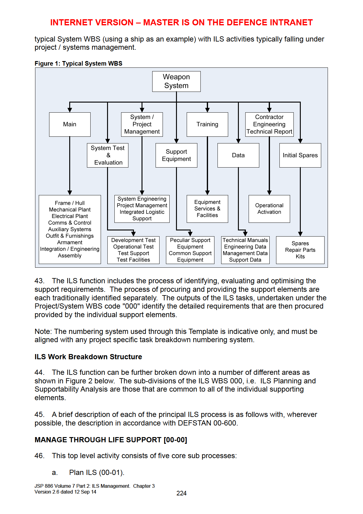
224
JSP 886 DEFENCE LOGISTICS SUPPORT CHAIN MANUAL VOLUME 7 SUPPORT ENGINEERING PART 8.05 TECHNICAL DOCUMENTATION
 JSP 886 DEFENCE LOGISTICS SUPPORT CHAIN MANUAL VOLUME 7 SUPPORT ENGINEERING PART 8.05 TECHNICAL DOCUMENTATION THE MASTER VERSION OF JSP 886 IS PUBLISHED ON THE DEFENCE INTRANET. FOR TECHNICAL REASONS,
How To Support Software Support
 JSP 886 DEFENCE LOGISTICS SUPPORT CHAIN MANUAL VOLUME 7 INTEGRATED LOGISTICS SUPPORT PART 4 SOFTWARE SUPPORT THE MASTER VERSION OF JSP 886 IS PUBLISHED ON THE DEFENCE INTRANET. FOR TECHNICAL REASONS, EXTERNAL
JSP 886 DEFENCE LOGISTIC SUPPORT CHAIN MANUAL VOLUME 7 INTEGRATED LOGISTIC SUPPORT PART 8.12 CONFIGURATION MANAGEMENT
 JSP 886 DEFENCE LOGISTIC SUPPORT CHAIN MANUAL VOLUME 7 INTEGRATED LOGISTIC SUPPORT PART 8.12 CONFIGURATION MANAGEMENT THE MASTER VERSION OF JSP 886 IS PUBLISHED ON THE DEFENCE INTRANET. FOR TECHNICAL REASONS,
JSP 886 THE DEFENCE LOGISTIC SUPPORT CHAIN MANUAL VOLUME 7 INTEGRATED LOGISTICS SUPPORT PART 8.11 QUALITY MANAGEMENT
 JSP 886 THE DEFENCE LOGISTIC SUPPORT CHAIN MANUAL VOLUME 7 INTEGRATED LOGISTICS SUPPORT PART 8.11 QUALITY MANAGEMENT THE MASTER VERSION OF JSP 886 IS PUBLISHED ON THE DEFENCE INTRANET. FOR TECHNICAL REASONS,
JSP 886 THE DEFENCE LOGISTICS SUPPORT CHAIN MANUAL VOLUME 3 SUPPLY CHAIN MANAGEMENT PART 11 LOGISTIC INFORMATION SYSTEMS DATA MANAGEMENT
 JSP 886 THE DEFENCE LOGISTICS SUPPORT CHAIN MANUAL VOLUME 3 SUPPLY CHAIN MANAGEMENT PART 11 LOGISTIC INFORMATION SYSTEMS DATA MANAGEMENT THE MASTER VERSION OF JSP 886 IS PUBLISHED ON THE DEFENCE INTRANET.
Network Rail Infrastructure Projects Joint Relationship Management Plan
 Network Rail Infrastructure Projects Joint Relationship Management Plan Project Title Project Number [ ] [ ] Revision: Date: Description: Author [ ] Approved on behalf of Network Rail Approved on behalf
JSP 886 THE DEFENCE LOGISTIC SUPPORT CHAIN MANUAL VOLUME 2 INVENTORY MANAGEMENT PART 9 THE MANAGEMENT OF ASSETS
 JSP 886 THE DEFENCE LOGISTIC SUPPORT CHAIN MANUAL VOLUME 2 INVENTORY MANAGEMENT PART 9 THE MANAGEMENT OF ASSETS THE MASTER VERSION OF JSP 886 IS PUBLISHED ON THE DEFENCE INTRANET. FOR TECHNICAL REASONS,
IT Project: System Implementation Project Template Description
 2929 Campus Drive Suite 250 IT Project: System Implementation Project Template Description Table of Contents Introduction... 2 Project Phases... 3 Initiation & Requirements Gathering Milestone... 3 Initiation
TEC Capital Asset Management Standard January 2011
 TEC Capital Asset Management Standard January 2011 TEC Capital Asset Management Standard Tertiary Education Commission January 2011 0 Table of contents Introduction 2 Capital Asset Management 3 Defining
AIPM PROFESSIONAL COMPETENCY STANDARDS FOR PROJECT MANAGEMENT PART B CERTIFIED PRACTISING PROJECT PRACTITIONER (CPPP)
") AIPM PROFESSIONAL COMPETENCY STANDARDS FOR PROJECT MANAGEMENT PART B CERTIFIED PRACTISING PROJECT PRACTITIONER (CPPP) Copyright: Australian Institute of Project Management Document Information Document
AIPM PROFESSIONAL COMPETENCY STANDARDS FOR PROJECT MANAGEMENT PART B CERTIFIED PRACTISING PROJECT PRACTITIONER (CPPP) Copyright: Australian Institute of Project Management Document Information Document
In-Service Design Changes
 UNCONTROLLED COPY WHEN PRINTED Regulatory Article 5312 RA 5312 In-Service Design Changes Rationale Following the introduction of an aircraft type into Service use it may be necessary to incorporate design
CHAPTER 49 RELIABILITY & MAINTAINABILITY (R&M) PLANS & PROGRAMMES CONTENT
 PLANS & PROGRAMMES CONTENT") CHAPTER 49 RELIABILITY & MAINTAINABILITY (R&M) PLANS & PROGRAMMES CONTENT Page 1 Introduction 2 2 Background 2 3 The importance of R&M Plans and Programmes 2 4 Similarities and differences between R&M
CHAPTER 49 RELIABILITY & MAINTAINABILITY (R&M) PLANS & PROGRAMMES CONTENT Page 1 Introduction 2 2 Background 2 3 The importance of R&M Plans and Programmes 2 4 Similarities and differences between R&M
Introduction to the ITS Project Management Methodology
 Introduction to the ITS Project Management Methodology In September 1999 the Joint Legislative Committee on Performance Evaluation and Expenditure Review (PEER) produced a report entitled Major Computer
General Notes Time allowed 1 hour. Answer all 60 multiple choice questions Use the proforma answer sheet provided.
 Introductory Certificate The APM Project Fundamentals Qualification. Examination paper Candidate Number Date Location Examination Paper Sample Paper v1.4 General Notes Time allowed 1 hour. Answer all 60
PROJECT MANAGEMENT FRAMEWORK
 PROJECT MANAGEMENT FRAMEWORK DOCUMENT INFORMATION DOCUMENT TYPE: DOCUMENT STATUS: POLICY OWNER POSITION: INTERNAL COMMITTEE ENDORSEMENT: APPROVED BY: Strategic document Approved Executive Assistant to
JSP 886 DEFENCE LOGISTIC SUPPORT CHAIN MANUAL VOLUME 2 INVENTORY MANAGEMENT PART 8 LEARNING AND DEVELOPMENT TO SUPPORT INVENTORY MANAGEMENT
 JSP 886 DEFENCE LOGISTIC SUPPORT CHAIN MANUAL VOLUME 2 INVENTORY MANAGEMENT PART 8 LEARNING AND DEVELOPMENT TO SUPPORT INVENTORY MANAGEMENT THE MASTER VERSION OF JSP 886 IS PUBLISHED ON THE DEFENCE INTRANET.
Develop Project Charter. Develop Project Management Plan
 Develop Charter Develop Charter is the process of developing documentation that formally authorizes a project or a phase. The documentation includes initial requirements that satisfy stakeholder needs
Program Lifecycle Methodology Version 1.7
 Version 1.7 March 30, 2011 REVISION HISTORY VERSION NO. DATE DESCRIPTION AUTHOR 1.0 Initial Draft Hkelley 1.2 10/22/08 Updated with feedback Hkelley 1.3 1/7/2009 Copy edited Kevans 1.4 4/22/2010 Updated
JSP 886 DEFENCE LOGISTICS SUPPORT CHAIN MANUAL VOLUME 2 INVENTORY MANAGEMENT PART 2 PROJECT TEAM INVENTORY PLANNING
 JSP 886 DEFENCE LOGISTICS SUPPORT CHAIN MANUAL VOLUME 2 INVENTORY MANAGEMENT PART 2 PROJECT TEAM INVENTORY PLANNING THE MASTER VERSION OF JSP 886 IS PUBLISHED ON THE DEFENCE INTRANET. FOR TECHNICAL REASONS,
PORTFOLIO, PROGRAMME & PROJECT MANAGEMENT MATURITY MODEL (P3M3)
") PORTFOLIO, PROGRAMME & PROJECT MANAGEMENT MATURITY MODEL (P3M3) 1st February 2006 Version 1.0 1 P3M3 Version 1.0 The OGC logo is a Registered Trade Mark of the Office of Government Commerce This is a Value
PORTFOLIO, PROGRAMME & PROJECT MANAGEMENT MATURITY MODEL (P3M3) 1st February 2006 Version 1.0 1 P3M3 Version 1.0 The OGC logo is a Registered Trade Mark of the Office of Government Commerce This is a Value
PROJECT MANAGEMENT PLAN TEMPLATE < PROJECT NAME >
 PROJECT MANAGEMENT PLAN TEMPLATE < PROJECT NAME > Date of Issue: < date > Document Revision #: < version # > Project Manager: < name > Project Management Plan < Insert Project Name > Revision History Name
Contents. viii. 4 Service Design processes 57. List of figures. List of tables. OGC s foreword. Chief Architect s foreword. Preface.
 iii Contents List of figures List of tables OGC s foreword Chief Architect s foreword Preface Acknowledgements v vii viii 1 Introduction 1 1.1 Overview 4 1.2 Context 4 1.3 Purpose 8 1.4 Usage 8 2 Management
DEFENCE INSTRUCTIONS (GENERAL)
") DEFENCE INSTRUCTIONS (GENERAL) New instruction 0 LOG 4 5 012 Regulation of technical integrity of Australian Defence Force materiel Department of Defence CANBERRA ACT 2600 10 September 2010 Issued with
DEFENCE INSTRUCTIONS (GENERAL) New instruction 0 LOG 4 5 012 Regulation of technical integrity of Australian Defence Force materiel Department of Defence CANBERRA ACT 2600 10 September 2010 Issued with
Delivering progress towards meeting HMG targets on the SME growth agenda
 Delivering progress towards meeting HMG targets on the SME growth agenda Action Plan Version 1.1 dated 16 th August 2013 Author: Robert Astall, Head of Commercial Profession and Capability Background The
Technology management in warship acquisition
 management in warship acquisition A J Shanks B.Eng(Hons) MIET BMT Defence Services Limited SYNOPSIS Today s warship designers and engineers look to technology to provide warships and systems better, cheaper
Do not open this paper until instructed by the invigilator. Please note: This question paper must not be removed from the examination room.
 APM Introductory Certificate in Project Management Exam paper Candidate Reference Number Date of Exam Location of the Exam General Notes Time allowed 1 hour Answer all 60 multiple choice questions Use
The Asset Management Landscape
 The Asset Management Landscape ISBN 978-0-9871799-1-3 Issued November 2011 www.gfmam.org The Asset Management Landscape www.gfmam.org ISBN 978-0-9871799-1-3 Published November 2011 This version replaces
UNCLASSIFIED UNCONTROLLED-IF-PRINTED. Public
 Defence Security Manual DSM Part 2:41 Security for Projects and Capability Planning Version 3 ation date July 2015 Amendment list 24 Optimised for Screen; Print; Screen Reader Releasable to Compliance
Project Management Guidebook
 METHOD 12 3 empowering managers to succeed Project Management Guidebook ISBN 0-473-10445-8 A bout this e-book This e-book was created by Method123 (see www.method123.com) to help provide you with a simple
Your Software Quality is Our Business. INDEPENDENT VERIFICATION AND VALIDATION (IV&V) WHITE PAPER Prepared by Adnet, Inc.
 WHITE PAPER Prepared by Adnet, Inc.") INDEPENDENT VERIFICATION AND VALIDATION (IV&V) WHITE PAPER Prepared by Adnet, Inc. February 2013 1 Executive Summary Adnet is pleased to provide this white paper, describing our approach to performing
INDEPENDENT VERIFICATION AND VALIDATION (IV&V) WHITE PAPER Prepared by Adnet, Inc. February 2013 1 Executive Summary Adnet is pleased to provide this white paper, describing our approach to performing
Step by Step Project Planning
 Step by Step Project Planning Contents Introduction The Planning Process 1 Create a Project Plan...1 Create a Resource Plan...1 Create a Financial Plan...1 Create a Quality Plan...2 Create a Risk Plan...2
A GOOD PRACTICE GUIDE FOR EMPLOYERS
 MITIGATING SECURITY RISK IN THE NATIONAL INFRASTRUCTURE SUPPLY CHAIN A GOOD PRACTICE GUIDE FOR EMPLOYERS April 2015 Disclaimer: Reference to any specific commercial product, process or service by trade
3SL. Requirements Definition and Management Using Cradle
 3SL Requirements Definition and Management Using Cradle November 2014 1 1 Introduction This white paper describes Requirements Definition and Management activities for system/product development and modification
RIBA Plan of Work 2013: Consultation document. You are invited to complete the online questionnaire by 12 August 2012.
 RIBA Plan of Work 2013: Consultation document The RIBA is undertaking a comprehensive review of the RIBA Plan of Work. This document sets out the reasons and the rationale behind that review as well as
Department of Administration Portfolio Management System 1.3 June 30, 2010
 E 06/ 30/ 2010 EX AM PL 1. 3 06/ 28/ 2010 06/ 24/ 2010 06/ 23/ 2010 06/ 15/ 2010 06/ 18/ 2010 Portfolio System 1.3 June 30, 2010 Contents Section 1. Project Overview... 1 1.1 Project Description... 1 1.2
UNSOLICITED PROPOSALS
 UNSOLICITED PROPOSALS GUIDE FOR SUBMISSION AND ASSESSMENT January 2012 CONTENTS 1 PREMIER S STATEMENT 3 2 INTRODUCTION 3 3 GUIDING PRINCIPLES 5 3.1 OPTIMISE OUTCOMES 5 3.2 ASSESSMENT CRITERIA 5 3.3 PROBITY
Operations. Group Standard. Business Operations process forms the core of all our business activities
 Standard Operations Business Operations process forms the core of all our business activities SMS-GS-O1 Operations December 2014 v1.1 Serco Public Document Details Document Details erence SMS GS-O1: Operations
Input, Output and Tools of all Processes
 1 CIS12-3 IT Project Management Input, Output and Tools of all Processes Marc Conrad D104 (Park Square Building) Marc.Conrad@luton.ac.uk 26/02/2013 18:22:06 Marc Conrad - University of Luton 1 2 Mgmt /
Resource Management. Determining and managing the people resources on projects can be complex as:
 Baseline Resource Management RESOURCE MANAGEMENT Purpose To provide a procedure and associated guidelines to facilitate the management of project people resources. Overview This Phase is used to establish
Retained Fire Fighters Union. Introduction to PRINCE2 Project Management
 Retained Fire Fighters Union Introduction to PRINCE2 Project Management PRINCE2 PRINCE stands for: PRojects IN Controlled Environments and is a structured method which can be applied to any size or type
HHS OCIO Policy for Information Technology (IT) Enterprise Performance Life Cycle (EPLC)
 Enterprise Performance Life Cycle (EPLC)") Office of the Chief Information Officer Office of the Assistant Secretary for Resources and Technology Department of Health and Human Services HHS OCIO Policy for Information Technology (IT) Enterprise
Office of the Chief Information Officer Office of the Assistant Secretary for Resources and Technology Department of Health and Human Services HHS OCIO Policy for Information Technology (IT) Enterprise
ITIL 2011 Lifecycle Roles and Responsibilities UXC Consulting
 ITIL 2011 Lifecycle Roles and Responsibilities UXC Consulting Date November 2011 Company UXC Consulting Version Version 1.5 Contact info@uxcconsulting.com.au http://www.uxcconsulting.com.au This summary
2.1 STAGE 1 PROJECT PROCUREMENT STRATEGY
 APM Procurement Guide : Draft7_RevA_Chapter 2.1_Project Procurement Strategy_Jan12 1 2.1 STAGE 1 PROJECT PROCUREMENT STRATEGY In this stage, the project definition is developed so that decisions can be
Delivery Management Guidelines Delivery Process 2 - Project Management
 Delivery Management Guidelines Delivery Process 2 - Project Management Version control Version 9-1 Date 2010-10-18 Status Approved The IDMS Prov Infr Strat DP1: Portfolio Management DP1-1 Infrastructure
Procurement Policy. Finance Policy
 1 Purpose Victoria University of Wellington (the University ) and its subsidiaries are large scale procurers of goods and services. To ensure continued accountability and robust governance, it is critical
PROJECT MANAGEMENT METHODOLOGY SECTION 3 -- PLANNING PHASE
 PROJECT MANAGEMENT METHODOLOGY SECTION 3 -- PLANNING PHASE Table of Contents Introduction...3-1 Overview...3-1 The Process and the Project Plan...3-1 Project Objectives and Scope...3-1 Work Breakdown Structure...3-1
Department of the Environment and Local Government. Project Management. Public Private Partnership Guidance Note 7. 14 April 2000
 Project Management Project Management Public Private Partnership Guidance Note 7 14 April 2000 Guidance Note 7 14 April 2000 Project Management Contents Section Page I INTRODUCTION...1 SCOPE AND PURPOSE
U.S. Department of Education Federal Student Aid
 U.S. Department of Education Federal Student Aid Lifecycle Management Methodology Stage Gate Review Process Description Version 1.3 06/30/2015 Final DOCUMENT NUMBER: FSA_TOQA_PROC_STGRW.NA_001 Lifecycle
Aligning CMMI & ITIL. Where Am I and Which Way Do I Go? 2006 - cognence, inc.
 Aligning CMMI & ITIL Where Am I and Which Way Do I Go? 2006 - cognence, inc. Agenda Where Am I? Current Situation Process Improvement Objectives How Do I Get There? CMMI ITIL Mapping, Commonalities, Differences
System/Data Requirements Definition Analysis and Design
 EXECUTIVE SUMMARY This document provides an overview of the Systems Development Life-Cycle (SDLC) process of the U.S. House of Representatives. The SDLC process consists of seven tailored phases that help
Manag. Roles. Novemb. ber 20122
 Information Technology Manag gement Framework Roles and Respo onsibilities Version 1.2 Novemb ber 20122 ITM Roles and Version History Version ed By Revision Date Approved By Approval Date Description of
Project Management Office (PMO)
") Contents I. Overview of Project Management...4 1. Project Management Guide (PMG)...4 1.1 Introduction...4 1.2 Scope...6 1.3 Project Types...6 2. Document Overview, Tailoring, and Guidance...7 3. The Project
Contents I. Overview of Project Management...4 1. Project Management Guide (PMG)...4 1.1 Introduction...4 1.2 Scope...6 1.3 Project Types...6 2. Document Overview, Tailoring, and Guidance...7 3. The Project
MANAGE INDUSTRIAL CONTROL SYSTEMS LIFECYCLE
 SECURITY FOR INDUSTRIAL CONTROL SYSTEMS MANAGE INDUSTRIAL CONTROL SYSTEMS LIFECYCLE A GOOD PRACTICE GUIDE Disclaimer Reference to any specific commercial product, process or service by trade name, trademark,
APPENDIX A (CFO/263/09) Merseyside Fire & Rescue Service ICT Outsourcing Procurement Support. Final Report
 Merseyside Fire & Rescue Service ICT Outsourcing Procurement Support. Final Report") Merseyside Fire & Rescue Service ICT Outsourcing Procurement Support Final Report Version 1.1 Oct 2009 Contents 1. Executive Summary...3 2. Context and Background...3 3. Deliverables and Value Added...
Merseyside Fire & Rescue Service ICT Outsourcing Procurement Support Final Report Version 1.1 Oct 2009 Contents 1. Executive Summary...3 2. Context and Background...3 3. Deliverables and Value Added...
TEST, EVALUATION & ACCEPTANCE BEST PRACTICE. Executive Summary
 WHITE PAPER: TEST, EVALUATION & ACCEPTANCE BEST PRACTICE BMT s experience of UOR Capability Delivery Executive Summary BMT Defence Services (BMT) has provided support to the UK MoD (primarily DE&S) for
Project Management Standards: A Review of Certifications/Certificates
 Project Standards: A Review of Certifications/Certificates Standards for Project Supporting Certification and Certificates Certificate Certification The Project Body of Knowledge PMBOK Guide Projects in
DRAFT PLANNING THE OPENING OF A ROAD PROJECT GUIDELINE 1
 DRAFT PLANNING THE OPENING OF A ROAD PROJECT GUIDELINE 1 Guideline: DRAFT Planning the opening of a road project guideline Version: 1.1 Issue: September 2009 Approved By: Phil Margison General Manager,
Digital Continuity in ICT Services Procurement and Contract Management
 Digital Continuity in ICT Services Procurement and Contract Management This guidance relates to: Stage 1: Plan for action Stage 2: Define your digital continuity requirements Stage 3: Assess and manage
UoD IT Job Description
 UoD IT Job Description Role: Projects Portfolio Manager HERA Grade: 8 Responsible to: Director of IT Accountable for: Day to day leadership of team members and assigned workload Key Relationships: Management
Employer s Information Requirements Version 07 28.02.13. Core Content and Guidance Notes
 Employer s Information Requirements Version 07 28.02.13 Core Content and Guidance Notes Employer s Information Requirements - Guidance notes version 07: 28.02.13 Contents 1.0 Employer s Information Requirements
BEST PRACTICE GUIDE 6: ESTABLISHING CONTRACTS. RDTL MINISTRY OF FINANCE Procurement Service
 RDTL MINISTRY OF FINANCE Procurement Service BEST PRACTICE GUIDE 6: ESTABLISHING CONTRACTS 1 RDTL Procurement Guidelines The Procurement Legal Regime Decree Law sets out new procurement processes which
Wharton Construction Ltd. Quality Manual. Kellaw Road Yarm Road Business Park Darlington DL1 4YA
 Quality Manual Kellaw Road Yarm Road Business Park Darlington DL1 4YA MANUAL IDENTIFICATION This document is a controlled/uncontrolled copy. Copy Number:...of... Issued to... Title... Holders of controlled
Integrating Project Management and Service Management
 Integrating Project and Integrating Project and By Reg Lo with contributions from Michael Robinson. 1 Introduction Project has become a well recognized management discipline within IT. is also becoming
REQUEST FOR EXPRESSIONS OF INTEREST (CONSULTANT SERVICES)
") REQUEST FOR EXPRESSIONS OF INTEREST (CONSULTANT SERVICES) Consultancy services for Systems Integration and IT project management Client: Central Bank of Yemen Country: Republic of Yemen Project: Financial
REQUEST FOR EXPRESSIONS OF INTEREST (CONSULTANT SERVICES) Consultancy services for Systems Integration and IT project management Client: Central Bank of Yemen Country: Republic of Yemen Project: Financial
NUMBER 107-004-030 PO EFFECTIVE DATE. July 1, 2015 REFERENCE/AUTHORITY. Procedure: 107-004-030 PR APPROVED SIGNATURE
 STATEWIDE POLICY DIVISION NUMBER 107-004-030 PO EFFECTIVE DATE July 1, 2015 REFERENCE/AUTHORITY SUPERSEDES Policy #107-004-030 Feb. 1, 2004 PAGE NUMBER Pages 1 of 7 Chief Information Office POLICY OWNER
PHASE 3: PLANNING PHASE
 PHASE 3: PLANNING PHASE The Planning Phase focuses principally on required project planning work. Proper comprehensive project planning is essential to a successful IT project, and incomplete project planning
A COMPARISON OF PRINCE2 AGAINST PMBOK
 Introduction This comparison takes each part of the PMBOK and gives an opinion on what match there is with elements of the PRINCE2 method. It can be used in any discussion of the respective merits of the
Superseded by T MU AM 04001 PL v2.0
 Plan T MU AM 04001 PL TfNSW Configuration Management Plan Important Warning This document is one of a set of standards developed solely and specifically for use on the rail network owned or managed by
Office for Nuclear Regulation
 ONR GUIDE LC17 Management Systems Document Type: ONR Nuclear Safety Technical Inspection Guide Unique Document ID and Revision No: NS-INSP-GD-017 Revision 2 Date Issued: November 2012 Review Date: November
Procurement Capability Standards
 IPAA PROFESSIONAL CAPABILITIES PROJECT Procurement Capability Standards Definition Professional Role Procurement is the process of acquiring goods and/or services. It can include: identifying a procurement
An example ITIL -based model for effective Service Integration and Management. Kevin Holland. AXELOS.com
 An example ITIL -based model for effective Service Integration and Management Kevin Holland AXELOS.com White Paper April 2015 Contents Introduction to Service Integration and Management 4 An example SIAM
Appendix E Program Management Plan Template
 Appendix E Program Management Plan Template Version 2 March 7, 2005 This page is intentionally left blank. Version 2 March 7, 2005 Title Page Document Control Panel Table of Contents List of Acronyms Definitions
The Transport Business Cases
 Do not remove this if sending to pagerunnerr Page Title The Transport Business Cases January 2013 1 Contents Introduction... 3 1. The Transport Business Case... 4 Phase One preparing the Strategic Business
MANAGING DIGITAL CONTINUITY
 MANAGING DIGITAL CONTINUITY Project Name Digital Continuity Project DRAFT FOR CONSULTATION Date: November 2009 Page 1 of 56 Contents Introduction... 4 What is this Guidance about?... 4 Who is this guidance
1. Evolution of infrastructure procurement in NSW. 2. Market consultation and outcomes. 3. Response and implementation. 4. Project Deed Evolution
 Reducing Bid Costs for Outcome-Based Procurements in NSW Infrastructure and Structured Finance Unit: Partnering to Create Partnerships December 2015 1. Evolution of infrastructure procurement in NSW 2.
The overall aim for this project is To improve the way that the University currently manages its research publications data
 Project Plan Overview of Project 1. Background The I-WIRE project will develop a workflow and toolset, integrated into a portal environment, for the submission, indexing, and re-purposing of research outputs
PPM V2.0 Frequently Asked Questions (FAQs) U.S. Department of Housing and Urban Development
 U.S. Department of Housing and Urban Development") PPM V2.0 Frequently Asked Questions (FAQs) U.S. Department of Housing and Urban Development December 2015 1. Getting Started with PPM Life Cycle 2. PPM Life Cycle Process 3. PPM V2.0 and Project Types
PPM V2.0 Frequently Asked Questions (FAQs) U.S. Department of Housing and Urban Development December 2015 1. Getting Started with PPM Life Cycle 2. PPM Life Cycle Process 3. PPM V2.0 and Project Types
WHITE PAPER IT SERVICE MANAGEMENT IT SERVICE DESIGN 101
 WHITE PAPER IT SERVICE MANAGEMENT IT SERVICE DESIGN 101 Prepared by: Phillip Bailey, Service Management Consultant Steve Ingall, Head of Service Management Consultancy 60 Lombard Street London EC3V 9EA
ISEB MANAGER S CERTIFICATE IN ITIL INFRASTRUCTURE MANAGEMENT. Guidelines for candidates who are taking the ICT Infrastructure Examination
 ISEB MANAGER S CERTIFICATE IN ITIL INFRASTRUCTURE MANAGEMENT Guidelines for candidates who are taking the ICT Infrastructure Examination This qualification is based on ITIL Infrastructure Management as
Project Execution Guidelines for SESAR 2020 Exploratory Research
 Project Execution Guidelines for SESAR 2020 Exploratory Research 04 June 2015 Edition 01.01.00 This document aims at providing guidance to consortia members on the way they are expected to fulfil the project
The Asset Management Landscape
 The Asset Management Landscape Second Edition ISBN 978-0-9871799-2-0 Published March 2014 www.gfmam.org The Global Forum on Maintenance and Asset Management The Global Forum on Maintenance and Asset Management
Contract Template Selection and Tailoring Guide
 Contract Template Selection and Tailoring Guide Version 2.0 January 2015 Note to Defence Staff and External Agencies Defence staff and external agencies intending to use the associated Australian Standard
Project Management Handbook 2014. "To Understand the Causes of Things"
 Management Handbook 2014 "To Understand the Causes of Things" AMENDMENT RECORD This document has been issued and amended as follows: - Isu. Rev. Reason for Issue / revision Date Issued to Team Stakeholders
8. Master Test Plan (MTP)
") 8. Master Test Plan (MTP) The purpose of the Master Test Plan (MTP) is to provide an overall test planning and test management document for multiple levels of test (either within one project or across
8. Master Test Plan (MTP) The purpose of the Master Test Plan (MTP) is to provide an overall test planning and test management document for multiple levels of test (either within one project or across
Project Management Plan for
 Project Management Plan for [Project ID] Prepared by: Date: [Name], Project Manager Approved by: Date: [Name], Project Sponsor Approved by: Date: [Name], Executive Manager Table of Contents Project Summary...
IRIS International Railway Industry Standard
 English Addendum, 19th June 2008 IRIS International Railway Industry Standard Hier kann ein kleiner Text stehen Hier kann ein kleiner Text stehen Hier kann ein kleiner Text stehen Chapter 1 3 IRIS Certification
PHASE 3: PLANNING PHASE
 PHASE 3: PLANNING PHASE The ning Phase focuses principally on required project planning work. Proper comprehensive project planning is essential to a successful IT project, and incomplete project planning
Project Management Guidelines
 Project Management Guidelines 1. INTRODUCTION. This Appendix (Project Management Guidelines) sets forth the detailed Project Management Guidelines. 2. PROJECT MANAGEMENT PLAN POLICY AND GUIDELINES OVERVIEW.
White Paper. PPP Governance
 PPP Governance The Governance of Projects, Programs and Portfolios (PPP) (sometimes called project governance for convenience) is the sub-set of corporate and organisational governance 1 focused on assisting
OPERATIONAL PROJECT MANAGEMENT (USING MS PROJECT)
") OPERATIONAL PROJECT MANAGEMENT (USING MS PROJECT) 3 DAY COURSE INTRODUCTION The principles of project management are generic and therefore can be applied to all projects regardless of business sector.
OPERATIONAL PROJECT MANAGEMENT (USING MS PROJECT) 3 DAY COURSE INTRODUCTION The principles of project management are generic and therefore can be applied to all projects regardless of business sector.
NASCIO EA Development Tool-Kit Solution Architecture. Version 3.0
 NASCIO EA Development Tool-Kit Solution Architecture Version 3.0 October 2004 TABLE OF CONTENTS SOLUTION ARCHITECTURE...1 Introduction...1 Benefits...3 Link to Implementation Planning...4 Definitions...5
Gateway review guidebook. for project owners and review teams
 Gateway review guidebook for project owners and review teams The State of Queensland (Queensland Treasury and Trade) 2013. First published by the Queensland Government, Department of Infrastructure and
Appendix 2-A. Application and System Development Requirements
 Appendix 2-A. Application and System Development Requirements Introduction AHRQ has set up a Distributed Systems Engineering Lab (DSEL) to support all internal development efforts and provide a facility
SOFTWARE ASSURANCE STANDARD
 NOT MEASUREMENT SENSITIVE National Aeronautics and NASA-STD-8739.8 w/change 1 Space Administration July 28, 2004 SOFTWARE ASSURANCE STANDARD NASA TECHNICAL STANDARD REPLACES NASA-STD-2201-93 DATED NOVEMBER
Software Quality Subcontractor Survey Questionnaire INSTRUCTIONS FOR PURCHASE ORDER ATTACHMENT Q-201
 PURCHASE ORDER ATTACHMENT Q-201A Software Quality Subcontractor Survey Questionnaire INSTRUCTIONS FOR PURCHASE ORDER ATTACHMENT Q-201 1. A qualified employee shall be selected by the Software Quality Manager
University of Brighton Sustainable Procurement Strategy 2011-2015
 University of Brighton Sustainable Procurement Strategy 2011-2015 Sustainable procurement in a challenging environment Introduction There is widespread recognition that climate change and the use of dwindling
TfNSW Standard Requirements TSR T Technical Management
 Template Applicable to: Transport Projects Quality Management System Status: Division: Approved Transport Projects Version: 5.0 Desksite No.: 3455797_1 Date of issue: 1 July 2014 Effective date: 1 July
JOURNAL OF OBJECT TECHNOLOGY
 JOURNAL OF OBJECT TECHNOLOGY Online at www.jot.fm. Published by ETH Zurich, Chair of Software Engineering JOT, 2006 Vol. 5. No. 8, November-December 2006 Requirements Engineering Tasks Donald Firesmith,
POSITION DESCRIPTION
 POSITION DESCRIPTION Position Title: Reports to: DEVICES CATEGORY MANAGER MANAGER, DEVICES FUNDING Date: September 2014 PHARMAC S MISSION Our legislative objective is: to secure for eligible people in
COMMONWEALTH OF VIRGINIA
 COMMONWEALTH OF VIRGINIA Information Technology Resource Management (ITRM) TECHNOLOGY MANAGEMENT PROJECT MANAGEMENT STANDARD Virginia Information Technologies Agency (VITA) Reviews This publication was