Automotive Computer System Diagnostics ebook
|
|
|
- Ralf Cameron
- 8 years ago
- Views:
Transcription
1 Table of Contents Automotive Computer System Diagnostics... 2 Introduction... 2 Getting Started... 3 Sync Zones... 5 Cables and Adapters... 5 Led Display... 7 Storage CompactFlash (CF) Cards... 8 Getting Power to the Scanner... 8 Programming for the Vehicle... 9 The Simulated Scanner... 9 Loading the Scanner Software Demonstration Program Entering the VIN into the Scanner Screen Layout and Navigation The Main Menu Tool Help Setup Setting the Date and Time Saved Data System Testing Codes & Data and Road Test N Key Action and Exit Menu Recording and Reviewing Movies Clear Codes Graphing Mode Holding and Releasing a Parameter in Graphing Mode Viewing and Comparing Graphed Parameters Functional Tests Information Tests Variable Control Tests Custom Setup English/Metric Troubleshooter Using the Troubleshooter Code Tips Symptom Tips Technical Assistance Fast-Track Data Scan (Normal Values) Onboard Diagnostics and OBD-II Data Link Connector Generic OBD-II and Global OBD-II O2 MONITORS (OBD-II) Freeze Frame Troubleshooter Global OBD-II... 55

2 Automotive Computer System Diagnostics Introduction As the number and complexity of computers and electronic systems on late model vehicles has continued to increase, diagnostic methods have become more sophisticated. Scan tools, DVOMs, and graphing tools have become essential to diagnostics. With OBD-II compliant vehicles, a scan tool is necessary to read and/or clear trouble codes from the PCM; however, if a technician is using his expensive scan tool just to read and clear codes, he is missing some very important and helpful benefits that most scan tools feature. Certainly, today's scan tools will read and clear codes, but many can also exercise several of the onboard computer outputs, and toggle components on and off, as well as take a "snapshot" or "movie" of the computer data stream. The benefit of this becomes evident when trying to diagnose intermittent problems. The SOLUS Scanner This course will focus on the operation of the Snap-on SOLUS Scanner in diagnosing computerized vehicles. The SOLUS is the next generation in the family of Snap-on scanners. Its operation is much the same as the MT2500 or the MTG2500, and like the MTG2500, the SOLUS includes the option of permitting the user to select and graph live data parameters on the display. Using the Snap-on Vehicle Communication and Fast Track Troubleshooter software, the SOLUS provides you with extensive vehicle-specific engine, transmission, antilock brake system (ABS) and airbag trouble codes, selected functional tests, and troubleshooting information. Also, a great deal of software is integrated into a single component, a CompactFlash card, eliminating the need to switch software cartridges when testing vehicles from different manufacturers (most applications). The advantage of having a graphic display of parameter data is that it allows you to quickly spot glitches, dropouts, spikes, and other signal inconsistencies. This comes in handy when conducting a wiggle test or trying to induce symptoms, because it eliminates the need to constantly monitor the screen while watching for parameter values to change. You can work with both hands with only an occasional glance at the screen to see if a graph pattern has changed. Another advantage of having a graphic display is that it allows you to quickly compare the activity of two or more parameter signals to see if they are synchronized or if they both respond correctly to changes in operating conditions (for example, comparing the crankshaft position sensor to the camshaft position senor signal). The graphing function has other useful features as well, which we will discuss in detail. Page 2 of 56

3 Like the earlier scanners, the SOLUS is organized and operated by menus. To use the scanner, you simply scroll though menus and enter desired selections. If the scanner does not automatically identify the connected vehicle, you input selected VIN characters to ID the vehicle to the scanner, and then choose tests or displays in order to troubleshoot the vehicle. The scanner follows programmed routines and can provide complete messages and tips, trouble codes and definitions, graphs, and data readouts. The screen prompts you along the way, asking for input and offering options. Safety First! Always follow all general safety guidelines for servicing motor vehicles concerning adequate ventilation, working around hot or moving parts, proper use of parking brake, gear selector, wheel blocks, and disabling fuel or ignition systems. Refer to equipment User's Manual and vehicle Service Manual Getting Started Each scan tool brand has features that make it different from the other tools on the market. Learning proper use of the controls is fundamental to understanding the operation and use of the tool. The Snapon SOLUS has just six controls, making it very easy to use. The controls are the Power button, the Thumb Pad, the Y and N keys, the Brightness/Contrast button, and the S button. The top of the SOLUS houses the tool s connection ports and CompactFlash (CF) card slots. The connections include a DC power jack, a USB port, an infrared (IR) output, CF card slots 1 and 2, and the data cable connector. Liquid Crystal Display (LCD) The viewing screen is a 6.2 color crystal display. N (No) and Y (Yes) Buttons N Button The N button is used to do the following: To exit a menu or program To close an open list and return to the previous menu. To answer No when a Yes or No choice is given. To return to the main menu. Y Button The Y button is used to do the following: To select the item you highlighted using the Thumb Pad. To answer Yes when a Yes or No choice is given. Page 3 of 56


4 Thumb Pad The Thumb Pad moves the highlight, allowing vertical and horizontal on-screen movement. The Thumb pad is typically used in combination with the Y and N buttons. Right Handgrip Brightness/Contrast Button The Brightness/Contrast button opens the dialog box that allows you to adjust the screen for optimum viewing. S Button The S button can be customized to perform different functions from the UTILITIES > Tool Setup menu. Power Button The Power Button powers up the SOLUS unit, turns it off, and enables Stand by mode. Left Handgrip DC Power Jack The DC Power Jack can be used to power the unit via an AC adapter. Page 4 of 56

5 USB Port The SOLUS unit has a USB port for connecting to a PC. IR Output The IR output is for printing data. Card Reader CompactFlash Slots 1 and 2. Data Cable Connector The data cable connector is used to connect the SOLUS unit to a vehicle diagnostic connector for testing. Sync Zones This course features a very useful tool called "Sync Zones" that will allow the user to synchronize the simulated scanner with the text in the course. Why are Sync Zones needed? The simulated MT2500 features many of the functions that are available in the actual scanner. A great deal of functionality combined with a curious user could allow the scanner to become out of sync with the course. Although being curious can be a good thing, in web-based training where there is no instructor it could result in a poor learning experience. OK, so how do "Sync Zones" help? Glad you asked. At anytime in the course if you find that the simulated SOLUS does not match the text and example screen shots, simply click on the "Sync Zone" and your problem is solved. Cables and Adapters One of the assets of the SOLUS is its versatility. It has the capability to connect to many different vehicles and provide the technician with needed information to quickly repair the vehicle. All OBDII vehicles (1996 and later) use the standard data cable. Other vehicles may require an adapter. Available cables and adapters for the SOLUS are pictured on this page. Page 5 of 56

6 Page 6 of 56
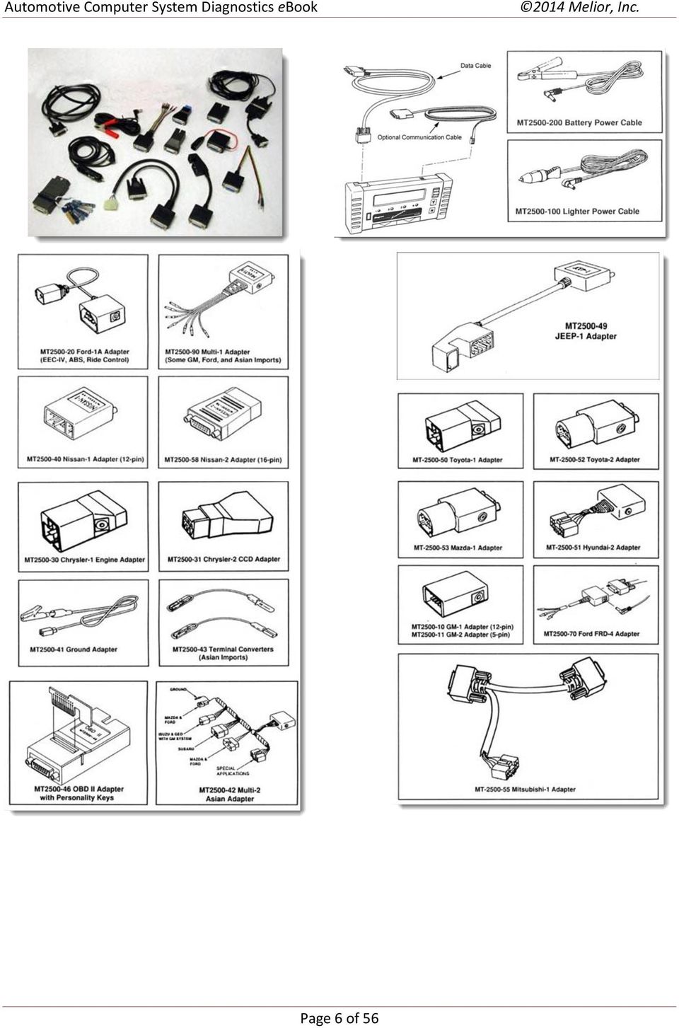


7 You may have to refer to the scanner reference manual or vehicle service manual to locate the proper diagnostic connector on pre-obd-ii models. Ford, in particular, has used several different connectors in different locations. The DLC for the Ford shown here is under the hood on the right side, and requires the standard FORD-1A adapter and two To prevent damage to the scanner or vehicle, refer to the scanner reference manual or vehicle service manual if you are not sure of the DLC. connections. The protective cap has been removed from the connectors. The connected plug is shown in the companion photo. A flat ribbon extension for the data cable is available for under-hood applications, permitting closing the hood for test driving. Do not connect the scanner adapter lead to the tach terminal. Serious damage to the scanner can result. Led Display Those who are familiar with the MT series of scanners may recall that they have a series of four red light-emitting diodes (LEDs) just below the display window. On the SOLUS unit, the "LED"s appear on the display screen, but they function in the same manner as before. The LEDs are programmed to blink when certain ON - OFF situations occur. The LEDs have different assignments for different vehicle manufacturers, and in some cases, you can reprogram assignments for LEDs 3 and 4 to react to different conditions. For instance, LED #1 may be associated with Closed Loop operation (GM engine tests - except diesel). It will light when the system has reached Closed Loop. The next LED (LED #2) may be associated with rich or lean exhaust and will blink on when the exhaust is rich. In most cases the LEDs 1 and 2 are predetermined depending on the vehicle and system being diagnosed. The user can program LEDs 3 and 4 as desired (GM applications). More information about LED programming will be provided later. Page 7 of 56

8 Storage CompactFlash (CF) Cards The SOLUS has two CF card slots. Slot 1 is for the master storage CF card. The master storage CF card contains all of the standard bundled software for the unit, such as Fast-Track Troubleshooter and communication software for domestic and import OEMs, Global OBD, and much more. The Troubleshooter software provides useful tips, including diagnostic procedures and tips, code setting parameters, symptom tips, and functional test tips. Separate cartridges are not necessary with SOLUS, because of the vast amount of data that can be stored on a CF card. European software titles and adapters, and a CAN (Controller Area Network) adapter are also available. User data, such as freeze frame snap shots and movie frames can also be stored on the master storage CF card. Slot 2 is for an optional user data storage CF card. Saving data will be covered later. A master storage CF card must be installed in Slot 1 for the SOLUS unit to operate. Make sure the unit is turned off before installing the master storage CF card in Slot 1. IMPORTANT: Never remove the master storage CF card while the unit is turned on. Doing so will damage the software and prevent the SOLUS unit from operating properly. Getting Power to the Scanner There are three ways to supply power to the SOLUS unit: Connect to vehicle power Install batteries Connect to an AC adapter Connecting to Vehicle Power OBDII vehicles supply 12V vehicle system power to the SOLUS through the Diagnostic Link Connector (DLC), normally located below the dash on the driver's side. The 16 pin OBD-II DLC has 12 volts on pin 16 of the connector, and ground at pins 4 and 5. One end of the data cable is connected to the top of the SOLUS unit and the other end is connected to the vehicle DLC. Power will be supplied with the ignition turned on. Older and non-obdii vehicles may require an additional adapter. Refer to the appropriate Vehicle Communication Software (VCS) manual supplied with the software to determine which adapter to use for the vehicle being tested. For vehicles that do not supply power through the diagnostic connector, you must use the auxiliary power cables supplied with the SOLUS unit. Using the Auxiliary Power Cables Attach one end of the Lighter Power Cable to the test adapter attached to the data cable and the other end to either the cigarette lighter or the Battery Power Cable lighter receiver. Once connected to the Lighter Power Cable, connect the Battery Power Cable to the positive and negative battery terminals of your test vehicle. Page 8 of 56


9 Using Battery Power The SOLUS unit comes with six alkaline AA batteries. The batteries are installed in a slot under the right handgrip. When it becomes necessary to replace the batteries, an alternate power source can be connected to the SOLUS to retain the clock and custom settings. The batteries maintain the time, date, and other custom settings but should not be the primary source of power. Caring For the Scanner Before and after each use, check the housing, wiring, and connectors for dirt and damage. At the end of each working day, clean the housing, wiring, and connectors with a damp cloth. Do not spray liquids directly onto the scanner. Programming for the Vehicle Many vehicles made after 1989 can be automatically identified by the scanner. If this is the case, the scanner will display the VIN and the message "Auto-Identified" will appear on the screen, either when the key is turned on, or after selecting the manufacturer. Other vehicles will have to be entered into the scanner manually for identification. To identify a vehicle to the scanner manually, characters from the car's Vehicle Identification Number must be entered. You must read the VIN in order to identify the vehicle correctly. Don't try to enter the VIN from memory - you'll end up in trouble. The VIN is located on the left side of the dash, and can be read by looking through the windshield. VINs have been standardized somewhat (for instance, the 10th digit represents the year of If the scanner does not auto-identify the manufacture and the 8th digit represents the vehicle, enter the requested VIN characters. engine), but there are still differences among manufacturer code structures. The VIN can provide a wealth of information about a vehicle, such as the type of restraints installed, country of origin, assembly plant, etc. Consult vehicle service manuals for more information. The Simulated Scanner To help users become familiar with the operation of the Snap-on SOLUS, this course uses a simulated scanner. This guide provides the information for using the Simulated Scanner. Log in to the Today s Class web course Automotive Computer Systems Diagnostics. Page 9 of 56

10 To use the Simulated SOLUS scanner visit the Today s Class web course Automotive COmpuer System Diagnostics. Ensure that you have pop-ups enabled in your browser and click on the link on the page The Simulated Scanner to display the simulated SOLUS scanner. You will use this scanner as you proceed through the course so ensure that you do not close the page containing it. If you do, return here to reopen the scanner. At this point you may wish to resize your browser window and the solus scanner window so that you may view the course text and use the scanner at the same time. Depending on how large your screen resolution size is, you may wish to zoom in on the solus scanner (if your browser supports this capability) by holding ctrl and pressing the + key on your keyboard. The scanner simulator you see here is programmed to display many of the functions of the scan tool. The controls function in the same manner as a real SOLUS scanner. As you advance through the course, click on the controls to display the desired options and follow along. An actual scanner can perform many more functions. Menu options and screen displays will vary somewhat, depending on the vehicle make and model, and the scanner software version. You will click on the Y key or the right arrow of the thumb pad image to begin, and then you will follow the sequence of screens, clicking Y or thumb padding as appropriate. Just as with a real scanner, click N to back up (or see Help screens if available). Click on the upper arrow of the thumb pad image to scroll up, and click on the lower portion to scroll down. Loading the Scanner Software The scanner appears powered up here. The "Scanner" selection is the default mode, and the Vehicle Communication menu appears to the right. To begin loading the scanner software, click on the Y key or the right arrow of the thumb pad image. This will highlight "US Domestic," which is the default selection. You can scroll down to select "Asian," European," or "Global OBDII." A menu of available vehicle model years will also appear to the right. From "US Domestic," press Y or thumb pad right to move the highlight to " " This will open another menu window for the Troubleshooter software. Press Y or thumb pad right to highlight "Drivability" and then press Y again to load the software. The startup screen will first briefly display "Component is loading. Please wait," then the display will change to "Initializing Please wait," and finally, "Loading Scanner.. Please wait." After the scanner has loaded, the following screen will appear: The screen shown indicates that the Domestic Primary software is loaded, and that it is software version 6.7. It also shows the loaded Domestic Troubleshooter software is version 3.1. Page 10 of 56

11 Now, you have the option to press the Y key to continue to the next screen, or to press the N key for help. If you choose the N key, it will take you to a set of instructions basic to the operation of the scanner. You may view those screens now. After you view the instructions, press the N key to return to the previous screen. Press the Y key when you are ready to proceed. The next screen appears as follows: Scroll the thumb pad up or down, and the cursor (>>) moves between the possible selections for vehicle manufacturer. Note that two other options are available: New Features, and Generic OBD- II. The Generic OBD-II option allows entry of any OBD-II compliant vehicle, and supplies you with emissions-related data and codes. We will discuss the OBD-II option later. New Features informs you of new information and/or tests that are available with the current version of software installed. You can check the new features of this software version by selecting this option now. Remember to press N to back out of New Features screens and return to the manufacturer selection screen. Demonstration Program A demonstration program for each manufacturer is stored in the memory of Snap-on scanner software CF cards. The demonstration program allows the user to become familiar with the operation of the scanner without actually having to be connected to a vehicle. We will use a GM demo program for the same purpose here. Entry into the demonstration programs may vary among applications. Some demos are available from the main menu for their group, such as the demo for GM. Other demos are accessed by entering a special sequence into the VIN positions when prompted for the vehicle identification. Refer to the VCS manuals supplied with the software for information. Demos are also provided for Troubleshooter software (where applicable) and the Global OBDII mode. Depending upon the software version installed on the scanner, demo program screens and options may differ from the ones you see in this course. Entering the VIN into the Scanner The demonstration software we will use applies to a 1995 Buick with a 3.8L engine. To enter the demonstration, scroll the thumb pad to point to General Motors and press the Y key. This is the same action that you would use when programming a live car. The next screen that appears should look like this: Page 11 of 56
 moves between the possible selections for vehicle manufacturer.")

12 The selections available here are ABS, which allows you to see data and codes related to the Antilock Brake System, and ENGINE AND OTHER SYSTEMS. This option allows entry into the engine management system as well as body, transmission, and air bag systems. ABS, body, transmission, and airbag data are not programmed into the simulated scanner. Scroll the thumb pad up or down until the cursor is pointing to ENGINE AND OTHER SYSTEMS and press the Y key. Now, we begin the programming sequence for the vehicle. You should see a screen that looks this: The first bit of information you are prompted to enter normally identifies the vehicle year (10th VIN digit). To open the pre-programmed demonstration program, a special sequence of characters must be entered into the VIN positions. Scroll the thumb pad up until a "D" appears where the "A" is now. If you were programming a live vehicle, you would find the VIN at the base of the windshield, inside on the driver's side of the dash pad. You would then find the 10th digit and enter the appropriate character. Once you see the "D," press the Y key and you should see the following information on the screen: Note that the scanner correctly displays 1983 as the selected year (D) on the second screen. This will change to the demo vehicle year (1995) when you complete the sequence for the demo program. The scanner next instructs you to enter the 3rd VIN character. The 3rd character normally refers to the division of GM. Scroll the thumb pad up until a "1" appears, and then press the Y key. Next, the scanner asks for the 8th character. The 8th digit refers to the engine. Scroll the thumb pad down until an "M" appears and press the Y key. You should then see the following: Page 12 of 56
.")
13 This screen shows that the scanner has entered the demonstration program, and is displaying a '95 Buick with a 3.8L V6 engine. To finish the programming sequence, the scanner asks on this screen for transmission type, and on the next screen, whether or not the vehicle has air conditioning. For this demonstration, enter Y to both questions. Finally, the scanner displays the vehicle and options selected: If the vehicle information being displayed by the scanner does not exactly match the vehicle you wish to test, press the N key to return to the VIN entry screen and begin again. Please do not try to remember the VIN; it is very important to enter the correct information during this phase to avoid any conflicts or errors, such as "no communication with vehicle." If you make a mistake at any time during the VIN programming sequence, press the N key to re-enter the previous VIN character. If all the information is correctly entered, press the Y key. You should see the following screen: This information specifies which adapter to use to connect the scanner, and where the Diagnostic Link Connector is located on the vehicle. The scanner refers to the DLC on some models as an ALDL (Assembly Line Diagnostic Link). As you can see, data entry for vehicle identification is rather simple. All the user has to do is scroll the thumb pad until the cursor points to the appropriate option or the correct character appears, and then press the Y key to continue. If you are testing a live vehicle, the data cable with the correct adapter must usually be connected to the vehicle to continue past this point. You may see a screen similar to the following: CONNECT GM-1 TO 12-PIN CONNECTOR LOCATED UNDER LEFT SIDE OF DASH. (EXCEPT CONVERSIONS & SPECIAL BUILDS) VEHICLE ID IS STORED. OK TO RELEASE BUTTON The last line of this message refers to the Quick ID button that was used on the MT series scanners. On some older vehicles for which the data has not changed, you may see a message like this, or a reference to the "thumb wheel" rather than the "thumb pad." The Quick ID button is not needed with SOLUS, and the "thumb wheel" is now a thumb pad. Page 13 of 56

14 An actual scanner will remember the last vehicle programmed. When you power up the scanner the next time (after the software loads), you will see a screen that looks similar to the following: If you have not already done so, start the demonstration program now. Press the Y key until you get to the SELECT 10TH VIN CHARACTER screen, and then enter the D M sequence to activate the GM demo program. Screen Layout and Navigation Navigation to various functions is performed with the thumb pad and Y and N keys. You may have already discovered that navigating to selections within the main body of the screen is done entirely with the up and down arrows of the thumb pad. The left and right arrows are only used for navigation in the upper tool bar (except in graphing mode, some utility modes, or if the Easy Scroll utility is activated). The screen layout is typically divided into three sections: Upper Toolbar The upper toolbar contains buttons that let you perform various functions such as printing, saving test data, and changing screen views. Main Body The main body displays menus and test data. LED Indicators Four LED indicators show certain engine operating conditions that vary by manufacturer. Page 14 of 56

15 Scanner Overview Note that the Scanner function in the upper toolbar is highlighted. This is the default mode. You will thumb pad left or right to highlight different functions on the upper toolbar. If you thumb pad left to highlight view and press Y, a dropdown menu will open, allowing you to select from various screen-viewing options for the main body. The main body will be grayed-out or temporarily inactive whenever the highlight is moved from Scanner until a selection is made. You can view parameters from the vehicle s data stream as a PID list (Parameter Identification list), as text (the default mode), or you can display up to four parameters as graphs. If you highlight Reset and press Y, an option to reset the scanner will be displayed. Pressing Y again will return the scanner to its default settings and restart you from the screen that displays the Current Vehicle Identification. The button with the file folder icon is the Save button. This button lets you store a screen of data to a CF card in the scanner. Page 15 of 56
, as text (the default mode), or you can display up to four parameters as graphs.")
16 Pressing Y with this selection highlighted opens the option to Save Page. Press Y again and a Saving screen message appears until the page has been saved to memory. The PRINT button lets you print the displayed screen. Different print options may be available depending on the application. Full Screen or Page prints only what is visible on the screen at the time of printing. Full PID List prints the entire PID list. Refer to the User s Manual or the Tool Help section from the SOLUS Utilities menu for printer and setup details. We ll return later to these and other options that may be available at different times from the upper toolbar. The Main Menu Before we demonstrate more of the scanner program s operations, let s take a few moments to explore some of the resources and capabilities of the scanner from the Main Menu. Utilities Thumb pad left to highlight VIEW and press N to return to the Main Menu screen. Thumb pad left three times to navigate to the main selections and then thumb pad down twice to highlight UTILITIES. Note the different functions available from the Utilities menu. We will begin with Tool Help because of the value and significance of this information. The Tool Help section contains the User s Manual for the SOLUS unit. You can read it onscreen, or print pages as needed. Page 16 of 56

17 Tool Help Thumb pad right and down once to highlight Tool Help and then press Y. A simple dual-pane format is used for this system. The Table of Contents is displayed in the left pane, and the text for the highlighted topic is displayed in the right pane. You should see an example of this displayed on the virtual SOLUS now. Let s see what the manual says about Tool Help. Thumb pad down to move the highlight down through the topics in the left pane until you highlight Tool Help. It s about two-thirds of the way down on the scroll bar. With Tool Help highlighted, press Y. The Tool Help text will appear in the right pane. Thumb pad right to assign navigation to the right pane, and then read the Tool Help text, thumb padding down to scroll the text as necessary. After you read the text, thumb pad left, and then scroll up to highlight Easy Scroll (about twothirds up the scroll bar), and press Y. Thumb pad right, and then scroll as needed to read the Easy Scroll text to learn how to use this feature. Press N twice to return to the Main Menu screen, and then thumb pad down to highlight Software Update. The Software Update option lets you update the software components on your SOLUS unit using CompactFlash (CF) media. Follow the instructions that come with the software to install the update. The Run option just below Software Update is used to access special Snap-on CF card applications. The CF card containing the special application is inserted into CF Slot 2 on the top of the unit, and then this option is selected to begin the application. Scroll down to highlight System Info and press Y. The system information will be displayed. You may need to retrieve this system information when calling for product support or software updates. Thumb pad down to view all the information, then press N to exit back to the Utili ties submenu box. Setup The Tool Setup menu allows you to adjust some settings for optimum performance. Thumb pad up to scroll the highlight up to "Tool Setup." The Tool Setup submenu will appear, listing five options, as follows: Power Management lets you control how many minutes of inactivity must pass before the backlight shuts off or the unit turns off. You can open drop down menus by pressing Y, scroll to choose settings, and then press Y to activate the settings. Page 17 of 56

18 Printer checks the printer compatibility status. The SOLUS unit supports infrared (IR) printing to PCL 3 (Printer Command Language Level 3) printers, such as the Hewlett- Packard (HP) PCL 3 standard, which supports some HP deskjet and inkjet printers (color and black & white). There are several aftermarket IR print adapters that will extend your SOLUS unit printer compatibility. Date and Time These options let you set the date and time that displays in the Saved Data properties. We will demonstrate these functions shortly. S Button allows you to change the functionality of the S button. You can open a drop down menu by pressing Y, scroll to choose settings, and then press Y to activate the settings. Possible function assignments include: Save Bitmap is the default and takes a bitmap (BMP) screen shot. This feature can work anywhere in SOLUS unit operations and the resulting bitmaps files can be opened using standard Internet browsers or graphics applications. Freeze works as the FREEZE/RUN button when viewing data in the Graphs or PID List views. Print List works like the Full PID List selection from the PRINT button in the upper toolbar. Print Page works like the Page or Full Screen selections from the PRINT button in the upper toolbar. Save Page works as the Save Page selection from the SAVE button in the upper toolbar when this option is available. Setting the Date and Time Let s set the date and time on the virtual SOLUS. Scroll down to highlight Date on the Tool Setup submenu and press Y. A window will pop up on the SOLUS screen with four boxes. The first box sets the Day. This box will be highlighted. Press Y to open the dropdown menu. Scroll up or down until the correct day is highlighted, and then press Y. Now, thumb pad to the right to move the highlight into the box for the Month and press Y. Select the current month from the dropdown menu and press Y. Thumb pad right again to highlight the box for the Year. Select the current year and press Y. You may leave your SOLUS to your grandchildren - it can be set as far as the year The last box sets the style in which the date is displayed: Month/Day/Year, Year/Month/Day, or Day/Month/Year. SOLUS defaults to Month/Day/Year. Press N to close the Date window. Page 18 of 56

19 To set the time on the SOLUS, thumb pad down on the Tool Setup submenu to highlight Time and press Y. The Time window will display. From this window, you can set the hour, minutes, and choose a 12-hour or 24-hour clock. The dropdown menu for the Hour box lists the hours 0 through 23, whether or not you choose a 24-hour clock. This way, SOLUS can automatically designate AM or PM for a 12-hour clock. Select the correct hour and press Y, then thumb pad to the right to highlight the Minutes box and press Y. The Minutes dropdown menu lists 0 through 59. Select the correct minute and press Y, then thumb pad to the right to highlight the 12/24 hour clock box and press Y. Here, you can select either a 12-hour or a 24-hour clock. Select 12 and press Y. Press N to exit the Time window. The date and time will be correctly set and will appear in Saved Data properties. Exit to the Main Menu. Saved Data The Saved Data option provides access to your saved files. Here, you can manage your unit s storage memory and stored data. Thumb pad up to highlight SAVED DATA. The Data Management selection will be displayed. Thumb pad right to highlight Data Management and press Y to view the data management screen. To learn more about the data management options, see the example on the Today s Course web course. 1. Load Button Opens the saved file selected. 2. Delete Erases the saved file(s) from storage memory. 3. Copy Lets you copy the selected file(s) from one CF slot to the other. 4. Move Button Lets you move the selected file(s) from one CF slot to the other. 5. SELECT ALL Button Selects all files. 6. SETUP Button Lets you set the location where files are saved. 7. CF Slot Indicators Displays which CF slot is selected in SETUP. The left icon represents CF Slot 2 and the right icon represents CF Slot Memory Indicator Displays the amount of CF card memory available. 9. Saved Data Files The saved files available depend on the CF Slot destination in the SETUP menu. Identifying Saved Files Saved files have the following characteristics: Type names the kind of saved data file: o SP(S) Parameter data saved from the SAVE button on the upper toolbar. o BMP Screen shot saved with the S button set to Save Bitmap. Size is the percentage of available storage space used. Date/Time is the date and time that the data was saved. Year is the vehicle model year. Make is the vehicle manufacturer. Component is the component tested. Condition is for good, bad, or unknown status options. Page 19 of 56

20 To manage a saved file, thumb pad up or down to highlight the desired file, then thumb pad left or right to the desired function (Load, Delete, etc.) and press Y. The Setup button is used to choose which CF card slot to save to, either CF1 or CF2. If only one CF card is installed, the unit will show only CF1 as the option, and the Copy and Move buttons will be grayed out and inoperable. Press N twice to return to Main Menu navigation, then thumb pad up to highlight SCANNER and then thumb pad right three times to highlight Drivability under the Troubleshooter Menu. Press Y to load the scanner software. The Current Vehicle Identification screen will display, indicating the GM demo for a 1995 Buick. Press Y and the Diagnostic Link Connector instruction screen will display. System Testing In the previous sections, we discussed how to program the scanner for a particular vehicle and navigation of the Main Menu selections. We will continue our discussion of scanner operation using the GM demo program. The simulated scanner should be displaying the screen shown here: Press Y, and the screen that follows should be similar to this: The options on this screen will vary, depending on the year and type of vehicle that has been programmed into the scanner. You may see any combination of options, including Engine, Transmission, Body, VTD (Vehicle Theft Deterrent) and Air Bag. To make a choice, scroll the thumb pad up or down until the cursor points to the option that you want and then press the Y key. All the options available are shown on one screen, and the cursor moves as you scroll the thumb pad. Scroll the thumb pad on the simulated scanner until the cursor points to ENGINE and press the Y key. You should see the following screen: We will discuss each menu choice in detail on the following pages. Select the menu items on the simulated scanner and follow along. Page 20 of 56

21 Codes & Data and Road Test Enter this menu choice by scrolling the thumb pad to the Codes & Data and Road Test option and pressing the Y key. You will see Codes and Data sometimes referred to as C & D. If the scanner is properly connected to the vehicle, with the correct VIN entry information, you should see a screen similar to the following: The scanner will now communicate with the onboard computer (ECM or PCM), and the PCM will send codes and serial data to the scanner. IMPORTANT: Once you have established communication with a vehicle, you must exit the Vehicle Communication Software (VCS) in order to safely terminate communication. Damage to the vehicle may occur if communication is abruptly terminated. Procedures to properly exit the VCS will be discussed later. Consult the VCS manual if you are unsure how to terminate communication. Notice the top two lines of the display. These lines cannot be scrolled or changed. The data parameter values on the second line will change as engine operating characteristics change, but the data parameters themselves will not. The third line indicates that you are in the Codes and Data mode and that the vehicle is OK to road test. Some early GM vehicles with computer controls had a mode of operation called the 10K mode. With these systems, the scanner had to put 10K ohms of resistance between two pins of the DLC connector in order for the PCM to provide serial data. This resistance signaled the PCM to send serial data to the scanner. But, in order to send all the available data, the PCM fixed timing at 10 degrees and engine speed at 1000 rpm. If you happen to be testing a vehicle with this system, it is not advisable to drive while in the Codes and Data mode. In fact, there may be a message on the second line indicating not to drive the vehicle. Any codes present in the PCM will be displayed on the next few lines, depending on how many codes there are, and if they are current or history codes. In the display shown here, there is a current code 15 with a short description of the code. Historical codes (HC) are displayed next, if present. Thumb Pad Action Scroll the thumb pad up to bring the information below the screen into view. This is like bringing the bottom of the page into view by moving the page up. Every time you scroll the thumb pad up one click, a new line of data will be displayed at the bottom of the window and the rest of the data will move up one line. The information that was in the third line of data is now replaced with the data that was in the fourth line. Page 21 of 56
22 If you scroll the thumb pad down, the lines of data will move from the top of the display window towards the bottom of the window. In other words, the displayed lines of data will move towards the bottom of the display. This will continue until you have reached the top of the page. When the top of the page is reached, the data lines will not change, even if you continue to scroll the thumb pad. Y Key Action While you are viewing in the Codes and Data mode, some data parameter values will constantly change. It may be to your advantage to freeze the data in order to get a better look at the parameters. You can do this on some vehicles (GM, Chrysler, and Jeep - not Ford) by pressing the Y key at any time. When you press the Y key, notice that the data values are fixed and a HLD (HOLD) message appears in the upper lefthand corner of the display. Held frames can be saved or printed. Pressing the Y key a second time brings back live data and the HLD message is removed. N Key Action and Exit Menu Press the N key while in the Codes and Data mode; the scanner goes to the Exit mode. The list of options available is as follows: Pressing the N key will reverse a step or exit from a menu or program. You can use this key to "back out" to the next higher menu option until you reach the GM Engine Main Menu. Resume Pressing the Y key with the cursor pointing at RESUME returns you to the Codes and Data mode. Print Screen With a printer set up, the scanner can print the four displayed lines of data parameters. Print Frame This option allows printing of one complete frame of data or one complete cycle of data transmission from the PCM. There are two printing options: 1. If the data was held (using the Hold feature) before you entered the exit menu, the held data will be printed, whether you choose the Print Screen or Print Frame option. 2. If you were reading live data when you entered the exit menu, the most current data available will be printed when you select either of the print options. This means that the printed data may not be the same values that you last saw on the screen. Page 22 of 56
23 When you select a print option, this message appears: PRINTING. WAIT. PRESS N TO ABORT PRINTING. Recording and Reviewing Movies The scanner's Movie feature is very useful for diagnosing intermittent faults. A movie is a recording of an event - the scanner takes "pictures" throughout the event. You can then go back and review the snapshots when it is convenient. This is great for finding those hiccups or glitches that occur but do not necessarily set codes. Once a movie is armed, if you wish to abort the movie, just press the N key. The first press will take you to the Exit menu. Press the N key again for the Main Menu and then select Codes and Data. This action clears the movie memory buffer. Arm Movie When ARM MOVIE is selected, the scanner prepares to record the movie. It begins filling a buffer with data, while you wiggle wires, tap on components, heat things up, cool them off, or drive the vehicle under the conditions that produce the problem. When you feel the glitch, press the Y key and the scanner will finish filling the buffer and store the data in memory. To select ARM MOVIE, scroll the thumb pad to that selection on the Exit menu and press the Y key. You should see a screen similar to this one: Press the Y key to continue to the next screen. It should be similar to the following: Notice the ARM in the upper left-hand corner. This indicates the Movie feature is armed and waiting to be triggered. The movie is triggered by pressing the Y key. While waiting for the glitch conditions to occur, you can scroll the thumb pad to view any data desired. While the Movie feature is armed, data is stored so that when the movie is triggered, there will be some data recorded before the trigger point. This allows data to be available for review, both before and after the trigger point. When you trigger the movie, the ARM in the upper left-hand corner of the display is replaced by numbers, counting from 0 to 25. After the movie is finished recording, END will appear where the count used to be. Page 23 of 56
24 Once the movie is taken, you have two choices: either continue to view live data, or press the N key to go to the Exit menu. Press the N key again to return you to the Main Menu. You should then see a screen similar to this: Review Movie To view the stored movie, scroll the thumb pad until the cursor points to REVIEW MOVIE and press the Y key. The next screen should be similar to the following: You are now viewing stored data from the movie. Notice the number 0 in the upper left-hand corner. This indicates that frame number 0 is being displayed, which is the point at which the movie was triggered. The data that occurred during frame number 0 of the movie can be scrolled through by scrolling the thumb pad. However, pressing the Y key changes the operation of the thumb pad; it then is used to scroll through the frames of the movie. If you scroll the thumb pad up, the frame numbers change to negative values; scroll the thumb pad down, and the frame number scrolls back to 0 and then to positive frame numbers. In other words, pressing the Y key during Movie Review causes the thumb pad operation to toggle between scrolling data parameters or scrolling frame numbers. See the example. In this example, the numbers in the upper left-hand corner indicate the frame. The 0 indicates the trigger point of the movie, 1 and 2 indicate frames after the trigger point, and the -1 indicates the frame just before the trigger point. The Movie feature is a useful tool for diagnosing intermittent faults. The simulated scanner is programmed with a total of five frames for demonstration purposes. After you record a movie, you will be able to scroll through frames -2, -1, 0, 1, and 2, and the corresponding data. Practice scrolling though the movie frames and the scrollable recorded data. The number of frames taken with an actual scanner will vary depending on the vehicle make, model, control module baud rate (speed), and how long the movie is armed before the Y key is pressed for the trigger. A typical movie might have over 100 frames, with 75 frames before and 25 frames after the trigger frame (0). Page 24 of 56
25 The large number of frames before the trigger is useful because it allows you to check the conditions leading up to the intermittent problem. It also allows some extra time for pressing the Y key, so you can trigger without losing the data that led up to the hiccup or glitch. When viewing live data after a movie has been stored, you should see the END message in the upper left-hand corner. Pressing the Y key will toggle the message between HLD (Hold), which will fix that data set's values, and END, which indicates that a movie is stored in memory. With an actual scanner, if you decide you have enough information stored before the movie reaches its end, you can simply press the N key to stop the recording function. The movie will be stored in memory, but only frames up to the time where you pressed the N key will be stored. Let's say that you stopped the movie recording by pressing the N key at frame 14. When reviewing the movie, you will have all the pre-event (-) frames that the buffer accumulated before you triggered the movie, but only up to frame 14 after the trigger point. Frames 15 and higher were not recorded. When you press the N key to exit reviewing the movie, the Exit menu choice for Arm Movie is not present. You must exit from a live data mode in order to arm a movie. With some vehicles, there is a selection for Movies on the Main Menu for the manufacturer. This selection will take you to options to review or arm a movie. Clear Codes The scanner can clear codes that have been set in the PCM. For GM vehicles, from live data, press the N key for the Exit Menu. Scroll the thumb pad to the Clear Codes option and press the Y key. With the scanner actually connected to a vehicle, all PCM codes should Some early ECM s cannot receive commands from the scanner and thus codes cannot be cleared with a scan tool. clear, and the scanner will return to the Codes and Data screen. On Ford products, the Clear Codes option appears on the Service Codes menu. Most Chrysler vehicles after 1989 are cleared from the Memory Resets menu, under Codes and Data; other Chryslers are cleared from the Codes and Data Exit menu, while some earlier models are cleared from the Functional Tests menu. Any intermittent codes will be temporarily cleared until the conditions are met to set the code again. Hard code failures will quickly reset. Not all PCMs allow code clearing with a scan tool, however. Some early PCMs are not capable of bidirectional communication. They will provide the scanner with serial data, but they are not able to receive commands from the scanner. For these vehicles, codes are cleared by disconnecting vehicle battery power to the PCM. For vehicles that do not have the code clearing ability, a Clear Codes choice will not appear on the Exit menu. Check the appropriate VCS manual for code clearing availability and methods for test vehicles. Page 25 of 56
26 Exit Menu Extra Options Fix Line 2 In the Codes and Data mode, the scanner can fix any data parameter appearing in line 2 of the data display so that it remains on the screen while you scroll to view other parameters. When you scroll the thumb pad, line 2 will not scroll. However, lines 3 and 4 will scroll as you scroll the thumb pad up or down. This feature allows the pairing-up of data parameters that best suit the problem being diagnosed. To access this feature, you must first scroll up past any codes listed, to the data parameters. Note: the line referred to as "line 2" is actually the third line of the display. The top line only indicates the software application. The first line of data is always fixed and does not scroll. Scroll up until the parameters for TPS and Block Learn are on line 2. See the accompanying examples. Press the N key to access the Exit Menu. You should see the Exit menu with the FIX LINE 2 option, like this: Scroll the thumb pad until the cursor is lined up with FIX LINE 2 and press the Y key. This action will fix line 2 so that when you scroll the thumb pad for more data, line 2 will not scroll. See the example: As you scroll the thumb pad up, notice that the TPS and Block Learn data is fixed and the Desired Idle and O2 Crosscounts data has moved to line 3. As you continue to scroll the thumb pad up or down, line 2 is fixed, but lines 3 and 4 will scroll. Scroll so that the parameters for Desired Idle and O2 Crosscounts appear on line 3, and then press the N key for the Exit Menu. You should see the following screen: Choosing the Release Line 2 option will allow you to scroll lines 2, 3, and 4 with the thumb pad, but don't select this option just yet. First, we will discuss the Fix Line 3 option from this screen. Fix Line 3 If you select the Fix Line 3 option, you will have lines 1, 2, and 3 fixed while line 4 will scroll. Again, this option allows you to pair up any set of data parameters that you think will help you diagnose the vehicle. Recall that we scrolled Desired Idle and O2 Crosscounts into line 3. Select FIX LINE 3 from the Exit menu, Page 26 of 56
27 and then scroll the thumb pad and observe how only line 4 will scroll on the Codes & Data screen. After fixing line 3, if you press the N key for the Exit Menu, you should see this: To release the data line(s) you have fixed, you must go to the Exit Menu and release each line, or exit to Main Menu and select Other Systems. Use one of these methods to return to Codes & Data screen. If you exit to the main menu and select OTHER SYSTEMS, you will need to then select ENGINE from the Select System screen. This will return you to live Codes and Data. Graphing Mode Changing Screen Views The VIEW button on the upper toolbar lets you change how data displays. Recall from our discussion of the screen layout and navigation that you can view parameters from the vehicle's data stream as a PID list (Parameter Identification list), as text (the default mode), or you can display up to four parameters as graphs. Graph Views Once you are in a live data screen, such as Codes & Data, you can enter the scanner's graphing mode to view a graphical representation of the parameters from the vehicle data stream. Thumb pad left to highlight VIEW and press Y. You can view one, two, or four graphs at a time. When the dropdown menu opens, thumb pad down to highlight "2 Graph" and press Y. Now, you should see two graphs, one for RPM and one for O2(mV) with data beginning to plot on the left sides of the graphs and moving towards the right. The graphic display will appear similar to this: The graph area of the screen represents a variable time base from left to right, with the time interval of the display dependent upon the baud rate, or data transmission speed, of the vehicle control module being tested, not the scanner. In other words, faster control modules will draw the graph and update the data more quickly than slower control modules. Once the graph is drawn, new data continuously appears on the left, replacing the older data that rolls off the screen on the right. Typically, newer ECMs will refresh the entire graphing screen in about 20 seconds. Page 27 of 56
28 Understanding the Graphing Screen Display Before we discuss the other features available in the graphing mode, it may be helpful to first clarify just what the screen is displaying. The graphs on the screen are digitally compiled representations based on signals that the vehicle's electronic control module (ECM) is transmitting on the serial data stream. Although the graph may look similar to a graph displayed on a lab scope or power graphing multimeter, such as the Snap-on Vantage, there are some significant differences. Most importantly, the scanner is graphing the vehicle data stream information, not actual sensor and actuator signals. If the electronic control module (ECM) is operating in a default mode, substituting preprogrammed values to control the actuators due to absent or unreliable input signals, these default values will be transmitted on the data stream of some vehicles. Use the Snap-on Vantage, MODIS or other lab scope, or digital multimeter for taking accurate signal measurements. The graphing function can be extremely useful for plotting trends and understanding relationships between sensors and outputs at a glance. For example, graphing Fuel Trim and O2 Sensor voltage together can provide a technician with an understanding of how the ECM responds to O2 input under various operating conditions. When a parameter changes, the graph responds immediately and plots the change. The change appears on the graph as the signal going high, going low, or some other signal inconsistency. The screen shown here displays a comparison of engine speed to the Throttle Position Sensor signal. Note how the spikes appear simultaneously in both graphs. The three values given at the left of each graph represent the maximum (top), current (middle), and minimum (bottom) values for the displayed PID since entering live data. Holding and Releasing a Parameter in Graphing Mode Parameter Menu Options To navigate in the graphing section so you can select which parameters to view, thumb pad down once to change navigation to the graphing section. The first (top) parameter name will become highlighted. You can scroll down using the thumb pad to view other parameters. Each parameter has a menu with options you can select. Press Y to open the parameter menu. You will see options for Lock and Scale, with Lock highlighted. To lock the parameter in place on the screen, press Y with "Lock" highlighted. Now, only the lower graph will scroll through the parameters as you scroll the thumb pad, thus enabling you to compare any two parameters. Note that when a parameter graph is held, a Lock icon appears alongside the PID name. You can lock any parameter in any position (one through four in 4 Graph mode) for ease in comparing the readings. If you exit to PID List view and then return to Graph view, locked parameters will still be in their locked positions. Page 28 of 56

29 The Scale option is used to rescale the graph's minimum and maximum values using the most recent frames of data. Since these upper and lower limits determine the vertical range of the graph, the Scale feature can be used to "zoom in" and narrow the range of some parameters, thus increasing the apparent sensitivity. To rescale the minimum and maximum values for a parameter, select "Scale" from the parameter menu and press Y. The values will be changed to reflect the data that is visible on the screen. In the illustration shown here, the graph is displaying an engine speed high of 742 RPM and a low of 635 RPM, or a range of about 100 RPM, with a Mass Air Flow (MAF) high of 5.81 gm/sec and a low of 4.72 gm/sec, or a range of about one gram/second. This illustration displays what happens when the throttle is snapped. Note the spike in the RPM and MAF, and the new highs and lows. The range has instantly increased to over 4,000 RPM, with a corresponding MAF range near 150 gm/sec, in order to display the highest and lowest values. In this illustration, notice how the highs and lows are now graphed as the engine speed increases and decreases. You can see trends, but little detail at this range. If you allow the scanner to complete an update of the display with minimal changes in vehicle operating conditions, and then scale the Min/Max values, you can get a much narrower range for displaying smaller changes in parameters. The graph shown here is displaying a range of less than 40 RPM and less than one gm/sec of MAF after scaling. Freezing Data Just as in PID List view, you can use the "Freeze" button to temporarily stop data collection so you can examine and compare parameters at any moment. Again, this is similar to the "Hold" function in Text view. This function freezes not only the two parameters displayed on the screen, but it also freezes all the parameters transmitted on the data stream. You can then scroll through the entire data list to get an accurate picture of everything that was occurring at the moment the freeze function was activated. Unlock any locked parameter by pressing Y to open the parameter menu and pressing Y again to release the lock. Press N to return navigation to the upper tool bar. Thumb pad right to highlight the Freeze button and press Y to freeze the data. The displayed data will be captured and held, and the "Freeze" button on the display will change to a "Run" button, as it did in PID List view. Page 29 of 56
30 Viewing and Comparing Graphed Parameters Using the Cursor Note that where the Data Review window appeared in PID List view, there now appears a CURSOR button. Thumb pad right to highlight the CURSOR button and press Y. A blue cursor now appears in the middle of each graph, with a small blue box displaying the value for each parameter at that moment. Note that the value given in the blue box represents the reading from the horizontal line to the right of the blue line and including to the top or bottom of the next vertical line. Comparing Graphed Parameters On an actual scanner, you can scroll left and right with the thumb pad to view the values all along the graph, but we will not do that right now. Also, if more data is captured than will fit on the screen at one time, the cursor will scroll the screen when it reaches the end of the display. Thumb pad down to change navigation to the graphing section, and then scroll up to bring new parameters into the top graph position until 3RD GEAR appears in the top position. The screen displays P2 for third gear, indicating the shift solenoid switch for third gear has changed positions. The screen displays P1 for fourth gear, indicating the switch is in its initial position. The graph displayed is simply a flat line in either case for these parameters, since no change takes place over the time period of the graph. Scroll up until A/C REQUEST appears in the top position. Notice the correlation between the A/C request and the A/C clutch status. Scroll up until the BASE PW(mS) (Base Pulse Width) parameter appears in the top position of the display and press Y to open the parameter menu. Press Y again to lock BASE PW(mS)in the top position. Note that the pulse width fluctuates between a low of 7.8 ms (milliseconds) and a high of 8.5 ms. Observe that the pulse width stays low for a longer period in several places on the graph. Press N to return to upper tool bar navigation, and then press Y to activate the cursor. Now, scroll to the nearest place on the graph where the pulse width stayed low for a longer period. This appears as a dip or valley in the graph. Stop scrolling when the curser box reads 7.8 ms within the valley. Now, you can compare other graphs to see how different parameters reacted to operating conditions at that moment. Scroll with the thumb pad until EGR DUTY(%)appears in the lower graph display. You can see that when the pulse width stayed low (meaning shorter injector-on time) the EGR duty percentage was reduced. Page 30 of 56
31 Scroll until EXHAUST OXYGEN appears is the lower graph display. Now, you can see that parameter indicating a lean condition at that moment. Scroll until the PID for INTEGRATR (short term fuel trim) is in the lower position, and confirm that it also stayed low for a longer period during that moment, and then do the same for O2 CROSSCOUNTS and O2(mV). You can lock and unlock any parameter in the top position with the simulated scanner, and then compare it to any other parameter you wish. With O2(mV) in the lower position and BASE PW(mS) in the upper position, press N twice to return navigation to the upper tool bar, and then thumb pad right to highlight ZOOM and press Y. You can zoom in on the display here. Thumb pad down to highlight 4 x on the dropdown menu and press Y to view the graphs four times larger. Thumb pad left to highlight VIEW, press Y to open the menu, and then select Text. This will momentarily take you to the startup screen, and then to the Current Vehicle Identification screen. Functional Tests A variety of functional tests may be run with the SOLUS. These tests are useful for checking many components and systems. Tests and procedures vary among manufacturers, and between OBD I and OBD II (all 1996 and later US) vehicles. Do not enter functional tests while driving a vehicle, since the PCM makes changes in engine functions, such as fuel delivery and ignition timing. The vehicle used in the GM demo program has few functional tests, so the simulated scanner has been programmed with the functional tests for a different vehicle, in order to provide a better example. To access the Functional Tests, you will have to exit and re-id. When you exited from Graph Mode, the scanner defaulted to the CURRENT VEHICLE IDENTIFICATION screen, showing the current vehicle as a 1999 Buick. Press N for a new ID. This will return you to the VIN entry screen for vehicle ID. The VIN you will enter is for a 1999 Pontiac Grand Prix, 3.8L VIN 1 engine. The necessary VIN characters are: - - 2W K - X Enter the characters as prompted, and then the scanner will ask if the 4th character is an F (No), and then if it is a W (Yes). Enter the VIN information to the simulated scanner and press Y when the scanner asks if the vehicle has an automatic transmission and air conditioning. Proceed through the screens that follow, as appropriate, and press Y when instructed to connect to the DLC. When the SELECT SYSTEM screen appears, select ENGINE. This will take you to the MAIN MENU GM ENGINE screen. Notice the FUNCTIONAL TESTS option on the Main Menu. The screen appears similar to this: Page 31 of 56
32 Scroll the thumb pad until the cursor points to FUNCTIONAL TESTS and press the Y key. For this model, you will see a screen similar to this: For this particular vehicle, there are many options available under the Functional Tests Menu. Listed below are the choices other than the Calibration P/N, VIN, and Malfunction Indicator Lamp options shown on the previous page. Some of these tests are enabled on the simulated scanner as examples. These will be discussed next. CHANGE OIL LAMP (ON/OFF) LOW OIL LAMP (ON/OFF) GENERATOR LAMP (ON/OFF) GENERATOR L-TERMINAL (ON/OFF) CRUISE INHIBIT (ON/OFF) FUEL PUMP (HIGH/NORMAL) HOT ENGINE LAMP (ON/OFF) SUPER CHARGER BOOST SOL. (%) FUEL CLOSED LOOP (CLSD/OPEN) FAN 1 RELAY (ON/OFF) FUEL TRIM (RESET) IDLE SPARK (DISABLE) FAN 2 RELAY (ON/OFF) PERCENT ENGINE OIL LIFE (%) A/C RELAY (ON/OFF) CKP VARIATION LEARN PURGE SOLENOID (ON/OFF) LINEAR EGR (%) VENT SOLENOID (ON/OFF) EVAP PURGE SOLENOID (%) FUEL PUMP RELAY (ON/OFF) IAC CONTROL Functional Tests are broken down into four types of tests: Information, Toggle, Variable Control, and Reset Tests. A description of each type of test follows. Information Tests These are read-only tests such as VIN or CALIBRATION P/N (Part Number). Selecting one of these will either return the VIN of the vehicle, or the Calibration number of the PCM software. CALIBRATION P/N is enabled on the simulated scanner. The calibration number is important to know when searching bulletins for the latest software update. You may be chasing a problem that only a calibration change will fix. Refer to the appropriate technical service bulletins for the latest information, and change calibration only if applicable. Select CALIBRATION P/N on the simulated scanner, observe the screen, then press N to back out. Page 32 of 56
33 The following is an example of the Calibration P/N screen: The VIN screen is similar to the Calibration Part Number screen. Toggle Tests This type of test toggles a component on or off. For instance, you may want to test the fuel pump relay, the purge solenoid, or the Malfunction Indicator Lamp for proper operation. The words "ON/OFF," "OPEN/CLSD," or "ENAB/DISA" may be used to indicate states of operation. Here is an example of this type of test. This is the test for the Malfunction Indicator Lamp (MIL). When you first enter this test mode, there is no commanded state; you must press the Y key to activate the component. Notice the cursor is already pointing to the ON command in line 2 of the display. By pressing the Y key, you command the MIL to turn ON, and the cursor toggles to the OFF command. The commanded state appears in the upper right-hand corner of the display. See the example: You would then check to make sure the MIL is on. To turn the MIL off, press the Y key again. The cursor toggles back to the ON command, and the commanded state toggles to OFF. You should see a screen similar to this: Now you would check to make sure the MIL turned off as commanded. While in the MIL Test mode it is possible to scroll through data as well. To change the data viewed, scroll the thumb pad until the cursor points to CHANGE DATA and press the Y key. A new screen will appear, similar to the one shown here: Page 33 of 56
34 The data stream from some vehicles contains so much information that to view it all on one page would slow the transfer of data too much. In order to help the scanner keep the refresh rate fast on these vehicles, the data on an actual scanner is broken into several data lists. If you don't see the data that you need in one list when testing a vehicle, try another data list. Scroll the thumb pad until the cursor points to the data list you wish to view, and then press the Y key. You will then see a screen like this one: MALFUNCTION INDICATOR LAMP (ON/OFF) OFF ON OFF >CHANGE DATA PRESS N TO TEST RPM 0 TPS (V) 0.47 TPS (%) 0 O2 B1-S1 (mv) 182 Now, when you scroll the thumbpad, the data parameters scroll through lines three and four, instead of the cursor toggling between the command states and CHANGE DATA. This allows you to view any set of parameters that you wish, while exercising the PCM output you are controlling. Also, notice the PRESS N TO TEST message. In order to return to the test mode, you must press the N key. This returns the thumb pad action to toggling the cursor between the command states and CHANGE DATA. Variable Control Tests This type of test allows you to variably control a component. A Linear EGR is an example of a component that can be variably controlled. This test allows you to test the EGR valve at various openings from 0 to 100% in 10% increments. Press N to return to the Functional Tests Menu. From the Functional Tests Menu, scroll the thumb pad until LINEAR EGR appears by the cursor, then press the Y key. You should see a screen similar to this example: Before testing the EGR valve, it may be advisable to change the data list to one that has EGR valve information. Scroll the thumb pad so the cursor points to CHANGE DATA, as shown in the example, and press the Y key. You should then see options for Data List 1, Data List 2, Data List 3, and Data List 4. The available data in the lists may vary among different vehicles. When testing a vehicle, you may have to scroll through several lists to find the data list that contains EGR information. With the simulated scanner, find the data for EGR. The EGR data appears in lines three and four. Once you have the EGR data on lines 3 and 4, press the N key to return to the EGR test mode. Page 34 of 56
35 To begin EGR testing, scroll the thumb pad so that the cursor points to TEST and press the Y key. You should see a screen similar to the one below. Notice the information in the upper right-hand corner of the display and at the left-hand side of line 2. The information on line 2 refers to the amount of opening in percent; the information in the upper righthand corner refers to commanded percent of opening. More effective EGR valve testing may be achieved by testing with the engine running at idle. This permits you to verify EGR valve opening by observing how roughly the engine runs. The greater the opening of the valve, the rougher the engine runs, and it may even stall when a large valve opening is commanded. To open the EGR valve, scroll the thumb pad up one click. You should see these changes on the display. Here are some things to look for on this screen when testing: For every click of the thumb pad, there should be an increase or decrease of 10 on Line 2 of the display, as well as the amount commanded at the upper right-hand corner. The DES EGR (%) parameter should read close to the value for the commanded opening amount. The EGR DUTY (%) parameter should show the amount of duty cycle delivered by the PCM to achieve the commanded opening amount. EGR FBK (V) parameter should show an increase in voltage as the EGR valve pintle opens, and a decrease in voltage as the pintle closes. Scroll the thumb pad up another click and observe the EGR FBK voltage, relative to the percentages. Scroll the thumb pad up once more and observe the changes. The simulated scanner is programmed for up to a 30 % opening. Engine roughness will increase as the valve is opened more. Another variable control test that can be performed with an actual scanner is the Idle Air Control (IAC) test. The IAC test is similar to the EGR test, except that when you scroll the thumb pad, the idle rpm will change. This allows testing of the idle control system for proper function, and it can be used to set the Minimum Air Rate if the throttle body has been altered. Variable control tests allow you to sweep a variable component throughout its range, and you can monitor changes in related live data parameters under the different conditions. Page 35 of 56
36 Reset Tests This type of test simply resets a value stored in the PCM, such as fuel trim or transmission adapts. For instance, after having repaired a fuel delivery problem, you can reset fuel trim numbers back to 128 or 0% so that the PCM does not have to take the extra time to relearn the system. See the example: To perform the Fuel Trim (Reset) from the Functional Tests Menu, scroll the thumb pad to FUEL TRIM (Reset) and press the Y key. You should see a screen similar to the one above. Scroll the thumb pad so that the cursor points to TEST and press the Y key. The display should change to something like this: You can also change the data parameters that will be displayed on an actual scanner by selecting CHANGE DATA. This procedure is similar to the steps we discussed earlier in the Variable Control Tests. Custom Setup For our discussion of the CUSTOM SETUP option on the Main Menu Engine screen, we will again use the GM demo program. To return to the GM demo, exit to MAIN MENU GM ENGINE, scroll the cursor to OTHER SYSTEMS and press Y. From the SELECT SYSTEM menu, scroll to ABS (EXIT & RE-ID) and select this option. This will return you to the manufacturer selection screen, so that you can enter the VIN sequence for the GM demo program (D-1-M). Select Y, as appropriate, until MAIN MENU GM ENGINE appears, and scroll to CUSTOM SETUP. The Custom Setup option provides a way to customize various features of the scanner. Select CUSTOM SETUP, and you should then see a screen similar to this one: LED Menu The LEDs light when a pre-selected data parameter switches states from Off to On, Open to Closed, Lean to Rich, etc. On GM products, LEDs 1 and 2 are pre-selected by software and are not customizable; however, LEDs 3 and 4 can be customized for data parameters of your choice. Select LED MENU from the Custom Setup menu. See the example screen: Page 36 of 56
37 Notice the cursor pointing to L3 (LED 3). Scrolling the thumb pad up or down will scroll the available choices for you to select. Once the data parameter of your choice appears, press the Y key to lock it in. The cursor then moves to L4, where you again scroll the thumb pad to make your choice. Press the Y key to lock the data parameter for L4. Once you have selected the parameters you wish to view for LEDs 3 and 4, the screen will change back to the Custom Setup screen. At any time, you may press the N key to exit to the Custom Setup menu without changing either LEDs 3 or 4. Or, you may customize just one of the two LEDs if you wish. On an actual scanner, after you have customized the LEDs as you want them, they will turn ON or blink depending on what parameter you have assigned them to. LEDs 1 and 2 are already set for Closed Loop and Rich Exhaust respectively; LED 1 will be ON when the vehicle is in closed loop operation and LED 2 will blink ON when the exhaust is rich, and OFF when the exhaust is lean. LED 2 (Rich Exhaust) is a useful parameter to watch. When the engine is running in closed loop, LED 2 should be blinking at a fairly steady rate and should be ON as much as it is OFF. This indicates a system that has control of fuel delivery and is maintaining a 14.7 to 1 air fuel ratio. On Ford products, LED 1 flashes as the scanner receives codes during an engine self-test, an ABS test, or when emulating Ford's Super Star II tester (this option can be selected from the Select Tester Mode menu that follows the manufacturer selection screen). On EEC-III systems, LEDs 1 and 2 flash codes simultaneously. The flashes can only be counted when the scanner is set to read slow codes. On EEC-IV systems, code speed can be selected from the Service Codes menu. The Service Codes menu is selected from the Main Menu. From the Functional Tests menu, several diagnostic Wiggle Tests are available; when performing these tests, all four LEDs will flash and the beeper will sound as the scanner stores the code. On 1988 and earlier Chrysler products, LED 1 flashes to indicate a rich exhaust condition, and LED 3 flashes when the detonation sensor sends a spark knock signal. Page 37 of 56

38 English/Metric The English/metric option allows you to customize some data parameters to English values or metric values. For instance, you may wish to view temperature in degrees C. From the Custom Setup menu, scroll the thumb pad to ENGLISH/METRIC and press the Y key. You should see a screen similar to the one shown: Scroll the thumb pad until the cursor points to TEMPERATURE and press the Y key. You should see the temperature parameter toggle between F and C as you press the Y key. The other options are as follows: VEH SPEED AIR PRESSURE OTHER PRESSURE MPH/KPH kpa/"hg PSI/kPa When you have customized the parameters to suit your needs, press the N key to return to the Custom Setup menu. Press N again to return to the Main Menu GM Engine screen. Note: the simulated scanner will not retain the changes when you exit ENGLISH/METRIC, but will return to the default settings. Troubleshooter The Troubleshooter drivability software is an option that can enhance your diagnostic capabilities. The TROUBLESHOOTER option will appear on the main menu only if Fast Track Troubleshooter software is available for the system selected. Troubleshooter menus vary by make, model, and system. Refer to the appropriate Troubleshooter reference manual for information. Using the Troubleshooter For our discussion of the Troubleshooter system, we will be using the GM demo software program. We left the scanner at the Main Menu GM Engine screen. You should see a screen similar to the one shown here: Page 38 of 56
39 Scroll the thumb pad until the cursor points to TROUBLESHOOTER and press the Y key. You will see this screen: The Troubleshooter menu for this screen has six options from which to choose. The options are as follows: Code Tips Code Setting Conditions Symptom Tips Tests and Procedures Technical Assistance Fast-Track Data Scan (Normal Values) Code Tips The Code Tips option gives you information regarding trouble codes. It includes information about reading and clearing codes, as well as tips on diagnosing any codes that are present on the vehicle. There are also tips about OBD II codes and how the scanner displays them. To select this option, scroll the thumb pad until the cursor points to CODE TIPS and press the Y key. You should see this screen: When in the Code Tips screen, the top line of the display indicates any codes present in the PCM. The GM demo program indicates that we have a current code 15 and History Codes 21 and 15. You can scroll through the list of codes with the scanner, but the simulated scanner is only programmed with the tip for "14, 15." We will now follow the path of the current code 15 and see where it leads us. Scroll the thumb pad up until you see "14, 15" next to the cursor. The screen should look similar to the one shown here: Press the Y key, and you will see a screen like this: Notice the number 1 in the upper left-hand corner of this screen. This represents the tip number of the option selected. Additional tips will be numbered sequentially. To see the next tip for code 15, scroll the thumb pad up one click. Page 39 of 56
40 Tip 2 has some good information. It says that you should check ambient air temperature and then compare it to coolant temperature and manifold air temperature. If both sensors are working correctly, they should read within 10 F of each other and ambient temperature. The bottom line of the display gives you the PCM serial data for the coolant sensor and the MAT sensor. This is because the Troubleshooter software and the Primary software work together to provide the information. Note: For best results, the CTS and MAT should be within 5 F of each other and ambient temperature. Scroll the thumb pad up one click to see the next tip. There may be more text in a tip than can fit on one screen. Tip 3 for code 15 is an example. Scroll the thumb pad up one click to see the rest of the tip. Scroll the thumb pad up another click to see tip 4. The two references referred to here (G001 and G009) are found in the Fast Track Troubleshooter User's Manual. G001 makes reference to an updated coolant sensor kit used to replace the early coolant sensors that tended to leak coolant. The coolant would wick up the wire and drip onto the PCM. G009 refers to circuit protection devices and wire repair techniques. Code Setting Conditions The Code Setting Conditions option provides information on what conditions are required to set Diagnostic Trouble Code (DTCs). Trouble codes are listed in their 5-character OBD-II format. The first character, a letter, defines the system where a code was set. Four letters are currently used: "P" for powertrain, "B" for body, "C" for chassis, and "U" for undefined. The second character is either a 0, 1, 2, or 3. If the second character is 0, it is an SAE defined (generic) code, while 1 indicates it is a manufacturer-defined (enhanced) code. The meaning of a 2 or 3 varies according to the system character (P, B, C, or U). A 2 or a 3 with a powertrain code (P) is reserved by SAE for future use. A 2 with a body or chassis code is reserved for manufacturer use, while 3 is reserved for future SAE use. The third DTC character indicates the system where the fault occurred: 1. Fuel or air metering system 2. Fuel or air metering system 3. Ignition malfunction or engine misfire 4. Auxiliary emission control system 5. Vehicle or idle speed control system 6. Computer or output circuit fault 7. Transmission control system 8. Transmission control system Page 40 of 56

41 The final characters in the DTC indicate the conditions that triggered the code. Different sensors, actuators and circuits are assigned blocks of numbers, and the lowest number in the block is used to indicate a general malfunction. This is the generic DTC. Higher numbers in the block-also called enhanced codes-provide more specific information, such as low or high voltage, slow response, or an out-of-range signal. Press N until you return to the Troubleshooter menu, and then scroll up to point to CODE SETTING CONDITIONS and press Y. Press Y to select P0000 TO P0999 DTC SET LISTS, then press Y to select P FUEL AND AIR METERING, then press Y again to select P0121. Here, you will see the condition that sets code P0121. Press N until you return to the Troubleshooter menu. Symptom Tips This Troubleshooter option contains repair tips for frequently occurring drivability problems that may exhibit symptoms but do not set codes. These tips are organized alphabetically. You should look at all symptom tips before deciding which one applies; more than one tip may apply to the vehicle problem. From the Troubleshooter menu, scroll the thumb pad until SYMPTOM TIPS lines up with the cursor and press the Y key. Cold Start Stall, Hard to Restart Engine Miss Engine Stall, Surge, or Hesitation Intermittent Stall at Idle or Decel MIL On, Fuse 7 Blown, F Body Only Misfire No Start, Cranks OK No Start, Low or No Fuel Pressure No Start, No Crank No Start, No Injector Pulse To select a symptom tip, you would scroll the thumb pad until the cursor points to the symptom that most suits the problem and press the Y key. Once into the symptom of your choice, scrolling the thumb pad scrolls you though the tips. Scroll through the list of symptom tips, and then exit back to the Troubleshooter menu. When troubleshooting problems that exhibit symptoms but do not set codes, review all applicable symptom tips before proceeding. Page 41 of 56
Display User Manual. August 2009. ZEEMS300N Rev. A
 Display User Manual August 2009 ZEEMS300N Rev. A Trademarks Acknowledgements Snap-on, Scanner, Fast-Track, and MODIS are trademarks of Snap-on Incorporated. All other marks are trademarks or registered
User Guide. Vehicle Diagnostics by Delphi
 User Guide Vehicle Diagnostics by Delphi Table Of Contents Welcome...9 Is My Vehicle Compatible?...9 Equipment Overview...10 Package Contents...10 System Requirements...11 Installation Requirements...11
3465 Diablo Avenue, Hayward, CA 94545-2778 U.S.A. 510-732-9229 Fax: 510-732-9188 E-mail: info@davisnet.com www.davisnet.com
 / CarChip Software Version 2.3.3 Online Help Printable Version (5/7/2009) Product Numbers: # 8226, # 8246, #8210, # 8211, # 8220, # 8221, # 8225, # 8241, # 8245 Davis Instruments Corp. 2009 All rights
User's Guide DylosLogger Software Version 1.6
 User's Guide DylosLogger Software Version 1.6 The DylosLogger software allows users of Dylos Air Quality Monitors equipped with PC interface to easily record, download, and graph data. The COM port is
Parts List. Navigation
 Parts List quantity description 1 LCD-200 Display 1 LCD-200 Display cable 1 CD-ROM 2 dual lock or velcro 1 1GB SD card (optional) 1 CAN termination plug Navigation Main Menu Begin Log/Stop Log page 4 Log
1. SAFETY PRECAUTIONS AND WARNINGS
 Table of Contents 1. SAFETY PRECAUTIONS AND WARNINGS...1 2. INTRODUCTION...3 2.1 On Board Diagnostics (OBD)...3 2.2 Vehicles Covered...4 2.3 Diagnostic Trouble Codes (DTCs)...6 2.4 Location of the Data
Vehicle Monitoring Quick Reference Guide
 Vehicle Monitoring Quick Reference Guide Powered by Delphi Welcome You re about to experience a powerful device that will deliver a new level of convenience and peace of mind with your vehicle. When combined
LT1 Tune Kit Quick Start Guide
 LT1 Tune Kit Quick Start Guide Revision D Page 1 Table of Contents Introduction... 3 Minimum PC Requirements... 3 Program Installation... 3 Registering the Program... 4 Installing the USB/ALDL Interface
Mastertech Diagnostic Software Frequently Asked Questions
 Mastertech Diagnostic Software Frequently Asked Questions Version 1.8 02 February 2010 Table of Contents MDS USER INTERFACE - OVERVIEW... 2 HARDWARE AND O/S REQUIREMENTS... 2 HARDWARE AND O/S REQUIREMENTS...
Event recording (or logging) with a Fluke 287/289 Digital Multimeter
 with a Fluke 287/289 Digital Multimeter") Event recording (or logging) with a Fluke 287/289 Digital Multimeter Our thanks to Fluke Corp for allowing us to reprint the following article. One of the major features of the Fluke 280 Series digital
Event recording (or logging) with a Fluke 287/289 Digital Multimeter Our thanks to Fluke Corp for allowing us to reprint the following article. One of the major features of the Fluke 280 Series digital
Pocket PC Phone Quick Start Guide. Read this guide before operating your Pocket PC Phone.
 Pocket PC Phone Quick Start Guide Read this guide before operating your Pocket PC Phone. 1 Feature Maps Front Panel Components 4. 5. 2. 3. 6. 7. 1. 12. 11. 9. 8. 10. 1 Volume. Press to adjust the volume
13 Managing Devices. Your computer is an assembly of many components from different manufacturers. LESSON OBJECTIVES
 LESSON 13 Managing Devices OBJECTIVES After completing this lesson, you will be able to: 1. Open System Properties. 2. Use Device Manager. 3. Understand hardware profiles. 4. Set performance options. Estimated
S PT-E550W ELECTRONIC E C LABELING L SYSTEM
 ELECTRONIC E C LABELING L SYSTEM S PT-E0W In order to use your P-touch labeling system safely, read the included Quick Setup Guide first. Read this guide before you start using your P-touch labeling system.
PowerPoint 2007: Basics Learning Guide
 PowerPoint 2007: Basics Learning Guide What s a PowerPoint Slide? PowerPoint presentations are composed of slides, just like conventional presentations. Like a 35mm film-based slide, each PowerPoint slide
TWIN-TURBINE CENTRIFUGAL COMPRESSOR
 TWIN-TURBINE CENTRIFUGAL COMPRESSOR SERVICE MONITORING TOOLS QUICK START GUIDE October 2013 This Page Left Intentionally Blank Table of Contents 1 Service Monitoring Tools Quick Start... 4 1.1 Compatibility
Getting Started... 1. What s included... 1. Setting up Fitbit One on a computer... 2. Mac & PC Requirements... 2
 User Manual Table of Contents Getting Started... 1 What s included... 1 Setting up Fitbit One on a computer... 2 Mac & PC Requirements... 2 Installing Fitbit Connect on a computer... 2 Installing Fitbit
Welcome to MaxMobile. Introduction. System Requirements. MaxMobile 10.5 for Windows Mobile Pocket PC
 MaxMobile 10.5 for Windows Mobile Pocket PC Welcome to MaxMobile Introduction MaxMobile 10.5 for Windows Mobile Pocket PC provides you with a way to take your customer information on the road. You can
Global Water Instrumentation, Inc.
 Global Water Instrumentation, Inc. 151 Graham Road P.O. Box 9010 College Station, TX 77842-9010 Telephone : 800-876-1172 International : (979) 690-5560, Fax : (979) 690-0440 e-mail : globalw@globalw.com
Leaf River Outdoor Products Vibrashine, Inc. P.O. Box 557 Taylorsville, MS 39168 (601) 785-9854 FAX (601) 785-9874 www.vibrashine.
 785-9854 FAX (601) 785-9874 www.vibrashine.") MULTI-CARD PICTURE VIEWER Model PV-2.5 Leaf River Outdoor Products Vibrashine, Inc. P.O. Box 557 Taylorsville, MS 39168 (601) 785-9854 FAX (601) 785-9874 www.vibrashine.com 2 THANKS and WELCOME What does
MULTI-CARD PICTURE VIEWER Model PV-2.5 Leaf River Outdoor Products Vibrashine, Inc. P.O. Box 557 Taylorsville, MS 39168 (601) 785-9854 FAX (601) 785-9874 www.vibrashine.com 2 THANKS and WELCOME What does
ShopStream Connect Software Download and Installation Instructions
 R ShopStream Connect Software Download and Installation Instructions This document contains instructions for downloading ShopStream Connect software from the internet and installing it on a personal computer
STEELSERIES FREE MOBILE WIRELESS CONTROLLER USER GUIDE
 STEELSERIES FREE MOBILE WIRELESS CONTROLLER USER GUIDE INTRODUCTION Thank you for choosing the SteelSeries Free Mobile Controller! This controller is designed by SteelSeries, a dedicated manufacturer of
Personal Call Manager User Guide. BCM Business Communications Manager
 Personal Call Manager User Guide BCM Business Communications Manager Document Status: Standard Document Version: 04.01 Document Number: NN40010-104 Date: August 2008 Copyright Nortel Networks 2005 2008
Table of Contents. System Requirement of MP3 Player:... 4. Connection and Downloading... 7. Downloading DRM10 Files... 8.
 Table of Contents Instructions... 1 Precautions... 2 System requirements... 4 System Requirement of MP3 Player:... 4 Introduction... 5 Features... 5 Charging the Battery... 6 Connection and Downloading...
NETWORK PRINT MONITOR User Guide
 NETWORK PRINT MONITOR User Guide Legal Notes Unauthorized reproduction of all or part of this guide is prohibited. The information in this guide is subject to change without notice. We cannot be held liable
Welcome to MaxMobile. Introduction. System Requirements
 MaxMobile 10.5 for Windows Mobile Smartphone Welcome to MaxMobile Introduction MaxMobile 10.5 for Windows Mobile Smartphone provides you with a way to take your customer information on the road. You can
Mobility with Eye-Fi Scanning Guide
 Mobility with Eye-Fi Scanning Guide Scan and Transfer Images Wirelessly with Eye-Fi This document is to be used in addition to the scanner s user guide located on the installation disc. The instructions
Hosting Users Guide 2011
 Hosting Users Guide 2011 eofficemgr technology support for small business Celebrating a decade of providing innovative cloud computing services to small business. Table of Contents Overview... 3 Configure
Contents. Hardware Configuration... 27 Uninstalling Shortcuts Black...29
 Contents Getting Started...1 Check your Computer meets the Minimum Requirements... 1 Ensure your Computer is Running in Normal Sized Fonts... 7 Ensure your Regional Settings are Correct... 9 Reboot your
NDA-30141 ISSUE 1 STOCK # 200893. CallCenterWorX-Enterprise IMX MAT Quick Reference Guide MAY, 2000. NEC America, Inc.
 NDA-30141 ISSUE 1 STOCK # 200893 CallCenterWorX-Enterprise IMX MAT Quick Reference Guide MAY, 2000 NEC America, Inc. LIABILITY DISCLAIMER NEC America, Inc. reserves the right to change the specifications,
PDA Software Manual For the Windows CE and Mobile Operating Systems
 PDA Software Manual For the Windows CE and Mobile Operating Systems Global Water Instrumentation, Inc. 151 Graham Road P.O. Box 9010 College Station, TX 77842-9010 T: 800-876-1172 Int l: (979) 690-5560,
How to read this guide
 How to read this guide The following shows the symbols used in this Quick start guide with descriptions and examples. Symbol Description Example P oint Reference Caution [ ] This symbol explains information
Dash 18X / Dash 18 Data Acquisition Recorder
 75 Dash 18X / Dash 18 Data Acquisition Recorder QUICK START GUIDE Supports Recorder System Software Version 3.1 1. INTRODUCTION 2. GETTING STARTED 3. HARDWARE OVERVIEW 4. MENUS & BUTTONS 5. USING THE DASH
Citrix EdgeSight for Load Testing User s Guide. Citrx EdgeSight for Load Testing 2.7
 Citrix EdgeSight for Load Testing User s Guide Citrx EdgeSight for Load Testing 2.7 Copyright Use of the product documented in this guide is subject to your prior acceptance of the End User License Agreement.
Seagate Manager. User Guide. For Use With Your FreeAgent TM Drive. Seagate Manager User Guide for Use With Your FreeAgent Drive 1
 Seagate Manager User Guide For Use With Your FreeAgent TM Drive Seagate Manager User Guide for Use With Your FreeAgent Drive 1 Seagate Manager User Guide for Use With Your FreeAgent Drive Revision 1 2008
TBS Help Index / On Board Software User Manual
 TBS Help Index / On Board Software User Manual The TBS 2000 Functional Testing Systems Software has a convenient, quick and easy access on board software help manual. While a hard copy of on board TBS
for Windows Media Center User's Guide
 for Windows Media Center User's Guide Table of Contents Introduction System Requirements Installation Running HAI Home Control Using HAI Home Control Product Support Introduction Thank you for purchasing
Scan2CRM for ACT! User Guide
 Scan2CRM for ACT! User Guide APPENDIX Warranty... I Notice to user...ii Publication...III Trademarks...IV Version 9.50 - Supports ACT! by Sage for windows, ACT! 2007 (Version 9) and above. This publication
INSTRUMENT PANEL. 1995 Volvo 850 DESCRIPTION & OPERATION. 1995-96 ACCESSORIES & EQUIPMENT Volvo Instrument Panels
 INSTRUMENT PANEL 1995 Volvo 850 1995-96 ACCESSORIES & EQUIPMENT Volvo Instrument Panels 850 WARNING: When working around steering column and before performing repairs, disconnect and shield battery ground
JEROME COMMUNICATIONS SOFTWARE (JCS) INSTALLATION and OPERATION MANUAL V1.02 for Windows XP
 INSTALLATION and OPERATION MANUAL V1.02 for Windows XP") AZI P/N 700-0042-B Last update May 2009 USER MANUAL JEROME COMMUNICATIONS SOFTWARE (JCS) INSTALLATION and OPERATION MANUAL V1.02 for Windows XP May 2009 ARIZONA INSTRUMENT LLC 3375 N Delaware Street Chandler,
AZI P/N 700-0042-B Last update May 2009 USER MANUAL JEROME COMMUNICATIONS SOFTWARE (JCS) INSTALLATION and OPERATION MANUAL V1.02 for Windows XP May 2009 ARIZONA INSTRUMENT LLC 3375 N Delaware Street Chandler,
WAMLocal. Wireless Asset Monitoring - Local Food Safety Software. Software Installation and User Guide BA/WAM-L-F
 Wireless Asset Monitoring - Local Food Safety Software BA/WAM-L-F Software Installation and User Guide System Overview The BAPI Wireless Asset Monitoring Local (WAM Local) Software receives temperature
Fi TV Gold Quick Start Guide
 Quick Start Guide Fi TV Gold Quick Start Guide Welcome to Fi TV! We re happy that you chose EPB Fiber Optics to bring the best movies, sports, news and television programming into your home and we will
 Control Technology Corporation CTC Monitor User Guide Doc. No. MAN-1030A Copyright 2001 Control Technology Corporation All Rights Reserved Printed in USA The information in this document is subject to
Handout: Word 2010 Tips and Shortcuts
 Word 2010: Tips and Shortcuts Table of Contents EXPORT A CUSTOMIZED QUICK ACCESS TOOLBAR... 2 IMPORT A CUSTOMIZED QUICK ACCESS TOOLBAR... 2 USE THE FORMAT PAINTER... 3 REPEAT THE LAST ACTION... 3 SHOW
Features Reference. About Unified Communication System. Before Using This Machine. Starting a Meeting. What You Can Do During the Meeting
 Features Reference About Unified Communication System Before Using This Machine Starting a Meeting What You Can Do During the Meeting Leaving a Meeting Managing Address Book Changing Network Configuration
OFFICE KEYBOARD (MT1210 & MT1405) OFFICE FEATURES
 OFFICE FEATURES") OFFICE KEYBOARD (MT1210 & MT1405) OFFICE FEATURES Thank you for purchasing OFFICE KEYBOARD. This User s manual contains all information that helps you to operate your keyboard. Please keep the software
OFFICE KEYBOARD (MT1210 & MT1405) OFFICE FEATURES Thank you for purchasing OFFICE KEYBOARD. This User s manual contains all information that helps you to operate your keyboard. Please keep the software
Volvo Parts Corporation 04-02-03 Volvo Trip Manager. Contents
 User s Manual Contents Functional Overview...4 Welcome to Volvo Trip Manager...4 About the documentation...4 Information Downloading...5 Vehicle Groups...6 Warning Messages...6 Reports...7 Trend Report...7
Verizon Wireless Field Force Manager. Windows Mobile Devices
 Verizon Wireless Field Force Manager User Guide for Windows Mobile Devices Verizon Wireless Field Force Manager User Guide for Windows Mobile Devices Table of Contents Application Requirements...3 Windows
Introduction Configuring Your HP Mouse Batteries Replacing the Batteries Mouse Sensor Technology Navigating the HP Mouse Control Center
 Introduction Congratulations on your purchase of an HP mouse. This mouse is the latest in a wide range of computer peripherals manufactured by HP. It is designed to provide you with the highest level of
Clickers Basic Windows Training Session. Downloading TurningPoint: 5.3.1 Software
 Clickers Basic Windows Training Session Today s Session 1. Clickers Overview 2. Exercises (Hands On) Downloading TurningPoint: 5.3.1 Software TurningPoint software is available for free to all University
HP Scanjet G4000 series. User Guide
 HP Scanjet G4000 series User Guide Contents 1 How to use the scanner...2 Where to get additional information...2 Accessibility...2 How to use the HP Photosmart software...3 Front panel and accessories
Event recording (or logging) with a Fluke 287/289 Digital Multimeter
 with a Fluke 287/289 Digital Multimeter") Event recording (or logging) with a Fluke 287/289 Digital Multimeter Application Note One of the major features of the Fluke 280 Series digital multimeters (DMM) with TrendCapture is their ability to record
Event recording (or logging) with a Fluke 287/289 Digital Multimeter Application Note One of the major features of the Fluke 280 Series digital multimeters (DMM) with TrendCapture is their ability to record
Dash 8Xe / Dash 8X Data Acquisition Recorder
 75 Dash 8Xe / Dash 8X Data Acquisition Recorder QUICK START GUIDE Supports Recorder System Software Version 2.0 1. INTRODUCTION 2. GETTING STARTED 3. HARDWARE OVERVIEW 4. MENUS & BUTTONS 5. USING THE DASH
ECM TUNER Cummins part# 46511 CAT part# 46521 Detroit/Mercedes part#46531 Paccar part#46541
 Cummins part# 46511 CAT part# 46521 Detroit/Mercedes part#46531 Paccar part#46541 OWNER S MANUAL Not legal for sale or use on pollution controlled vehicles based and registered in California. Introduction
Winzer Corporation 1 Revision: 4.0
 Table of Content Section 1: Getting Started... 2 1.1 Overview... 2 Section 2: Installation Overview... 3 2.1 Install CD / Start.exe... 3 2.2 Welcome Screen... 4 2.3 Device Selection... 4 2.4 Auto or Industrial...
DIGITAL CABLE & DVR QUICK GUIDE. cable television made simple
 DIGITAL CABLE & DVR QUICK GUIDE Grande Communications cable television made simple Table of Contents TABLE OF CONTENTS Using Your Remote remote Control 1 programming the Remote 2 Interactive Program Guide
Nighthawk AC1900 WiF Range Extender
 Nighthawk AC1900 WiF Range Extender Model EX7000 User Manual December 2014 202-11469-01 350 East Plumeria Drive San Jose, CA 95134 USA Nighthawk AC1900 WiF Range Extender Support Thank you for selecting
Getting Started Guide. Trimble Accubid Enterprise Software
 Getting Started Guide Trimble Accubid Enterprise Software Revision A August 2013 F Toronto Office Trimble Canada Ltd. 7725 Jane Street Concord, Ontario L4K 1X4 Copyright and Trademarks 2005-2013 Trimble
POWER NETWORK. 800-02577-iPcams 2/10 Rev. A
 POWER NETWORK Total Connect Online Help Guide for: ip Cameras ipcam-wi Camera ipcam-pt Pan and Tilt Camera 800-02577-iPcams 2/10 Rev. A POWER NETWORK ip Cameras Online Help Guide This guide covers the
Canon Vixia HFS10 High Definition Camcorder Quick Start Guide
 School of Communications Design Media Lab Canon Vixia HFS10 High Definition Camcorder Quick Start Guide The Canon HFS10 is a Hard Drive/Flash Memory camera. This means the footage can be recorded to a
EASE Scan Tool Customers. SECTION I - Installation
 Please Install Your EASE Scan Tool DVD Before Installing Any Other Software That Came With Your Package. SECTION I - Installation ATTENTION: Do NOT connect an EASE Vehicle Interface Device to your Computer
Backup Assistant. User Guide. NEC NEC Unified Solutions, Inc. March 2008 NDA-30282, Revision 6
 Backup Assistant User Guide NEC NEC Unified Solutions, Inc. March 2008 NDA-30282, Revision 6 Liability Disclaimer NEC Unified Solutions, Inc. reserves the right to change the specifications, functions,
Getting Started on the Computer With Mouseaerobics! Windows XP
 This handout was modified from materials supplied by the Bill and Melinda Gates Foundation through a grant to the Manchester City Library. Getting Started on the Computer With Mouseaerobics! Windows XP
Digital Photo Bank / Portable HDD Pan Ocean E350 User Manual
 Digital Photo Bank / Portable HDD Pan Ocean E350 User Manual Installing a hard disk 1. Power off the unit. 2. Remove the bottom cover from the unit by removing four screws. 3. Insert the 2.5 HDD to the
mini box User s Manual
 mini box User s Manual Version. Updated: 0/0/4 04 Cox Communications, Inc. Table of Contents Chapter : Introduction... About This Manual... Chapter : Installing & Activating Your mini box... 4 Connecting
Metatrader 4 Tutorial
 Metatrader 4 Tutorial Thank you for your interest in Best Metatrader Broker! This tutorial goes in detail about how to install and trade with your new Metatrader Forex trading platform. With Best Metatrader
Trace.Net OTDR Test Management Software User s guide
 Trace.Net OTDR Test Management Software User s guide 2007-2009, AFL Telecommunications, all rights reserved. TRAC-01-1000 Revision B, 2009-06-10 Specifications are subject to change without notice. I Contents
LPE Handheld Programmer
 Lingenfelter Performance Engineering 1557 Winchester Road Decatur, IN 46733 Tel.: 260-724-2552 Fax: 260-724-8761 www.lingenfelter.com LPE Handheld Programmer Operating Instructions LPE PROGRAMMER OVERVIEW
Migrating to Excel 2010 from Excel 2003 - Excel - Microsoft Office 1 of 1
 Migrating to Excel 2010 - Excel - Microsoft Office 1 of 1 In This Guide Microsoft Excel 2010 looks very different, so we created this guide to help you minimize the learning curve. Read on to learn key
User s Guide for version 5 Page
 Network Management Interface Catalog VPi 32.15E For use with these ATS products: 7000 & 4000 Series (Group 5 Controller) Series 300 (Group 1 Controller), and 940, 962, 436, 434, 447, 448 (Group 6A/7A Control
Windows XP Pro: Basics 1
 NORTHWEST MISSOURI STATE UNIVERSITY ONLINE USER S GUIDE 2004 Windows XP Pro: Basics 1 Getting on the Northwest Network Getting on the Northwest network is easy with a university-provided PC, which has
DriveRight. Fleet Management Software. Getting Started Guide. CarChip. DriveRight. Drivers. Vehicles. Product #8186
 DriveRight Fleet Management Software Getting Started Guide CarChip DriveRight Drivers Vehicles Product #8186 DriveRight Fleet Management Software Getting Started Guide; P/N 8186 Davis Instruments Part
Introduction to Computers
 Introduction to Computers Parts of a computer Monitor CPU 3 Keyboard 3 4 4 Mouse 3 4 Monitor The monitor displays the content and operations of the computer. It is the visual display of what the computer
Training Guide. Managing Your Reminders and Contact History in Contact Manager
 Training Guide Managing Your Reminders and Contact History in Contact Manager Managing Your Reminders and Contact History in Contact Manager Copyright 2014 TABLE OF CONTENTS Unit 1: Finding an Account
Introduction to MS WINDOWS XP
 Introduction to MS WINDOWS XP Mouse Desktop Windows Applications File handling Introduction to MS Windows XP 2 Table of Contents What is Windows XP?... 3 Windows within Windows... 3 The Desktop... 3 The
Advanced User s Guide
 Advanced User s Guide MFC-9130CW MFC-9330CDW MFC-9340CDW Not all models are available in all countries. Version 0 USA/CAN User s Guides and where do I find them? Which Guide? What s in it? Where is it?
USING THE MODEL IQ 1000 INTELLICLOCK
 USING THE MODEL IQ 1000 INTELLICLOCK The IQ 1000 is an advanced model of time clock with many features and benefits designed to offer you a wide range of options in how you collect your time and attendance
Appendix A How to create a data-sharing lab
 Appendix A How to create a data-sharing lab Creating a lab involves completing five major steps: creating lists, then graphs, then the page for lab instructions, then adding forms to the lab instructions,
Rapid Assessment Key User Manual
 Rapid Assessment Key User Manual Table of Contents Getting Started with the Rapid Assessment Key... 1 Welcome to the Print Audit Rapid Assessment Key...1 System Requirements...1 Network Requirements...1
MAX ENERGY POWER PROGRAMMER PART #52001/52501 REFERENCE GUIDE AND INSTALLATION MANUAL ADDENDUM 2007-2010 JEEP WRANGLER WITH ENHANCED OFF-ROAD FEATURES
 MAX ENERGY POWER PROGRAMMER PART #52001/52501 REFERENCE GUIDE AND INSTALLATION MANUAL ADDENDUM 2007-2010 JEEP WRANGLER WITH ENHANCED OFF-ROAD FEATURES The following is a step by step guide for installing
QUICK START GUIDE. SG2 Client - Programming Software SG2 Series Programmable Logic Relay
 QUICK START GUIDE SG2 Client - Programming Software SG2 Series Programmable Logic Relay SG2 Client Programming Software T he SG2 Client software is the program editor for the SG2 Series Programmable Logic
Using GIGABYTE Notebook for the First Time
 Congratulations on your purchase of the GIGABYTE Notebook P7! This Manual will help you to get started with setting up your notebook. For more detailed information, please visit our website at http://www.gigabyte.com.
Barcode Labels Feature Focus Series. POSitive For Windows
 Barcode Labels Feature Focus Series POSitive For Windows Inventory Label Printing... 3 PFW System Requirement for Scanners... 3 A Note About Barcode Symbologies... 4 An Occasional Misunderstanding... 4
SubCue Analyzer Software - Introduction
 SubCue Analyzer Software - Introduction The SubCue Analyzer is a tool to initialize and download the temperature data from implantable SubCue Dataloggers. To begin, open the SubCue Analyzer program from
Using GIGABYTE Notebook for the First Time
 Congratulations on your purchase of the GIGABYTE Notebook. This manual will help you to get started with setting up your notebook. The final product configuration depends on the model at the point of your
SA-9600 Surface Area Software Manual
 SA-9600 Surface Area Software Manual Version 4.0 Introduction The operation and data Presentation of the SA-9600 Surface Area analyzer is performed using a Microsoft Windows based software package. The
Network Setup Guide. Introduction. Setting up for use over LAN
 Network Setup Guide This manual contains the setup information required to use the machine over wired LAN. If you use the machine with USB connection, refer to your setup sheet. Introduction To use the
Online Monitoring User Guide
 High Resolution Temperature Sensing Strip Online Monitoring User Guide 888.637.3282 www.nerdata.com Page 1 of 26 Contents The Aurora Online Monitoring System... 3 1. Creating an Account on the Aurora Online
Networkfleet 3500 Product Line Installation Guide
 Networkfleet 3500 Product Line Installation Guide Light/Medium Duty (L3500) Heavy Duty (H3500) Universal (U3500) www.networkcar.com/fleet Customer Care: (866) 227-7323 customercare@networkcar.com Table
Table of Contents 1. SAFETY PRECAUTIONS AND WARNINGS... 1 2. GENERAL INFORMATION... 2 3. USING THE SCAN TOOL... 6
 Table of Contents 1. SAFETY PRECAUTIONS AND WARNINGS... 1 2. GENERAL INFORMATION... 2 2.1 ON-BOARD DIAGNOSTICS (OBD) II... 2 2.2 DIAGNOSTIC TROUBLE CODES (DTCS)... 2 2.3 LOCATION OF THE DATA LINK CONNECTOR
SMART Ink 1.5. Windows operating systems. Scan the following QR code to view the SMART Ink Help on your smart phone or other mobile device.
 SMART Ink 1.5 Windows operating systems User s guide Scan the following QR code to view the SMART Ink Help on your smart phone or other mobile device. Trademark notice SMART Ink, SMART Notebook, SMART
How To Use Senior Systems Cloud Services
 Senior Systems Cloud Services In this guide... Senior Systems Cloud Services 1 Cloud Services User Guide 2 Working In Your Cloud Environment 3 Cloud Profile Management Tool 6 How To Save Files 8 How To
Premium Tech Tool: Frequently Asked Question and News Version 1.18 (Released on January 13th, 2015)
") : Frequently Asked Question and News Version 1.18 (Released on January 13th, 2015) Note: Updates and changes are indicated with the bar on the left side of the text. Upcoming Release Schedule, Improvement
: Frequently Asked Question and News Version 1.18 (Released on January 13th, 2015) Note: Updates and changes are indicated with the bar on the left side of the text. Upcoming Release Schedule, Improvement
Using These Manuals. How to Use the. Software User Guide. Display examples: 1. Understanding How to Use Your Camera.
 Software User Guide For the safe use of your camera, be sure to read the Safety Precautions thoroughly before use. Types of software installed on your computer varies depending on the method of installation
StrikeRisk v6.0 IEC/EN 62305-2 Risk Management Software Getting Started
 StrikeRisk v6.0 IEC/EN 62305-2 Risk Management Software Getting Started Contents StrikeRisk v6.0 Introduction 1/1 1 Installing StrikeRisk System requirements Installing StrikeRisk Installation troubleshooting
DAS202Tools v1.0.0 for DAS202 Operating Manual
 DAS202Tools v1.0.0 for DAS202 Operating Manual DAT102Tools 1.0.0 Manual Table of context 2 Table of Contents 1 General Information... 3 2 PC... Configuration Requirements 3 3 Software Installation... 3
1 ImageBrowser Software Guide
 1 ImageBrowser Software Guide Table of Contents (1/2) Chapter 1 Try It! ImageBrowser Starting ImageBrowser -------------------------------------------------- 4 Importing Images to Your Computer ---------------------------------
Module One: Getting Started... 6. Opening Outlook... 6. Setting Up Outlook for the First Time... 7. Understanding the Interface...
 2 CONTENTS Module One: Getting Started... 6 Opening Outlook... 6 Setting Up Outlook for the First Time... 7 Understanding the Interface...12 Using Backstage View...14 Viewing Your Inbox...15 Closing Outlook...17
Computer Basics: Tackling the mouse, keyboard, and using Windows
 Computer Basics: Tackling the mouse, keyboard, and using Windows Class Description: Interested in learning how to use a computer? Come learn the computer basics at the Muhlenberg Community Library. This
SE05: Getting Started with Cognex DataMan Bar Code Readers - Hands On Lab Werner Solution Expo April 8 & 9
 SE05: Getting Started with Cognex DataMan Bar Code Readers - Hands On Lab Werner Solution Expo April 8 & 9 Learning Goals: At the end of this lab, the student should have basic familiarity with the DataMan
How To Use Mview On A Powerline 2.2 (Powerline) On A Pc Or Macbook 2 (Powerplst) On An Iphone Or Ipa 2 (Aldo) On Your Iphon 2 (
 On A Pc Or Macbook 2 (Powerplst) On An Iphone Or Ipa 2 (Aldo) On Your Iphon 2 (") mview for V8.53 and Later Motion Software mview is an elevator monitoring application. Through 1 Ethernet, the computer running mview may be connected directly to a single Motion 2000 or Motion 4000 controller
mview for V8.53 and Later Motion Software mview is an elevator monitoring application. Through 1 Ethernet, the computer running mview may be connected directly to a single Motion 2000 or Motion 4000 controller