AC Unison Installation Guide
|
|
|
- Jeffry Lyons
- 8 years ago
- Views:
Transcription

1 BenQ Solar AC Unison Solar Power Systems Installation guide AC Unison Installation Guide

2 BenQ Solar AC Unison Solar Power Systems Installation guide Table of Contents 1. AC Unison Solar Power System Overview Quick setup -AC Unison module Quick setup Data logger Quick setup Solar monitoring system Notice and safety instructions AC Unison Module Preparation System layouts and accessories Mounting notes Equipment grounding Micro-inverter specification Data logger Preparation Specifications Internet communication adaptors LCD Menu...28 Appendix A. Burndy WEEB installation manual...35 Appendix B. Regular cleaning of the module:

3 1. AC Unison Solar Power System Overview The BenQ Solar AC Unison Solar Power System consists of three major components, AC Unison Modules, Data Logger and Solar Monitoring System. The following diagram illustrates a typical configuration at a residence. Please carefully read through this installation guide before installation. AC Unison modules The Data Logger is wired to a breaker in the aggregation or service panel. Ethernet cable connecting the Data Logger to the network router enables the Data Logger to upload performance data to the monitoring system. The BenQ Solar AC Unison module represents the latest advancements in PV system safety for both the installer and system owner. AC Unison modules are shipped to the installer with the micro-inverter factory-installed on a standard photo-voltaic solar module. The attached micro-inverter shields the installer, service provider, and module owner from exposure to the potentially lethal DC voltages produced when multiple DC modules are connected in series. AC Unison modules are quickly installed by plugging each module's fully insulated AC power cord into the insulated cord of the neighboring module. The reduced risk has the added benefit of reducing the overall installation and maintenance time. AC Unison modules also improve the energy production of the solar array. Each module has its own independently operating inverter, and therefore is controlled by its own Maximum Power Point Tracker (MPPT). Unlike PV arrays with a centralized inverter, the overall production of an AC array is not governed by the lowest producing module. This means that while one or more modules might have limited or no production due to shading, soiling, or malfunction, the remaining modules continue to produce at peak output levels. The BenQ Solar Data Logger is a gateway device that uses Power Line Communications (PLC) to collect status and performance data from AC Unison modules. Using broadband Internet, the Data Logger then forwards the collected data to the Solar Monitoring System at five minute intervals. When necessary, the Data Logger automatically downloads and installs enhancements, which can include defect fixes, to the software on the Data Logger or, on rare occasions, to the firmware on the micro-inverter. No manual intervention is required during the update process. The BenQ Solar Monitoring System is a web-base data management system that enables module owners, installers, distributors and manufacturers to register solar systems, create and view module layout diagram, monitor and export performance data for both site and individual module, and update system information

4 2.1 Quick setup -AC Unison module This section contains the essential procedures for installation of BenQ Solar AC Unison modules. Before following the steps described here, it is important to carefully read through the entire Installation Guide. In particular, installer must read Chapter 3 Notice and Safety Instructions and Chapter 4 AC Unison Module before installation. Please check that the voltage ratings of AC service panels are within the proper range. 240 Volt AC Single Phase ( split phase ) L1 to L2 211 to 264 VAC L1, L2 to Neutral 106 to 132 VAC Step 0. Check Components Please ensure you have the following BenQ Solar components:

5 Step 1. Preparation - Attach Mid-cable Receptacle to Module Frame Attach the metal knuckle bracket (2) to the module frame (near the top left of junction box (1-2)) with two M5 screws (4). Set fixing torque to 20 inch-pounds. Then attach the mid-cable receptacle (1-3) to the metal knuckle bracket (2) with two M3 screws (3). Please set fixing torque to 20 inch-pound. It s suggested to complete Step 1 and Step 2 on the ground before installing the AC Unison modules. Step 2. Preparation - First and Last Module Only For the last module in the string, secure the mid-cable receptacle (1-3) with the end cap (5). For the first module in the string, connect the AC cable plug (1-4) to transition cable (6). Step 3. Connect Mid-cable Receptacle with AC Cable Plug Remove the protective sticker on the mid-cable receptacle (1-3) and connect this receptacle with the AC cable plug (1-4) of the next module. The AC cable plug includes a latch that snaps securely into the receptacle. Press the plug firmly into the receptacle until you hear the latch click. Continue connecting subsequent modules to the end of string. Note: This step should only be performed at the location of installation (Rooftop)
 to transition cable (6). Step 3.")

6 Step 4. Fix AC Cable to Module Frame The following diagram shows a system with three AC Unison modules. The AC cables are fixed to the module frames with metal clips (7). Allow approximately 1 inch spacing between the AC Unison modules. Please ensure that all AC wiring is supported and connections are secured. The Installed system must be approved by authorized inspector before connecting to utility grid. Step 5. Tear off S/N Sticker for System Layout Table For troubleshooting purposes, please tear off one S/N sticker on the mid cable receptacle of each AC Unison module, and paste it on the BenQ Solar AC Unison System Layout table. Following the installation, this information is recreated within the BenQ Solar Monitoring system for module level performance monitoring

7 System Installer: Site of Installation: Date of Installation: BenQ Solar AC Unison System Layout Table String A String B String C String D String E Important Due to AC cable constraints, do not exceed seventeen AC Unison modules in one string. The first module of each string (e.g. A1 and B1) should be connected to the transition box, whereas the last module of each string must be sealed with the supplied end cap. - Please Print This Page

8 2.2 Quick setup Data logger This section contains the essential procedures for installation of BenQ Solar Data Logger. Before following the steps described here, it is important to carefully read through the entire installation guide. In particular, installer must read Chapter 3 Notice and Safety Instructions and Chapter 5 Data Logger before installing Data Logger. Step 0. Check Components Please ensure that you have the following components. Note that AC cable and straight through Ethernet cable are provided by the system installer

9 Step 1. Remove Front Cover Remove the screws and the front cover (1-1) of the Data Logger (1). Then remove the screws and AC terminal cover (1-2). Step 2. Connect AC Cable and Ethernet Cable AC Power Feed the AC cable (4) through the bottom left opening of Data Logger (1) housing to reach the AC terminal. Connect the L1 terminal to the Hot (Black) wire of split-phase system and the N terminal to the neutral (White) wire. Internet Remove the warning label on the network socket. Use T568B straight through Ethernet cable (5) to connect the network socket to a 10/100Base-T network router with broadband internet access. T568B standard is shown below. Use Ethernet cable testing kit to check cable connections if necessary. Step 3. Mount the Data Logger on the Wall With the mounting pins pointing up, secure the mounting bracket (2) to the wall with two suitable screws and anchors (provided by installer). Then mount the Data Logger (1) as shown. Secure the Data Logger (1) in place by inserting the provided screws (3) in the anchor holes as shown below. When installing indoors, insert the screws in the lower right only. This prevents user from opening the AC terminal cover (1-2) when relocating the Data Logger (1)
 to connect the network socket to a 10/100Base-T network router with broadband internet access. T568B standard is shown below.")
10 Step 4. Replace Front Cover Replace the AC terminal cover (1-2) and secure the screws. Then replace the front cover (1-1) and secure the screws as shown in Step 1. Step 5. Startup Connect the AC cable (4) to the transition box. The Data Logger (1) will automatically boot up when it detects utility power. The Data Logger (1) will display the PLEASE WAIT message during its initialization process. Please allow about 20 minutes for the Data Logger to fully start up. Do not disconnect the AC power supply during this process. Once the initialization process has completed, the LCD displays the shown HOME SCREEN. Step 6. Discover Micro-Inverter Navigate the Data Logger s menu by pressing for the next menu and to enter/select. Please enter the OPERATION (or SETUP) menu and select the DISCOVER function. After this Discovery process, the LCD will display the number of modules discovered and real-time power generation. Step 7. Check Internet Connection If the right side of Home Screen displays NOCOMM, please check that Data Logger has the correct internet setting and Ethernet cable as described in Step 2. Then enter the Communication menu and select the Refresh IP function. After this process, the Home Screen should display COMM, which indicates that the Data Logger has an internet connection. 2.3 Quick setup Solar monitoring system The BenQ Solar Monitoring System is a web-base data management system that enables module owners, installers, distributors and manufacturers to register solar systems, create and view module layout diagram, monitor and export performance data for both site and individual module, and update system information. This section contains the essential procedures for Solar Monitoring System registration. For more detailed description, please

11 refer to the complete Solar Monitoring System User guide. Creating installer account If this is your first time using BenQ Solar Web Portal, please create a new installer account. The BenQ Solar Web Portal can be accessed from the BenQ Solar website at or directly at The distributor code for registration is provided to installers by BenQ Solar Authorized Distributors. After signing up, installers should receive an with default login password for the registered account. On the first login, please read through the Terms of Use and click Accept if you agree. Step 0. Register a New System Please Login BenQ Solar Monitoring System via with your installer account. You will then arrive at the main All Systems page. Then select Register A New System and enter the serial number of the installed BenQ Solar Data Logger


12 Step 1. Create Profile Under the Create Profile tab, enter the details of the system installation. Click on Save to proceed to next step. Step 2. AC Unison Configuration Under the AC Unison Configuration tab, create a layout model of the panels by dragging and dropping them into position. Use the panel serial numbers to position the panels as they are physically installed. Click on Save to proceed to next step


13 Step 3. Sign Up a New Account Under the Sign up a New Account tab, enter the and name of the system owner to sign up his/her account. An with the default password will be sent to the account address. The system registration process has been completed and the registered system is now listed on the All Systems page. However, this system will remain locked until the system owner logs in to the BenQ Solar Web Portal and activates his/her account

14 3 Notice and safety instructions This section contains important information and instructions to safely install an array of alternating current photo-voltaic solar modules (AC Unison module) and the Data Logger. Failure to follow these instructions can result in equipment damage or failure, or personal injury, and might void the system warranty, and/or property damage. Important safety instructions for AC Unison modules The nationally recognized testing lab (NRTL) performing the listing or certification on an AC Unison module assembly that includes this micro-inverter might require the following statements to be included in the AC Unison module installation instructions. There shall be no substitute for the words "CAUTION", "WARNING", or "DANGER" in the text of the following instructions. Exception: The words "WARNING" or "DANGER" may be used in lieu of "CAUTION". When used, these words shall be in upper case. Installation and field service is to be performed only by qualified, trained personnel with the necessary skills and knowledge to work on this type of electrical equipment. Important Perform all electrical installations in accordance with any local codes, the National Electrical Code (NEC) ANSI/NFPA 70 for US installations, or the Canadian Electrical Code Part I, CSA C22.1 for Canada. This unit or system is provided with fixed trip limits and shall not be aggregated above 30 kw on a single Point of Common Connection. Voltage and frequency limits for utility interaction C Simulated utility source Maximum time (sec) (cycles) at 60 Condition Hz a before cessation of current to Voltage (V) Frequency (Hz) the simulated utility b A < 0.50V nor Rated 0.16 b B 0.50V nor <V<0.88V Rated nor 2 b C 1.10V nor <V<1.20V Rated nor 1 D 1.20V nor V Rated 0.16 E Rated f> Rated F Rated F< Rated a Non-adjustable maximum clearing times b Nominal voltage equals 120V phase to neutral c Trip limit accuracy: Voltage-±2.5% based on 120V nominal, frequency-±2.5 Hz - This AC Unison module is intended for operation in an environment having a maximum ambient temperature of 45 C. - Work with the local electric company and authorities having jurisdiction (AHJ) before, during, and after the installation of the solar electric system. The following are examples of possible requirements the electric company might have regarding the installation: An upgrade of the existing meter

15 A readily accessible AC disconnect and a diagram showing its placement An inspection or approval before connecting the system to the utility grid Qualified personnel or electric company employee to connect the system to the utility grid - WARNING: Shock Hazard. AC wiring is energized by both utility dedicated branch circuit(s) and AC Unison modules rated as "Utility Interactive". Opening the array's dedicated branch disconnect will also cause the AC Unison modules to stop producing power. Proper safety procedures must be followed when installing or accessing the dedicated branch circuit wiring, which includes unplugging the AC Unison modules from the dedicated branch circuit. - The neutral within the AC Unison module is isolated from ground. - The AC Unison module must be connected to a dedicated branch circuit from an AC supply system with the neutral referenced at the building or structure service entrance. - The connector on the AC interconnecting cables is rated for disconnect under load and can be used as an NEC disconnect device. Some authorities having jurisdiction (AHJ) may require a separate disconnect next to the AC Unison module system as well as a readily accessible disconnect. - The AC cables and connectors are listed for outdoor use with AC Unison module applications and are rated for 20A, and with insulation rated to a maximum temperature of 90 C. - The AC Unison modules and all other metal structures, such as mounting systems, must be grounded per code. - If a module is removed from within the string, it is recommended that you bridge the gap in the string using an AC extension cable. Inserting an extension cable maintains ground continuity to subsequent modules in the string. Other auxiliary grounding methods may be used. - The metal components of the AC Unison module, including frame and micro-inverter, can reach temperatures of approximately 80 C or more under extreme environmental conditions. To reduce risk of burns, use appropriate safety procedures when handling. - CAUTION: To reduce the risk of fire, connect only to a circuit provided with a dedicated 20 amperes maximum over current protection in accordance with the National Electrical Code, ANSI/NFPA No more than 17 AC Unison modules can be connected to a single dedicated branch circuit. - The AC Unison module output is Utility Interactive. - To provide proper ventilation to the underside of the module, install modules with a minimum space of 1 inch between the bottom of module and the mounting surface. The 1 inch is the minimum for the inverter CSA certification. However, additional distance might be required to maintain a module back sheet temperature less than 85 C. - During shipping, the mid-cable receptacle is securely fastened to prevent movement. Use caution when unpacking the module to ensure the mid-cable receptacle does not swing loose and cause damage to the module back sheet. - The installer must ensure that the AC cables and mid-cable receptacles are supported (will not sag to the roof or module support structure) and are protected from excessive stress on the cord grip at the base of the mid-cable receptacle. The AC Unison module is provided with an integral micro-inverter and is NRTL listed as an assembly for outdoor PV applications. There is no direct current (DC) field wiring required and the integral micro-inverter has no serviceable parts inside. The following caution is provided as part of the micro-inverter certification:

16 CAUTION - Risk of Electric Shock! - Do not remove micro-inverter s cover. No user serviceable parts inside. Refer servicing to qualified service personnel. - Both AC and DC voltage sources are terminated inside this equipment. Each circuit must be individually disconnected before servicing the micro-inverter. - When the photovoltaic module is exposed to light, it supplies a DC voltage to the micro-inverter. - When managing AC Unison module cables within the array, the installer must ensure they do not bend the cables beyond their bend radius tolerances. For the AC Unison module cable, the installer must maintain a bend radius of 4 x cable O.D. or greater. Miscellaneous instructions for AC Unison modules - Do not install AC Unison modules in the rain, snow or windy conditions. Tools must be dry. - Artificial sunlight should not be concentrated upon the AC Unison module. Do not expose AC Unison modules to sunlight concentrated with mirrors, lenses or other means. - Use appropriate safety equipment (insulated tools, insulated gloves, etc) when working on any wiring. - Do not use damaged or defective AC Unison modules. Place all damaged or defective modules in a carton to avoid exposure to light. Even damaged or defective modules can produce electricity. - Roof mounted AC Unison modules are to be mounted over a fire resistant roof. - Avoid uneven shade on the AC Unison module surface. Shaded cells may become hot ( hot spot phenomenon) which may result in permanent damage to the module (e.g., solder joints may peel off). - Do not clean the glass surface with chemicals or high pressure water spray. - Do not cover the water drain holes of the frame. There is a risk of frost damage when the frame is filled with water. - AC Unison modules are heavy. Handle with care. Keep children away from the system while installing. - Do not expose the AC Unison module to excessive loads on the surface of the AC Unison module or twist the frame. The glass may break. - Do not stand or step on the AC Unison module. The glass may be slippery, and there is a risk of injury or electric shock if glass is broken. - Do not hit or put excessive load on the glass or back film. PV cells may break. - To avoid damage to the back sheet, do not scratch or hit the back sheet. - To avoid damage to the junction box, do not hit the junction box; do not pull the cables. - Do not scratch the output cable or bend it with force. The insulation of the output cable may break which may result in electricity leakage or shock. - Do not pull the output cable excessively. The output cable connection may become loose and cause electricity leakage or shock. - Do not drill holes in the frame. It may compromise the frame strength and cause corrosion of the frame. - Do not touch the AC Unison module with bare hands. The frame of the AC Unison module has sharp edges and may cause injury. Wear suitable gloves, such as leather gloves with padding in the palm and

17 finger areas. - Do not drop the AC Unison module or allow objects to fall on the AC Unison module. - Always wear protective head gear, insulating gloves and safety shoes (with rubber soles). - Due to the risk of electrical shock, do not perform any work if the terminals of the AC Unison module are wet. - Do not wear metallic jewelry which may conduct electricity and enable electric shock during installation. - Do not touch the junction box and the end of the output cables (connectors) with bare hands during installation or under sunlight, regardless of whether the AC Unison module is connected to or disconnected from the system. - Do not unplug a connector if the system circuit is connected to an operating load. - Do not damage the back sheet of AC Unison modules when fastening the AC Unison modules to a support by bolts. - Do not damage the surrounding AC Unison modules or mounting structure when replacing an AC Unison module. - Use UV resistant materials, wire management hardware to secure cables. Drooping cables may cause various problems, such as electricity leakage. - When AC Unison modules are installed on roofs or any other structures above ground, appropriate safety practices should be followed and appropriate safety equipment should be used in order to avoid possible safety hazards. - Make sure flammable gases are not generated or present near the installation site. FCC Compliance of AC Unison modules and Data Logger The equipments have been tested and found to comply with the limits for a Class B digital device, pursuant to Part 15 of the FCC Rules. These limits are designed to provide reasonable protection against harmful interference in a residential installation. This equipment generates, uses and can radiate radio frequency energy and, if not installed and used in accordance with the instructions, may cause harmful interference to radio communications. However, there is no guarantee that interference will not occur in a particular installation. If this equipment does cause harmful interference to radio or television reception, which can be determined by turning the equipment off and on, the user is encouraged to try to correct the interference by one or more of the following measures: - Reorient or relocate the receiving antenna. - Increase the separation between the equipment and receiver. - Connect the equipment into an output on a circuit different from that to which the receiver is connected. - Consult the dealer or an experienced radio/tv technician for help. Changes or modifications not expressly approved by the party responsible for compliance could void the user s authority to operate the equipment
 with bare hands during installation or under sunlight, regardless of whether the AC Unison module is connected to or")

 ANSI/NFPA 70 for US installations, or the Canadian Electrical Code Part I, CSA C22.")
18 Safety Certification of Data Logger ETL listed to UL ITE and UL for outdoor use. The Data Logger is not a utility meter, disconnect device, or power distribution device. Safety instructions for Data Logger Installation and field service is to be performed only by qualified, trained personnel with the necessary skills and knowledge to work on this type of electrical equipment. Field service is limited to the components contained in the lower compartment of the Data Logger. - Perform all electrical installations in accordance with any local codes, the National Electrical Code (NEC) ANSI/NFPA 70 for US installations, or the Canadian Electrical Code Part I, CSA C22.1 for Canada. - Suitable for use indoors or outdoors (Type 3R enclosure). Operating ambient from -20 C to 50 C. - Identification label and power rating for this device are located behind the front access cover. - Before connecting power, the Data Logger must be securely mounted to an inside or outside wall following the instructions in this document. - For permanently connected equipment, a readily accessible disconnect device must be incorporated external to the equipment. - The Data Logger can be connected to a branch circuit with any standard size breaker rating up to 20A. The input operating current is less than 0.1 amps. - The Data Logger contains internal transient surge protection for connection to the load side of the service entrance AC panel. For installations in areas at risk of surges generated by high voltage utilities, industry or by lightning, it is recommended that an external TVSS also be installed. - Do not attempt to repair the Data Logger. If the Data Logger fails, please return the unit to your distributor for servicing. Tampering with or opening the upper compartment of the Data Logger voids the product warranty. - The Data Logger's internal circuits are provided with over-current fault protection on the line side only, not on neutral. It is important to ensure that neutral is connected to the correct terminal of the plug and to the Neutral location on the Data Logger's terminal block. The following labels are used on the Data Logger housing: This label warns of hazardous voltages behind the AC terminal cover that can cause serious injury or death if the cover is removed. This area is to be accessed only by qualified, trained personnel with the necessary skills and knowledge to work on this type of electrical equipment. Disconnect power before opening. This label warns of immediate danger due to exposed hazardous voltages that can cause serious injury or death. This area is to be accessed only by qualified, trained personnel with the necessary skills and knowledge to work on this type of electrical equipment. Disconnect power before opening. IEC symbol for double insulated equipment (CLASS II) which does not require a protective earthing (equipment grounding conductor) as a means of providing protection against electric shock
 ANSI/NFPA 70 for US installations, or the Canadian Electrical Code Part I, CSA C22.")
19 4 AC Unison Module The BenQ Solar AC Unison module represents the latest advancements in PV system safety for both the installer and system owner. AC Unison modules are shipped to the installer with the micro-inverter factory-installed on a standard photo-voltaic solar module. The attached micro-inverter shields the installer, service provider, and module owner from exposure to the potentially lethal DC voltages produced when multiple DC modules are connected in series. AC Unison modules are quickly installed by plugging each module's fully insulated AC power cord into the insulated cord of the neighboring module. The reduced risk has the added benefit of reducing the overall installation and maintenance time. AC Unison modules also improve the energy production of the solar array. Each module has its own independently operating inverter, and therefore is controlled by its own Maximum Power Point Tracker (MPPT). Unlike PV arrays with a centralized inverter, the overall production of an AC array is not governed by the lowest producing module. This means that while one or more modules might have limited or no production due to shading, soiling, or malfunction, the remaining modules continue to produce at peak output levels. 4.1 Preparation For the purpose of this document, a string is defined as one to seventeen AC Unison modules connected in parallel to a dedicated 20A branch circuit. An array refers to the entire installation of one or more strings connected to the structure s AC service equipment. - The ideal installation path is to begin closest to the installed transition box and plug in each module as you move away from the box. Depending on the configuration of your array and the location of the transition box, this path may not be feasible. For example, in a 2-row configuration, we recommend installing the bottom row first and working up toward the transition box, which is likely mounted higher up the roof. - BenQ Solar PV module may use anti-reflective coating (ARC) glass to enhance power output. Strongly recommend not to touch glass surface unless putting on clean gloves in order to prevent fingerprints left. - Modules with ARC would cause color non-uniformity when viewing from certain angle, and it is not considered as defects. - Before connecting AC Unison module system to any premises wiring, check the AC service panel where the AC Unison module System breaker will be located. Is there enough physical space in the Panel enclosure for the breaker? Is there enough electrical capacity remaining in the AC Service Panel to handle the AC Unison module system breaker? - Where is the transition box located in relation to the module that will connect to it? Whether the box is located to the left or right of the array (as viewed from the ground facing the installed array) determines which transition cable you need (male or female) and what preparation is needed for the final module in the string. With the junction or transition box to the left, the transition cable will connect to the plug at the end of the AC cable. Therefore, a female transition cable is required. The final module in the string will require a protective cap be plugged into the mid-cable receptacle. With the junction or transition box to the right of the array, a male transition cable is needed, which will plug into the mid-cable receptacle, and the final module will require additional cable management to secure the end of the AC cable. Before connecting the transition cable, calculate the distance from the transition box to the module plus the distance under the module to reach the appropriate AC connector. This will determine the length of transition cable that you will need. - Do you need any extension cables? Will the extension cable reach from connector to connector or is it necessary to modify the standard cable management of one or both modules to make the connection easier? If the extension cable is running across open roof, another cable management system might be needed to

20 keep the extension cable off of the roof and protected from the sun. If the distance to be crossed is longer than the length of the extension cable, you can use more extension cables. Use a transition cable to connect the module into a junction or transition box and wire according to local and NEC or CEC standards. The preparation and installation instructions included in this section are general instructions for installing AC Unison modules on most mounting systems. In some cases, it might be necessary to modify these instructions to accommodate specific installation requirements. - Check the premises AC service conductors to ensure they are within the proper range. 240 Volt AC Single Phase ( split phase ) L1 to L2 211 to 264 VAC L1, L2 to Neutral 106 to 132 VAC 4.2 System layouts and accessories The diagrams in this section provide examples of array configurations you might encounter and the types of cables necessary for various configurations. The following AC wiring accessories are available to assist in any system layouts that you will encounter. Part name Description Male End Cap - Plugs into the mid-cable receptacle at the end of a string to protect the cable from dirt and moisture. Female End Cap - Covers the interconnecting cable plug at the end of a string to protect the cable from dirt and moisture. - Interconnecting cable plug on one end and 100 mm of stripped wires on the other. Transition Cable (Male) - 20A, exterior-rated 4-wire (L1, L2, N, and Ground) cable. - Available in 5' and 10' lengths. - Each cable is shipped with one disconnect tool. Transition Cable (Female) - Interconnecting cable receptacle on one end and 100 mm of stripped wires on the other. - 20A, exterior-rated 4-wire (L1, L2, N, and Ground) cable. - Available in 5' and 10' lengths. - Each cable is shipped with one disconnect tool

21 Extension Cable (Male-Female) - Interconnecting cable plug on one end and interconnecting cable receptacle on the other. - 20A, exterior-rated 4-wire (L1, L2, N, and Ground) cable. - Available in 5' and 10' lengths. Extension Cable (Male-Male) Extension Cable (Female-Female) - Interconnecting cable plugs on both ends. - 20A, exterior-rated 4-wire (L1, L2, N, and Ground) cable. - Available in 5' and 10' lengths. - Interconnecting cable receptacle on both ends. - 20A, exterior-rated 4-wire (L1, L2, N, and Ground) cable. - Available in 5' and 10' lengths. Disconnect Tool - Center disconnect pin is inserted into interconnecting plugs, receptacles, and mid-cable receptacles to safely disconnect components
22
23
24 4.3 Mounting notes PV modules should be installed in a location where there is no shading throughout the year. In the northern hemisphere, PV modules should typically face south, and in the southern hemisphere, PV modules should typically face north. Please make sure that there are no obstructions in the surroundings of the site of installation. Take proper steps in order to maintain reliability and safety in case the PV modules are installed in areas that have heavy snow / extreme cold / strong winds / installations over, or near, water and areas where installations are prone to salt water exposure or on small islands or in desert areas. PV modules should be tilted so that the energy production from the PV modules will be maximized on an annual basis. The tilt angle of the PV module is measured between the surface of the PV module and a horizontal ground surface. BenQ Solar PV modules produce the most power when the sun s rays strike the module perpendicular to the module surface. To avoid performance losses in series circuits, ensure that all modules have the same tilt and orientation. The following considerations might affect the placement of the mounting system or the alignment of the modules on the mounting system. However, no attempt is made to describe how to install the mounting system on the roof or how to use module clamps. - Mounting rails must be positioned below the micro-inverter. Do not install modules with the micro-inverter resting on the mounting rail. The frame of the installed module must rest firmly on the mounting rail. Installing a module with the micro-inverter resting on the rail and uneven contact between the frame and the rail can cause damage to the micro-inverter and the module. - When the mid-cable receptacle is attached to the AC Unison module with wire management components, the mid-cable receptacle extends beyond the edge of the module frame. Mounting rails must be positioned to not interfere with the mid-cable receptacle. 4.4 Equipment grounding Solar modules and racking systems must be provided with appropriate equipment grounding. It s the installer s responsibility to ensure each module is secured to the racking system using certified equipment grounding hardware according to local codes. Proper equipment grounding of the AC Unison module system will ensure full warranty coverage. One tested and verified solution is to install AC Unison module with ProSolar aluminum rail and Burndy WEEB (Washer, Electrical Equipment Bond) devices. Please see Appendix A for detailed WEEB installation instructions. Lightning protection for electronic equipment in the home is often accomplished using rapid response SOV s or MOV s. These devices are typically installed at a sub-panel or main service entrance panel where the AC Unison module system has been connected. Lightning arrestors handle large surges from nearby lightning strikes and surge capacitors control surges that are too fast or too light for a lightning arrestor to function. Although complete lightning protection systems from companies such as ABB, APC or Polyphaser can be designed to the practices in your area and installed in the home, more component level solutions can be purchased from companies like Dehn, Cital or Delta Lightning Arrestors (e.g. Delta LA 300 Series surge arrestors and CA 300 Series surge capacitors)
25 4.5 Micro-inverter specification Parameter Rating OUTPUT DATA (AC) Maximum continuous output power (W) 225 Nominal output current (A) Nominal output voltage (V) (L-L) 240 Operating voltage range (V) (L-L) Nominal frequency (Hz) 60 Operating frequency range (Hz) Power factor rating > 0.99 Total Harmonic Distortion (per IEEE 1547) Number of phases Maximum units per 20 amp dedicated branch circuit Maximum output over-current protection (A) < 5 % (Passed up to 40 th harmonic) 1 a 17 b 20 b Efficiency Peak inverter efficiency 95.5% CEC weighted efficiency 94.5% Nominal MPP tracking 99.6% Mechanical Data Operating ambient temperature range -40 to + 65 Cooling Natural convention No fans Features Communication Compliance Powerline Carrier FCC Part 15 Class B UL 1741 / CSA a Single-phase requiring two of the phases (L1 and L2) for power production and a neutral for voltage sensing only, per IEEE b This is the maximum number of micro-inverters that can be connected in parallel to a single dedicated branch circuit, which is protected by a circuit breaker rated at 20 A. This number is derived based on the requirements of the National Electrical Code (NEC) and the current rating of the micro-inverter. If more micro-inverters than this number need to be installed, additional 20-A branches shall be used, keeping the number of micro-inverters on each branch less or equal to this number
26 5 Data logger The BenQ Solar Data Logger is a gateway device that uses Power Line Communications (PLC) to collect status and performance data from AC Unison modules. Using broadband Internet, the Data Logger then forwards the collected data to the Solar Monitoring System at five minute intervals. When necessary, the Data Logger automatically downloads and installs enhancements, which can include defect fixes, to the software on the Data Logger or, on rare occasions, to the firmware on the micro-inverter. No manual intervention is required during the update process. The following diagrams illustrate the exterior and interior features of the Data Logger. NEXT button Moves to the next item in the current menu SELECT button Displays additional submenus or information Removable access cover Provides access to the field accessible components of the Data Logger Location for security lock AC terminal block cover Remove this cover to attach the wires that will connect the Data Logger to the site's electric service panel. Warning: This area is to be accessed only by qualified, trained personnel with the necessary skills and knowledge to work on this type of electrical equipment. Disconnect power before opening. 12-volt power port For testing purposes, a suitable 12-volt battery can temporarily power the Data Logger and enable you to verify some functions of the Data Logger before the Data Logger is wired to a permanent power source. USB port Reserved for future use. RJ45 port An Ethernet cable can connect the Data Logger to a nearby network router or to a service provider's laptop for local access to the Data Logger's web interface
27 5.1 Preparation Choose a Mounting Location - An important step in installing the Data Logger is choosing the location. Close proximity to the site's electric service panel or module aggregation panel ensures the best communications between the Data Logger and the AC Unison modules. The greater the distance between the Data Logger and the panel, the greater the risk of encountering limited or no communication with the modules. - To ensure the best communications and to provide easy access by service providers, we recommend wiring the Data Logger's AC terminal block directly to a 20 A (max) circuit breaker in the service or aggregation panel used by the AC Unison modules. In many cases, this might be on an exterior wall, preferably away from direct sunlight, if possible. - The Data Logger uses DHCP to acquire an IP address. To enable Internet communication between the Data Logger and the Solar Monitoring System, the Data Logger must be connected to a 10/100Base-T network router using an Ethernet cable. When connected to the Internet, the Data Logger periodically uploads site- and module-level data to the BenQ Solar Monitoring System. If a network or DHCP is not available, the Data Logger uses its default IP address, Verify Required Supplies - Depending on the mounting surface, use appropriate fasteners and anchors capable of supporting 15 lbs of weight. For Wood, use screws with 3/4" thread length. For outdoors, use galvanized or stainless steel. - For outdoor wiring, use wet rated wire (e.g. THWN), outdoor-rated 1/2" conduit (metallic, non-metallic, or flexible), and appropriate conduit for Type 3R enclosures. Requirements in local codes and NEC or CEC standards take precedence over this list. - For indoor wiring, use only listed/ certified wiring devices such as NEMA 1-14 polarized plug, SJO two-conductor power cord for 1/2" conduit hole on bottom of the Data Logger. If mounted on an interior wall, the Data Logger can be permanently connected by wiring directly to the service panel. The Data Logger can also be wired with a Polarized NEMA 1-15P style AC plug and plugged into a standard NEMA 5-15R AC outlet. Follow local codes and NEC or CEC guidelines for permanent connection to a wiring box or electric service panel. 5.2 Specifications The Data Logger is suitable for use indoors or outdoors in temperatures between -20 C and 50 C (-4 F and 122 F). The exterior housing is rated Type 3R for protection against all weather conditions. The Data Logger can be connected to standard Type 3R service panels by using 1/2" outdoor conduit. Communications With AC Unison modules With monitoring system Power Line Communication Ethernet with 10/100Base-T router Power Requirements Power Supply Power Consumption Direct wire or AC outlet ~0.1amp Mechanical Specifications Dimensions 13.3"L X 7.9"W X 3.5"D

28 Weight Ambient Temperature Range Enclosure Environmental Rating 3.5 lbs -20 C and 50 C (-4 F and 122 F) Type 3R Other Compliance UL ITE, UL Outdoor Use, FCC Part 15 Class B, 5.3 Internet communication adaptors For outdoor installation or when the Data Logger is far from the broadband router, it may not be practical to run a long Ethernet cable. Instead of connecting a long Ethernet cable between the Data Logger and broadband router, installers are suggested to use power line communication adapters or wireless communication adapters for internet connection as shown in the following diagram. The following table lists the power line communication adapters and wireless communication adapters that are compatible with BenQ Solar Data Logger. The Data Logger may experience communication problems with other PLC communication adapters due to GFDI constraints. However, the Data Logger is compatible with most wireless communication adapters
29 5.4 LCD Menu The following table defines the various screens available through the Data Logger's LCD interface. This interface is most commonly used by the installer to configure the site after modules have been installed or by a service provider performing maintenance at the site. Use the two buttons below the LCD interface to navigate through a set of topic menus that provide access to information or setup controls. Press the arrow button ( ) to move through the menus. Press the checkmark button ( ) to select a topic and begin viewing information. Press the arrow button ( ) again to move through the information in the selected topic. Pressing the arrow button ( ) on the EXIT screen returns you to the first menu item in the current topic menu. Pressing the checkmark button ( ) on the EXIT screen returns to the topic menu
30
31 Main Menu The table below describes the top-level menu items in the LCD interface. Use the arrow button ( scroll through the items in this table. Use the checkmark button ( ) to select the menu. ) to Menu Description Press to go to... Home screen appears when Data Logger is fully initialized. Number of discovered modules. Total amount of power generated by all modules at the time of the last data reading. COMM = Connected to BenQ Solar Monitoring System, NOCOMM = Not connected to BenQ Solar Monitoring System. Information about the Data Logger. "Device Information Menu" Information about each module that is monitored by this Data Logger. "Module Information Menu" Current performance statistics for the array. "Site Information Menu" Information about communications with the Data Logger. "Communications Menu" Menu for discovering the installed modules. "Operation (or Setup) Menu" Shuts down the Data Logger software before disconnecting from power supply. "Shutdown Menu"
32 Scrolls through the menus. Exits the main menu and returns to the Home screen. Device Information Menu This menu provides basic information about the Data Logger. Press to scroll through the menus. Menu Description Displays the serial number of the Data Logger. Displays the version number of the installed firmware. Displays the amount of memory still available on the SD card. Scrolls through the menus. Exits the information screens and returns to Device Information. Module Information Menu This menu provides information about each module in the installation. Menu Description Press to scroll through the list of serial numbers. Press to view information about this module. The remainder of this table shows the information available for each module. Displays the version number of the firmware installed on the inverter attached to the module. Displays the current power output of the module
33 Displays the DC volts currently produced by the solar module. Displays the DC amps currently produced by the solar module. Displays the date and time the module last reported data to the Data Logger. Exits the information screens for the selected module and returns to Module Serial No. Site Information Menu This menu provides information about the overall performance of the site. Menu Description Displays the amount of energy produced today. Displays the total energy produced over the lifetime of the array. Displays the frequency of the electric grid at the time of the last data reading. Displays the voltage of the electric grid at the time of the last data reading. Scrolls through the menus. Exits the information screens and returns to Site Information. Communications Menu This menu provides the IP address and MAC address of the Data Logger as well as the date and time that the Data Logger last communicated with the monitoring system
34 Menu Description Displays the IP address of the Data Logger. Press to acquire a new IP address or to renew the current IP address. An interim screen displays the progress of the refresh and returns the Device IP Address Screen. Displays the MAC address of the Data Logger. Displays the date and time that data from the modules was last transmitted to the monitoring system. Scrolls through the menus. Exits the communication information screens and returns to Communications. Setup Menu The submenu in this menu enables you to discover newly installed AC Unison modules. Menu Description Press to begin discovering modules. An interim screen displays the discovery progress and returns the next screen. Press to move to the EXIT screen. Scrolls through the menus. Exits the information screens and returns to Setup. Shutdown Menu This menu shuts down the Data Logger device. To restart the device, cycle the power supply by unplugging the Data Logger and then plugging it back in or by flipping the circuit breaker
35 Menu Description Press to begin the shutdown process. Press to choose the correct response to the confirmation question, then press. Selecting Yes continues the shutdown. The screen goes blank when the Data Logger is off
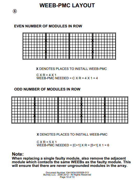
36 Appendix A. Burndy WEEB installation manual - Listed WEEB devices intended for use in bonding BenQ Solar AC Unison modules to mounting structures may be used for grounding as described in the NEC or CEC accordingly. Prior to installation, all bolts that employ bonding and grounding hardware shall have general purpose anti-seize applied onto the bolt threads. Cat. No. WEEB-PMC Racking System Professional Solar RoofTrac, GroundTrac, SolarWedge Torque 15 ft-lbs / 20.5 Nm - Install the WEEB onto the midclamp of racking hardware to bond module frames to mounting rail in accordance with the layout specified in the Burndy installation manual for the pertinent racking system. - Pre-assemble WEEB-PMC onto ProSolar midclamp assembly as shown: - Ensure both sides of the modules are positioned against midclamp and WEEB teeth are underneath module frames. Hand tighten fasteners to keep modules in place since WEEBs are intended for one time use only and cannot be reused. When position is finalized, tighten hardware to specified torque. - Using the approved hardware, install the WEEB Lug at the end of each rail to connect the equipment ground conductor to the system. Each nut/bolt combination that installs a Lug and Bonding Jumper shall be tightened to 10 ft-lbs. / 13.5 Nm of torque as specified in the Burndy manual. - Lug is capable of securing one 6AWG or two 10AWG or two 12 AWG copper conductors. Tighten bolt securing copper conductor to 7 ft-lbs / 10 Nm torque
37
38
39
40
41

42
43
44

45
46

47
Installation Guide Content for P250xV-240 microinverters
 A C M o d u l e Installation Guide Content for P250xV-240 microinverters May 15, 2012 2011-2012 SolarBridge Technologies, Inc. All Rights Reserved. No part of this publication may be reused in any manner
AC Module Installation Guide Content
 AC Module Installation Guide Content for ET-P660250AC May 9, 2012 2011-2012 ET Solar Group All Rights Reserved. No part of this publication may be reused in any manner nor in any form or format without
AC Module Installation Guide Content
 AC Module Installation Guide Content for ET-P660250AC May 9, 2012 2011-2012 ET Solar Group All Rights Reserved. No part of this publication may be reused in any manner nor in any form or format without
Wiser Panel Meter, Model Number WISERCTPM200 Installer s Guide
 Instruction Bulletin EAV85226 08/2014 Wiser Panel Meter, Model Number WISERCTPM200 Installer s Guide Retain for future use. Product Description Kit Contents The Wiser Panel Meter is for use in energy management
GENERAL INSTALLATION MANUAL FOR EGING PV MODULES
 GENERAL INSTALLATION MANUAL FOR EGING PV MODULES PLEASE READ THIS MANUAL CAREFULLY BEFORE INSTALLING OR USING THE MODULES. PLEASE PASS ALONG THE ATTACHED USER MANUAL TO YOUR CUSTOMER. 1. INTRODUCTION This
Model Number Electrical Compatibility Module Connector Type. M250-60-2LL-S22 60 cell PV module MC-4 Type 2 Locking
 TECHNICAL BRIEF M250 Microinverter System Installation Planning The M250 Microinverter The Enphase M250 Microinverter is a powerful and efficient grid-tied microinverter. It is compatible with most 60-cell
Safety and Installation Instructions for AC Modules
 Safety and Installation Instructions for AC Modules United States and Canada Contents of this manual are subject to change without notice. For the latest guide please refer to www.sunpower.com/pvinstallguideacmodule
Energy Communication Unit (ECU)
") Altenergy Power System Energy Communication Unit (ECU) Installation and User Manual (For ECU-3 V3.7) Version:3.0 ALTENERGY POWER SYSTEM INC. All rights reserved TABLE OF CONTENTS 1.0 Introduction... 2
Altenergy Power System Energy Communication Unit (ECU) Installation and User Manual (For ECU-3 V3.7) Version:3.0 ALTENERGY POWER SYSTEM INC. All rights reserved TABLE OF CONTENTS 1.0 Introduction... 2
Application Bulletin 103 - NEC Reference Guide for SolarBridge-Enabled AC Module Installers
 9229 Waterford Centre Dr. Bldg C, Suite 110 Austin, Tx 78758 Application Bulletin 103 - NEC Reference Guide for SolarBridge-Enabled AC Module Installers Current Version: 13 AC Modules are a new product
AMFA-27 AMFA-29. Operator s Manual & Installation Instructions. Rev. 2.5
 AMFA-27 AMFA-29 Operator s Manual & Installation Instructions Rev. 2.5 Date: 17 July, 2010 Permanently-connected, utility Interactive, single-phase, inverters Model AMFA-27 WIND TURBINE INVERTER (240 VAC
RAY-MAX Integrated Solar Power Strip
 RAY-MAX Integrated Solar Power Strip 600008, 600009, 600010, 600208, 600209, 600210 Owner s Manual NEXTRONEX, INC. Revision Date: 10/27/14 Contents 1. Safety Instructions... 3 2. General Equipment Warnings...
Energy Communication Unit (ECU)
") Altenergy Power System Energy Communication Unit (ECU) Installation and User Manual (For ECU-3 V3.8) ALTENERGY POWER SYSTEM INC. All rights reserved TABLE OF CONTENTS 1.0 Introduction... 2 2.0 Installation...
Altenergy Power System Energy Communication Unit (ECU) Installation and User Manual (For ECU-3 V3.8) ALTENERGY POWER SYSTEM INC. All rights reserved TABLE OF CONTENTS 1.0 Introduction... 2 2.0 Installation...
Installation Guide of Sunrise Solartech PV Modules. Term 2013. Contents. Purpose of this guide. General. Safety precaution for installing a solar
 Installation Guide of Sunrise Solartech PV Modules Term 2013 Contents Purpose of this guide General Safety precaution for installing a solar Photovoltaic system Product Identification Mechanical Installation
Disclaimers. Important Notice
 Disclaimers Disclaimers Important Notice Copyright SolarEdge Inc. All rights reserved. No part of this document may be reproduced, stored in a retrieval system, or transmitted, in any form or by any means,
CITY OF LOS ANGELES CALIFORNIA
 BOARD OF BUILDING AND SAFETY COMMISSIONERS VAN AMBATIELOS PRESIDENT E. FELICIA BRANNON VICE-PRESIDENT JOSELYN GEAGA-ROSENTHAL GEORGE HOVAGUIMIAN JAVIER NUNEZ CITY OF LOS ANGELES CALIFORNIA ERIC GARCETTI
What are the basic electrical safety issues and remedies in solar photovoltaic installations?
 What are the basic electrical safety issues and remedies in solar photovoltaic installations? Presented by: Behzad Eghtesady City of Los Angeles Department of Building and Safety Topics Covered Photovoltaic
INSTALLATION GUIDELINES for SOLAR PHOTOVOLTAIC SYSTEMS 1
 City of Cotati Building Division 201 W. Sierra Ave. Cotati, CA 94931 707 665-3637 Fax 792-4604 INSTALLATION GUIDELINES for SOLAR PHOTOVOLTAIC SYSTEMS 1 Any PV system on a new structures should be included
Installation Guide Solar Connect-11
 Installation Guide Solar Connect-11 Version 1.1 Contents Important Product Information 3 System Registration Form 4 Solar Connect-11 Overview 5 Internet & Power Connections 6 Single Phase CT Connections
HP UPS R1500 Generation 3
 HP UPS R1500 Generation 3 Installation Instructions Part Number 650952-001 NOTE: The rating label on the device provides the class (A or B) of the equipment. Class B devices have a Federal Communications
SOLAR ELECTRIC MODULE ES-124 & ES-62T Owners Manual and Installation Guide
 SOLAR ELECTRIC MODULE ES-124 & ES-62T Owners Manual and Installation Guide circuit. Reverse connection will damage the module and may result in fire. CAUTIONS Solar electric modules produce DC electricity
Quick Installation Guide 24-port PoE switch with 2 copper Gigabit ports and 2 Gigabit SFP ports (af Version 15.4W)
") Quick Installation Guide 24-port PoE switch with 2 copper Gigabit ports and 2 Gigabit SFP ports (af Version 15.4W) Table of Contents Introduction.. Power Over Ethernet (PoE) & Features.... Unpacking and
Quick Installation Guide 24-port PoE switch with 2 copper Gigabit ports and 2 Gigabit SFP ports (af Version 15.4W) Table of Contents Introduction.. Power Over Ethernet (PoE) & Features.... Unpacking and
Disclaimers. Important Notice
 Disclaimers Disclaimers Important Notice Copyright SolarEdge Inc. All rights reserved. No part of this document may be reproduced, stored in a retrieval system, or transmitted, in any form or by any means,
Square D Clipsal DIN-Rail Four-Channel Auxiliary Input Unit
 Square D Clipsal DIN-Rail Four-Channel Auxiliary Input Unit SLCLE5504AUX for Use with Wired C-Bus Networks Instruction Bulletin Retain for future use. Square D Clipsal DIN-Rail Four-Channel Auxiliary Input
LIEBERT VNSA Installation Sheet
 LIEBERT VNSA Installation Sheet Description The Liebert vnsa network switch is designed for connecting multiple Ethernet-ready devices and comes in various models. The unit may have: A Liebert icom display
SOLAR PV STANDARD ELECTRICAL PLAN Microinverter Systems for Single Family Dwellings
 *** Provide this document to the inspector along with ALL system installation instructions *** Project Address: Scope: Standard plan for the installation of grounded microinverter solar PV systems, not
2011/2008/2005 NATIONAL ELECTRICAL CODE SOLAR PV CODE COMPLIANCE REFERENCE
 2011/2008/2005 NATIONAL ELECTRICAL CODE SOLAR PV CODE COMPLIANCE REFERENCE PAGE 1 OF 5 This Reference provides a very comprehensive list of aspects of a solar PV installation that could be reviewed, clarifying
YINGLI SOLAR PV MODULES Installation and User Manual
 YINGLI SOLAR PV MODULES Installation and User Manual Revision Date December 24, 2011 Applicable for IEC certified products This manual applies to photovoltaic modules ( PV modules, also commonly known
MCR1900 Media Converter 19-Slot Chassis
 MCR1900 Media Converter 19-Slot Chassis Installation Guide Part #5500304-11 Copyright Statement This document must not be reproduced in any way whatsoever, either printed or electronically, without the
SNQ-60x0-320 Series Data Center Switch. Quick Installation Guide
 Introduction This guide is to assist the reader with the most basic form of installation and connection to switches in this series. As there is more than one switch in this series, the diagrams might slightly
ATS Overhead Table Shelf System INSTRUCTION MANUAL
 ATS Overhead Table Shelf System INSTRUCTION MANUAL ATS Overhead Table Shelf System Instruction Manual Warranty Newport Corporation warrants this product to be free of defects in material and workmanship
How To Plan Out An Array Of Solar Panels
 CITY OF DOWNEY COMMUNITY DEVELOPMENT, BUILDING AND SAFETY 11111 Brookshire Avenue Downey, CA 90241 562.904.7142 (www.downeyca.org) B SECTION 01/01/2011 EFFECTIVE DATE PHOTOVOLTAIC 032 FORM NUMBER 2013
AC Unison Installation Guide PM245PA2
 AC Unison Installation Guide PM245PA2 BenQ Solar AC Unison Solar Power Systems Installation guide Table of Contents 1. AC Unison Solar Power System Overview.2 2. Quick Setup.3 2.1 AC Unison Module... 3
YSmart Technology Co.,Ltd
 YSmart Technology Co.,Ltd GWV Series Grid Tie Microinverter User Manual The copyright of this user manual belong to YSmart TechnologyCompany Limited. Without the written permission of the copyright holder,
This equipment has been tested and found to comply with the limits for a Class B digital device, pursuant to part 15 of the FCC Rules.
 Power Max Level 2 Charging Station en Installation and Operating Instructions This equipment has been tested and found to comply with the limits for a Class B digital device, pursuant to part 15 of the
WARNING: FAILURE TO FOLLOW THESE RULES MAY RESULT IN SERIOUS PERSONAL INJURY CAUTION: INSTALLATION LOCATION:
 Revision Level: 01 Revision Date: 07/07/2011 Please read all instructions carefully to help ensure a correct and SAFE installation of your Second Wind Ultraviolet Germicidal Air Purifier. Failure to do
User Manual. Replus-250 Replus-250A Replus-250B. U.S.A Add: 301 Howard St, Suite 850, San Francisco, CA 94105. T: +1 415 852 7418
 User Manual Replus-250 Replus-250A Replus-250B U.S.A Add: 301 Howard St, Suite 850, San Francisco, CA 94105. T: +1 415 852 7418 Australia Add: 18 Corporate Blvd. Bayswater, VIC 3153, Australia T: +61 481
Solar Panel Installations
 Solar Panel Installations Page 1 of 6 SINGLE-FAMILY RESIDENTIAL CHECKLIST City of Hayward Development Services Department Revised: 7-09-15 PERMIT REQUIREMENTS Permits are required for all solar panel installations.
On/Off Relay Switch and 3-Way Switch Kit
 45637/45638 Wireless Lighting Control On/Off Relay Switch and 3-Way Switch Kit marthome Control the On/Off status of permanently installed lighting, fans and more! www.lowes.com/iris 2012 JASCO Made in
READ THIS MANUAL BEFORE PROCEEDING WITH THE INSTALLATION. FAILURE TO FOLLOW THE INSTALLATION INSTRUCTIONS MAY VOID YOUR WARRANTY!
 READ THIS MANUAL BEFORE PROCEEDING WITH THE INSTALLATION. FAILURE TO FOLLOW THE INSTALLATION INSTRUCTIONS MAY VOID YOUR WARRANTY! The main power to any existing system must be disconnected prior to the
Advantium 2 Plus Alarm
 ADI 9510-B Advantium 2 Plus Alarm INSTALLATION AND OPERATING INSTRUCTIONS Carefully Read These Instructions Before Operating Carefully Read These Controls Corporation of America 1501 Harpers Road Virginia
Ethernet Radio Configuration Guide
 Ethernet Radio Configuration Guide for Gateway, Endpoint, and Repeater Radio Units April 20, 2015 Customer Service 1-866-294-5847 Baseline Inc. www.baselinesystems.com Phone 208-323-1634 FAX 208-323-1834
BroadBand PowerShield. User Manual
 BroadBand PowerShield User Manual 990-0375G 12/2006 Chapter 1 General Information The PowerShield provides a power source for broadband telephony and other DC applications. Safety This Safety Guide contains
Enphase Microinverters and Ungrounded Renewable Energy Systems: Canadian Electrical Code Compliance
 WHITE PAPER Enphase Microinverters and Ungrounded Renewable Energy Systems: Canadian Electrical Code Compliance Overview Enphase has developed a new microinverter family that includes the M250 and new
Mercury Helios 2 ASSEMBLY MANUAL & USER GUIDE
 Mercury Helios 2 ASSEMBLY MANUAL & USER GUIDE TABLE OF CONTENTS INTRODUCTION...1 1.1 MINIMUM SYSTEM REQUIREMENTS 1.1.1 Apple Mac Requirements 1.1.2 PC Requirements 1.1.3 Supported PCIe Cards 1.2 PACKAGE
* DISCLAIMER: Contents. How to Use This Guide: COMMERCIAL INSTALL GUIDE 2
 COMMERCIAL INSTALL GUIDE 2 Contents How to Use This Guide: The first section of this guide is designed to assist you with the installation of your DECK Monitoring hardware. The revenue grade meter and
User Manual. RK-2d / RK-2t. dedicated KVM switch and rackmount screen technology. Designed and manufactured by Austin Hughes
 dedicated KVM switch and rackmount screen technology User Manual RK-2d / RK-2t 1U Short Depth Keyboard Drawer Designed and manufactured by Austin Hughes 751 Legal Information First English printing, October
Daker DK 1, 2, 3 kva. Manuel d installation Installation manual. Part. LE05334AC-07/13-01 GF
 Daker DK 1, 2, 3 kva Manuel d installation Installation manual Part. LE05334AC-07/13-01 GF Daker DK 1, 2, 3 kva Index 1 Introduction 24 2 Conditions of use 24 3 LCD Panel 25 4 Installation 28 5 UPS communicator
7 High-Resolution Digital Photo Frame
 TM 16-1003 User s Guide 7 High-Resolution Digital Photo Frame One demo photo included, as illustrated Please read this user s guide before using your new photo frame. Package contents Photo Frame AC Adapter
Enphase M250 Microinverter
 INSTALLATION AND OPERATION MANUAL Enphase M250 Microinverter with integrated ground no GEC required 141-00022, Rev 01 Contact Information Enphase Energy Inc. 1420 N. McDowell Blvd. Petaluma, CA 94954 http://www.enphase.com
Engage Coupler. Engage Coupler Chase
 TECHNICAL BRIEF Wire Management in an Enphase System The Enphase Microinverter System installs much more quickly than other PV (photovoltaic) system technologies. This is partly due to the plug-and-play
Washer, Electrical Equipment Bond WEEB
 Washer, Electrical Equipment Bond WEEB INSTALLATION INSTRUCTIONS For IronRidge Light & Standard Series Rails Only Please read carefully before installing. Burndy recommends that the sufficient details
PRO 5000 CPE 1D Quick Installation Guide
 PRO 5000 CPE 1D Quick Installation Guide Introduction This Quick Installation Guide covers the basic installation of the PRO 5000 CPE. For more information, refer to the relevant sections in the Product
2013 VTech Printed in China 91-009656-000 US
 Rechargeable Power Pack User s Manual 2013 VTech Printed in China 91-009656-000 US INTRODUCTION The Rechargeable Power Pack makes it easier than ever to keep the InnoTab 3 or InnoTab 3S charged and ready
OASIS-PLUS 120V READ ALL INSTRUCTIONS BEFORE OPERATING READ ALL INSTRUCTIONS BEFORE OPERATING OZONE IS A POWERFUL OXIDIZER AND MUST BE USED WITH CARE
 OASIS-PLUS 120V INFORMATION & OPERATING INSTRUCTIONS READ ALL INSTRUCTIONS BEFORE OPERATING READ ALL INSTRUCTIONS BEFORE OPERATING OZONE IS A POWERFUL OXIDIZER AND MUST BE USED WITH CARE 56041852 WARNING:
Installing the Broadband Global Area Network (BGAN) Fixed Mount Kit
 Fixed Mount Kit") Installing the Broadband Global Area Network (BGAN) Fixed Mount Kit Product description BGAN fixed mount kit Although the BGAN satellite modem terminal is designed for portable use, the BGAN Fixed Mount
Installing the Broadband Global Area Network (BGAN) Fixed Mount Kit Product description BGAN fixed mount kit Although the BGAN satellite modem terminal is designed for portable use, the BGAN Fixed Mount
BPM Series. Metered Rack Mount PDUs. Quick Start Guide. Models Covered:
 WTI Part No.: 13963 Rev.: PM Series Metered Rack Mount PDUs Models Covered: PM-8HS20-1 PM-16VS30-1 PM-24VS30-1 PM-24VS30-D PM-8HS20-2 PM-16VS30-2 PM-24VS30-2 PM-24VS30-Y PM-16VS20-1 PM-24VS20-1 PM-24VS20-D
PERMIT APPLICATION REQUIREMENTS FOR RESIDENTIAL ROOF MOUNTED PHOTOVOLTAIC SYSTEMS
 Butte County Department of Development Services PERMIT CENTER 7 County Center Drive, Oroville, CA 95965 Main Phone (530)538-7601 Permit Center Phone (530)538-6861 Fax (530)538-7785 FORM NO DBP-71 PERMIT
USER GUIDE TURBOCORD TM PORTABLE CHARGER 120V/240V: DUAL VOLTAGE. AeroVironment EV Solutions
 USER GUIDE TURBOCORD TM PORTABLE CHARGER 120V/240V: DUAL VOLTAGE AeroVironment EV Solutions 2013 AeroVironment, Inc. All rights reserved. AeroVironment, EV Solutions, and the AeroVironment logo are trademarks
XC120 XC180. Owner's Guide Conforms to / Conforme à UL std. 458, Toll Free 1 866 295 6775. www.powerbright.com
 WARNING: This Unit employs Components that tend to produce arcs or sparks To prevent fire or explosion, do not install in compartments containing batteries or flammable materials - SHOCK HAZARD. DO NOT
Designing Multi-Tenant and Multi-Home Developments with Enphase Microinverters
 TECHNICAL BRIEF Designing Multi-Tenant and Multi-Home Developments with Enphase Microinverters Overview Enphase Energy s Microinverter system is the ideal solar electric solution for new home developments,
Application Note - Connecting an Electricity Meter to SolarEdge Devices (Europe and APAC)
") February 2015 February 2015 Application Note - Connecting an Electricity Meter to SolarEdge Devices (Europe and APAC) This document describes how to connect an electricity meter to a SolarEdge device (inverters,
February 2015 February 2015 Application Note - Connecting an Electricity Meter to SolarEdge Devices (Europe and APAC) This document describes how to connect an electricity meter to a SolarEdge device (inverters,
Enphase M215 Microinverter
 INSTALLATION AND OPERATION MANUAL Enphase M215 Microinverter 141-00012, Rev 06 Contact Information Enphase Energy Inc. 1420 N. McDowell Blvd. Petaluma, CA 94954 http://www.enphase.com info@enphaseenergy.com
HLWLAN 802.11b/g/n Transceiver Kit
 092524 RevB HLWLAN 802.11b/g/n Transceiver Kit Wireless Communications for OmniLogic Owner s Manual Contents Introduction...1 Installation...2 Configuration...6 Operation...8 Troubleshooting...9 HLWLAN
ES-CAM3A Outdoor IP Camera
 ES-CAM3A Outdoor IP Camera www.etiger.com EN Specifications - Image sensor: 1/3 CMOS, 3.15 MP - Video resolution: 160x90, 320x180, 640x360, 1280x720 (H.264) - Digital zoom: 2x - Focal: 3.6mm, Aperture:
InnoMedia ESBC 9580-4B. Quick Install Guide. www.innomedia.com 1
 InnoMedia ESBC 9580-4B Quick Install Guide www.innomedia.com 1 Table of Contents Introduction 2 Package Contents 2 CAUTION 2 Installation 3 Wall-Mounting Instructions 5 Troubleshooting 6 Appendix A. LED
How To Install And Operate An Ecsecsys Power Supply
 Enecsys Enables OPTIMAL SOLAR SOLUTIONS intelligent reliable power Enecsys Installation and Operation Guide Enecsys Micro inverters Enecsys Gateway Enecsys Repeater Enecsys Double Repeater Document Number:
47611-GB4. Quick-Start Guide 10/100/1000 Mbps 4-Port Gigabit Router IMPORTANT INSTRUCTIONS SAFETY INFORMATION PRE-INSTALLATION CHECKLIST
 IMPORTANT INSTRUCTIONS 1. Read and understand all instructions. Follow all warnings and instructions marked on the product. 2. Do not use this product near water e.g., near a tub, wash basin, kitchen sink
Sense Components. Sense monitor. Antenna assembly. External mounting kit Current sensors. Download the Sense app. Go to sense.com/app.
 Sense Components Sense monitor Antenna assembly External mounting kit Current sensors Download the Sense app. Go to sense.com/app Power cable Technical Specifications Sense is a home energy monitoring
reflecta Super 8 Scanner
 reflecta Super 8 Scanner User Manual 1 FEDERAL COMMUNICATIONS COMMISSION (FCC) STATEMENT This Equipment has been tested and found to comply with the limits for a class B digital device, pursuant to Part
ScreenLogic Wireless Connection Kit. Installation Guide. pool/spa control system
 pool/spa control system ScreenLogic Wireless Connection Kit Installation Guide P/N 520663 - Rev B 8 Technical Support Contact Technical Support at: Sanford, North Carolina (8 A.M. to 5 P.M.) Phone: (800)
Tablet Management Rack 16
 Tablet Management Rack 16 User's Guide Table of Contents Hazard Symbols Review... 2 Components... 2 Charging Set-up... 3-4 LED and Syncing... 4-5 Cleaning and Maintenance... 6 Specifications... 6 Service
User Manual DONGGUAN SHENGYANG INDUSTRIAL CO., LTD. SY WMVC Smart Grid Tie Microinverter. Dongguan Shengyang Industrial Co., Ltd.
 DONGGUAN SHENGYANG INDUSTRIAL CO., LTD SY WMVC Smart Grid Tie Microinverter User Manual Dongguan Shengyang Industrial Co., Ltd. ADD: No. 1 Shangxin Road, New Village, Xin An Community, Chang An Town, Dongguan
GreenWay Solar LED Path and Trail Lighting System. Installation and Owner s Manual
 GreenWay Solar LED Path and Trail Lighting System Installation and Owner s Manual Important Notes and Warnings This installation and instruction manual provides installation, operation, and maintenance
Uninterruptible Power Supply. 500 kva - 750 kva
 9 315 Uninterruptible Power Supply 500 kva - 750 kva T1 and T3 Installation Addendum 164201244-001 Rev. A ------------------------------------------------------------------------ ------------------------------------------------------------------------
PT-6000 Power Tower INSTALLATION MANUAL SPECIFICATIONS
 PT-6000 Power Tower INSTALLATION MANUAL 10.5 9.75 12 22.75 10.75 MAXIMUM SOIL HEIGHT: DO NOT ALLOW FILL TO EXCEED THIS LEVEL! 11.5 4 4 13 Optional PT-BASE for new installations or when previous 2000/6000
About the HotWire 7900 10-Slot Standalone Shelf
 TM HotWire Model 7900 10-Slot Standalone Shelf Installation Instructions Document Number 7900-A2-GN10-10 About the HotWire 7900 10-Slot Standalone Shelf The HotWire 7900 10-Slot Standalone Shelf is designed
Owner s Guide SunPower SPRx Solar Monitor Manual Type
 SunPower-Wired-Remote.book Page i Friday, July 7, 2006 5:09 PM Owner s Guide SunPower SPRx Solar Monitor Manual Type SunPower-Wired-Remote.book Page ii Friday, July 7, 2006 5:09 PM SunPower-Wired-Remote.book
Business Audio System: Music & Messaging MP3 Player. by Grace Digital Audio. User Guide. Model No. GDI-USBM10
 Business Audio System: Music & Messaging MP3 Player by Grace Digital Audio User Guide Model No. GDI-USBM10 User Guide Contents Introduction 2 Safety & General Use Information 2 Features 3 Set Up & Operation
ES-CAM2AU IP Camera. www.etiger.com
 ES-CAM2AU IP Camera www.etiger.com EN Box content Connect your smartphone to the camera - ES-CAM2AU x1 - Mounting bracket x1 - AC Adaptor x1 - User Manual x1 and apps Before using the ES-CAM2AU, download
White Paper SolarEdge Three Phase Inverter System Design and the National Electrical Code. June 2015 Revision 1.5
 White Paper SolarEdge Three Phase Inverter System Design and the National Electrical Code June 2015 Revision 1.5 Shalhevet Bar-Asher; SolarEdge Technologies, Inc. Bill Brooks, PE; Brooks Engineering LLC
INSTALLATION AND USER MANUAL FOR SHARP PHOTOVOLTAIC MODULES A) GENERAL MANUAL
 GENERAL MANUAL") INSTALLATION AND USER MANUAL FOR SHARP PHOTOVOLTAIC MODULES ND-255QCS / ND-250QCS / ND-245QCS ND-250QCJ / ND-245QCJ / ND-240QCJ ND-Q250F7 / ND-Q245F7 IMPORTANT SAFETY INSTRUCTIONS PLEASE READ THIS MANUAL
INSTALLATION AND USER MANUAL FOR SHARP PHOTOVOLTAIC MODULES ND-255QCS / ND-250QCS / ND-245QCS ND-250QCJ / ND-245QCJ / ND-240QCJ ND-Q250F7 / ND-Q245F7 IMPORTANT SAFETY INSTRUCTIONS PLEASE READ THIS MANUAL
Taurus Super-S3 LCM. Dual-Bay RAID Storage Enclosure for two 3.5-inch Serial ATA Hard Drives. User Manual March 31, 2014 v1.2 www.akitio.
 Dual-Bay RAID Storage Enclosure for two 3.5-inch Serial ATA Hard Drives User Manual March 31, 2014 v1.2 www.akitio.com EN Table of Contents Table of Contents 1 Introduction... 1 1.1 Technical Specifications...
dedicated KVM switch and rackmount screen technology User Manual IP-S101 Combo KVM Extender Designed and manufactured by Austin Hughes
 dedicated KVM switch and rackmount screen technology User Manual IP-S101 Combo KVM Extender Designed and manufactured by Austin Hughes 751 Legal Information First English printing, October 2002 Information
VIEW. SLX300 SpeakerLinX IP Zone. Amplifier Installation and Setup Guide. AVoIP
 VIEW SLX300 SpeakerLinX IP Zone Amplifier Installation and Setup Guide TM AVoIP ClearOne 5225 Wiley Post Way Suite 500 Salt Lake City, UT 84116 Telephone 1.800.283.5936 1.801.974.3760 Tech Sales 1.800.705.2103
DRM75A 230V 20/100A DIN rail single phase two wire energy meter
 DRM75A 230V 20/100A DIN rail single phase two wire energy meter 1.1 Safety instruction 1.2 Foreword 1.3 Performance criteria 1.4 Specifications 1.5 Basic errors 1.6 Description 1.7 Dimensions 1.8 Installation
Parallel Redundant Uninterruptible Power Supply
 9 315 Parallel Redundant Uninterruptible Power Supply Installation/Operation Manual 164202013 Rev. D ------------------------------------------------------------------------ ------------------------------------------------------------------------
LevelOne IFE-0500 4-Port PoE + 1-Port TP Industrial Fast Ethernet Switch User Manual
 LevelOne IFE-0500 4-Port PoE + 1-Port TP Industrial Fast Ethernet Switch User Manual Ver. 1.0.0-0711 1 FCC Warning This Equipment has been tested and found to comply with the limits for a Class-A digital
PowerFlex 700S and 700H Frame 12 DC Bus Connector Kit
 PowerFlex 700S and 700H Frame 12 DC Bus Connector Kit Installation Instructions This document provides instructions for the installation of a DC bus connector kit for PowerFlex 700S and 700H frame 12 drives
Aura SSD. for the 2013 Apple Mac Pro INSTALLATION GUIDE
 Aura SSD for the 2013 Apple Mac Pro INSTALLATION GUIDE TABLE OF CONTENTS 1. INTRODUCTION...1 1.1 SYSTEM REQUIREMENTS 1.2 PACKAGE CONTENTS 1.3 ABOUT THIS MANUAL 2. INSTALLATION...2 2.1 PREPARING THE MAC
Enphase Microinverter Model M215
 INSTALLATION AND OPERATION MANUAL Enphase Microinverter Model M215 (M215-60-230) 141-00017, Rev 02c Corporate Headquarters Contact Information Enphase Energy Inc. 1420 N. McDowell Blvd. Petaluma, CA 94954
Getting started with
 PART NO. CMA113 MADE IN CHINA 1. Measuring CAT II 2. Max. voltage 250V ~ 3. Max. current 71 Amp Getting started with Electricity consumption monitoring single phase for homes and some smaller light commercial
Evolution Digital HD Set-Top Box Important Safety Instructions
 Evolution Digital HD Set-Top Box Important Safety Instructions 1. Read these instructions. 2. Keep these instructions. 3. Heed all warnings. 4. Follow all instructions. 5. Do not use this apparatus near
CAUTION RISK OF ELECTRIC SHOCK NO NOT OPEN
 Evolution Digital HD Set-Top Box Important Safety Instructions 1. Read these instructions. 2. Keep these instructions. 3. Heed all warnings. 4. Follow all instructions. 5. Do not use this apparatus near
LED Security Spotlight User Manual
 MOT ION-TR ACKING LED Security Spotlight User Manual www.jascoproducts.com 1-800-654-8483 2 TABLE OF CONTENTS Parts List 3 Questions? Missing Parts? 4 Installation (Wall mount) 6-9 Installation (Eave mount)
All work must conform to the National Electric Code, latest edition, and all other applicable codes and regulations.
 DIVISION 16 ELECTRICAL SECTION 16100 - ELECTRICAL PART 1 - GENERAL SCOPE All electrical work as shown on the drawings and as necessary to provide a complete electrical system. Include primary service,
MTE SERIES RLW. World REACTORS USER MANUAL PART NO. INSTR 030 REL. 090930. 2009 MTE Corporation
 MTE SERIES RLW World REACTORS USER MANUAL PART NO. INSTR 030 REL. 090930 2009 MTE Corporation IMPORTANT USER INFORMATION NOTICE MTE Series RLW reactors are components designed to improve the reliability
RMM2 Heat-Tracing Remote Monitoring Module for the Raychem NGC Control System Installation Instructions
 Heat-Tracing Remote Monitoring Module for the NGC Control System Installation Instructions Tools Required 3 mm slotted screwdriver 3/8 hex key (for -4X only) Approvals Nonhazardous locations Type NM LISTED
CAUTION RISK OF ELECTRIC SHOCK DO NOT OPEN
 BeoLab 7-6 Guide CAUTION RISK OF ELECTRIC SHOCK DO NOT OPEN CAUTION: To reduce the risk of electric shock, do not remove cover (or back). No User-serviceable parts inside. Refer servicing to qualified
Enphase Engage Cable and Accessories
 INSTALLATION MANUAL Enphase Engage Cable and Accessories 141-00016, Rev 03 Corporate Headquarters Contact Information Enphase Energy Inc. 1420 N. McDowell Blvd. Petaluma, CA 94954 USA Phone: +1 707-763-4784
Fronius IG Plus. The next generation grid-connected PV inverter
 Fronius IG Plus The next generation grid-connected PV inverter Maximum energy harvest cloudy or clear The first complete inverter solution. Reliable. Proven. Smart. An outstanding addition to the family: