Instruction Manual. Series 300, 301. For Your Safety AN ODORANT IS ADDED TO THE GAS USED BY THIS WATER HEATER.
|
|
|
- Geoffrey Quinn
- 8 years ago
- Views:
Transcription
1 500 Tennessee Waltz Parkway Ashland City, TN Instruction Manual COMMERCIAL GAS WATER HEATERS MODELS BT-80, BT-100 Series 300, 301 INSTALLATION - OPERATION - SERVICE - MAINTENANCE - LIMITED WARRANTY Low Lead Content WARNING: If the information in these instructions is not followed exactly, a fire or explosion may result causing property damage, personal injury or death. Do not store or use gasoline or other flammable vapors and liquids in the vicinity of this or any other appliance. WHAT TO DO IF YOU SMELL GAS: Do not try to light any appliance. Do not touch any electrical switch; do not use any phone in your building. Immediately call your gas supplier from a neighbor s phone. Follow the gas supplier s instructions. If you cannot reach your gas supplier, call the fire department. Installation and service must be performed by a qualified installer, service agency or the gas supplier. Read and understand this instruction manual and the safety messages herein before installing, operating or servicing this water heater. Failure to follow these instructions and safety messages could result in death or serious injury. This manual must remain with the water heater. For Your Safety AN ODORANT IS ADDED TO THE GAS USED BY THIS WATER HEATER. place these instructions adjacent to heater and notify owner to keep for future reference. Keep this manual in the pocket on heater for future reference whenever maintenance adjustment or service is required. PRINTED

2 Table Of Contents SAFE INSTALLATION, USE AND SERVICE... 3 Approvals...3 GENERAL SAFETY INFORMATION... 4 INTRODUCTION...5 Abbreviations Used...5 Qualified Installer or Service Agency... 5 Preparing for the New Installation... 5 INSTALLATION CONSIDERATIONS Rough In Dimensions...6 Thermometers...7 Facts to Consider About Location... 7 High Altitude...8 Clearances...8 Insulation Blankets...9 Hard Water...9 Circulation Pumps...9 Installation Requirements Gas Supply Systems...10 Gas Pressure Requirements Supply Gas Regulator...10 Mixing Valves...10 Water Piping Closed Water Systems Thermal Expansion Temperature - Pressure Relief Valve Filling the Water Heater Air Requirements...12 Unconfined Space...13 Confined Space...13 Fresh Air Openings for Confined Spaces Outdoor Air Through Two Openings Outdoor Air Through One Opening Outdoor Air Through Two Horizontal Ducts Outdoor Air Through Two Vertical Ducts Air From Other Indoor Spaces Venting...14 Supply Gas Regulator...15 Gas Piping...16 Sediment Traps...17 LIGHTING & OPERATING INSTRUCTIONS... 18,19 TEMPERATURE REGULATION FOR YOUR INFORMATION...20 Start Up Conditions...20 Operational Conditions...21 PERIODIC MAINTENANCE...22 Venting System Inspection Burner Inspection...22 Burner Cleaning...22 Housekeeping...23 Anode Rod Inspection...23 Temperature-Pressure Relief Valve Test Recommended Procedure for Periodic Removal of Lime Deposits from Tank TYPE Commercial Water Heaters Deliming Solvents...24 Tank Cleanout Procedure Deliming Using Flo-Jug Method Draining and Flushing...25 Service...25 LEAKAGE CHECKPOINTS...26 TROUBLESHOOTING GUIDELINES Water Piping Diagrams Notes...34 WARRANTY

3 Safe Installation, Use and Service The proper installation, use and servicing of this water heater is extremely important to your safety and the safety of others. Many safety-related messages and instructions have been provided in this manual and on your own water heater to warn you and others of a potential injury hazard. Read and obey all safety messages and instructions throughout this manual. It is very important that the meaning of each safety message is understood by you and others who install, use, or service this water heater. This is the safety alert symbol. It is used to alert you to potential personal injury hazards. Obey all safety messages that follow this symbol to avoid possible injury or death. DANGER WARNING CAUTION CAUTION DANGER indicates an imminently hazardous situation which, if not avoided, will result in injury or death. WARNING indicates a potentially hazardous situation which, if not avoided, could result in injury or death. CAUTION indicates a potentially hazardous situation which, if not avoided, could result in minor or moderate injury. CAUTION used without the safety alert symbol indicates a potentially hazardous situation which, if not avoided, could result in property damage. All safety messages will generally tell you about the type of hazard, what can happen if you do not follow the safety message, and how to avoid the risk of injury. The California Safe Drinking Water and Toxic Enforcement Act requires the Governor of California to publish a list of substances known to the State of California to cause cancer, birth defects, or other reproductive harm, and requires businesses to warn of potential exposure to such substances. This product contains a chemical known to the State of California to cause cancer, birth defects, or other reproductive harm. This water heater can cause low level exposure to some of the substances listed in the Act. APPROVALS Low Lead Content 3

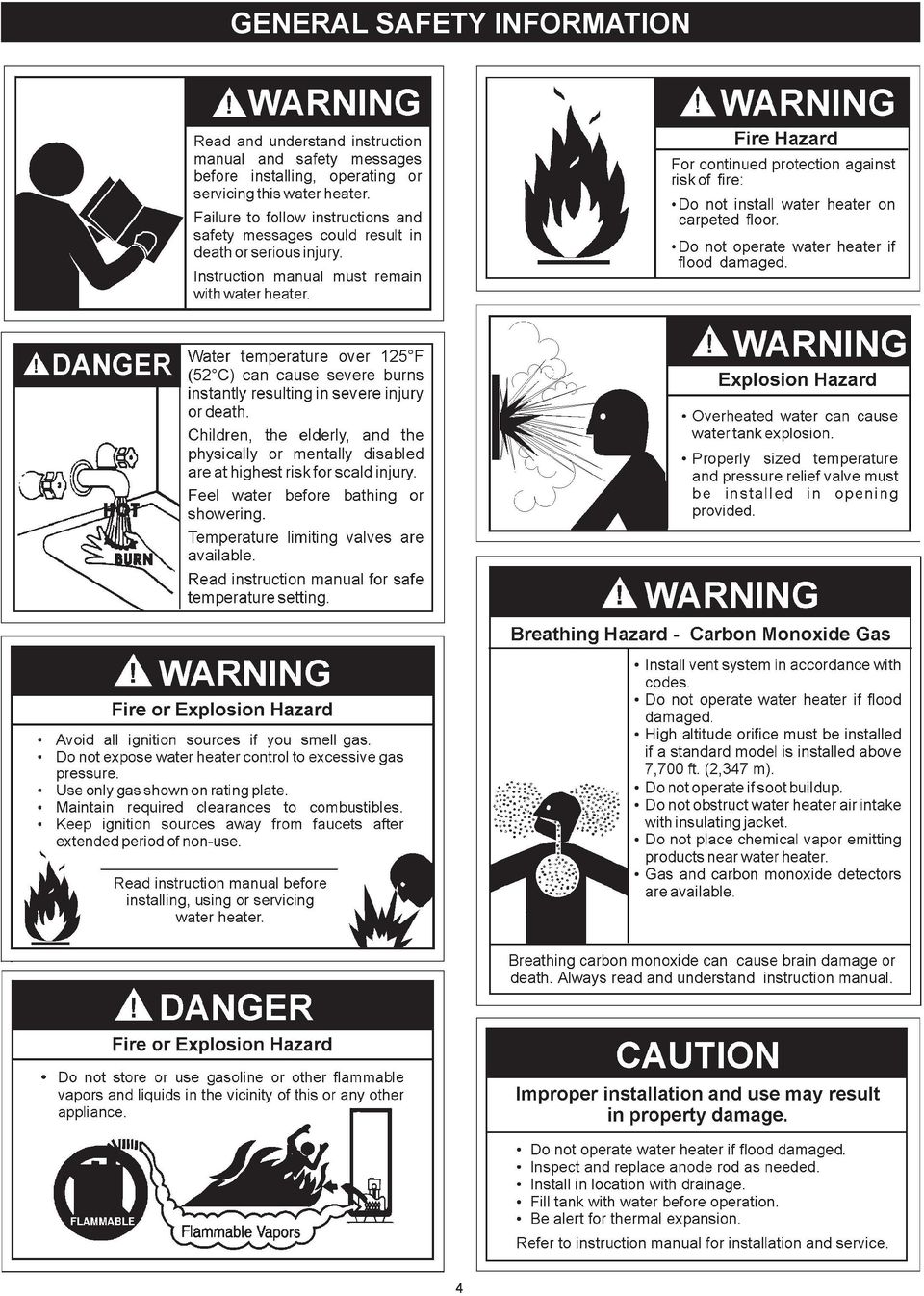
4 general safety INFORMATION 4
5 Introduction Thank You for purchasing this water heater. Properly installed and maintained, it should give you years of trouble free service. Abbreviations Used Abbreviations Found In This Instruction Manual: UL - Underwriters Laboratories Inc. ANSI - American National Standards Institute NFPA - National Fire Protection Association ASME - American Society of Mechanical Engineers AHRI - Air-Conditioning, Heating and Refrigeration Institute CAN - Canada EPACT - Energy Policy Act CSA - Canadian Standards Association This gas-fired water heater is design certified by Underwriters Laboratories Inc. under American National Standard/CSA Standard for Gas Water Heaters ANSI Z CSA 4.3 (current edition). Qualified Installer or Service Agency Installation and service of this water heater requires ability equivalent to that of a Qualified Agency (as defined by ANSI below) in the field involved. Installation skills such as plumbing, air supply, venting, gas supply and electrical supply are required in addition to electrical testing skills when performing service. ANSI Z Sec : Qualified Agency - Any individual, firm, corporation or company that either in person or through a representative is engaged in and is responsible for (a) the installation, testing or replacement of gas piping or (b) the connection, installation, testing, repair or servicing of appliances and equipment; that is experienced in such work; that is familiar with all precautions required; and that has complied with all the requirements of the authority having jurisdiction. If you are not qualified (as defined by ANSI above) and licensed or certified as required by the authority having jurisdiction to perform a given task do not attempt to perform any of the procedures described in this manual. If you do not understand the instructions given in this manual do not attempt to perform any procedures outlined in this manual. Preparing For The Installation 1. Read the General Safety section, page 4 of this manual first and then the entire manual carefully. If you don t follow the safety rules, the water heater will not operate properly. It could cause DEATH, SERIOUS BODILY INJURY AND/OR PROPERTY DAMAGE. This manual contains instructions for the installation, operation, and maintenance of the gas-fired water heater. It also contains warnings throughout the manual that you must read and be aware of. All warnings and all instructions are essential to the proper operation of the water heater and your safety. Since we cannot put everything on the first few pages, READ THE ENTIRE MANUAL BEFORE ATTEMPTING TO INSTALL OR OPERATE THE WATER HEATER. 2. The installation must conform with these instructions and the local code authority having jurisdiction. In the absence of local codes, the installation must comply with the current editions of the National Fuel Gas Code, ANSI Z223.1/ NFPA 54 or CAN/CSA-B149.1 the Natural Gas and Propane Installation Code. All documents are available from the Canadian Standards Association, 8501 East Pleasant Valley Road, Cleveland, OH NFPA documents are also available from the National Fire Protection Association, 1 Batterymarch Park, Quincy, MA If after reading this manual you have any questions or do not understand any portion of the instructions, call the local gas utility or the manufacturer whose name appears on the rating plate. 4. Carefully plan the place where you are going to put the water heater. Correct combustion, vent action, and vent pipe installation are very important in preventing death from possible carbon monoxide poisoning and fires, see Figures 3 and 7. Examine the location to ensure the water heater complies with the Locating the New Water Heater section in this manual. 5. For California installation this water heater must be braced, anchored, or strapped to avoid falling or moving during an earthquake. See instructions for correct installation procedures. Instructions may be obtained from California Office of the State Architect, 400 P Street, Sacramento, CA Massachusetts Code requires this water heater to be installed in accordance with Massachusetts 248-CMR 2.00: State Plumbing Code and 248-CMR

6 Installation considerations ROUGH IN DIMENSIONS FIGURE 1. TABLE 1. Dimensions and Recovery Ratings DIMENSIONS Model Units A B C D E F G H J K L M BT-80 Natural & LP Inches CM 61 1/ / / / / / / NPT 1/2 NPT 11 15/ BT-100 Natural & LP Inches CM 68 5/ / / / / / / /4 NPT 1/2 NPT 11 15/ Model RECOVERY RATINGS Input Approx. Approx. Temp. C Rating Rating Gal. Liter Rise Btu/Hr kw Cap. Cap. F BT-80 75, BT , Recovery ratings based on 80% thermal efficiency. GPH LPH GPH LPH

7 THERMOMETERS (Not Supplied) Thermometers should be obtained and field installed. Thermometers are installed in the system as a means of detecting the temperature of the outlet water supply. This Water Heater has been design certified as complying with ANSI Z CSA 4.3 current edition for water heaters and is considered suitable for: Water (Potable) Heating and Space Heating: All models are considered suitable for water (potable) heating and space heating. HOTTER WATER CAN SCALD: Water heaters are intended to produce hot water. Water heated to a temperature which will satisfy space heating, clothes washing, dish washing, and other sanitizing needs can scald and permanently injure you upon contact. Some people are more likely to be permanently injured by hot water than others. These include the elderly, children, the infirm, or physically/mentally handicapped. If anyone using hot water in your home fits into one of these groups or if there is a local code requiring a certain temperature water at the hot water tap, then you must take special precautions. In addition to using the lowest possible temperature setting that satisfies your hot water needs, a means such as a *Mixing Valve should be used at the hot water taps used by these people or at the water heater. Mixing valves are available at plumbing supply or hardware stores. Consult a qualified installer or service agency. Follow mixing valve manufacturer s instructions for installation of valves. Before changing the factory setting on the thermostat, read the Temperature Regulation section in this manual, see Figures 17 and 18. the structure. For this reason, it is not advisable to install water heater in an attic or upper floor. When such locations cannot be avoided, a suitable metal drain pan should be installed under the water heater. Metal Drain pans are available at your local hardware store. Such a metal drain pan must have a minimum length and width of at least 2 (51 mm) greater than water heater dimensions and must be piped to an adequate drain. The pan must not restrict combustion air flow. Water heater life depends upon water quality, water pressure and the environment in which the water heater is installed. Water heaters are sometimes installed in locations where leakage may result in property damage, even with the use of a drain pan piped to a drain. However, unanticipated damage can be reduced or prevented by a leak detector or water shut-off device used in conjunction with a piped drain pan. These devices are available from some plumbing supply wholesalers and retailers, and detect and react to leakage in various ways: Sensors mounted in the drain pan that trigger an alarm or turn off the incoming water to the water heater when leakage is detected. Sensors mounted in the drain pan that turn off the water supply to the entire home when water is detected in the drain pan. Water supply shut-off devices that activate based on the water pressure differential between the cold water and hot water pipes connected to the water heater. Devices that will turn off the gas supply to a gas water heater while at the same time shutting off its water supply. Facts to Consider About the Location Carefully choose an indoor location for the new water heater, because the placement is a very important consideration for the safety of the occupants in the building and for the most economical use of the water heater. This water heater is not for use in manufactured (mobile) homes or outdoor installation. Whether replacing an old water heater or putting the water heater in a new location, the following critical points must be observed: 1. Select a location indoors as close as practical to the gas vent or chimney to which the water heater vent is going to be connected, and as centralized with the water piping system as possible. 2. Selected location must provide adequate clearances for servicing and proper operation of the water heater. Installation of water heater must be accomplished in such a manner that if the tank or any connections should leak, flow will not cause damage to 7 INSTALLATIONS IN AREAS WHERE FLAMMABLE LIQUIDS (VAPORS) ARE LIKELY TO BE PRESENT OR STORED (GARAGES, STORAGE AND UTILITY AREAS, ETC.): Flammable liquids (such as gasoline, solvents, propane [LP or butane, etc.] and other substances such as adhesives, etc.) emit flammable vapors which can be ignited by a gas water heater s pilot light or main burner. The resulting flashback and fire can cause death or serious burns to anyone in the area, as well as property damage. If installation in such areas is your only option, then installation must be accomplished in a way that the pilot flame and main burner flame are elevated from floor at least 18 inches. While this may reduce chances of flammable vapors, from a floor spill being ignited, gasoline and other flammable substances should never be stored or

8 used in the same room or area containing a gas water heater or other open flame or spark producing appliance. NOTE: Flammable vapors may be drawn by air currents from other areas of the structure to the appliance. Also, the water heater must be located and/or protected so it is not subject to physical damage by a moving vehicle. Clearances Minimum clearances between the water heater and combustible construction are 0 inch at the sides and rear, 4 (102 mm) at the front, and 6 (153 mm) from the vent pipe. Clearance from the top of the jacket is 12 (305 mm) on most models. This water heater must not be installed directly on carpeting. Carpeting must be protected by metal or wood panel beneath the water heater extending beyond the full width and depth of the water heater by at least 3 (76.2 mm) in any direction, or if the water heater is installed in an alcove or closet, the entire floor must be covered by the panel. Failure to heed this warning may result in a fire hazard. FIGURE 2. high altitude Water heaters covered in this manual have been tested and approved for installation at elevations up to 7,700 feet (2,347 m) above sea level. For installation above 7,700 feet (2,347 m), the water heater s Btu input should be reduced at the rate of 4 percent for each 1,000 feet (305 m) above sea level which requires replacement of the burner orifice in accordance with the National Fuel Gas Code ANSI Z223.1/ NFPA 54 or the Natural Gas and Propane Installation Code CAN/ CSA B Contact your local gas supplier for further information. Failure to replace the standard orifice with the proper high altitude orifice when installed at elevations above 7,700 feet (2,347 m) could result in improper and inefficient operation of the water heater, producing carbon monoxide gas in excess of the safe limits. This could result in serious injury or death. Contact your local gas supplier for any specific changes that may be required in your area. A gas water heater cannot operate properly without the correct amount of air for combustion. Do not install in a confined area such as a closet, unless you provide air as shown in the Locating The New Water Heater section. Never obstruct the flow of ventilation air. If you have any doubts or questions at all, call your gas supplier. Failure to provide the proper amount of combustion air can result in a fire or explosion and cause death, serious bodily injury, or property damage. FIGURE 3. If this water heater will be used in beauty shops, barber shops, cleaning establishments, or self-service laundries with dry cleaning equipment, it is imperative that the water heater or water heaters be installed so that combustion and ventilation air be taken from outside these areas. Propellants of aerosol sprays and volatile compounds, (cleaners, chlorine based chemicals, refrigerants, etc.) in addition to being highly flammable in many cases, will also change to corrosive hydrochloric acid when exposed to the combustion products of the water heater. The results can be hazardous, and also cause product failure. 8
 at the front, and 6 (153 mm) from the vent pipe.")
9 INSULATION BLANKETS Breathing Hazard - Carbon Monoxide Gas Do not obstruct water heater air intake with insulating blanket. Gas and carbon monoxide detectors are available. Install water heater in accordance with the instruction manual. Breathing carbon monoxide can cause brain damage or death. Always read and understand instruction manual. Insulation blankets are available to the general public for external use on gas water heaters but are not necessary with these products. The purpose of an insulation blanket is to reduce the standby heat loss encountered with storage tank heaters. The water heaters covered by this manual meet or exceed the Energy Policy Act standards with respect to insulation and standby heat loss requirements, making an insulation blanket unnecessary. Should you choose to apply an insulation blanket to this heater, you should follow these instructions. See the Features and Components section of this manual for identification of components mentioned below. Failure to follow these instructions can restrict the air flow required for proper combustion, potentially resulting in fire, asphyxiation, serious personal injury or death. Do not apply insulation to the top of the water heater, as this will interfere with safe operation of the draft hood. Do not cover the thermostat or the Temperature- Pressure Relief Valve. Do not allow the insulation to come within 2 inches (5 cm) of the floor to prevent blockage of combustion air flow to the burner. Do not cover the instruction manual. Keep it on the side of the water heater or nearby for future reference. Do obtain new warning and instruction labels from the manufacturer for placement on the blanket directly over the existing labels. Do inspect the insulation blanket frequently to make certain it does not sag, thereby obstructing the combustion air flow. Circulation Pumps A circulating pump is used when a system requires a circulating loop or there is a storage tank used in conjunction with the water heater. See Water Piping Diagrams in this manual for installation location of circulating pumps. See the Circulation Pump Wiring Diagrams below for electrical hookup information. Install in accordance with the current edition of the National Electrical Code, NFPA 70 or the Canadian Electrical Code, CSA C22.1. All bronze or stainless steel circulating pumps are recommended for used with commercial water heaters. Some circulating pumps are manufactured with sealed bearings and do not require further lubrication. Some circulating pumps must be periodically oiled. Refer to the pump manufacturer s instructions for lubrication requirements. CIRCULATING PUMP WIRING DIAGRAM STORAGE TANK OR BUILDING RECIRCULATION FIELD SUPPLIED TEMPERATURE CONTROL INSTALLED IN THE STORAGE TANK OR CIRCULATING LOOP RETURN LINE NOTE: USE SEPARATE 120 VAC POWER SUPPLY FOR PUMP CIRCUIT. DO NOT SHARE POWER WITH APPLIANCE AS THIS MAY CAUSE ELECTRICAL LINE NOISE AND LEAD TO ERRATIC CONTROL SYSTEM OPERATION. L1 HOT L2 NEUTRAL 120 VAC POWER FIGURE 4. CIRC PUMP MOTOR CIRCULATING PUMP WIRING DIAGRAM DISHWASHER LOOP WITH TOGGLE SWITCH DISHWASHER TOGGLE SWITCH NOTE: USE SEPARATE 120 VAC POWER SUPPLY FOR PUMP CIRCUIT. DO NOT SHARE POWER WITH APPLIANCE AS THIS MAY CAUSE ELECTRICAL LINE NOISE AND LEAD TO ERRATIC CONTROL SYSTEM OPERATION. L1 HOT FIELD SUPPLIED TEMPERATURE CONTROL INSTALLED IN THE CIRCULATING LOOP RETURN LINE Hard Water Where hard water conditions exist, water softening or the threshold type of water treatment is recommended. This will protect the dishwashers, coffee urns, water heaters, water piping and other equipment. See the Maintenance Section in this manual for sediment and lime scale removal procedures. L2 NEUTRAL 120 VAC POWER figure 5. CIRC PUMP MOTOR 9

10 Installation requirements GAS SUPPLY SYSTEMS Mixing Valves Low pressure building gas supply systems are defined as those systems that cannot under any circumstances exceed 14 W.C. (1/2 PSI Gauge). These systems do not require pressure regulation. Measurements should be taken to insure that gas pressures are stable and fall within the requirements stated on the water heater rating plate. readings should be taken with all gas burning equipment off (static pressure) and with all gas burning equipment running at maximum rate (dynamic pressure). The gas supply pressure must be stable within 1.5 W.C. from static to dynamic pressure to provide good performance. Pressure drops that exceed 1.5 W.C. may cause rough starting, noisy combustion or nuisance outages. Increases or spikes in static pressure during off cycles may cause failure to ignite or in severe cases damage to appliance gas valves. If your low pressure system does not meet these requirements, the installer is responsible for the corrections. High Pressure building supply systems use pressures that exceed 14 W.C. (1/2 PSI Gauge). These systems must use field supplied regulators to lower the gas pressure to less than 14 W.C. (1/2 PSI Gauge). Appliances require gas regulators that are properly sized for the water heater input and deliver the rating plate specified pressures. Gas supply systems where pressure exceeds 5 PSI often require multiple regulators to achieve desired pressures. Systems in excess of 5 PSI building pressure should be designed by gas delivery professionals for best performance. Water heaters connected to gas supply systems that exceed 14 W.C. (1/2 PSI Gauge) at any time must be equipped with a gas supply regulator. GAS PRESSURE REQUIREMENTS Natural gas models require a minimum gas supply pressure of 4.5 W.C. (1.12 kpa). Propane gas models require a minimum gas supply pressure of 11 W.C. (2.74 kpa). The minimum supply pressure is measured while gas is flowing (dynamic pressure). The supply pressure (dynamic) should never fall below the specified minimum supply pressure. The supply pressure should be measured with all gas fired appliances connected to the common main firing at full capacity. If the supply pressure drops more than 1.5 W.C. (0.37 kpa) as gas begins to flow to the water heater then the supply gas system including the gas line and/or the gas regulator may be restricted or undersized. See Supply Gas regulator section and Gas Piping section of this manual. The gas valve on all models has a maximum gas supply pressure limit of 14 W.C. (3.48 kpa) The maximum supply pressure is measured while gas is not flowing (static pressure). SUPPLY GAS REGULATOR The maximum allowable gas supply pressure for this water heater is 14.0 inches W.C. (3.48 kpa). Install a positive lock-up gas pressure regulator in the gas supply line if inlet gas pressure can exceed 14.0 inches W.C. (3.48 kpa) at any time. regulators must be sized/used according to manufacturer s specifications. If a positive lock-up regulator is required follow these instructions: 1. Positive lock-up gas pressure regulators must be rated at or above the input Btu/hr rating of the water heater they supply. 2. Positive lock-up gas pressure regulator(s) should be installed no closer than 3 feet (1 meter) and no farther than 8 feet (2.4 meters) of equivalent length from the water heater s inlet gas connection. 3. After installing the positive lock-up gas pressure regulator(s) an initial nominal supply pressure setting of 7.0 W.C. while the water heater is operating is recommended and will generally provide good water heater operation. Some addition adjustment maybe required later to maintain a steady gas supply pressure. 4. When installing multiple water heaters in the same gas supply system it is recommended that individual positive lock-up gas pressure regulators be installed at each unit. 10 Water temperature over 125 F (52 C) can cause severe burns instantly resulting in severe injury or death. Children, the elderly and the physically or mentally disabled are at highest risk for scald injury. Feel water before bathing or showering. Temperature limiting devices such as mixing valves must be installed when required by codes and to ensure safe temperatures at fixtures. Water heated to a temperature which will satisfy clothes washing, dish washing, and other sanitizing needs can scald and cause permanent injury upon contact. Short repeated heating cycles caused by small hot water uses can cause temperatures at the point of use to exceed the water heater s temperature setting by up to 20 F (11 C). Some people are more likely to be permanently injured by hot water than others. These include the elderly, children, the infirm and the physically/mentally disabled. Table 2 shows the approximate timeto-burn relationship for normal adult skin. If anyone using hot water provided by the water heater being installed fits into one of these groups or if there is a local code or state law requiring a certain water temperature at the point of use, then special precautions must be taken. In addition to using the lowest possible temperature setting that satisfies demand of the application a Mixing Valve should be installed at the water heater or at hot water taps to further reduce system water temperature. See Figure 6. Mixing valves are available at plumbing supply stores. Consult a Qualified Installer or Service Agency. Follow mixing valve manufacturer s instructions for installation of the valves. Table 2. Water Temperature F Time for 1st Degree Burn (Less Severe Burns) Time for Permanent Burns 2nd & 3rd Degree (Most Severe Burns) 110 (normal shower temp.) 116 (pain threshold) minutes 45 minutes minute 5 minutes seconds 25 seconds seconds 5 seconds second 2 seconds 154 instantaneous 1 second (U.S. Government Memorandum, C.P.S.C., Peter L. Armstrong, Sept. 15,1978) COLD WATER INLET TEMPERED WATER OUTLET HOT WATER OUTLET CHECK VALVE TO TANK INLET Figure TO 15 (30-38 cm) MIXING VALVE CHECK VALVE

11 Water Piping WATER (POTABLE) HEATING AND SPACE HEATING This water heater shall not be connected to any heating systems or component(s) used with a non-potable water heating appliance. All piping components connected to this unit for space heating applications shall be suitable for use with potable water. Toxic chemicals, such as those used for boiler treatment shall not be introduced into this system. When the system requires water for space heating at temperatures higher than required for domestic water purposes, a mixing valve must be installed. Please refer to Figure 2 for suggested piping arrangement. These water heaters cannot be used in space heating applications only. Closed Water Systems Water supply systems may, because of code requirements or such conditions as high line pressure, among others, have installed devices such as pressure reducing valves, check valves, and back flow preventers. Devices such as these cause the water system to be a closed system. Thermal Expansion As water is heated, it expands (thermal expansion). In a closed system the volume of water will grow when it is heated. As the volume of water grows there will be a corresponding increase in water pressure due to thermal expansion. Thermal expansion can cause premature tank failure (leakage). This type of failure is not covered under the limited warranty. Thermal expansion can also cause intermittent Temperature-Pressure Relief Valve operation: water discharged from the valve due to excessive pressure build up. This condition is not covered under the limited warranty. The Temperature-Pressure Relief Valve is not intended for the constant relief of thermal expansion. A properly sized thermal expansion tank must be installed on all closed systems to control the harmful effects of thermal expansion. Contact a local plumbing service agency to have a thermal expansion tank installed. FIGURE 7. NOTE: To protect against untimely corrosion of hot and cold water fittings, it is strongly recommended that di-electric unions or couplings be installed on this water heater when connected to copper pipe. Figure 7 shows the typical attachment of the water piping to the water heater. The water heater is equipped with 1 NPT threaded nipple (75 gallon models) or 1.25 NPT threaded nipple (100 gallon models) water connections. Temperature-Pressure Relief Valve Explosion Hazard Temperature-Pressure Relief Valve must comply with ANSI Z CSA 4.4 and ASME code. Properly sized temperaturepressure relief valve must be installed in opening provided. Can result in overheating and excessive tank pressure. Can cause serious injury or death. This water heater is provided with a properly rated/sized and certified combination Temperature-Pressure Relief Valve (T&P valve) by the manufacturer. The valve is certified by a nationally recognized testing laboratory that maintains periodic inspection of production of listed equipment of materials as meeting the requirements for Relief Valves for Hot Water Supply Systems, ANSI Z21.22 CSA 4.4, and the code requirements of ASME. If replaced, the new T&P valve must meet the requirements of local codes, but not less than a combination Temperature-Pressure Relief Valve rated/sized and certified as indicated in the above paragraph. The new valve must be marked with a maximum set pressure not to exceed the marked hydrostatic working pressure of the water heater (150 psi = 1,035 kpa) and a discharge capacity not less than the water heater Btu/hr or kw input rate as shown on the water heater s model rating label. 11

12 Note: In addition to the factory installed Temperature-Pressure Relief Valve on the water heater, each remote storage tank that may be installed and piped to a water heating appliance must also have its own properly sized, rated and approved Temperature- Pressure Relief Valve installed. Call the toll free technical support phone number listed on the back cover of this manual for technical assistance in sizing a Temperature-Pressure Relief Valve for remote storage tanks. For safe operation of the water heater, the Temperature-Pressure Relief Valve must not be removed from its designated opening nor plugged. The Temperature-Pressure Relief Valve must be installed directly into the fitting of the water heater designed for the relief valve. Install discharge piping so that any discharge will exit the pipe within 6 inches (15.2 cm) above an adequate floor drain, or external to the building. In cold climates it is recommended that it be terminated at an adequate drain inside the building. Be certain that no contact is made with any live electrical part. The discharge opening must not be blocked or reduced in size under any circumstances. Excessive length, over 30 feet (9.14 m), or use of more than four elbows can cause restriction and reduce the discharge capacity of the valve. No valve or other obstruction is to be placed between the Temperature-Pressure Relief Valve and the tank. Do not connect discharge piping directly to the drain unless a 6 (15.2 cm) air gap is provided. To prevent bodily injury, hazard to life, or property damage, the relief valve must be allowed to discharge water in adequate quantities should circumstances demand. If the discharge pipe is not connected to a drain or other suitable means, the water flow may cause property damage. CAUTION Water Damage Hazard Temperature-Pressure Relief Valve discharge pipe must terminate at adequate drain. T&P Valve Discharge Pipe Requirements: Shall not be smaller in size than the outlet pipe size of the valve, or have any reducing couplings or other restrictions. Shall not be plugged or blocked. Shall not be exposed to freezing temperatures. Shall be of material listed for hot water distribution. Shall be installed so as to allow complete drainage of both the Temperature-Pressure Relief Valve and the discharge pipe. Must terminate a maximum of six inches above a floor drain or external to building. In cold climates, it is recommended that discharge pipe be terminated at an adequate drain inside building. Shall not have any valve or other obstruction between the relief valve and the drain. Burn hazard. Hot water discharge. Keep clear of Temperature- Pressure Relief Valve discharge outlet. The Temperature-Pressure Relief Valve must be manually operated at least twice a year. Caution should be taken to ensure that (1) no one is in front of or around the outlet of the Temperature-Pressure Relief Valve discharge line, and (2) the water manually discharged will not cause any bodily injury or property damage because the water may be extremely hot. If after manually operating the valve, it fails to completely reset and continues to release water, immediately close the cold water inlet to the water heater, follow the draining instructions in this manual, and replace the Temperature- Pressure Relief Valve with a properly rated/sized new one. Note: The purpose of a Temperature-Pressure Relief Valve is to prevent excessive temperatures and pressures in the storage tank. The T&P valve is not intended for the constant relief of thermal expansion. A properly sized thermal expansion tank must be installed on all closed systems to control thermal expansion, see Closed Water Systems and Thermal Expansion on page 11. If you do not understand these instructions or have any questions regarding the Temperature-Pressure Relief Valve call the toll free number listed on the back cover of this manual for technical assistance. 12 Filling the Water Heater Never use this water heater unless it is completely full of water. To prevent damage to the tank, the tank must be filled with water. Water must flow from the hot water faucet before turning ON gas to the water heater. To fill the water heater with water: 1. Close the water heater drain valve by turning the handle to the right (clockwise). The drain valve is on the lower front of the water heater. 2. Open the cold water supply valve to the water heater. NOTE: The cold water supply valve must be left open when the water heater is in use. 3. To insure complete filling of the tank, allow air to exit by opening the nearest hot water faucet. Allow water to run until a constant flow is obtained. This will let air out of the water heater and the piping. 4. Check all water piping and connections for leaks. Repair as needed. Air Requirements Breathing Hazard - Carbon Monoxide Gas Install water heater in accordance with the Instruction Manual and NFPA 54 or CAN/CSA-B To avoid injury, combustion and ventilation air must be taken from outdoors. Do not place chemical vapor emitting products near water heater. Breathing carbon monoxide can cause brain damage or death. Always read and understand instruction manual. For safe operation an adequate supply of fresh uncontaminated air for combustion and ventilation must be provided. An insufficient supply of air can cause recirculation of combustion products resulting in contamination that may be hazardous to life. Such a condition often will result in a yellow, luminous burner flame, causing sooting of the combustion chamber, burners and flue tubes and creates a risk of asphyxiation. Do not install the water heater in a confined space unless an adequate supply of air for combustion and ventilation is brought in to that space using the methods described in the Confined Space section that follows. Never obstruct the flow of ventilation air. If you have any doubts or questions at all, call your gas supplier. Failure to provide the proper

13 amount of combustion air can result in a fire or explosion and cause property damage, serious bodily injury or death. Outdoor Air Through Two Openings Unconfined Space An Unconfined Space is one whose volume is not less than 50 cubic feet per 1,000 Btu/hr (4.8 cubic meters per kw) of the total input rating of all appliances installed in the space. Rooms communicating directly with the space, in which the appliances are installed, through openings not furnished with doors, are considered a part of the unconfined space. Makeup air requirements for the operation of exhaust fans, kitchen ventilation systems, clothes dryers and fireplaces shall also be considered in determining the adequacy of a space to provide combustion, ventilation and dilution air. Unusually Tight Construction In unconfined spaces in buildings, infiltration may be adequate to provide air for combustion, ventilation and dilution of flue gases. However, in buildings of unusually tight construction (for example, weather stripping, heavily insulated, caulked, vapor barrier, etc.) additional air must be provided using the methods described in the Confined Space section that follows. Confined Space A Confined Space is one whose volume is less than 50 cubic feet per 1,000 Btu/hr (4.8 cubic meters per kw) of the total input rating of all appliances installed in the space. Openings must be installed to provide fresh air for combustion, ventilation and dilution in confined spaces. The required size for the openings is dependent on the method used to provide fresh air to the confined space and the total Btu/hr input rating of all appliances installed in the space. Direct Vent Appliances Appliances installed in a Direct Vent configuration that derive all air for combustion from the outdoor atmosphere through sealed intake air piping are not factored in the total appliance input Btu/hr calculations used to determine the size of openings providing fresh air into confined spaces. Figure 8. The confined space shall be provided with two permanent openings, one commencing within 12 inches (300 mm) of the top and one commencing within 12 inches (300 mm) of the bottom of the enclosure. The openings shall communicate directly with the outdoors. See Figure 8. Each opening shall have a minimum free area of 1 square inch per 4,000 Btu/hr (550 mm2 per kw) of the aggregate input rating of all appliances installed in the enclosure. Each opening shall not be less than 100 square inches (645 cm2). Outdoor Air Through One Opening Exhaust Fans Where exhaust fans are installed, additional air shall be provided to replace the exhausted air. When an exhaust fan is installed in the same space with a water heater, sufficient openings to provide fresh air must be provided that accommodate the requirements for all appliances in the room and the exhaust fan. Undersized openings will cause air to be drawn into the room through the water heater s vent system causing poor combustion. Sooting, serious damage to the water heater and the risk of fire or explosion may result. It can also create a risk of asphyxiation. Louvers and Grilles The free areas of the fresh air openings in the instructions that follow do not take in to account the presence of louvers, grilles or screens in the openings. The required size of openings for combustion, ventilation and dilution air shall be based on the net free area of each opening. Where the free area through a design of louver or grille or screen is known, it shall be used in calculating the size of opening required to provide the free area specified. Where the louver and grille design and free area are not known, it shall be assumed that wood louvers will have 25% free area and metal louvers and grilles will have 75% free area. Non motorized louvers and grilles shall be fixed in the open position. Fresh Air Openings For Confined Spaces The following instructions shall be used to calculate the size, number and placement of openings providing fresh air for combustion, ventilation and dilution in confined spaces. The illustrations shown in this section of the manual are a reference for the openings that provide fresh air into confined spaces only. Do not refer to these illustrations for the purpose of vent installation. See Venting Installation on page 18 for complete venting installation instructions. 13 Figure 9. Alternatively a single permanent opening, commencing within 12 inches (300 mm) of the top of the enclosure, shall be provided. See Figure 9. The water heater shall have clearances of at least 1 inch (25 mm) from the sides and back and 6 inches (150 mm) from the front of the appliance. The opening shall directly communicate with the outdoors or shall communicate through a vertical or horizontal duct to the outdoors or spaces that freely communicate with the outdoors and shall have a minimum free area of the following: 1. 1 square inch per 3000 Btu/hr (733 mm 2 per kw) of the total input rating of all appliances located in the enclosure, and 2. Not less than the sum of the areas of all vent connectors in the space.

14 Outdoor Air Through Two Horizontal Ducts enclosure. The vertical ducts shall communicate directly with the outdoors. See Figure 11. Each duct opening shall have a minimum free area of 1 square inch per 4,000 Btu/hr (550 mm2 per kw) of the aggregate input rating of all appliances installed in the enclosure. When ducts are used, they shall be of the same cross sectional area as the free area of the openings to which they connect. The minimum dimension of rectangular air ducts shall be not less than 3 inches. Air From Other Indoor Spaces Figure 10. The confined space shall be provided with two permanent horizontal ducts, one commencing within 12 inches (300 mm) of the top and one commencing within 12 inches (300 mm) of the bottom of the enclosure. The horizontal ducts shall communicate directly with the outdoors. See Figure 10. Each duct opening shall have a minimum free area of 1 square inch per 2,000 Btu/hr (1100 mm2 per kw) of the aggregate input rating of all appliances installed in the enclosure. When ducts are used, they shall be of the same cross sectional area as the free area of the openings to which they connect. The minimum dimension of rectangular air ducts shall be not less than 3 inches. Outdoor Air Through Two Vertical Ducts The illustrations shown in this section of the manual are a reference for the openings that provide fresh air into confined spaces only. Do not refer to these illustrations for the purpose of vent installation. See Venting Installation on page 18 for complete venting installation instructions. Figure 12. The confined space shall be provided with two permanent openings, one commencing within 12 inches (300 mm) of the top and one commencing within 12 inches (300 mm) of the bottom of the enclosure. See Figure 12. Each opening shall communicate directly with an additional room(s) of sufficient volume so that the combined volume of all spaces meets the criteria for an Unconfined Space. Each opening shall have a minimum free area of 1 square inch per 1,000 Btu/hr (2200 mm2 per kw) of the aggregate input rating of all appliances installed in the enclosure. Each opening shall not be less than 100 square inches (645 cm2). Venting Figure 11. The confined space shall be provided with two permanent vertical ducts, one commencing within 12 inches (300 mm) of the top and one commencing within 12 inches (300 mm) of the bottom of the 14

15 If the water heater is being installed as a replacement for an existing heater in pre-existing venting, a thorough inspection of existing venting system must be performed prior to any installation work. VENT DAMPERS - Any vent damper, whether it is operated thermally or otherwise must be removed if its use inhibits proper drafting of the water heater. Thermally Operated Vent Dampers: this gas-fired water heater has a thermal efficiency at or above 80% which may produce a relatively low flue gas temperature. Such temperatures may not be high enough to properly open thermally operated vent dampers. This would cause spillage of the flue gases and may cause carbon monoxide poisoning. Vent dampers must bear evidence of certification as complying with the current edition of the American National Standard ANSI Z21.66 CGA 6.14 (covering electrically and mechanically actuated vent dampers). Before installation of any vent damper, consult the local gas utility for further information. To insure proper venting of this gas-fired water heater, the correct vent pipe diameter must be utilized. Any additions or deletions of other gas appliances on a common vent with this water heater may adversely affect the operation of the water heater. Consult your gas supplier if any such changes are planned. For proper venting in certain installations, a larger diameter vent pipe may be necessary. Consult your gas supplier to aid you in determining the proper venting for your water heater from the vent tables in the current edition of the National Fuel Gas Code ANSI Z223.1/NFPA 54 or the Natural Gas and Propane Installation Code CAN\CSA B Periodically check the venting system for signs of obstruction or deterioration and replace if needed. The combustion and ventilation air flow must not be obstructed. The water heater with draft hood installed must be connected to a chimney or listed vent pipe system, which terminates to the outdoors. Never operate the water heater unless it is vented to the outdoors and has adequate air supply to avoid risks of improper operation, explosion or asphyxiation. For proper draft hood attachment, the draft hood legs may be angled slightly inward. Place the draft hood legs in the receiving holes on the top of the water heater. The legs will snap in the holes to give a tight fit. Secure draft hood with the supplied brackets. Place the vent pipe over the draft hood. With the vent pipe in position, drill a small hole through both the vent pipe and draft hood. Secure them together with a sheet metal screw. See Figure 13. Obstructed or deteriorated vent systems may present serious health risk or asphyxiation. The vent pipe from the water heater must be no less than the diameter of the draft hood outlet on the water heater and must slope upward at least 1/4 inch per linear foot (21 mm per meter). See Figure 14. All vent gases must be completely vented to the outdoors of the structure (dwelling). Install only the draft hood provided with the new water heater and no other draft hood. Vent pipes must be secured at each joint with sheet metal screws. FIGURE 14. There must be a minimum of 6 (153 mm) clearance between single wall vent pipe and any combustible material. Fill and seal any clearance between single wall vent pipe and combustible material with mortar mix, cement, or other noncombustible substance. For other than single wall, follow vent pipe manufacturer s clearance specifications. To insure a tight fit of the vent pipe in a brick chimney, seal around the vent pipe with mortar mix cement. Failure to have required clearances between vent piping and combustible material will result in a fire hazard. Be sure vent pipe is properly connected to prevent escape of dangerous flue gases which could cause deadly asphyxiation. FIGURE 13. Chemical vapor corrosion of the flue and vent system may occur if air for combustion contains certain chemical vapors. Spray can propellants, cleaning solvents, refrigerator and air conditioner refrigerants, swimming pool chemicals, calcium and sodium chloride, waxes, bleach and process chemicals are typical compounds which are potentially corrosive. 15

16 Gas Piping TABLE 4. Contact your local gas service company to ensure that adequate gas service is available and to review applicable installation codes for your area. Size the main gas line in accordance with Table 3. The figures shown are for straight lengths of pipe at 0.5 in. W.C. pressure drop, which is considered normal for low pressure systems. Note: Fittings such as elbows, tees and line regulators will add to the pipe pressure drop. Also refer to the current editions of the National Fuel Gas Code (NFPA 54) or Natural Gas and Propane Installation Code (CAN/CSA B149.1). Make sure gas supplied is same type listed on model rating plate. The inlet gas pressure must not exceed 14 inch water column (2.6 kpa) for natural and propane (L.P.) gas. The minimum inlet gas pressure shown on rating plate is that which will permit firing at rated input. If the gas control valve is subjected to pressures exceeding 1/2 pound per square inch (3.5 kpa), the damage to the gas control valve could result in a fire or explosion from leaking gas. If the main gas line shut-off serving all gas appliances is used, also turn off the gas at each appliance. Leave all gas appliances shut off until the water heater installation is complete. A gas line of sufficient size must be run to the water heater. Consult the current edition of National Fuel Gas Code ANSI Z223.1/NFPA 54 or the Natural Gas and Propane Installation Code CAN/CSA B149.1 and your gas supplier concerning pipe size. There must be: A readily accessible manual shut off valve in the gas supply line serving the water heater, and A sediment trap ahead of the gas control valve to help prevent dirt and foreign materials from entering the gas control valve. A flexible gas connector or a ground joint union between the shut off valve and control valve to permit servicing of the unit. Be sure to check all the gas piping for leaks before lighting the water heater. Use a soapy water solution, not a match or open flame. Rinse off soapy solution and wipe dry. The minimum inlet gas pressure shown on the rating plate is that which will permit firing at the rated input. TABLE 3. GAS SUPPLY LINE SIZES (IN INCHES)* MAXIMUM CAPACITY OF PIPE IN CUBIC FEET PER HOUR LENGTH IN FEET NOMINAL IRON PIPE SIZES (INCHES) INPUT IN THOUSANDS (BTU/HR) 1/2" 3/4" 1" 1 1/4" 1 1/2" 2" 2 1/2" 3" 4" LENGTH IN METERS NOMINAL IRON PIPE SIZES (INCHES) INPUT IN KW 1/2" 3/4" 1" 1 1/4" 1 1/2" 2" 2 1/2" 3" 4" Use pipe joint compound or teflon tape marked as being resistant to the action of petroleum [Propane (L.P.)] gases. The water heater and its gas connection must be leak tested before placing the water heater in operation. The water heater and its individual shut-off valve shall be disconnected from the gas supply piping system during any pressure testing of that system at test pressures in excess of 1/2 pound per square inch (3.5 kpa). It shall be isolated from the gas supply piping system by closing its individual manual shut-off valve during any pressure testing of the gas supply piping system at test pressures equal to or less than 1/2 pound per square inch (3.5 kpa). Connecting the gas piping to the gas control valve of the water heater can be accomplished by either of the two methods shown in Figures 15 and 16. FIGURE 15. GAS PIPING WITH FLEXIBLE CONNECTOR. FIGURE 16. GAS PIPING WITH ALL BLACK IRON PIPE TO GAS CONTROL.
 or Natural Gas and Propane Installation Code (CAN/CSA B149.1).")
17 SEDIMENT TRAPS A sediment trap shall be installed as close to the inlet of the water heater as practical at the time of water heater installation. The sediment trap shall be either a tee fitting with a capped nipple in the bottom outlet or other device recognized as an effective sediment trap. If a tee fitting is used, it shall be installed in conformance with one of the methods of installation shown in the Figures 15 and 16. Contaminants in the gas lines may cause improper operation of the gas control valve that may result in fire or explosion. Before attaching the gas line be sure that all gas pipe is clean on the inside. To trap any dirt or foreign material in the gas supply line, a sediment trap must be incorporated in the piping. The sediment trap must be readily accessible. Install in accordance with the Gas Piping section. Refer to the current edition of the National Fuel Gas Code, ANSI Z223.1/NFPA 54 or the Natural Gas and Propane Installation Code CAN/CSA B

18 18

19 FOR YOUR SAFETY READ BEFORE LIGHTING WARNING: If you do not follow these instructions exactly, a fire or explosion may result causing property damage, personal injury or loss of life. BEFORE LIGHTING: ENTIRE SYSTEM MUST BE FILLED WITH WATER AND AIR PURGED AT FAUCETS. A. This appliance has a pilot which must be lighted by hand. When lighting the pilot, follow these instructions exactly. B. BEFORE LIGHTING: smell all around the appliance area for gas. Be sure to smell next to the floor because some gas is heavier than air and will settle on the floor. WHAT TO DO IF YOU SMELL GAS Do not try to light any appliance. Do not touch any electric switch; do not use any phone in your building. Immediately call your gas supplier from a neighbor s phone. Follow the gas supplier s instructions. If you cannot reach your gas supplier, call the fire department. C. Use only your hand to push down or turn the gas control knob. Never use tools. If the knob will not push down or turn by hand, don t try to repair it, call a qualified service technician. Force or attempted repair may result in a fire or explosion. D. Do not use this appliance if any part has been under water. Immediately contact a qualified installer or service agency to replace a flooded water heater. Do not attempt to repair the unit! It must be replaced! LIGHTING INSTRUCTIONS GAS CONTROL TOP VIEW FIGURE D 1. STOP! Read the safety information above on this label. 2. Set the thermostat to the lowest setting by turning thermostat dial fully clockwise until it stops. 3. Push the gas control knob down slightly and turn clockwise to OFF (Figure A). NOTE: Gas control knob CANNOT be turned from PILOT to OFF unless it is pushed down slightly. Do not force. 4. Remove the inner and outer doors located below and behind the gas control unit. 5. Wait five (5) minutes to clear out any gas. If you then smell gas STOP! Follow B in the safety information above on this label. If you do not smell gas, go to the next step. 6. Find Pilot. Follow metal tube from the bottom, right of the gas control to the pilot burner. (Figure D). 7. Turn gas control knob counterclockwise to PILOT (Figure B). 8. Push gas control knob down all the way and hold it down. Immediately light the pilot with a match. Continue to hold the gas control knob down for about one (1) minute after the pilot is lit. Release the gas control knob and it will pop back up. Pilot should remain lit. If it goes out, repeat Steps 3 through 8. It may take several minutes for air to clear the lines, before the pilot will light. If knob does not pop up when released, stop and immediately call your service technician or gas supplier. If the pilot will not stay lit after several tries, turn the gas control knob to OFF (Figure A) and call your service technician or gas supplier. 9. Replace inner and outer burner doors. 10. At arm s length away, turn the gas control knob counterclockwise to ON (Figure C). 11. Set thermostat to desired setting (See Figure). CAUTION: Hotter water increases the risk of scald injury. Consult the instruction manual before changing temperature. TO TURN OFF GAS TO APPLIANCE 1. Set the thermostat to lowest setting. 2. Push gas control knob down slightly and turn clockwise to OFF. Do not force, see Figure A. 19

20 TEMPERATURE REGULATION Short repeated heating cycles caused by small hot water uses can cause temperatures at the point of use to exceed the thermostat setting by up to 30 F (16.7 C). If you experience this type of use you should consider using lower temperature settings to reduce scald hazards. Any water heater s intended purpose is to heat water. Hot water is needed for cleansing, cleaning, and sanitizing (bodies, dishes, clothing). Untempered hot water can present a scald hazard. Depending on the time element, and the people involved (adults, children, elderly, infirm, etc.) scalding may occur at different temperatures. Never allow small children to use a hot water tap, or to draw their own bath water. Never leave a child or handicapped person unattended in a bathtub or shower. NOTE: A water temperature range of 120 F-140 F (49 C-60 C) is recommended by most dishwasher manufacturers. The thermostat of this water heater has been factory set at its lowest position (pilot lighting). It is adjustable and must be reset to the desired temperature setting to reduce the risk of scald injury. The mark ( ) indicative of approximately 120 F (49 C) is preferred starting point. Some States have a requirement for a lower setting. Turn the water temperature dial clockwise ( ) to decrease the temperature, or counterclockwise ( ) to increase the temperature. Should overheating occur or the gas supply fail to shut off, turn off the manual gas control valve to the water heater. HOTTER WATER CAN SCALD: Water heaters are intended to produce hot water. Water heated to a temperature which will satisfy space heating, clothes washing, dish washing, and other sanitizing needs can scald and permanently injure you upon contact. Some people are more likely to be permanently injured by hot water than others. These include the elderly, children, the infirm, or physically/mentally handicapped. If anyone using hot water in your home fits into one of these groups or if there is a local code or state law requiring a certain temperature water at the hot water tap, then you must take special precautions. In addition to using the lowest possible temperature setting that satisfies your hot water needs, a means such as a mixing valve should be used at the hot water taps used by these people or at the water heater. Mixing valves are available at plumbing supply or hardware stores, see Figure 2. Follow manufacturer s instructions for installation of the valves. Before changing the factory setting on the thermostat, read the Temperature Regulation section in this manual, see Figures 17 and 18. Water Temperature F FIGURE 17. Time for 1st Degree Burn (Less Severe Burns) Time for Permanent Burns 2nd & 3rd Degree (Most Severe Burns) 110 (normal shower temp.) 116 (pain threshold) minutes 45 minutes minute 5 minutes seconds 25 seconds seconds 5 seconds second 2 seconds 154 instantaneous 1 second (U.S. Government Memorandum, C.P.S.C., Peter L. Armstrong, Sept. 15,1978) FIGURE 18. START UP CONDITIONS DRAFT HOOD OPERATION Check draft hood operation by performing a worst case depressurization of the building. With all doors and windows closed, and with all air handling equipment and exhaust fans operating such as furnaces, clothes dryers, range hoods and bathroom fans, a match flame should still be drawn into the draft hood of the water heater with its burner firing. If the flame is not drawn toward the draft hood, shut off water heater and make necessary air supply changes to correct. CONDENSATION Whenever the water heater is filled with cold water, some condensate will form while the burner is on. A water heater may FOR YOUR INFORMATION 20 appear to be leaking when in fact the water is condensation. This usually happens when: a. A new water heater is filled with cold water for the first time. b. Burning gas produces water vapor in water heaters, particularly high efficiency models where flue temperatures are lower. c. Large amounts of hot water are used in a short time and the refill water in the tank is very cold. Moisture from the products of combustion condense on the cooler tank surfaces and form drops of water which may fall onto the burner or other hot surfaces to produce a sizzling or frying noise. Excessive condensation can cause pilot outage due to water running down the flue tube onto the main burner and putting out the pilot.
 scalding may occur at different temperatures.")
Instruction Manual for Residential Gas Water Heaters
 Instruction Manual for Residential Gas Water Heaters NOT FOR USE IN MANUFACTURED (MOBILE) HOMES GAMA certification applies to all residential gas water heaters with capacities of 20 to 100 gallons with
PURCHASED. IF YOU ARE UNSUCCESSFUL, PLEASE WRITE TO THE COMPANY LISTED ON THE RATING PLATE ON THE WATER HEATER.
 Instruction Manual COMMERCIAL GAS WATER HEATERS MODELS CG(N,L)075075, CG(N,L)075100 Series 300, 301 300 Maddox Simpson Parkway Lebanon, TN 37090 Phone: 615-889-8900 Fax: 615-547-1000 Technical Service
COMMERCIAL GAS WATER HEATERS
 Instruction Manual COMMERCIAL GAS WATER HEATERS POWER VENTED GAS MODELS W/HOT SURFACE IGNITION MODEL BTX-80 SERIES 100 500 Tennessee Waltz Parkway Ashland City, TN 37015 Low Lead Content For Your Safety
Instruction Manual for Residential Manufactured Home Gas Water Heaters
 Instruction Manual for Residential Manufactured Home Gas Water Heaters FOR USE ONLY IN MANUFACTURED HOMES GAMA certification applies to all residential gas water heaters with capacities of 20 to 100 gallons
commercial gas water heaters
 Instruction Manual commercial gas water heaters www.americanwaterheater.com American Water Heater Johnson City, TN 37605 MODELS BCG3 & ABCG3 SERIES 118/119 INSTALLATION - OPERATION - SERVICE - MAINTENANCE
PURCHASED. IF YOU ARE UNSUCCESSFUL, CALL THE TECHNICAL SUPPORT PHONE NUMBER SHOWN ON THE WATER HEATER LABELING.
 Instruction Manual RESIDENTIAL GAS WATER HEATERS POWER VENT/POWER DIRECT VENT GAS MODELS WITH HOT SURFACE IGNITION MODEL GDHE 50 SERIES 124/125 Complies with SCAQMD Low NOx Rule 1146.2 Ashland City, TN
PURCHASED. IF YOU ARE UNSUCCESSFUL, CALL THE TECHNICAL SUPPORT PHONE NUMBER SHOWN ON THE WATER HEATER LABELING.
 Instruction Manual COMMERCIAL GAS WATER HEATERS POWER VENT/POWER DIRECT VENT GAS MODELS WITH HOT SURFACE IGNITION Ashland City, TN 37015 www.hotwater.com For Your Safety AN ODORANT IS ADDED TO THE GAS
RESIDENTIAL GAS WATER HEATERS
 Instruction Manual RESIDENTIAL GAS WATER HEATERS NOT FOR USE IN MANUFACTURED (MOBILE) HOMES GAMA certification applies to all residential gas water heaters with capacities of 20 to 100 gallons with input
PURCHASED. IF YOU ARE UNSUCCESSFUL, PLEASE WRITE TO THE COMPANY LISTED ON THE RATING PLATE ON THE WATER HEATER.
 Instruction Manual RESIDENTIAL GAS WATER HEATERS FOR USE ONLY IN MANUFACTURED HOMES GAMA certification applies to all residential gas water heaters with capacities of 20 to 100 gallons with input rating
PURCHASED. IF YOU ARE UNSUCCESSFUL, CALL THE TECHNICAL SUPPORT PHONE NUMBER SHOWN ON THE WATER HEATER LABELING.
 Instruction Manual RESIDENTIAL GAS WATER HEATERS POWER VENT/POWER DIRECT VENT GAS MODELS WITH HOT SURFACE IGNITION Complies with SCAQMD Low NOx Rule 1146.2 Ashland City, TN 37015 www.hotwater.com Low Lead
COMMERCIAL GAS WATER HEATER Glass-Lined Tank-Type Water Heater
 COMMERCIAL GAS WATER HEATER Glass-Lined Tank-Type Water Heater INSTALLATION OPERATION SERVICE MAINTENANCE Thank you for buying this energy efficient water heater. We appreciate your confidence in our products.
Water Heater Safety Tips
 Instruction Manual for Light Duty Commercial Power Direct Vent Gas Water Heaters ALL TECHNICAL AND WARRANTY QUESTIONS: SHOULD BE DIRECTED TO THE LOCAL DEALER FROM WHOM THE HEATER WAS PURCHASED. IF YOU
COMMERCIAL GAS WATER HEATERS
 Instruction Manual COMMERCIAL GAS WATER HEATERS POWER VENTED GAS MODELS W/HOT SURFACE IGNITION MODEL SHE 50 76N SERIES 100 500 Tennessee Waltz Parkway Ashland City, TN 37015 Low Lead Content For Your Safety
RESIDENTIAL GAS WATER HEATERS
 Instruction Manual RESIDENTIAL GAS WATER HEATERS NOT FOR USE IN MANUFACTURED (MOBILE) HOMES For Your Safety AN ODORANT IS ADDED TO THE GAS USED BY THIS WATER HEATER. ALL TECHNICAL AND WARRANTY QUESTIONS:
COMMERCIAL GAS WATER HEATER
 Owner s Manual COMMERCIAL GAS WATER HEATER FOR POTABLE WATER HEATING ONLY NOT SUITABLE FOR SPACE HEATING NOT FOR USE IN MOBILE HOMES MODEL NO. CAPACITY 153.338074 74 Gallon (280 Liter) 153.338004 98 Gallon
Tankless Water Heater
 Tankless Water Heater USER S INFORMATION MANUAL Models WGRTNG199 / WGRTLP199 WGRTCNG199 / WGRTCLP199 NOTICE: Westinghouse reserves the right to make product changes or updates without notice and will not
COMMERCIAL GAS WATER HEATERS
 Instruction Manual COMMERCIAL GAS WATER HEATERS www.americanwaterheater.com American Water Heater Johnson City, TN 37605 MODELS BCL380T1206NOX, BCL380T1546NOX, BCL380T1806NOX, BCL380T1996NOX, BCL3100T1996NOX,
INDIRECT WATER HEATER. Installation and Operating Instruction Manual
 INDIRECT WATER HEATER Installation and Operating Instruction Manual Maximum supply temperature to heat exchanger must not exceed 180 F (82 C). Safety Warning: Indirect water heaters are heat-producing
SL280UHV SERIES GAS FURNACE WARNING
 2010 Lennox Industries Inc. Dallas, Texas, USA 506677 01 11/2010 Supersedes 506409 01 SL280UHV SERIES GAS FURNACE Litho U.S.A. FIRE OR EXPLOSION HAZARD. Failure to follow safety warnings exactly could
ELECTRIC WATER HEATER INSTALLATION & OPERATING INSTRUCTION MANUAL
 ELECTRIC WATER HEATER A Spanish language version of these instructions is available by contacting the manufacturer listed on the rating plate. La version espanola de estas instruccions se puede obtener
Use & Care Manual. Electric Tankless Water Heaters. With Installation Instructions for the Installer AP15447 (10/10)
") Use & Care Manual With Installation Instructions for the Installer Electric Tankless Water Heaters The purpose of this manual is twofold: one, to provide the installer with the basic directions and recommendations
Use & Care Manual With Installation Instructions for the Installer Electric Tankless Water Heaters The purpose of this manual is twofold: one, to provide the installer with the basic directions and recommendations
Residential Gas Water Heater with the Flame Guard Safety System Installation Instructions and Use & Care Guide
 WARNING: If the information in these instructions is not followed exactly, a fire or explosion may result causing property damage, personal injury or death. Do not store or use gasoline or other flammable
INSTALLATION, OPERATION, AND SERVICE MANUAL RESIDENTIAL STORAGE TYPE GAS WATER HEATER
 INSTALLATION, OPERATION, AND SERVICE MANUAL RESIDENTIAL STORAGE TYPE GAS WATER HEATER THESE INSTRUCTIONS ARE INTENDED AS AN AID TO QUALIFIED SERVICE PERSONNEL FOR PROPER INSTALLATION, ADJUSTMENT AND OPERATION
HVAC Code Requirements
 one and two family dwellings? Answer: SECTION 2001: GENERAL 2001.1 Air supply. Fuel-burning equipment shall be provided with a supply of air for fuel combustion, draft hood dilution and ventilation of
Residential 30, 38, 40, 50 and 60 Gallon
 ! WARNING: This water heater is not suitable for use in manufactured (mobile) homes! Use & Care Manual With Installation Instructions for the Installer Residential Gas - FVIR Certified Water Heaters Residential
2010 Residential Water Heater Replacement Check List
 2010 Residential Water Heater Replacement Check List The intent of this check list is to provide installers a general reference for the enforcement of code requirements in the Greater San Diego Area. This
Your safety and the safety of others are very important.
 NATURAL GAS TO PROPANE CONVERSION KIT 090 INSTALLATION INSTRUCTIONS FOR ALTITUDES 0 -,00 FT. ONLY PROPANE CONVERSION KIT SAFETY... INSTALLATION REQUIREMENTS... Tools and Parts... LP Gas Requirements...
Residential Gas Water Heaters. Residential 30, 38, 40 and 50 Gallon
 ! Warning: This water heater is not suitable for use in manufactured (mobile) homes! Use & Care Manual With Installation Instructions for the Installer Residential Gas Water Heaters The purpose of this
Installation Instructions and Use & Care Guide
 WARNING: If the information in these instructions is not followed exactly, a fire or explosion may result causing property damage, personal injury or death. Do not store or use gasoline or other flammable
RESIDENTIAL GAS WATER HEATERS
 Instruction Manual RESIDENTIAL GAS WATER HEATERS POWER VENTED GAS MODELS WITH HOT SURFACE IGNITION NOT FOR USE IN MANUFACTURED (MOBILE) HOMES GAMA certification applies to all residential gas water heaters
COMMERCIAL ELECTRIC WATER HEATER INSTALLATION & OPERATING INSTRUCTION MANUAL
 COMMERCIAL ELECTRIC WATER HEATER La A version Spanish espanola language de version estas of instrucciones these instructions se puede is available obtener al by escribirle contacting a la the fábrica company
GAS-FIRED COMMERCIAL WATER HEATER
 GAS-FIRED COMMERCIAL WATER HEATER WARNING: If the information in these instructions is not followed exactly, a fire or explosion may result causing property damage, personal injury or death. - Do not store
Instantaneous gas water heater
 Instantaneous gas water heater Models W 125...T1 installation operation maintenance The Bosch instantaneous water heater is a high efficiency, space saving answer to your water heating needs. All Bosch
Water Heaters. Residential 30, 40 and 50 Gallon
 ! WARNING: This water heater is not suitable for use in manufactured (mobile) homes! Use & Care Manual With Installation Instructions for the Installer Gas Residential Water Heaters Model: HG Series, GG
LIGHT DUTY COMMERCIAL ELECTRIC WATER HEATER INSTALLATION & OPERATING INSTRUCTION MANUAL
 LIGHT DUTY COMMERCIAL ELECTRIC WATER HEATER A Spanish language version of these instructions is available by contacting the company listed on the rating plate. La versión espãnola de estas instrucciones
MODELS BTR(C)120 THRU 500A
120 THRU 500A") MODELS BTR(C)120 THRU 500A COMMERCIAL GAS, GLASS-LINED, TANK-TYPE WATER HEATER INSTALLATION OPERATION MAINTENANCE LIMITED WARRANTY Thank you for buying this energy efficient water heater from A.O. Smith
MODELS BTR(C)120 THRU 500A COMMERCIAL GAS, GLASS-LINED, TANK-TYPE WATER HEATER INSTALLATION OPERATION MAINTENANCE LIMITED WARRANTY Thank you for buying this energy efficient water heater from A.O. Smith
INSTALLATION, OPERATION, AND SERVICE MANUAL POWER VENT STORAGE TYPE GAS WATER HEATER MODELS PVG/PVCG
 INSTALLATION, OPERATION, AND SERVICE MANUAL POWER VENT STORAGE TYPE GAS WATER HEATER MODELS PVG/PVCG THESE INSTRUCTIONS ARE INTENDED AS AN AID TO QUALIFIED SERVICE PERSONNEL FOR PROPER INSTALLATION, ADJUSTMENT
Water Heaters. Residential 30, 40 and 50 Gallon
 Residential 30, 40 and 50 Gallon Use & Care Manual With Installation Instructions for the Contractor Gas Residential Water Heaters Model: HG Series, GG Series, GP Series, PG Series, SG Series, SG Series
RESIDENTIAL GAS-FIRED WATER HEATERS OWNER S MANUAL INSTALLATION AND OPERATING INSTRUCTIONS
 RESIDENTIAL GAS-FIRED WATER HEATERS (EQUIPPED WITH FVIR TECHNOLOGY) OWNER S MANUAL INSTALLATION AND OPERATING INSTRUCTIONS This water heater IS NOT design certified for installation in a manufactured (mobile)
Instruction Manual. A DIVISION OF A. O. SMITH CORPORATION RENTON, WASHINGTON www.hotwater.com
 Instruction Manual Commercial Semi-Instantaneous Water Heaters ALL HWI MODELS INSTALLATION - OPERATION - SERVICE - MAINTENANCE - LIMITED WARRANTY A DIVISION OF A. O. SMITH CORPORATION RENTON, WASHINGTON
Indirect-Fired Storage Water Heater Models WH-30 through WH-80 INSTALLATION AND OPERATING INSTRUCTIONS
 Indirect-Fired Storage Water Heater Models WH-30 through WH-80 INSTALLATION AND OPERATING INSTRUCTIONS Contents Page Ratings and Specifications..................... 2 Installation Requirements......................
COMMERCIAL GAS-FIRED WATER HEATERS OWNER S MANUAL INSTALLATION AND OPERATING INSTRUCTIONS
 COMMERCIAL GAS-FIRED WATER HEATERS OWNER S MANUAL INSTALLATION AND OPERATING INSTRUCTIONS This water heater IS NOT design certified for installation in a manufactured (mobile) home or for installation
Water Heaters. Commercial Gas. Use & Care Manual. With Installation Instructions for the Installer. Commercial 75 Gallon
 VACATION WARM COOLER A B C VERY HOT HOTTER! Warning: This water heater is not suitable for use in manufactured (mobile) homes! Commercial Gas Use & Care Manual With Installation Instructions for the Installer
INSTALLATION AND OPERATIONS GUIDE FOR GRAND CANYON GAS LOG SYSTEMS
 INSTALLATION AND OPERATIONS GUIDE FOR GRAND CANYON GAS LOG SYSTEMS Installation and service must be provided by a qualified installer, service agency or gas supplier Grand Canyon Gas Logs, logs are made
NAVIEN AMERICA INC. 17855 FITCH AVENUE
 Navien America Inc. Specification Details for the Navien models: CC-240 CC-240A For Potable Water Heating and Space Heating NAVIEN AMERICA INC. 17855 FITCH AVENUE IRVINE, CALIFORNIA, USA 92614 Toll Free:
LAKE COUNTY ANIMAL SERVICES EXPANSION SECTION 15459
 SECTION 15459 PART 1 - GENERAL 1.1 RELATED DOCUMENTS: A. Drawings and general provisions of Contract, including General and Supplementary Conditions and Division-1 Specification sections, apply to work
GAS-FIRED WATER HEATER
 GAS-FIRED WATER HEATER A Spanish language version of these instructions is available by contacting the company listed on the rating plate. La version espanola de estas instrucciones se puede obtener al
Subpart 1. Installation. All plumbing systems must be. installed and tested according to this chapter and chapter 4715,
 4658.4500 PLUMBING SYSTEMS; NEW CONSTRUCTION. Subpart 1. Installation. All plumbing systems must be installed and tested according to this chapter and chapter 4715, the Minnesota Plumbing Code. Subp. 2.
Residential Gas - FVIR Certified High Efficiency Condensing Power Direct Vent Water Heaters
 SCALD RISK INCREASES WITH HOTTER WATER To review or adjust tempture Step 1. Press the two temperature adjust buttons at the same time for 1 second. Step 2. To adjust, press COOLER or HOTTER button for
Commercial. Gas-Fired Water Heaters. Installation. Start-Up. Maintenance. Parts. Warranty. CG***N73 / CG***N65 Models
 Commercial Gas-Fired Water Heaters Installation Start-Up Maintenance Parts Warranty CG***N73 / CG***N65 Models A Suffix of X Denotes Model Set for Low NOx Operation This manual must only be used by a qualified
CARING FOR YOUR WATER HEATER
 http://waterheatertimer.org/troubleshoot-rheem-tankless-water-heater.html Water Heater Inspections CARING FOR YOUR WATER HEATER Venting System (Direct Vent Only) The venting system should be inspected
Gas Water Heater with the Flame Guard Safety System Installation Instructions and Use & Care Guide
 Gas Water Heater with the Flame Guard Safety System Installation Instructions and Use & Care Guide Made under license from Flame Guard Water Heaters, Inc. R WARNING: If the information in these instructions
Commercial Gas Water Heaters
 POWERED BURNER MODELS LARGE-VOLUME POWERED BURNER FEATURES The large-volume powered burner line includes the largest, most powerful A. O. Smith tanktype gas water heaters. With tank capacities up to 600
RESIDENTIAL GAS WATER HEATERS
 Installation and Operating Manual RESIDENTIAL GAS WATER HEATERS POWER VENTED GAS MODELS WITH HOT SURFACE IGNITION NOT FOR USE IN MANUFACTURED (MOBILE) HOMES 300 Maddox Simpson Parkway Lebanon, TN 37090
Instruction Manual. place these instructions adjacent to heater and notify owner to keep for future reference.
 Instruction Manual COMMERCIAL ELECTRIC WATER HEATERS A DIVISION OF A.O. SMITH CORPORATION RENTON, WASHINGTON MODELS DVE-150 THRU DVE-10000 DHE-200 THRU DHE 10000 INSTALLATION - OPERATION - SERVICE - MAINTENANCE
Installation Manual DIAPHRAGM WELL TANK
 Installation Manual DIAPHRAGM WELL TANK IN-LINE SERIES: 2-5 & 7 GALLON VERTICAL SERIES: 14-20-25-32-36-52-65-86-96-119 GALLON HORIZONTAL SERIES: 7-14 & 20 GALLON NO LEAD NO LEAD: The weighted average of
Direct Vent Water Heaters
 ! Warning: This water heater is not suitable for use in manufactured (mobile) homes! Use & Care Manual With Installation Instructions for the Installer Residential Gas - FVIR Certified Direct Vent Water
Water Heaters. Use & Care Manual. Residential Gas. With Installation Instructions for the Installer. Residential 48, 63, 75, and 98 Gallon
 ! Warning: This water heater is not suitable for use in manufactured (mobile) homes! Use & Care Manual With Installation Instructions for the Installer Residential Gas Water Heaters The purpose of this
TANKLESS WATER HEATER USE AND CARE MANUAL
 WARNING: If the information in these instructions is not followed exactly, a fire or explosion may result, causing death, personal injury, or property damage. For Your Safety! Do not store or use gasoline
Gas-Fired, Residential Storage Type Water Heaters
 Consulting, Resource, Education, Training, and Support Services for Home Inspectors A candle loses no light when it lights another candle. Gas-Fired, Residential Storage Type Water Heaters Most inspectors
What to Expect From the Examination. How to Study the Plumbing Codes
 Texas State Board of Plumbing Examiners Plumbing Inspector Examination Review Course The following Examination Review Course is designed to assist an applicant in preparing for the Plumbing Inspector examination.
Commercial Gas Water Heaters
 CYCLONE Mxi MODULATING MODULATING BURNER ADVANCES THE CYCLONE TO HIGHER LEVELS OF EFFICIENCY The full line of A. O. Smith Cyclone Mxi condensing water heaters has been designed to provide years of dependable
RESIDENTIAL GAS WATER HEATERS FVIR GAS WATER HEATER (FLAMMABLE VAPOR IGNITION RESISTANT) FOR POTABLE WATER HEATING ONLY. NOT FOR USE IN MOBILE HOMES.
 FOR POTABLE WATER HEATING ONLY. NOT FOR USE IN MOBILE HOMES.") Installation Instructions and Use & Care Guide RESIDENTIAL GAS WATER HEATERS FVIR GAS WATER HEATER (FLAMMABLE VAPOR IGNITION RESISTANT) FOR POTABLE WATER HEATING ONLY. NOT FOR USE IN MOBILE HOMES. This
Installation Instructions and Use & Care Guide RESIDENTIAL GAS WATER HEATERS FVIR GAS WATER HEATER (FLAMMABLE VAPOR IGNITION RESISTANT) FOR POTABLE WATER HEATING ONLY. NOT FOR USE IN MOBILE HOMES. This
Do not store or use gasoline or other flammable vapors and liquids in the vicinity of this or any other appliance.
 Condensing Water Heater Operation Manual Model NPE-180A/ 210A/ 240A NPE-180S/ 210S/ 240S * Lead Free Keep this manual near this water heater for future reference whenever maintenance or service is required.
Installation Instructions and Use & Care Guide
 Gas Water Heater with the Flame Guard Safety System Installation Instructions and Use & Care Guide Made under license from Flame Guard Water Heaters, Inc. R WARNING: If the information in these instructions
OWNER S MANUAL FORCE 10 MARINE COMPANY 23080 HAMILTON ROAD RICHMOND, BC CANADA V6V 1C9 TEL: (604) 522-0233 FAX: (604) 522-9608
 522-0233 FAX: (604) 522-9608") Electric Water Heater OWNER S MANUAL FORCE 10 MARINE COMPANY 23080 HAMILTON ROAD RICHMOND, BC CANADA V6V 1C9 TEL: (604) 522-0233 FAX: (604) 522-9608 If your water Heater is Damaged or you have questions
Electric Water Heater OWNER S MANUAL FORCE 10 MARINE COMPANY 23080 HAMILTON ROAD RICHMOND, BC CANADA V6V 1C9 TEL: (604) 522-0233 FAX: (604) 522-9608 If your water Heater is Damaged or you have questions
n NOTICE n WARNING Read and review this entire manual with special emphasis on the Venting and Operation Sections prior to any installation work.
 High Efficiency Commercial Gas Water Heater USE & CARE MANUAL WITH INSTALLATION INSTRUCTIONS FOR THE CONTRACTOR This Use & Care Manual covers the following model numbers: HE55-100N HE119-130N HE55-199LP
ASX7-4-IOM-7 J30-08579
 INSTALLATION INSTRUCTIONS 4" COMBUSTION AIR INLET KIT TUBULAR GAS FIRED DIRECT SPARK PROPELLER UNIT HEATERS UNIT CONVERSION & CATEGORY III VENTING FOR SEPARATED COMBUSTION For 30,000 to 75,000 BTU/HR SUPPLEMENT
WHAT TO DO IF YOU SMELL GAS
 Installation Instructions and Use & Care Guide RESIDENTIAL GAS WATER HEATERS HIGH EFFICIENCY ATMOSPHERIC VENT GAS WATER HEATER (FLAMMABLE VAPOR IGNITION RESISTANT) FOR SPACE HEATING AND POTABLE WATER HEATING
Arapahoe County Residential Water Heater Installation and Inspection Guide
 Arapahoe County Residential Water Heater Installation and Inspection Guide The attached handout is designed to be a general permit submittal and inspection guide covering most installation instances, however
CYCLONE Xi Model BTH 120-250(A) SERIES 100 AND 101
 SERIES 100 AND 101") CYCLONE Xi Model BTH 120-250(A) SERIES 100 AND 101 COMMERCIAL GAS WATER HEATER GAS-FIRED POWER BURNER FOR DOMESTIC HOT WATER INSTALLATION OPERATION SERVICE MAINTENANCE LIMITED WARRANTY WARNING: If the
CYCLONE Xi Model BTH 120-250(A) SERIES 100 AND 101 COMMERCIAL GAS WATER HEATER GAS-FIRED POWER BURNER FOR DOMESTIC HOT WATER INSTALLATION OPERATION SERVICE MAINTENANCE LIMITED WARRANTY WARNING: If the
SHC 2.5, SHC 4 MINI-TANK ELECTRIC WATER HEATERS INSTALLATION INSTRUCTIONS FOR THE LICENSED PLUMBER SHC 2.5 SHC 4. English. English
 SHC 2.5, SHC 4 MINI-TANK ELECTRIC WATER HEATERS INSTALLATION INSTRUCTIONS FOR THE LICENSED PLUMBER The SHC series is tested and certified by WQA against NSF/ANSI 372 for lead free compliance. SHC 2.5 Table
INSTALLATION & SERVICE MANUAL
 INSTALLATION & SERVICE MANUAL POWER VENTED GAS WATER HEATER If the information in these instructions is not followed exactly, a fire or explosion may result causing property damage, personal injury, or
Electric Water Heater
 Electric Water Heater Operation and Installation Manual (LIMITED WARRANTY AND TANK REPLACEMENT POLICY) The following information should be noted at time of installation and retained for future reference.
RESIDENTIAL GAS WATER HEATERS
 Installation and Operating Manual RESIDENTIAL GAS WATER HEATERS POWER DIRECT VENT GAS MODELS WITH HOT SURFACE IGNITION NOT FOR USE IN MANUFACTURED (MOBILE) HOMES For Your Safety AN ODOURANT IS ADDED TO
Installation Instructions and Use & Care Guide
 WARNING: If the information in these instructions is not followed exactly, a fire or explosion may result causing property damage, personal injury or death. Do not store or use gasoline or other flammable
USER S, MAINTENANCE and SERVICE INFORMATION MANUAL
 CONTENTS SAFETY INFORMATION................ 2 FOR YOUR SAFETY....................... 2 SYSTEM OPERATION.................. 2 THERMOSTATS........................... 2 INTERMITTENT IGNITION DEVICE...........
RESIDENTIAL GAS WATER HEATERS
 Instruction Manual RESIDENTIAL GAS WATER HEATERS DIRECT VENT GAS MODELS NOT FOR USE IN MANUFACTURED (MOBILE) HOMES GAMA certifi cation applies to all residential gas water heaters with capacities of 20
CHAPTER 10 BOILERS, WATER HEATERS AND PRESSURE VESSELS
 CHAPTER 10 BOILERS, WATER HEATERS AND PRESSURE VESSELS SECTION 1001 GENERAL 1001.1 Scope. This chapter shall govern the installation, alteration and repair of boilers, water heaters and pressure vessels.
INDIRECT WATER HEATER
 INDIRECT WATER HEATER INSTALLATION AND OPERATING INSTRUCTIONS Read and understand these instructions thoroughly before starting TABLE OF CONTENTS I) Introduction............................2 II) Safety.................................2
THC 85 INDUSTRIAL / COMMERCIAL SPACE HEATER
 THC 85 INDUSTRIAL / COMMERCIAL SPACE HEATER Certified to / Certifié à CGA 2.14 M2000 Conforms to / Conforme à ANSI std Z83.7 2000 Suitable for indoor or outdoor installation / Unvented / Unattended Type
COMMERCIAL GAS WATER HEATER GAS-FIRED POWER BURNER FOR DOMESTIC HOT WATER
 HIGH EFFICIENCY AHCG3/HCG360T120 thru AHCG3/HCG3100T250 COMMERCIAL GAS WATER HEATER GAS-FIRED POWER BURNER FOR DOMESTIC HOT WATER INSTALLATION OPERATION SERVICE MAINTENANCE LIMITED WARRANTY WARNING: If
Commercial Gas Water Heaters
 UP TO 96% THERMAL EFFICIENCY, DIRECT-VENT FEATURES TM BTH-120 through BTH-500 The A. O. Smith Cyclone Xi family of products represents the industry s most technologically advanced commercial water heaters.
RESIDENTIAL GAS WATER HEATERS
 Installation and Operating Manual RESIDENTIAL GAS WATER HEATERS POWER DIRECT VENT GAS MODELS WITH HOT SURFACE IGNITION NOT FOR USE IN MANUFACTURED (MOBILE) HOMES : If the information in these instructions
OPERATING, INSTALLATION AND SERVICE MANUAL
 OPERATING, INSTALLATION AND SERVICE MANUAL COMMERCIAL GAS WATER HEATER WITH FLUE DAMPER AND ELECTRIC IGNITION SYSTEM WITHOUT FAN MOTOR REQUIRES 120V A.C. POWER SUPPLY WARNING: If the information in these
Sun Bandit Hybrid Water Heater Installation, Operation and Solar Hybrid Energy Systems Patent(s) Pending
 Pending") Solar Hybrid Energy Systems Patent(s) Pending Sun Bandit Hybrid Water Heater Installation, Operation and Solar Hybrid Energy Systems Patent(s) Pending Maintenance Manual Solar Hybrid Energy Systems Patent(s)
Solar Hybrid Energy Systems Patent(s) Pending Sun Bandit Hybrid Water Heater Installation, Operation and Solar Hybrid Energy Systems Patent(s) Pending Maintenance Manual Solar Hybrid Energy Systems Patent(s)
Installation and Operating Instruction Manual
 Electric Mini Tank Water Heaters CMT-1.3 CMT-2.5 CMT-4.0 CMT-ST70 Tempering valve Optionally available Installation and Operating Instruction Manual Table of Contents Important Safety Instructions 3 General
Solar Storage Tank Water Heater. Table Of Contents PAGE 2 3-8 3 4 4-5 6-8 9 10-12 10 11 12 12-13 14 15
 Solar Storage Tank Water Heater Installation Instructions and Use & Care Guide To obtain technical, warranty or service assistance during or after the installation of this water heater, call toll free
INSTALLATION INSTRUCTIONS
 PRODUCT LITERATURE Lennox Industries Inc. Dallas, Texas INSTALLATION INSTRUCTIONS GWB8-042IE-2, GWB8-075IE-2 GWB8-112IE-2, GWB8-150IE-2 GWB8-187IE-2, GWB8-225IE-2 GAS FIRED BOILER RETAIN THESE INSTRUCTIONS
CHAPTER 5 WATER HEATERS
 PlumbingCode06_ch05 5/29/06 8:12 AM Page 1 CHAPTER 5 WATER HEATERS Water heaters are only a small portion of a plumbing system, but they are important, and they can be dangerous. Many plumbers take water
Plumbing Installations. A homeowner guide to the City of Winnipeg plumbing requirements for a single-family dwelling
 Plumbing Installations A homeowner guide to the City of Winnipeg plumbing requirements for a single-family dwelling February 2001 contents General Information 3 Inspection 4 New Drain and Vent Installations
ULTRA HIGH EFFICIENCY COMMERCIAL GAS WATER HEATER (EF Series Models)
") ULTRA HIGH EFFICIENCY COMMERCIAL GAS WATER HEATER (EF Series Models) WARNING: If the information in these instructions is not followed exactly, a fire or explosion may result causing property damage, personal
ULTRA HIGH EFFICIENCY COMMERCIAL GAS WATER HEATER (EF Series Models) WARNING: If the information in these instructions is not followed exactly, a fire or explosion may result causing property damage, personal
COMMERCIAL COOKING HOODS, VENTILATION & FIRE SUPPRESSION SYSTEM GUIDELINES AND PROCEDURES
 COMMERCIAL COOKING HOODS, VENTILATION & FIRE SUPPRESSION SYSTEM GUIDELINES AND PROCEDURES These guidelines are to be used for ALL commercial cooking hoods, ventilation systems and related fire suppression
Water Heaters. Use & Care Manual. Electric Point of Use IMPORTANT SAFETY INSTRUCTIONS SAVE THESE INSTRUCTIONS
 Electric Point of Use Water Heaters LISTED 786H IMPORTANT SAFETY INSTRUCTIONS Printed in USA Use & Care Manual With Installation Instructions for the Installer The purpose of this manual is twofold: one,
CALIFORNIA PROPOSITION 65 WARNING:
 Residential Solar Water Heater USE & CARE MANUAL WITH INSTALLATION INSTRUCTIONS FOR THE CONTRACTOR LISTED 786H The purpose of this manual is twofold: one, for the installing contractor, to provide requirements
Please keep this manual for f uture reference.
 GAS WATER/AGUA Congratulations! You've just purchased a new Marey Portable tankless water heater and will soon begin to enjoy the benefits of going tankless. Take the time to thoroughly read and understand
Phoenix Plus. Water Heater. Installation. Start-Up. Maintenance. Parts. Warranty. PHP Models*
 Phoenix Plus Water Heater Installation Start-Up Maintenance Parts Warranty PHP Models* * LP Denotes Propane Gas Operation This manual must only be used by a qualified installer / service technician. Read
INSTALLATION, OPERATION, AND SERVICE MANUAL HIGH EFFICIENCY GAS WATER HEATER 1-800-456-9805
 http://waterheatertimer.org/how-to-troubleshoot-gas-water-heater.html INSTALLATION, OPERATION, AND SERVICE MANUAL HIGH EFFICIENCY GAS WATER HEATER THESE INSTRUCTIONS ARE INTENDED AS AN AID TO QUALIFIED
POWER MISER 6 ELECTRIC WATER HEATER
 Owner s Manual POWER MISER 6 ELECTRIC WATER HEATER FOR POTABLE WATER HEATING ONLY. NOT SUITABLE FOR SPACE HEATING. MODEL NO. 153.326362 30 Gal. 153.326363 30 Gal. 153.326462 40 Gal. 153.326463 40 Gal.
INSTALLATION INSTRUCTIONS & HOME OWNERS MANUAL ECO 18 ECO 24 ECO 27 IMPORTANT SAFETY INFORMATION
 INSTALLATION INSTRUCTIONS & HOME OWNERS MANUAL ECO 18 ECO 24 ECO 27 IMPORTANT SAFETY INFORMATION As when installing or using any high voltage electrical appliance, basic safety precautions should always