Commercial. Gas-Fired Water Heaters. Installation. Start-Up. Maintenance. Parts. Warranty. CG***N73 / CG***N65 Models
|
|
|
- Dwain Green
- 8 years ago
- Views:
Transcription


1 Commercial Gas-Fired Water Heaters Installation Start-Up Maintenance Parts Warranty CG***N73 / CG***N65 Models A Suffix of X Denotes Model Set for Low NOx Operation This manual must only be used by a qualified installer / service technician. Read all instructions in this manual before installing. Perform steps in the given order. Failure to do so could result in substantial property damage, severe personal injury, or death. Improper installation, adjustment, alteration, service, or maintenance could void product warranty and cause property damage, severe personal injury, or death. HTP reserves the right to make product changes or updates without notice and will not be held liable for typographical errors in literature. The surfaces of these products contacted by potable (consumable) water contain less than 0.25% lead by weight as required by the Safe Drinking Water Act, Section NOTE TO CONSUMER: PLEASE KEEP ALL INSTRUCTIONS FOR FUTURE REFERENCE. 272 Duchaine Blvd. New Bedford, MA

2 2 IF THE INFORMATION IN THIS MANUAL IS NOT FOLLOWED EXACTLY, A FIRE OR EXPLOSION MAY RESULT, CAUSING PROPERTY DAMAGE, PERSONAL INJURY, OR LOSS OF LIFE. DO NOT STORE GASOLINE OR OTHER FLAMMABLE VAPORS AND LIQUIDS IN THE VICINITY OF THIS OR ANY OTHER APPLIANCE. WHAT TO DO IF YOU SMELL GAS Do not try to light any appliance. Do not touch any electrical switch. Do not use any phone in your building. Immediately call your gas supplier from a neighbor s phone. Follow the gas supplier s instructions. If you cannot reach your gas supplier, call the fire department. Installation and service must be provided by a qualified installer, service agency, or the gas supplier.
3 3 The following defined terms are used throughout this manual to bring attention to the presence of hazards of various risk levels or to important product information. DANGER indicates an imminently hazardous situation which, if not avoided, will result in serious personal injury or death. WARNING indicates a potentially hazardous situation which, if not avoided, could result in personal injury or death. CAUTION indicates a potentially hazardous situation which, if not avoided, may result in moderate or minor personal injury. CAUTION used without the safety alert symbol indicates a potentially hazardous situation which, if not avoided, may result in property damage. NOTICE is used to address practices not related to personal injury. Foreword This manual is intended to be used in conjunction with other literature provided with the water heater. This includes all related control information. It is important that this manual, all other documents included in this system, and additional publications including the Code for the Installation of Heat Producing Appliances and National Fuel Gas Code - ANSI Z223.1 (latest versions), be reviewed in their entirety before beginning any work. Installation should be made in accordance with the regulations of the Authority Having Jurisdiction, local code authorities, and utility companies which pertain to this type of water heating equipment. Authority Having Jurisdiction (AHJ) The AHJ may be a federal, state, local government, or individual such as a fire chief, fire marshal, chief of a fire prevention bureau, labor department or health department, building official or electrical inspector, or others having statutory authority. In some circumstances, the property owner or his/her agent assumes the role, and at government installations, the commanding officer or departmental official may be the AHJ. NOTE: HTP, Inc. reserves the right to modify product technical specifications and components without prior notice. For the Installer This water heater must be installed by qualified and licensed personnel. The installer should be guided by the instructions furnished with the water heater, and by local codes and utility company requirements. In the absence of local codes, preference should be given to the National Fuel Gas Code - ANSI Z223.1, latest version. Installations Must Comply With: Local, state, provincial, and national codes, laws, regulations, and ordinances. The latest version of the National Fuel Gas Code, ANSI Z223.1, from American Gas Association Laboratories, 8501 East Pleasant Valley Road, Cleveland, OH In Canada - CGA No. B149 (latest version), from Canadian Gas Association Laboratories, 55 Scarsdale Road, Don Mills, Ontario, Canada M3B 2R3. Also, Canadian Electrical Code, C 22.1, from Canadian Standards Association, 5060 Spectrum Way, Suite 100, Mississauga, Ontario, Canada L4W 5N6. Code for the Installation of Heat Producing Appliances (latest version) from American Insurance Association, 85 John Street, New York, NY The latest version of the National Electrical Code, NFPA No. 70. NOTE: The gas manifold and controls met safe lighting and other performance criteria when undergoing tests specified in ANSI Z latest edition.
4 4 Table of Contents Part 1 - General Safety Information 4 A. Improper Combustion 5 B. Gas 5 C. When Servicing the Water Heating System 5 D. Heater Water 5 E. Freeze Protection 5 F. Water Temperature Adjustment 5 G. Water Chemistry Requirements 5 H. What s in the Box 6 I. Optional Equipment 6 Part 2 - Installation Instructions 6 A. Locating the Water Heater 6 B. Minimum Clearances 8 C. Combustion and Ventilation Air Supply 8 1. Requirements for Unconfined Spaces 8 2. Requirements for Confined Spaces 8 In the US (refer to ANSI Z223.1/NFPA 54) 8 In Canada (refer to CAN/CSA B149.1) 9 3. Louvers and Grilles 9 4. Corrosive Atmospheres 10 D. Venting Automatic Flue Damper / Drafthood Assembly Venting System Optional Side Wall Power Vent Kits 11 E. Water Piping Temperature and Pressure Relief Valve Pressure Build-Up in a Water System Filling the Water Heater 14 F. Gas Connections 14 G. Combination Space Heating and Potable Water Heating 15 H. Wiring 15 Part 3 - Operating Instructions 18 A. Lighting the Water Heater 18 B. Drafthood Operation 19 C. Water Temperature Regulation 19 D. Out of Fuel 19 Part 4 - General Maintenance 19 A. Housekeeping 19 B. Condensation 19 C. Main Burner and Pilot 20 D. Cleaning Out the Water Heater 20 E. Temperature and Pressure Relief Valve 20 F. Venting System Inspection 20 G. Anode 20 H. Draining the Water Heater 20 I. Vacation 20 J. Getting Service for the Water Heater 21 Part 5 - Troubleshooting Guide 23 Limited Warranty 31 Maintenance Notes 33 Customer Installation Record Form 34 For Your Records Write the Product Model and Serial Numbers: Model # Serial # These numbers are listed on the product ratings label. Keep this manual and information for future reference. Part 1 - General Safety Information Installer - Read all instructions in this manual before installing. Perform steps in the given order. User - This manual is for use only by a qualified heating installer / service technician. Have this water heater serviced / inspected annually by a qualified service technician. FAILURE TO ADHERE TO THE GUIDELINES ON THIS PAGE CAN RESULT IN SUBSTANTIAL PROPERTY DAMAGE, SEVERE PERSONAL INJURY, OR DEATH. NOTE: If the water heater is exposed to the following, do not operate. Immediately call a qualified service technician. 1. Fire 2. Damage 3. Water Failure to follow this information could result in property damage, severe personal injury, or death. UNCRATING THE WATER HEATER - Any claims for damage or shortage in shipment must be filed immediately against the transportation company by the consignee. DO NOT USE THIS WATER HEATER IF ANY PART HAS BEEN SUBMERGED IN WATER. Immediately call a qualified service technician. The water heater MUST BE replaced if it has been submerged. Attempting to operate a water heater that has been submerged could create numerous harmful conditions, such as a potential gas leakage causing a fire and/or explosion, or the release of mold, bacteria, or other harmful particulates into the air. Operating a previously submerged water heater could result in property damage, severe personal injury, or death. NOTE: Water heater damage due to flood or submersion is considered an Act of God, and IS NOT covered under product warranty. NOTE: Obey all local codes. Obtain all applicable permits before installing the water heater. NOTE: Install all system components and piping in such a manner that does not reduce the performance of any fire rated assembly. Altering any HTP, Inc. water heater with parts not manufactured by HTP, Inc. WILL INSTANTLY VOID the water heater warranty and could result in property damage, personal injury, or death. This water heater has been designed to heat potable water ONLY. Using this water heater to heat non-potable fluid WILL VOID product warranty, and could result in property damage, personal injury, or death. Do not use this water heater for anything other than its intended purpose (as described in this manual). Doing so could result in property damage and WILL VOID product warranty.
5 5 High heat sources (sources generating heat 100 o F / 37 o C or greater, such as stove pipes, space heaters, etc.) may damage plastic components of the water heater as well as plastic vent pipe materials. Such damages ARE NOT covered by warranty. It is recommended to keep a minimum clearance of 8 from high heat sources. Observe heat source manufacturer instructions, as well as local, state, provincial, and national codes, laws, regulations and ordinances when installing this water heater and related components near high heat sources. A. Improper Combustion Do not obstruct the flow of combustion and ventilating air. Adequate air is necessary for safe operation. Obstructing the flow of combustion or ventilating air could result in property damage, serious personal injury, or death. B. Gas Should overheating or gas supply fail to shut off, turn off the manual gas control valve to the water heater. C. When Servicing the Water Heating System Be sure to disconnect electrical power before performing service. Failure to do so could result in electrical shock, property damage, serious personal injury, or death. To avoid electric shock, disconnect electrical supply before performing maintenance. NOTE: When inquiring about service or troubleshooting, reference the model and serial numbers from the water heater rating label. To avoid severe burns, allow water heater and associated equipment to cool before servicing. D. Heater Water Do not use petroleum-based cleaning or sealing compounds in a water heating system. Gaskets and seals in the system may be damaged. This can result in substantial property damage. Do not use homemade cures or patent medicines. Damage to the water heater, substantial property damage, and/or serious personal injury may result. E. Freeze Protection NOTE: Consider piping and installation when determining heater location. Failure of the water heater due to freeze related damage IS NOT covered by product warranty. NEVER use any toxic chemical, including automotive, standard glycol antifreeze, or ethylene glycol made for hydronic (nonpotable) systems. These chemicals can attack gaskets and seals in water systems, are poisonous if consumed, and can cause personal injury or death. F. Water Temperature Adjustment If the water heater is going to have a set temperature above 120 o F, you must use an ASSE 1017 rated mixing valve to avoid severe burns or death from scalding temperatures. Households with small children, disabled, or elderly persons may require a 120 o F or lower temperature setting to prevent severe personal injury or death due to scalding. Approximate Time / Temperature Relationships in Scalds 120 o F More than 5 minutes 125 o F 1 1/2 to 2 minutes 130 o F About 30 seconds 135 o F About 10 seconds 140 o F Less than 5 seconds 145 o F Less than 3 seconds 150 o F About 1 1/2 seconds 155 o F About 1 second Table 1 - Approximate Time / Temperature Relationships in Scalds G. Water Chemistry Requirements Chemical imbalance of the water supply may affect efficiency and cause severe damage to the water heater and associated equipment. HTP recommends having water quality professionally analyzed to determine whether it is necessary to install a water softener. It is important that the water chemistry on both the domestic hot water and central heating sides are checked before installing the water heater, as water quality will affect the reliability of the system. In addition, operating temperatures above 135 o F will further accelerate the build-up of lime scale and may shorten the service life of the water heater. Failure of a water heater due to lime scale build-up, low ph, or other chemical imbalance IS NOT covered by the warranty. Outlined below are water quality parameters that need to be met in order for the system to operate efficiently for many years. Water Hardness Water hardness is mainly due to the presence of calcium and magnesium salts dissolved in water. The concentration of these salts is expressed in mg/l, ppm, or grains per gallon as a measure of relative water hardness. Grains per gallon is the common reference used in the US water heater industry. Hardness expressed as mg/l or ppm may be divided by 17.1 to convert to grains per gallon. Water may be classified as very soft, slightly hard, moderately hard, or hard based on its hardness number. The minerals in the water precipitate out as the water is heated and cause accelerated lime scale accumulation on a heat transfer surface. This lime scale build-up may result in premature failure of the water heater. Operating temperatures above 135 o F will further accelerate the build-up of lime scale and may shorten the service life of the water heater. Water that is classified as hard and very hard must be softened to avoid water heater failure.
6 6 CLASSIFICATION MG/L OR PPM GRAINS/GAL Soft Slightly Hard Moderately Hard Hard Very Hard 180 and over 10.5 and over If the hardness of the water exceeds the maximum level of 7 grains per gallon, the water should be softened to a hardness level no lower than 5 grains per gallon. Water softened as low as 0 to 1 grain per gallon may be under-saturated with respect to calcium carbonate, resulting in water that is aggressive and corrosive. ph of Water ph is a measure of relative acidity, neutrality, or alkalinity. Dissolved minerals and gases affect water ph. The ph scale ranges from 0 to 14. Water with a ph of 7 is considered neutral. Water with ph lower than 7 is considered acidic. Water with a ph higher than 7 is considered alkaline. A neutral ph (around 7) is desirable for most potable water applications. Corrosion damage and tank failures resulting from water ph levels of lower than 6 or higher than 8 ARE NOT covered by warranty. The ideal ph range for water used in a water heater is 7.2 to 7.8. Total Dissolved Solids Total Dissolved Solids (TDS) is a measurement of all minerals and solids dissolved in a water sample. The concentration of TDS is usually expressed in parts per million (ppm). Water with a high TDS concentration will greatly accelerate lime and scale formation in the hot water system. Most high TDS concentrations precipitate out of the water when heated. This can generate a scale accumulation that will greatly reduce the service life of the water heater. The manufacturer of the water heater has no control over water quality, especially TDS levels in your system. TDS in excess of 2000 ppm will accelerate lime and scale formation on the element or the heat exchanger. Water heater failure due to TDS in excess of 2000 ppm IS NOT covered by warranty. Failure of a water heater due to lime scale build-up IS NOT covered by warranty. Hardness: Less than 7 grains Chloride levels: Less than 100 ppm ph levels: 6-8 TDS: Less than 2000 ppm Sodium: Less than 20 mg/l H. What s in the Box Components included with the water heater: Low Profile Automatic Flue Damper Intelligent LED Diagnostic System Temperature and Pressure Relief Valve Installation Manual and Warranty Remove all sides of the shipping crate to allow the heater to be moved into its installation location. COLD WEATHER HANDLING - If the water heater has been stored in a very cold location (BELOW 0 o F) before installation, handle with care until the components come to room temperature. Failure to do so could result in damage to the water heater. I. Optional Equipment Optional equipment available from HTP (and Part #): High Altitude Kit 125kBTU Model (8800P-024) 150kBTU Model (8800P-025) 199.9kBTU Model (8800P-026) 250kBTU Model (8800P-027) 300kBTU Model (8800P-028) Power Venter 125kBTU Model ( ) kBTU Model ( ) Vent Termination Kit 125kBTU Model ( ) kBTU Model ( ) Part 2 - Installation Instructions Carefully consider installation when determining heater location. Please read the entire manual before attempting installation. Failure to properly take factors such as heater venting, piping, condensate removal, and wiring into account before installation could result in wasted time, money, and possible property damage and personal injury. A. Locating the Water Heater This water heater IS NOT design certified for installation in a manufactured (mobile) home or for installation outdoors. Failure to follow this warning could result in property damage, severe personal injury, or death. This water heater should be located in a clean, dry location, as close as possible to the chimney and to the main use of hot water. This location must not be subject to freezing temperatures. Make sure the cold water piping is not located directly above the main gas valve or any other electrical control. This will prevent water and condensation from dripping on the main gas valve during installation and operation. The water heater should be positioned so there is easy access to the main gas valve, flue damper, junction box, temperature and pressure relief valve, and drain valve. Space must be provided at the front of the water heater so that the burner tray assembly can slide out for service. All water heaters will leak. The manufacturer, based on national building codes, has given the necessary instructions to prevent damage to the building. Under no circumstances is the manufacturer to be held liable for any water damage in connection with this water heater. See Figure 13 for proper installation.
7 7 Figure 1 - Water Heater Dimensions - NOTE: All Dimensions Are Approximate Model Storage Capacity Gallons (Liters) Fuel Type CG125N73 72 (272) Input (BTU) Recovery 90 o F / 50 o C Gallons (Liters) Per Hour 125, (511) CG150N73 70 (265) 150, (613) CG199N73(X) 68 (257) NG 199, (814) CG250N65 60 (227) 250, (1018) CG300N65 55 (208) 300, (1223) Model Dimensions in Inches Shipping Weight Lbs. (Est.) Model A B C D E1 E2 F H I J K CG125N73 CG150N73 CG199N73(X) 15 3/4 52 1/2 64 1/8 5 7/8 25 1/4 58 1/4 69 1/ /8 CG250N /8 CG300N / / o 51.2 o Table 2 - Specifications and Dimensions - NOTE: All Water Heaters Shipped to Operate on Natural Gas - A suffix of X Denotes Model Set for Low NOx Operation The water heater must be located close to a suitable freeflowing floor drain. Where a floor drain is not adjacent to the water heater, a suitable drain pan must be installed under the water heater. See Figure 13 for proper installation. The drain pan should be at least 4 (10.2 cm) larger than the diameter of the water heater, and at least 1 (2.5 cm) deep, providing access to the drain valve. This pan must not restrict the flow of ventilation and combustion air. This pan must be piped to a suitable drain to prevent damage to property in the event of a water leak from the piping, the temperature and pressure relief valve, or the water heater. Failure to follow this warning could result in property damage, severe personal injury, or death. This water heater is approved for installation on either a combustible or non-combustible floor. However, should this water heater be installed directly on carpeting, the carpeting must be protected by a wood or metal panel beneath the water heater. This panel must extend at least 3 (7.6 cm) beyond the width and depth of the water heater. Should the water heater be installed in an alcove or closet, the entire floor area must be covered by the panel. The panel must be strong enough to carry the weight of the water heater when it is full of water (CG-73 = 1040 lbs., CG-65 = 1010 lbs.)
8 8 Locate the water heater where any leakage from the relief valve, related piping, tank, or connections will not result in damage to surrounding areas or lower floors of the building. The water heater should be located near a floor drain or installed in a drain pan. Leakage damages ARE NOT covered by warranty. Failure of the water heater or components due to incorrect operating conditions IS NOT covered by product warranty. B. Minimum Clearances The minimum clearances from combustible materials for this water heater are: 6 (15.2 cm) from the sides and rear, 24 (61 cm) from the front, and 18 (45.7 cm) from the top. 2. Requirements for Confined Spaces A confined space is an area where the volume is less than 50 cubic feet for each 1,000 BTU/H of the total input rating for all gas appliances installed in that space. Water heaters installed in confined spaces require additional combustion and ventilation air. This can be provided in two ways: In the US (refer to ANSI Z223.1/NFPA 54) a. All Air From Inside the Building The confined space shall be provided with two permanent openings communicating directly with one or more rooms of sufficient volume, so that the combined volume of all spaces meets the criteria for an unconfined space. The total input rating of all gas appliances installed in the combined space shall be considered in making this determination. Figure 2 - Minimum Service Clearances NOTE: If you do not provide the minimum clearances shown in Figure 2 it might not be possible to service the heater without removing it from the space. C. Combustion and Ventilation Air Supply In order for the water heater to operate properly, it must be supplied with an uninterrupted flow of clean combustion and ventilation air. The area around the water heater must always be kept clear so that the flow of combustion and ventilation air is not blocked. An inadequate supply of air to the water heater will produce a bright yellow burner flame, causing sooting in the combustion chamber, on the burners, and in the flue tubes. This can result in damage to the water heater and serious bodily injury if not corrected. Combustion and ventilation air requirements are determined by the water heater location. Water heaters are installed in either open (unconfined) spaces or smaller (confined) spaces, such as closets or small rooms. 1. Requirements for Unconfined Spaces An unconfined space is an area with at least 50 cubic feet for each 1,000 BTU/H of the total input rating for all gas-fired appliances installed in that space. Water heaters installed in unconfined spaces do not usually require outdoor air to function properly. However, in buildings with tight construction (heavy insulation, vapor barriers, weather stripping, etc.), and particularly in modern buildings, additional fresh air may need to be provided. For instructions on obtaining additional air supply, see the requirements for confined spaces. Figure 3 - Confined Space - All Air from Inside Building Each opening shall have a minimum free area of one (1) square inch per 1,000 BTU/H (22cm 2 /kw) of the total input rating of all gas appliances in the confined space, but not less than one hundred (100) square inches ( cm 2 ). One opening shall commence within six (6) inches (15.2 cm) of the top and one within six (6) inches (15.2 cm) of the bottom of the enclosure. b. All Air From Outdoors The confined space shall be provided with two permanent openings, one commencing within six (6) inches (15.2 cm) of the top and one commencing within six (6) inches (15.2 cm) from the bottom of the enclosure. The openings shall communicate directly or by ducts with the outdoors or spaces (crawl or attic) that freely communicate with the outdoors. 1) When communicating directly with the outdoors, each opening shall have a minimum free area of one (1) square inch per 4,000 BTU/H (5.5 cm 2 /kw) of the total input rating of all gas appliances in the enclosure. See Figure 4. When drawing combustion air from the outside into the mechanical room, care must be taken to provide adequate freeze protection. Failure to provide an adequate supply of fresh combustion air can cause poisonous flue gases to enter the living space, resulting in severe personal injury or death.
9 When ducts are used, they shall be of the same cross-sectional area as the free area of the openings to which they connect. The minimum short side dimension of rectangular air ducts shall not be less than three (3) inches (7.6 cm). In Canada (refer to CAN/CSA B149.1) a. All Air From Inside the Building The confined space shall be provided with one opening of one (1) square inch per 1,000 BTU/H (22 cm 2 /kw) communicating directly with one or more rooms of sufficient volume, so that the combined volume of all spaces meets the criteria for an unconfined space for all the appliances installed in that confined space. See Figure 7. 9 Figure 4 - Confined Space - Communicating Directly with Outdoors 2) When communicating with the outdoors through vertical ducts, each opening shall have a minimum free area of one (1) square inch per 4,000 BTU/H (5.5 cm 2 /kw) of the total input rating of all gas appliances in the enclosure. See Figure 5. Figure 7 - Confined Space - All Air from Inside Building b. All Air From Outdoors An air supply shall be provided with one opening that communicates directly with the outdoors by means of a duct. This duct shall be sized according to CAN/CSA B149.1 and terminate within one (1) foot above and within two (2) feet horizontally from the burner level of the appliance having the largest input. See Figure 8. Figure 5 - Confined Space - Communicating Outdoors through Vertical Ducts 3) When communicating with the outdoors through horizontal ducts, each opening shall have a minimum free area of one (1) square inch per 2,000 BTU/H (11 cm 2 /kw) of the total input rating of all gas appliances in the enclosure. See Figure 6. Figure 6 - Confined Space - Communicating Outdoors through Horizontal Ducts Figure 8 - Confined Space - All Air from Outdoors through Duct 3. Louvers and Grilles In calculating free area for ventilation and combustion air supply openings, consideration must be given to the blocking effect of louvers, grilles, or screens protecting the openings. Screens must not be smaller than ¼ (6.4 mm) mesh. If the free area through a particular design of louver or grille is known, it should be used in calculating the size of opening required to provide the free area specified. If the design and free area is not known, it
10 10 may be assumed the wood louvers and grilles will allow 20-25% free area and metal louvers and grilles will allow 60-75% free area. Louvers and grilles must be installed in the open position or interconnected with the water heater so that they are opened automatically during water heater operation. 4. Corrosive Atmospheres If this water heater is to be installed in a beauty shop, barber shop, photo processing lab, dry cleaning establishment, a building with an indoor pool, or near a chemical storage area, it is imperative that the combustion and ventilation air be drawn from outside these areas. These particular environments contain products such as aerosol sprays, detergents, bleaches, cleaning solvents, refrigerants, and other volatile compounds that, in addition to being highly flammable, become highly corrosive acid compounds when burned. Exposure to such compounds can be hazardous and lead to premature product failure. Should the water heater fail due to exposure to such a corrosive atmosphere, the warranty is void. D. Venting When installing the venting system, make sure to follow all local codes, or, in the absence of local codes, National Fuel Gas Code, ANSI Z223.1/NFPA 54 in the United States, or CAN/CSA B149.1, National Gas and Propane Installation Code in Canada. Never operate the water heater unless it is properly ventilated to the outdoors and has adequate air supply for proper operation. Failure to properly install the venting system could result in property damage, personal injury, or death. 1. Automatic Flue Damper / Drafthood Assembly The flue damper/drafthood assembly has been shipped from the factory in a separate box attached to this water heater. Before installing the flue damper/drafthood assembly, verify that it is the correct model for this water heater (the CG125N73 uses a 5 flue damper, all other 73 gallon models use a 6 flue damper; CG250N65 uses a 7 flue damper, all other 65 gallon models use an 8 flue damper). If the wrong assembly has been shipped or is missing completely, immediately contact the dealer where the water heater was purchased. Never operate this water heater without the manufacturer s flue damper/drafthood assembly installed. 3. Rotate the assembly so that the wire connector on the water heater can plug into the flue damper motor connector. 4. Use the wire connector to secure the assembly to the flue connector. 5. Install the flue damper support leg on the assembly. 6. Secure the assembly to the top of the water heater. 7. Plug the wire connector on the water heater into the flue damper motor connector. Figure 9 - Flue Damper / Drafthood Assembly 2. Venting System The venting system must be attached to the drafthood to connect the water heater to the gas vent or chimney. The vent pipe connecting the water heater must be of the same size as the drafthood outlet. It is highly recommended to install this water heater on a separate venting system from other appliances. In some installations, proper venting may require the use of a larger diameter vent pipe and/or combined venting with other appliances. Consult the vent tables in the ANSI Z223.1/NFPA 54 in the United States, of CAN/CSA B149.1 National Gas and Propane Installation Code, in Canada, to correctly size the vent pipe. When connecting the vent pipe to the water heater, the following instructions must be followed: Install the vent pipe in such a way as to avoid any unnecessary bends that could create resistance to the flow of combustion gases. DO NOT modify the flue damper / drafthood assembly in any way. DO NOT turn on the electrical power to the water heater until the flue damper / drafthood assembly is installed. Failure to follow these instructions can result in property damage, personal injury, or death. When installing the water heater, make sure the location allows clear viewing of the flue damper. When the damper is in the open position, the paddle is perpendicular to the water heater. The flue damper must be in an open position when the water heater s burners are operating. To install the flue damper/drafthood assembly, use the following instructions and secure all pieces with the provided sheet metal screws. See Figure Remove the flue damper/drafthood assembly from its packaging. 2. Center the assembly over the flue collector outlet.
11 11 The length of the horizontal vent pipe must not exceed 75% of the vertical vent pipe height and never exceed 20 (6.1 m). All horizontal runs must have a minimum rise of ¼ (21 mm/m) per foot of run. See Figure 10. All joints must be securely fastened with sheet metal screws or other approved means. All single wall vent piping must maintain a minimum of 6 (15.2 cm) of clearance from combustible materials. Venting systems made with single wall piping cannot pass through any attic, inside wall, crawl space, confined space, or any floor. The vent piping must be accessible for inspection, cleaning, and replacement. Figure 10 - Power Vent Kit Installation 3. Optional Side Wall Power Vent Kits When using an optional power vent kit, the power venter must be properly secured against the outside wall. Failure to properly secure the power venter can result in exhaust gas leak, property damage, personal injury, or death. This water heater is approved for installation with a TjernlundTM side wall power vent kit. See Figure 10. This kit can be installed as part of a new installation or retrofitted onto an existing installation. The kit consists of a power venter and vent termination assembly. See Table 5 and Figure 12. Vent piping is not included. Before beginning the installation of the power vent kit, make sure that it is the appropriate kit for your model water heater. See Tables 5 and 6. Make sure that the water heater is located so all vent terminal clearances will be respected. See Figure 11. Maximum equivalent vent pipe length is 50 for each model. For complete instructions on the side wall vent kit installation, consult the manual that comes with the kit.
 Clearance to window or door that may be opened 3 1.")
12 12 Figure 11 - Side Wall Power Vent Installation Detail When Using a Power Vent Kit, The Vent Termination Must Have: US Installations 1 Canadian Installations 2 A) Clearance above grade, veranda, porch, deck, or balcony cm B) Clearance to window or door that may be opened m below or to the side of opening; 30 cm above opening C) Clearance to permanently closed window * * D) Vertical clearance to ventilated soffit located above the terminal within a horizontal distance of 2 from the center line of the terminal * * E) Clearance to unventilated soffit * * F) Clearance to outside corner * * G) Clearance to inside corner * * H) Clearance to each side of center line extended above meter / regulator assembly 3 * I) Clearance to service regulator vent outlet 3 * J) Clearance to non-mechanical air supply inlet to building or the combustion air inlet to any other appliance K) Clearance to a mechanical air supply inlet 6 L) Clearance above paved sidewalk or paved driveway located on public property m below or to the side of opening; 30 cm above opening 91 cm above if within 3 m horizontally m M) Clearance under veranda, porch, deck, or balcony 12 * Table 3 - Side Wall Power Vent Termination Requirements In accordance with current ANSI Z223.1 / NFPA 54 National Fuel Gas Code. In accordance with current CAN/CSA B149.1 National Gas and Propane Installation Code. * Clearance in accordance with local installation codes and the requirements of the gas supplier. Vent shall not terminate directly above a sidewalk or paved driveway located between two single family dwellings that serves both dwellings. Permitted only if veranda, porch, deck, or balcony is fully open on a minimum of two sides beneath the floor. Model Kit # Motor Dimensions (Inches) Vent Hood Watts Amps A B C D E F G H I J Rough-In CG125N / /2 (sq) CG150N73 to CG300N65 7 1/ /4 8 1/2 11 1/ /2 (dia) 12 (sq) 9 1/2 9 1/ (dia) 6 Inlet / Outlet 13 (sq) 8 5/8 7 3/ (sq) 4 Table 4 - Power Venter Including Terminal - NOTES: Max vent length based on total of straight vent pipe plus 11 for 6 dia. 90 o elbow, 7 for a 4 90 o elbow, 5 for a 6 45 o elbow, 4 for a 4 dia. 45 o elbow, 4 for a 8 to 6 reducer, and 5 for a 6 to 4 reducer.
13 13 Power Venter (Part #) Vent Termination (Part #) Kit # Kit # Table 5 - Power Venter and Vent Termination Part Numbers Water Heater Model Kit # Draft Hood Outlet Vent Size Vent Adapter Vent Reducer Location CG125N CG150N Not Req. - CG199N73(X) 2 6 CG250N CG300N Table 6 - Vent Sizing, by Model Number Figure 12 - Power Venter and Vent Termination NOTE: Vent pipe is not included with the water heater. When the installation is complete, visually inspect the venting system to make sure that all joints are properly connected and all instructions have been followed. Failure to properly install the venting system can result in property damage, personal injury, or death. E. Water Piping Refer to Figure 13 for a typical installation. Use of this layout should provide a trouble-free installation for the life of the water heater. Before making the plumbing connections, locate the COLD water inlet and the HOT water outlet. These fittings are both 1 ½ NPT male thread. Install a shut-off valve close to the water heater in the cold water line. It is recommended that unions be installed in the cold and hot water lines so that the water heater can be easily disconnected if service is required. NOTE: It is recommended to use dielectric unions when connecting to the water heater. When assembling the hot and cold piping, use food grade pipe joint compound and ensure all fittings are tight. It is imperative that open flame is not applied to the inlet and outlet fittings, as heat will damage or destroy the plastic lined fittings. This will result in premature failure of the fittings, which is not covered by warranty. 1. Temperature and Pressure Relief Valve DO NOT plug the temperature and pressure relief valve or its discharge line. DO NOT remove the relief valve. Make sure the relief valve is properly sized for the water heater. If the relief valve continuously discharges water, call a qualified service technician to correct the problem. Failure to follow these instructions can result in property damage, personal injury, or death. To protect from excessive pressure and/or temperature, the manufacturer has installed a temperature and pressure relief valve that meets the requirements of the Standard for Relief Valves and Automatic Gas Shut-Off Devices for Hot Water Supply Systems, ANSI Z21.22 in the United States, and CSA 4.4 in Canada. This relief valve has a maximum set pressure that does not exceed the hydrostatic working pressure of the water heater (150 psi = 1,035 kpa) and a BTU/H rating equal to or greater than the input rating, as shown on the water heater rating plate. It should never be plugged or removed from the opening marked for it on the water heater. If this relief valve should need to be replaced, use only a new temperature and pressure relief valve. Never install an old or existing relief valve, as it may be damaged or inadequate for the working requirements of the new water heater. This new relief valve must meet all local codes, or, at minimum, the requirements listed above. Never install any other type of valve between the relief valve and the water heater. A discharge line must be installed into the relief valve. The discharge line: Must not be smaller than the outlet pipe size of the relief valve. Must not terminate less than 6 (15.2 cm) and not more than 12 (30.5 cm) above a floor drain. Must not be restricted in any way. Do not thread, cap, or in any way restrict the end of this outlet. Must be of a material capable of withstanding 210 o F (99 o C) without distortion. Must be installed to allow complete drainage of the relief valve and discharge line. Must terminate at an adequate free-flowing drain. 2. Pressure Build-Up in a Water System When the water heater operates, the heated water expands creating a pressure build-up. This is a natural function and is one of the reasons for installing a temperature and pressure relief valve. If the cold water supply line has a built-in water meter, check valve, or pressure-reducing valve, a suitable expansion tank must be installed to prevent pressure build-up or water hammer effect. Otherwise, the warranty is void. See Figure 13. An indication of pressure build-up is frequent relief valve discharge. If the relief valve discharges water on a continuous basis, it may indicate a malfunction of the relief valve and a qualified service technician must be called to have the system checked and the problem corrected.
14 14 Figure 13 - Typical Installation 3. Filling the Water Heater NEVER operate the water heater unless it is completely full of water. Failure to follow this instruction can result in premature failure of the water heater. Such failure IS NOT covered by warranty. Check that all the water piping connections have been made. To fill the water heater: 1. Make sure that the water heater drain valve is closed by turning the knob clockwise. 2. Open the cold water supply manual shut-off valve. This valve must remain open as long as the water heater is in use. NEVER operate the water heater with the cold water supply manual shut-off valve closed. 3. To make sure the water heater is completely full of water, open hot water faucets to let the air out of the water heater and plumbing system. Leave the faucets open until a constant flow of water is obtained. 4. Check all of the plumbing connections to make sure there are no leaks. F. Gas Connections DO NOT attempt to use this water heater with any gas other than the type shown on the water heater rating plate. Failure to follow this instruction can result in property damage, personal injury, or death. The gas piping must be installed as indicated in Figure 13. For the correct size of piping for this water heater, consult the National Fuel Gas Code, ANSI Z223.1 / NFPA 54 in the United States, or CAN/CSA B149.1, National Gas and Propane Installation Code in Canada. Only new piping with cleanly cut threads may be used, together with a suitable sealing compound that is approved for natural and propane gases. It is mandatory that a readily accessible manual shut-off valve be installed in the gas supply line. The gas supply manual shut-off valve must be close to the water heater. A drip leg (sediment trap) must be installed in the gas line ahead of the main gas valve to prevent dirt from entering it. A union must be installed between the main gas valve and the gas supply manual shut-off valve for easy maintenance of the water heater. NEVER use an open flame to test for gas leaks. A fire or explosion could occur resulting in property damage, severe personal injury, or death. The water heater and its gas connection must be leak tested before placing the appliance into operation. To leak test the system: 1. Turn on the manual gas shut-off valve near the water heater. 2. Use a soapy water solution to test all connections and fittings for leaks. Bubbles indicate a gas leak. 3. Correct all leaks. Make sure that the inlet pressure to the water heater does not exceed 14 inches of water column (3.5 kpa) for natural gases. Pressures in excess of ½ pound per square inch (3.5 kpa) can damage the main gas valve, resulting in a fire or explosion from leaking gas. For purposes of adjustment, the minimum inlet pressure is indicated on the water heater rating plate. If any pressure testing of the gas line is undertaken at test pressures in excess of ½ psig (3.5 kpa), the water heater and its gas supply manual shut-off valve must be disconnected from the gas supply piping system, and the end of the pipe sealed with a female cap. If the testing is to be undertaken at a

15 15 test pressure less than ½ psig (3.5 kpa), the gas supply manual shut-off valve must be closed. NOTE: The input rating of the appliance is based on installation and operation at sea level up to elevations of 2,000 ft. Low NOx models are certified to operate to 2,000 ft in altitude without adjustment. High altitude orifices MUST BE installed for water heaters operating above 7,500 feet. Failure to follow this instruction can result in property damage, personal injury, or death. G. Combination Space Heating and Potable Water Heating A water heater cannot be used only for space heating applications. When using a water heater for combination space and potable water heating, the instructions provided in this manual and the air-handling unit must be respected, with particular attention paid to the following: All piping and components that are used in the system must be of a nonferrous type suitable for potable water. This also applies to any sealant used. The water heater must not be connected to any system that has been previously used for non-potable water heating. This includes piping because existing piping may have been treated with chemicals for cleaning or sealing the system in the past. If this water heater is to be used for space heating, make sure all safety codes are respected. Pay special attention to safety valve pressure and expansion tanks. Do not use toxic chemicals to clean the potable water heating system. Where water temperature in excess of 140 o F (60 o C) is required for a space heating application, a mixing valve must be installed in the potable side of the system. This will temper the water and reduce the risk of scalding. If the incoming water line to the heater is equipped with a check valve, water meter, or pressure-reducing valve, an expansion tank must be installed in the system. This will prevent weeping from the water heater relief valve and premature failure of the heater due to expansion of water during the heating cycle. Before acquisition of a water heater for space heating, it is necessary to have the area of intended use sized by a qualified technician. This will ensure that an adequate water heating capacity will be available for both heating and potable water supply, and that the application will meet all local codes and public utility requirements. NOTE: It is good practice to oversize the water heater to ensure that all of the potential hot water requirements are available. Figure 14 - Water Heater and Air Handler H. Wiring This water heater uses an external electrical source for power. It must be electrically grounded in accordance with all local codes, or, in the absence of local codes, the latest edition of the National Electrical Code, ANSI/NFPA 70 in the United States, or CAN/CSA C22.1, Canadian Electrical Code, in Canada. Failure to properly ground the water heater can result in property damage, personal injury, or death. Before lighting your water heater, check that all of the wires have been installed correctly. See Figure 16. Inspect local wiring for defects before installing this product. Verify that all wiring connections are properly secured. If wiring on the product appears loose or damaged when received, immediately call HTP, Inc. customer service. If instructed to replace any of the original wiring, use only 18 AWG type or greater wire approved for 221 o F (105 o C). If you are installing a side wall power vent kit, use the following instructions to connect the power venter to the water heater. See Figures 15 and In the electrical box of the water heater, remove the jumper between positions 3 and 4 on the terminal block. 2. Install the wires from the power venter control board to the positions on the terminal block in the electrical box of the water heater. If the power venter has been bought through a wholesaler, some settings need to be changed on the control board before putting the water heater into operation. The voltage needs to be set at 24 Volts. This can be done by moving the red voltage jumper on the 24V prongs. For detailed instructions on how to adjust the power vent settings, consult the Owner s Manual that comes with the Tjernlund Power Venter. If the power venter has been bought directly from HTP, the settings have been factory adjusted to match the specifications of the water heater. A label will be affixed on the box stating that it was factory adjusted to HTP commercial gas water heater specifications. Settings on the Power Venter Voltage: 24 Volts Pre-Purge: 0 sec. Post-Purge: 2 min.
16 16 If the water heater requires servicing, label all wires prior to disconnecting. Verify all wiring connections before relighting the water heater. Wiring errors can result in property damage, personal injury, or death. Damages to this product due to improper wiring ARE NOT covered under warranty. Figure 15 - Wiring the Power Venter Figure 16 - Wiring Detail
17 17 Figure 17 - Wiring the Control
18 18 Location Is the water heater located close to the chimney or the gas vent and the main use of hot water? Is the water heater protected from freezing temperatures? Has a drain pan been installed and piped to a free-flowing drain? Is the main gas valve accessible for servicing? Have clearances from combustible materials been observed? Combustion and Ventilation Air Supply Is the area around the water heater clean and properly ventilated? Is the fresh air supply free of corrosive elements and flammable vapors? Does the water heater have access to enough fresh combustion air? Have the fresh air openings been sized correctly and has consideration been given to the blocking effect of louvers and grilles? Venting Has the manufacturer s supplied flue damper/drafthood assembly been installed correctly? Is the vent piping made of an approved material and sized correctly? Have all horizontal runs of vent pipe been installed with a minimum rise of 1/4 per foot of run? Has all vent piping been secured with sheet metal screws? Water Piping Has a temperature and pressure relief valve been installed? Does this valve have a discharge line installed, and is it piped to a free-flowing drain? Have all piping connections been properly installed, and are they leak free? Is the water heater full of water? Gas Connections Is the gas supplied to the water heater the same type indicated on the water heater rating plate (Natural)? Has the gas line been installed with a manual shut-off valve, union, and drip-leg? Is the gas piping large enough and made of an approved material? Have all connections been made with an approved joint compound? Has the gas piping been tested for leaks with a soap and water solution? Has the wiring been properly installed? Wiring Have the electrical connections been checked, and are they secure? Is the water heater electrically grounded? Signed by Technician Complete Complete Complete Complete Complete Complete Date Table 7 - Installation Checklist Part 3 - Operating Instructions A. Lighting the Water Heater Before lighting or relighting the water heater, make sure you have read and understood all of the instructions and warnings in this manual and on the water heater. If you have any questions about lighting the water heater, immediately contact a qualified installer, service agency, or gas supplier. DO NOT LIGHT this water heater if: It is not full of water. The gas supplied does not match the type listed on the rating plate. The flue damper/drafthood assembly has not been installed. Gasoline or any other flammable vapors or liquids have been stored in the vicinity of the water heater. Failure to follow these instructions could result in property damage, serious personal injury, or death.
19 19 B. Drafthood Operation It is important to check that the ventilation system is working properly once the water heater main burner has been lit. Wait 10 minutes after lighting the burner. Then introduce a match or candle around the opening of the drafthood. If the flame is drawn towards the opening, this indicates proper ventilation. If the flame flutters or is blown out, combustion gases are escaping from the drafthood opening. If this occurs, shut the water heater off immediately and locate the problem. Do not try and operate the water heater again until you are satisfied that the problem has been corrected. C. Water Temperature Regulation The water temperature for all models is controlled by a thermostat with two sensing elements. One sensor is located near the top of the tank and the other is near the center. The thermostat is factory adjusted to its lowest temperature setting. To adjust the water temperature, insert a small flat head screwdriver into the slotted screw located in the hole on the front of the thermostat. See Figure 18. Turn the temperature dial to the desired setting. To maximize the efficiency of the water heater and reduce the risk of scalding, it is recommended that the dial be adjusted to the lowest setting that produces an acceptable hot water supply. The dial may be set from 100 o F to 180 o F (38 o C to 82 o C). When hot water is drawn from the tank in frequent short bursts, a condition known as stacking is created. Stacking is the result of increased cycling of the burner and can produce very hot water temperatures at the hot water outlet. Always remember to check the hot water coming out of any faucet with your hand before use. This will reduce the risk of scalding related injury. Figure 18 - Thermostat The higher the temperature setting, the greater the risk of scalding. Hot water can cause third degree burns in 1 second at 160 o F (71 o C), 5 seconds at 150 o F (65 o C), and 30 seconds at 130 o F (54 o C). In households where there are children, physically challenged individuals, or elderly persons, mixing valves for point of use are necessary as a means of reducing the scalding potential of hot water. Failure to install a mixing valve can result in serious personal injury or death. D. Out of Fuel Should overheating occur or the gas supply fail to shut off, close the gas supply manual shut-off valve. Failure to follow this instruction can result in serious personal injury or death. If your water heater should run out of gas, proceed as follows: 1. Set the thermostat to the lowest setting. 2. Turn the gas control knob clockwise to OFF. 3. Turn off all electric power to the appliance. 4. Once the gas supply has been reestablished, proceed to Lighting Instructions. Part 4 - General Maintenance A. Housekeeping DO NOT STORE or use gasoline or other flammable vapors or liquids around the water heater. DO NOT BLOCK or in any way restrict the flow of fresh air to the water heater. DO NOT PUT or store any objects on the top of the water heater. Failure to follow these instructions can result in property damage, personal injury, or death. Keep the area around the water heater clean and free of dust, lint, and dirt. Vacuum any dirt as required. Make sure that all of the minimum clearances to combustible materials are being maintained. B. Condensation As moisture from the products of combustion comes in contact with the cold surface of the inner tank, it may condense. This situation will usually occur: When the water heater is filled with cold water for the first time. If the water heater has been undersized. When large amounts of hot water are drawn from the water heater in a short period of time, and the refill water is very cold. Due to the efficiency rating of this gas-fired water heater, it may produce more condensation than previous water heater models. Condensation forming on the flue tubes will drop on the burner, making a sizzling sound. In extreme cases, the condensate may even extinguish the pilot flame. This condition is not uncommon and must never be misinterpreted as a leaking tank. Excess condensation will disappear once the water becomes heated. Because of the large amounts of water that can condense, it is very important that a drain pan be installed under the water heater. Refer to Figure 13. Under no circumstances is
20 20 the manufacturer to be held liable for any water damage in connection with this water heater. If the problem does not go away and water continues to drip after the water heater has heated up, check all of the plumbing connections to make sure they are not leaking. C. Main Burner and Pilot Every 3 months, slide out the burner rack to inspect the burner ports, pilot, and burner orifices. See Figure 19 for burner assembly. Use a wire brush and vacuum cleaner to remove any dirt or debris present. In order for the water heater to operate properly after cleaning, make sure the burner rack is returned to its original position. D. Cleaning Out the Water Heater Lime, scale, or sediment may accumulate at the bottom of this water heater. The amount deposited will depend on the hardness of the water supply where this water heater is installed. The harder the water, the more sediment will accumulate. If this sediment is left unchecked, it will reduce the efficiency and life of the water heater. To Control Sediment Build-Up: 1. Drain a pail of water through the drain valve once a month. 2. Every 3 months, use the following procedure to clean out the bottom of the water heater through the cleanout hole opening: Drain out the water. (Refer to Draining the Water Heater). Remove the cleanout door on the lower right side of the water heater jacket. Undo the 6 hex head bolts securing the cleanout cover and remove the cover. Remove any excess sediment accumulation from the bottom of the water heater, taking care not to damage the water heater s glass lining. Inspect the cleanout cover s gasket for wear and replace it if necessary. Replace the cleanout cover and cleanout cover door. Refill the water heater (refer to Filling the Water Heater) and turn on the gas (refer to Lighting Instructions). E. Temperature and Pressure Relief Valve Manually operate the temperature and pressure relief valve at least once a year. Stand clear of the outlet to avoid being burned. Lift and release the operating lever on the valve to make it operate freely. If, after manually operating the valve, it fails to completely reset and continues to discharge water, replace it with a new valve (refer to Draining the Water Heater). F. Venting System Inspection The venting system must be thoroughly inspected once a year. Check the area where the water heater is located to make sure that there is enough clean combustion and ventilation air. Remove any possible obstructions that would prevent proper air circulation and venting. Check the venting system. Make sure all of the connections are securely fastened, and that all of the joints are properly sealed. If any part of the venting system is damaged, it must be replaced by a qualified service technician. Test the ventilation system to make sure that it is venting properly (refer to Drafthood Operation). G. Anode This water heater is equipped with multiple anode rods that are designed to prolong the life of the glass-lined tank. By the electrolytic action, these anodes are slowly consumed, protecting the glass-lined tank from corrosion. Each anode should be checked every 2 years. If more than half of an anode has been consumed, it should be replaced. Instructions on how to change an anode can be obtained from the manufacturer. The life expectancy of the water heater is reduced where a water softener is introduced to fight hard water. The sodium salts added by a softener make this water extremely conductive. In these conditions, the anodes are consumed more rapidly and should be inspected every year. In certain water conditions, the anodes will react with the water, producing discolored or smelly water. The most common complaint is hot water that smells like rotten eggs. This phenomenon is the result of the reaction between the anodes and hydrogen sulfide gas dissolved in the water which occurs frequently in well systems. This problem can usually be eliminated or reduced by changing the anodes to a type more suitable for these conditions (aluminum anodes) and by chlorinating the water heater and plumbing system. If the problem persists, special filtration equipment may be required. Under no circumstances are the anodes to be removed from the water heater on a permanent basis. Removal of the anodes will lead to premature failure of the water heater and void the warranty. Hydrogen gas can be produced in a hot water system that has not been used for a long period of time (generally 2 weeks or more). HYDROGEN GAS IS EXTREMELY FLAMMABLE. It is highly recommended to open the hot water faucet in the kitchen for several minutes before you use any electrical appliances connected to the hot water system, such as a dishwasher or washing machine. If hydrogen gas is present, there will be an unusual sound, such as air escaping through the pipe, as the hot water faucet is opened. DO NOT smoke or introduce an open flame near the faucet when it is opened. H. Draining the Water Heater To completely drain the water heater: 1. Turn off gas to the appliance (refer to Turn Off Gas to Appliance). 2. Close the gas supply manual shut-off valve. 3. Close the cold water supply manual shut-off valve. 4. Connect one end of a garden hose to the water heater drain valve and put the other next to a free flowing drain. 5. Open the drain valve by turning the knob counterclockwise. 6. Open a hot water faucet to allow air into the system. I. Vacation If you are planning a vacation or other prolonged absence, it is highly recommended to shut off the gas supply and the cold water supply to the water heater. This will save energy, protect against property damage in the event the water heater leaks, and prevent the build-up of hydrogen gas. The water heater and piping should be drained if exposed to freezing temperatures. Remember to check the water heater thoroughly after it has
21 21 been shut off for an extended period of time before putting it back in operation. Make sure that the water heater is completely full of water and that the cold water supply manual shut-off valve is open before lighting the burner. J. Getting Service for the Water Heater If you are having problems with your water heater, follow these two easy steps: 1. Consult the Troubleshooting Guide in this manual. It will guide you to the most common problems experienced with a gas-fired water heater. The solutions you find listed may provide a quick and simple solution to your problem and save time and money. 2. If the solution listed in the Troubleshooting Guide does not solve the problem, or if your particular problem does not appear in the guide, contact the installer of the water heater, or the local gas utility Figure 19 - Replacement Parts
22 22 Item Description CG125N73 CG150N73 CG199N73 CG250N65 CG300N Vent Damper - 125kBTU w/draft hood and motor 8800P Vent Damper - 150kBTU w/draft hood and motor 8800P Vent Damper - 199kBTU w/draft hood and motor 8800P Vent Damper - 250kBTU w/draft hood and motor 8800P Vent Damper - 300kBTU w/draft hood and motor 8800P Vent Damper Motor 8800P Aquastat with ECO 8800P Fuse - 2 Amps 8800P Transformer 8800P Pilot Module 8800P Inlet Nipple 8800P Ignition Wire 8800P-010* 9 Pilot Tube 8800P-011* 10 Natural Gas Control Valve 8800P-001* 11 Electronic Pilot / Spark Ignitor Assembly 8800P-006* 12 Burner Tube Natural Gas 8800P-004* 13 Drain Valve 8800P Hand Hole Cleanout Gasket 8800P Cleanout Cover with Bolts 8800P Access Door 8800P Outlet Nipple 8800P Nipple - Temperature and Pressure Relief Valve 19 Temperature and Pressure Relief Valve 8800P P Anode 8800P Baffle 8800P Fuel Manifold 8800P-039* Burner Orifices - 125kBTU 8800P-040 Burner Orifices - 150kBTU 8800P-041 Burner Orifices - 199kBTU 8800P-042* Burner Orifices - 250kBTU 8800P P P-036 Burner Orifices - 300kBTU 8800P-044 Burner Assembly - 125kBTU 8800P-045 Burner Assembly - 150kBTU 8800P-048 Burner Assembly - 199kBTU 8800P-046 Burner Assembly - 199kBTU Low NOx 8800P-054 Burner Assembly - 250kBTU 8800P-047 Burner Assembly - 300kBTU 8800P Wiring Harness 8800P On / Off Switch 8800P Enclosure Control Module 8800P Control Assembly 8800P LED Circuit Board 8800P Burner Box 8800P-053* Table 8 - Replacement Parts - *NOTE: On Low NOx models, the entire burner assembly must be replaced. These individual replacement parts ARE NOT available for purchase on Low NOx models.

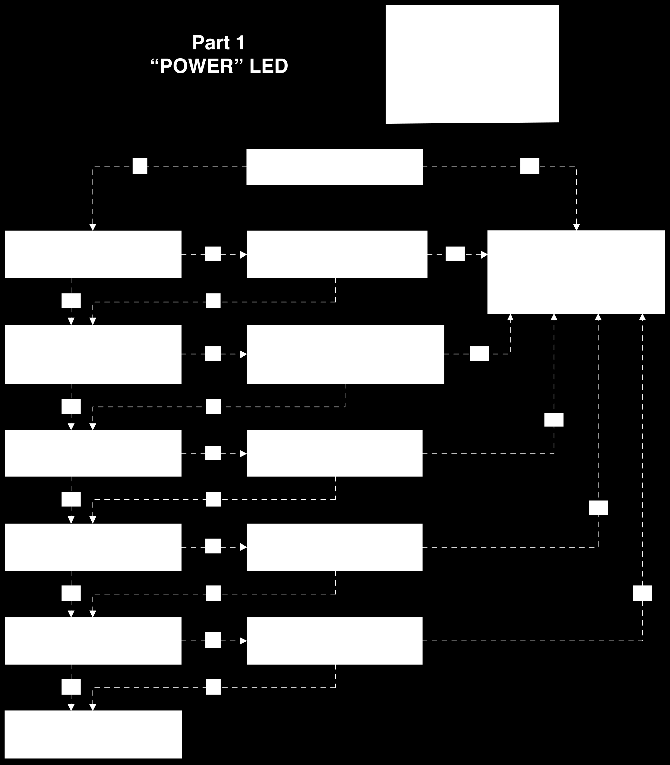
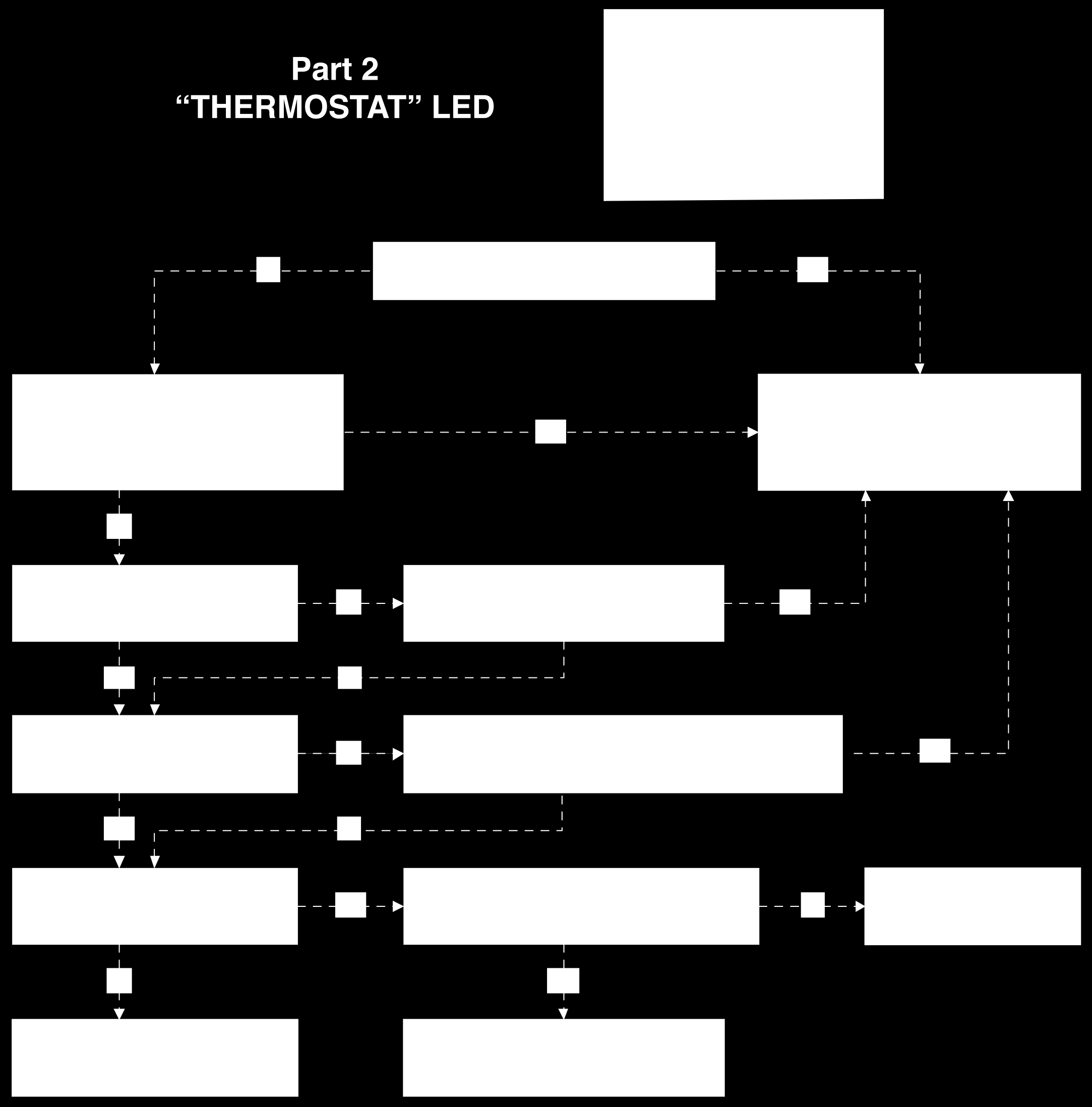
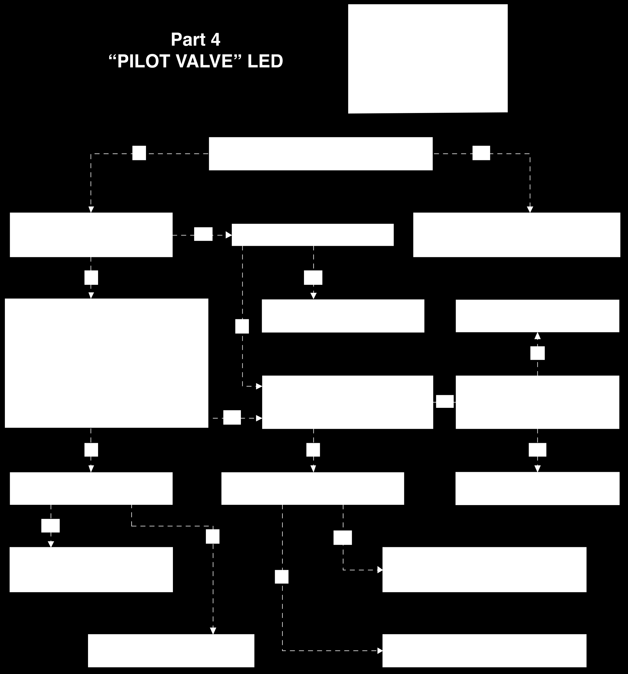
23 23 Part 5 - Troubleshooting Guide LED Diagnostic System This water heater is equipped with an LED (light emitting diode) diagnostic system, which is located in the black electrical box on the front left hand side of the water heater. The diagnostic system is designed to give the user or qualified service technician a visual indication of the operational status of the different parts of the water heater s control system. A fast look at the LED panel will identify where to begin troubleshooting a non-functioning water heater. A green light means that the sequence is operating properly and a red light means ongoing action or a problem with the sequence.
24 24
25 25

26 26
27 27

28 28
COMMERCIAL GAS-FIRED WATER HEATERS OWNER S MANUAL INSTALLATION AND OPERATING INSTRUCTIONS
 COMMERCIAL GAS-FIRED WATER HEATERS OWNER S MANUAL INSTALLATION AND OPERATING INSTRUCTIONS This water heater IS NOT design certified for installation in a manufactured (mobile) home or for installation
RESIDENTIAL GAS-FIRED WATER HEATERS OWNER S MANUAL INSTALLATION AND OPERATING INSTRUCTIONS
 RESIDENTIAL GAS-FIRED WATER HEATERS (EQUIPPED WITH FVIR TECHNOLOGY) OWNER S MANUAL INSTALLATION AND OPERATING INSTRUCTIONS This water heater IS NOT design certified for installation in a manufactured (mobile)
Instruction Manual for Residential Gas Water Heaters
 Instruction Manual for Residential Gas Water Heaters NOT FOR USE IN MANUFACTURED (MOBILE) HOMES GAMA certification applies to all residential gas water heaters with capacities of 20 to 100 gallons with
Instruction Manual for Residential Manufactured Home Gas Water Heaters
 Instruction Manual for Residential Manufactured Home Gas Water Heaters FOR USE ONLY IN MANUFACTURED HOMES GAMA certification applies to all residential gas water heaters with capacities of 20 to 100 gallons
Your safety and the safety of others are very important.
 NATURAL GAS TO PROPANE CONVERSION KIT 090 INSTALLATION INSTRUCTIONS FOR ALTITUDES 0 -,00 FT. ONLY PROPANE CONVERSION KIT SAFETY... INSTALLATION REQUIREMENTS... Tools and Parts... LP Gas Requirements...
2010 Residential Water Heater Replacement Check List
 2010 Residential Water Heater Replacement Check List The intent of this check list is to provide installers a general reference for the enforcement of code requirements in the Greater San Diego Area. This
CARING FOR YOUR WATER HEATER
 http://waterheatertimer.org/troubleshoot-rheem-tankless-water-heater.html Water Heater Inspections CARING FOR YOUR WATER HEATER Venting System (Direct Vent Only) The venting system should be inspected
INSTALLATION, OPERATION, AND SERVICE MANUAL RESIDENTIAL STORAGE TYPE GAS WATER HEATER
 INSTALLATION, OPERATION, AND SERVICE MANUAL RESIDENTIAL STORAGE TYPE GAS WATER HEATER THESE INSTRUCTIONS ARE INTENDED AS AN AID TO QUALIFIED SERVICE PERSONNEL FOR PROPER INSTALLATION, ADJUSTMENT AND OPERATION
LIGHT DUTY COMMERCIAL POWER VENT GAS-FIRED WATER HEATERS OWNER S MANUAL INSTALLATION AND OPERATING INSTRUCTIONS
 LIGHT DUTY COMMERCIAL POWER VENT GAS-FIRED WATER HEATERS OWNER S MANUAL INSTALLATION AND OPERATING INSTRUCTIONS This water heater IS NOT design certified for installation in a manufactured DANGER(mobile)
PURCHASED. IF YOU ARE UNSUCCESSFUL, PLEASE WRITE TO THE COMPANY LISTED ON THE RATING PLATE ON THE WATER HEATER.
 Instruction Manual COMMERCIAL GAS WATER HEATERS MODELS CG(N,L)075075, CG(N,L)075100 Series 300, 301 300 Maddox Simpson Parkway Lebanon, TN 37090 Phone: 615-889-8900 Fax: 615-547-1000 Technical Service
INSTALLATION AND OPERATIONS GUIDE FOR GRAND CANYON GAS LOG SYSTEMS
 INSTALLATION AND OPERATIONS GUIDE FOR GRAND CANYON GAS LOG SYSTEMS Installation and service must be provided by a qualified installer, service agency or gas supplier Grand Canyon Gas Logs, logs are made
INDIRECT WATER HEATER. Installation and Operating Instruction Manual
 INDIRECT WATER HEATER Installation and Operating Instruction Manual Maximum supply temperature to heat exchanger must not exceed 180 F (82 C). Safety Warning: Indirect water heaters are heat-producing
Instantaneous gas water heater
 Instantaneous gas water heater Models W 125...T1 installation operation maintenance The Bosch instantaneous water heater is a high efficiency, space saving answer to your water heating needs. All Bosch
Water Heaters. Commercial Gas. Use & Care Manual. With Installation Instructions for the Installer. Commercial 75 Gallon
 VACATION WARM COOLER A B C VERY HOT HOTTER! Warning: This water heater is not suitable for use in manufactured (mobile) homes! Commercial Gas Use & Care Manual With Installation Instructions for the Installer
Tankless Water Heater
 Tankless Water Heater USER S INFORMATION MANUAL Models WGRTNG199 / WGRTLP199 WGRTCNG199 / WGRTCLP199 NOTICE: Westinghouse reserves the right to make product changes or updates without notice and will not
ELECTRIC WATER HEATER INSTALLATION & OPERATING INSTRUCTION MANUAL
 ELECTRIC WATER HEATER A Spanish language version of these instructions is available by contacting the manufacturer listed on the rating plate. La version espanola de estas instruccions se puede obtener
Instruction Manual. Series 300, 301. For Your Safety AN ODORANT IS ADDED TO THE GAS USED BY THIS WATER HEATER.
 500 Tennessee Waltz Parkway Ashland City, TN 37015 Instruction Manual COMMERCIAL GAS WATER HEATERS MODELS BT-80, BT-100 Series 300, 301 INSTALLATION - OPERATION - SERVICE - MAINTENANCE - LIMITED WARRANTY
INSTALLATION & SERVICE MANUAL
 INSTALLATION & SERVICE MANUAL POWER VENTED GAS WATER HEATER If the information in these instructions is not followed exactly, a fire or explosion may result causing property damage, personal injury, or
COMMERCIAL GAS WATER HEATERS
 Instruction Manual COMMERCIAL GAS WATER HEATERS POWER VENTED GAS MODELS W/HOT SURFACE IGNITION MODEL BTX-80 SERIES 100 500 Tennessee Waltz Parkway Ashland City, TN 37015 Low Lead Content For Your Safety
Use & Care Manual. Electric Tankless Water Heaters. With Installation Instructions for the Installer AP15447 (10/10)
") Use & Care Manual With Installation Instructions for the Installer Electric Tankless Water Heaters The purpose of this manual is twofold: one, to provide the installer with the basic directions and recommendations
Use & Care Manual With Installation Instructions for the Installer Electric Tankless Water Heaters The purpose of this manual is twofold: one, to provide the installer with the basic directions and recommendations
GAS-FIRED COMMERCIAL WATER HEATER
 GAS-FIRED COMMERCIAL WATER HEATER WARNING: If the information in these instructions is not followed exactly, a fire or explosion may result causing property damage, personal injury or death. - Do not store
Phoenix Plus. Water Heater. Installation. Start-Up. Maintenance. Parts. Warranty. PHP Models*
 Phoenix Plus Water Heater Installation Start-Up Maintenance Parts Warranty PHP Models* * LP Denotes Propane Gas Operation This manual must only be used by a qualified installer / service technician. Read
GAS-FIRED WATER HEATER
 GAS-FIRED WATER HEATER A Spanish language version of these instructions is available by contacting the company listed on the rating plate. La version espanola de estas instrucciones se puede obtener al
Gas Water Heater with the Flame Guard Safety System Installation Instructions and Use & Care Guide
 Gas Water Heater with the Flame Guard Safety System Installation Instructions and Use & Care Guide Made under license from Flame Guard Water Heaters, Inc. R WARNING: If the information in these instructions
OPERATING, INSTALLATION AND SERVICE MANUAL
 OPERATING, INSTALLATION AND SERVICE MANUAL COMMERCIAL GAS WATER HEATER WITH FLUE DAMPER AND ELECTRIC IGNITION SYSTEM WITHOUT FAN MOTOR REQUIRES 120V A.C. POWER SUPPLY WARNING: If the information in these
PURCHASED. IF YOU ARE UNSUCCESSFUL, PLEASE WRITE TO THE COMPANY LISTED ON THE RATING PLATE ON THE WATER HEATER.
 Instruction Manual RESIDENTIAL GAS WATER HEATERS FOR USE ONLY IN MANUFACTURED HOMES GAMA certification applies to all residential gas water heaters with capacities of 20 to 100 gallons with input rating
Residential Gas Water Heater with the Flame Guard Safety System Installation Instructions and Use & Care Guide
 WARNING: If the information in these instructions is not followed exactly, a fire or explosion may result causing property damage, personal injury or death. Do not store or use gasoline or other flammable
Indirect Water Heaters
 Indirect Water Heaters Installation Start-Up Maintenance Parts Warranty For Residential and Commercial Use WI Models The surfaces of these products contacted by potable (consumable) water contain less
Electric Water Heater
 Electric Water Heater Operation and Installation Manual (LIMITED WARRANTY AND TANK REPLACEMENT POLICY) The following information should be noted at time of installation and retained for future reference.
RESIDENTIAL GAS WATER HEATERS
 Instruction Manual RESIDENTIAL GAS WATER HEATERS NOT FOR USE IN MANUFACTURED (MOBILE) HOMES GAMA certification applies to all residential gas water heaters with capacities of 20 to 100 gallons with input
Indirect-Fired Storage Water Heater Models WH-30 through WH-80 INSTALLATION AND OPERATING INSTRUCTIONS
 Indirect-Fired Storage Water Heater Models WH-30 through WH-80 INSTALLATION AND OPERATING INSTRUCTIONS Contents Page Ratings and Specifications..................... 2 Installation Requirements......................
Installation Instructions and Use & Care Guide
 WARNING: If the information in these instructions is not followed exactly, a fire or explosion may result causing property damage, personal injury or death. Do not store or use gasoline or other flammable
LIGHT DUTY COMMERCIAL ELECTRIC WATER HEATER INSTALLATION & OPERATING INSTRUCTION MANUAL
 LIGHT DUTY COMMERCIAL ELECTRIC WATER HEATER A Spanish language version of these instructions is available by contacting the company listed on the rating plate. La versión espãnola de estas instrucciones
PURCHASED. IF YOU ARE UNSUCCESSFUL, CALL THE TECHNICAL SUPPORT PHONE NUMBER SHOWN ON THE WATER HEATER LABELING.
 Instruction Manual COMMERCIAL GAS WATER HEATERS POWER VENT/POWER DIRECT VENT GAS MODELS WITH HOT SURFACE IGNITION Ashland City, TN 37015 www.hotwater.com For Your Safety AN ODORANT IS ADDED TO THE GAS
COMMERCIAL ELECTRIC WATER HEATER INSTALLATION & OPERATING INSTRUCTION MANUAL
 COMMERCIAL ELECTRIC WATER HEATER La A version Spanish espanola language de version estas of instrucciones these instructions se puede is available obtener al by escribirle contacting a la the fábrica company
Installation Instructions and Use & Care Guide
 Gas Water Heater with the Flame Guard Safety System Installation Instructions and Use & Care Guide Made under license from Flame Guard Water Heaters, Inc. R WARNING: If the information in these instructions
NOTE TO CONSUMER: PLEASE KEEP ALL INSTRUCTIONS FOR FUTURE REFERENCE.
 Superstor Ultra Indirect Fired Installation Water Heaters Start-Up Maintenance Parts Warranty For Residential and Commercial Use SSU Models The surfaces of these products contacted by potable (consumable)
RESIDENTIAL POWER VENT GAS-FIRED WATER HEATERS (EQUIPPED WITH FVIR TECHNOLOGY) OWNER S MANUAL INSTALLATION AND OPERATING INSTRUCTIONS
 OWNER S MANUAL INSTALLATION AND OPERATING INSTRUCTIONS") RESIDENTIAL POWER VENT GAS-FIRED WATER HEATERS (EQUIPPED WITH FVIR TECHNOLOGY) OWNER S MANUAL INSTALLATION AND OPERATING INSTRUCTIONS UG50-65(-59) Model This water heater IS NOT design certified for installation
RESIDENTIAL POWER VENT GAS-FIRED WATER HEATERS (EQUIPPED WITH FVIR TECHNOLOGY) OWNER S MANUAL INSTALLATION AND OPERATING INSTRUCTIONS UG50-65(-59) Model This water heater IS NOT design certified for installation
COMMERCIAL GAS WATER HEATER Glass-Lined Tank-Type Water Heater
 COMMERCIAL GAS WATER HEATER Glass-Lined Tank-Type Water Heater INSTALLATION OPERATION SERVICE MAINTENANCE Thank you for buying this energy efficient water heater. We appreciate your confidence in our products.
Residential Gas - FVIR Certified High Efficiency Condensing Power Direct Vent Water Heaters
 SCALD RISK INCREASES WITH HOTTER WATER To review or adjust tempture Step 1. Press the two temperature adjust buttons at the same time for 1 second. Step 2. To adjust, press COOLER or HOTTER button for
HVAC Code Requirements
 one and two family dwellings? Answer: SECTION 2001: GENERAL 2001.1 Air supply. Fuel-burning equipment shall be provided with a supply of air for fuel combustion, draft hood dilution and ventilation of
INSTALLATION AND OPERATING INSTRUCTION MANUAL
 POWERED DIRECT VENT GAS WATER HEATER A Spanish language version of these instructions is available by contacting the company listed on the rating plate. La version espanola de estas instrucciones se puede
CHAPTER 10 BOILERS, WATER HEATERS AND PRESSURE VESSELS
 CHAPTER 10 BOILERS, WATER HEATERS AND PRESSURE VESSELS SECTION 1001 GENERAL 1001.1 Scope. This chapter shall govern the installation, alteration and repair of boilers, water heaters and pressure vessels.
RESIDENTIAL ELECTRIC WATER HEATER OWNER S MANUAL INSTALLATION AND OPERATING INSTRUCTIONS
 RESIDENTIAL ELECTRIC WATER HEATER OWNER S MANUAL INSTALLATION AND OPERATING INSTRUCTIONS DANGER If the information in these instructions is not followed exactly, a fire or explosion may result causing
NOTICE: HTP reserves the right to make product changes or updates without notice and will not be held liable for typographical errors in literature.
 Phoenix Light Commercial INSTALLATION START-UP MAINTENANCE PARTS Models* PH76-50 / PH76-60 / PH76-80 *A suffix of LP denotes propane gas This manual must only be used by a qualified heating installer/service
Residential Gas Water Heaters. Residential 30, 38, 40 and 50 Gallon
 ! Warning: This water heater is not suitable for use in manufactured (mobile) homes! Use & Care Manual With Installation Instructions for the Installer Residential Gas Water Heaters The purpose of this
INSTALLATION, OPERATION, AND SERVICE MANUAL POWER VENT STORAGE TYPE GAS WATER HEATER MODELS PVG/PVCG
 INSTALLATION, OPERATION, AND SERVICE MANUAL POWER VENT STORAGE TYPE GAS WATER HEATER MODELS PVG/PVCG THESE INSTRUCTIONS ARE INTENDED AS AN AID TO QUALIFIED SERVICE PERSONNEL FOR PROPER INSTALLATION, ADJUSTMENT
Installation Instructions
 Installation Instructions Outdoor Tankless Water Heater Models GN75ENSRSA, GN94ENSRSA, GP94ENSRSA FOR OUTDOOR APPLICATIONS ONLY Questions? Call 888-HOTWTER (888.468.9837) or Visit our website at ge.com
INSTALLATION, OPERATING AND SERVICE INSTRUCTIONS
 INSTALLATION, OPERATING AND SERVICE INSTRUCTIONS HEAT-FLO HOT WATER STORAGE / BOOSTER TANKS MODELS 30-ST, 40-ST, 40L-ST, 60-ST, 60L-ST, 80-ST, 115-ST, 80-ST-C, 115-ST-C FOR SINGLE TANK INSTALLATIONS For
Water Heaters. Residential 30, 40 and 50 Gallon
 ! WARNING: This water heater is not suitable for use in manufactured (mobile) homes! Use & Care Manual With Installation Instructions for the Installer Gas Residential Water Heaters Model: HG Series, GG
Installation Instructions
 Installation Instructions Indoor Direct Vent Tankless Water Heater Models GN75DNSRSA, GN94DNSRSA, GP94DNSRSA FOR INDOOR APPLICATIONS ONLY Questions? Call 888.HOTWTER (888.468.9837) or Visit our website
SL280UHV SERIES GAS FURNACE WARNING
 2010 Lennox Industries Inc. Dallas, Texas, USA 506677 01 11/2010 Supersedes 506409 01 SL280UHV SERIES GAS FURNACE Litho U.S.A. FIRE OR EXPLOSION HAZARD. Failure to follow safety warnings exactly could
GAS SAFETY PRECAUTIONS
 GAS SAFETY PRECAUTIONS Instructions on what to do when a user smells gas can be obtained from the local gas supplier. These instructions must be posted in a prominent location where the unit is to be operated.
Residential 30, 38, 40, 50 and 60 Gallon
 ! WARNING: This water heater is not suitable for use in manufactured (mobile) homes! Use & Care Manual With Installation Instructions for the Installer Residential Gas - FVIR Certified Water Heaters Residential
Water Heaters. Residential 30, 40 and 50 Gallon
 Residential 30, 40 and 50 Gallon Use & Care Manual With Installation Instructions for the Contractor Gas Residential Water Heaters Model: HG Series, GG Series, GP Series, PG Series, SG Series, SG Series
Water Heater Safety Tips
 Instruction Manual for Light Duty Commercial Power Direct Vent Gas Water Heaters ALL TECHNICAL AND WARRANTY QUESTIONS: SHOULD BE DIRECTED TO THE LOCAL DEALER FROM WHOM THE HEATER WAS PURCHASED. IF YOU
Arapahoe County Residential Water Heater Installation and Inspection Guide
 Arapahoe County Residential Water Heater Installation and Inspection Guide The attached handout is designed to be a general permit submittal and inspection guide covering most installation instances, however
Everlast Electric Water Heater
 Everlast Electric Water Heater INSTALLATION START-UP MAINTENANCE PARTS Everlast Water Heater Models EV-6 / EV-12 / EV-20 / EV-30 EV-30LB / EV-45LB / EV-50 / EV-80 California Proposition 65 Warning: This
WHAT TO DO IF YOU SMELL GAS
 Installation Instructions and Use & Care Guide RESIDENTIAL GAS WATER HEATERS HIGH EFFICIENCY ATMOSPHERIC VENT GAS WATER HEATER (FLAMMABLE VAPOR IGNITION RESISTANT) FOR SPACE HEATING AND POTABLE WATER HEATING
CHAPTER 5 WATER HEATERS
 PlumbingCode06_ch05 5/29/06 8:12 AM Page 1 CHAPTER 5 WATER HEATERS Water heaters are only a small portion of a plumbing system, but they are important, and they can be dangerous. Many plumbers take water
DRYER VENTING SPECIFICATIONS DRYER SAFETY
 DRYER VENTING SPECIFICATIONS Table of Contents DRYER SAFETY...1 INSTALLATION REQUIREMENTS...4 Venting Requirements...5 DRYER INSPECTION AND CLEANING...7 Frequency of Exhaust System Cleaning...7 Inspecting
COMMERCIAL GAS WATER HEATERS
 Instruction Manual COMMERCIAL GAS WATER HEATERS POWER VENTED GAS MODELS W/HOT SURFACE IGNITION MODEL SHE 50 76N SERIES 100 500 Tennessee Waltz Parkway Ashland City, TN 37015 Low Lead Content For Your Safety
Please keep this manual for f uture reference.
 GAS WATER/AGUA Congratulations! You've just purchased a new Marey Portable tankless water heater and will soon begin to enjoy the benefits of going tankless. Take the time to thoroughly read and understand
Installation Manual DIAPHRAGM WELL TANK
 Installation Manual DIAPHRAGM WELL TANK IN-LINE SERIES: 2-5 & 7 GALLON VERTICAL SERIES: 14-20-25-32-36-52-65-86-96-119 GALLON HORIZONTAL SERIES: 7-14 & 20 GALLON NO LEAD NO LEAD: The weighted average of
RESIDENTIAL GAS WATER HEATERS
 Instruction Manual RESIDENTIAL GAS WATER HEATERS NOT FOR USE IN MANUFACTURED (MOBILE) HOMES For Your Safety AN ODORANT IS ADDED TO THE GAS USED BY THIS WATER HEATER. ALL TECHNICAL AND WARRANTY QUESTIONS:
Light Duty Commercial Electric Water Heaters
 Use and Care Manual Installation Start-Up Maintenance Parts Warranty Light Duty Commercial Electric Water Heaters This manual must only be used by a qualified installer / service technician. Read all instructions
Installation Instructions and Use & Care Guide
 WARNING: If the information in these instructions is not followed exactly, a fire or explosion may result causing property damage, personal injury or death. Do not store or use gasoline or other flammable
Propane Conversion Kit PROPANE CONVERSION KIT INSTALLATION MANUAL
 Propane Conversion Kit Supersedes: 145.25-IOM2 (708) Form 145.25-IOM2 (908) PROPANE CONVERSION KIT INSTALLATION MANUAL "LPKIT " - PROPANE CONVERSION KIT Kits are available for field conversion from natural
commercial gas water heaters
 Instruction Manual commercial gas water heaters www.americanwaterheater.com American Water Heater Johnson City, TN 37605 MODELS BCG3 & ABCG3 SERIES 118/119 INSTALLATION - OPERATION - SERVICE - MAINTENANCE
TANKLESS WATER HEATER USE AND CARE MANUAL
 WARNING: If the information in these instructions is not followed exactly, a fire or explosion may result, causing death, personal injury, or property damage. For Your Safety! Do not store or use gasoline
GROWTH MANAGEMENT DEPARTMENT 201 SE 3 rd ST, (Second Floor), Ocala, FL 34471 (352) 629-8421; FAX: (352) 629-8264
, Ocala, FL 34471 (352) 629-8421; FAX: (352) 629-8264") BUILDING CODE GUIDELINE FOR MECHANICAL INSPECTIONS Building Code compliance is the obligation of design professionals and/or contractors. Plan Review and Inspection Guidelines are intended to be used by
BUILDING CODE GUIDELINE FOR MECHANICAL INSPECTIONS Building Code compliance is the obligation of design professionals and/or contractors. Plan Review and Inspection Guidelines are intended to be used by
NOTE! READ INSTRUCTIONS FULLY BEFORE INSTALLING OR OPERATING.
 INSTALLATION AND OPERATION GUIDE FOR HARGROVE GAS LOGS PROPANE GAS ADEQUATE FIREPLACE VENTILATION IS REQUIRED FOR SAFETY. GAS LOGS MUST BE INSTALLED BY PERSONNEL QUALIFIED FOR INSTALLING GAS APPLIANCES.
COMMERCIAL GAS WATER HEATER
 Owner s Manual COMMERCIAL GAS WATER HEATER FOR POTABLE WATER HEATING ONLY NOT SUITABLE FOR SPACE HEATING NOT FOR USE IN MOBILE HOMES MODEL NO. CAPACITY 153.338074 74 Gallon (280 Liter) 153.338004 98 Gallon
On-Demand Water Heater Installation Manual and Owner s Guide
 On-Demand Water Heater Installation Manual and Owner s Guide ANSI Z21.10.3 and CSA 4.3 540 (T-H3) model only 240 Indoor (T-H3J-DV) 340 Indoor (T-H3S-DV) 540 Indoor (T-H3-DV) Models 240 Outdoor (T-H3J-OS)
Installation Operation Maintenance
 Installation Operation Maintenance 2009 Heat Transfer Products, Inc. Phoenix Evolution Water Heater Models* PHE130-55 / PHE199-55 PHE130-80 / PHE199-80 PHE130-119 / PHE199-119 *A suffix of LP denotes propane
NOTE TO CONSUMER: PLEASE KEEP ALL INSTRUCTIONS FOR FUTURE REFERENCE.
 INSTALLATION START-UP MAINTENANCE PARTS Water Heater Models* UGC55S-100 / UGC55S-130 / UGC55S-160 / UGC55S-199 UGC80S-100 / UGC80S-130 / UGC80S-160 / UGC80S-199 UGC120S-100 / UGC120S-130 / UGC120S-160
RESIDENTIAL POWER VENT GAS-FIRED WATER HEATERS (EQUIPPED WITH FVIR TECHNOLOGY) OWNER S MANUAL INSTALLATION AND OPERATING INSTRUCTIONS
 OWNER S MANUAL INSTALLATION AND OPERATING INSTRUCTIONS") RESIDENTIAL POWER VENT GAS-FIRED WATER HEATERS (EQUIPPED WITH FVIR TECHNOLOGY) OWNER S MANUAL INSTALLATION AND OPERATING INSTRUCTIONS PV1 Model only This water heater IS NOT design certified for installation
RESIDENTIAL POWER VENT GAS-FIRED WATER HEATERS (EQUIPPED WITH FVIR TECHNOLOGY) OWNER S MANUAL INSTALLATION AND OPERATING INSTRUCTIONS PV1 Model only This water heater IS NOT design certified for installation
PURCHASED. IF YOU ARE UNSUCCESSFUL, CALL THE TECHNICAL SUPPORT PHONE NUMBER SHOWN ON THE WATER HEATER LABELING.
 Instruction Manual RESIDENTIAL GAS WATER HEATERS POWER VENT/POWER DIRECT VENT GAS MODELS WITH HOT SURFACE IGNITION Complies with SCAQMD Low NOx Rule 1146.2 Ashland City, TN 37015 www.hotwater.com Low Lead
INSTALLATION & MAINTENANCE MANUAL TURBOPOWER GAS, OIL & GAS/OIL WATER HEATER
 INSTALLATION & MAINTENANCE MANUAL TURBOPOWER GAS, OIL & GAS/OIL WATER HEATER Installation and service must be performed by a qualified service installer, service agency or the gas supplier. Oil Gas/Oil
Installation Instructions and Use & Care Guide
 This manual covers model numbers: United States Canada PG10* 34-100-2NV or 2PV PG10* 34-130-2NV or 2PV PG10* 50-130-2NV or 2PV PG10* 34-150-2NV or 2PV PG10* 50-175-3NV or 3PV PG10* 50-199-3NV or 3PV PG10*
PURCHASED. IF YOU ARE UNSUCCESSFUL, CALL THE TECHNICAL SUPPORT PHONE NUMBER SHOWN ON THE WATER HEATER LABELING.
 Instruction Manual RESIDENTIAL GAS WATER HEATERS POWER VENT/POWER DIRECT VENT GAS MODELS WITH HOT SURFACE IGNITION MODEL GDHE 50 SERIES 124/125 Complies with SCAQMD Low NOx Rule 1146.2 Ashland City, TN
Installation Operation & Maintenance Manual
 www.montigo.com Operation & Maintenance Manual Check local codes and read all instructions prior to installation. EDVPV BF-Series Wall SS Power Gas Fireplace Vent System EDVPV47 EDVPV58 Warning: Improper
LAKE COUNTY ANIMAL SERVICES EXPANSION SECTION 15459
 SECTION 15459 PART 1 - GENERAL 1.1 RELATED DOCUMENTS: A. Drawings and general provisions of Contract, including General and Supplementary Conditions and Division-1 Specification sections, apply to work
Seaward Products OWNER S MANUAL WATER HEATERS. Serial Number:
 Seaward Products WATER HEATERS OWNER S MANUAL Serial Number: IMPORTANT SAFETY INSTRUCTIONS WARNING When using electrical appliances, basic safety precautions to reduce the risk of fire, electrical shock,
Commercial Gas Water Heaters
 UP TO 96% THERMAL EFFICIENCY, DIRECT-VENT FEATURES TM BTH-120 through BTH-500 The A. O. Smith Cyclone Xi family of products represents the industry s most technologically advanced commercial water heaters.
Do not store or use gasoline or other flammable vapors and liquids in the vicinity of this or any other appliance.
 Condensing Water Heater Operation Manual Model NPE-180A/ 210A/ 240A NPE-180S/ 210S/ 240S * Lead Free Keep this manual near this water heater for future reference whenever maintenance or service is required.
INSTALLATION INSTRUCTIONS
 PRODUCT LITERATURE Lennox Industries Inc. Dallas, Texas INSTALLATION INSTRUCTIONS GWB8-042IE-2, GWB8-075IE-2 GWB8-112IE-2, GWB8-150IE-2 GWB8-187IE-2, GWB8-225IE-2 GAS FIRED BOILER RETAIN THESE INSTRUCTIONS
ASX7-4-IOM-7 J30-08579
 INSTALLATION INSTRUCTIONS 4" COMBUSTION AIR INLET KIT TUBULAR GAS FIRED DIRECT SPARK PROPELLER UNIT HEATERS UNIT CONVERSION & CATEGORY III VENTING FOR SEPARATED COMBUSTION For 30,000 to 75,000 BTU/HR SUPPLEMENT
Power Vented Gas Water Heater Installation Instructions and Use & Care Guide
 Flammable Vapor Ignition Resistant Compliant Power Vented Gas Water Heater Installation Instructions and Use & Care Guide : If the information in these instructions is not followed exactly, a fire or explosion
OPERATING, INSTALLATION AND SERVICE MANUAL STORAGE TYPE GAS WATER HEATER 95001 12/94
 OPERATING, INSTALLATI AND SERVICE MANUAL STORAGE TYPE GAS WATER HEATER 95001 12/94 : This information in these instructions must be followed exactly. Improper installation, adjustment, alteration, service
!"" #$% "!&' ( ( ) *
 *") !"" #$% "!&' (( ) * G Whiz Gas Popper Instruction Manual Model #5908 Part No. 74874 Revised October 1997 Cincinnati, OH 45241-4807 USA GAS SAFETY PRECAUTIONS Instructions on what to do when a user smells
!"" #$% "!&' (( ) * G Whiz Gas Popper Instruction Manual Model #5908 Part No. 74874 Revised October 1997 Cincinnati, OH 45241-4807 USA GAS SAFETY PRECAUTIONS Instructions on what to do when a user smells
T-KJr. Instantaneous Water Heater Installation Manual and Owner s Guide
 T-KJr. Instantaneous Water Heater Installation Manual and Owner s Guide WARNING This product must be installed and serviced by a licensed plumber, a licensed gas fitter, or a professional service technician
NAVIEN AMERICA INC. 17855 FITCH AVENUE
 Navien America Inc. Specification Details for the Navien models: CC-240 CC-240A For Potable Water Heating and Space Heating NAVIEN AMERICA INC. 17855 FITCH AVENUE IRVINE, CALIFORNIA, USA 92614 Toll Free:
Cooling Capacity CFM range @.5 in. w.c. (125 Pa)
") N8MXL Product Specifications 80% ECM Single Stage Heating Furnace EASIER TO SELL 80% AFUE Flame roll out sensors standard Category I venting Blocked vent switch 24 VAC humidifier terminal Electronic air
N8MXL Product Specifications 80% ECM Single Stage Heating Furnace EASIER TO SELL 80% AFUE Flame roll out sensors standard Category I venting Blocked vent switch 24 VAC humidifier terminal Electronic air
36G22, 36G23, 36G24 & 36G52 36J22, 36J23, 36J24 & 36J52 DSI and HSI Single Stage Combination Gas Valve
 Operator: Save these instructions for future use! FAILURE TO READ AND FOLLOW ALL INSTRUCTIONS CAREFULLY BEFORE INSTALLING OR OPERATING THIS CONTROL COULD CAUSE PERSONAL INJURY AND/OR PROPERTY DAMAGE. DESCRIPTION
INDIRECT WATER HEATER
 INDIRECT WATER HEATER INSTALLATION AND OPERATING INSTRUCTIONS Read and understand these instructions thoroughly before starting TABLE OF CONTENTS I) Introduction............................2 II) Safety.................................2
Installation Manual DIAPHRAGM WELL TANK
 Installation Manual DIAPHRAGM WELL TANK Safety Instructions Installation Warranty IN-LINE SERIES: 2-5 & 7 GALLON HORIZONTAL SERIES: 7-14 & 20 GALLON VERTICAL SERIES: 14-20-32-36-52-86-96-119 GALLON KEEP
T-K3 Instantaneous Water Heater Installation Manual and Owner s Guide
 T-K3 Instantaneous Water Heater Installation Manual and Owner s Guide WARNING This product must be installed and serviced by a licensed plumber, a licensed gas fitter, or a professional service technician.
OWNER S MANUAL FORCE 10 MARINE COMPANY 23080 HAMILTON ROAD RICHMOND, BC CANADA V6V 1C9 TEL: (604) 522-0233 FAX: (604) 522-9608
 522-0233 FAX: (604) 522-9608") Electric Water Heater OWNER S MANUAL FORCE 10 MARINE COMPANY 23080 HAMILTON ROAD RICHMOND, BC CANADA V6V 1C9 TEL: (604) 522-0233 FAX: (604) 522-9608 If your water Heater is Damaged or you have questions
Electric Water Heater OWNER S MANUAL FORCE 10 MARINE COMPANY 23080 HAMILTON ROAD RICHMOND, BC CANADA V6V 1C9 TEL: (604) 522-0233 FAX: (604) 522-9608 If your water Heater is Damaged or you have questions
USER S INFORMATION MANUAL
 USER S INFORMATION MANUAL UPFLOW, DOWNFLOW, UPFLOW/HORIZONTAL & HORIZONTAL ONLY INDUCED DRAFT GAS FURNACES Recognize this symbol as an indication of Important Safety Information If the information in this