Tooway KU-band Satellite Terminal Handbook
|
|
|
- Elisabeth Richardson
- 10 years ago
- Views:
Transcription
1 Tooway KU-band Satellite Terminal Handbook Eutelsat Multimedia Department System Integration Team Version 4.5 Nov

2 1 SYSTEM AND SERVICE OVERVIEW BASIC TECHNICAL DATA TERMINAL DATA ADVANTAGE VERSUS OTHER EXISTING SYSTEMS THE EUROBIRD 3 SATELLITE AT 33 EAST KU BAND DOWNLINK COVERAGE SPOT A KU BAND DOWNLINK COVERAGE SPOT C TRANSPONDERS EUROBIRD THE TOOWAY KU BAND TERMINAL TOOWAY KU-BAND OUTDOOR UNIT SATELLITE ANTENNA LNB AND BUC The cables The Connectors THE SATELLITE MODEM CONNECTION OF THE MODEM MODEM FRONT PANEL INDICATORS SAFETY PRECAUTIONS ODU AND ANTENNA INSTALLATION FOR ASC 100 ANTENNA CONTENTS OF PACKAGE BUC ANTENNA ARMS ANTENNA AND ANTENNA SUPPORT A MOUNTING OF ANTENNA ON SUPPORT B WALL MOUNT ODU and Antenna Installation FOR VISIOSAT ANTENNA Content of package Outdoor Unit Invacom Visiosat feed Apersat OMT - Zinwell LNB - USM BUC Visiosat feed Invacom OMT/LNB Invacom BUC Visiosat feed Invacom OMT/LNB USM BUC Assembly of AZ/EL mount Assembly of the feed arm and ODU ANTENNA POINTING OF TOOWAY TERMINAL PRESUMPTIONS AND PREPARATION IMPOTANT PLEASE NOTE PROCEDURE 1 OR PROCEDURE2? ADJUST SETTINGS OF THE SATELLITE METER TO LNB LO FREQUENCIES PROCEDURE GET YOUR POINTING ANGLES OF EB POLARIZATION ANGLE ELEVATION ANGLE... 57

3 8.3 PROCEDURE 2 - POINTING OF THE ANTENNA TO EB3 SPOT A OR D (LOW BAND LNB) GET YOU REFERENCE TV CHANNELS ADJUST SETTINGS OF THE SATELLITE METER TO LNB LO FREQUENCIES ROUGH POINTING POINTING OPTIMISATION POINTING OF THE ANTENNA TO EB3 SPOT C (HIGH BAND LNB) GET YOU REFERENCE TV CHANNELS ADJUST SETTINGS OF THE SATELLITE METER TO LNB LO FREQUENCIES ROUGH POINTING POINTING OPTIMISATION VERTICA POLARIZATION.80 9 THE CARRIER ACQUISITION PROCESS AND LOG IN TO THE NETWORK PRE ADJUSTED PARAMETERS BY SKYLOGIC SEARCHING FOR THE CHANNELS AND REGISTERING THE SM DOWNSTREAM SEARCH UPSTREAM SEARCH TROUBLE SHOOTING SATELLITE TERMINAL PWR INDICATOR DOES NOT LIGHT RX INDICATOR 1FLASH CONTINUOUSLY => TERMINAL NOT ACQUIRING DOWNSTREAM RX INDICATOR 2FLASH CONTINUOUSLY=> DOWNSTREAM ACQUIRED, TRYING TO RANGE TX INDICATOR - DOES NOT FLASH DURING UPSTREAM TRANSMISSION LAN INDICATOR DOES NOT FLASH OR LIGHT RX INDICATOR ON BUT CANNOT ACCESS INTERNET RX INDICATOR FLASHING VERY FAST => TERMINAL BOOT FAILURE TERMINAL SELF ACTIVATION PRE-EGISTRATION SELF ACTIVATION PROCEDURE The satellite terminal activation interface Step Step 2 and step Step LIST OF LITERATURE USED:

4 RELEASE NOTES : 4.3->4.5 (2/11/09) - add Visiosat antenna (part 7) - add 3 feed/lnb/buc (part 7.2.1,7.2.2,7.2.3) with photos - rebuild the summary Ajout de The maximum voltage drop between the modem and antenna is 6.7vdc on both Rx and Tx page 14 Changement dans l ordonnancement des photo page 33 et 34 Version 4.2 change compare to version 4.0 : 12/01/09 - page picture presentation - page 43 add procedure 1 description - page 46 pictures - page 50 add some precisions - page 52 add procedure 2 description - page 82 and folowings, add the 'self activation procedure' document from skylogic Version 4 : 02/10/08 4

5 1 System and service overview Tooway is based on the Surfbeam Product manufactured by ViaSat, which is built on the DOCSIS standard for broadband cable connections: Data Over Cable System Interface Standard Open standard in wide use today, > 70M subscribers worldwide Continuously being upgraded to add more value added services Designed for very large networks Satellite Modem (SM) Utilise Cable Modem and DTH Set-Top-Box chipsets Replace cable system physical (PHY) layer with satellite compatible PHY (modulation & coding) Satellite Modem Termination System (SMTS) (Hub) Utilise Cable Modem Termination System (CMTS) products Replace cable system PHY layer with satellite compatible PHY Add dynamically variable coding and modulation Add fade mitigation algorithms to maximize throughput Modified scheduler for use in satellite environment Skylogic Network operation center Turin SkyPark Network > 14 hubs on 8 satellites > Connection to Turin/Milan/Paris POP > 2 Ka band antennas (W3A Africa and HB6 multiple transponders and spots) 24h/7days service 5
 products Replace cable system PHY layer with satellite compatible PHY Add dynamically variable coding and modulation Add fade mitigation algorithms to maximize throughput")
6 2 Basic technical data 2.1 Terminal Data Downstream: Symbol Rate: 5 to 30 Mbauds Code Point Options: QPSK ½, 8PSK 2/3 Upstream Symbol Rate: 160, 320, 640, 1280, 2560 kbps (QPSK ½ and 3/4) Fade Mitigation Full upstream & downstream fade mitigation process SM FWD and RTN link multi rate SMTS Multi-State Upstream Scheduler Manual Hot Swap Redundancy FWD and RTN link multi rate Multicast enabled 6

7 2.2 Advantage versus other existing systems Multi-Rate PHY Advantage > Terminals in Clear-Sky receive packets at high Information Rate > Transmissions to terminals experiencing fade are automatically sent at a more robust code point > Large throughput advantage, since clear sky conditions usually prevail (typ. 95+%) > Static PHY systems (e.g. DVB-S) must transmit at the more robust code point at all times to achieve desired availability SurfBeam Multi-Rate Multi-Rate PHY PHY 8PSK 5/6 Turbo 68.1 Mbps Increasing Fade Causes Auto Adjustment to 8PSK 2/3 Turbo 56.7 Mbps Increasing Fade Causes Auto Adjustment to QPSK 1/2 Turbo 28.2 Mbps SurfBeam SurfBeam Throughput: Throughput: Mbps Mbps Averaged over Year Averaged over Year Fade<1 db 96% of Year 1 db<fade<3.8 db 3.7% of Year 3.8 db<fade<7.2 db 0.3% of Year DVB DVB --S (Static (Static PHY) PHY) QPSK 1/2 CEVD 27.6 Mbps No Adjustment Possible QPSK 1/2 CEVD 27.6 Mbps No Adjustment Possible QPSK 1/2 CEVD 27.6 Mbps DVB-S DVB-S Throughput: Throughput: Mbps Mbps Averaged over Year Averaged over Year Page 5 Paris, 14/03/2007 CONFIDENTIAL 7
 PHY) QPSK 1/2 CEVD 27.")
8 3 The Eurobird 3 satellite at 33 East 3.1 Ku Band downlink coverage Spot A 8

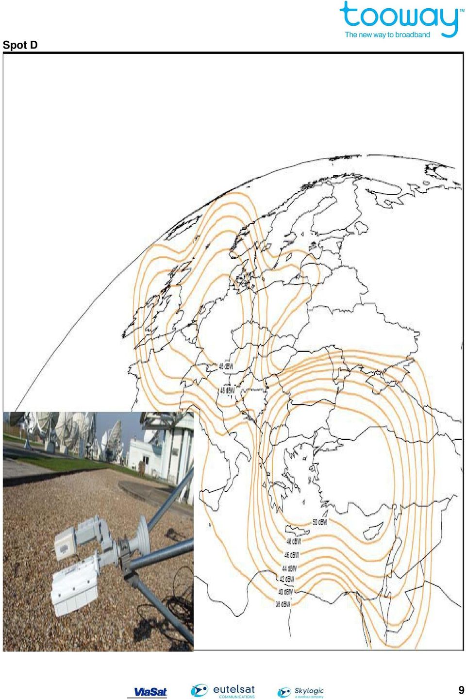
9 Spot D 9
10 3.2 Ku Band downlink coverage Spot C 10

11 3.3 Transponders Eurobird C 1 C 2 C 3 C 4 C 5 C 6 CR BR B1 B2 B3 B4 B5 B6 POL X AR DR A 1 A2 A3 D1 D2 D3 POL Y AR DR A 1 A2 A3 D1 D2 D3 POL X CR BR B1 B2 B3 B4 B5 B6 C 1 C 2 C 3 C 4 C 5 C 6 POL Y

12 4 The Tooway Ku band terminal 4.1 Tooway Ku-band Outdoor unit Satellite Antenna The antenna is manufactured by 12

13 4.1.2 LNB and BUC 2 Watt US Monolithics BUC Zinwell LNB Complete ODU electrics with OMT and Transmit reject filter 13

14 14

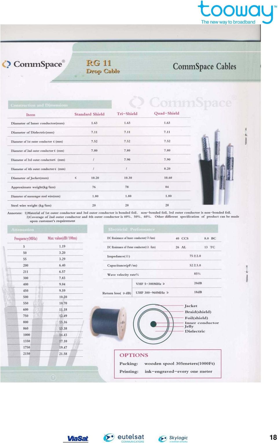
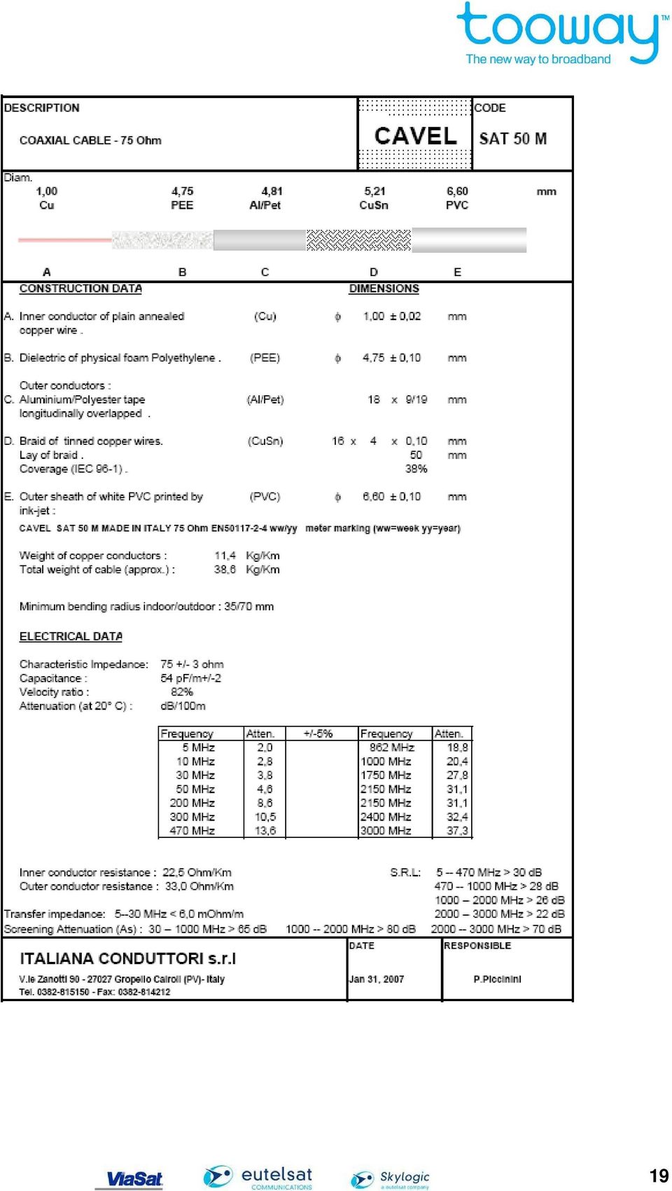
15 4.1.3 The cables Two factors are important: Electrical DC resistance (Ohm) for the power support from Satellite Modem to BUC Maximum value (inner connector plus outer braid) = 2.27 Ohms The maximum voltage drop between the modem and antenna is 6.7vdc on both Rx and Tx. This results to a maximum cable length between IDU and ODU of 30 m using RG59 Cable 50 m using RG 6 Cable 100 m using RG 11 Cable. What follows are examples of the cables that meet the required specifications 15

16 16

17 17

18 18
19 19
20 4.1.4 The Connectors Ensure connectors are compatible with cable (check with cable suppliers) You must use compression connectors for any exterior connection. These compression connectors ensure the integrity of the cable. IF Cables OUTDOOR Cablecon and Stirling compression connectors RG 6 connectors INDOOR Most crimp connectors RG 11 F163 Cablecon FM 32 and Cablecon and Stirling compression connectors Page 47 Paris, 11/09/07 Terminal Configuration(s) 20

21 21
22 The Satellite Modem Power: Ethernet LAN: RX In: TX Out: input + 30 V DC from Power Supply 10/100 base T Ethernet, RF 45 Jack L Band Input MHz Type F 75 Ohm female connector, provides power to LNB 24V 250 ma L Band Output MHz Type 75 Ohm female connector, provides DC power to BUC 30 V, 1.78 A Connection of the Modem 22
23 Modem Front panel Indicators 23
24 5 Safety Precautions 24
25 6 ODU and Antenna Installation for ASC 100 Antenna Site selection Important: mark the TX cable on both ends so you do not swap cable between modem and ODU. Select the antenna site making sure that you have no obstructions in the line of sight (the line between the antenna and the satellite position). You should ensure that there are no trees or other bushes that could in the future obstruct the line of sight. Install the antenna mount (Wall mount or non-penetrating mount) according to local security regulations and the requirements of the local environment. (Condition of walls or ground) Try to choose a position that protects the antenna from excess wind or weather (snow) as these could reduce the effectiveness of the antenna Make sure the antenna mast or pole which the antenna sits on is vertical. This is necessary when adjusting the elevation Place the antenna AZ/EL mount on the antenna pole or mast and fix the antenna so that it can be moved in Azimuth. 25
26 6.1 Contents of Package 26
27 The modem and its power supply Zinwell LNB with Circular rubber joint and screw 27
28 6.2 BUC BUC with joint and screws 28
29 ODU with OMT and wave guide It is very important to put in place the rubber circular joints 29
30 6.3 Antenna and antenna support Insert 4 x bolts as shown below with washers 30
31 31
32 6.4 Antenna arms Antenna arms and Feed horn bracket 32
33 Antenna arms from another angle 33
34 Antenna arms next to parabol You must make sure the bottom arm sits in fully in hole 34
35 The grub screw for the bottom arm must be unscrewed to allow the arm to fully enter its mounting hole. Then the grub screw must be tightened ontoi the arm 35
36 6.5.A Mounting of antenna on support Different elements for the support 36
37 Antenna mounting 6.5.B Wall mount 37
38 How to adjust antenna in Azimuth (Left and right) and Elevation 2 x Azimuth bolts which also secure antenna to pole or mount 4 x Elevation bolts which secure antenna when you have found satellite 1 x Elevation adjustment bolt 38
39 7 ODU and Antenna Installation for Visiosat Antenna SMC 90 The Tooway terminal with the visiosat antenna can be delivered with 3 different configurations of the OutDoor electronic unit. a/ Visiosat feed Apersat OMT - Zinnvell LNB - USM BUC b/ Visiosat feed Invacom OMT/LNB Invacom BUC c/ Visiosat feed Invacom OMT/LNB USM BUC The first part describes the assembly of the outdoor electronics. Please identify first which configuration is actually delivered. 7.1 Content of package 7.2 Assembly OutDoor electronic Unit Visiosat feed Apersat OMT - Zinwell LNB - USM BUC ODU material as it arrives Assembly Feed and OMT with 6 bolts 39
40 Important! Insert Rubber ring at feed, LNB and BUC Tighten the six bolts with a special Allen key Mount LNB and BUC Put rubber ring at BUC 40
41 Make sure that wave guides of BUC and OMT are in the same direction Fix BUC with 4 short bolts use Allen key with a ball Make sure that wave guides of LNB and OMT are in the same direction and put rubber ring to LNB Mout LNB using short bolts Fix the LNB The ODU is ready 41
42 7.2.2 Visiosat feed Invacom OMT/LNB Invacom BUC Assembly Out door Unit Invacom OMT/LNB, Invacom Buc Put rubber-ring to seal joint between BUC and OMT 42
43 Fixation of OMT/LNB with BUC Put rubber-ring to seal joint between OMT and Feed 43
44 The complet Out Door Unit 44
45 7.2.3 Visiosat feed Invacom OMT/LNB USM BUC Tools for assembly and final ODU configuration Mounting the Feed to the OMT/LNB 45
46 7.3 Assembly of Antenna Mounting the BUC to the OMT/LNB 46
47 Assembly of AZ/EL mount with reflector 47
48 7.4 Assembly of the feed arm and ODU Mounting the feed arm to the reflector Mounting of the shots to hold the feed arm 48
49 49
50 The complete ODU and antenna 50
51 8 Antenna pointing of Tooway terminal 8.1 Presumptions and Preparation The following 2 procedures are for installers who have: 1. already successfully pointed television satellite Antennas to Hot Bird 13 east or similar positions 2. have a satellite meter able to detect and identify digital TV carriers in DVB standard. Examples: Horizon (USB plus), Promax (TV explorer), Emitor (Satlook) Impotant please note : 1. No TV channels on EB 3, pointing is to data carriers in DVB standard. 2. Carrier optimisation is only possible using the carrier level and the DVB carrier BER reading for Polarisation. 3. The Tooway terminal LNB is single polarisation, single band, just one Voltage 18 V, no 22 Khz, no DiSEcQ. 4. The LNB is not a universal LNB, its LO frequency is either 10 GHz in low band or 11.3 GHz in high band, not switchabel. Change of frequency means change of LNB. 5. For the different spots of EB3 the following LNB s are required: EB3 Spot A, D => low band LNB 10 GHz LO frequency EB3 Spot C => high band LNB, 11.3 GHz LO frequency 6. Polarisation is to adjust manually and with an accuracy of 1. The ODU is normally not straight in a horizontal or vertical position but need to be rotated for polarization optimisation. 7. The procedure will use the DVB carrier of the Skylogic D Star service for pointing as the Tooway carrier is not a DVB carrier and it more difficult to optimise. If the terminal points optimum to the relevant D Star carrier it points automatically optimal to the Tooway carrier on the same spot Procedure 1 or procedure 2? Procedure 1 is for installers used to working from the elevation angle needed to find the correct satellite. If you are installers and you have the habits to pointed television satellite Antennas to Hot Bird 13 east or similar positions, this procedure is simpler and quicker than the procedure 2. 51
52 If you never pointed television satellite Antennas to Hot Bird 13 east or similar positions or if you want a maximum precision, procedure 2 is better than procedure 1 for you Adjust settings of the satellite meter to LNB LO frequencies Usually satellite meters are pre-programmed for universal LNB s with LO frequencies 9.75 GHz for low band and 10.6 GHz for high band so the display shows the satellite downlink frequency. 1. Change the settings of the satellite meter to LNB Lo frequencies 10 GHz for low band and 11.3 GHz for high band If not possible 2. Change the setting of the satellite meter to read the IF frequency directly. LNB LO frequency = If it is not possible to change the LNB LO frequency setting please assume a 9.75 and 10.6 GHz presetting. In this case, it is necessary to calculate the correct frequencies as follows: Displayed frequency on sat meter = Real downlink frequency MHz for low band and Displayed frequency on sat meter = Real downlink frequency MHz for high band We have defined two procedures to antenna pointing. The first is based on an elevation and polarization angle calculated from a website. The second approach is based on the idea of finding a well known satellite position and moving across several other satellite positions until you find Eurobird 3. This diagram gives you an idea of the number of satellites and the positions of those satellites EAST AB-2 WEST W-3A AB-3 W-1 Hot Bird AB-1 Astra ASTRA/Eurobird 1 Eurobrid 3 Longitude Terminal 52
53 8.2 Procedure 1 What follows is a brief overview of the main points of the procedure Install antenna in a good site Visit satsig website to ascertain the elevation and Polarization angles Set a rough polarization angle using the feed horn markings Set a rough elevation angle taking into account the scale inaccuracy of 4 Swing antenna in arc to find satellite Verify you have the correct satellite by DVB interrogation Maximise carrier BER using first Azimuth and then lock off Azimuth Maximise carrier using Elevation and then Lock off Elevation Maximise polarization Lock off polarization Get your pointing angles of EB3 For getting the relevant pointing angels of your location, please look to the following URL: You have to enter the city nearest to you and then choose the satellite Eurobird 3 at 33 East Set you polarization angle to the approximate value indicated in the website and verify it is correct with the map below 53
54 8.2.2 Polarization angles The following pictures are a guide for polarisation angles detailed in the above map 54
55 Horizontal polarization for Eurobird 3 spots A & D Horizontal 0 polarisation Line up arrow with degree on feed horn 0 marked on feed horn Horizontal -20 polarisation -20 mark on feed horn 55
56 Vertical Polarization For Eurobird 3 spot C Vertical 0 polarisation Vertical -20 polarisation Line up feed horn with bracket line -20 mark on feed horn 0 mark on feed horn 56
57 8.2.3 Elevation angle Once you have your elevation angle from the website Set the antenna elevation to about 4 below the calculated figure in the website (see picture) Now turn the antenna left to right in a slow arc. This arc should be from SE to SW or 120 to 240 If you do not see any carriers raise the elevation by about 2 and repeat previous step If you still do not see any carriers reduce the elevation by 6 and repeat the arc from SE to SW NB If you still do not see any carriers then verify the elevation angle calculated is correct for the installation. (City name or satellite) Does the noise floor of the analyser change when you unplug it from the LNB. If the noise floor does not change then the LNB is probably dead. Verify there are no obstacles blocking the line of sight 57
58 The following graphs give an indication about the Elevation and Polarisation angels in Europe: Elevation Angels
59 IMPORTANT : Once you have found the carriers please verify it is the correct satellite reading the PID on the DVB carrier at 1471 MHz on Horizontal polarization for A & D spot. For C spot on Vertical polarization please verify the DVB carrier at 1222 MHz. Both of these carriers should identify themselves as Skylogic or EB3. You must obtain this followings graph when you find the satellites: Eurobird 3 A and D spot Ref dbm Att 10 db * RBW 3 MHz * VBW 30 khz * SWT 30 ms -64 3rd carrier possible B 1 SA AVG Carrier level depends on geogr. Position Center 1.35 GHz 130 MHz/ Span 1.3 GHz Spot A 3 carriers Spot D 3 carriers Date: 11.SEP :42:49 59
60 Take a closer look at spot A & D Ref dbm Att 10 db * RBW 3 MHz * VBW 30 khz * SWT 30 ms 1 SA AVG Dstar carrier Spot D Frequ.: IF frequ.: B Dstar carrier Spot A Frequ.: IF frequ.: Center GHz 41.5 MHz/ Span 415 MHz Date: 11.SEP :46:00 Euobird 3 C spot Ref dbm Att 10 db * RBW 3 MHz * VBW 30 khz * SWT 30 ms -64 B 1 SA AVG Start 700 MHz 130 MHz/ Stop 2 GHz Date: 11.SEP :00:08 60
61 Optimise in the following sequence Azimuth Elevation- Polarisation Make sure you lock off the 2 bolts for Azimuth before maximising on elevation. Once elevation is maximised lock off the 4 bolts to secure the elevation. Once elevation and azimuth are locked off tight then optimise polarization and tighten the 2 screws on the neck of the feed horn. Maximise the carrier strength as this will ensure optimum performance for the Tooway You should expect at least 10-4 BER as a minimum 8.3 Procedure 2 - Pointing of the antenna to EB3 Spot A or D (low band LNB) The following procedure describes how to find Eurobird 3 (EB3) on 33 East from pointing to Hot Bird 13 East. In short the installation will proceed on the following steps: Find Hot Bird 13 East Identify a TV channel Go to the ASTRA position 19.2 East - Identify a TV channel Go to ASTRA/Eutelsat Position 28.5 east - Identify a TV channel Finally go to EB3 on 33 East check carriers and optimise the pointing EAST W-1 W-3A AB-3 AB-2 WEST Hot Bird AB-1 Astra ASTRA/Eurobird 1 Eurobrid 3 Longitude Terminal 61
62 8.3.1 Get you reference TV channels Go to the URL: Pointing to EB3 Spot A, D, (low band) Identify digital TV channel non scrambled on horizontal polarisation, low band ( GHz) on each position Hot Bird ASTRA 19.2 East East Pointing to EB3 Spot C (high band) Identify digital TV channel non scrambled on vertical polarisation, high band ( GHz) on each position Hot Bird ASTRA 19.2 East East Note the relevant data of a TV channel Adjust settings of the satellite meter to LNB LO frequencies Usually satellite meters are pre-programmed for universal LNB s with LO frequencies 9.75 GHz for low band and 10.6 GHz for high band so the display shows the satellite downlink frequency. 1. Change the settings of the satellite meter to LNB Lo frequencies 10 GHz for low band and 11.3 GHz for high band If not possible 2. Change the setting of the satellite meter to read the IF frequency directly. LNB LO frequency = If it is not possible to change the LNB LO frequency setting please assume a 9.75 and 10.6 GHz presetting. In this case, it is necessary to calculate the correct frequencies as follows: Displayed frequency on sat meter = Real downlink frequency MHz for low band and Displayed frequency on sat meter = Real downlink frequency MHz for high band 62
63 The following graphs give an indication about the Elevation and Polarisation angels in Europe: Elevation Angels IMPORTANT : Once you have found the carriers please verify it is the correct satellite reading the PID on the DVB carrier at 1471 MHz on Horizontal polarization for A & D spot. For C spot on Vertical polarization please verify the DVB carrier at 1222 MHz. Both of these carriers should identify themselves as Skylogic or EB3. 63
64 8.3.3 Rough pointing Important information: The antenna size is 1.05 m in Ku band, the opening angle to detect any carrier is about 2. Unfortunately the accuracy of the elevation reading on the antenna is also only about 2 to 4. Adjust the ODU to horizontal polarisation. The polarization in the picture below is mark on feed horn Point the antenna to Hot bird position 13 East, switch the sat meter to low band, the sat meter shall display digital TV carriers over the entire spectrum; Ref -33 dbm Att 10 db * RBW 3 MHz * VBW 30 khz * SWT 30 ms -35 B 1 SA AVG Start 700 MHz 150 MHz/ Stop 2.2 GHz 64
65 Pick your selected TV carrier to check that the position is correct Now reduce your elevation until you see the carrier levels reduce Point to ASTRA 19.2 East Stand behind the antenna and move the antenna about 5 to the left until the following spectrum appears (if necessary reduce the Elevation): Ref -33 dbm Att 10 db * RBW 3 MHz * VBW 30 khz * SWT 30 ms -35 Analogue TV carriers B 1 SA AVG Start 700 MHz 150 MHz/ Stop 2.2 GHz Digital TV Carriers DVB Date: 11.SEP :24:35 Analogue TV channels are in the lower frequencies rage. Pick your selected TV carrier to check that the position is correct Now reduce your elevation until the carriers start to reduce significantly virtually to the noise floor Point to ASTRA/Eurobird 1 position 28.5 East Stand behind the antenna and move the antenna about 10 to the left until the following spectrum appears (lower antenna Elevation as necessary): 28 east Horizontal Low band Pick a TV channel and interrogate the DVB to verify it is the correct satellite 65
66 Ref -27 dbm Att 10 db * RBW 100 khz * VBW 1 khz * SWT 740 ms -30 UNCAL B 1 AP CLRWR Center 1.5 GHz 150 MHz/ Span 1.5 GHz Now reduce your elevation until the carriers start to reduce Point to Eurobird 3 position 33 East Stand behind the antenna and move the antenna about 5 to the left until the following spectrum appears (lower antenna Elevation as necessary): Ref dbm Att 10 db * RBW 3 MHz * VBW 30 khz * SWT 30 ms -64 3rd carrier possible B 1 SA AVG Carrier level depends on geogr. Position Center 1.35 GHz 130 MHz/ Span 1.3 GHz Spot A 3 carriers Spot D 3 carriers Date: 11 SEP :42:49 66
67 Take a closer look to the carriers Ref dbm Att 10 db * RBW 3 MHz * VBW 30 khz * SWT 30 ms 1 SA AVG Dstar carrier Spot D Frequ.: IF frequ.: B Dstar carrier Spot A Frequ.: IF frequ.: Center GHz 41.5 MHz/ Span 415 MHz Pointing optimisation Once got the correct satellite position, tighten the antenna fixation screws so that the antenna can be moved in Azimuth and Elevation but with minimum unnecessary movement. 2 x Azimuth bolts securing antenna to pole or mount 67
68 4 x Elevation bolts which secure antenna when you have found satellite 1 x Elevation adjustment bolt Adjust roughly the AZ pointing by slowly moving the entire antenna Adjust the Elevation pointing (Make sure that the screws for adjusting Elevation are not tight) Depending on the service requested an the current geographical position => Take the Sat Meter and identify either DVB Carrier Spot A or DVB Carrier Spot D. The Sat Meter carrier identification should show: Skylogic 33 East EB3 Spot A or Spot D Read the BER of the carrier. Turn the Outdoor Electronics and the Feed to optimise the BER Value. 68
69 (Please note the BER Value should be as low as possible 10 e-3 10 e-4 10 e-5 or better) The value shall be at the minimum XX x 10 e-4 that means values like XX x 10 e-5 or XX x 10 e-6 are better. If it is not possible to reach a value of XX x 10 e-4 (that means the value is at XX x10e-3) It is necessary to change the place of installation or go for a bigger antenna. The accuracy of the polarisation adjustment should be within 1. Once the best value is found fix the screws that hold the feed. Horizontal polarization Horizontal 0 Polarization Line up arrow with degree on feed horn 0 mark on feed horn 69
70 Horizontal mark on feed horn Once polarization is,maximised please tighten both of these screws On the satellite Meter go back to the spectrum display and readout the level of the carrier selected for the polarisation. Fine adjust the AZ by slowly swiffeling the antenna until the maximum readout of the carrier level is reached. Fix the AZ screws tightly and verify that the value does not decrease by more than 0.3 db. Fine adjust the Antenna Elevation Angle until the maximum readout of the carrier level. Fix the El screws tightly and verify that the value does not decrease by more than 0.3 db. 70
71 Make sure that the antenna is not moving Disconnect the satellite meter cable form the RX connector of the transceiver, Connect the TX cable to transceiver and satellite modem, Connect the RX cable to transceiver and satellite modem, Connect you laptop to the satellite modem with an Ethernet cable and Power up the laptop and satellite modem. Configure Network Connections of laptop to get IP address from DHCP server. Wait for about 15 minutes maximum until the RX LED is on steady. Important at the end of this step the RX LED needs to be on steady, If not refer to the section troubleshooting of the satellite terminal After finishing the work, please make sure that you leave the customer s place tidy and clean and that you have all your tools and waste produced either with you or at the customer s bin. 8.4 Pointing of the antenna to EB3 Spot C (High band LNB) The following procedure describes how to find Eurobird 3 (EB3) on 33 East from pointing to Hot Bird 13 East. In short the installation will proceed on the following steps: Find Hot Bird 13 East Identify a TV channel Go to the ASTRA position 19.2 East - Identify a TV channel Go to ASTRA/Eutelsat Position 28.5 east - Identify a TV channel Finally go to EB3 on 33 East check carriers and optimise the pointing EAST AB-2 WEST W-3A AB-3 W-1 Hot Bird AB-1 Astra ASTRA/Eurobird 1 Eurobrid 3 Longitude Terminal 71
72 8.4.1 Get you reference TV channels Go to the URL: Pointing to EB3 Spot A, D, (low band) Identify digital TV channel non scrambled on horizontal polarisation, low band ( GHz) on each position Hot Bird ASTRA 19.2 East East Pointing to EB3 Spot C (high band) Identify digital TV channel non scrambled on vertical polarisation, high band ( GHz) on each position Hot Bird ASTRA 19.2 East East Note the relevant data of a TV channel Adjust settings of the satellite meter to LNB LO frequencies Usually satellite meters are pre-programmed for universal LNB s with LO frequencies 9.75 GHz for low band and 10.6 GHz for high band so the display shows the satellite downlink frequency. 4. Change the settings of the satellite meter to LNB Lo frequencies 10 GHz for low band and 11.3 GHz for high band If not possible 5. Change the setting of the satellite meter to read the IF frequency directly. LNB LO frequency = If it is not possible to change the LNB LO frequency setting please assume a 9.75 and 10.6 GHz presetting. In this case, it is necessary to calculate the correct frequencies as follows: Displayed frequency on sat meter = Real downlink frequency MHz for low band and Displayed frequency on sat meter = Real downlink frequency MHz for high band 72
73 8.4.3 Rough Pointing Vertical polarization Vertical 0 Line up degree with line of bracket 0 marked on the feed horn 73
74 Vertical marked on feed horn Point the antenna to Hot bird position 13 East, switch the sat meter to low band, the sat meter shall display digital TV carriers over the entire spectrum; Ref -33 dbm Att 10 db * RBW 3 MHz * VBW 30 khz * SWT 30 ms -35 B 1 SA AVG Start 700 MHz 150 MHz/ Stop 2.2 GHz Date: 11.SEP :32:25 74
75 Pick your selected TV carrier to check that the position is correct Now reduce your elevation until you see the carrier levels reduce Point to ASTRA 19.2 East High band Stand behind the antenna and move the antenna about 5 to the left until the following spectrum appears (if necessary reduce the Elevation): Ref -33 dbm Att 10 db * RBW 3 MHz * VBW 30 khz * SWT 30 ms -35 B 1 SA AVG Start 700 MHz 150 MHz/ Stop 2.2 GHz Date: 11.SEP :26:29 Analogue TV channels are in the lower frequencies rage. Pick your selected TV carrier to check that the position is correct Now reduce your elevation until you see the carrier levels reduce significantly virtually to the noise floor 75
76 Point to ASTRA/Eurobird 1 position 28.5 East Stand behind the antenna and move the antenna about 10 to the left until the following spectrum appears (lower antenna Elevation as necessary): 28 east Verticall High band Ref -27 dbm Att 10 db * RBW 100 khz * VBW 1 khz * SWT 740 ms -30 UNCAL B 1 AP CLRWR Center 1.5 GHz 150 MHz/ Span 1.5 GHz Date: 16.SEP :29:20 Now reduce your elevation until you see the carrier levels reduce Point to Eurobird 3 position 33 East Stand behind the antenna and move the antenna about 5 to the left until the following spectrum appears (lower antenna Elevation as necessary): Ref dbm Att 10 db * RBW 3 MHz * VBW 30 khz * SWT 30 ms -64 B 1 SA AVG Start 700 MHz 130 MHz/ Stop 2 GHz Date: 11.SEP :00:08 76
77 8.4.4 Pointing optimisation Once got the correct satellite position, tighten the antenna fixation screws so that the antenna can be moved in Azimuth and Elevation but with minimum unnecessary movement. 2 x Azimuth bolts securing antenna to pole or mount 4 x Elevation bolts which secure antenna when you have found satellite 77
78 1 x Elevation adjustment bolt Adjust roughly the AZ pointing by slowly moving the entire antenna Adjust the Elevation pointing (Make sure that the screws for adjusting Elevation are not tight) Depending on the service requested an the current geographical position => Take the Sat Meter and identify either DVB Carrier Spot A or DVB Carrier Spot D. The Sat Meter carrier identification should show: Skylogic 33 East EB3 Spot A or Spot D Read the BER of the carrier. Turn the Outdoor Electronics and the Feed to optimise the BER Value. (Please note the BER Value should be as low as possible 10 e-3 10 e-4 10 e-5 or better) The value shall be at the minimum XX x 10 e-4 that means values like XX x 10 e-5 or XX x 10 e-6 are better. If it is not possible to reach a value of XX x 10 e-4 (that means the value is at XX x10e-3) It is necessary to change the place of installation or go for a bigger antenna. The accuracy of the polarisation adjustment should be within 1. Once the best value is found fix the screws that hold the feed. 78
79 8.4.5 Vertica Polarization Vertical marked on feed horn Once polarization is,maximised please tighten both of these screws On the satellite Meter go back to the spectrum display and readout the level of the carrier selected for the polarisation. Fine adjust the AZ by slowly turning the antenna until the maximum readout of the carrier level is reached. Fix the AZ screws tightly and verify that the value does not decrease by more than 0.3 db. Fine adjust the Antenna Elevation Angle until the maximum readout of the carrier level. Fix the El screws tightly and verify that the value does not decrease by more than 0.3 db. Make sure that the antenna is not moving 79
80 Disconnect the satellite meter cable form the RX connector of the transceiver, Connect the TX cable to transceiver and satellite modem, Connect the RX cable to transceiver and satellite modem, Connect you laptop to the satellite modem with an Ethernet cable and Power up the laptop and satellite modem. Configure Network Connections of laptop to get IP address from DHCP server. Wait for about 15 minutes maximum until the RX LED is on steady. Important at the end of this step the RX LED needs to be on steady, If not refer to the section troubleshooting of the satellite terminal After finishing the work, please make sure that you leave the customer s place tidy and clean and that you have all your tools and waste produced either with you or at the customer s bin. 80
81 9 The carrier acquisition process and log in to the network 9.1 Pre adjusted parameters by Skylogic last-ds-freq Command 1 Parameter Purpose downstreamfrequency Start Frequency in MHz (F S ) Specifies the downstream (SM receive) start frequency limit used in search. Also see the last-ds-freq command. (default: 950) End Frequency in MHz (F E ) (default: 1700) The end frequency limit used in search downstreamsymbol-rates last-ds-sym upstreamsearch Frequency Increment in MHz (F INC ) (default: 10) Last Locked (Downstream) Frequency in Hz (F LL ) (default: 0 ) Min. Symbol Rate in Msps (SR MIN ) (default: 5) Max. Symbol Rate in Msps (SR MAX ) (default: 15) Symbol Rate Increment in Msps (SR INC ) (default: 10) Last Locked (Downstream) Symbol Rate in symbols-persecond (SR LL ) (default: 0) Frequency Search Offset in MHz (F MAX ) (default: 0.045) Number of Frequency Search Steps (F N ) (default: 19) Max. Power in dbm (P MAX ) (default: 0) Min. Power in dbm (P MIN ) (default: -10) Number of Power Search Steps (P N ) (default: 2) The frequency step size used in search Specifies the last locked downstream frequency. May be used to reduce search time if downstream frequency is known. The search for downstream frequency will start with this frequency unless a value of 0 is entered. If 0 is entered, the SM starts the search with the downstream-frequency entered with the downstreamfrequency Enter start frequency in MHz command. Specifies the downstream (SM receive) minimum symbol rate limit used in search. Also see the last-ds-sym command. The maximum symbol rate limit used in search The symbol rate step size used in search Specifies the last locked downstream symbol rate. May be used to reduce search time if downstream symbol rate is known. The search for downstream symbol rate will start with this rate unless a value of 0 is entered. If 0 is entered, the SM starts the search with the downstream-symbol rate entered with the downstream-symbol rates Enter Min. Symbol Rate in Msps command. The maximum offset frequency in MHz from nominal frequency that the SM will use in its search for upstream lock. The total number of frequency appraisals to be made over ± F MAX range. The highest power to be used in the upstream search, in dbm (This is not necessarily equal to the highest possible SM power output). The lowest power to be used in the upstream search, in dbm (This is not necessarily equal to the lowest possible SM power output). The total number of power levels to be appraised between P MIN and P MAX during upstream search. 81
82 9.2 Searching for the Channels and Registering the SM Each time the SM is powered on, the program automatically searches for the downstream and upstream channels. The program first searches for the downstream channel and then searches for the upstream channel. The first time the SM is powered on from the factory, it uses the factory default values as indicated Downstream Search The first time the SM is powered on from the factory, the program uses the default values to automatically scan over the full range of receive frequencies between 950 and 1700 MHz in 10 MHz increments (steps). At each downstream frequency tested, the SM will attempt to acquire a downstream frequency at predefined symbol rates over the entire frequency band. The process repeats until the downstream channel is found. The SM-1100 (Ku-Band) will look for predefined symbol rates of: 25, and 20 Msps. If the cannot find the predefined symbol rates it also look for 5, 10 and Msps. 82
83 9.2.2 Upstream Search After the downstream channel is found, the SM program attempts to register with the gateway on an upstream channel. The program waits to acquire Upstream Channel Descriptors (UCDs) on the downstream channel and builds a list of upstream channel frequencies and symbol rates from those messages. The program then chooses one of the frequencies from the list as the nominal frequency, tunes the transmitter, and attempts to range and register on that frequency. If the program is unable to range on a frequency, it attempts to range and register on various neighbouring frequencies within a ± 45 khz range using a default step size of ± 5 khz. 83
84 10 Trouble shooting Satellite Terminal 10.1 PWR Indicator Does not light Check that Sate Modem is Power connected. Unplug Power connection, wait for one Minute and plug it again Change Modem or call Help Line => OK? => OK? 10.2 RX indicator 1flash continuously => Terminal not acquiring downstream (more than 20 minutes) Check cables Satellite Modem and ODU and swap cables Check DC Power at the RX input of Transceiver Check antenna Pointing Check weather conditions Unplug Power connection, wait for one Minute and plug it again Change Modem or Transceiver or call Help Line => OK? => OK? => OK? => OK? => OK? 10.3 RX indicator 2flash continuously=> Downstream acquired, trying to range Check antenna Pointing Check weather conditions Change Transceiver Unplug Power connection, wait for one Minute and plug it again Change Modem or call Help Line => OK? => OK? => OK? => OK? RX indicator 3flash continuously => Ranging OK, Terminal tries to register Unplug Power connection, wait for one Minute and plug it again => OK? 84
85 Change Modem or call Help Line 10.4 TX indicator - Does not Flash during Upstream Transmission TX indicator flashed shortly during power up Possible to surf the Internet Unplug Power, wait for one Minute and plug it again => No, change modem => Yes, change modem => No, call Help Line 10.5 LAN indicator does not flash or light Check Ethernet Cable Check computer network configuration All other indicators as for nominal operation? Unplug Power, wait for one Minute and plug it again Change Modem or call Help Line => OK? => OK? => YES => OK? 10.6 RX indicator On but cannot access internet Check that only one computer is connected to satellite modem Unplug Power, wait for one Minute and plug it again Change Modem or call Help Line => OK? => OK? 10.7 RX indicator flashing very fast => Terminal boot failure Unplug Power connection, wait for one Minute and plug it again Change Modem or call Help Line => OK? 85
86 11 Terminal Self activation pre-registration The Tooway service procedures are focussing on supporting a big amount of terminals and installations per distributor with standard service accounts in a low cost automated way. Pre-registration Satellite terminals Upon arrival of the bulk, of ordered terminal hardware the distributor pre-registers at Skylogic the MAC address of all satellite modems received. This gives information about the modems that will be installed in the next time and is imperatively required for the self activation process. The MAC pre-registration has no further commitment nor any associated cost for the distributor. Service accounts In relation to the number of terminals pre-registered and the distributors market assumptions the distributor requests Skylogic to open a number of accounts for the different service classes he offered. The maximum number should not exceed the number of service classes times the number of terminals pre-registered. As the service accounts are still not activated this has no further commitment nor any associated cost for the distributor. For each service account, the distributor receives two numbers form Skylogic: the Satellite Account Identifier (SAI) and the PIN number. The PIN number consists of a prefix (identifier of the distributor) and a Serial Number. The SAI number is for the distributors internal account administration whereas the PIN number is necessary for the terminal self-activation. Consequently, either the final customer and/or the installer need to have this number. Skylogic can allow the distributor to choose the format and length of both numbers. Only characters and numbers are allowed. In this stage, the terminal MAC address is not jet linked to a service account, the terminal modem is in the state Unprovisioned. The self-activation process links a terminal MAC address to a service account, the satellite modem is than in the state Provisioned, the account activated and from that moment, Skylogic bills for the service. 86
87 12. Self Activation Procedure The SelfActivation procedure allows for the activation of tooway accounts on unprovisioned Terminal; this procedure is based on automatic operations between the Terminal and the tooway platform, and requires a very minimal intervention from end user (or installer) through a self guided web interface. SelfActivation can be performed either at first activation, or in other cases (e.g. Terminal swap). Aim of the SelfActivation is to: to verify a series of connectivity parameters; to bind an unprovisioned Terminal to a tooway account and its service class through end user authentication. SelfActivation pre-requirements are: a valid account is already created on OSS, and its Locking Status is Not Locked ;1 Equipment installation (antenna, cabling, terminal) on end user site meet specifications. 1 By default, for tooway standard products, all free Accounts are set on Not Locked 12.1 The Satellite Terminal Activation Interface The SelfActivation procedure can be initiated through the Satellite Terminal Activation Interface, a web interface automatically available to any CPE (Customer Premise Equipment) connected via Ethernet to an un-provisioned Terminal; end users are not required to install any specific software. In order to access to this interface, it is necessary to check the following conditions: Tooway terminal must be synchronized (online) into the tooway network; this requires: a proper ODU (Outdoor Unit) installation and pointing, that the Terminal is properly connected to the ODU; that the Terminal is properly connected to a DC supplier; that the Terminal RX led is stable. Then it is needed to verify that end user CPE is properly connected to the Terminal through an Ethernet straight cable (please verify that TCP/IP configuration on the CPE is in automatic mode for both IP and DNS); end user CPE must have installed an internet browser (e.g., IExplorer, Firefox, or Opera). 87
88 Then, as soon as the end user tries to reach any web site, he/she will be automatically redirected to the Satellite Terminal Activation Interface (see Figure 1), and the SelfActivation procedure starts. NB: once in the Satellite Terminal Activation Interface, end users may change the language through the options on the top-right of the page; it is possible to change as needed between English, German, French, Italian, and Spanish Step 1 SelfActivation procedure initiates when the end user clicks on the Activate button on the Satellite Terminal Activation Page: if the antenna dish is well pointed and SNR (Signal to noise Ratio) values are acceptable, it will then appear the message shown in screenshot at Figure 1. If not so, it will be displayed a message informing on the bad SNR value; in these cases end users are suggested to contact their distributor contact point to request for further assistance. Figure 1 Satellite Terminal Activation Interface Step 1 If needed to have details on current RF (Radio Frequency) details, such as, RX and TX power in dbm and Upstream SNR value, it is now possible to click on the Show Details button. If the terminal has been properly registered in advance in Skylogic OSS (Terminal Registration), the Company ID (previously known as Prefix) field will be already pre-filled and it will be grey back grounded, otherwise this field will be empty and, in order to proceed, it will be needed to insert the Company ID string manually. 88
89 After typing the Activation Code (previously known as Serial Number) in the text field, end user shall click on the Activate button, so that all information can be sent to Skylogic OSS for verification Step 2 and 3 If all data are confirmed to be valid, the end user will be displayed of a confirmation page (Figure 2); to proceed it is now needed to click on Next button in order to reboot the terminal and let it load the new service configuration file sent remotely by the system (see Figure 3): If, diversely, the end user has inserted a wrong Company ID, or Activation Code the message shown at Figure 4 will appear. Figure 2 Confirmation Page Figure 3 Terminal Reboot 89
90 Figure 4 - Error Message Page 12.4 Step 4 After the reboot, the following page will appear (see Figure 5): service has been properly activated; end user may commence to browse the internet, and SelfActivation procedure has been successfully completed. Figure 3 Activation Confirmation Page 90
91 13 List of literature used: Surf beam satellite modem Installation and configuration guide, Release 3.2, Viasat System Integration installation documents Eutelsat and Skylogic internal presentations For futher information please contact Systèm integration : [email protected] 91
Tooway KA-SAT Installation Guide
 Tooway KA-SAT Installation Guide 1. Before you can proceed with the installation you must get the following information: Spot beam colour for you location Elevation Angle the dish needs to be set to Azimuth
How to Change WaveCall Coverage Areas For WaveCall by Marlink Updated: May 22 nd, 2012
 [HOW TO CHANGE WAVECALL COVERAGE AREAS Satellite Coverage Document] 1 How to Change WaveCall Coverage Areas For WaveCall by Marlink Updated: May 22 nd, 2012 NOTE: To ensure you have the most current information,
How To Install A Surfbeam Satellite Modem On A Pc Or Mac Or Ipad (For A Laptop)
") Technical Manuals Hard Copy Production Specifications Comb-Bound Manuals (8-1/2 x 11) Do not insert this sheet in the manual. This sheet is provided for printing and assembly instructions only. Note: Unless
Technical Manuals Hard Copy Production Specifications Comb-Bound Manuals (8-1/2 x 11) Do not insert this sheet in the manual. This sheet is provided for printing and assembly instructions only. Note: Unless
AfricaStar Access TM by EgyptSat. AfricaStar Access Installation and commissioning process on Atlantic Bird 3 C-Band
 AfricaStar Access TM by EgyptSat AfricaStar Access Installation and commissioning process on Atlantic Bird 3 C-Band Tutorial I - Verify Equipment II - Required tool kit III - Overview of the system IV
PRO 5000 CPE 1D Quick Installation Guide
 PRO 5000 CPE 1D Quick Installation Guide Introduction This Quick Installation Guide covers the basic installation of the PRO 5000 CPE. For more information, refer to the relevant sections in the Product
SERVIZIO NEWS SPOTTER. e MOBILE TOOWAY 2. per informazioni numero verde 800.035.137
 SERVIZIO NEWS SPOTTER e MOBILE TOOWAY 2 per informazioni numero verde 800.035.137 Cooperation with 1. System WiFi router + VoIP Gateway ToowayTM modem AN -L W Rx/Tx Bl ue too th Antenna Controller: Android
Belkin High Speed Cable Modem with USB and Ethernet. User Manual
 Belkin High Speed Cable Modem User Manual P74206 F5D5530-W Introduction Congratulations on your purchase of this quality Belkin product. The Belkin High-Speed Cable Modem allows you to enjoy the Internet
CM500 High Speed Cable Modem User Manual
 User Manual February 2015 202-11472-04 350 East Plumeria Drive San Jose, CA 95134 USA Support Thank you for selecting NETGEAR products. After installing your device, locate the serial number on the label
75cm ODU/SurfBeam 2 Point and Peak Job Aid
 Summary This Job Aid covers: 75cm ODU/SurfBeam 2 Point and Peak Job Aid Preparing the Antenna for Pointing and Peaking Configure the SurfBeam 2 Modem and 75cm TRIA Point Elevation Set the Skew Point Azimuth
Hylas 2 - freedomsat Installation Guide
 Hylas 2 - freedomsat Installation Guide www.wafa.ae Contents 1. Equipment Preparation 2. Modem Configuration 3. Registration Details 4. Verifying Modem Operation 5. Troubleshooting 6. Status LED s Appendix
Ethernet Radio Configuration Guide
 Ethernet Radio Configuration Guide for Gateway, Endpoint, and Repeater Radio Units April 20, 2015 Customer Service 1-866-294-5847 Baseline Inc. www.baselinesystems.com Phone 208-323-1634 FAX 208-323-1834
icon www.ipstar.com USER GUIDE Release 1.1 SATELLITE TERMINAL IPX-3200
 icon SATELLITE TERMINAL IPX-3200 USER GUIDE Release 1.1 www.ipstar.com icon SATELLITE TERMINAL IPX-3200 USER GUIDE Release 1.1 Configuration Diagram IMPORTANT NOTICE THAICOM Public Company Limited assures
Step by step guide to installing your own Ku Band satellite dish
 Step by step guide to installing your own Ku Band satellite dish If you don't feel comfortable installing your own system, your local TV Aerial or Handyman can easily follow these helpful guidelines for
Installation Manual 1/6
 Installation Manual 1/6 F-connector ( 2 ) Coaxial Cable ( 1 ) toowaysat Surfbeam Modem ( 1 ) Installation of the Hardware (Satellite Dish): 1. Please assemble the Sat Dish as shown (steps 1-9). Installation
Troubleshooting Guide
 Troubleshooting Guide Before you start troubleshooting: Power down the Tooway modem for 60 seconds. Connect a computer directly (via Ethernet cable) to the Tooway modem Power the Tooway modem and wait
SATELLITE ACCESS PROCEDURES
 SATELLITE ACCESS PROCEDURES Date: 13 May 2014 (v1.0) REVISION HISTORY DOCUMENT TITLE SES Satellite Access Procedures CURRENT REVISION 1 REVISIONS Nº DESCRIPTION Date 1 Initial release 13.05.2014 PROPRIETARY
CM400 High Speed Cable Modem User Manual
 User Manual July 2015 202-11412-02 350 East Plumeria Drive San Jose, CA 95134 USA Support Thank you for selecting NETGEAR products. After installing your device, locate the serial number on the label of
INSTALLING A SATELLITE DISH USING TV EXPLORER
 INSTALLING A SATELLITE DISH USING TV EXPLORER A bit of history That's it, a bit of history. First artificial satellite "Sputnik I" was launched 4th of October of 1957 by former Soviet Union. It was about
WNE CLIENT V.5.0 EMR ONFIGURATION GUIDE ISSUE 10 OCTOBER 29, 2012
 WNE CLIENT V.5.0 EMR ONFIGURATION GUIDE ISSUE 10 OCTOBER 29, 2012 WNE v.5.0 Issue 10 This page left intentionally blank Table of Contents Introduction... 1 Glossary of Abbreviations... 1 The WNE PC...
PePWave Surf Series PePWave Surf Indoor Series: Surf 200, AP 200, AP 400
 PePWave Surf Series PePWave Surf Indoor Series: Surf 200, AP 200, AP 400 PePWave Surf Outdoor Series: Surf AP 200/400-X, PolePoint 400-X, Surf 400-DX User Manual Document Rev. 1.2 July 07 COPYRIGHT & TRADEMARKS
Product Specifications
 Cisco Model EPR2320 EuroDOCSIS 2.0 Residential Gateway with Wireless Access Point The Cisco Model EPR2320 EuroDOCSIS 2.0 Residential Gateway (EPR2320) combines a cable modem, router, and wireless access
minicaster Satellite-Uplink-Unit
 minicaster Satellite-Uplink-Unit The USP Going LIVE to the Web is one of most requested scenarios in the Broadcasting Industry today. Mobile Encoding solutions in full HD and easy to understand user interfaces
MAX-306M1 Series. WiMAX MIMO Outdoor Simple CPE DEFAULT LOGIN DETAILS. Models: MAX-306M1 (2.5 GHz) and MAX-316M1 (3.5 GHz)
 and MAX-316M1 (3.5 GHz)") MAX-306M1 Series Models: MAX-306M1 (2.5 GHz) and MAX-316M1 (3.5 GHz) WiMAX MIMO Outdoor Simple CPE Firmware v3.70 Edition 2, 12/2009 DEFAULT LOGIN DETAILS IP Address: Username: http://192.168.1.1 admin
MAX-306M1 Series Models: MAX-306M1 (2.5 GHz) and MAX-316M1 (3.5 GHz) WiMAX MIMO Outdoor Simple CPE Firmware v3.70 Edition 2, 12/2009 DEFAULT LOGIN DETAILS IP Address: Username: http://192.168.1.1 admin
PRESENTATION OF Hi!Ka VSAT
 1 PRESENTATION OF Hi!Ka VSAT Afrikanet Oxford Consultech - NST&T Univers Phone UK Ltd Registration Number: 0380 4593 VAT Number: GB 724 8541 26 Headquarter: Oxford Culham Innovation Centre, Building D5,
ADSL MODEM. User Manual V1.0
 ADSL MODEM User Manual V1.0 CONTENTS 1.OVERVIEW... 3 1.1 ABOUT ADSL... 3 1.2 ABOUT ADSL2/2+... 3 1.3 FEATURES... 3 2 SPECIFICATION... 4 2.1 INTERFACE INTRODUCTION... 4 2.1.1 INDICATOR AND INTERFACE...
DIGITAL SATELLITE FINDER USER S MANUAL
 DIGITAL SATELLITE FINDER USER S MANUAL Please read this manual carefully before using this device for the first time. The technical specifications and operating methods included in this manual are subject
Home Signal Distribution Kit for Satellite TV Plus SIRIUS
 SR-101C SIRIUS/DBS Signal Combiner System SR-2261 Combiner-Outdoor Made in China DBS IN SIRIUS IN SR-101C SIRIUS/DBS Signal Combiner System SR-2251 Splitter-Indoor Made in China DC IN DBS OUT SIRIUS OUT
User Manual. PePWave Surf / Surf AP Indoor Series: Surf 200, E200, AP 200, AP 400. PePWave Mesh Connector Indoor Series: MC 200, E200, 400
 User Manual PePWave Surf / Surf AP Indoor Series: Surf 200, E200, AP 200, AP 400 PePWave Mesh Connector Indoor Series: MC 200, E200, 400 PePWave Surf AP Series: Surf AP 200-X, E200-X, 400-X PePWave Surf
Ericsson W25. Mobile Networks. Quick Installation Guide
 Ericsson W25 Fixed Wireless Terminal for WCDMA/HSDPA Mobile Networks Quick Installation Guide Table of Contents INTRODUCTION... 3 Package Contents... 3 Requirements... 3 INSTALLATION... 4 Unit Preparation...
Installation Instructions
 Installation Instructions Attention! These installation instructions are intended for use by qualified professional technicians due to the complexity of the installation and compliance to national/local
AC1900, N900, and N450 WiFi Cable Data Gateways
 AC1900, N900, and N450 WiFi Cable Data Gateways Models C6300BD, CG4500BD, and CG3000Dv2 User Manual March 2015 202-11434-03 350 East Plumeria Drive San Jose, CA 95134 USA Support Thank you for selecting
Lynx Broadband Installation Manual for Residential Packages with a 20 db Amp Quick Start Guide (first two pages)
") Lynx Broadband Installation Manual for Residential Packages with a 20 db Amp Quick Start Guide (first two pages) 1. Be sure that your kit includes all the parts shown in the Check the Equipment section
Lynx Broadband Installation Manual for Residential Packages with a 20 db Amp Quick Start Guide (first two pages) 1. Be sure that your kit includes all the parts shown in the Check the Equipment section
TWO-WAY INTERNET OVER ipstar USING ADVANCED ERROR CORRECTION AND DYNAMIC LINKS
 AIAA-2002-1944 TWO-WAY INTERNET OVER ipstar USING ADVANCED ERROR CORRECTION AND DYNAMIC LINKS William Thesling*, Mark Vanderaar*, Mark Thompson**, Peter Hamilton**, Paiboon Panuwattanawong*** and Richard
ACRS 2.0 User Manual 1
 ACRS 2.0 User Manual 1 FCC Regulatory Information This device complies with part 15 of the FCC Rules. Operation is subject to the following two conditions: (1) This device may not cause harmful interference,
SATELLITE TV UPLINK INSTALLATION GUIDE
 SATELLITE TV UPLINK INSTALLATION GUIDE Version 12/23/2010 UPLINK SITE PREPARATION GROUNDING THE SATELLITE UPLINK SYSTEM A mandatory step in keeping your system within safe operational conditions as well
USER MANUAL. SAILOR 100 Satellite TV
 USER MANUAL SAILOR 100 Satellite TV SAILOR 100 Satellite TV User Manual Document number: 98-136311-A Release date: September 21, 2012 Disclaimer Any responsibility or liability for loss or damage in connection
OpenSat, 90 avenue des Champs Elysées 75008 Paris www.opensat.fr V1.0 02/05/03. Installation and commissioning Of the LinkStar terminal
 OpenSat, 90 avenue des Champs Elysées 75008 Paris www.opensat.fr V1.0 02/05/03 Installation and commissioning Of the LinkStar terminal Installation and commissioning Of the LinkStar terminal For Use by
FWS WiTDM Series KWA-O8800-I User Manual
 FWS WiTDM Series KWA-O8800-I User Manual Date: 2009 / 04 / 23 Version: 1.0 1 Copyright This user s manual and the software described in it are copyrighted with all rights reserved. No part of this publication
MyM 3T. User Manual. English
 User Manual Compact unit with 2 DVB-T tuners MPEG-2 and MPEG-4 compliant 3 analogue modulators Two CI for decryption or multidecryption NICAM or A2 stereo 12-volt power supply Low power consumption MyM
Do It Yourself Guide for Adventist Satellite Installation System: Fortec Lifetime Ultra / SatelliteAV 36 Dish
 1-888-393-4673 [email protected] http://www.adventistsat.com [email protected] AMC 4 Dish Aiming Information for Zip Code Elevation. Azimuth, Magnetic. Feedhorn Rotation. Do It Yourself Guide
Home Network. Installation Instructions
 Home Network Installation Instructions TM Installation Instructions Table of Contents Overview...2 Installation Considerations...2 Quick Installation Instructions...2 Identifying and Creating the Home
Linksys Gateway SPA2100-SU Manual
 Linksys Gateway SPA2100-SU Manual Manuel de l'utilisateur Table of Contents Looking for Basic Setup Instructions?... 3 Most Recent Version of this Manual... 3 Advanced Setup Instructions... 4 Wiring Your
Spectrum and Power Measurements Using the E6474A Wireless Network Optimization Platform
 Application Note Spectrum and Power Measurements Using the E6474A Wireless Network Optimization Platform By: Richard Komar Introduction With the rapid development of wireless technologies, it has become
* DISCLAIMER: Contents. How to Use This Guide: COMMERCIAL INSTALL GUIDE 2
 COMMERCIAL INSTALL GUIDE 2 Contents How to Use This Guide: The first section of this guide is designed to assist you with the installation of your DECK Monitoring hardware. The revenue grade meter and
How To Use A Modem On A Pc Or Mac Or Ipad (For A Laptop)
") CLEAR MODEM with Wi-Fi USER GUIDE GET TO KNOW YOUR CLEAR MODEM WITH WI-FI 3 WHAT S IN THE BOX? 3 INFORMATIVE LED INDICATORS 3 USE WITH CARE 3 SET UP THE MODEM 4 PLACE THE MODEM ON A FLAT, STABLE SURFACE
CLEAR MODEM with Wi-Fi USER GUIDE GET TO KNOW YOUR CLEAR MODEM WITH WI-FI 3 WHAT S IN THE BOX? 3 INFORMATIVE LED INDICATORS 3 USE WITH CARE 3 SET UP THE MODEM 4 PLACE THE MODEM ON A FLAT, STABLE SURFACE
Affordable Small Radio Telescope
 . Affordable Small Radio Telescope by Mohsin Madki Project Guide Dr. B.C.Joshi Abstract. The prime intention of this project was to design a small radio telescope, which can be assembled and used by school
Mobile Satellite Solutions. A WiWorld Partner SATELLITE TV ANTENNA CONTROLLER RFM-1000/1100 TECHNICAL MANUAL STOW SEARCH
 Mobile Satellite Solutions A WiWorld Partner SATELLITE TV ANTENNA CONTROLLER RFM-1000/1100 TECHNICAL MANUAL SEARCH STOW Ver. 1 June 2012 WARNING Make all electrical and coax connections from the controller
Digital satellite antenna with control panel. MobilSat + User s Manual. Models: MSP-S / MSP-C
 Digital satellite antenna with control panel MobilSat + User s Manual Models: MSP-S / MSP-C SUMMARY 1. Introduction...2 1.1. Usage...2 1.2. General notes...3 1.3. The Control Panel...3 2. Base functions...4
Wireless Router Setup Manual
 Wireless Router Setup Manual NETGEAR, Inc. 4500 Great America Parkway Santa Clara, CA 95054 USA 208-10082-02 2006-04 2006 by NETGEAR, Inc. All rights reserved. Trademarks NETGEAR is a trademark of Netgear,
Link Link sys E3000 sys RE1000
 User Guide High Performance Extender Wireless-N Router Linksys Linksys RE1000 E3000Wireless-N Table of Contents Contents Chapter 1: Product Overview 1 Front 1 Top 1 Bottom 1 Back 2 Chapter 2: Advanced
EPI-3601S Wireless LAN PCI adapter Version 1.2 EPI-3601S. Wireless LAN PCI Adapter. (802.11g & 802.11b up to 108 Mbps) User Manual. Version: 1.
 User Manual. Version: 1.") EPI-3601S Wireless LAN PCI Adapter (802.11g & 802.11b up to 108 Mbps) User Manual Version: 1.2 1 TABLE OF CONTENTS 1 INTRODUCTION...3 2 FEATURES...3 3 PACKAGE CONTENTS...4 4 SYSTEM REQUIREMENTS...5 5 INSTALLATION...5
EPI-3601S Wireless LAN PCI Adapter (802.11g & 802.11b up to 108 Mbps) User Manual Version: 1.2 1 TABLE OF CONTENTS 1 INTRODUCTION...3 2 FEATURES...3 3 PACKAGE CONTENTS...4 4 SYSTEM REQUIREMENTS...5 5 INSTALLATION...5
TUNABLE ANTENNAFIER LT/DT SERIES INSTALLATION INSTRUCTIONS
 Amplifier Kit Contents: Qty Description 1 Antennafier TM Amplifier with CD ROM & USB cable 1 Aluminum L Mounting bracket 1 12VDC Power Supply 2 1/4 x20 Stainless Steel Pan Head 1 DC Injector (LTX/DTX models)
DSL-2600U. User Manual V 1.0
 DSL-2600U User Manual V 1.0 CONTENTS 1. OVERVIEW...3 1.1 ABOUT ADSL...3 1.2 ABOUT ADSL2/2+...3 1.3 FEATURES...3 2 SPECIFICATION...4 2.1 INDICATOR AND INTERFACE...4 2.2 HARDWARE CONNECTION...4 2.3 LED STATUS
User s Guide. High Power Wireless-N 600mW Gigabit Dual Band Repeater SR20000G
 User s Guide High Power Wireless-N 600mW Gigabit Dual Band Repeater SR20000G CONTENTS INTRODUCTION... 2 GETTING STARTED... 3 Package Contents... 3 LED Indicators... 4 Back Panel Description... 5 SETUP
Wireless LAN Access Point. IEEE 802.11g 54Mbps. User s Manual
 Wireless LAN Access Point IEEE 802.11g 54Mbps User s Manual Table of Contents Chapter 1 Introduction... 1 1.1 Package Contents...2 1.2 Features...2 1.3 Specifications...2 1.4 Physical Description...3 Chapter
CSA-10PA Series. User Manual (CSA-10PA / CSA-10PA PLUS / CSA-10PA PRO)
") Series User Manual ( / PLUS / PRO) http://www.camos-multimedia.com IMC GmbH Nikolaus-Otto-Str. 16 D-22946 Trittau, Germany Tel. +49 (0) 4154 / 7093202-0 Fax. +49 (0) 4154 / 7093202-20 003_For Safety &
Series User Manual ( / PLUS / PRO) http://www.camos-multimedia.com IMC GmbH Nikolaus-Otto-Str. 16 D-22946 Trittau, Germany Tel. +49 (0) 4154 / 7093202-0 Fax. +49 (0) 4154 / 7093202-20 003_For Safety &
How To Use A Sound Card With A Subsonic Sound Card
 !"## $#!%!"# &"#' ( "#' )*! #+ #,# "##!$ -+./0 1" 1! 2"# # -&1!"#" (2345-&1 #$6.7 -&89$## ' 6! #* #!"#" +" 1##6$ "#+# #-& :1# # $ #$#;1)+#1#+
Installation and Commissioning Guide idirect Satellite Routers. idx Release 2.0
 Installation and Commissioning Guide idirect Satellite Routers September 29, 2009 Copyright 2009 VT idirect, Inc. All rights reserved. Reproduction in whole or in part without permission is prohibited.
Home Signal Distribution Kit for Cable TV Plus SIRIUS
 Home Signal Distribution Kit for Cable TV Plus SIRIUS For Use With a Single SIRIUS Radio Installation Manual Thank you for purchasing the Home Signal Distribution Kit for Cable TV Plus SIRIUS The Home
LMi.net DSL Modem Self-Install Guide
 LMi.net DSL Modem Self-Install Guide Welcome to LMi.net! Here are the steps to complete your DSL installation. If you need any help with any of these steps call our Tech Support line at 510-843-6389 x300
Smart LNB. White Paper. May 2014
 Smart LNB White Paper May 2014 This document contains information proprietary to Ayecka Communication Systems Ltd. and may not be reproduced in whole or in part without the express written consent of Ayecka
(2012 10 24) manual_tocomsat duo LITE.indd 20-1 2012-10-24 7:44:57
 manual_tocomsat duo LITE.indd 20-1 2012-10-24 7:44:57") (2012 10 24) manual_tocomsat duo LITE.indd 20-1 2012-10-24 7:44:57 TABLE OF CONTENTS Table of Contents Table of Contents Safety Warning General Information Package Contents & Features Front Panel Rear
(2012 10 24) manual_tocomsat duo LITE.indd 20-1 2012-10-24 7:44:57 TABLE OF CONTENTS Table of Contents Table of Contents Safety Warning General Information Package Contents & Features Front Panel Rear
EAP300. Long Range Ceiling Mount Access Point PRODUCT OVERVIEW
 Long Range Ceiling Mount Access Point 2.4 GHz 300Mbps 11b/g/n 29dBm AP/WDS/Repeater PRODUCT OVERVIEW is a 300Mbps wireless-n ceiling mount AP which offers users extended coverage, strong penetration, secure
Mobile Satellite Internet Controller
 D3 Mobile Satellite Internet Controller Operation and Configuration Manual Firmware Version 3.9.1 901-D3-OM-391 June 21, 2007 The DataStorm D3 Satellite Internet Controller Don t let the Simple Design
Connecting to the Internet. LAN Hardware Requirements. Computer Requirements. LAN Configuration Requirements
 Connecting to the Internet LAN Hardware Requirements Computer Requirements LAN Configuration Requirements Installation Performed by Time Warner Cable Technician Connecting via Ethernet Connecting via USB
WAP3205 v2. User s Guide. Quick Start Guide. Wireless N300 Access Point. Default Login Details. Version 1.00 Edition 2, 10/2015
 WAP3205 v2 Wireless N300 Access Point Version 1.00 Edition 2, 10/2015 Quick Start Guide User s Guide Default Login Details Web Address http://zyxelsetup Password www.zyxel.com 1234 Copyright 2014 ZyXEL
NAUTI FLY 75 AUTOMATIC 0,75m Ka band Trolley
 0,75m Ka band Trolley NAUTIFLY 75 is an automatic pointing flyaway antenna for satellite communications in Ka-band, easily transportable because contained in a small suitcase. NAUTIFLY 75 can be assembled
Connections and Setup
 9242_14_Ch12_eng 6/11/07 9:36 AM Page 1 Connections and Setup HOW TO CONNECT YOUR SATELLITE RECEIVER Do you have a handful of cables and a head full of questions? This chapter is the perfect place to find
GV-Data Capture V3 Series User's Manual
 GV-Data Capture V3 Series User's Manual Before attempting to connect or operate this product, please read these instructions carefully and save this manual for future use. 2006 GeoVision, Inc. All rights
DTVRR5. Twin satellite receiver module for DTVRack
 Twin satellite receiver module for DTVRack This manual is also applicable for DTVRR5 modules in the compact headends, TRM3x2, TRM3x2CI and TRM6x4 etc... PROGRAMMING AND INSTALLATION GUIDE V1.0 A1 C6 Ethernet
Cisco Model EPC2100 EuroDOCSIS 2.0 Cable Modem
 Cisco Model EPC2100 EuroDOCSIS 2.0 Cable Modem The Cisco Model EPC2100 EuroDOCSIS 2.0 Cable Modem provides EuroDOCSIS broadband network operators with a cost-effective solution for delivering standardsbased,
PARADISE DATACOM APPLICATION NOTE CONTROL AND MONITOR OF DISTANT END TERMINAL USING LOCAL MODEM WEB USER INTERFACE EVO_AN_001
 PARADISE DATACOM APPLICATION NOTE CONTROL AND MONITOR OF DISTANT END TERMINAL USING LOCAL MODEM WEB USER INTERFACE EVO_AN_001 Paradise Datacom Limited Paradise Datacom LLC 1 Wheaton Road, Witham, Essex,
5GHz 300Mbps 802.11a/n Wireless Outdoor Access Point
 5GHz 300Mbps 802.11a/n Wireless Outdoor Access Point Key Features Wireless LAN & LAN Compliant with IEEE 802.11n wireless technology capable of up to 300Mbps data rate Backward compatible with 802.11a
SL1100 Installation Instructions. This Installation Packet is Organized into Five Chapters:
 Thank you for choosing NEC SL1100 Distributors! This Installation Packet is Organized into Five Chapters: BLUE: Hardware Installation Overview (Block Wiring, Music On-Hold, Paging, Door Box & Relays) GREEN:
Atlantic Bird 12.5 West setup guide. Satellite settings Satellite: Atlantic Bird - 12.5 West. (Transponder): Symbol Rate 22000. (polarization) FEC 2/3
: Symbol Rate 22000. (polarization) FEC 2/3") Atlantic Bird 12.5 West setup guide Satellite settings Satellite: Atlantic Bird - 12.5 West Frequency 11158Mhz (Transponder): Symbol Rate 22000 Polarity Vertical (polarization) FEC 2/3 Step 2.You need
Atlantic Bird 12.5 West setup guide Satellite settings Satellite: Atlantic Bird - 12.5 West Frequency 11158Mhz (Transponder): Symbol Rate 22000 Polarity Vertical (polarization) FEC 2/3 Step 2.You need
MANUAL FOR RX700 LR and NR
 MANUAL FOR RX700 LR and NR 2013, November 11 Revision/ updates Date, updates, and person Revision 1.2 03-12-2013, By Patrick M Affected pages, ETC ALL Content Revision/ updates... 1 Preface... 2 Technical
POWER AND SPECTRUM EFFICIENT ACCESS SERVICES USING DYNAMIC LINKS
 POWER AND SPECTRUM EFFICIENT ACCESS SERVICES USING DYNAMIC LINKS Dr. Richard Gedney, Dr. William Thesling, and Mark Vanderaar Efficient Channel Coding (ECC), Inc. 600 Safeguard Plaza, Suite 100 Brooklyn
LINK GPS MGMT DATA. 5 GHz Carrier Backhaul Radio DATA MGMT GPS. Model: AF-5X LINK
 LINK GPS MGMT DATA DATA MGMT GPS LINK 5 GHz Carrier Backhaul Radio Model: AF-5X 5 GHz Carrier Backhaul Radio Model: AF-5X LINK GPS MGMT DATA DATA MGMT GPS LINK Introduction Thank you for purchasing the
3.5 EXTERNAL NETWORK HDD. User s Manual
 3.5 EXTERNAL NETWORK HDD User s Manual Table of Content Before You Use Key Features H/W Installation Illustration of Product LED Definition NETWORK HDD Assembly Setup the Network HDD Home Disk Utility
Chapter 1 Installing the Gateway
 Chapter 1 Installing the Gateway This chapter describes how to set up the wireless voice gateway on your Local Area Network (LAN), connect to the Internet, and perform basic configuration. For information
AIRAYA offers several customer support options to assist you with difficulties you might experience with your WirelessGRID wireless bridge:
 Contents Step 1. Setup a wired Ethernet network between test stations...2 Step 2. Setup wired Ethernet network connections to WirelessGRID bridges...3 Step 3. Setup bridge software configuration for WirelessGRID
EAP300. Long Range Ceiling Mount Access Point PRODUCT OVERVIEW
 Long Range Ceiling Mount Access Point 2.4 GHz 300Mbps 11b/g/n 29dBm AP/WDS PRODUCT OVERVIEW is a 300Mbps wireless-n ceiling mount AP which offers users extended coverage, strong penetration, secure network
BIT COMMANDER. Serial RS232 / RS485 to Ethernet Converter
 BIT COMMANDER Serial RS232 / RS485 to Ethernet Converter (Part US2000A) Copyrights U.S. Converters 1 Contents Overview and Features... 3 Functions..5 TCP Server Mode... 5 Httpd Client Mode.5 TCP Auto mode....6
Nighthawk AC1900 WiF Range Extender
 Nighthawk AC1900 WiF Range Extender Model EX7000 User Manual December 2014 202-11469-01 350 East Plumeria Drive San Jose, CA 95134 USA Nighthawk AC1900 WiF Range Extender Support Thank you for selecting
SENTINEL Auto Acquire Antenna Mobile Satellite Internet System
 4096-745 Rev. F September 21, 2009 OWNER S MANUAL Mobile Satellite Internet System GENERAL DYNAMICS 1500 Prodelin Drive Newton NC 28658USA Phone 828-464-4141 www.gdsatcom.com F Revised Section 3.1 and
DAS202Tools v1.0.0 for DAS202 Operating Manual
 DAS202Tools v1.0.0 for DAS202 Operating Manual DAT102Tools 1.0.0 Manual Table of context 2 Table of Contents 1 General Information... 3 2 PC... Configuration Requirements 3 3 Software Installation... 3
Bluetooth to Serial Adapter
 Bluetooth to Serial Adapter Third Edition, Oct 2007 Version 3.0 771-BTS1009C3-001 Contents 1.0 Features....P.2 2.0 Package Content....P.2 3.0 Hard Drives Requirement.P.2 4.0 Specifications.P.3 5.0 Pin
BASICS OF C & Ku BAND TRANSMISSIONS & LNBs
 Page 1 of 6 BASICS OF C & Ku BAND TRANSMISSIONS & LNBs A satellite broadcasts a few watts of microwave signals from the geostationary orbit 36,000 kilometers above the earth. The transmissions are also
EAP350 EAP350. Long Range Ceiling Mount Access Point PRODUCT OVERVIEW
 Long Range Ceiling Mount Access Point 2.4 GHz 300Mbps 11b/g/n 29dBm AP/WDS/Repeater PRODUCT OVERVIEW is a 300Mbps wireless-n ceiling mount AP which offers users extended coverage, strong penetration, secure
Cisco Model DPC3010 DOCSIS 3.0 8x4 Cable Modem
 Cisco Model DPC3010 DOCSIS 3.0 8x4 Cable Modem The Cisco Model DPC3010 DOCSIS 3.0 8x4 Cable Modem (DPC3010) provides DOCSIS broadband service providers with a cost-effective solution for delivering high-speed
Quick Installation Guide
 0, Total 18 Quick Installation Guide Sep, 2013 1, Total 18 Thank you for purchasing Enterprise High Gain Outdoor CPE. This manual will instruct you how to configure and manage this CPE, enable you to use
DECT Gigaset N510 IP PRO
 DECT Gigaset N510 IP PRO SUMMARY Summary... 1 1. System Features of the DECT Gigaset N510 IP Pro... 2 Base Station Gigaset N510 IP Pro... 2 Environmental Requirements... 3 The base should be placed in
TC-7620 DOCSIS 3.0 High Speed Cable Modem
 C-7620 DOCSIS 3.0 High Speed Cable Modem REV1.0.1 1910011521 COPYRIGHT & TRADEMARKS Specifications are subject to change without notice. is a registered trademark of TP-LINK TECHNOLOGIES CO., LTD. Other
Linksys WAP300N. User Guide
 User Guide Contents Contents Overview Package contents 1 Back view 1 Bottom view 2 How to expand your home network 3 What is a network? 3 How to expand your home network 3 Where to find more help 3 Operating
T3 Mux M13 Multiplexer
 T3 Mux M13 Multiplexer User Manual [Type the abstract of the document here. The abstract is typically a short summary of the contents of the document. Type the abstract of the document here. The abstract
Huawei E169 & E220 Status Lights
 Huawei E169 & E220 Status Lights 3G Wireless Troubleshooting Connection Issues 1. Have you correctly inserted the SIM card into the USB Modem? Please ensure the SIM card is correctly inserted. The gold
ELECRAFT KX3 EXTENDED VFO TEMPERATURE COMPENSATION PROCEDURE Copyright 2012 Elecraft LLC Rev. A8, October 27, 2012
 ELECRAFT KX3 EXTENDED VFO TEMPERATURE COMPENSATION PROCEDURE Copyright 2012 Elecraft LLC Rev. A8, October 27, 2012 Introduction The KX3 standard VFO temperature compensation is entirely adequate for most
5-port / 8-port 10/100BaseTX Industrial Ethernet Switch User Manual
 5-port / 8-port 10/100BaseTX Industrial Ethernet Switch User Manual Content Overview... 1 Introduction... 1 Features... 3 Packing List... 4 Safety Precaution... 4 Hardware Description... 5 Front Panel...
OPL BASIC. Dosing System for Professional Laundry machines. Contents
 OPL BASIC Dosing System for Professional Laundry machines Contents 1 Getting Started. Page 2 2 Installation. Page 4 3 Set Up & Operation. Page 8 4 Maintenance & Accessories. Page 10 5 Troubleshooting Page
Energy Communication Unit (ECU)
") Altenergy Power System Energy Communication Unit (ECU) Installation and User Manual (For ECU-3 V3.8) ALTENERGY POWER SYSTEM INC. All rights reserved TABLE OF CONTENTS 1.0 Introduction... 2 2.0 Installation...
Altenergy Power System Energy Communication Unit (ECU) Installation and User Manual (For ECU-3 V3.8) ALTENERGY POWER SYSTEM INC. All rights reserved TABLE OF CONTENTS 1.0 Introduction... 2 2.0 Installation...