Chapter 8: Implementing Routing Facilities for Branch Offices and Mobile Workers
|
|
|
- Edwina Manning
- 9 years ago
- Views:
Transcription

1 Chapter 8: Implementing Routing Facilities for Branch Offices and Mobile Workers CCNP ROUTE: Implementing IP Routing ROUTE v6 1
2 Chapter 8 Objectives Describe the fundamentals of branch office connectivity. Describe the fundamentals of mobile worker connectivity. Describe the necessary configurations for a mobile worker to connect to an enterprise network. 2

3 Planning the Branch Office Implementation 3
4 Branch Office Challenges Common requirements that a branch network design needs to address include connectivity, security, availability, voice, and application optimization. The challenges when addressing these requirements include: Bandwidth and network requirements Consolidated data centers Mobility Disparate networks Management costs 4


5 Branch Office Design Considerations Areas affecting branch office design include: Connectivity Technologies Mobility Requirements Resiliency Branch Routing Design Security and Compliance Routing Protocols Service Mix 5
6 The Thin Branch The thin branch is a trend that is increasing in popularity and is mostly due to data centers and branch consolidations. Services which were either provided on servers or appliances can now be deployed on a Cisco ISR including: Voice Application firewall Intrusion prevention Virtual private network WAN optimization Wireless WAN backup This approach has no impact on end-user productivity. 6

7 Benefits of an ISR ISRs reduce costs by deploying a single, resilient system for fast, secure delivery of multiple mission-critical business services, including: Data Voice Security Wireless 7

8 Cisco Borderless Network Architecture The Cisco Borderless Network Architecture is based on the new generation of Cisco ISR G2 and enables a central office to efficiently manage access from multiple locations, from multiple devices, and to applications that can be located anywhere. The Cisco Borderless Network Architecture is beyond the scope of this chapter. Cisco 1900, 2900, and 3900 series ISR G2 8
9 WAN Requirements The type of remote site also influences WAN requirements. For example: A regional site is more likely to require primary and backup links, with routing protocols selecting the best path while a branch site is more likely use a VPN link and static routes. 9

10 WAN Requirements Branch offices can use diverse applications including mission-critical applications, real-time collaboration, voice, video, videoconferencing, , and web-based applications. For this reason, branch sites typically require high-bandwidth connections. 10
11 Branch Office WAN Upgrade Scenario This chapter will use the following scenario: The Branch site: Provides basic services to its LAN users including DHCP and NAT. Connects to the HQ using a private WAN link and default routes injected into EIGRP. The HQ site routes to the branch using EIGRP. Private WAN Branch HQ 11
12 WAN Upgrade Scenario Redundancy would allow for a more resilient branch architecture, therefore the Branch site will be upgraded to use a second link through the Internet. This second connection will be provided using a broadband link that will be secured using an IPsec VPN. Private WAN Branch HQ Internet 12
13 Implementation Plan 1. Deploy broadband connectivity 2. Configure static routing 3. Document and verify other services 4. Implement and tune the IPsec VPN 5. Configure GRE tunnels Note: The implementation in this chapter is not exhaustive and other solutions could also be applied. The following is to serve as a guide and as just one possible solution to routing to a branch site. 13
14 Implementation Plan 1. Deploy broadband connectivity 2. Configure static routing 3. Document and verify other services 4. Implement and tune the IPsec VPN 5. Configure GRE tunnels 14
15 Deploying Broadband Technology The choice of access network technology and suitable bandwidth should be the first consideration addressed when connecting a branch. This choice is ultimately affected by: What is locally available. The cost of the link Data and voice requirements of the business. Broadband technologies provide always-on access which can support enhanced voice and video services. However, they may not provide the most secure connections which is why they are often combined with IPsec or SSL VPNs. 15
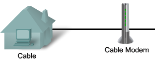
16 Broadband Technology Options Satellite broadband: A satellite modem transmits radio signals to a geosynchronous satellite and provides a local Ethernet connection. Broadband cable access: A special cable modem separates the Internet data signal from the other signals carried on the cable and provides a local Ethernet connection. Digital subscriber line (DSL): A special high-speed modem separates the DSL data signal from the telephone signal and provides a local Ethernet connection. 16
17 Wireless Broadband New developments in broadband wireless technology are increasing wireless availability. Popular deployments include: Municipal Wi-Fi WiMAX Satellite Internet Note: This list is not exhaustive and other types of wireless connectivity also exist. 17

18 Municipal WiFi Some municipal governments provide municipal wireless networks. These networks typically provide high-speed Internet access at no cost or for substantially less than other broadband services. Networks may be reserved only for official use by police, firefighters, and city workers. 18
19 Municipal WiFi Networks use a mesh topology rather than a hub-and-spoke model providing many benefits including: Installation is easier and can be less expensive because there are fewer wires. Deployment over a large urban area is faster. It is more reliable (If a node fails, others in the mesh compensate for it). 19

20 Municipal WiFi The Wireless mesh consists of a series of access points and each AP can communicate with two or more other APs. The mesh blankets its area with radio signals and the signals travel from AP to AP through this cloud. 20

21 WiMAX WiMAX (Worldwide Interoperability for Microwave Access) is telecommunications technology that provides wireless data over long distances in a variety of ways, from point-topoint links to full mobile cellular type access. 21
.")
22 WiMAX Components A tower that is similar in concept to a cellular telephone tower. A single WiMAX tower can provide coverage to an area as large 7,500 square kilometers (approximately 3,000 square miles). A WiMAX receiver that is similar in size and shape to a PCMCIA card, or built in to a laptop or other wireless device. 22
23 Satellite Internet Two-way satellite access is available worldwide and used in locations where land-based Internet access is not available, or for temporary installations. Internet access can be provided to vessels at sea, airplanes in flight, and vehicles moving on land. There are three ways to connect to the Internet using satellites: One-way multicast satellite Internet systems in which information is pushed to end-user sites and full interactivity is not possible. One-way terrestrial return satellite Internet systems use telephone modems to send outbound data and receive downloads from the satellite. Two-way satellite Internet sends data from remote sites via satellite to a hub, which then sends the data to the Internet. Two-way is the most common and practical implementation. 23

24 Two-way Satellite Internet Satellite services deliver data at downstream speeds up to 1,500 kbps, and upstream speeds as high as 125 kbps. Heavy activity on the network can affect satellite speeds. Asymmetrical nature of satellite communication does not lend itself well to voice applications. The distance between the subscriber and the orbiting satellite causes issues with delay-sensitive applications. 24
25 Broadband Cable Broadband cable is a popular option used by teleworkers to access enterprise networks. Although this solution still is not popular for connecting branch sites, it should nonetheless be considered as the technology matures. The cable system uses a coaxial cable that carries radio frequency (RF) signals across the network. Coaxial cable is the primary medium used to build cable TV systems. 25

26 History of Cable Technology Cable television was first employed in Mahanoy, Pennsylvania in 1948 by John Walson. He owned an appliance store and needed to solve poor over-the-air reception experienced by customers receiving TV signals from Philadelphia. Walson erected an antenna on a mountaintop utility pole that enabled his store to receive strong broadcasts from the Philadelphia stations. He then connected several of his customers who were located along the cable path. Walson s is recognized as the founder of the cable television industry. He was also the first: Cable operator to use microwave to import distant television stations To use coaxial cable to improve picture quality To distribute pay television programming. 26
27 Modern Cable System Modern cable systems provide two-way communication between subscribers and the cable operator. Enables the cable operator to provide high-speed Internet access, digital cable television, and residential telephone service. A modern cable network is capable of sending signals on the cable in either direction at the same time. Downstream: The direction of an RF signal transmission (TV channels and data) from the source (headend) to the destination (subscribers). Transmission from source to destination is called the forward path. Upstream: The direction of the RF signal transmission from subscribers to the headend, or the return or reverse path. 27

28 Cable Frequencies Upstream frequencies are in the range of 5 MHz to 42 MHz. Downstream frequencies are in the range of 50 MHz to 860 MHz. 28
29 Broadband Cable Components There are two types of equipment required on a cable system: Cable modem termination system (CMTS) at the cable operator end. Cable modem (CM) on the subscriber end. A CMTS communicates with CMs located in subscriber homes. The headend is actually a router with databases providing Internet services to cable subscribers. 29

30 Broadband Cable Plant The architecture consists of a hybrid fiber-coaxial (HFC) network in which optical fiber replaces the lower-bandwidth coaxial. A web of fiber trunk cables connects the headend to the nodes where optical-to-rf signal conversion takes place. Coaxial feeder cables from the node carry RF signals to the subscribers. 30
31 Broadband Cable In a modern HFC network, typically 500 to 2000 active data subscribers are connected to a cable network segment, all sharing the upstream and downstream bandwidth. When high usage causes congestion, the cable operator can add additional bandwidth for data services by allocating an additional TV channel for high-speed data. This addition may effectively double the downstream bandwidth that is available to subscribers. Another option is to reduce the number of subscribers served by each network segment and increase the number of fiber-optic connections. 31
32 Digital Subscriber Line (DSL) DSL is a family of broadband technologies that provides digital data transmission over the wires of a local telephone network. DSL service is delivered simultaneously with regular telephone on the same telephone line. It has become an efficient and effective option for corporate Internet access. Note: DSL will be used as the solution for the branch office scenario. 32
33 DSL Background Information In the early 1980 s, research by Bell Labs identified that a typical voice conversation over a plain old telephone service (POTS) local loop only required the use of frequencies in the range of 300 Hz to 3400 Hz. For years, the bandwidth greater than 4 KHz went unused. Plain Old Telephone System (POTS) Hz 3.4 khz 20 khz 140 khz 1 MHz Not to scale 33
34 DSL Background Information Advances in technology allow DSL to use the additional bandwidth from 4 KHz up to 1 MHz to deliver high-speed data services over ordinary copper lines. Plain Old Telephone System (POTS) Upstream ADSL Digital Subscriber Line Downstream (DSL) ADSL Hz 3.4 khz 20 khz 140 khz 1 MHz Not to scale 34
35 DSL Variants There are many variants of DSL that are distinguished by their nature, maximum data rate, data and voice support, line coding technology and maximum distance. DSL Variants * ADSL (Asymmetric DSL) HDSL (high bitrate DSL) SDSL (Symmetric DSL ) SHDSL (Single-pair high-speed DSL) VDSL (Very High bitrate DSL) Nature Asymmetric Symmetric Symmetric Symmetric Symmetric / Asymmetric Maximum Data Rates (Downstream / Upstream) 8 Mbps / 1 Mbps 2 Mbps / 2 Mbps 2 Mbps / 2 Mbps 2.3 Mbps / 2.3 Mbps 52 Mbps / 16 Mbps * Partial List 35
36 Asymmetric DSL (ADSL) Frequencies ADSL is the most commonly installed variety of DSL. Upstream frequencies are in the range of 20 KHz to 138 KHz. Downstream frequencies are in the range of 142 KHz to 1 MHz. Plain Old Telephone System (POTS) Upstream ADSL Downstream ADSL Hz 3.4 khz 20 khz 140 khz 1 MHz Not to scale 36
37 ADSL Infrastructure ADSL is not a complete end-to-end solution. All variants use a similar infrastructure. The customer requires an ADSL modem or router with an ADSL card. Voice traffic is filtered using an inline microfilter. 37
38 ADSL Infrastructure The ADSL connection is deployed in the last mile of a local telephone network. This is the area between the customers premise equipment (CPE) and the DSL Access Multiplexer (DSLAM). 38
39 ADSL Infrastructure A POTS splitter is a passive device (requires no power) installed at the central office (CO) to separate the POTS voice signal and ADSL signal. POTS traffic is forwarded to the Class 5 voice switch. ADSL traffic is forwarded to the DSLAM. 39
 or Point-to-Point Protocol over Ethernet (PPPoE) to connect to it.")
40 ADSL Infrastructure A DSL Access Multiplexer (DSLAM) is basically an ATM switch containing DSL interface cards (ATU-Cs) that concentrates connections from multiple DSL subscribers. Subscribers either use Point-to-Point Protocol over ATM (PPPoA) or Point-to-Point Protocol over Ethernet (PPPoE) to connect to it. 40
41 ADSL Example CPE Branch Local Loop Service Provider Network ATM Core Router DSLAM Internet DHCP Server The ADSL Layer 1 CPE connection terminates at the DSLAM. The data link layer protocol that is usually used over DSL is ATM. The DSLAM terminates the ADSL connections, and then switches the traffic over an ATM network to the service provider s core aggregation router. 41
42 ADSL Example CPE Branch Local Loop Service Provider Network ATM Core Router DSLAM Internet DHCP Server There are three ways to encapsulate IP packets over an ATM and DSL connection: RFC 1483/2684 Bridged Unpopular due to security and scalability issues. PPP over Ethernet (PPPoE) PPP over ATM (PPPoA) 42
43 ADSL PPPoA Example CPE Branch Local Loop Service Provider Network ATM Core Router DSLAM Internet DHCP Server The PPP connection is established between the CPE and the core router. The CPE device is configured with a username and password. The core router authenticates the users using either a local database or an external RADIUS AAA server. 43
44 ADSL PPPoA Example CPE Branch Local Loop Service Provider Network ATM Core Router DSLAM Internet DHCP Server Once authenticated, the PPP Internet Protocol Control Protocol (IPCP) negotiation takes place to assign an IP address to the CPE. The core router will provide an IP address from its DHCP server. The CPE can use NAT or PAT to support multiple inside hosts. 44
45 ADSL PPPoA Example CPE Branch Local Loop Service Provider Network ATM Core Router DSLAM Internet DHCP Server After the IP address has been assigned, a host route is established both on the CPE and the core router. 45
46 PPPoA Configuration Steps Example CPE Branch Local Loop Service Provider Network ATM Core Router DSLAM Internet DHCP Server 1. Configure an ATM interface. 2. Configure a dialer interface. 3. Configure NAT or PAT. 4. Configure the branch router as a local DHCP server. 5. Configure a static default route. 46
47 Configure ATM and Dialer Interfaces /24 CPE Service Provider Network Branch ATM 0/0 DSLAM ATM Core Router Internet DHCP Server Branch(config)# interface ATM0/0 Branch(config-if)# no ip address Branch(config-if)# dsl operating-mode auto Branch(config-if)# pvc 8/35 Branch(config-if-atm-vc)# en aal5mux ppp dialer Branch(config-if-atm-vc)# dialer pool-member 1 Branch(config-if-atm-vc)# no shutdown Branch(config-if-atm-vc)# exit Branch(config)# interface Dialer0 Branch(config-if)# ip address negotiated Branch(config-if)# encapsulation ppp Branch(config-if)# dialer pool 1 Branch(config-if)# ip nat outside Branch(config-if)# ppp authentication chap callin Branch(config-if)# ppp chap password MY-SECRET Branch(config-if)# ATM and PVC configuration are provided by the DSL service provider. Notice the combination of the ATM interface dialer pool-member 1 command and the dialer interface dialer-pool 1 commands. These two commands associate the ATM 0/0 interface to the Dialer 0 interface. The dialer interface initiates PPP connectivity, including PPP services such as user authentication. Notice that it is also identified as the outside NAT interface. 47
48 Configure NAT, DHCP, and Routing /24 CPE Service Provider Network Branch ATM 0/0 DSLAM ATM Core Router Internet DHCP Server Branch(config)# ip nat inside source list 101 interface Dialer0 overload Branch(config)# access-list 101 permit ip any Branch(config)# Branch(config)# ip dhcp pool MY-POOL Branch(dhcp-config)# network Branch(dhcp-config)# default-router Branch(dhcp-config)# exit Branch(config)# ip route Dialer0 Branch(config)# The PAT configuration permits the inside IP addresses to share the outside IP address. The Branch router provides DHCP services to users connected to the inside LAN interface using the pool. The static default route points to the dialer interface therefore routed traffic will trigger the dialer interface to activate. 48
49 Verifying PPPoA Confirm that the branch router has a route pointing to the dialer interface using the show ip route command. Verify IP connectivity using the ping and traceroute commands from an inside host to confirm proper PAT translation. Use the debug ppp authentication command to debug the PPP session authentication. Verify ATM connectivity using the debug atm events command. Finally, check Layer 1 connectivity and discover the DSL line status using the show dsl interface atm command. 49
50 Implementation Plan 1. Deploy broadband connectivity 2. Configure static routing 3. Document and verify other services 4. Implement and tune the IPsec VPN 5. Configure GRE tunnels Note: For simplicity reasons, the ADSL Internet link implemented in the previous step will be replaced by a Serial link. 50
51 Branch Static Routing Example Private WAN / / /24 S0/0/0 S0/0/ / Fa0/0 Branch HQ S0/0/1 Fa0/0.226 Internet /29 Branch Server ISP.225 NAT Pool /29 Server ( ) The HQ LAN is on network /24. The HQ router has an Internet connection to the ISP. The corporate server is located at IP address for internal users and at for remote users from the Internet. The Branch router LAN is on network /24. It also has a server accessible at IP address
52 Branch Static Routing Example Private WAN / / /24 S0/0/0 S0/0/ / Fa0/0 Branch HQ S0/0/1 Fa0/0.226 Internet /29 Branch Server ISP.225 NAT Pool /29 Server ( ) Network information is exchanged between the Branch and HQ routers using EIGRP across a private WAN link. The Branch LAN users access the Internet by using the default route propagated by the HQ router. All traffic that exits interface Serial 0/0/1 on the HQ router is subject to being translated by NAT. 52
53 Branch Static Routing Example Private WAN / / /24 S0/0/0 S0/0/ / Fa0/0 Branch HQ S0/0/1 S0/0/1 Fa0/ /29 Internet /29 Branch Server ISP.225 NAT Pool /29 Server ( ) The enterprise wishes to provide fault tolerance for branch users and has therefore provisioned an alternate link using the Internet. The new Internet connection is on subnet /29 connecting to interface Serial 0/0/1. This connection will serve as a backup route for the private WAN link. 53
54 Verifying EIGRP Branch# show ip protocols Routing Protocol is "eigrp 1" Outgoing update filter list for all interfaces is not set Incoming update filter list for all interfaces is not set Default networks flagged in outgoing updates Default networks accepted from incoming updates EIGRP metric weight K1=1, K2=0, K3=1, K4=0, K5=0 EIGRP maximum hopcount 100 EIGRP maximum metric variance 1 Redistributing: eigrp 1 EIGRP NSF-aware route hold timer is 240s Automatic network summarization is not in effect Maximum path: 4 Routing for Networks: / Routing Information Sources: Gateway Distance Last Update :08:19 Distance: internal 90 external 170 Branch# 54
55 Verifying EIGRP Branch# show ip route *Mar 26 03:45:38.207: %SYS-5-CONFIG_I: Configured from console by consolee Codes: C - connected, S - static, R - RIP, M - mobile, B - BGP D - EIGRP, EX - EIGRP external, O - OSPF, IA - OSPF inter area N1 - OSPF NSSA external type 1, N2 - OSPF NSSA external type 2 E1 - OSPF external type 1, E2 - OSPF external type 2 i - IS-IS, su - IS-IS summary, L1 - IS-IS level-1, L2 - IS-IS level-2 ia - IS-IS inter area, * - candidate default, U - per-user static route o - ODR, P - periodic downloaded static route Gateway of last resort is to network /30 is subnetted, 1 subnets C is directly connected, Serial0/0/ /29 is subnetted, 1 subnets C is directly connected, Serial0/0/ /24 is subnetted, 1 subnets D [90/ ] via , 00:00:17, Serial0/0/0 C /24 is directly connected, FastEthernet0/0 D*EX /0 [170/ ] via , 00:00:17, Serial0/0/0 55
56 Verify Connectivity to the Server Branch# ping source Type escape sequence to abort. Sending 5, 100-byte ICMP Echos to , timeout is 2 seconds: Packet sent with a source address of !!!!! Success rate is 100 percent (5/5), round-trip min/avg/max = 1/2/4 ms Branch# Branch# trace source Type escape sequence to abort. Tracing the route to msec 0 msec * Branch# 56
57 Verify Connectivity to the ISP Website Branch# ping source Type escape sequence to abort. Sending 5, 100-byte ICMP Echos to , timeout is 2 seconds: Packet sent with a source address of !!!!! Success rate is 100 percent (5/5), round-trip min/avg/max = 32/32/32 ms Branch# Branch# trace source Type escape sequence to abort. Tracing the route to msec 0 msec 0 msec msec 16 msec * Branch# 57
58 Configure a Default Floating Static Route Private WAN / / /24 S0/0/0 S0/0/ / Fa0/0 Branch HQ S0/0/1 S0/0/1 Fa0/ /29 Internet /29 Branch Server ISP.225 NAT Pool /29 Server ( ) Branch(config)# ip route Branch(config)# exit To enable the Internet link should the private WAN link fail, a default floating static route has been configured. Notice that the assigned administrative distance is greater than the current default route in the routing table with an administrative distance of
59 Test the Floating Static Route Branch# debug ip routing IP routing debugging is on Branch# conf t Enter configuration commands, one per line. End with CNTL/Z. Branch(config)# int s0/0/0 Branch(config-if)# shutdown Branch(config-if)# *Mar 26 06:22:23.759: RT: is_up: Serial0/0/0 0 state: 6 sub state: 1 line: 0 has_route: True *Mar 26 06:22:23.759: RT: interface Serial0/0/0 removed from routing table *Mar 26 06:22:23.759: RT: del /30 via , connected metric [0/0] *Mar 26 06:22:23.759: RT: delete subnet route to /30 *Mar 26 06:22:23.759: RT: NET-RED /30 *Mar 26 06:22:23.759: RT: delete network route to *Mar 26 06:22:23.759: RT: NET-RED /16 *Mar 26 06:22:23.759: RT: Pruning routes for Serial0/0/0 (3) *Mar 26 06:22:23.763: RT: delete route to via , Serial0/0/0 *Mar 26 06:22:23.763: RT: no routes to , flushing <Continued> 59
60 Test the Floating Static Route Mar 26 06:22:23.763: RT: NET-RED /24 *Mar 26 06:22:23.767: RT: delete network route to *Mar 26 06:22:23.767: RT: NET-RED /8 *Mar 26 06:22:23.767: RT: delete route to via , Serial0/0/0 *Mar 26 06:22:23.767: RT: no routes to , flushing *Mar 26 06:22:23.767: RT: NET-RED /0 *Mar 26 06:22:23.771: RT: add /0 via , static metric [171/0] *Mar 26 06:22:23.771: RT: NET-RED /0 *Mar 26 06:22:23.771: RT: default path is now via *Mar 26 06:22:23.771: RT: new default network *Mar 26 06:22:23.771: RT: NET-RED /0 *Mar 26 06:22:23.771: %DUAL-5-NBRCHANGE: IP-EIGRP(0) 1: Neighbor (Serial0/0/0) is down: interface down Branch(config-if)# end Branch# undebug all All possible debugging has been turned off Branch# 60
61 Verify the Routing Table Branch# show ip route Codes: C - connected, S - static, R - RIP, M - mobile, B - BGP D - EIGRP, EX - EIGRP external, O - OSPF, IA - OSPF inter area N1 - OSPF NSSA external type 1, N2 - OSPF NSSA external type 2 E1 - OSPF external type 1, E2 - OSPF external type 2 i - IS-IS, su - IS-IS summary, L1 - IS-IS level-1, L2 - IS-IS level-2 ia - IS-IS inter area, * - candidate default, U - per-user static route o - ODR, P - periodic downloaded static route Gateway of last resort is to network /29 is subnetted, 1 subnets C is directly connected, Serial0/0/ /24 is variably subnetted, 2 subnets, 2 masks C /24 is directly connected, FastEthernet0/0 S* /0 [171/0] via Branch# 61
62 Verify Connectivity the HQ Server Branch# ping source Type escape sequence to abort. Sending 5, 100-byte ICMP Echos to , timeout is 2 seconds: Packet sent with a source address of !!!!! Success rate is 100 percent (5/5), round-trip min/avg/max = 56/56/60 ms Branch# Branch# trace source Type escape sequence to abort. Tracing the route to msec 12 msec 16 msec msec 28 msec * Branch# It would appear that all is working as expected. However, the scenario as presented so far would really not be feasible, because the Branch s private addresses would be filtered by the ISP router. Therefore, the internal private IP addresses must be filtered using NAT. 62
63 Implementation Plan 1. Deploy broadband connectivity 2. Configure static routing 3. Document and verify other services 4. Implement and tune the IPsec VPN 5. Configure GRE tunnels 63
64 Document and Verify Other Services Private WAN / / /24 S0/0/0 S0/0/ / Fa0/0 Branch HQ S0/0/1 S0/0/1 Fa0/ /29 Internet /29 Branch Server ( ) NAT Pool / ISP.225 NAT Pool /29 Server ( ) The third step of the implementation plan was to verify branch services. Specifically, we will configure: A NAT pool of global IP addresses available on the branch router. A static NAT address ( ) to the Branch server. 64
65 Steps to Configuring NAT Private WAN / / /24 S0/0/0 S0/0/ / Fa0/0 Branch HQ S0/0/1 S0/0/1 Fa0/ /29 Internet /29 Branch Server ( ) NAT Pool / ISP.225 NAT Pool /29 Server ( ) 1. Identify which traffic will be translated using IP ACLs. 2. Identify what to translate to using the ip nat pool command. 3. Bind the ACL and pool together using the ip nat pool inside command. 4. Identify the inside and outside NAT interfaces using the ip nat inside and ip nat outside commands. 65
 NAT Pool 209.165.200.249 209.165.200.253/29.241 ISP.225 NAT Pool 209.165.200.233 209.165.200.237 /29 Email Server 10.10.10.238 (209.165.200.238) The first step in configuring NAT is to create an ACL that will declare which traffic will be translated.")
66 Configure the NAT ACL Private WAN / / /24 S0/0/0 S0/0/ / Fa0/0 Branch HQ S0/0/1 S0/0/1 Fa0/ /29 Internet /29 Branch Server ( ) NAT Pool / ISP.225 NAT Pool /29 Server ( ) The first step in configuring NAT is to create an ACL that will declare which traffic will be translated. It is important to understand that it is not used to filter the traffic but instead is used to designate which traffic will be translated by NAT. A permit statement in a NAT access list means "translate," and a deny statement in the same access list means "do not translate. 66
67 Configure the NAT ACL Example Private WAN / / /24 S0/0/0 S0/0/ / Fa0/0 Branch HQ S0/0/1 S0/0/1 Fa0/ /29 Internet /29 Branch Server ( ) NAT Pool / ISP.225 NAT Pool /29 Server ( ) Branch(config)# ip access-list extended BRANCH-NAT-ACL Branch(config-ext-nacl)# permit ip any Branch(config-ext-nacl)# exit The ACL states that traffic with source IP address /24 is targeted for translation by the permit statement. The unseen implicit deny statement will not translate any other addresses. 67
68 Configure a NAT Pool Specify criteria to be matched using ACLs or prefix lists. Router(config)# ip nat pool name start-ip end-ip {netmask netmask prefix-length prefix-length} Parameter name start-ip end-ip netmask netmask prefix-length prefix-length type rotary Description IP route prefix for the destination. Starting IP address of the address pool. Ending IP address of the address pool. Indicates which address bits that belong to the network and subnetwork fields and which bits belong to the host field. Indicates the netmask using the prefix length. Indicates that the range of addresses in the address pool identifies inside hosts on which TCP load distribution will occur. 68
69 Bind the ACL and NAT Pool Link the source IP addresses to the pool for dynamic address translation. Router(config)# ip nat inside source {list {access-list-number accesslist-name} route-map name} {interface type number pool name} [overload] Parameter name list access-list-number access-list-name route-map name interface type number pool name overload Description IP route prefix for the destination. Number or name of a standard IP access list. Specifies the named route map. Specifies the interface type and number. Name of pool from which addresses are allocated. (Optional) Enables the tracking of TCP or UDP port numbers. 69
70 Configure Static NAT Link a source IP addresses to a pool for static translation. Router(config)# ip nat inside source {static {local-ip global-ip} Parameter Description static local-ip global-ip Establishes the local IP address assigned to a host on the inside network. Establishes the global IP address assigned to a host on the inside network. 70
71 Identify NAT Interfaces Designate the NAT inside and outside interfaces. Router(config-if)# ip nat inside [inside outside] Parameter Description inside outside Indicates that the interface is connected to the inside network (the network subject to NAT translation). Indicates that the interface is connected to the outside network. 71
72 Configure the NAT Pool Example Private WAN / / /24 S0/0/0 S0/0/ / Fa0/0 Branch HQ S0/0/1 S0/0/1 Fa0/ /29 Internet /29 Branch Server ( ) NAT Pool / ISP.225 NAT Pool /29 Server ( ) Branch(config)# ip nat pool BRANCH-NAT-POOL netmask Branch(config)# Branch(config)#! Or use the prefix-length keyword Branch(config)# Branch(config)# ip nat pool BRANCH-NAT-POOL prefix-length 29 Branch(config)# 72
73 Bind the ACL and NAT Pool Example Private WAN / / /24 S0/0/0 S0/0/ / Fa0/0 Branch HQ S0/0/1 S0/0/1 Fa0/ /29 Internet /29 Branch Server ( ) NAT Pool / ISP.225 NAT Pool /29 Server ( ) Branch(config)# ip nat inside source list BRANCH-NAT-ACL pool BRANCH-NAT-POOL Branch(config)# 73
74 Configure Static NAT for the Server Private WAN / / /24 S0/0/0 S0/0/ / Fa0/0 Branch HQ S0/0/1 S0/0/1 Fa0/ /29 Internet /29 Branch Server ( ) NAT Pool / ISP.225 NAT Pool /29 Server ( ) Branch(config)# ip nat inside source static Branch(config)# 74
75 Identify Inside and Outside NAT Interfaces Private WAN / / /24 S0/0/0 S0/0/ / Fa0/0 Branch HQ S0/0/1 S0/0/1 Fa0/ /29 Internet /29 Branch Server ( ) NAT Pool / ISP.225 NAT Pool /29 Server ( ) Branch(config)# interface serial 0/0/1 Branch(config-if)# ip nat outside Branch(config-if)# Branch(config-if)# interface fastethernet 0/0 Branch(config-if)# ip nat inside Branch(config-if)# 75
76 Verifying and Troubleshooting NAT Command Description show ip nat translations Displays active NAT translations show ip nat statistics Displays NAT statistics. clear ip nat translation * clear ip nat statistics debug ip nat Clears all IP NAT translations. Clears all NAT statistics. Displays NAT translations as they occur. 76
77 Display NAT Translations and Statistics Branch# show ip nat translations Pro Inside global Inside local Outside local Outside global Branch# Branch# show ip nat statistics Total active translations: 1 (1 static, 0 dynamic; 0 extended) Peak translations: 1, occurred 00:31:21 ago Outside interfaces: Serial0/0/1 Inside interfaces: FastEthernet0/0 Hits: 0 Misses: 0 CEF Translated packets: 0, CEF Punted packets: 0 Expired translations: 0 Dynamic mappings: -- Inside Source [Id: 1] access-list BRANCH-NAT-ACL pool BRANCH-NAT-POOL refcount 0 pool BRANCH-NAT-POOL: netmask Appl doors: 0 Normal doors: 0 Queued Packets: 0 Branch# 77
78 Enable Debugging and Clear NAT Tables Private WAN / / /24 S0/0/0 S0/0/ / Fa0/0 Branch HQ S0/0/1 S0/0/1 Fa0/ /29 Internet /29 Branch Server ( ) NAT Pool / ISP.225 NAT Pool /29 Server ( ) Branch# debug ip nat IP NAT debugging is on Branch# clear ip nat statistics Branch# clear ip nat translation * Branch# 78
79 Telnet to Generate NAT Traffic Branch# telnet /source-interface fa0/0 Trying Open Password required, but none set *Mar 26 14:20:10.563: NAT: s= > , d= [10933] *Mar 26 14:20:10.591: NAT*: s= , d= > [60321] *Mar 26 14:20:10.595: NAT: s= > , d= [10934] *Mar 26 14:20:10.595: NAT: s= > , d= [10935] *Mar 26 14:20:10.595: NAT: s= > , d= [10936] *Mar 26 14:20:10.627: NAT*: s= , d= > [60322] *Mar 26 14:20:10.627: NAT: s= > , d= [10937] *Mar 26 14:20:10.627: NAT: s= > , d= [10938] *Mar 26 14:20:10.631: NAT: s= > , d= [10939] *Mar 26 14:20:10.639: NAT*: s= , d= > [60323] *Mar 26 14:20:10.827: NAT*: s= , d= > [60324] *Mar 26 14:20:10.839: NAT: s= > , d= [10940] [Connection to closed by foreign host] Branch# *Mar 26 14:20:12.723: NAT*: s= , d= > [60325] *Mar 26 14:20:12.723: NAT: s= > , d= [10941] *Mar 26 14:20:12.727: NAT: s= > , d= [10942] *Mar 26 14:20:12.759: NAT*: s= , d= > [60326] Branch# 79
80 Verify NAT Translations and Statistics Branch# show ip nat translations Pro Inside global Inside local Outside local Outside global tcp : : : : Branch# Branch# show ip nat statistics Total active translations: 3 (1 static, 2 dynamic; 1 extended) Peak translations: 3, occurred 00:13:14 ago Outside interfaces: Serial0/0/1 Inside interfaces: FastEthernet0/0 Hits: 32 Misses: 0 CEF Translated packets: 12, CEF Punted packets: 2 Expired translations: 1 Dynamic mappings: -- Inside Source [Id: 1] access-list BRANCH-NAT-ACL pool BRANCH-NAT-POOL refcount 2 pool BRANCH-NAT-POOL: netmask Appl doors: 0 Normal doors: 0 Queued Packets: 0 Branch# 80
81 Verify Static NAT on Branch Private WAN / / /24 S0/0/0 S0/0/ / Fa0/0 Branch HQ S0/0/1 S0/0/1 Fa0/ /29 Internet /29 Branch Server ( ) NAT Pool / ISP.225 NAT Pool /29 Server ( ) HQ# ping Type escape sequence to abort. Sending 5, 100-byte ICMP Echos to , timeout is 2 seconds:!!!!! Success rate is 100 percent (5/5), round-trip min/avg/max = 56/57/60 ms HQ# Ping the Branch Server public IP address to verify if static NAT is implemented properly. 81
82 Verify NAT Statistics Branch# *Mar 26 14:46:49.423: NAT*: s= , d= > [10] *Mar 26 14:46:49.427: NAT: s= > , d= [10] *Mar 26 14:46:49.483: NAT*: s= , d= > [11] *Mar 26 14:46:49.483: NAT: s= > , d= [11] *Mar 26 14:46:49.539: NAT*: s= , d= > [12] *Mar 26 14:46:49.539: NAT: s= > , d= [12] *Mar 26 14:46:49.599: NAT*: s= , d= > [13] *Mar 26 14:46:49.599: NAT: s= > , d= [13] Branch# *Mar 26 14:46:49.655: NAT*: s= , d= > [14] *Mar 26 14:46:49.655: NAT: s= > , d= [14] Branch# Branch# show ip nat translations Pro Inside global Inside local Outside local Outside global icmp : : : : Branch# 82
83 Verifying Other Services - DHCP Other services such as DHCP can also impact the Branch. Consider overlapping internal addresses assigned by DHCP /24 Private WAN / / / Fa0/0 Branch HQ Fa0/0 Internet ISP Consider overlapping IP subnets across the VPN 83
84 Verifying Other Services - ACLs Edge routers must also be capable of forwarding protocols required to support IPsec VPNs, such as the following: Encapsulation Security Payload (ESP) (IP protocol 50). Authentication Header (AH), (IP protocol 51). Internet Security Association and Key Management Protocol (ISAKMP) (UDP port 500). 84
85 Verifying Other Services - HSRP Hot Standby Router Protocol (HSRP) could be configured at a branch site to provide redundancy at the edge routers. HSRP would decide to switch to another active router upon failure and would define the traffic flow. Branch-A Private WAN HQ Branch-B Internet When the link to Branch-A fails, Branch-B automatically takes over as the active router and now defines the default traffic flows. 85
86 Implementation Plan 1. Deploy broadband connectivity 2. Configure static routing 3. Document and verify other services 4. Implement and tune the IPsec VPN 5. Configure GRE tunnels 86
87 Implement and tune the IPsec VPN The fourth step of the implementation plan was to implement an IPsec VPN. Using public networks to provide connectivity has many advantages including availability and relatively low cost. However, there are many issues with providing connectivity through the Internet including: Lack of security Loss of transparency and increased complexity IPsec seeks to resolve both issues. 87
88 VPN Solutions There are basically two VPN solutions: Site-to-site VPNs VPN endpoints are devices such as routers. The VPN is completely hidden from the users. Remote-access VPNs A mobile user initiates a VPN connection request using either VPN client software or an Internet browser and SSL connection. 88

89 Site-to-Site VPNs 89

90 Remote Access VPNs 90
91 IPsec Technologies IPsec VPNs provide two significant benefits: Encryption Encapsulation IPsec encryption provides three major services: Confidentiality Integrity Authentication 91
92 IPsec Encapsulation IPsec is capable of tunneling packets using an additional encapsulation. New IP Header ESP Header Original IP Header TCP Data ESP Trailer ESP Authentication Encrypted Authenticated 92
93 IPsec Encapsulation Example / / IPsec VPN.1 Fa0/0 Branch S0/0/1 S0/0/1 HQ Fa0/ /29 Internet / Original IP Header Source IP: Destination: TCP Data ISP Original IP Header Source IP: Destination: TCP Data New IP Header Source: Destination: ESP Header Original IP Header Source IP: Destination: TCP Data ESP Trailer ESP Authentication The example displays how a packet is encapsulated. 93
 NAT Pool 209.165.200.249 209.165.200.253/29.241 ISP.225 NAT Pool 209.165.200.233 209.165.200.237 /29 Email Server 10.10.10.238 (209.165.200.238) The Branch router has been configured to support an IPsec VPN when connecting to the HQ site.")
94 IPsec Site-to-Site VPN Example / / Fa0/0 Branch S0/0/1.242 IPsec VPN HQ S0/0/1 Fa0/ /29 Internet /29 Branch Server ( ) NAT Pool / ISP.225 NAT Pool /29 Server ( ) The Branch router has been configured to support an IPsec VPN when connecting to the HQ site. The purpose of the IPsec VPN link is to serve as a backup link in case the private WAN link fails. The long-term goal is to decommission the WAN link completely and use only the VPN connection to communicate between the branch office and the headquarters. 94
95 Steps to Configuring an IPsec VPN / / Fa0/0 Branch S0/0/1.242 IPsec VPN HQ S0/0/1 Fa0/ /29 Internet /29 Branch Server ( ) NAT Pool / ISP.225 NAT Pool /29 Server ( ) 1. Configure the initial key (ISAKMP policy) details. 2. Configure the IPsec details. 3. Configure the crypto ACL. 4. Configure the VPN tunnel information. 5. Apply the crypto map. 95
96 IPsec VPN Components ISAKMP Policy Contains authentication, encryption and the hashing method commands that are first used to negotiate and exchange credentials with a VPN peer. IPsec Details Identifies an acceptable combination of security protocols, algorithms, and other settings. Crypto ACL Is an extended IP ACL that identifies the traffic to be protected. A permit statement results in the traffic being encrypted, while a deny statement sends traffic out in clear text. Both VPN peers must have reciprocating ACLs. 96
97 IPsec VPN Components VPN Tunnel Information Binds all tunnel information together. Identifies the IPsec transform set to use, the peer router, the ACL, and other tunnel information. Apply the Crypto Map The named crypto map must be applied to the Internet-facing interface to which the peering router will connect to. 97
98 Branch Router IPsec VPN Configuration Branch# conf t Branch(config)# crypto isakmp policy 1 Branch(config-isakmp)# encryption aes Branch(config-isakmp)# authentication pre-share Branch(config-isakmp)# group 2 Branch(config-isakmp)# exit Branch(config)# crypto isakmp key cisco123 address IPsec Details Branch(config)# Specifies how the IPsec packet will Branch(config)# crypto ipsec transform-set HQ-VPN esp-sha-hmac esp-3des be encapsulated Branch(cfg-crypto-trans)# exit Branch(config)# Branch(config)# access-list 110 permit ip Branch(config)# Branch(config)# Branch(config)# crypto map HQ-MAP 10 ipsec-isakmp % NOTE: This new crypto map will remain disabled until a peer Branch(config-crypto-map)# set transform-set HQ-VPN Branch(config-crypto-map)# set peer Branch(config-crypto-map)# match address 110 Branch(config-crypto-map)# exit Branch(config)# int s0/0/1 Branch(config-if)# crypto map HQ-MAP Branch(config-if)# ^Z Branch# ISAKMP Policy Specifies the initial VPN security details Crypto ACL Specifies the traffic that will trigger the VPN to activate VPN Tunnel Information Creates the crypto map that combines the ISAKMP policy, IPsec transform set, VPN peer address, and crypto ACL Apply the Crypto Map Identifies which interface is actively looking to create a VPN 98
99 Verifying and Troubleshooting IPsec Command show crypto map show crypto session show crypto ipsec sa debug crypto ipsec Description Displays display the specifics contained in a crypto map configuration. Displays the status information of the active crypto sessions. Displays the settings used by current SAs. View real time IPsec events. 99
100 IPsec VPN Verification Example / / Fa0/0 Branch S0/0/1.242 IPsec VPN HQ S0/0/1 Fa0/ /29 Internet /29 Branch Server ( ) NAT Pool / ISP.225 NAT Pool /29 Server ( ) Branch# debug crypto ipsec Crypto IPSEC debugging is on Branch# ping source Type escape sequence to abort. Sending 5, 100-byte ICMP Echos to , timeout is 2 seconds: Packet sent with a source address of !!!!! Success rate is 100 percent (5/5), round-trip min/avg/max = 56/56/60 ms Branch# Enable IPsec debugging and generate interesting VPN traffic. Notice that the ping traffic matches the crypto ACL 110 however, no debug output is generated. access-list 110 permit ip
101 IPsec VPN Verification Example / / Fa0/0 Branch S0/0/1.242 IPsec VPN HQ S0/0/1 Fa0/ /29 Internet /29 Branch Server ( ) NAT Pool / ISP.225 NAT Pool /29 Server ( ) Branch# show crypto session Crypto session current status Interface: Serial0/0/1 Session status: DOWN Peer: port 500 IPSEC FLOW: permit ip / / Active SAs: 0, origin: crypto map <output omitted> Although the ping was successful, it appears that the tunnel is down. Recall that in the last implementation step, we implemented NAT. Perhaps this is causing some problems with the IPsec tunnel being created. 101
102 IPsec VPN Verification Example / / Fa0/0 Branch S0/0/1.242 IPsec VPN HQ S0/0/1 Fa0/ /29 Internet /29 Branch Server ( ) NAT Pool / ISP.225 NAT Pool /29 Server ( ) Branch# debug ip nat IP NAT debugging is on Branch# ping source Type escape sequence to abort. Sending 5, 100-byte ICMP Echos to , timeout is 2 seconds: Packet sent with a source address of !!!!! Success rate is 100 percent (5/5), round-trip min/avg/max = 56/57/60 ms Branch# Enable NAT debugging and ping again. The pings are again successful. 102
103 IPsec VPN Verification Example / / Fa0/0 Branch S0/0/1.242 IPsec VPN HQ S0/0/1 Fa0/ /29 Internet /29 Branch Server ( ) NAT Pool / ISP.225 NAT Pool /29 Server ( ) Branch# *Mar 26 16:35:21.251: NAT: s= > , d= [35] *Mar 26 16:35:21.307: NAT*: s= , d= > [35] *Mar 26 16:35:21.307: NAT: s= > , d= [36] *Mar 26 16:35:21.367: NAT*: s= , d= > [36] *Mar 26 16:35:21.367: NAT: s= > , d= [37] *Mar 26 16:35:21.423: NAT*: s= , d= > [37] *Mar 26 16:35:21.423: NAT: s= > , d= [38] *Mar 26 16:35:21.479: NAT*: s= , d= > [38] *Mar 26 16:35:21.483: NAT: s= > , d= [39] *Mar 26 16:35:21.539: NAT*: s= , d= > [39] Branch# The NAT debug output indicates that the internal IP address is being translated to
104 IPsec VPN Verification Example / / Fa0/0 Branch S0/0/1.242 IPsec VPN HQ S0/0/1 Fa0/ /29 Internet /29 Branch Server ( ) NAT Pool / ISP.225 NAT Pool /29 Server ( ) Branch# show access-lists Extended IP access list permit ip Extended IP access list BRANCH-NAT-ACL 10 permit ip any (1 match) Branch# BRANCH-NAT-ACL identifies traffic to translate and has one match. ACL 110 is for the IPsec VPN. What is the solution to this problem? 104
105 IPsec VPN Verification Example / / Fa0/0 Branch S0/0/1.242 IPsec VPN HQ S0/0/1 Fa0/ /29 Internet /29 Branch Server ( ) NAT Pool / ISP.225 NAT Pool /29 Server ( ) Branch(config)# no ip access-list extended BRANCH-NAT-ACL Branch(config)# ip access-list extended BRANCH-NAT-ACL Branch(config-ext-nacl)# deny ip Branch(config-ext-nacl)# permit ip any Branch(config-ext-nacl)# ^Z Branch Alter the NAT ACL to exempt VPN traffic. The ACL should ignore the Branch LAN traffic going to the HQ LAN! 105
106 IPsec VPN Verification Example / / Fa0/0 Branch S0/0/1.242 IPsec VPN HQ S0/0/1 Fa0/ /29 Internet /29 Branch Server ( ) NAT Pool / ISP.225 NAT Pool /29 Server ( ) Branch# clear ip nat translation * Branch# clear crypto isakmp Branch# clear crypto sa Branch# ping source Type escape sequence to abort. Sending 5, 100-byte ICMP Echos to , timeout is 2 seconds: Packet sent with a source address of !!!!! Success rate is 100 percent (5/5), round-trip min/avg/max = 56/57/60 ms Branch# Clear the NAT translations and IPsec SAs and generate interesting VPN traffic. 106
107 IPsec VPN Verification Example / / Fa0/0 Branch S0/0/1.242 IPsec VPN HQ S0/0/1 Fa0/ /29 Internet /29 Branch Server ( ) NAT Pool / ISP.225 NAT Pool /29 Server ( ) *Mar 26 18:28:45.166: IPSEC(sa_request):, (key eng. msg.) OUTBOUND local= , remote= , local_proxy= / /0/0 (type=4), remote_proxy= / /0/0 (type=4), protocol= ESP, transform= esp-3des esp-sha-hmac (Tunnel), lifedur= 3600s and kb, spi= 0x0(0), conn_id= 0, keysize= 0, flags= 0x0 *Mar 26 18:28:45.730: IPSEC(validate_proposal_request): proposal part #1 <output omitted> *Mar 26 18:28:45.738: IPSEC(update_current_outbound_sa): updated peer current outbound sa to SPI 1C838B72!!!! Success rate is 80 percent (4/5), round-trip min/avg/max = 88/89/92 ms Branch# 107
108 IPsec VPN Verification Example / / Fa0/0 Branch S0/0/1.242 IPsec VPN HQ S0/0/1 Fa0/ /29 Internet /29 Branch Server ( ) NAT Pool / ISP.225 NAT Pool /29 Server ( ) Branch# show crypto session Crypto session current status Interface: Serial0/0/1 Session status: UP-ACTIVE Peer: port 500 IKE SA: local /500 remote /500 Active IPSEC FLOW: permit ip / / Active SAs: 2, origin: crypto map Branch# 108
109 IPsec VPN Verification Example / / Fa0/0 Branch S0/0/1.242 IPsec VPN HQ S0/0/1 Fa0/ /29 Internet /29 Branch Server ( ) NAT Pool / ISP.225 NAT Pool /29 Server ( ) Branch# show crypto ipsec sa interface: Serial0/0/1 Crypto map tag: HQ-MAP, local addr protected vrf: (none) local ident (addr/mask/prot/port): ( / /0/0) remote ident (addr/mask/prot/port): ( / /0/0) current_peer port 500 PERMIT, flags={origin_is_acl,} #pkts encaps: 4, #pkts encrypt: 4, #pkts digest: 4 #pkts decaps: 4, #pkts decrypt: 4, #pkts verify: 4 #pkts compressed: 0, #pkts decompressed: 0 #pkts not compressed: 0, #pkts compr. failed: 0 <output omitted> 109
110 IPsec VPN Verification Example / / Fa0/0 Branch S0/0/1.242 IPsec VPN HQ S0/0/1 Fa0/ /29 Internet /29 Branch Server ( ) NAT Pool / ISP.225 NAT Pool /29 Server ( ) The example confirmed that the Branch router and HQ router have an established VPN. Notice how a service such as NAT could impact the creation of the VPN tunnel. 110
111 IPsec VPN Verification Example / / Fa0/0 Branch S0/0/1.242 IPsec VPN HQ S0/0/1 Fa0/ /29 Internet /29 Branch Server ( ) NAT Pool / ISP.225 NAT Pool /29 Server ( ) Currently the VPN link is only enabled due to static routing. What would happen if EIGRP was configured to operate over the link? Would it work? 111
112 IPsec VPN Verification Example / / Fa0/0 Branch S0/0/1.242 IPsec VPN HQ S0/0/1 Fa0/ /29 Internet /29 Branch Server ( ) NAT Pool / ISP.225 NAT Pool /29 Server ( ) A significant drawback of an IPsec VPN is that it cannot route multicast and broadcast packets and therefore cannot support IGPs. However, IPsec can be combined with generic routing encapsulation (GRE) to create a tunnel to circumvent the issue. 112
113 Implementation Plan 1. Deploy broadband connectivity 2. Configure static routing 3. Document and verify other services 4. Implement and tune the IPsec VPN 5. Configure GRE tunnels 113
114 Routing IGPs Using IPsec Point-to-point generic routing encapsulation (P2P GRE) IGPs are associated with tunnel interfaces which use the physical interface of the router to send GRE traffic. GRE traffic will have to be added to the crypto ACL. Virtual tunnel interface (VTI) IPsec endpoints are associated with routable virtual interfaces at the tunnel endpoints. VTI is a good alternative to IPsec over GRE tunnels. Dynamic multipoint VPN (DMVPN) or Group encrypted transport VPN (GET VPN) Both designed for large scale full mesh IPsec VPN implementations. 114
115 GRE Overview Tunneling protocol developed by Cisco. Can encapsulate a wide variety of network layer protocol packets inside IP tunnels. GRE is commonly implemented with IPsec to support IGPs. GRE is just an encapsulation protocol. By default, the traffic leaves in clear text. Therefore, GRE tunnels do not provide encryption services. IPsec must also be configured to encrypt the routing traffic. Note: IPsec was designed to tunnel IP only (no multiprotocol support) Older IOS versions do not support IP multicast over IPsec 115
116 Sending IGP Traffic Over IPsec Routing protocols are encapsulated with a GRE header. The packet encapsulated by GRE is then encapsulated with IPsec. Therefore, IPsec encrypts the GRE packet which contains the routing update. Routing Protocol Updates GRE Tunnel IPsec Crypto Map IPsec Encrypted Traffic 116
117 Transport, Carrier, Passenger Protocols In our scenario, the payload of GRE packets will be EIGRP routing updates and LAN-to-LAN corporate traffic. The GRE packet will then be encapsulated inside an IPsec packet. Therefore, IPsec is the transport protocol, and GRE is the carrier protocol used to carry other passenger protocols, such as IP broadcast or IP multicast, and non-ip protocols Transport Protocol IPsec (New IP Header) Carrier Protocol GRE Passenger Protocol Network Packet (Original IP header and Data) 117
118 GRE Encapsulation Passenger Protocol Original IP Header TCP Data Carrier Protocol GRE Encapsulation GRE IP Header GRE GRE Original IP Header TCP Data Transport Protocol IPsec Encapsulation (Tunnel Mode) New IP / UDP Header ESP Header GRE IP Header GRE GRE Original IP Header TCP Data ESP Trailer ESP Authentication 118
119 Steps to Configuring GRE / /24 GRE Tunnel / Fa0/0 Branch HQ S0/0/1 S0/0/1 Fa0/ /29 Internet /29 Branch Server ( ) NAT Pool / ISP.225 NAT Pool /29 Server ( ) 1. Create a tunnel interface for GRE. 2. Configure GRE tunnel parameters including IP address, source and destination tunnel addresses, and tunnel mode. 3. Change the crypto ACL to encrypt GRE traffic. 4. Configure routing protocols to route through the GRE tunnel. 119
120 Create a Tunnel Interface Create a tunnel interface. Router(config)# interface tunnel number Command creates a tunnel interface which is a virtual. Once in interface configuration mode, configure the tunnel parameters including: IP address Tunnel source Tunnel destination Tunnel mode (type of tunnel) 120
121 Identify the GRE Tunnel Source Identify the source of the GRE tunnel. Router(config-if)# tunnel source {ip-address ipv6-address interface-type interface-number} Parameter ip-address ipv6-address interface-type number Description IP address to use as the source address for packets in the tunnel. IPv6 address to use as the source address for packets in the tunnel. Interface type, such as loopback interface. Port, connector, or interface card number. 121
122 Identify the GRE Tunnel Destination Identify the destination of the GRE tunnel. Router(config-if)# tunnel destination {ip-address ipv6-address interface-type interface number} Parameter ip-address ipv6-address interface-type number Description IP address to use as the destination address for packets in the tunnel. IPv6 address to use as the destination address for packets in the tunnel. Interface type, such as loopback interface. Port, connector, or interface card number. 122
123 Identify the Tunnel Mode Set the encapsulation mode for the tunnel interface. Router(config-if)# tunnel mode {aurp cayman dvmrp eon gre ip gre multipoint gre ipv6 ipip [decapsulate-any] ipsec ipv4 iptalk ipv6 ipsec ipv6 mpls nos rbscp} Optional command since the default tunnel mode is tunnel mode gre ip Of interest to us is specifically the tunnel mode gre option. The additional options listed are for reference only. 123
124 Configuring GRE Example / /24 GRE Tunnel / Fa0/0 Branch HQ S0/0/1 S0/0/1 Fa0/ /29 Internet /29 Branch Server ( ) NAT Pool / ISP.225 NAT Pool /29 Server ( ) Branch(config)# interface tunnel 0 Branch(config-if)# ip address Branch(config-if)# tunnel source Branch(config-if)# tunnel destination Branch(config-if)# *Mar 27 15:45:05.647: %LINEPROTO-5-UPDOWN: Line protocol on Interface Tunnel0, changed state to up Branch(config-if)# Configure the tunnel interface on the Branch router. 124
125 Configuring GRE Example / /24 GRE Tunnel / Fa0/0 Branch HQ S0/0/1 S0/0/1 Fa0/ /29 Internet /29 Branch Server ( ) NAT Pool / ISP.225 NAT Pool /29 Server ( ) HQ(config)# interface Tunnel0 HQ(config-if)# ip address HQ(config-if)# tunnel source HQ(config-if)# tunnel destination HQ(config-if)# *Mar 27 10:50:59.151: %LINEPROTO-5-UPDOWN: Line protocol on Interface Tunnel0, changed state to up HQ(config)# Configure the tunnel interface on the HQ router. 125
126 Verify the Tunnel Configuration Branch# show interfaces tunnel 0 Tunnel0 is up, line protocol is up Hardware is Tunnel Internet address is /30 MTU bytes, BW 100 Kbit/sec, DLY usec, reliability 255/255, txload 1/255, rxload 1/255 Encapsulation TUNNEL, loopback not set Keepalive not set Tunnel source , destination Tunnel protocol/transport GRE/IP Key disabled, sequencing disabled Checksumming of packets disabled Tunnel TTL 255 Fast tunneling enabled Tunnel transport MTU 1476 bytes Tunnel transmit bandwidth 8000 (kbps) Tunnel receive bandwidth 8000 (kbps) Last input never, output never, output hang never Last clearing of "show interface" counters never Input queue: 0/75/0/0 (size/max/drops/flushes); Total output drops: 0 Queueing strategy: fifo Output queue: 0/0 (size/max) 5 minute input rate 0 bits/sec, 0 packets/sec 5 minute output rate 0 bits/sec, 0 packets/sec <output omitted> 126
127 Configuring GRE Example / /24 GRE Tunnel / Fa0/0 Branch HQ S0/0/1 S0/0/1 Fa0/ /29 Internet /29 Branch Server ( ) NAT Pool / ISP.225 NAT Pool /29 Server ( ) Branch(config)# no access-list 110 Branch(config)# access-list 110 permit gre host host Branch(config)# router eigrp 1 Branch(config-router)# network Branch(config-router)# network Branch(config-router)# no auto-summary Branch(config-router)# Change the ACL and add the Internet link and GRE tunnel network to EIGRP on the Branch router. 127
128 Configuring GRE Example / /24 GRE Tunnel / Fa0/0 Branch HQ S0/0/1 S0/0/1 Fa0/ /29 Internet /29 Branch Server ( ) NAT Pool / ISP.225 NAT Pool /29 Server ( ) HQ(config)# no access-list 110 HQ(config)# access-list 110 permit gre host host HQ(config)# router eigrp 1 HQ(config-router)# network HQ(config-router)# network HQ(config-router)# no auto-summary HQ(config-router)# *Mar 27 12:02:52.483: %DUAL-5-NBRCHANGE: IP-EIGRP(0) 1: Neighbor (Tunnel0) is up: new adjacency HQ(config-router)# Do the same on the HQ router. 128
129 Verifying GRE Example / /24 GRE Tunnel / Fa0/0 Branch HQ S0/0/1 S0/0/1 Fa0/ /29 Internet /29 Branch Server ( ) NAT Pool / ISP.225 NAT Pool /29 Server ( ) Branch# show ip eigrp neighbors IP-EIGRP neighbors for process 1 H Address Interface Hold Uptime SRTT RTO Q Seq (sec) (ms) Cnt Num Tu :00: Branch# Notice that the EIGRP neighbor is at the GRE tunnel IP address
130 Verifying GRE Example / /24 GRE Tunnel / Fa0/0 Branch HQ S0/0/1 S0/0/1 Fa0/ /29 Internet /29 Branch Server ( ) NAT Pool / ISP.225 NAT Pool /29 Server ( ) Branch# ping source Type escape sequence to abort. Sending 5, 100-byte ICMP Echos to , timeout is 2 seconds: Packet sent with a source address of !!!!! Success rate is 100 percent (5/5), round-trip min/avg/max = 100/100/100 ms Branch# Pings successfully cross the Internet link over the IPsec VPN. 130
131 Verify the GRE Over IPsec Configuration Branch# show crypto session detail Crypto session current status Code: C - IKE Configuration mode, D - Dead Peer Detection K - Keepalives, N - NAT-traversal, T - ctcp encapsulation X - IKE Extended Authentication, F - IKE Fragmentation Interface: Serial0/0/1 Uptime: 00:35:47 Session status: UP-ACTIVE Peer: port 500 fvrf: (none) ivrf: (none) Phase1_id: Desc: (none) IKE SA: local /500 remote /500 Active Capabilities:(none) connid:1002 lifetime:23:24:11 IPSEC FLOW: permit 47 host host Active SAs: 2, origin: crypto map Inbound: #pkts dec'ed 142 drop 0 life (BPSKBPSec) /1452 Outbound: #pkts enc'ed 211 drop 1 life (BPSKBPSec) /1452 Branch# 131

132 Planning for Mobile Worker Implementations 132
133 Connecting a Mobile Worker There are many challenges to connecting an increasingly mobile workforce. Mobile workers have become power users who may not even need a full-time office but require a professional environment and support services on-demand. From collaboration to presence services, remote-access solutions are an extension of the converged network and present similar requirements in terms of security, quality of service (QoS), and management transparency. 133
134 Enterprise Mobile Worker Considerations In addition to the regular and Internet support, mobile workers are increasingly requesting support for highbandwidth applications including: Mission-critical applications Real-time collaboration Voice Video Videoconferencing Therefore, a major consideration when connecting a mobile worker is the choice of a suitable network access technology. 134


135 Connecting Mobile Workers 135
136 Enterprise Mobile Worker Considerations Other mobile worker considerations include: Security Authentication IPsec and Secure Sockets Layer (SSL) VPNs Quality of Service (QoS): Management 136
137 Enterprise Mobile Worker Considerations Security: Security options safeguard the corporate network and close unguarded back doors. Deploying firewall, intrusion prevention, and URL filtering services meets most security needs. Authentication: Authentication defines who gains access to resources. Identity-based network services using authentication, authorization, and accounting (AAA) servers, 802.1X port-based access control, Cisco security, and trust agents are used. 137
138 Enterprise Mobile Worker Considerations IPsec and Secure Sockets Layer (SSL) VPNs: Encrypts traffic traversing unsecure links. The type of VPN must be carefully considered and implemented Site-to-site VPNs provide an always-on transparent VPN connection. Remote access VPNs provide on-demand secured connections. Quality of Service (QoS): QoS mechanisms prioritize the traffic and ensure adequate performance for applications that are sensitive to delay and jitter (for example, voice and video). 138
139 Enterprise Mobile Worker Considerations Management: Information Technology (IT) staff centrally manage and support teleworker connections and equipment, and transparently configure and push security and other policies to the remote devices. Tools are available that implement performance and fault management and monitor service level agreements (SLAs). 139
140 Business-Ready Mobile User Solution The Cisco enterprise teleworker broadband solution to deliver an always-on, secure voice and data service to SOHOs creating a flexible work environment. The always-on VPN grants employees easy access to authorized services and applications. Adding IP phones enhances productivity by allowing access to centralized IP communications with voice and unified messaging. Centralized management minimizes support overhead and costs. Integrated security allows easy extension of HQ security policies to teleworkers. 140
141 Connecting Mobile Workers Remote-Access VPN users will use a portable device (i.e., laptop) to initiate a VPN connection using either a VPN client software or an SSL Internet browser connection. SOHO with a DSL Router is an example of a business-ready mobile worker. The routers maintain an always-on site-to-site IPsec VPN connection and the VPN is completely hidden to the user. The choice of implementation will affect the routing solution. 141

142 Components for Mobile Workers A mobile worker solution usually has three major components: Components located at the mobile worker s remote site Corporate components located at the central site Optional IP telephony and other services. May be embedded into the user laptop via soft phones and other applications. 142
143 Business-Ready VPN Components Cisco Easy VPN Server : A Cisco IOS router or Cisco PIX / ASA Firewall configured as the VPN headend device in site-to-site or remote-access VPNs. And either: Cisco Easy VPN Remote: A Cisco IOS router or Cisco PIX / ASA Firewall acting as a remote VPN client. Cisco Easy VPN Client An application supported on a PC used to access a Cisco VPN server. 143
144 Cisco Easy VPN Exchange 144

145 Routing Traffic to the Mobile Worker 145
146 Easy VPN Server The Cisco Easy VPN server feature is usually configured on the headend VPN router (typically the edge router). It concentrates the bulk of the remote-end configuration, which pushes the policies to the client at the moment of connection. At the remote end, the device used by the mobile worker is known as the Easy VPN remote or Easy VPN client. The Easy VPN remote device starts an IPsec VPN tunnel to connect to the Easy VPN server across the public network. 146
147 VPN Headend Router Implementation Plan 1. Allow IPsec traffic 2. Define an address pool for connecting clients. 3. Provide routing services for VPN subnets. 4. Tune NAT for VPN traffic flows. 5. Verify IPsec VPN configuration Note: For simplicity reasons, the scenario used in the following steps are loosely connected examples Therefore, the network and IP addressing may vary between steps. 147
148 Allow IPsec Traffic Lo R /24.1 R Internet Address Pool Server /24 An enterprise edge router, such as R1, typically provides firewall security, antispoofing mechanisms and other security controls using either: Context-based access control (CBAC): A classic traditional firewall method based on ACLs. Zone-based policy firewall (ZPF): A more recent method based on security zones and access. It is important to identify the type of firewall configured to determine what needs to be changed. 148
149 Allow IPsec Traffic - CBACs Lo R /24.1 R Internet Server /24 Address Pool R1# show ip interface fa0/1 Broadcast address is Address determined by setup command MTU is 1500 bytes Helper address is not set Directed broadcast forwarding is disabled Multicast reserved groups joined: Outgoing access list is not set Inbound access list is FIREWALL-INBOUND Proxy ARP is enabled Local Proxy ARP is disabled <output omitted> 149
150 Allow IPsec Traffic - CBACs Lo R /24.1 R Internet Server /24 Address Pool R1# show access-lists Extended IP access list FIREWALL-INBOUND 10 permit eigrp any any (1452 matches) 20 permit tcp any any eq telnet 30 permit icmp any any (20 matches) 40 permit tcp any host eq.www 50 permit tcp any host eq ftp 60 permit udp any any eq domain Extended IP access list NAT-ACL 10 permit ip any (2 matches) R1# 150
151 Allow IPsec Traffic - CBACs R1# show ip inspect interfaces Interface Configuration Interface FastEthernet0/0 Inbound inspection rule is INSPECTION tcp alert is on audit-trail is off timeout 3600 udp alert is on audit-trail is off timeout 30 icmp alert is on audit-trail is off timeout 10 Outgoing inspection rule is not set Inbound access list is ALL Outgoing access list is not set Interface FastEthernet0/1 Inbound inspection rule is INSPECTION tcp alert is on audit-trail is off timeout 3600 udp alert is on audit-trail is off timeout 30 icmp alert is on audit-trail is off timeout 10 Outgoing inspection rule is not set Inbound access list is FIREWALL-INBOUND Outgoing access list is not set R1# R1# show zone-pair security R1# Confirms that CBACs were configured. Lack of output indicates ZBF is not configured. 151
152 Allow IPsec Traffic - CBACs Lo R /24.1 R Internet Address Pool Server /24 R1(config)# ip access-list extended FIREWALL-INBOUND R1(config-ext-nacl)# 4 permit 50 any any R1(config-ext-nacl)# 5 permit 51 any any R1(config-ext-nacl)# 6 permit udp any any eq 500 R1(config-ext-nacl)# 7 permit udp any any eq 4500 The named ACL FIREWALL-INBOUND is edited to support IPsec: Protocol 50 (ESP) Protocol 51 (AH) UDP port 500 (ISAKMP) UDP port 4500 (NAT-T). The configuration adds these lines before the current line number
153 VPN Headend Router Implementation Plan 1. Allow IPsec traffic 2. Define an address pool for connecting clients. 3. Provide routing services for VPN subnets. 4. Tune NAT for VPN traffic flows. 5. Verify IPsec VPN configuration 153
154 Defining an Address Pool Lo R /24.1 R Internet Address Pool Server /24 R1# config t R1(config)# ip local pool EZVPN R1(config)# The address is the reachable outside address. However, the remote host requires an internal private address. The pool named EZVPN provides addresses from the /24 subnet to be allocated to the remote hosts. Note: Although in this example the x address is used, the actual pool would normally be a routed (public) address. 154
155 VPN Headend Router Implementation Plan 1. Allow IPsec traffic. 2. Define an address pool for connecting clients. 3. Provide routing services for VPN subnets. 4. Tune NAT for VPN traffic flows. 5. Verify IPsec VPN configuration. 155
156 Routing Services for VPN Subnets Several methods can be used to advertise the address pool in the internal network including: Proxy ARP Static routes with redistribution Reverse route injection (RRI) 156
157 Routing Services - Proxy ARP Proxy ARP (simplest method) involves selecting the address pool as a subnet of an existing physical segment. For example: Remote users subnet: /26 Internal network subnet: /24. It is enabled using the ip proxy-arp interface configuration command. Advantages: No additional subnets are required. No routing configuration changes are required. 157
158 Routing Services - Static Routes Lo R /24.1 R Internet Address Pool Server /24 R1(config)# ip route R1(config)# R1(config)# router eigrp 1 R1(config-router)# redistribute static R1(config-router)# A hybrid solution using static and dynamic features: Creating a static route pointing to the remote-access address pool. Then redistributing the static route into the IGP. Although this is a simple method, it is not very scalable. 158
159 Routing Services - RRI Lo R /24.1 R Internet Address Pool Server /24 Reverse route injection (RRI) automatically inserts a static route into the routing process for those networks and hosts that are protected by a remote tunnel endpoint. This "dynamic" injection happens only when a client is connected. If the client disconnects, the entry is removed from the routing table. RRI is an IPsec feature, configured within crypto map statements. 159
160 Routing Services - RRI Lo R /24.1 R Internet Server /24 Address Pool R1(config)# crypto dynamic-map MYMAP 10 R1(config-crypto-map)# reverse-route R1(config-crypto-map)# do show ip route static R1(config-crypto-map)# After the remote VPN user connects. R1(config-crypto-map)# do show ip route static is variably subnetted, 4 subnets, 2 masks S [1/0] via R1(config-crypto-map)# 160
161 Routing Services - RRI Drawback One drawback of RRI is that entries are added with a host mask, a mask of 32 bits in the routing table. If there are hundreds of remote clients that connect simultaneously, that could result in a very long routing table. 161
162 VPN Headend Router Implementation Plan 1. Allow IPsec traffic. 2. Define an address pool for connecting clients. 3. Provide routing services for VPN subnets. 4. Tune NAT for VPN traffic flows. 5. Verify IPsec VPN configuration. 162
163 Tune NAT for VPN traffic A packet is processed through the NAT engine before it is forwarded to the IPsec engine. Tuning of NAT when implementing VPNs is often necessary. VPN traffic should not be translated by NAT and should therefore be exempted from translation. To do so, the NAT ACL will have to be edited. 163
164 Tune NAT for VPN Traffic Flows Lo R /24.1 R Internet Server /24 Address Pool R1# show ip nat statistics Total active translations: 0 (0 static, 0 dynamic; 0 extended) Outside interfaces: FastEthernet0/0 Inside interfaces: FastEthernet0/1, Serial0/0/0 Hits: 20 Misses: 0 CEF Translated packets: 10, CEF Punted packets: 0 Expired translations: 0 Dynamic mappings: -- Inside Source [Id: 1] access-list NAT-ACL pool NAT-POOL refcount 0 pool NAT-POOL: netmask start end type generic, total addresses 30, allocated 0 (0%), misses 0 Queued Packets: 0 R1# 164
165 Tune NAT for VPN Traffic Flows Lo R /24.1 R Internet Server /24 Address Pool R1# show ip access-lists Extended IP access list FIREWALL-INBOUND 4 permit esp any any 5 permit ahp any any 6 permit udp any any eq isakmp 7 permit udp any any eq non500-isakmp 10 permit eigrp any any 20 permit tcp any any eq telnet 30 permit icmp any any 40 permit tcp any host eq www 50 permit tcp any host eq ftp 60 permit udp any any eq domain Extended IP access list NAT-ACL 10 permit ip any R1# 165
166 Tune NAT for VPN Traffic Flows Lo R /24.1 R Internet Server /24 Address Pool R1# config t R1(config)# ip access-list extended NAT-ACL R1(config-ext-nacl)# 5 deny ip any R1(config-ext-nacl)# end R1# 166
167 Tune NAT for VPN Traffic Flows Lo R /24.1 R Internet Server /24 Address Pool R1# show ip access-lists Extended IP access list FIREWALL-INBOUND 4 permit esp any any 5 permit ahp any any 6 permit udp any any eq isakmp 7 permit udp any any eq non500-isakmp 10 permit eigrp any any 20 permit tcp any any eq telnet 30 permit icmp any any 40 permit tcp any host eq www 50 permit tcp any host eq ftp 60 permit udp any any eq domain Extended IP access list NAT-ACL 5 deny ip any permit ip any R1# 167
168 VPN Headend Router Implementation Plan 1. Allow IPsec traffic. 2. Define an address pool for connecting clients. 3. Provide routing services for VPN subnets. 4. Tune NAT for VPN traffic flows. 5. Verify IPsec VPN configuration. 168
169 Verify IPsec VPN Configuration To verify if the VPN configuration is functioning properly, use the following commands: show crypto map show crypto isakmp sa show crypto sa show crypto engine connections active Note: To test full connectivity a remote user must attempt to connect. 169
170 Remote Users Connections Mobile users can connect to the central office using either: VPN Client software from their laptops SSL VPN The choice of method will depend on the needs of the remote user. 170
171 Remote-Access VPN Options Mobile User Requirements SSL-Based VPN Anywhere Access Any Application IPsec Remote Access VPN Categories SSL IPsec Application support Encryption Authentication Web-enabled applications, file sharing, Moderate Key lengths from 40 bits to 128 bits Moderate One-way or two-way authentication All IP-based applications Stronger Key lengths from 56 bits to 256 bits Strong Two-way authentication using shared secrets or digital certificates Ease of Use Very easy Moderately easy Overall Security Moderate Any device can connect Strong Only specific devices with specific configurations can connect 171

172 Remote Access VPNs SSL VPN 172


173 Remote Access VPNs Cisco VPN Client R1 R1-vpn-cluster.cisco.com IPSec/UDP VPN Client User Authentication for R1 173


174 Remote Access VPNs Cisco VPN Client R1 174

175 Verify Remote Access VPNs Connectivity 175
176 Chapter 8 Summary The chapter focused on the following topics: Planning the branch office implementation Analyzing services in the branch office Planning for mobile worker implementations Routing traffic to the mobile worker 176
177 Resources Cisco IOS Software Releases 12.4 Mainline eries_home.html The Cisco IOS Command Reference ce_list.html 177

178 178
Objectives. Remote Connection Options. Teleworking. Connecting Teleworkers to the Corporate WAN. Providing Teleworker Services
 ITE I Chapter 6 2006 Cisco Systems, Inc. All rights reserved. Cisco Public 1 Objectives Providing Teleworker Services Describe the enterprise requirements for providing teleworker services Explain how
Implementing Secured Converged Wide Area Networks (ISCW) Version 1.0
 Version 1.0") COURSE OVERVIEW Implementing Secure Converged Wide Area Networks (ISCW) v1.0 is an advanced instructor-led course that introduces techniques and features that enable or enhance WAN and remote access solutions.
COURSE OVERVIEW Implementing Secure Converged Wide Area Networks (ISCW) v1.0 is an advanced instructor-led course that introduces techniques and features that enable or enhance WAN and remote access solutions.
IOS NAT Load Balancing for Two ISP Connections
 IOS NAT Load Balancing for Two ISP Connections Document ID: 100658 Contents Introduction Prerequisites Requirements Components Used Conventions Configure Network Diagram Configurations Verify Troubleshoot
Interconnecting Cisco Networking Devices Part 2
 Interconnecting Cisco Networking Devices Part 2 Course Number: ICND2 Length: 5 Day(s) Certification Exam This course will help you prepare for the following exam: 640 816: ICND2 Course Overview This course
IOS NAT Load Balancing with Optimized Edge Routing for Two Internet Connections
 IOS NAT Load Balancing with Optimized Edge Routing for Two Internet Connections Document ID: 99427 Contents Introduction Prerequisites Requirements Components Used Conventions Configure Network Diagram
Chapter 2 Lab 2-2, EIGRP Load Balancing
 Chapter 2 Lab 2-2, EIGRP Load Balancing Topology Objectives Background Review a basic EIGRP configuration. Explore the EIGRP topology table. Identify successors, feasible successors, and feasible distances.
Configure ISDN Backup and VPN Connection
 Case Study 2 Configure ISDN Backup and VPN Connection Cisco Networking Academy Program CCNP 2: Remote Access v3.1 Objectives In this case study, the following concepts are covered: AAA authentication Multipoint
CCNP2 - Implementing Secure Converged Wide-area Networks v5.0
 2.6.11 - Configuring a DSL ATM Interface Figures and show the steps you use to configure a DSL ATM interface. Use the dsl operating-mode auto interface configuration command to specify that the router
co Sample Configurations for Cisco 7200 Broadband Aggreg
 co Sample Configurations for Cisco 7200 Broadband Aggreg Table of Contents Sample Configurations for Cisco 7200 Broadband Aggregation...1 Introduction...1 Configurations...1 PPPoA Session Termination:
Cisco Certified Network Associate Exam. Operation of IP Data Networks. LAN Switching Technologies. IP addressing (IPv4 / IPv6)
") Cisco Certified Network Associate Exam Exam Number 200-120 CCNA Associated Certifications CCNA Routing and Switching Operation of IP Data Networks Operation of IP Data Networks Recognize the purpose and
Cisco Certified Network Associate Exam Exam Number 200-120 CCNA Associated Certifications CCNA Routing and Switching Operation of IP Data Networks Operation of IP Data Networks Recognize the purpose and
Deploying the Barracuda Link Balancer with Cisco ASA VPN Tunnels
 Deploying the Barracuda Link Balancer with Cisco ASA VPN Tunnels This article provides a reference for deploying a Barracuda Link Balancer under the following conditions: 1. 2. In transparent (firewall-disabled)
How To Configure A Cisco Router With A Cio Router
 CHAPTER 1 This chapter provides procedures for configuring the basic parameters of your Cisco router, including global parameter settings, routing protocols, interfaces, and command-line access. It also
Configuring Static and Dynamic NAT Simultaneously
 Configuring Static and Dynamic NAT Simultaneously Document ID: 13778 Contents Introduction Prerequisites Requirements Components Used Conventions Configuring NAT Related Information Introduction In some
Lab 4.4.8a Configure a Cisco GRE over IPSec Tunnel using SDM
 Lab 4.4.8a Configure a Cisco GRE over IPSec Tunnel using SDM Objective Scenario Topology In this lab, the students will complete the following tasks: Prepare to configure Virtual Private Network (VPN)
Objectives. Router as a Computer. Router components and their functions. Router components and their functions
 2007 Cisco Systems, Inc. All rights reserved. Cisco Public Objectives Introduction to Routing and Packet Forwarding Routing Protocols and Concepts Chapter 1 Identify a router as a computer with an OS and
Cisco Networking Professional-6Months Project Based Training
 Cisco Networking Professional-6Months Project Based Training Core Topics Cisco Certified Networking Associate (CCNA) 1. ICND1 2. ICND2 Cisco Certified Networking Professional (CCNP) 1. CCNP-ROUTE 2. CCNP-SWITCH
640-816: Interconnecting Cisco Networking Devices Part 2 v1.1
 640-816: Interconnecting Cisco Networking Devices Part 2 v1.1 Course Introduction Course Introduction Chapter 01 - Small Network Implementation Introducing the Review Lab Cisco IOS User Interface Functions
CCT vs. CCENT Skill Set Comparison
 Operation of IP Data Networks Recognize the purpose and functions of various network devices such as Routers, Switches, Bridges and Hubs Select the components required to meet a given network specification
Course Contents CCNP (CISco certified network professional)
") Course Contents CCNP (CISco certified network professional) CCNP Route (642-902) EIGRP Chapter: EIGRP Overview and Neighbor Relationships EIGRP Neighborships Neighborship over WANs EIGRP Topology, Routes,
Course Contents CCNP (CISco certified network professional) CCNP Route (642-902) EIGRP Chapter: EIGRP Overview and Neighbor Relationships EIGRP Neighborships Neighborship over WANs EIGRP Topology, Routes,
Exam questions. 1. Which of the following are true regarding xdsl? Choose three. It uses a portion of the existing phone line.
 Nguyen Khac Quyet - Take Exam Exam questions Time remaining: 00: 08: 31 1. Which of the following are true regarding xdsl? Choose three. It uses a portion of the existing phone line It is symmetrical It
DSL-2600U. User Manual V 1.0
 DSL-2600U User Manual V 1.0 CONTENTS 1. OVERVIEW...3 1.1 ABOUT ADSL...3 1.2 ABOUT ADSL2/2+...3 1.3 FEATURES...3 2 SPECIFICATION...4 2.1 INDICATOR AND INTERFACE...4 2.2 HARDWARE CONNECTION...4 2.3 LED STATUS
Introduction about cisco company and its products (network devices) Tell about cisco offered courses and its salary benefits (ccna ccnp ccie )
 Tell about cisco offered courses and its salary benefits (ccna ccnp ccie )") CCNA Introduction about cisco company and its products (network devices) Tell about cisco offered courses and its salary benefits (ccna ccnp ccie ) Inform about ccna its basic course of networking Emergence
CCNA Introduction about cisco company and its products (network devices) Tell about cisco offered courses and its salary benefits (ccna ccnp ccie ) Inform about ccna its basic course of networking Emergence
How To Learn Cisco Cisco Ios And Cisco Vlan
 Interconnecting Cisco Networking Devices: Accelerated Course CCNAX v2.0; 5 Days, Instructor-led Course Description Interconnecting Cisco Networking Devices: Accelerated (CCNAX) v2.0 is a 60-hour instructor-led
Cisco Site-to-Site VPN Lab 3 / GRE over IPSec VPNs by Michael T. Durham
 Cisco Site-to-Site VPN Lab 3 / GRE over IPSec VPNs by Michael T. Durham In part two of NetCertLabs Cisco CCNA Security VPN lab series, we explored setting up a site-to-site VPN connection where one side
"Charting the Course...
 Description "Charting the Course... Course Summary Interconnecting Cisco Networking Devices: Accelerated (CCNAX), is a course consisting of ICND1 and ICND2 content in its entirety, but with the content
Configuring Switch Ports and VLAN Interfaces for the Cisco ASA 5505 Adaptive Security Appliance
 CHAPTER 5 Configuring Switch Ports and VLAN Interfaces for the Cisco ASA 5505 Adaptive Security Appliance This chapter describes how to configure the switch ports and VLAN interfaces of the ASA 5505 adaptive
Cisco CCNP 642 825 Implementing Secure Converged Wide Area Networks (ISCW)
") Cisco CCNP 642 825 Implementing Secure Converged Wide Area Networks (ISCW) Course Number: 642 825 Length: 5 Day(s) Certification Exam This course will help you prepare for the following exam: Cisco CCNP
Cisco CCNP 642 825 Implementing Secure Converged Wide Area Networks (ISCW) Course Number: 642 825 Length: 5 Day(s) Certification Exam This course will help you prepare for the following exam: Cisco CCNP
COURSE AGENDA. Lessons - CCNA. CCNA & CCNP - Online Course Agenda. Lesson 1: Internetworking. Lesson 2: Fundamentals of Networking
 COURSE AGENDA CCNA & CCNP - Online Course Agenda Lessons - CCNA Lesson 1: Internetworking Internetworking models OSI Model Discuss the OSI Reference Model and its layers Purpose and function of different
Broadband 101: Installation and Testing
 Broadband 101: Installation and Testing Fanny Mlinarsky Introduction Today the Internet is an information superhighway with bottlenecks at every exit. These congested exits call for the deployment of broadband
ADSL MODEM. User Manual V1.0
 ADSL MODEM User Manual V1.0 CONTENTS 1.OVERVIEW... 3 1.1 ABOUT ADSL... 3 1.2 ABOUT ADSL2/2+... 3 1.3 FEATURES... 3 2 SPECIFICATION... 4 2.1 INTERFACE INTRODUCTION... 4 2.1.1 INDICATOR AND INTERFACE...
Case Studies. Static p2p GRE over IPsec with a Branch Dynamic Public IP Address Case Study. Overview CHAPTER
 CHAPTER 5 The following two case studies are provided as reference material for implementing p2p GRE over IPsec designs. Static p2p GRE over IPsec with a Branch Dynamic Public IP Address Case Study This
Configuring MPLS VPN & Remote Access. 12- ian- 2010
 Configuring MPLS VPN & Remote Access 12- ian- 2010 What this lecture is about: Quick recap of MPLS and MPLS VPN. MPLS VPN configurahon. Cable technologies. DSL technologies. 3 MPLS VPN Reminder First,
How To Configure InterVLAN Routing on Layer 3 Switches
 How To Configure InterVLAN Routing on Layer 3 Switches Document ID: 41860 Contents Introduction Prerequisites Requirements Components Used Conventions Configure InterVLAN Routing Task Step by Step Instructions
Network Scenarios Pagina 1 di 35
 Network Scenarios Pagina 1 di 35 Table of Contents Network Scenarios Cisco 827 s Network Connections Internet Access Scenarios Before You Configure Your Internet Access Network Replacing a Bridge or Modem
Lab 7-1 Configuring Switches for IP Telephony Support
 Lab 7-1 Configuring Switches for IP Telephony Support Learning Objectives Configure auto QoS to support IP phones Configure CoS override for data frames Configure the distribution layer to trust access
Internet Protocol: IP packet headers. vendredi 18 octobre 13
 Internet Protocol: IP packet headers 1 IPv4 header V L TOS Total Length Identification F Frag TTL Proto Checksum Options Source address Destination address Data (payload) Padding V: Version (IPv4 ; IPv6)
IP Networking. Overview. Networks Impact Daily Life. IP Networking - Part 1. How Networks Impact Daily Life. How Networks Impact Daily Life
 Overview Dipl.-Ing. Peter Schrotter Institute of Communication Networks and Satellite Communications Graz University of Technology, Austria Fundamentals of Communicating over the Network Application Layer
CCNA Security 1.1 Instructional Resource
 CCNA Security 1.1 Instructional Resource Chapter 8 Implementing Virtual Private Networks 2012 Cisco and/or its affiliates. All rights reserved. 1 Describe the purpose and types of VPNs and define where
Network Protocol Configuration
 Table of Contents Table of Contents Chapter 1 Configuring IP Addressing... 1 1.1 IP Introduction... 1 1.1.1 IP... 1 1.1.2 IP Routing Protocol... 1 1.2 Configuring IP Address Task List... 2 1.3 Configuring
CTS2134 Introduction to Networking. Module 07: Wide Area Networks
 CTS2134 Introduction to Networking Module 07: Wide Area Networks WAN cloud Central Office (CO) Local loop WAN components Demarcation point (demarc) Consumer Premises Equipment (CPE) Channel Service Unit/Data
Configuring a Site-to-Site VPN Tunnel Between Cisco RV320 Gigabit Dual WAN VPN Router and Cisco (1900/2900/3900) Series Integrated Services Router
 Series Integrated Services Router") print email Article ID: 4938 Configuring a Site-to-Site VPN Tunnel Between Cisco RV320 Gigabit Dual WAN VPN Router and Cisco (1900/2900/3900) Series Integrated Services Router Objective Virtual Private
print email Article ID: 4938 Configuring a Site-to-Site VPN Tunnel Between Cisco RV320 Gigabit Dual WAN VPN Router and Cisco (1900/2900/3900) Series Integrated Services Router Objective Virtual Private
Smart Tips. Enabling WAN Load Balancing. Key Features. Network Diagram. Overview. Featured Products. WAN Failover. Enabling WAN Load Balancing Page 1
 Smart Tips Enabling WAN Load Balancing Overview Many small businesses today use broadband links such as DSL or Cable, favoring them over the traditional link such as T1/E1 or leased lines because of the
VPN. Date: 4/15/2004 By: Heena Patel Email:[email protected]
 VPN Date: 4/15/2004 By: Heena Patel Email:[email protected] What is VPN? A VPN (virtual private network) is a private data network that uses public telecommunicating infrastructure (Internet), maintaining
ADSL or Asymmetric Digital Subscriber Line. Backbone. Bandwidth. Bit. Bits Per Second or bps
 ADSL or Asymmetric Digital Subscriber Line Backbone Bandwidth Bit Commonly called DSL. Technology and equipment that allow high-speed communication across standard copper telephone wires. This can include
Chapter 9A. Network Definition. The Uses of a Network. Network Basics
 Chapter 9A Network Basics 1 Network Definition Set of technologies that connects computers Allows communication and collaboration between users 2 The Uses of a Network Simultaneous access to data Data
Disaster Recovery Design Ehab Ashary University of Colorado at Colorado Springs
 Disaster Recovery Design Ehab Ashary University of Colorado at Colorado Springs As a head of the campus network department in the Deanship of Information Technology at King Abdulaziz University for more
WAN Failover Scenarios Using Digi Wireless WAN Routers
 WAN Failover Scenarios Using Digi Wireless WAN Routers This document discusses several methods for using a Digi wireless WAN gateway to provide WAN failover for IP connections in conjunction with another
Chapter 5. Data Communication And Internet Technology
 Chapter 5 Data Communication And Internet Technology Purpose Understand the fundamental networking concepts Agenda Network Concepts Communication Protocol TCP/IP-OSI Architecture Network Types LAN WAN
THE BCS PROFESSIONAL EXAMINATIONS BCS Level 5 Diploma in IT. October 2009 EXAMINERS' REPORT. Computer Networks
 THE BCS PROFESSIONAL EXAMINATIONS BCS Level 5 Diploma in IT October 2009 EXAMINERS' REPORT Computer Networks General Comments The responses to questions were of marginally better quality than April 2009
Network+ Guide to Networks 6 th Edition. Chapter 7 Wide Area Networks
 Network+ Guide to Networks 6 th Edition Chapter 7 Wide Area Networks Objectives Identify a variety of uses for WANs Explain different WAN topologies, including their advantages and disadvantages Compare
Public Network. 1. Relatively long physical distance 2. Requiring a service provider (carrier) Branch Office. Home. Private Network.
 Branch Office. Home. Private Network.") Introduction to LAN TDC 363 Week 4 Connecting LAN to WAN Book: Chapter 7 1 Outline Wide Area Network (WAN): definition WAN Topologies Choices of WAN technologies Dial-up ISDN T1 Frame Relay DSL Remote
Introduction to LAN TDC 363 Week 4 Connecting LAN to WAN Book: Chapter 7 1 Outline Wide Area Network (WAN): definition WAN Topologies Choices of WAN technologies Dial-up ISDN T1 Frame Relay DSL Remote
Table of Contents. Cisco Configuring a Basic MPLS VPN
 Table of Contents Configuring a Basic MPLS VPN...1 Introduction...1 Prerequisites...1 Requirements...1 Components Used...2 Related Products...2 Conventions...2 Configure...3 Network Diagram...3 Configuration
Deploying IPSec VPN in the Enterprise
 VPN5 6/9/03 6:14 PM Page 137 Chapter 5 Deploying IPSec VPN in the Enterprise 5.1 Chapter Overview In Chapters 3 and 4, the focus was on implementing a single site-to-site IPSec VPN and the different IKE
BRI to PRI Connection Using Data Over Voice
 BRI to PRI Connection Using Data Over Voice Document ID: 14962 Contents Introduction Prerequisites Requirements Conventions Background Information Configure Network Diagram Configurations Verify Troubleshoot
Introduction to Security and PIX Firewall
 Introduction to Security and PIX Firewall Agenda Dag 28 Föreläsning LAB PIX Firewall VPN A Virtual Private Network (VPN) is a service offering secure, reliable connectivity over a shared, public network
Advanced Higher Computing. Computer Networks. Homework Sheets
 Advanced Higher Computing Computer Networks Homework Sheets Topic : Network Protocols and Standards. Name the organisation responsible for setting international standards and explain why network standards
Expert Reference Series of White Papers. The Basics of Configuring and Using Cisco Network Address Translation
 Expert Reference Series of White Papers The Basics of Configuring and Using Cisco Network Address Translation 1-800-COURSES www.globalknowledge.com The Basics of Configuring and Using Cisco Network Address
CCNP: Implementing Secure Converged Wide-area Networks
 CCNP: Implementing Secure Converged Wide-area Networks Cisco Networking Academy Version 5.0 This document is exclusive property of Cisco Systems, Inc. Permission is granted to print and copy this document
IMPLEMENTING CISCO IP ROUTING V2.0 (ROUTE)
") IMPLEMENTING CISCO IP ROUTING V2.0 (ROUTE) COURSE OVERVIEW: Implementing Cisco IP Routing (ROUTE) v2.0 is an instructor-led five day training course developed to help students prepare for Cisco CCNP _
IMPLEMENTING CISCO IP ROUTING V2.0 (ROUTE) COURSE OVERVIEW: Implementing Cisco IP Routing (ROUTE) v2.0 is an instructor-led five day training course developed to help students prepare for Cisco CCNP _
Chapter 4 Connecting to the Internet through an ISP
 Chapter 4 Connecting to the Internet through an ISP 1. According to Cisco what two things are essential to gaining access to the internet? a. ISPs are essential to gaining access to the Internet. b. No
1.264 Lecture 34. Telecom: Connecting wired LAN, WAN. Next class: Green chapter 17. Exercise due before class
 1.264 Lecture 34 Telecom: Connecting wired LAN, WAN Next class: Green chapter 17. Exercise due before class 1 Exercise Your transportation brokerage company also handles billing for freight shipments,
Configuring Dial Backup and Remote Management
 13 CHAPTER Configuring Dial Backup and Remote Management The Cisco 800 series access routers support dial-in (for remote management) and dial-out (for dial backup) capabilities. By allowing you to configure
The BANDIT Products in Virtual Private Networks
 encor! enetworks TM Version A.1, March 2010 2010 Encore Networks, Inc. All rights reserved. The BANDIT Products in Virtual Private Networks One of the principal features of the BANDIT products is their
Chapter 7 Lab 7-1, Configuring Switches for IP Telephony Support
 Chapter 7 Lab 7-1, Configuring Switches for IP Telephony Support Topology Objectives Background Configure auto QoS to support IP phones. Configure CoS override for data frames. Configure the distribution
Troubleshooting IP Routing
 C H A P T E R 7 Troubleshooting IP Routing This troubleshooting chapter has several goals. First, it explains several tools and functions not covered in Chapters 4 through 6 specifically, tools that can
Appendix A: Basic network architecture
 Appendix A: Basic network architecture TELECOMMUNICATIONS LOCAL ACCESS NETWORKS Traditionally, telecommunications networks are classified as either fixed or mobile, based on the degree of mobility afforded
Unified Services Routers
 High-Performance VPN Protocols IPSec PPTP L2TP SSL VPN Tunnels Up to 25 (DSR-250N) Up to 35 (DSR-500/500N) Up to 70 (DSR-1000/1000N) SSL VPN tunnels Up to 5 (DSR-250N) Up to 10 (DSR-500/500N) Up to 20
Chapter 4 Customizing Your Network Settings
 . Chapter 4 Customizing Your Network Settings This chapter describes how to configure advanced networking features of the Wireless-G Router Model WGR614v9, including LAN, WAN, and routing settings. It
ADSL WAN Connections. Contents
 7 ADSL WAN Connections Contents ADSL Overview................................................. 7-4 ADSL Technologies.......................................... 7-5 ADSL2 and ADSL2+: Enhancing Transmission
Frame Mode MPLS Implementation
 CHAPTER 4 Frame Mode MPLS Implementation Lab 4-1: Configuring Frame Mode MPLS (4.5.1) In this lab, you learn how to do the following: Configure EIGRP on a router. Configure LDP on a router. Change the
100-101: Interconnecting Cisco Networking Devices Part 1 v2.0 (ICND1)
") 100-101: Interconnecting Cisco Networking Devices Part 1 v2.0 (ICND1) Course Overview This course provides students with the knowledge and skills to implement and support a small switched and routed network.
100-101: Interconnecting Cisco Networking Devices Part 1 v2.0 (ICND1) Course Overview This course provides students with the knowledge and skills to implement and support a small switched and routed network.
Configuration Professional: Site to Site IPsec VPN Between Two IOS Routers Configuration Example
 Configuration Professional: Site to Site IPsec VPN Between Two IOS Routers Configuration Example Document ID: 113337 Contents Introduction Prerequisites Requirements Components Used Conventions Configuration
11/22/2013 1. komwut@siit
 11/22/2013 1 Week3-4 Point-to-Point, LAN, WAN Review 11/22/2013 2 What will you learn? Representatives for Point-to-Point Network LAN Wired Ethernet Wireless Ethernet WAN ATM (Asynchronous Transfer Mode)
Course Overview: Learn the essential skills needed to set up, configure, support, and troubleshoot your TCP/IP-based network.
 Course Name: TCP/IP Networking Course Overview: Learn the essential skills needed to set up, configure, support, and troubleshoot your TCP/IP-based network. TCP/IP is the globally accepted group of protocols
WAN Traffic Management with PowerLink Pro100
 Whitepaper WAN Traffic Management with PowerLink Pro100 Overview In today s Internet marketplace, optimizing online presence is crucial for business success. Wan/ISP link failover and traffic management
Technical White Paper
 Instant APN Technical White Paper Introduction AccessMyLan Instant APN is a hosted service that provides access to a company network via an Access Point Name (APN) on the AT&T mobile network. Any device
< Introduction > This technical note explains how to connect New SVR Series to DSL Modem or DSL Router. Samsung Techwin Co., Ltd.
 < Introduction > This technical note explains how to connect New to DSL Modem or DSL Router. Samsung Techwin Co., Ltd. 1 Contents 1. General... 4 1.1. DSL (xdsl)... 4 1.2. Modem... 5 1.2.1. Modem... 5
DYNAMIC MULTIPOINT VPN HUB AND SPOKE INTRODUCTION
 DYNAMIC MULTIPOINT VPN HUB AND SPOKE INTRODUCTION NOVEMBER 2004 1 INTRODUCTION Spoke, Presentation_ID 11/04 2004, Cisco Systems, Inc. All rights reserved. 2 What is Dynamic Multipoint VPN? Dynamic Multipoint
Point-to-Point GRE over IPsec Design and Implementation
 CHAPTER 2 Point-to-Point GRE over IPsec Design and Implementation In designing a VPN deployment for a customer, it is essential to integrate broader design considerations such as high availability, resiliency,
Understanding the Cisco VPN Client
 Understanding the Cisco VPN Client The Cisco VPN Client for Windows (referred to in this user guide as VPN Client) is a software program that runs on a Microsoft Windows -based PC. The VPN Client on a
SSVP SIP School VoIP Professional Certification
 SSVP SIP School VoIP Professional Certification Exam Objectives The SSVP exam is designed to test your skills and knowledge on the basics of Networking and Voice over IP. Everything that you need to cover
Configuring a Gateway of Last Resort Using IP Commands
 Configuring a Gateway of Last Resort Using IP Commands Document ID: 16448 Contents Introduction Prerequisites Requirements Components Used Conventions ip default gateway ip default network Flag a Default
WAN Data Link Protocols
 WAN Data Link Protocols In addition to Physical layer devices, WANs require Data Link layer protocols to establish the link across the communication line from the sending to the receiving device. 1 Data
Wireless SDSL for the Business Sector
 Wireless SDSL for the Business Sector Broadband Services over BreezeACCESS VL June 2005 Alvarion Ltd. All rights reserved. The material contained herein is proprietary. No part of this publication may
Communication Networks. MAP-TELE 2011/12 José Ruela
 Communication Networks MAP-TELE 2011/12 José Ruela Network basic mechanisms Introduction to Communications Networks Communications networks Communications networks are used to transport information (data)
Topic 7 DHCP and NAT. Networking BAsics.
 Topic 7 DHCP and NAT Networking BAsics. 1 Dynamic Host Configuration Protocol (DHCP) IP address assignment Default Gateway assignment Network services discovery I just booted. What network is this? What
Building VPNs. Nam-Kee Tan. With IPSec and MPLS. McGraw-Hill CCIE #4307 S&
 Building VPNs With IPSec and MPLS Nam-Kee Tan CCIE #4307 S& -.jr."..- i McGraw-Hill New York Chicago San Francisco Lisbon London Madrid Mexico City Milan New Delhi San Juan Seoul Singapore Sydney Toronto
Truffle Broadband Bonding Network Appliance
 Truffle Broadband Bonding Network Appliance Reliable high throughput data connections with low-cost & diverse transport technologies PART I Truffle in standalone installation for a single office. Executive
Describe the enterprise requirements for providing teleworker services Describe the teleworker requirements and recommended architecture for
 Accessing the WAN Chapter 6 Objectives Describe the enterprise requirements for providing teleworker services Describe the teleworker requirements and recommended architecture for providing teleworking
SSVVP SIP School VVoIP Professional Certification
 SSVVP SIP School VVoIP Professional Certification Exam Objectives The SSVVP exam is designed to test your skills and knowledge on the basics of Networking, Voice over IP and Video over IP. Everything that
LAN-Cell to Cisco Tunneling
 LAN-Cell to Cisco Tunneling Page 1 of 13 LAN-Cell to Cisco Tunneling This Tech Note guides you through setting up a VPN connection between a LAN-Cell and a Cisco router. As the figure below shows, the
VDSL Hospitality Setup Guide. For 100+ Rooms
 VDSL Hospitality Setup Guide For 100+ Rooms Table of Contents Table of Contents...2 Getting Started...3 What is the network topology in the hotel?... 3 How to integrate the VSG-1200, ES-3024 and VLC1124L...
Introduction to Network Address Translation
 1 Introduction to Network Address Translation Session 2 Agenda Basic Concept of Network Address Translation (NAT) and PAT Definition, Benefits, Availability and Application Support NAT Concepts and Terminology
Multi-Homing Security Gateway
 Multi-Homing Security Gateway MH-5000 Quick Installation Guide 1 Before You Begin It s best to use a computer with an Ethernet adapter for configuring the MH-5000. The default IP address for the MH-5000
OSPF Configuring Multi-Area OSPF
 OSPF Configuring Multi-Area OSPF Objective In this lab configure a multiarea OSPF operation, interarea summarization, external route summarization, and default routing. Scenario International Travel Agency
XDSL and DSLAM Access Technologies
 XDSL and DSLAM Access Technologies Abstract What are the differences between the different forms of xdsl technology, such as ADSL and HDSL? How are they implemented. What are the limitations? What are
ADSL ROUTERS INTRODUCTION: What is ADSL? Basic Concept of ADSL:
 ADSL ROUTERS INTRODUCTION: What is ADSL? Asymmetric Digital Subscriber Line (ADSL) is an access technology that utilizes ordinary copper telephone to enable high speed digital data transmission and interactive
R2. The word protocol is often used to describe diplomatic relations. How does Wikipedia describe diplomatic protocol?
 Chapter 1 Review Questions R1. What is the difference between a host and an end system? List several different types of end systems. Is a Web server an end system? 1. There is no difference. Throughout
- Cable and DSL Technologies -
 1 Cable Technologies - Cable and DSL Technologies - Traditional Cable Television (CATV) provided a unidirectional transport of video channels to home consumers. Competition from satellite TV providers