INTRAORAL RADIOGRAPHIC TECHNIQUE MANUAL Utilizing the Paralleling Principal
|
|
|
- Eric Long
- 9 years ago
- Views:
Transcription

1 INTRAORAL RADIOGRAPHIC TECHNIQUE MANUAL Utilizing the Paralleling Principal Department of Oral Health & Diagnostic Sciences 3

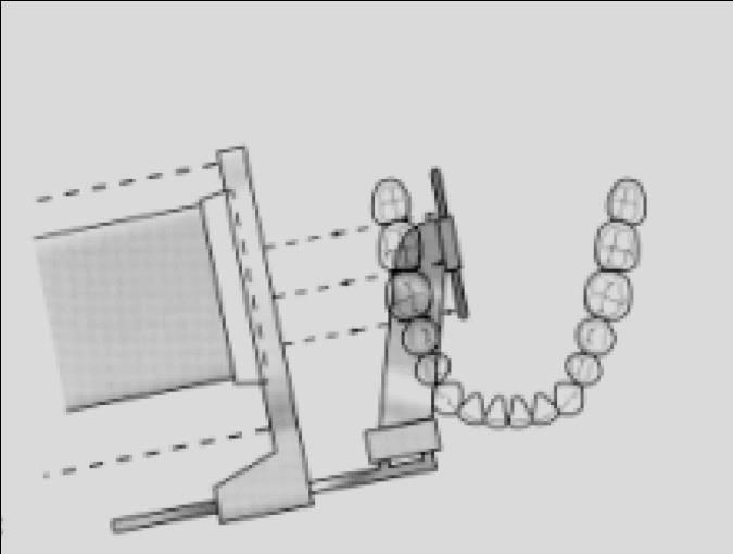
2 A full mouth radiographic series (FMX) consists of 20 images composed of periapical (16) and bitewing (4) projections. Periapical radiographs are intended to evaluate the periapical region of the tooth and surrounding bone. Therefore, it is essential to obtain the full length of the tooth and at least 2 mm of periapical bone. Bitewing radiographs record, on a single image, the crowns and coronal 1/3 of the interproximal bone of both arches. Bitewings are useful for detecting interproximal carious lesions, bone height, pulp chamber size and shape, pulp stones, and overhangs on interproximal restorations. It is therefore essential to position the image receptor and x-ray beam so that there is an equal distribution of both arches in the resulting radiographic image. Instrument Assembly: The Rinn XCP Instrument for a full mouth series (FMX) of x-rays consists of 3 parts: 1. 3 biteblocks for the anterior, posterior, and bitewing set-ups Indicator rods for the anterior, posterior, and bitewing set-ups Aiming rings for the anterior, posterior, and bitewing set-ups. a. The same aiming ring is used for the anterior and bitewing set-ups 4

3 Posterior RINN set up for upper right and lower left and upper left and lower right, respectively Posterior RINN set up for Upper right and left respectively 5
.")
4 Posterior RINN set up for Lower right and left respectively GENERAL RULE FOR PSP PLACEMENT IN RINN INSTRUMENTS: When you look through the aiming ring, you should ONLY see the sensitive side of the image receptor. The sensitive side is indicated by the black side of the PSP packet (see below images). 6
 plate Center the PSP plate vertically in the anterior bite block with the black dot in the groove (black dot in the")
5 Videos are available that demonstrate proper operatory set-up, Rinn instrument assembly, and scanning of PSP plates. MAXILLARY CENTRAL-LATERAL PROJECTION Use a #1 size Photostimulable Phosphor (PSP) plate Center the PSP plate vertically in the anterior bite block with the black dot in the groove (black dot in the slot) and the black side of the PSP packet towards the source of radiation. CORRECT POSITIONING OF THE PSP Center the CENTRAL-LATERAL INCISOR CONTACT on the PSP plate. Place the PSP plate as far back into the mouth as possible so that the PSP plate is as parallel as possible to the long axes of the teeth. This is accomplished by engaging the incisal edges of the incisors in the FIRST OR SECOND GROOVE of the biteblock. The first or second grooves are located on the outer edge of the biteblock (edge towards the source of radiation). Position the PSP-plate so that the appropriate contact will be open (central-lateral contact). This is accomplished by projecting the x-ray beam through the contact area/s of interest Press the holder against the MAXILLARY INCISORS FIRST, then have the patient gently bite together. NOTE: Sometimes, greater stability of the bite block may be achieved if a cotton roll is placed BETWEEN the biteblock and the MANDIBULAR TEETH before having the patient close. Slide the aiming ring down the indicator rod to approximate the skin surface before making the exposure. Resulting radiograph 1. The central-lateral contact should be centered in the image. 7
 plate Center the PSP plate vertically in the anterior biteblock with the black dot in the groove (black dot in the slot) and")
6 2. At least 2 mm of apical bone is visible above the root apex. 3. Central-lateral contact is open. MAXILLARY CANINE PROJECTION Use a #1 size Photostimulable Phosphor (PSP) plate Center the PSP plate vertically in the anterior biteblock with the black dot in the groove (black dot in the slot) and the black side of the PSP packet towards the source of radiation. CORRECT POSITIONING OF THE PSP Center the CANINE in the middle of the PSP plate. Place the PSP plate well away from the palatal surface of the teeth so that the PSP plate is as parallel as possible to the long axis of the cuspid. o This is accomplished by engaging the incisal edge of the cuspid in the FIRST or SECOND GROOVE of the biteblock. Position the PSP-plate so that the appropriate contact will be open. o This is accomplished by projecting the x-ray beam through the contact area of interest. o Note: the contact to open is the lateral-canine contact. Do not attempt to open the distal canine contact; it will be visualized on different views. Press the holder against the canine FIRST, then have the patient gently bite together. NOTE: Sometimes greater stability of the biteblock may be achieved if a cotton roll is placed BETWEEN the biteblock and the MANDIBULAR TEETH before having the patient close. Slide the aiming ring down the indicator rod to approximate the skin surface before making the exposure. 8

7 Resulting Radiograph 1. The canine should be centered in the image. 2. At least 2 mm of apical bone is visible above the root apex. 3. The lateral-canine contact is open. MAXILLARY PREMOLAR PROJECTION Use a #2 size PSP plate. Center the PSP plate HORIZONTALLY in the posterior biteblock with the black dot in the groove (black dot in the slot) and the black side of the PSP packet towards the source of radiation. CORRECT POSITIONING OF THE PSP Position the PSP plate near the midline of the palate to ensure that the PSP plate is placed as parallel as possible to the long axes of the premolars o This is accomplished by engaging the buccal cusps in the First or Second Groove of the bite block). The anterior edge of the PSP plate should be placed adjacent to the maxillary canine on 9

8 the side being radiographed so that the distal ½ of the canine will be included in the radiographic image. Position the PSP-plate so that the appropriate contacts will be open. o This is accomplished by projecting the x-ray beam through the contact areas of interest. Slide the aiming ring down the indicator rod to approximate the skin surface before making the exposure. Resulting Radiograph 1. The distal half of the canine should be visible as well as all of the first and second premolars and first molar and sometimes also the mesial half of the 2nd molar. 2. At least 2 mm of apical bone is visible above the root apex. 3. The contacts should be open. MAXILLARY MOLAR REGION Use a #2 size PSP plate. Center the PSP plate HORIZONTALLY in the posterior biteblock with the black dot in the groove (black dot in the slot) and the black side of the PSP packet towards the source of radiation. 10

9 CORRECT POSITIONING OF THE PSP Orient the PSP plate so that it is as parallel as possible to the long axes of the teeth. o This is accomplished by placing the buccal cusps of the maxillary teeth in the FIRST or SECOND GROOVE of the biteblock. o This will place the upper edge of the PSP plate at or across the midline of the palate. Position the PSP-plate so that the appropriate contacts will be open. o This is accomplished by projecting the x-ray beam through the contact areas of interest. Position the PSP plate to cover the first, second, and third molar areas. The anterior border should just cover the distal aspect of the second premolar. o Note: the mesial placement of the edge of the PSP will usually NOT include any of the 1 st premolar. Slide the aiming ring down the indicator rod to approximate the skin surface before making the exposure. Resulting Radiograph 1. Radiograph should show all of the first, second, and third molar areas. 2. At least 2 mm of apical bone is visible above the root apex. 3. The contacts should be open. 11
 and the black side of the PSP packet towards the source of radiation. CORRECT POSITIONING OF THE PSP Center the central-lateral contact in the middle of the PSP plate.")
10 MANDIBULAR CENTRAL-LATERAL PROJECTION Use a #1 size Photostimulable Phosphor (PSP) plate Center the PSP plate vertically in the anterior biteblock with the black dot in the groove (black dot in the slot) and the black side of the PSP packet towards the source of radiation. CORRECT POSITIONING OF THE PSP Center the central-lateral contact in the middle of the PSP plate. Engage the biteblock against the INCISAL EDGES of the mandibular incisors in the vicinity of the center hole. The bottom edge of the PSP plate should be placed UNDER THE TONGUE extending posteriorly into the 2nd premolar-1st molar region. Position the PSP-plate so that the appropriate contact will be open. o This is accomplished by projecting the x-ray beam through the contact area of interest. ROTATE the PSP plate DOWNWARD into the floor of the mouth until it is as parallel as possible to the long axes of the incisors. Press lightly downward and backward on the PSP plate and biteblock to ensure that the holder maintains continuous contact with the incisal edges. Note: sometimes greater stability can be accomplished by placing a cotton roll BETWEEN the top of the biteblock and the MAXILLARY TEETH before having the patient close. Slide the aiming ring down the indicator rod to approximate the skin surface before making the exposure. Resulting Radiograph 1. The central-lateral contact should be centered in the image. 2. At least 2 mm of apical bone is visible below the root apex. 3. The central-lateral contact is open. 12

11 MANDIBULAR CANINE PROJECTION Use a #1 size Photostimulable Phosphor (PSP) plate Center the PSP vertically in the anterior biteblock with the black dot in the groove (black dot in the slot) and the black side of the PSP packet towards the source of radiation. CORRECT POSITIONING OF THE PSP Center the canine in the middle of the PSP plate. The PSP plate is placed under the tongue and across the midline. Engage the biteblock against the INCISAL EDGE of the mandibular canine in the vicinity of the center hole. Position the PSP-plate so that the appropriate contact will be open. o This is accomplished by projecting the x-ray beam through the contact area of interest. o Note: the contact to open is the lateral-canine contact. Do not attempt to open the distal canine contact; it will be visualized on different views. ROTATE the PSP plate DOWNWARD into the floor of the mouth until it is as parallel as possible to the long axis of the canine. Press lightly downward and backward on the PSP plate holder to ensure that the biteblock maintains continuous contact with the incisal edge of the canine. Note: sometimes greater stability can be achieved by placing a cotton roll BETWEEN the top of the biteblock and the MAXILLARY TEETH before having the patient close. Slide the aiming ring down the indicator rod to approximate the skin surface before making the exposure. 13

12 Resulting Radiograph 1. The canine should be centered in the image. 2. At least 2 mm of apical bone is visible below the apex. 3. The lateral-canine contact is open MANDIBULAR PREMOLAR REGION Use a #2 size PSP plate. Center the PSP plate HORIZONTALLY in the posterior bite block with the black dot in the groove (black dot in the slot) and the black side of the PSP packet towards the source of radiation. CORRECT POSITIONING OF THE PSP Insert the PSP plate and holder into the mouth and carry it past the central incisors to a point where the anterior edge of the PSP plate is adjacent to the mandibular canine on the side being radiographed. Adjust the PSP plate DOWNWARD past the lateral border of the tongue so that the bottom edge of the PSP plate will pass BETWEEN THE TEETH AND THE TONGUE. o Displace the PSP plate medially (toward the middle of the tongue) to make sure the bottom edge is not pressing against the muscle attachment for the floor of the mouth. The biteblock should rest on the MANDIBULAR occlusal surfaces near the center hole. The PSP plate should also be positioned parallel to the lingual surface of the mandibular 14

13 teeth. Position the PSP plate so that the appropriate contacts will be open. o This is accomplished by projecting the x-ray beam through the contact areas of interest. Ask the patient to gently close together and stabilize the holder, if necessary, with a cotton roll between the biteblock and the MAXILLARY TEETH. Slide the aiming ring down the indicator rod to approximate the skin surface before making the exposure. Resulting Radiograph 1. Radiograph should show the distal half of the cuspid, all of the first and second premolars, the first molar, and sometimes the mesial half of the 2nd molar. 2. At least 2 mm of apical bone is visible below the root apex. 3. The contacts should be open. MANDIBULAR MOLAR REGION Use a #2 size PSP plate. Center the PSP plate HORIZONTALLY in the posterior biteblock with the black dot in the groove (black dot in the slot) and the black side of the PSP packet towards the source of radiation. CORRECT POSITIONING OF THE PSP Insert the PSP plate and holder into the mouth and carry it past the central incisors to a point 15

14 where the anterior edge of the PSP plate is adjacent to the mandibular second premolar on the side being radiographed. Adjust the PSP plate DOWNWARD past the lateral border of the tongue so that the bottom edge will pass BETWEEN THE TEETH AND THE TONGUE. The bite block should rest on the MANDIBULAR occlusal surfaces near the center hole. Position the PSP-plate so that the appropriate contacts will be open. o This is accomplished by projecting the x-ray beam through the contact areas of interest. Ask the patient to gently close together and stabilize the biteblock, if necessary, with a cotton roll between the biteblock and the MAXILLARY TEETH. Slide the aiming ring down the indicator rod to approximate the skin surface before making the exposure. Resulting Radiograph 1. Radiograph should show the first, second and third molar areas. 2. At least 2 mm of apical bone is visible below the root apex. 3. The contacts should be open. PREMOLAR BITEWING PROJECTION (horizontal technique) Use a #2 size PSP plate. Center the PSP plate in the bitewing biteblock with the black side of the PSP packet towards the source of radiation. 16
15 CORRECT POSITIONING OF THE PSP Position the PSP plate so that its mesial edge will include the distal half of the mandibular canine. Holding onto the edge of the positioning device, place the biteblock in contact with the MANDIBULAR TEETH. Horizontally, position the PSP plate so that the x-ray beam is directed through the mandibular contacts. o There may be some difference in the curvature of the mandibular and maxillary arches. However, when the x-ray beam is accurately directed through the mandibular premolar contacts, overlapping is minimal or absent in the maxillary premolar segment. o Typically this projection requires a +10 angle of the BID (with the patient s occlusal plane parallel to the floor). Make sure that the PSP plate is BETWEEN the lingual surfaces of the teeth and the lateral border of the tongue. Slide the aiming ring down the indicator rod to approximate the skin surface before making the exposure. Resulting radiograph 1. Radiograph should show an equal distribution of both arches. 2. The distal half of the maxillary and mandibular canines should be visible as well as the 1 st and 2 nd premolars, 1 st molars and occasionally the second molars. 3. The contacts should be open 17
. Horizontally, project the x-ray beam through the contact areas of interest.")
16 MOLAR BITEWING PROJECTION (horizontal technique) Place the PSP plate between the tongue and the teeth and far enough posteriorly to include the distal of the last erupted tooth in the arch. Typically this projection requires a +10 angle of the BID (with the patient s occlusal plane parallel to the floor). Horizontally, project the x-ray beam through the contact areas of interest. It is helpful to align the indicator rod with the maxillary contacts. Resulting Radiograph 1. Radiograph should show an equal distribution of both arches. 2. Radiograph should include the distal of the last erupted tooth in the arch. 3. The contacts should be open. 4. It is preferable to see the distal surfaces of the maxillary and mandibular second premolars. 18
17 19

18 GRU RADIOGRAPHIC TECHNIQUE MAXILLARY ANTERIOR EXPOSURE Anterior Rinn Instrument, Use #1 PSP plate, place black dot in the slot, black side towards ring Patient s Mouth Open Center area of interest on biteblock Lean biteblock so that teeth are in 1 st or 2 nd groove If needed, place cotton roll under the biteblock touching the incisal edges of mandibular anterior teeth Patient s mouth closes Slide the aiming ring down the indicator rod to approximate the skin surface Place cone flush with ring and make exposure 20

19 MANDIBULAR ANTERIOR EXPOSURE Anterior Rinn Instrument Use #1 PSP plate, place black dot in the slot, black side towards ring Patient s Mouth Open Center area of interest on biteblock Lean biteblock so that teeth are in middle groove If needed, place cotton roll on top of the biteblock touching the maxillary teeth Patient s mouth closes Slide the aiming ring down the indicator rod to approximate the skin surface Place cone flush with ring and make exposure 21

20 MAXILLARY POSTERIOR EXPOSURE Posterior Rinn Instrument, Use #2 PSP plate, Place PSP plate horizontally in biteblock, place black dot in the slot, place black side towards ring Patient s Mouth Open Center area of interest on bite block Lean biteblock so that teeth are in 1 st or 2 nd groove Make PSP plate parallel to lingual of teeth If needed, place cotton roll below the biteblock touching the occlusal surfaces of mandibular posterior teeth Patient s mouth closes Slide the aiming ring down the indicator rod to approximate the skin surface Place cone flush with ring and make exposure 22

21 MANDIBULAR POSTERIOR EXPOSURE Posterior Rinn Instrument, Use #2 PSP plate, Place PSP plate horizontally in biteblock, place black dot in the slot, place black side towards ring Patient s Mouth Open Center area of interest on biteblock Lean biteblock so that teeth are in middle groove Make PSP plate parallel to lingual of teeth If needed, place cotton roll against occlusal surfaces of maxillary teeth Patient s mouth closes Slide the aiming ring down the indicator rod to approximate the skin surface Place cone flush with ring and make exposure 23
 Align aiming arm with maxillary contacts (for molar bitewing")
22 BITEWING EXPOSURE Rinn Bitewing Instrument, Use size #2 PSP plate, place PSP plate horizontally in holder, dot does not matter, black side towards ring Patient s Mouth Open Center area of interest on biteblock Place biteblock against mandibular teeth Align aiming arm with mandibular contacts (for premolar bitewing projection) Align aiming arm with maxillary contacts (for molar bitewing projection) Patient s mouth closes 24 Slide the aiming ring down the indicator rod (aiming arm) to approximate the skin surface Place cone flush with ring and make exposure
23 QUALITY EVALUATION CRITERIA GENERAL CHARACTERISTICS OF A QUALITY RADIOGRAPH IMAGE CONTRAST, DENSITY, SHARPNESS, IDENTIFICATION Radiographic image should permit differentiation between the various structures of the teeth, the periodontal ligament space, the lamina dura, the supporting bone and normal anatomic landmarks. IMAGE COVERAGE All crowns and roots, including apices, are fully depicted together with the interproximal alveolar crests, contact areas, and surrounding bone regions. IMAGE DEFECTS Images of all teeth and other structures are shown in proper relative size and contour with minimal distortion, without overlapping images where anatomically possible, and without partial images (cone cuts). ANATOMICAL ACCURACY A properly exposed radiograph is said to have anatomical accuracy when: 1. The labial and lingual cemento-enamel junctions of the anterior teeth are superimposed. 2. The buccal and lingual cusps of posterior teeth (especially the molars) are superimposed. 3. The contacts of the teeth are opened in at least one of the projections of a given area. 4. The buccal portion of the alveolar crest is superimposed over the lingual portion of the alveolar crest. 5. There is no superimposition of the zygomatic bone over the roots of the maxillary molar teeth. 25

24 EACH SPECIFIC REGION OF THE FMX SHOULD INCLUDE THE FOLLOWING: Maxillary molar area All crowns and roots of the maxillary molars including the apices are fully depicted together with the interproximal alveolar crests, contact areas and surrounding bone region. There is no superimposition of the lower border of the zygomatic bone over the roots of maxillary molars. The radiograph should include all of the first, second, and third molars (erupted or not) with open interproximal spaces. Maxillary premolar area All the crowns and roots of the maxillary premolars and first molar, including the apices, are fully depicted together with interproximal alveolar crests, contact areas and surrounding bone. In the maxillary premolar projection the distal surface (distal 1/2) of the canine must be seen. The contacts should be open. Maxillary canine area All of the crown and root of the maxillary canine, including the apex, is fully depicted together with the interproximal alveolar crest between the maxillary canine and the maxillary lateral incisor, the contact area and surrounding bone region. The lateral incisor - canine contact should be open but it is not necessary for the distal surface of the maxillary canine to be seen. The canine should be centered. 26

25 Maxillary central - lateral incisor area The central-lateral contact should be centered and open. The crowns and roots should be visible with at least 2 mm of bone visible beyond the apex. Mandibular molar area All crowns and roots, including apices, of all three mandibular molars, are fully depicted together with interproximal alveolar crests, contact areas and surrounding bone regions. Contacts should be open. Mandibular premolar area All the crowns and roots of the mandibular premolars, including the apices, are fully depicted together with interproximal alveolar crests, contact areas and surrounding bone regions. The distal surface (distal1/2) of the canine should be seen in this projection. Contacts should be open. 27

26 Mandibular canine area All of the crown and the root of the mandibular canine, including the apex, is fully depicted together with the interproximal alveolar crests and contact area between the mandibular lateral incisor and mandibular canine, and surrounding bone region. The canine should be centered. Lateral-canine contact should be open. Mandibular central - lateral incisor area All crowns and roots, including apices, of the central and lateral incisors, are fully depicted together with interproximal alveolar crests, contact areas and surrounding bone regions. The central - lateral incisor contact should be centered in the radiograph and should be open. Premolar bitewing All crowns of the maxillary and mandibular premolars are fully depicted together with the interproximal crests and contact areas. The distal surfaces of the maxillary and mandibular canines must be seen. The images are without horizontal overlap where anatomically possible. 28

27 Molar bitewing All crowns of the maxillary and mandibular molars are fully depicted together with the interproximal crests and contact areas. It is preferable to see the distal surfaces of the maxillary and mandibular second premolar teeth. The images are without horizontal overlap where anatomically possible. The distal of the last erupted tooth is visible. RADIOGRAPHIC MOUNTING PROCEDURES Mounting intraoral radiographs is a relatively simple procedure provided you have some knowledge of the normal radiographic anatomical landmarks for each region of the mouth and can recognize tooth morphology. Maxillary posterior regions: All maxillary posterior radiographs should be arranged so that the crowns of the teeth are toward the bottom of the computer screen and roots are towards the top (the same way they are positioned within the patient). If no radiographs were exposed backwards, once the maxillary posterior radiographs are oriented with the crowns downward, it will be necessary only to identify mesial or distal anatomic landmarks of teeth in order to distinguish right from left. Radiographs with the more mesial structures are mounted in the premolar position; those with more distal landmarks are mounted in the molar positions. Maxillary anterior region: Identify the four maxillary anterior radiographs and rotate the incisal portion of each image down toward the bottom of the computer screen (same as for maxillary posterior region). Use the anatomic landmarks of the nasal cavity, soft tissue of the nose, and maxillary sinus to help you distinguish between the maxillary and mandibular anterior periapical radiographs. Identify the maxillary central - lateral incisor radiographs and mount them in the center windows of the anterior section of the mount; next identify the R and L canine radiographs and mount them with mesial anatomic structures always directed toward the middle of the mount. 29

28 Mandibular posterior regions: Identify the four (4) posterior mandibular radiographs. Rotate these radiographs around until the coronal portion of the radiograph is directed toward the top of the computer screen. Identify mesial and distal structures and arrange in appropriate areas of the mount. Mandibular anterior region: Rotate the four mandibular anterior radiographs until their incisal edges are directed toward the top of the screen; identify the central - lateral incisor regions and mount them into the center windows of the mount. Next mount the canine projections. Bitewings: The remaining four radiographs are interproximal radiographs. Orient these radiographs with the curve of Spee (occlusal plane between maxillary and mandibular teeth) directed upward toward the distal. If the occlusal plane is flat attempt to identify characteristics of the respective crowns or frequently the bifurcation of the mandibular molar is distinguishable and may serve as a valuable aid in distinguishing mandibular from maxillary teeth. Once the appropriate arch can be identified the radiographs can be properly oriented with the most mesial structures used to identify right from left and premolar from molar regions. PATIENT'S RIGHT PATIENT'S LEFT Ex. mounted FMX 30
Bitewing Radiography B.E. DIXON. B.D.S., M.Sc., D.P.D.S.
 Bitewing Radiography B.E. DIXON B.D.S., M.Sc., D.P.D.S. Main Indications Detection of Dental Caries Monitoring progression of caries Assessment of existing restorations Assessment of Periodontal status
Periapical radiography
 8 Periapical radiography Periapical radiography describes intraoral techniques designed to show individual teeth and the tissues around the apices. Each film usually shows two to four teeth and provides
Intraoral Radiographic Techniques
 Intraoral Radiographic Techniques Allan G. Farman, BDS, EdS., MBA, PhD; Sandra A. Kolsom, CDA-Emeritus, RDA; ADAA 2014 Council on Education Continuing Education Units: 4 hours Online Course: www.dentalcare.com/en-us/dental-education/continuing-education/ce119/ce119.aspx
Introduction to Dental Anatomy
 Introduction to Dental Anatomy Vickie P. Overman, RDH, MEd Continuing Education Units: N/A This continuing education course is intended for dental students and dental hygiene students. Maintaining the
Dental Radiography collimator Ionising radiation image radiolucent area radiopaque area controlled zone scatter radiation intraoral
 Dental Radiography X-rays for dental radiography are produced by high voltages of electricity within an x-ray head and come out through a metal tube called a collimator. This ensures the x-rays only come
In Class IV arch: Fulcrum line passes through two abutments adjacent to single edentulous space.
 It is that part of removable partial denture which assists the direct retainers in preventing displacement of distal extension denture bases by resisting lever action from the opposite side of the fulcrum
Classification of Malocclusion
 Classification of Malocclusion What s going on here? How would you describe this? Dr. Robert Gallois REFERENCE: Where Do We Begin? ESSENTIALS FOR ORTHODONTIC PRACTICE By Riolo and Avery Chapter 6 pages
Simplified Positioning for Dental Radiology
 Simplified Positioning for Dental Radiology Prepared by: Animal Dental Care Tony M. Woodward DVM, Dipl. AVDC 5520 N. Nevada Ave. Suite 150 Colorado Springs, CO 80918 (719) 536-9949 [email protected] www.wellpets.com
CHAPTER 10 RESTS AND PREPARATIONS. 4. Serve as a reference point for evaluating the fit of the framework to the teeth.
 CHAPTER 10 RESTS AND DEFINITIONS A REST is any rigid part of an RPD framework which contacts a properly prepared surface of a tooth. A REST PREPARATION or REST SEAT is any portion of a tooth or restoration
Full Crown Module: Learner Level 1
 Full Crown Module Restoration / Tooth # Full Gold Crown (FGC) / 30 Extensions: Porcelain Fused to Metal (PFM) / 12 All Ceramic / 8 Learner Level 1 Mastery of Tooth Preparation Estimated Set Up Time: 30
porcelain fused to metal crown
 Lectur.5 Dr.Adel F.Ibraheem porcelain fused to metal crown the most widely used fixed restoration,it is full metal crown having facial surface (or all surfaces) covered by ceramic material. It consist
Molar Uprighting Dr. Margherita Santoro Division of Orthodontics School of Dental and Oral surgery. Consequences of tooth loss.
 Molar Uprighting Dr. Margherita Santoro Division of Orthodontics School of Dental and Oral surgery Molars The wide occlusal surface is designed for food grinding. The surface needs to be aligned with the
DEVELOPMENT AND GROWTH OF THE MANDIBLE
 2012-2013 ORAL BIOLOGY DEVELOPMENT AND GROWTH OF THE MANDIBLE Ass. Prof. Dr. Heba M. Elsabaa Development and Growth of the Mandible DEVELOPMENT OF THE MANDIBLE The Mandible Is the largest and strongest
ABSTRACT INTRODUCTION. Facial Esthetics. Dental Esthetics
 ABSTRACT The FACE philosophy is characterized by clearly defined treatment goals. This increases diagnostic ability and improves the quality and stability of the end result. The objective is to establish
Headgear Appliances. Dentofacial Orthopedics and Orthodontics. A Common Misconception. What is Headgear? Ideal Orthodontic Treatment Sequence
 Ideal Orthodontic Treatment Sequence Headgear Appliances Natalie A. Capan, D.M.D. 580 Sylvan Avenue, Suite 1M Englewood Cliffs, New Jersey 07632 (201)569-9055 www.capanorthodontics.com [email protected]
CLASSIFICATION OF CARIOUS LESIONS AND TOOTH PREPARATION.
 CLASSIFICATION OF CARIOUS LESIONS AND TOOTH PREPARATION. ١ G.V. BLACK who is known as the father of operative dentistry,he classified carious lesions into groups according to their locations in permanent
Implants in your Laboratory: Abutment Design
 1/2 point CDT documented scientific credit. See Page 41. Implants in your Laboratory: Abutment Design By Leon Hermanides, CDT A patient s anatomical limitations have the greatest predictive value for successful
Prosthodontist s Perspective
 Unless otherwise noted, the content of this course material is licensed under a Creative Commons Attribution - Non-Commercial - Share Alike 3.0 License. Copyright 2008, Dr. Jeff Shotwell. The following
CLASSIFICATION OF REMOVABLE PARTIAL DENTURES
 Unless otherwise noted, the content of this course material is licensed under a Creative Commons Attribution - Non-Commercial - Share Alike 3.0 License. Copyright 2008, Dr. Jeff Shotwell. The following
LESSON ASSIGNMENT. Topography of the Mouth and Tooth Structure. After completing this lesson, you should be able to:
 LESSON ASSIGNMENT LESSON 3 Topography of the Mouth and Tooth Structure. LESSON ASSIGNMENT Paragraphs 3-1 through 3-9. LESSON OBJECTIVES After completing this lesson, you should be able to: 3-1. Identify
NEW YORK CITY COLLEGE OF TECHNOLOGY
 NEW YORK CITY COLLEGE OF TECHNOLOGY THE CITY UNIVERSITY OF NEW YORK DEPARTMENT OF RESTORATIVE DENTISTRY DEPARTMENT: COURSE CODE: COURSE TITLE: COURSE DESCRIPTION: CLASS HOURS & CREDITS: NUMBER OF WEEKS:
Treatment planning for the class 0, 1A, 1B dental arches
 Treatment planning for the class 0, 1A, 1B dental arches Dr.. Peter Hermann Dr Reminder: Torquing movement on tooth supported denture : no movement Class 1 movement in one direction (depression) Class
Put Your Panoramic Imaging on Steroids While Reducing the Patient s Dose!
 Put Your Panoramic Imaging on Steroids While Reducing the Patient s Dose! Dale A. Miles BA, DDS, MS, FRCD(C) Diplomate, American Board of Oral and Maxillofacial Radiology It used to be that panoramic images
A. DEVELOPMENT OF THE DENTAL ORGAN (ENAMEL ORGAN):
:") A. DEVELOPMENT OF THE DENTAL ORGAN (ENAMEL ORGAN): AS EARLY AS THE SECOND MONTH OF FETAL LIFE, THE DEVELOPMENT OF THE DECIDUOUS TEETH MAY FIRST BECOME EVIDENT. 1. Dental lamina and Bud stage At about six
A. DEVELOPMENT OF THE DENTAL ORGAN (ENAMEL ORGAN): AS EARLY AS THE SECOND MONTH OF FETAL LIFE, THE DEVELOPMENT OF THE DECIDUOUS TEETH MAY FIRST BECOME EVIDENT. 1. Dental lamina and Bud stage At about six
ATLANTIS abutments design guide CAD/CAM patient-specific abutments
 ATLANTIS abutments design guide CAD/CAM patient-specific abutments Contents Introduction 4 This manual helps you to explore all the benefits of ATLANTIS CAD/CAM patient-specific abutments. It gives you
Healing Abutment Selection. Perio Implant Part I. Implant Surface Characteristics. Single Tooth Restorations. Credit and Thanks for Lecture Material
 Healing Abutment Selection Perio Implant Part I Credit and Thanks for Lecture Material Implant Surface Characteristics!CAPT Robert Taft!CAPT Greg Waskewicz!Periodontal Residents NPDS and UMN!Machined Titanium!Tiunite!Osseotite
Introduction to Charting. Tooth Surfaces: M = mesial D = distal O = Occlusal B = buccal F = facial I = incisal L = lingual
 Tooth Surfaces: M = mesial D = distal O = Occlusal B = buccal F = facial I = incisal L = lingual When combining tooth surfaces, as in defining cavity preparations or restorations, there are some spelling
Denture Trouble Shooting Guide
 Denture Trouble Shooting Guide Comfort Sore spot in vestibuleupper or lower denture 1. Overextended borders 2. Rough spot in base 1. Shorten borders and polish. 2. Refinish borders. Sore spot in upper
IMPLANT DENTISTRY EXAM BANK
 IMPLANT DENTISTRY EXAM BANK 1. Define osseointegration. (4 points, 1/4 2. What are the critical components of an acceptable clinical trial? (10 points) 3. Compare the masticatory performance of individuals
Principles of Partial Denture Design
 Principles of Partial Denture Design 1. Keep the RPD design as simple as possible Simple those design elements which promote function, esthetics, comfort, ease of fabrication, and ease of maintenance,
Full Crown Module: Learner Level 3
 Full Crown Module Restoration / Tooth # Full Gold Crown (FGC) / mesially tilted 30 Extensions: Porcelain Fused to Metal (PFM) / lingually 21 All Ceramic / rotated 12 Learner Level 3 Preparation of Malpositioned
A collection of pus. Usually forms because of infection. A tooth or tooth structure which is responsible for the anchorage of a bridge or a denture.
 Abscess A collection of pus. Usually forms because of infection. Abutment A tooth or tooth structure which is responsible for the anchorage of a bridge or a denture. Amalgam A silver filling material.
Tooth preparation J. C. Davenport, 1 R. M. Basker, 2 J. R. Heath, 3 J. P. Ralph, 4 P-O. Glantz, 5 and P. Hammond, 6
 12 5 Tooth preparation J. C. Davenport, 1 R. M. Basker, 2 J. R. Heath, 3 J. P. Ralph, 4 P-O. Glantz, 5 and P. Hammond, 6 This final article in the series describes the modification of teeth to improve
Dental Radiology Related With Pedodontics
 Dental Radiology Related With Pedodontics Presented by: Dr. Rajeev Kumar Singh Radiology The branch of medicine that deals with the use of X- rays and radioactive substances in the diagnosis and treatment
Introduction of Removable Partial Denture - Design and Retention
 Introduction of Removable Partial Denture - Design and Retention By : Dr Zaihan Ariffin BDS(Malaya), GDCDent (Adelaide), Doctor of Clinical Dentistry (Adelaide), FRACDS (Australia) Type of denture Full
Humana Health Plans of Florida. Important:
 Humana Health Plans of Florida Important: Dental discount membership in Florida is determined by viewing the member s ID card and verifying that the Humana Logo and Medicare name is listed with an effective
The Obvious and the Obscure:Diagnostic Steps for Crack Confirmation
 Cracking the Cracked Tooth Code In response to your requests... At the end of each issue of ENDODONTICS: Colleagues for Excellence, the American Association of Endodontists (AAE) asks readers to send in
Dental Anatomy: A Review
 Dental Anatomy: A Review Antoinette Metivier, CDA; Kimberly Bland, CDA, EFDA, M.Ed. Continuing Education Units: 2 hours Disclaimer: Participants must always be aware of the hazards of using limited knowledge
MEDICAID DENTAL PROGRAMS CODING, POLICY AND RELATED FEE REVISION INFORMATION
 MEDICAID DENTAL PROGRAMS CODING, POLICY AND RELATED FEE REVISION INFORMATION Effective for dates of service on and after November 1, 2005, the following dental coding, policy and related fee revisions
Maxillary Sinus. (Antrum of Higmore)
") Maxillary Sinus (Antrum of Higmore) The maxillary sinus is a pneumatic space. It is the largest bilateral air sinus located in the body of the maxilla and opens in the middle nasal meatus of the nasal
Maxillary Sinus (Antrum of Higmore) The maxillary sinus is a pneumatic space. It is the largest bilateral air sinus located in the body of the maxilla and opens in the middle nasal meatus of the nasal
Universal Crown and Bridge Preparation
 Universal Crown and Bridge Preparation The All-Ceramic Crown Preparation Technique for Predictable Success According to Dr. Ronald E. Goldstein Expect the Best. Buy Direct. The Universal * Crown and Bridge
Radiation safety in dental radiography
 Radiation safety in dental radiography Kodak s dental radiograph series The goal of dental radiography is to obtain diagnostic information while keeping the exposure to the patient and dental staff at
Table of Contents Section 6 Table of Contents
 Table of Contents Section Table of Contents Victory Series First Molar Bands...2 Victory Series Second Molar Bands... Unitek General Purpose Molar Bands...10 Unitek Pedodontic Molar Bands...11 Unitek Proportioned
Postendodontic Tooth Restoration - Part I: The Aim and the Plan of. the procedure.
 Postendodontic Tooth Restoration - Part I: The Aim and the Plan of the Procedure Sanja egoviê 1 Nada GaliÊ 1 Ana Davanzo 2 Boæidar PaveliÊ 1 1 Department of Dental Pathology School of Dental Medicine University
Veraviewepocs 3D R100 & F40
 Veraviewepocs 3D R100 & F40 Innovative 3D Reuleaux Full Arch FOV Thinking ahead. Focused on life. Veraviewepocs 3D R100 A New Frontier in X-ray Diagnostics Veraviewepocs 3D R100 has changed the shape of
Veraviewepocs 3D R100 & F40
 Veraviewepocs 3D R100 & F40 Innovative 3D Reuleaux Full Arch FOV Thinking ahead. Focused on life. Veraviewepocs 3D R100 A New Frontier in X-ray Diagnostics Veraviewepocs 3D R100 has changed the shape of
Case Report(s): Uncomplicated Crown Fractures
: Uncomplicated Crown Fractures") Case Report(s): Uncomplicated Crown Fractures Tooth fractures can be classified as follows: Uncomplicated crown fracture = fracture limited to the crown of the tooth with dentin exposure but no pulp exposure.
Case Report(s): Uncomplicated Crown Fractures Tooth fractures can be classified as follows: Uncomplicated crown fracture = fracture limited to the crown of the tooth with dentin exposure but no pulp exposure.
Page 1 of 10 BDS FINAL PROFESSIONAL EXAMINATION 2007 Prosthodontics (MCQs) Model Paper SECTION I
 Model Paper SECTION I") Page 1 of 10 COMPLETE DENTURES ANATOMICAL LANDMARKS SECTION I 1. There are many landmarks in the oral cavity which helps in designing complete dentures. One of the important landmarks is fovea palatini.
Page 1 of 10 COMPLETE DENTURES ANATOMICAL LANDMARKS SECTION I 1. There are many landmarks in the oral cavity which helps in designing complete dentures. One of the important landmarks is fovea palatini.
Radiation safety in dental radiography
 Radiation safety in dental radiography Dental Radiography Series The goal of dental radiography is to obtain diagnostic information while keeping the exposure to the patient and dental staff at minimum
The American Board of Orthodontics (ABO) Digital Model Requirements Original Release 04.23.2013 Last Update 03.26.2015
 Digital Model Requirements Original Release 04.23.2013 Last Update 03.26.2015") Page 1 of 7 The American Board of Orthodontics (ABO) Digital Model Requirements Original Release 04.23.2013 Last Update 03.26.2015 Introduction In order to provide access to board certification for all
Page 1 of 7 The American Board of Orthodontics (ABO) Digital Model Requirements Original Release 04.23.2013 Last Update 03.26.2015 Introduction In order to provide access to board certification for all
Anatomic Anomalies. Anomalies. Anomalies. Anomalies. Supernumerary Teeth. Supernumerary Teeth. Steven R. Singer, DDS 212.305.5674 srs2@columbia.
 Anatomic Anomalies Steven R. Singer, DDS 212.305.5674 [email protected] Anomalies! Anomalies are variations in the:! Size! Morphology! Number! Eruption of the teeth Anomalies Anomalies There are two categories:!
Powertome Assisted Atraumatic Tooth Extraction
 Powertome Assisted Atraumatic Tooth Extraction White et al Jason White, DDS 1 2 3 Abstract Background: While traditional dental extraction techniques encourage minimal trauma, luxated elevation and forceps
Managing worn teeth with composites
 6 Managing worn teeth with composites Clinical details A 50-year-old man presents to you complaining about his worn teeth and would like the appearance improved (Fig. 6.1). He complains of regurgitation
Replacement of the upper left central incisor with a Straumann Bone Level Implant and a Straumann Customized Ceramic Abutment
 Replacement of the upper left central incisor with a Straumann Bone Level Implant and a Straumann Customized Ceramic Abutment by Dr. Ronald Jung and Master Dental Technician Xavier Zahno Initial situation
Nobel Clinician - Quick Guide
 1220 E. Birch St. #201 Brea, CA 92821 (800)750-5004 Haupt Dental Lab Inc. Nobel Clinician - Quick Guide Step #1 - Diagnostics Make impressions of both the upper and lower arches using custom trays. Care
Calibrated Periodontal Probes and Basic Probing Technique
 Module 11 Calibrated Periodontal Probes and Basic Probing Technique MODULE OVERVIEW This module presents the (1) design characteristics of calibrated periodontal probes and (2) step-by-step instructions
Removable appliances II. Functional jaw orthopedics
 Removable appliances II. Functional jaw orthopedics Melinda Madléna DMD, PhD Associate professor Department of Pedodontics and Orthodontics Faculty of Dentistry Semmelweis University Budapest Classification
4-1-2005. Dental Clinical Criteria and Documentation Requirements
 4-1-2005 Dental Clinical Criteria and Documentation Requirements Table of Contents Dental Clinical Criteria Cast Restorations and Veneer Procedures... Pages 1-3 Crown Repair... Page 3 Endodontic Procedures...
Another Implant Option for Missing Teeth with Challenging Symmetry Patrick Gannon, DDS and Luke Kahng, CDT
 Another Implant Option for Missing Teeth with Challenging Symmetry Patrick Gannon, DDS and Luke Kahng, CDT Introduction A 58 year old male had been missing teeth #7=12 for approximately 28 years. During
CLASS II AMALGAM. Design Principles
 CLASS II AMALGAM Design Principles CLASS II Class II cavitated caries lesions Class II cavitated caries lesions opaque white haloes identify areas of enamel undermining and decalcification from within
SURGICAL MANUAL. Step By Step Techniques
 SURGICAL MANUAL Step By Step Techniques TABLE OF CONTENTS PRE-SURGICAL 1 8 MEASUREMENT OF BONE.......................... 2 BONE CLASSIFICATION........................... 3 IMPLANT SIZE SELECTION.........................
Development of Teeth
 Development of Teeth Dr. Khaldoun Darwich Specialist in Oral and Maxillo-Facial Surgery Hamburg University PhD Hamburg University Academic Teacher - Department of OMF Surgery in Damascus University Instructor
Resorptive Changes of Maxillary and Mandibular Bone Structures in Removable Denture Wearers
 Resorptive Changes of Maxillary and Mandibular Bone Structures in Removable Denture Wearers Dubravka KnezoviÊ-ZlatariÊ Asja»elebiÊ Biserka LaziÊ Department of Prosthodontics School of Dental Medicine University
Clinical Practice Guideline For Orthodontics
 Clinical Practice Guideline For Orthodontics MOH- Oral Health CSN -Orthodontics -2010 Page 1 of 15 Orthodontic Management Guidelines 1. Definitions: Orthodontics is the branch of dentistry concerned with
OCCLUSION IN COMPLETE DENTURES
 1 OCCLUSION IN COMPLETE DENTURES C P Owen Introduction Occlusion has been described as the most important subject in all the disciplines of dentistry, and for good reason, because the way the teeth come
Objectives. Objectives. Objectives. Objectives. Describe Class II div 1
 Class II div 1 Malocclusion Class II div 1 Malocclusion Objectives OR What can we do about Goofy? Objectives Describe Class II div 1 Objectives Describe Class II div 1 Describe principles of treatment
CHAPTER 12 SURVEY LINES. portion of the tooth is undercut to the path of placement of the denture. DEFINITIONS
 CHAPTER 12 portion of the tooth is undercut to the path of placement of the denture. SURVEY LINES DEFINITIONS A SURVEY LINE is a line produced on a cast by a surveyor or scribe marking the greatest prominence
CRACKED TOOTH SYNDROME
 CRACKED TOOTH SYNDROME Dr Vijay Salvi We all come across apparently healthy teeth eliciting complex and often bizarre symptoms. The patient will give a long history of undiagnosed but severe pain, and
Introduction to Veterinary Dental Radiology. Animal Dental Care
 Introduction to Veterinary Dental Radiology Presented by: Animal Dental Care Tony M. Woodward DVM, Dipl. AVDC 5520 N. Nevada Ave. Suite 150 Colorado Springs, CO 80918 (719) 536-9949 [email protected] www.wellpets.com
Congenital absence of mandibular second premolars
 CLINICIAN S CORNER Congenitally missing mandibular second premolars: Clinical options Vincent G. Kokich a and Vincent O. Kokich b Seattle, Wash Introduction: Congenital absence of mandibular second premolars
Cysts of the Jaws. Cyst. Types. Effects on adjacent structures. Non-Odontogenic cysts. Odontogenic Cysts
 Cyst A Cyst is a benign pathologic cavity filled with fluid, lined by epithelium, and surrounded by a connective tissue wall A = connective tissue wall Cysts of the Jaws B = epithelium Effects on adjacent
Radiation Safety for Dental Auxiliaries Dr. Bruno Correa de Azevedo
 Radiation Safety for Dental Auxiliaries Dr. Bruno Correa de Azevedo Course Content 1. Radiation History and the Use of Radiographs 2. Introduction to Physics 3. X-ray Machine and Production of X-Rays 4.
Three-Dimensional Analysis Using Finite Element Method of Anterior Teeth Inclination and Center of Resistance Location
 Three-Dimensional Analysis Using Finite Element Method of Anterior Teeth Inclination and Center of Resistance Location Allahyar GERAMY 1, Ahmad SODAGAR 1, Mehdi HASSANPOUR 1 Objective: To locate the centre
Activity: Can You Identify the Age?
 Activity: Can You Identify the Age? Skeletons are good age markers because teeth and bones mature at fairly predictable rates. How Teeth Reveal Age For toddler to age 21, teeth are the most accurate age
PREPARATION OF MOUTH FOR REMOVABLE PARTIAL DENTURES Dr. Mazen kanout
 PREPARATION OF MOUTH FOR REMOVABLE PARTIAL DENTURES Dr. Mazen kanout Mouth preparation includes procedures in four categories: 1. Oral Surgical Preparation. 2. Conditioning of Abused and Irritated Tissue.
Attachments And Their Use In Removable Partial Denture Fabrication
 Unless otherwise noted, the content of this course material is licensed under a Creative Commons Attribution - Non-Commercial - Share Alike 3.0 License. Copyright 2008, Dr. Jeff Shotwell. The following
Intraoral Radiography: Positioning and Radiation Protection. A Peer-Reviewed Publication Written by Gail F. Williamson, RDH, MS
 Earn 4 CE credits This course was written for dentists, dental hygienists, and assistants. Intraoral Radiography: Positioning and Radiation Protection A Peer-Reviewed Publication Written by Gail F. Williamson,
SURGICAL EXTRACTIONS: TECHNIQUE AND CAUTIONS By Tony M. Woodward, DVM, AVDC
 SURGICAL EXTRACTIONS: TECHNIQUE AND CAUTIONS By Tony M. Woodward, DVM, AVDC We continue describing the five basic dental services that all general practitioners should be able to provide for their patients.
healthy teeth healthy body arkansas medicaid s dental care for adults
 healthy teeth healthy body arkansas medicaid s dental care for adults eeping your teeth healthy can help your whole body stay well. If your mouth and teeth are clean, you might not get sick as much. That
Appropriate soft tissue closure represents a critical
 Periosteoplasty for Soft Tissue Closure and Augmentation in Preprosthetic Surgery: A Surgical Report Albino Triaca, Dr Med, Dr Med Dent 1 /Roger Minoretti, Dr Med, Dr Med Dent 1 / Mauro Merli, DMD 2 /Beat
Page 1 of 11 BDS FINAL PROFESSIONAL EXAMINATION 2007 OPERATIVE DENTISTRY (MCQs) Model Paper
 Model Paper") Page 1 of 11 Marks 45 Time 45 minutes Total No. of MCQs 45 One mark for each 01. Hand cutting instruments are composed of: A. Handle and neck. B. Handle and blade only. C. Handle, shank and blade. D. Handle,
Page 1 of 11 Marks 45 Time 45 minutes Total No. of MCQs 45 One mark for each 01. Hand cutting instruments are composed of: A. Handle and neck. B. Handle and blade only. C. Handle, shank and blade. D. Handle,
The Treatment of Traumatic Dental Injuries
 The Recommended Guidelines of the American Association of Endodontists for The Treatment of Traumatic Dental Injuries 2013 American Association of Endodontists Revised 9/13 The Recommended Guidelines of
ORTHODONTIC SCREENING GUIDE FOR NORTH DAKOTA HEALTH TRACKS NURSES
 ORTHODONTIC SCREENING GUIDE FOR NORTH DAKOTA HEALTH TRACKS NURSES The North Dakota Department of Human Services Medical Services Division and the North Dakota Department of Health s Oral Health Program
Orthodontic mini-implants, or temporary anchorage devices
 Anchors, away by John Marshall Grady, DMD, Dan E. Kastner, DMD, and Matthew C. Gornick, DMD Drs. John Marshall Grady (center), Dan E. Kastner (left), and Matthew C. Gornick (right). Drs. John Marshall
In 1999, more than 1 million people in
 Clinical SHOWCASE Slip-and-Fall Injuries Causing Dental Trauma Morley S. Rubinoff, DDS, Cert Prosth Clinical Showcase is a series of pictorial essays that focus on the technical art of clinical dentistry.
Projecting a new smile from a facial photograph:
 I special _ digital smile design Projecting a new smile from a facial photograph: A new way to plan multidisciplinarydental treatments Authors_ Drs Marco Del Corso, Italy, & Alain Méthot, Canada without
Removable Partial Dentures 101 Back to the Basics. Luther A. Ison, CDT University of Minnesota School of Dentistry
 Removable Partial Dentures 101 Back to the Basics Luther A. Ison, CDT University of Minnesota School of Dentistry Anterior-Posterior Palatal Strap Major connector Lingual Bar Major Connector, Kennedy Class
Section 5 - Manual of Criteria and Schedule of Maximum Allowances
 Section 5 - Manual of Criteria and Schedule of Maximum Allowances Current Dental Terminology 13 (CDT 13) Codes Preface... 5-3 CDT 13-14 Codes Diagnostic General Policies (D0100-D0999)... 5-5 Diagnostic
Residency Competency and Proficiency Statements
 Residency Competency and Proficiency Statements 1. REQUEST AND RESPOND TO REQUESTS FOR CONSULTATIONS Identify needs and make referrals to appropriate health care providers for the treatment of physiologic,
The Business of Dentistry: Patient Records and Records Management
 The Business of Dentistry: Patient Records and Records Management Natalie Kaweckyj, LDARF, CDA, CDPMA, COMSA, COA, CRFDA, CPFDA, MADAA, BA; Wendy Frye, CDA, RDA, EFDA, FADAA, MADAA; Lynda Hilling, CDA,
Fast and Predictable Tooth Extraction Technique
 Fast and Predictable Tooth Extraction Technique When I first saw the ads for Physics Forceps, I did not believe the claims could be true. At first glance, I didn t see how this strange looking instrument
Dental Radiography. Introduction
 Dental Radiography Radiography of the mouth and associated structures can initially be very frustrating. However, once the techniques are mastered, it is possible to produce high quality diagnostic radiographs
Phonetics Related to Prosthodontics
 Middle-East Journal of Scientific Research 12 (1): 31-35, 2012 ISSN 1990-9233 IDOSI Publications, 2012 DOI: 10.5829/idosi.mejsr.2012.12.1.988 Phonetics Related to Prosthodontics 1 2 Abdul-Aziz Abdullah
Job Ready Assessment Blueprint. Dental Assisting. Test Code: 4126 / Version: 01. Copyright 2013. All Rights Reserved.
 Job Ready Assessment Blueprint Dental Assisting Test Code: 4126 / Version: 01 Copyright 2013. All Rights Reserved. General Assessment Information Blueprint Contents General Assessment Information Written
Essential points for X-ray technicians
 Essential points for X-ray technicians Planmeca USA From: Michelle Bottino Planmeca X-ray Specialist Procedures for taking a ProMax Panoramic Exposure Set up computer to acquire image in the software.
POLICY HOLDER/SUBSCRIBER INFORMATION
 Dental Claim Form Instructions Claim Field Identification 1. Type of Transaction Statement of Actual Services EPSDT/Title XIX Request for Predetermination 2. Predetermination/ Prior Authorization Code